SIGGRAPH 2007 Tilke Judd Frédo Durand Edward Adelson.
42
Apparent Ridges for Line Drawing SIGGRAPH 2007 Tilke Judd Frédo Durand Edward Adelson
Transcript of SIGGRAPH 2007 Tilke Judd Frédo Durand Edward Adelson.

Apparent Ridgesfor Line Drawing
SIGGRAPH 2007Tilke Judd Frédo Durand Edward Adelson

Introduce a new definition of feature lines to ex-press three-dimensional shape based on percep-tual observations.◦Human perception is sensitive to the variation
of shading. Little affected by lighting and reflectance modification Focus on normal variation
◦View-dependent lines better convey smooth surfaces Define view-dependent curvature Apparent ridges as the loci of points that maximize a view-
dependent curvature
Abstract

An artist will often use a line drawing to convey an object’s shape in a manner that is independent of BRDF and lighting.◦ Not photorealistic◦ Line drawing captures the essential visual properties in a
compact and abstract manner.
Introduction

Line drawing is a popular topic in NPR
◦ Where do you put the lines?
Bounding contour, silhouette Discontinuities of surface Bumps, dips, and undulations of varying geometry
Not very clear how to depict with lines
Introduction

The object is rendered to form an image or geometric buffer to be processed by image processing methods such as edge detection
The result is often visually pleasing◦ Suffers from low precision due to the loss of 3D scene informa-
tion◦ Unsuitable for additional processing
Saito and Takahashi 1990; Decaudin 1996; Hertzmann 1999; Pearson and Robinson 1985; Lee et al. 2007
Image Based Approach

Finds curves that have special properties in terms of the differential geometry of the surface
Captures important object properties◦ Do not make natural looking line drawings◦ Locked to the object surface◦ Tend to look overly sharp
Koenderink 1990; Ohtake et al. 2004; Inter-rante et al. 1995
Object Based Approach

Ridge & Valleys
Original Ridge & Valleys

It is also possible to define curves that have view dependence
◦ Silhouette - contours
◦ Suggestive contours [DeCarlo et al. 2003, 2004] Locations which are almost contours, and correspond
to true contours in nearby viewpoints Curvature in view direction = 0 Fails to capture convex regions
Object Based Approach

Suggestive Contours
Original Suggestive Contours

Motivated by perceptual considerations Human observers are highly sensitive to line-like and
edge-like features◦ Ex) Points of high luminance variation.
◦ These locations tend to be stable across different choices of BRDF and illumination
Our features are view dependent◦ The lines are drawn at the same places that “line detectors”
and “edge detectors” are likely to fire on the 2D rendered im-age of the same object
Where do you put the lines?◦ Draw a line when the surface normal is changing at a locally
maximal rate with respect to image position◦ “Apparent ridges”
Our Approach

Apparent Ridges
Original Apparent Ridges

Line is to be drawn independent from BRDF and illumination◦ Surface normal - Parabolic lines
Blocky Not appropriate to be used in animations
◦ View dependent stable conditions Observations of Flemming et al. [2004] Local orientation structure of rendered objects was simi-
lar across multiple choices of BRDF and environment map◦ Rapid luminance changes occur at points where the
angle of the surface normal is changing rapidly Points in the image with maximal view-dependent curva-
ture will usually contain maximal luminance gradients
Motivation

n(m) : the outward facing unit normal to the surface at a point m
Curvature operator S at point m◦ S(r) = Drn
Directional derivative of the normal along vector r in the tangent plane
Ridges & Valleys

n(m) : the outward facing unit normal to the surface at a point m
Curvature operator S at point m◦ S(r) = Drn
Directional derivative of the normal along vector r in the tangent plane
Symmetric 2 x 2 matrix Principal curvatures are eigenvalues of S Eigenvectors of S are principal directions Positive curvature – ridges / Negetive – valleys Higher-order derivative must be negetive to ensure the ridge
is a maximum of curvature
Curvature operator


View-dependent curvature is how much the sur-face is seen to bend from the viewpoint
◦ Q(s) = Dsn’ Where n’(m’) = n(P-1(m’))
M : Object in 3d space V : Screen Plane m’∈ V P : Parallel projection which maps points m ∈ M to m’∈ V
We do not project the normal on to the screen space Since we are motivated by the shading which is based on
the object space normal
View-dependent Curvature


Given a choice of basis (r1, r2) for the tan-gent plane and (s1, s2) for the screen plane
takes tangent vectors at m to vectors in V
View-dependent Curvature

Q = SP-1
◦ Where the basis of the tangent plane chosen for expressing S and P are the same
◦ Define maximum view-dependent curvature as
◦ Or
View-dependent Curvature

View-dependent Curvature

Adds view dependency to the traditional definition of curvature
◦ Where the object normal points towards to the screen, curvature and the view-dependent cur-vature are the same
◦ Where the object turns away from the screen plane, the view-dependent curvature becomes much larger View-dependent principal direction is shifted to-
wards the view vector
View-dependent Curvature

The loci of points at which the maximum view-dependent curvature q1 assumes a local maxi-mum in the principal view-dependent curvature direction t1◦ Which is the loci of points where Dt1q1 = 0◦ Keep only the maximum points by selecting those
whose higher order derivative is negative
View-dependent curvature is always positive◦ Still captures ridge-like and valley-like features◦ Can distinguish between features by the sign of the
object space curvature
Apparent Ridges


We leverage standard techniques to estimate the curva-ture S at each point on the mesh
◦ Estimating curvatures and their derivatives on triangle meshes Rusinkiewicz 2004; Symposium on 3D Data Processing, Visualiza-
tion, and Transmission
◦ Q = SP-1
◦ Approximate a perspective camera using a local parallel projec-tion for P Projection line for each vertex to be the line between the viewpoint
and the vertex
Estimating View-dependent Curvature

We estimate Dt1q1 using finite differences
◦ Average the finite difference between p and the two w points
w, w’ – points on the edges of triangles adjacent to p in the direction t1
View-dependent curvature of w points Linear interpolation
Estimating the view-dependent curvature derivative

To make t1 field consistent across the mesh, we flip t1 to point in the direction of the pos-itive derivative, where view-dependent cur-vature is increasing
Finding a consistent t1 field
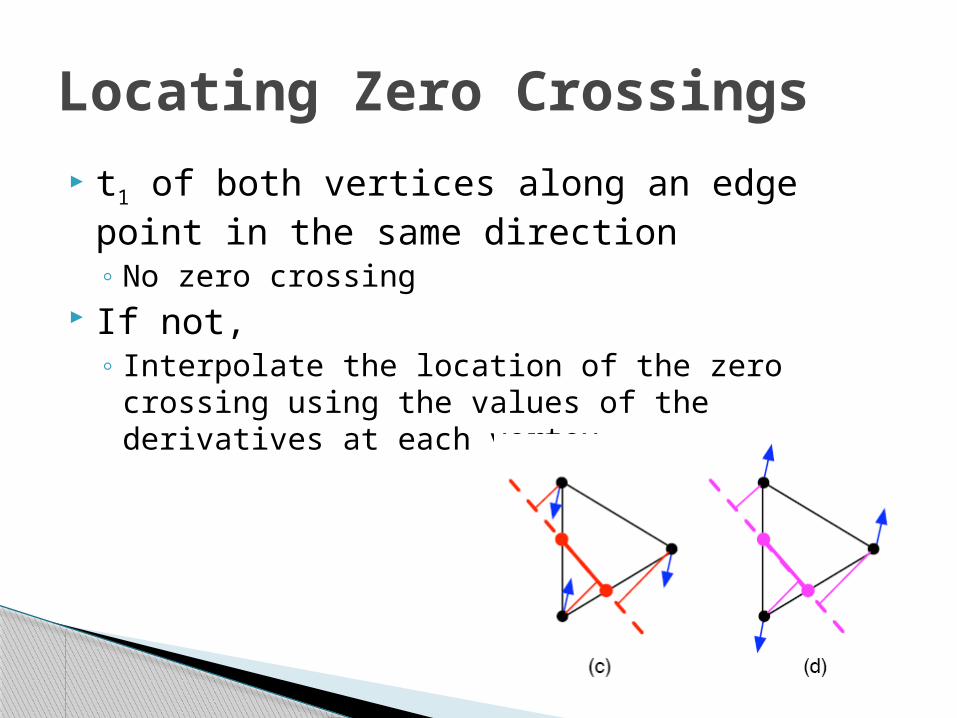
t1 of both vertices along an edge point in the same direction◦ No zero crossing
If not,◦ Interpolate the location of the zero crossing using
the values of the derivatives at each vertex
Locating Zero Crossings

We only want to draw lines at maxima
◦ Drop a perpendicular from each vertex to the zero crossing line
◦ If the positive t1 at each vertex makes an acute angle with the perpendicular, then the zero cross-ing is a maximum
Trimming

The result yields a lot of lines◦ we want points where the magnitude of the
view-dependent curvature is locally a maximum◦AND which this maximum has a high value
Eliminate lines based on a threshold of the view-dependent curvature◦ Scaled by the feature size of the mesh
(average edge length)
Thresholding

Performance Evaluation Ridges and valleys and suggestive contours are quick
to compute◦ Curvature is stable across viewpoints◦ Can be precomputed for an object
Unoptimized code on a 2.33 Ghz Intel Core 2 Duo Mac◦ Real time for small meshes◦ ~1.5 seconds for 50,000 polygon meshes◦ ~9 second for 250,000 polygon meshes
A limitation of apparent ridges is that they involve higher-order derivatives, which makes them prone to numerical noise in digital meshes

For fair comparison◦ used constant stroke width and sharp cutoffs for line
ends◦ Thresholded each image to match the number of gray
pixels per image
Contours are located where the normal is per-pendicular to the view direction◦ view-dependent curvature approaches a maximum of
infinity because of projection so contours are extracted as apparent ridges Some of other methods does not
must be combined with contours
Qualitative evaluation
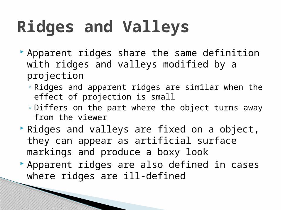
Apparent ridges share the same definition with ridges and valleys modified by a projection◦ Ridges and apparent ridges are similar when the ef-
fect of projection is small◦ Differs on the part where the object turns away from
the viewer Ridges and valleys are fixed on a object, they
can appear as artificial surface markings and produce a boxy look
Apparent ridges are also defined in cases where ridges are ill-defined
Ridges and Valleys
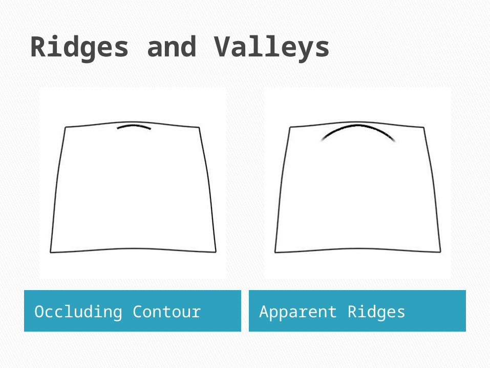
Ridges and Valleys
Occluding Contour Apparent Ridges

Suggestive contours look at an extremum of the normal◦ Apparent ridges look at the extremum of the normal
variation Look at curvature in the direction of the view
vector◦ While our approach look at curvature in the direction
of t1◦ These directions are defined differently, but some-
times they align Find where the curvature in the direction is 0
◦ While we find where the curvature is maximum
Suggestive Contours

It is hard to tell which method is clearly better◦ The methods are significantly different
Suggestive contours and apparent ridges trade off situations where they draw single or double lines
Suggestive Contours

Both suggestive contours and apparent ridges have an attribute of extending con-tour lines
Some important features in convex regions of an object are not conveyed by suggestive contours
Suggestive Contours

Given head-on illumination with a single light source at the viewpoint and lambertian shading
◦ Suggestive contours are drawn in the shaded ar-eas of an object Only make sense given a certain shading setup
◦ Apparent ridge lines are drawn where are im-portant independent of the light direction.
Suggestive Contours

Results

Results

Did a Monte-Carlo experiment where a diffuse surface is rendered from a given viewpoint with thousands of random lighting configurations◦ The average output of a Canny edge detector [Canny
1987] on those thousands of images matches re-markably well the lines extracted with our technique.
Comparison to edge detec-tion

Similar experiment with real photographs with flash illumination◦ Canny edge detection◦ Apparent ridges of 3D scan of the object◦ we can see that the two extraction approaches
agree
Comparison to edge detec-tion

Introduced apparent ridges for non-photorealistic line drawings
Produce visually pleasing line drawings◦ Capture important information about an object’s shape◦ independent of a specific lighting situation◦ Where ridges and valleys do well, apparent ridges ap-
pear in similar locations If ridges and valleys look boxy, apparent ridges modify
them to be more perceptually pertinent◦ Related to, but distinct from, suggestive contours
View dependent Both produce pleasing images, but in many cases appar-
ent ridge images are more appealing
Conclusion