SIEMENS DIGITAL INDUSTRIES SOFTWARE Formal Verification ...
21
SIEMENS DIGITAL INDUSTRIES SOFTWARE Formal Verification for DO-254 (and other Safety-Critical) Designs Executive summary DO-254 defines a process that hardware vendors must follow to get their hardware certified for use in avionics. All in-flight hardware (i.e., PLD, FPGA or ASIC designs) must comply with DO-254. This document focuses on the issue of advanced verification and tool assessment for DO-254, specifically for the Siemens EDA Questa Formal Verification tool. David Landoll and Mark Eslinger Siemens EDA siemens.com/eda
Transcript of SIEMENS DIGITAL INDUSTRIES SOFTWARE Formal Verification ...
SIEMENS DIGITAL INDUSTRIES SOFTWARE
Formal Verification for DO-254 (and other Safety-Critical) Designs
Executive summaryDO-254 defines a process that hardware vendors must follow to get their hardware certified for use in avionics. All in-flight hardware (i.e., PLD, FPGA or ASIC designs) must comply with DO-254. This document focuses on the issue of advanced verification and tool assessment for DO-254, specifically for the Siemens EDA Questa Formal Verification tool.
David Landoll and Mark Eslinger Siemens EDA
siemens.com/eda
Contents
Introduction 3
Overview of DO-254 3
DO-254 and Functional Verification 3
Why directed tests and simulation don’t
catch all bugs 4
The realities of verifying today’s FPGAs 6
Formal Verification – A better methodology for safety
critical designs 8
Formal verification demystified through examples 8
Examples of applying formal verification to safety critical
designs 11
Deploying formal to add safety to the verification process 13
The limitations of formal verification 13
Tool Assessment and DO-254 14
Independent Output Assessment 15
Relevant History 15
Basic Tool Qualification 15
“Qualifying” Siemens EDA Formal Verification for
DO-254 Designs 16
Conclusion 17
Appendix A: Glossary of Terms 17
SIEMENS DIGITAL INDUSTRIES SOFTWARE 2
White Paper – Formal Verification for DO-254 (and other Safety-Critical) Designs
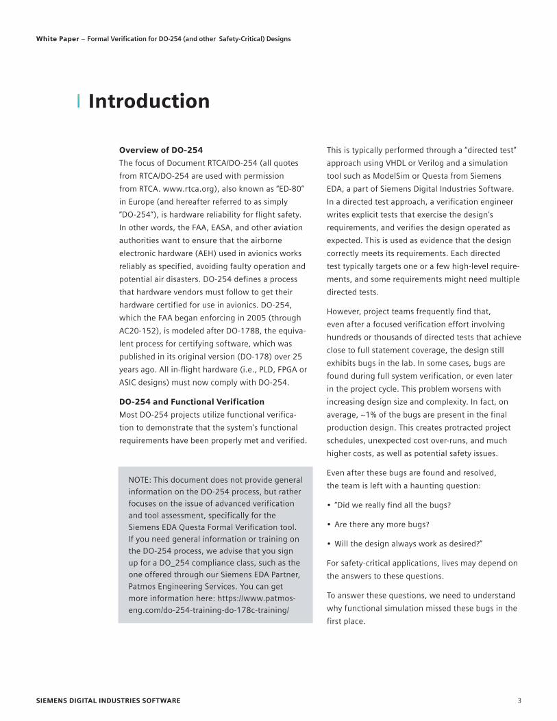
Overview of DO-254
The focus of Document RTCA/DO-254 (all quotes
from RTCA/DO-254 are used with permission
from RTCA. www.rtca.org), also known as “ED-80”
in Europe (and hereafter referred to as simply
“DO-254”), is hardware reliability for flight safety.
In other words, the FAA, EASA, and other aviation
authorities want to ensure that the airborne
electronic hardware (AEH) used in avionics works
reliably as specified, avoiding faulty operation and
potential air disasters. DO-254 defines a process
that hardware vendors must follow to get their
hardware certified for use in avionics. DO-254,
which the FAA began enforcing in 2005 (through
AC20-152), is modeled after DO-178B, the equiva-
lent process for certifying software, which was
published in its original version (DO-178) over 25
years ago. All in-flight hardware (i.e., PLD, FPGA or
ASIC designs) must now comply with DO-254.
DO-254 and Functional Verification
Most DO-254 projects utilize functional verifica-
tion to demonstrate that the system’s functional
requirements have been properly met and verified.
This is typically performed through a “directed test”
approach using VHDL or Verilog and a simulation
tool such as ModelSim or Questa from Siemens
EDA, a part of Siemens Digital Industries Software.
In a directed test approach, a verification engineer
writes explicit tests that exercise the design’s
requirements, and verifies the design operated as
expected. This is used as evidence that the design
correctly meets its requirements. Each directed
test typically targets one or a few high-level require-
ments, and some requirements might need multiple
directed tests.
However, project teams frequently find that,
even after a focused verification effort involving
hundreds or thousands of directed tests that achieve
close to full statement coverage, the design still
exhibits bugs in the lab. In some cases, bugs are
found during full system verification, or even later
in the project cycle. This problem worsens with
increasing design size and complexity. In fact, on
average, ~1% of the bugs are present in the final
production design. This creates protracted project
schedules, unexpected cost over-runs, and much
higher costs, as well as potential safety issues.
Even after these bugs are found and resolved,
the team is left with a haunting question:
• “Did we really find all the bugs?
• Are there any more bugs?
• Will the design always work as desired?”
For safety-critical applications, lives may depend on
the answers to these questions.
To answer these questions, we need to understand
why functional simulation missed these bugs in the
first place.
Introduction
NOTE: This document does not provide general
information on the DO-254 process, but rather
focuses on the issue of advanced verification
and tool assessment, specifically for the
Siemens EDA Questa Formal Verification tool.
If you need general information or training on
the DO-254 process, we advise that you sign
up for a DO_254 compliance class, such as the
one offered through our Siemens EDA Partner,
Patmos Engineering Services. You can get
more information here: https://www.patmos-
eng.com/do-254-training-do-178c-training/
SIEMENS DIGITAL INDUSTRIES SOFTWARE 3
White Paper – Formal Verification for DO-254 (and other Safety-Critical) Designs
Why directed tests and simulation don’t catch all bugs
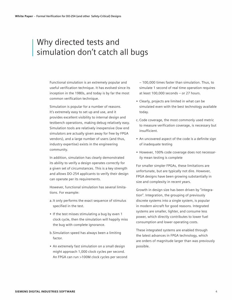
Functional simulation is an extremely popular and
useful verification technique. It has evolved since its
inception in the 1980s, and today is by far the most
common verification technique.
Simulation is popular for a number of reasons.
It’s extremely easy to set up and use, and it
provides excellent visibility to internal design and
testbench operations, making debug relatively easy.
Simulation tools are relatively inexpensive (low end
simulators are actually given away for free by FPGA
vendors), and a large number of users (and thus,
industry expertise) exists in the engineering
community.
In addition, simulation has clearly demonstrated
its ability to verify a design operates correctly for
a given set of circumstances. This is a key strength
and allows DO-254 applicants to verify their design
can operate per its requirements.
However, functional simulation has several limita-
tions. For example:
a. It only performs the exact sequence of stimulus
specified in the test.
• If the test misses stimulating a bug by even 1
clock cycle, then the simulation will happily miss
the bug with complete ignorance.
b. Simulation speed has always been a limiting
factor.
• An extremely fast simulation on a small design
might approach 1,000 clock cycles per second.
An FPGA can run >100M clock cycles per second
– 100,000 times faster than simulation. Thus, to
simulate 1 second of real time operation requires
at least 100,000 seconds – or 27 hours.
• Clearly, projects are limited in what can be
simulated even with the best technology available
today.
c. Code coverage, the most commonly used metric
to measure verification coverage, is necessary but
insufficient.
• An uncovered aspect of the code is a definite sign
of inadequate testing
• However, 100% code coverage does not necessar-
ily mean testing is complete
For smaller simpler FPGAs, these limitations are
unfortunate, but are typically not dire. However,
FPGA designs have been growing substantially in
size and complexity in recent years.
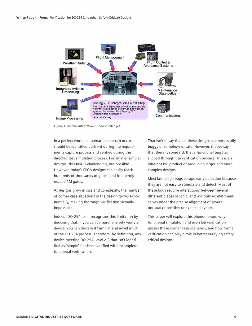
Growth in design size has been driven by “integra-
tion”. Integration, the grouping of previously
discrete systems into a single system, is popular
in modern aircraft for good reasons. Integrated
systems are smaller, lighter, and consume less
power, which directly contributes to lower fuel
consumption and lower operating costs.
These integrated systems are enabled through
the latest advances in FPGA technology, which
are orders of magnitude larger than was previously
possible.
SIEMENS DIGITAL INDUSTRIES SOFTWARE 4
White Paper – Formal Verification for DO-254 (and other Safety-Critical) Designs
In a perfect world, all scenarios that can occur
should be identified up-front during the require-
ments capture process and verified during the
directed test simulation process. For smaller simpler
designs, this task is challenging, but possible.
However, today’s FPGA designs can easily reach
hundreds-of-thousands of gates, and frequently
exceed 1M gates.
As designs grow in size and complexity, the number
of corner case situations in the design grows expo-
nentially, making thorough verification virtually
impossible.
Indeed, DO-254 itself recognizes this limitation by
declaring that, if you can comprehensively verify a
device, you can declare it “simple” and avoid much
of the DO-254 process. Therefore, by definition, any
device meeting DO-254 Level A/B that isn’t identi-
fied as “simple” has been verified with incomplete
functional verification.
That isn’t to say that all these designs are necessarily
buggy or somehow unsafe. However, it does say
that there is some risk that a functional bug has
slipped through the verification process. This is an
inherent by- product of producing larger and more
complex designs.
Most late-stage bugs escape early detection because
they are not easy to stimulate and detect. Most of
these bugs require interactions between several
different pieces of logic, and will only exhibit them-
selves under the precise alignment of several
unusual or possibly unexpected events.
This paper will explore this phenomenon, why
functional simulation and even lab verification
misses these corner case scenarios, and how formal
verification can play a role in better verifying safety
critical designs.
Figure 1: Avionic integration — new challenges.
SIEMENS DIGITAL INDUSTRIES SOFTWARE 5
White Paper – Formal Verification for DO-254 (and other Safety-Critical) Designs
Let’s examine a small design to better understand
this functional verification challenge.
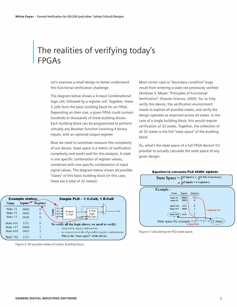
The diagram below shows a 4-input Combinational
logic cell, followed by a register cell. Together, these
2 cells form the basic building block for an FPGA.
Depending on their size, a given FPGA could contain
hundreds or thousands of these building blocks.
Each building block can be programmed to perform
virtually any Boolean function involving 4 binary
inputs, with an optional output register.
Now we need to somehow measure the complexity
of our device. State space is a metric of verification
complexity and works well for this analysis. A state
is one specific combination of register values,
combined with one specific combination of input
signal values. The diagram below shows all possible
“states” of this basic building block (in this case,
there are a total of 32 states):
Most corner case or “boundary condition” bugs
result from entering a state not previously verified
(Andreas S. Meyer, “Principles of Functional
Verification”, Elsevier Science, 2004). So, to fully
verify this device, the verification environment
needs to explore all possible states, and verify the
design operates as expected across all states. In the
case of a single building block, this would require
verification of 32 states. Together, the collection of
all 32 states is the full “state space” of the building
block.
So, what’s the state space of a full FPGA device? It’s
possible to actually calculate the state space of any
given design:
The realities of verifying today’s FPGAs
Figure 2: All possible states of a basic building block.
Figure 3: Calculating the PLD state space.
SIEMENS DIGITAL INDUSTRIES SOFTWARE 6
White Paper – Formal Verification for DO-254 (and other Safety-Critical) Designs
We can use this formula to calculate the state space
for a design loaded in an FPGA device. To demon-
strate the concept, lets target an example FPGA that
has a mere 1000 gates and assume the design is
occupying one third of the available logic.
Category Max Actual
Max Clock Speed 75 MHz 75 MHz
Equivalent ASIC Gates 1K
Logic Modules 292 97
Flip Flops (Registers) 147 49
Available User I/O 57 10
State space calculation: (Conservative Estimate)
State space = 2(49 Registers + 10 Inputs) = 259
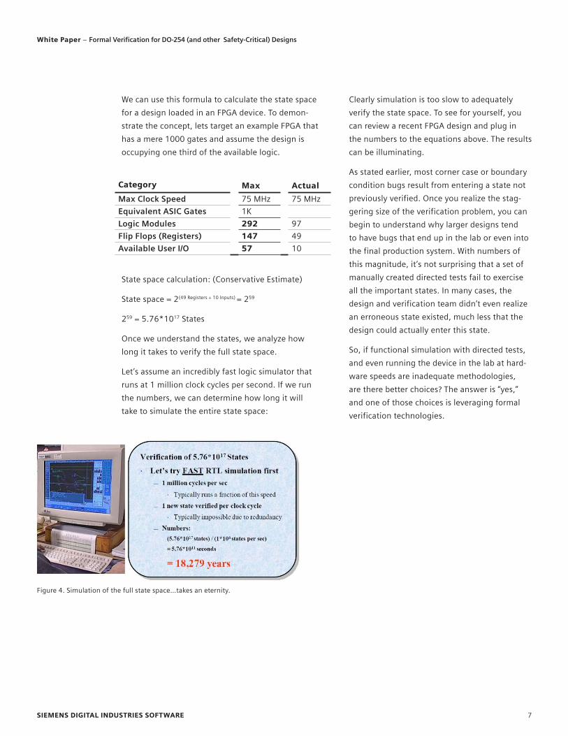
259 = 5.76*1017 States
Once we understand the states, we analyze how
long it takes to verify the full state space.
Let’s assume an incredibly fast logic simulator that
runs at 1 million clock cycles per second. If we run
the numbers, we can determine how long it will
take to simulate the entire state space:
Figure 4. Simulation of the full state space…takes an eternity.
Clearly simulation is too slow to adequately
verify the state space. To see for yourself, you
can review a recent FPGA design and plug in
the numbers to the equations above. The results
can be illuminating.
As stated earlier, most corner case or boundary
condition bugs result from entering a state not
previously verified. Once you realize the stag-
gering size of the verification problem, you can
begin to understand why larger designs tend
to have bugs that end up in the lab or even into
the final production system. With numbers of
this magnitude, it’s not surprising that a set of
manually created directed tests fail to exercise
all the important states. In many cases, the
design and verification team didn’t even realize
an erroneous state existed, much less that the
design could actually enter this state.
So, if functional simulation with directed tests,
and even running the device in the lab at hard-
ware speeds are inadequate methodologies,
are there better choices? The answer is “yes,”
and one of those choices is leveraging formal
verification technologies.
SIEMENS DIGITAL INDUSTRIES SOFTWARE 7
White Paper – Formal Verification for DO-254 (and other Safety-Critical) Designs
Imagine a perfect solution to the functional verification problem. Imagine a tech-
nology than could analyze the entire state space, including all possible combinations
and permutations of all design inputs, combined with all possible combinations of all
possible internal design states, across all time, and determine once and for all: Is the
design functionally correct?
This technology does exist. It is called formal verification…and it works.
First, the term formal verification in general involves using mathematics as an
analysis method. Formal verification can take one of several forms. For example,
equivalence checking is a form of formal verification that compares two models to
determine if they are functionally the same. This paper does not refer to equivalence
checking. In this article, we are referring to a form of formal verification called model
checking. Model checking performs a mathematical analysis that a specific design
behavior will always, under all circumstances, behave correctly.
Now, this said, formal verification is an amazing technology, but it does have limita-
tions. These will be explored later in this paper. First, let’s discuss what formal verifi-
cation is, how it works, and how you could apply it to a DO-254, safety critical design.
Formal verification demystified through examples
A formal verification tool is quite different than a functional simulator. When people
are confused by formal verification, the typical cause is an attempt to relate formal
methods to simulation-based methods and code coverage. Comparing formal to
simulation is a fool’s errand because the underlying technologies are fundamentally
and profoundly different. However, because simulation is the most commonly under-
stood verification technology, here’s a simple example as an analogy to try to bridge
the gap.
Imagine trying to solve the following math problem:
3B3 = 65,856
Formal Verification – A better methodology for safety critical designs
SIEMENS DIGITAL INDUSTRIES SOFTWARE 8
White Paper – Formal Verification for DO-254 (and other Safety-Critical) Designs
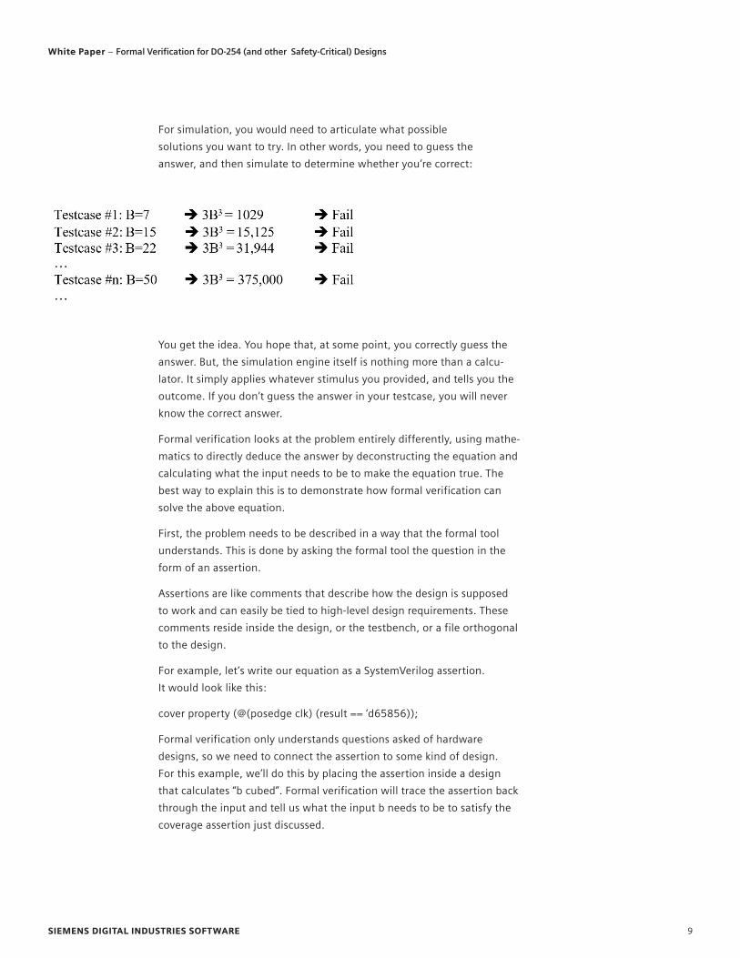
For simulation, you would need to articulate what possible
solutions you want to try. In other words, you need to guess the
answer, and then simulate to determine whether you’re correct:
You get the idea. You hope that, at some point, you correctly guess the
answer. But, the simulation engine itself is nothing more than a calcu-
lator. It simply applies whatever stimulus you provided, and tells you the
outcome. If you don’t guess the answer in your testcase, you will never
know the correct answer.
Formal verification looks at the problem entirely differently, using mathe-
matics to directly deduce the answer by deconstructing the equation and
calculating what the input needs to be to make the equation true. The
best way to explain this is to demonstrate how formal verification can
solve the above equation.
First, the problem needs to be described in a way that the formal tool
understands. This is done by asking the formal tool the question in the
form of an assertion.
Assertions are like comments that describe how the design is supposed
to work and can easily be tied to high-level design requirements. These
comments reside inside the design, or the testbench, or a file orthogonal
to the design.
For example, let’s write our equation as a SystemVerilog assertion.
It would look like this:
cover property (@(posedge clk) (result == ‘d65856));
Formal verification only understands questions asked of hardware
designs, so we need to connect the assertion to some kind of design.
For this example, we’ll do this by placing the assertion inside a design
that calculates “b cubed”. Formal verification will trace the assertion back
through the input and tell us what the input b needs to be to satisfy the
coverage assertion just discussed.
SIEMENS DIGITAL INDUSTRIES SOFTWARE 9
White Paper – Formal Verification for DO-254 (and other Safety-Critical) Designs
Let’s write the design in SystemVerilog (although
we could also choose VHDL or Verilog), and include
the assertion at the bottom of the design:
module three_b_cubed_module (
input clk, rstn,
input [7:0] b,
output reg [19:0] result
);
always@(posedge clk or negedge rstn)
if (!rstn)
result <= ‘0;
else
result <= ‘d3*(b*b*b); //result = 3b^3
//The next statement is our “coverage assertion”
//Formal will show us the input stimulus needed
//to solve our equation
cover property (@(posedge clk) result == ‘d65856
);
endmodule
That’s it. Now, when we give this Verilog module
to the Siemens EDA Questa Formal Verification
tool, it will come back in seconds with the
answer: 28. No guessing involved. How did it do
it? Just like you learned in school:3B3 = 65856
B3 = (65856)/3 = 21952 B = 219521/3 = 28
Done.
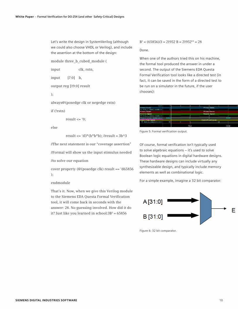
When one of the authors tried this on his machine,
the formal tool produced the answer in under a
second. The output of the Siemens EDA Questa
Formal Verification tool looks like a directed test (in
fact, it can be saved in the form of a directed test to
be run on a simulator in the future, if the user
chooses):
Figure 5: Formal verification output.
Figure 6: 32 bit comparator.
Of course, formal verification isn’t typically used
to solve algebraic equations – it’s used to solve
Boolean logic equations in digital hardware designs.
These hardware designs can include virtually any
synthesizable design, and typically include memory
elements as well as combinational logic.
For a simple example, imagine a 32 bit comparator:
SIEMENS DIGITAL INDUSTRIES SOFTWARE 10
White Paper – Formal Verification for DO-254 (and other Safety-Critical) Designs

If this functionality came from a requirement,
it would look like this:
The comparator output shall be active when
and only when the input A equals input B;
Imagine you’ve created your comparator. Will your
implementation of the 32 bit comparator always
produce the correct answer? This comparator has
264 possible input combinations. Imagine trying to
write simulation testcases to try all input combina-
tions. Your testcases need to cover
18,400,000,000,000,000,000 different input
combinations. Even in hardware in the lab running
at 1 GHz (very fast logic, indeed), this design would
require 584 years to try every single input
combination.
Formal verification can analyze all possible inputs
and answer this question in a fraction of a second.
You simply give formal your design (i.e., a synthesiz-
able design written in a common HDL language
such as VHDL, Verilog, or SystemVerilog) and the
assertion (typically written in SystemVerilog) as
follows (PSL shown):
assert always (A==B) <-> E;
That is, whenever A equals B, it implies E is true. The
reverse is also true. If E is true, it implies A equals B.
That’s what the “<->” means. Each side implies the
other is true.
To obtain this answer, formal verification examines
the assertion, traces back through the design to the
inputs, and then mathematically identifies all failure
conditions (if any exist). If there are any failure
combinations (i.e., conditions when the comparator
fails to operate as per the assertion), they will be
reported to the user. If no failure conditions exist,
then the design is proven to always behave properly
with respect to this requirement, and you have
complete confidence that the design is correct.
It is beyond the scope of this paper to describe the
exact mathematical Boolean logic equations and
methods a formal tool uses to perform this analysis.
However, the reasoning is quite similar to the earlier
mathematical solution to 3B3 = 65,856 shown
earlier.
Examples of applying formal verification
to safety critical designs
Formal verification becomes more interesting when
applied to a real avionics safety critical application.
Imagine you are designing a “reverse thruster
control FPGA.” Your FPGA controls the deployment
of the reverse thrusters on a Boeing 737.
If you’re not familiar with reverse thrusters on a
737, they’re used when the plane is coming in for a
landing. Metal plates close around the rear of the
engines. This causes the thrust from the engine to
hit the plates, and flow back over the wing toward
the front of the aircraft. This makes the thrust push
forward and quickly slows down the airplane.
This works well when the plane is on the ground
and needs to quickly slow down. However, if the
reverse thrusters deploy mid-flight, the airplane will
quite likely crash. So, if you were designing the
FPGA controlling these reverse thrusters, you would
want to make very sure they only deploy when they
should.
Figure 7: Reverse
thruster misfire.
SIEMENS DIGITAL INDUSTRIES SOFTWARE 11
White Paper – Formal Verification for DO-254 (and other Safety-Critical) Designs

Your requirement might look something like this:
Requirement Name Description
REQ_REV_THRUST_002
Reverse thrusters shall only deploy when Weight On Wheels has been positively detected.
To verify this in formal verification, we need to repre-
sent this requirement as an assertion:
property REQ_REV_THRUST_002;
@(posedge clk)
always fire_reverse_thrusters |->
Weight_on_wheels_notification;
endproperty;
a_REQ_REV_THRUST_002: assert property
(REQ_REV_THRUST_002);
Here is a description of this assertion in English:
The assertion is named “REQ_REV_THRUST_002”,
matching the requirement name.
If the output “fire_reverse_thrusters” is active, it always
implies that the input “Weignt_on_wheels_notification”
is already active. If this is NOT the case, “fire the asser-
tion”, and show me how it can happen!
If you were to run your design and this assertion in
formal verification, you would receive either a wave-
form demonstrating a sequence of inputs that causes
fire_reverse_thrusters without Weight_on_wheels, or
you would receive a formal proof that it can never
happen, meaning your design is always functionally
correct with respect to your requirements.
For example, a formal verification run may come
back with an assertion violation indicating that
fire_reverse_thrusters can activate without Weight_
on_wheels if test_mode is activated. However, let’s
assume this is expected, and that test_mode will be
tied to 1’b0 (ground) on the board. So, this firing
can be excluded. The engineer can document this
analysis and create a formal verification constraint
saying “test_mode == 1’b0”. Now, with test_mode
inactive, the engineer can rerun formal verification,
and it can respond with a formal proof of correct-
ness, indicating the design is truly 100% error free
across the entire state space with respect to the
requirement(s) provided.
If you were to run your design and this assertion in
formal verification, you would receive either a
waveform demonstrating a sequence of inputs that
causes fire_reverse_thrusters without Weight_on_
wheels, or you would receive a formal proof that it
can never happen, meaning your design is always
functionally correct with respect to your
requirements.
For example, a formal verification run may come
back with an assertion violation indicating that
fire_reverse_thrusters can activate without Weight_
on_wheels if test_mode is activated. However, let’s
assume this is expected, and that test_mode will be
tied to 1’b0 (ground) on the board. So, this firing
can be excluded. The engineer can document this
analysis and create a formal verification constraint
saying “test_mode == 1’b0”. Now, with test_mode
inactive, the engineer can rerun formal verification,
and it can respond with a formal proof of correct-
ness, indicating the design is truly 100% error free
across the entire state space with respect to the
requirement(s) provided.
Clearly, formal verification is valuable for safety
critical applications and is far superior than guessing
how the design might fail using functional simula-
tion or lab verification.
SIEMENS DIGITAL INDUSTRIES SOFTWARE 12
White Paper – Formal Verification for DO-254 (and other Safety-Critical) Designs
Deploying formal to add safety to the verification
process
However incomplete, functional simulation does
play a critical role in FPGA verification. Functional
simulation efficiently demonstrates a device can
operate correctly with respect to its requirements.
However, where functional simulation breaks down
is trying to demonstrate that the device will always
operate as it should under all circumstances. In
other words, functional simulation does a poor job
exploring the states around a functional require-
ment. This is where the remaining bugs can typically
be found.
Therefore, the best results will be achieved when
simulation and formal model checking are used
together in a complementary way. There is a great
deal of collateral available from Siemens EDA on this
subject. In general, the idea is to verify using tradi-
tional simulation techniques, then augment using
formal analysis to better assure all remaining corner
cases have been analyzed.
In addition, the best formal results are achieved
when used on designs that are the most difficult for
simulation-based verification. Empirically, my expe-
rience using and deploying formal verification has
found that these are designs with complex control
logic and/or concurrency within the design. This
could include designs with arbitration logic, stan-
dard bus interface logic, state machines, interrupt
logic, etc.
As with most verification tools and methodologies,
formal model checking can be used to successfully
verify many different types of designs, but not all.
The limitations of formal verification
There are some types of designs that are excellent
for formal and are extremely challenging to verify
using other techniques. For example, arbiters are
traditionally quite difficult to verify using simula-
tion-based techniques but are typically very easy to
verify with formal.
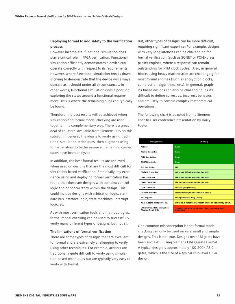
But, other types of designs can be more difficult,
requiring significant expertise. For example, designs
with very long latencies can be challenging for
formal verification (such as SONET or PCI-Express
packet engines, where a response can remain
outstanding for >1M clock cycles). Also, in general,
blocks using heavy mathematics are challenging for
most formal engines (such as encryption blocks,
compression algorithms, etc.). In general, graph-
ics-based designs can also be challenging, as it’s
difficult to define correct vs. incorrect behavior,
and are likely to contain complex mathematical
operations.
The following chart is adapted from a Siemens
User-to-User conference presentation by Harry
Foster.
One common misconception is that formal model
checking can only be used on very small and simple
designs. This is not true. Designs over 1M gates have
been successful using Siemens EDA Questa Formal.
A typical design is approximately 100-200K ASIC
gates, which is the size of a typical chip-level FPGA
design.
SIEMENS DIGITAL INDUSTRIES SOFTWARE 13
White Paper – Formal Verification for DO-254 (and other Safety-Critical) Designs
However, even with these limitations stated, there
are a large number of designs that are readily verifi-
able using formal techniques. These tend to contain
complex control logic and standard bus interfaces,
which aligns well with many safety critical designs.
One key aspect of the DO-254 process is to deter-
mine that the tools used to create and verify designs
are working properly. The process to ensure this is
called “tool assessment” (though it is often mistak-
enly called “tool qualification”). Tool qualification is
one method of tool assessment.
The purpose of tool assessment (and potentially tool
qualification) is to ensure that tools that automate,
minimize, or replace manual processes for hardware
design and/or verification perform to an acceptable
level of confidence on the target project. Tools are
classified as either design tools or verification tools,
depending on which design flow processes they
automate. Likewise, as mentioned previously,
designs are designated with a criticality level (A-E)
that corresponds to the resulting severity of failure.
The rigor of the tool assessment process depends on
both the tool classification as well as the criticality
level of the designated project.
Section 11, “Additional Considerations” of the
DO-254 specification discusses “Tool Assessment.”
Figure 3 shows the flow diagram presented in this
section of the specification.
To get started, simply start applying formal verifica-
tion to all arbiters. This alone can improve safety for
many types of designs.
The tool assessment and qualification process takes
one of three forms:
• Independent Output Assessment (see item 3 in
figure 3) This means that another independent
tool or method must validate the results of the
tool.
• Relevant History (see item 5 in figure 3)This
means the tool has been previously used and
has been shown to provide acceptable results.
• Tool Qualification (see item 7 in figure 3)This
requires establishing and executing a plan to
confirm that the tool produces correct outputs
for its intended application.
Regardless of these classifications, the task of
tool assessment falls upon the airborne applicant
or airborne integrator (not the tool vendor). The
applicant or integrator proposes the method of
tool assessment as part of the DO-254 planning
and documentation. The certification agency or its
representative (in North America, this would be a
Designated Engineering Representative, or DER) will
determine if the proposed method of compliance to
this requirement is adequate for the development
process.
Tool Assessment and DO-254
SIEMENS DIGITAL INDUSTRIES SOFTWARE 14
White Paper – Formal Verification for DO-254 (and other Safety-Critical) Designs

Figure 8: “Design and Verification Tool Assessment and Qualification” Flow
Diagram
“Independent assessment of a verification tool’s output may include a manual review of the tool outputs or may include a comparison against the outputs of a separate tool capable of performing the same verification activity as the tool being assessed. The applicant may propose other methods of independent assessment as well.”
Relevant HistoryDO-254 describes relevant history as follows:
“When it is possible to show that the tool has been previously used and has been found to produce acceptable results, then no further assessment is necessary. A discussion of the relevance of the previous tool usage versus the proposed usage of the tool should be included in the justification. Note: The history of the tool may be based on either an airborne or non-air-borne application, provided that data is avail-able to substantiate the relevance and credibility of the tool’s history.”
Basic Tool QualificationDO-254 describes tool qualification as follows:
“…if no such relevant history can be evidenced, then the tool must undergo “Basic Tool Qualification” which includes tool configura-tion control, a tool problem reporting process, and a process “to confirm that the tool produces correct outputs for its intended application using analysis or testing.”
The following sub-sections provide the DO-254
description of the key methods for tool assessment/
qualification. Clarification on how this applies to
Siemens EDA functional verification begins in the
next section.
Independent Output AssessmentDO-254 section 11.4.1 describes independent
output assessment as follows:
“An independent assessment verifies the correct-ness of the tool output using an independent means. If the tool output is independently assessed, then no further assessment is necessary.”
SIEMENS DIGITAL INDUSTRIES SOFTWARE 15
White Paper – Formal Verification for DO-254 (and other Safety-Critical) Designs
“Qualifying” Siemens EDA Formal Verification for DO-254 Designs
The tool discussed in this example is the Siemens EDA formal verification tool suite
called Questa Formal Verification. Questa Formal Verification is a suite of model
checking apps used by companies worldwide, including those producing flight
hardware.
While a tool vendor cannot assess or qualify their own tools and the FAA does not
provide blanket approval for use of any tools in DO-254 projects, what follows are
explanations and suggestions for getting through the assessment process for Questa
Formal Verification, as easily as possible.
The first thing to ask when considering using Questa Formal Verification on a
DO-254 project is “Do I Even Need to Mention It?” In other words, not all tools have to
be identified and described in the “Plan for Hardware Aspects of Certification” (PHAC)
or other DO-254 documents. You only have to do this if you want to claim credit for
their use, and you only need to claim credit for use of a tool if there is some project
requirement that must be fulfilled by using this tool.
Without a doubt, Siemens EDA functional verification provides added assurance that
the design will function correctly within the intended system (remember, this is the
intent of DO-254). However, unless you have a specific requirement identified by
your end customer that says you must supplement your simulation-based testing
with formal methods, you can just run Questa Formal Verification on your project
without it becoming part of the DO-254 review process.
On the other hand, ideally, your end customer or certification authority should
recognize the importance of thorough verification and applaud your effort to go
beyond the traditional to ensure the design will perform as intended – especially
the safety-critical functions. In this case, you would likely be seeking some credit for
using formal methods as “Advanced Methods” for your level A/B design (as specified
in DO-254 Appendix B). Unfortunately, this would likely mean that you need to go
through the assessment process.
A suggested method to do this involves using simulation as an independent output
assessment method. The full explanation of this methodology is beyond the scope of
this paper but is available upon request.
SIEMENS DIGITAL INDUSTRIES SOFTWARE 16
White Paper – Formal Verification for DO-254 (and other Safety-Critical) Designs
Conclusion
Today’s FPGAs, and subsequently FPGA designs, are
growing very rapidly. Large safety critical designs
are reaching 1M ASIC gates and beyond. These
safety critical designs are typically verified using
only simulation based directed test verification.
However, it’s clear that simulation-based verification
methods must be complemented to adequately
verify the near infinite state space of these large
designs. Without better verification, it’s impossible
to clearly demonstrate that a safety critical design
is truly robust.
Appendix A: Glossary of Terms
What follows are terms you may encounter as you
embark upon DO-254/DO-178B projects. NOTE: A
full listing of FAA acronyms can be found here:
http://www.gps.tc.faa.gov/glossary.html
• AC – Advisory Circular, such as AC-152 which
enforces DO-254 for “custom microcoded devices”
• ACO – Aircraft Certification Office, a local office
of the FAA that assists with design approval and
certificate management; US production approvals;
engineering and analysis questions; investigating
and reporting aircraft accidents, incidents, and
service difficulties; DER oversight.
• AIR – AIRcraft certification service. There are
various divisions of the FAA, such as AIR 120 and
AIR 200, which are all involved in various aspects
of aircraft certification.
• AMOC – Acceptable Means of Compliance, for
example, code coverage is an AMOC for verifica-
tion metrics
• AOPA – Aircraft Operators and Pilots Association
• ARINC – Aeronautical Radio Incorporated, a
company that is the leading provider of transpor-
tation communications and systems engineering
solutions for five major industries: aviation,
airports, defense, government, and transporta-
tion, also synonymous with various ARINC parts
such as the ARINC 429, a two-wire data bus that is
application-specific for commercial and transport
aircraft.
• ARP – Aerospace Recommended Practice, for
example ARP 5754 “Guidance for Development
Validation and Verification of Complex Aircraft
Systems”
• CAST – Certification Authorities Software Team,
an international group of participants from What
follows are terms you may encounter as you
embark upon DO-254/DO-178B projects. NOTE:
A full listing of FAA acronyms can be found here:
http://www.gps.tc.faa.gov/glossary.html
Siemens EDA Questa Formal Verification, the market
leader in formal model checking, can work with
simulation to greatly improve design safety and
reliability. In addition, this can provide additional
DO-254 credit under the heading of “robustness”.
SIEMENS DIGITAL INDUSTRIES SOFTWARE 17
White Paper – Formal Verification for DO-254 (and other Safety-Critical) Designs
• AC – Advisory Circular, such as AC-152 which
enforces DO-254 for “custom microcoded devices”
• ACO – Aircraft Certification Office, a local office
of the FAA that assists with design approval and
certificate management; US production approvals;
engineering and analysis questions; investigating
and reporting aircraft accidents, incidents, and
service difficulties; DER oversight.
• AIR – AIRcraft certification service. There are
various divisions of the FAA, such as AIR 120 and
AIR 200, which are all involved in various aspects
of aircraft certification.
• AMOC – Acceptable Means of Compliance, for
example, code coverage is an AMOC for verifica-
tion metrics
• AOPA – Aircraft Operators and Pilots Association
• ARINC – Aeronautical Radio Incorporated, a
company that is the leading provider of transpor-
tation communications and systems engineering
solutions for five major industries: aviation,
airports, defense, government, and transporta-
tion, also synonymous with various ARINC parts
such as the ARINC 429, a two-wire data bus that is
application-specific for commercial and transport
aircraft.
• ARP – Aerospace Recommended Practice, for
example ARP 5754 “Guidance for Development
Validation and Verification of Complex Aircraft
Systems”
• CAST – Certification Authorities Software Team,
an international group of participants from world-
wide aviation certification authorities including
the FAA, despite the name this group discusses
complex electronic hardware issues also
• CEH – Complex Electronic Hardware, for the
context of DO-254, this means custom microcoded
devices (PLD, FPGA, ASIC)
• CFAR -- Code of Federal Aviation Regulations
• CFR – Code of Federal Regulations, such as CFR §
183.29, which defines criteria for DERs
• CRI – Certification Review Item, as per EASA.
Pronounced “Kree,” these are requirements above
and beyond DO-254/ED-80, such as the CRIs for
the Airbus 380 or A400M projects.
• DAL – Design Assurance Level, a safety criticality
rating from level A-E, with level A/B being the
most critical and requiring the most stringent
DO-254/DO-178B process.
○ Level A: Where a software/hardware failure
would cause and or contribute to a cata-
strophic failure of the aircraft flight control
systems.
○ Level B: Where a software/hardware failure
would cause and or contribute to a hazard-
ous/severe failure condition in the flight
control systems.
○ Level C: Where a software/hardware failure
would cause and or contribute to a major
failure condition in the flight control
systems.
○ Level D: Where a software/hardware failure
would cause and or contribute to a minor
failure condition in the flight controls
systems.
SIEMENS DIGITAL INDUSTRIES SOFTWARE 18
White Paper – Formal Verification for DO-254 (and other Safety-Critical) Designs
○ Level E: Where a software/hardware failure
would have no adverse effect on the aircraft
or on pilot workload.
• DER – Designated Engineering Representative, an
individual, appointed by the FAA to approve or
recommend approval of technical data to the FAA.
These individuals can work for a specific company
(such as Boeing) or be independent consultants
and serve as DERs to many other companies.
• DO – Document, from RTCA
• DO-178B -- Software Considerations in Airborne
Systems and Equipment Certification, an aviation
industry standard since 1992. A DO-178C stan-
dard is being worked on for release in 2009(?)
• DO-254 – Design Assurance Guidance for Airborne
Electronic Hardware, put into effect on FPGA/ASIC
designs via AC 20-152 in 2005
• DO-297 – Integrated Modular Avionics (IMA)
Development Guidance and Certification
Considerations
• EASA – European Aviation Safety Agency, EU
counterpart of FAA, pronounced “ee ah sa”
• ED-12 – EU equivalent of DO-178B
• ED-80 – EU equivalent of RTCA/DO-254
• EUROCAE – European Organization for Civil
Aviation Equipment, equivalent of RTCA in the US,
pronounced “Euro Kay”
• FAA – Federal Aviation Administration, the US
authority governing aviation
• FAR - Federal Aviation Regulation, a set of require-
ments (US) that determines airworthiness of an
aircraft. For example, large aircraft are subject to
FAR 25 certification. See also JAR.
• HDP -- Hardware Development Plan, one of the 5
plans required for DO-254
• HVP – Hardware Verification Plan, one of the 5
plans required for DO-254
• IMA, IMS – Integrated modular avionics, inte-
grated modular systems, DO-297 deals with this
level of design
• IP – besides the traditional meaning (i.e., “intel-
lectual property”), can also mean Issue Paper, a
paper supplementing an FAA standard to clarify a
problem, solution or issue not well defined within
a standard.
• JAR – Joint Airworthiness Requirements is a set of
requirements (EU) that determine airworthiness
of an aircraft. For example, large aircraft are
subject to JAR 25 certification. See also FAR.
• JPDO – Joint Planning and Development Office,
established to facilitate NextGen (Next Generation
Air Transportation System, refers to a wide-rang-
ing initiative to transform the air traffic control
system) activities. JPDO is working with the
FAA, NASA, the Departments of Transportation,
Defense, Homeland Security, Commerce, and the
White House Office of Science and Technology
Policy.
• LOFI – Level of FAA involvement example LOFI on
CEH projects. This is a defined evaluation criteria
for establishing how much FAA involvement there
should be for a given software program (See
Order 8110.49). There is currently no LOFI deter-
mination for CEH/DO-254, this may be part of the
draft Order 8110.CEH currently being working on.
• MASPS - Minimum Aviation System Performance
Specifications, for example an FAA MASPS
specifies that weather information for the local
region (50 miles radius or more) is continuously
transmitted at least every five minutes
• NASA – National Aeronautics & Space
Administration
• NextGen – NEXT GENeration air transportation
system, a project to integration aircraft, airports
and air traffic control to accommodate much
higher volumes of air travelers/traffic in the
future.
SIEMENS DIGITAL INDUSTRIES SOFTWARE 19
White Paper – Formal Verification for DO-254 (and other Safety-Critical) Designs
• Order – An Order is a way for the FAA to address
regulatory concerns in a quick but global way.
Regulatory changes to the CFARs (code of Federal
Aviation Regulations) take a long time and have to
go through lots of steps. An Order has a specific
impact to a smaller audience and is used for
changes to a technology area or specific topic.
Example Order 8110.CEH.
• PHAC – Plan for Hardware Aspects of Certification,
the main plan document required by DO-254.
The other plans include Quality Assurance Plan,
Configuration Management Plan, Hardware
Development Plan, Hardware Verification Plan and
Hardware Standards.
• PSAC -- Plan for Software Aspects of Certification,
the main plan document required by DO-178B.
• RMA - Rate Monotonic Analysis is a simple,
practical, mathematically sound way to guarantee
schedule-ability in real-time systems
• RTCA – Radio Technical Committee on
Aeronautics, a private, not-for-profit corporation
that develops consensus-based recommendations
regarding communications, navigation, surveil-
lance, and air traffic management (CNS/ATM)
system issues. RTCA functions as a Federal Advisor
Committee. Its recommendations are used by the
Federal Aviation Administration (FAA) as the basis
for policy, program, and regulatory decisions and
by the private sector as the basis for development,
investment and other business decisions.
• SAE – Society of Automotive engineers, some
subset of this group specializes in aeronautics
• SARP – Standards and Recommended Practices
• SC – Special Committee, anything that starts with
SC is an industry working committee to discuss
and resolve particular issues. Examples include
SC-180 CEH (wrote the DO-254 standard), SC-200
integrated modular avionics, SC-205 software for
aeronautical use. See also WG.
• SOI 1-4 – Stage of Involvement, one of 4 required
review points between a airborne applicant/
integrator and certification authority during the
DO-178B or DO-254 process.
• Space Partitioning – Using the hardware MMU to
enforce software partitioning of data and instruc-
tion regions in memory.
• STC or Supplemental Type Certificate – Granted by
the FAA for new equipment in a specific aircraft.
See also TC.
• Time Partitioning – using an operating system’s
scheduler to ensure that selected tasks and
processes have access to the CPU for a specified
amount of time within a specific period
• TC or Type Certificate – Granted by the FAA to
certify an entire aircraft. See also STC.
• TSO or Technical Standard Order – Governs the
minimum performance standard for materials,
parts and appliances on civil aircraft.
• UAS – Unmanned Aircraft Standards, DO-304,
guidance just produced by SC-203 and being
considered by FAA. Requires both DO-254 and
DO-178B certification.
• V&V – Validation and Verification
• WG – Working Group from EuroCAE, the EU equiv-
alent of the US-based SC (special committees,
oftentimes linked directly to these activities,
examples wG-72 is leading the effort on aeronau-
tical systems security, WG-71 = SC-205
• STC – Supplemental Type Certificate, a document
issued by the Federal Aviation Administration
approving a product (aircraft, engine, or propel-
ler) modification.
• TC – Type Certification
• TSO – Technical Standard Order, a minimum
performance standard issued by the FAA for spec-
ified materials, parts, processes, and appliances
used on civil aircraft
SIEMENS DIGITAL INDUSTRIES SOFTWARE 20
White Paper – Formal Verification for DO-254 (and other Safety-Critical) Designs
About Siemens Digital Industries Software
Siemens Digital Industries Software is driving transformation to
enable a digital enterprise where engineering, manufacturing
and electronics design meet tomorrow. Xcelerator, the compre-
hensive and integrated portfolio of software and services from
Siemens Digital Industries Software, helps companies of all sizes
create and leverage a comprehensive digital twin that provides
organizations with new insights, opportunities and levels of
automation to drive innovation. For more information on
Siemens Digital Industries Software products and services, visit
siemens.com/software or follow us on LinkedIn, Twitter,
Facebook and Instagram. Siemens Digital Industries Software –
Where today meets tomorrow.
siemens.com/software
© 2021 Siemens. A list of relevant Siemens trademarks can be found here. Other trademarks belong to their respective owners.
83784-D2 7/21 K
Siemens Digital Industries Software
Americas: 1 800 498 5351
EMEA: 00 800 70002222
Asia-Pacific: 001 800 03061910
For additional numbers, click here.