Siemens Busbar Shortform Catalogue - pure-pulse. · PDF fileswitchgear, Sivacon 8PS LV Busbar...
28
sivacon Busbar Trunking Systems for Safe and Flexible Power Distribution up to 6300A 8PS Busbar Short Form Catalogue · 2006
Transcript of Siemens Busbar Shortform Catalogue - pure-pulse. · PDF fileswitchgear, Sivacon 8PS LV Busbar...

sivacon
Busbar Trunking Systemsfor Safe and FlexiblePower Distribution up to 6300A
8PS
Bu
sbar
Sh
ort
Fo
rm C
atal
og
ue
· 2
00
6
2 3
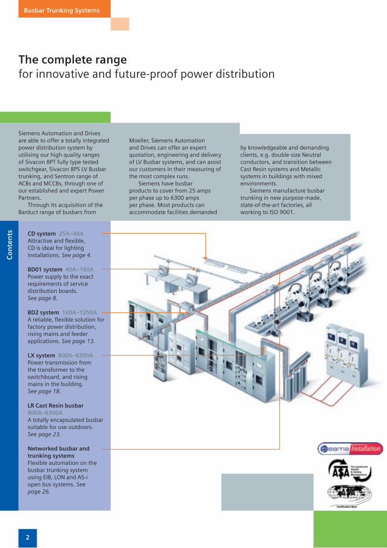
The complete rangefor innovative and future-proof power distribution
Busbar Trunking Systems
Siemens Automation and Drives are able to offer a totally integrated power distribution system by utilising our high quality ranges of Sivacon 8PT fully type tested switchgear, Sivacon 8PS LV Busbar trunking, and Sentron range of ACBs and MCCBs, through one of our established and expert Power Partners.
Through its acquisition of the Barduct range of busbars from
Moeller, Siemens Automation and Drives can offer an expert quotation, engineering and delivery of LV Busbar systems, and can assist our customers in their measuring of the most complex runs.
Siemens have busbar products to cover from 25 amps per phase up to 6300 amps per phase. Most products can accommodate facilities demanded
by knowledgeable and demanding clients, e.g. double-size Neutral conductors, and transition between Cast Resin systems and Metallic systems in buildings with mixed environments.
Siemens manufacture busbar trunking in new purpose-made, state-of-the-art factories, all working to ISO 9001.
BD2 system 160A–1250AA reliable, flexible solution for factory power distribution, rising mains and feeder applications. See page 13.
BD01 system 40A–160APower supply to the exact requirements of service distribution boards.See page 8.
LX system 800A–6300APower transmission from the transformer to the switchboard, and rising mains in the building. See page 18.
Networked busbar and trunking systemsFlexible automation on the busbar trunking system using EIB, LON and AS-i open bus systems. See page 26.
CD system 25A–40AAttractive and flexible, CD is ideal for lighting installations. See page 4.
LR Cast Resin busbar 800A–6300AA totally encapsulated busbar suitable for use outdoors.See page 23.
Co
nte
nts

2 3
Plus points in every respectbusbar offers advantages over cables
Busbar Trunking Systems
SIM
P L E Q U
I CK
SA
F EF L E X
I BL
E
Simpler in design
Busbar trunking systems are easier to design as the power distribution system can be planned just on the basis of the total connected load and the number and type of individual loads. The linear network structure with tap-offs to the load at regular intervals produces a clear system configuration, further simplifying engineering. By using angles, sets and tees to change direction or negotiate obstacles, busbar can conform to any shape of a building.
Safer, thanks to a high short-circuit rating and minimal combustive energy
Busbar trunking systems from Siemens offer clear safety advantages in terms of both short-circuit ratings and combustive energy. For example, BD2 A-250 busbar trunking systems have a combustive energy of just 1.32kWh/m, whereas for comparable cable installations (NYY 4 x 95/50mm2) this is 5.19kWh/m. Furthermore, Siemens busbar trunking systems are halogen-free and have a high short-circuit rating as standard. The short-circuit protection close to the load also simplifies trouble-shooting. Errors during assembly are practically eliminated thanks to safe, design-imposed connection sequences.
Quicker to install
Busbar trunking systems can reduce on-site installation times by up to 50% compared to cable installations. A single run of busbar can replace several runs of cable, along with their associated cable trays, junction boxes and fixings. No special tools are required. Siemens’
busbar systems are simple to secure and have wide fixing intervals
(busbars up to every 4m, cable every 1.5m),
further reducing installation times.
More flexible for
modification and expansion
Where a power distribution system
has to match changing requirements, busbars offer a
fast solution. As demand changes, tap off devices can be added or relocated with minimal disruption and downtime. The installation can be expanded and modified without difficulty. Flexibility is increased still further thanks to the wide range of tap-off units and system components available. Cost-intensive downtimes are eliminated or kept to a minimum. At all times the power distribution system ensures trouble-free operation with a high level of user friendliness and reliability.
Cable installation means higher combustive energy and more space.
Installation times are reduced as busbar is simple to secure, with wide fixing intervals.
With a cable installation, new loads need to be connected via an additional sub-distribution board or additional cables, involving more time and expense.
Busbar trunking systems enable additional supplies to be fitted simply by adding a tap-off unit to the nearest tap-off point.
4 5
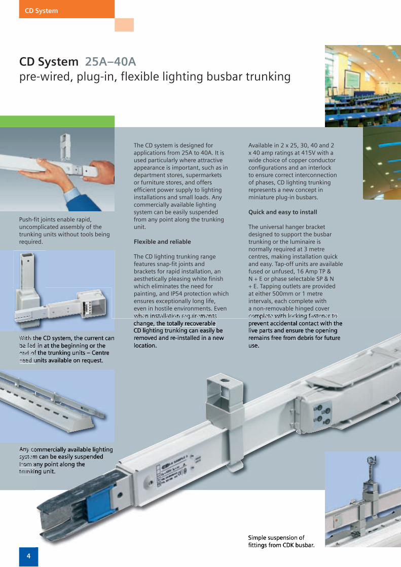
CD System 25A–40Apre-wired, plug-in, flexible lighting busbar trunking
CD System
Push-fi t joints enable rapid, uncomplicated assembly of the trunking units without tools being required.
With the CD system, the current can be fed in at the beginning or the end of the trunking units – Centre Feed units available on request.
Any commercially available lighting system can be easily suspended from any point along the trunking unit.
The CD system is designed for applications from 25A to 40A. It is used particularly where attractive appearance is important, such as in department stores, supermarkets or furniture stores, and offers effi cient power supply to lighting installations and small loads. Any commercially available lighting system can be easily suspended from any point along the trunking unit.
Flexible and reliable
The CD lighting trunking range features snap-fi t joints and brackets for rapid installation, an aesthetically pleasing white fi nish which eliminates the need for painting, and IP54 protection which ensures exceptionally long life, even in hostile environments. Even when installation requirements
Available in 2 x 25, 30, 40 and 2 x 40 amp ratings at 415V with a wide choice of copper conductor confi gurations and an interlock to ensure correct interconnection of phases, CD lighting trunking represents a new concept in miniature plug-in busbars.
Quick and easy to install
The universal hanger bracket designed to support the busbar trunking or the luminaire is normally required at 3 metre centres, making installation quick and easy. Tap-off units are available fused or unfused, 16 Amp TP & N + E or phase selectable SP & N + E. Tapping outlets are provided at either 500mm or 1 metre intervals, each complete with a non-removable hinged cover complete with locking fastener to
fi ttings from CDK busbar.
With the CD system, the current can be fed in at the beginning or the end of the trunking units – Centre Feed units available on request.
Any commercially available lighting system can be easily suspended from any point along the trunking unit.
when installation requirements change, the totally recoverable CD lighting trunking can easily be removed and re-installed in a new location.
complete with locking fastener to prevent accidental contact with the live parts and ensure the opening remains free from debris for future use.
Simple suspension of fi ttings from CDK busbar.
4 5
CD System
All lighting busbar trunking shall be approved manufacture and comply with degree of protection IP54 as defi ned in BSEN 60439. The current rating shall be defi ned on the drawings and schedules but will be typically 25A, 32A & 40A, 4pole or 8pole.
The system shall be totally enclosed. The trunking shall be suitable for use on a 400v 1, 2, 3, 4 phase (2, 3, 4 wire; PE = housing), 50/60 Hz supply and for the installation to meet the requirements of the IEE Wiring Regulations BS 7671 and BSEN 60439 parts 1 & 2. The enclosure shall be manufactured from zinc coated sheet steel, fi nished in white (similar to RAL 9002), rectangular in section with fl anges to the manufacturers standard suspension and luminaire support brackets. Phase and neutral conductors shall be tinned copper, of equal cross section, fully insulated and supported at both the tapping outlet positions and at each end of the trunking.
The lighting Busbar trunking shall be manufactured in 2 or 3 metre lengths each complete with a self-aligning electrical joint sleeve, interlocked to prevent phase reversal.
Tapping outlet positions shall be provided at 0.5 or 1 metre interval each complete with a non removable hinged cover complete with locking screw to ensure IP54 rating and preventing accidental contact with the live conductors.
All end feed units, end caps, joint sleeves and tap off units shall be manufactured from non-hygroscopic, self-extinguishing halogen-free insulating material and designed such that IP54 degree of protection is maintained.
Tap-off Units
Tap-offs shall be rated at 10A or 16A, 3pole or 5pole as defi ned on the drawings and schedules. They shall be plug-in and designed so as to permit phase selection on site by inserting of prewired contact blocks into the appropriate positions. Fused or unfused tap-off units shall be provided as required.
The lighting trunking shall be Siemens CDK, Barduct brand or equal and approved.
Easy quick joint designed for time-
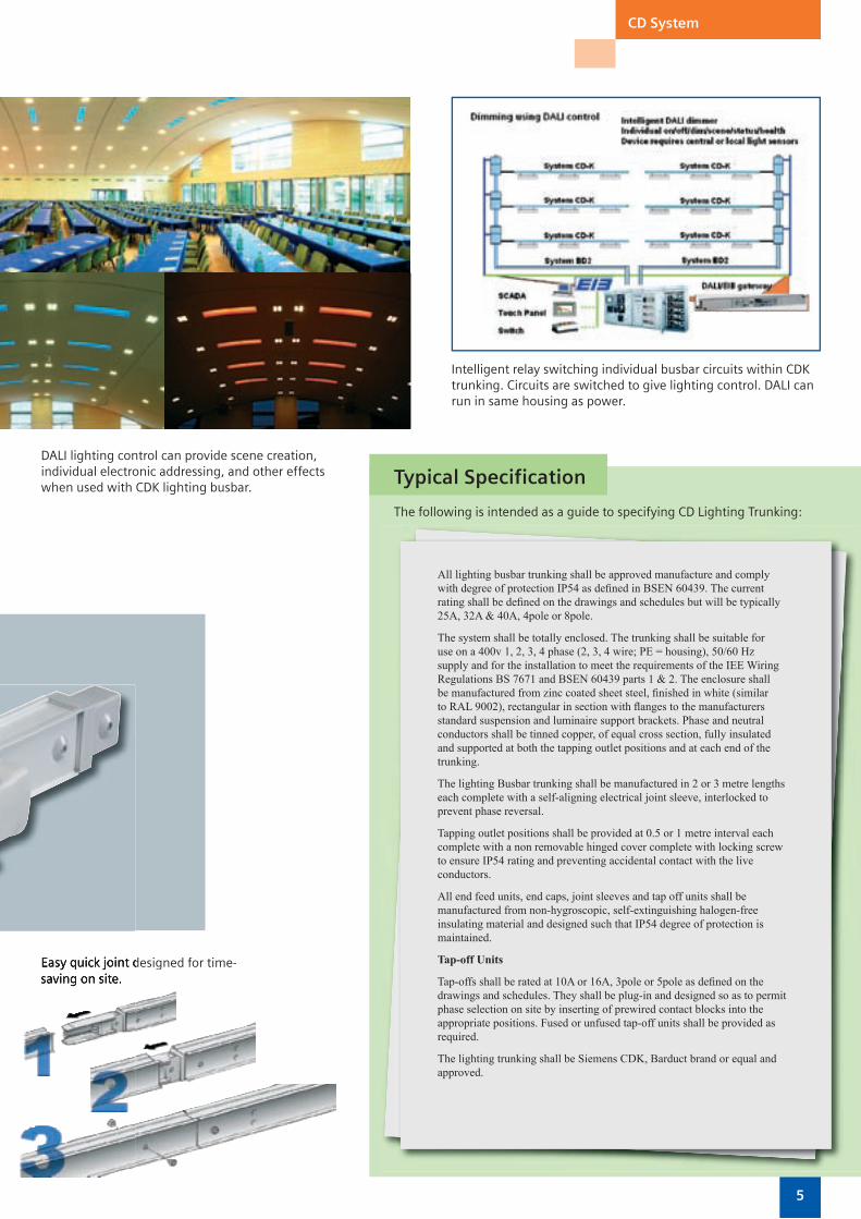
DALI lighting control can provide scene creation, individual electronic addressing, and other effects when used with CDK lighting busbar.
Intelligent relay switching individual busbar circuits within CDK trunking. Circuits are switched to give lighting control. DALI can run in same housing as power.
Typical Specification
The following is intended as a guide to specifying CD Lighting Trunking:
Easy quick joint designed for time-saving on site.

6 7
CD System
Technical Data and Part Numbers for CD Busbar TrunkingCurrent Rating A 30 30 30 2 x 25 40 40 40 2 x 40
Product Reference (CD-K-…) 1302 1303 1304 2254 1402 1403 1404 2404
Ambient temperature (min/max) ºC -5ºC to +40ºC
Degree of protection IP54; IEC/EN 60529
Mounting Edgewise, with tap-off points on the side
ConductorsRated Operational Voltage Ue V~ 400 400 400 400 400 400 400 400
Frequency Hz 50–60 50–60 50–60 50–60 50–60 50–60 50–60 50–60
Rated Current Ie therm. Rated current at max. 40ºC and 35ºC averaged over 24 hours
Amps 30 30 30 2 x 25 40 40 40 2 x 40
Conductor impedance at 50Hz and 20ºC busbar temperature
Resistance R20 mΩ/m 5.79 5.79 5.79 4.56 3.55 3.55 3.55 3.69
Reactance X20 mΩ/m 0.26 0.26 0.26 0.15 0.40 0.40 0.40 0.13
Impedance Z720 mΩ/m 5.80 5.80 5.80 4.56 3.57 3.57 3.57 3.69
Conductor impedance in the event of a fault
AC Resistance RF mΩ/m 8.24 8.24 8.24 7.50 5.61 5.61 5.61 4.17
Reactance XF mΩ/m 0.44 0.44 0.44 0.32 0.80 0.80 0.80 0.40
Impedance ZF mΩ/m 8.25 8.25 8.25 7.51 5.67 5.67 5.67 4.18
Zero Impedance tested to IEC 60 909, DIN VDE 0102
Resistance R0 Phase to N mΩ/m 24.24 24.24 24.24 18.59 14.85 14.85 14.85 14.33
Reactance X0 Phase to N mΩ/m 1.77 1.77 1.77 0.82 0.99 0.99 0.99 0.78
Impedance Z0 Phase to N mΩ/m 24.30 24.30 24.30 18.61 14.88 14.88 14.88 14.33
Resistance R0 Phase to PE mΩ/m 12 12 12 13.49 9.87 9.87 9.87 5.15
Reactance X0 Phase to PE mΩ/m 1.8 1.8 1.8 0.82 1.02 1.02 1.02 0.74
Impedance Z0 Phase to PE mΩ/m 12.13 12.13 12.13 13.52 9.92 9.92 9.92 5.21
Trunking Weight kg/m 0.75 0.78 0.81 1.06 0.78 0.83 0.88 1.22
Short Circuit RatingRated peak withstand Ipk kA 2.4 2.4 2.4 3 3.6 3.6 3.6 3.6
Rated short time withstand current Icw (t=1 s) kA 0.56 0.56 0.56 0.69 0.85 0.85 0.85 0.85
Rated short-time withstand current Icw (t=0.1 s) kA 1.6 1.6 1.6 2 2.4 2.4 2.4 2.4
Number of active conductors 2 3 4 2 x 4 2 3 4 2 x 4
Terminal Capacity
L1, L2, L3 mm2 3.2 3.2 3.2 4 5 5 5 5
N mm2 3.2 3.2 3.2 4 5 5 5 5
PE (enclosure) Cu mm2 11 11 11 11 11 11 11 11
Conductor Material Cu Cu Cu Cu Cu Cu Cu Cu
Tap-off PlugsTap-off point Offset every 0.5 m, 1 m or 0.5 m on each side; max. 16 A
Tap-off plug 3- and 5-pole; with or without permanently attached cable; with or without fuse holders for 8.5 mm x 31.5 mm; type gG (IEC) and type gL (VDE) fast cylinder fuses.All tap-off plugs are of utilization category AC-20B to IEC/EN 60 947-3.The PE operates as an early-make contact during connection, and as a late-break contact during removal of the tap-off plug.
Terminal CapacitiesDesignation Type L1, L2, L3 N PE
Min mm2 Max mm2 Min mm2 Max mm2 Min mm2 Max mm2
Entry Feeder Unit CD-K-…-EA 2.5 6 (f) 2.5 6 (f) 2.5 6 (f)
(Complete with end cap) 10 (st, so) 10 (st, so) 10 (st, so)
Entry Feeder Unit CD-K-…-EE 2.5 6(f) 2.5 6(f) 2.5 (6(f)
10 (st, so) 10 (st, so) 10 (st, so)
Notes so = solid, st = stranded, f = flexible with ferrule
Suspension Bracket CD-B
6 7
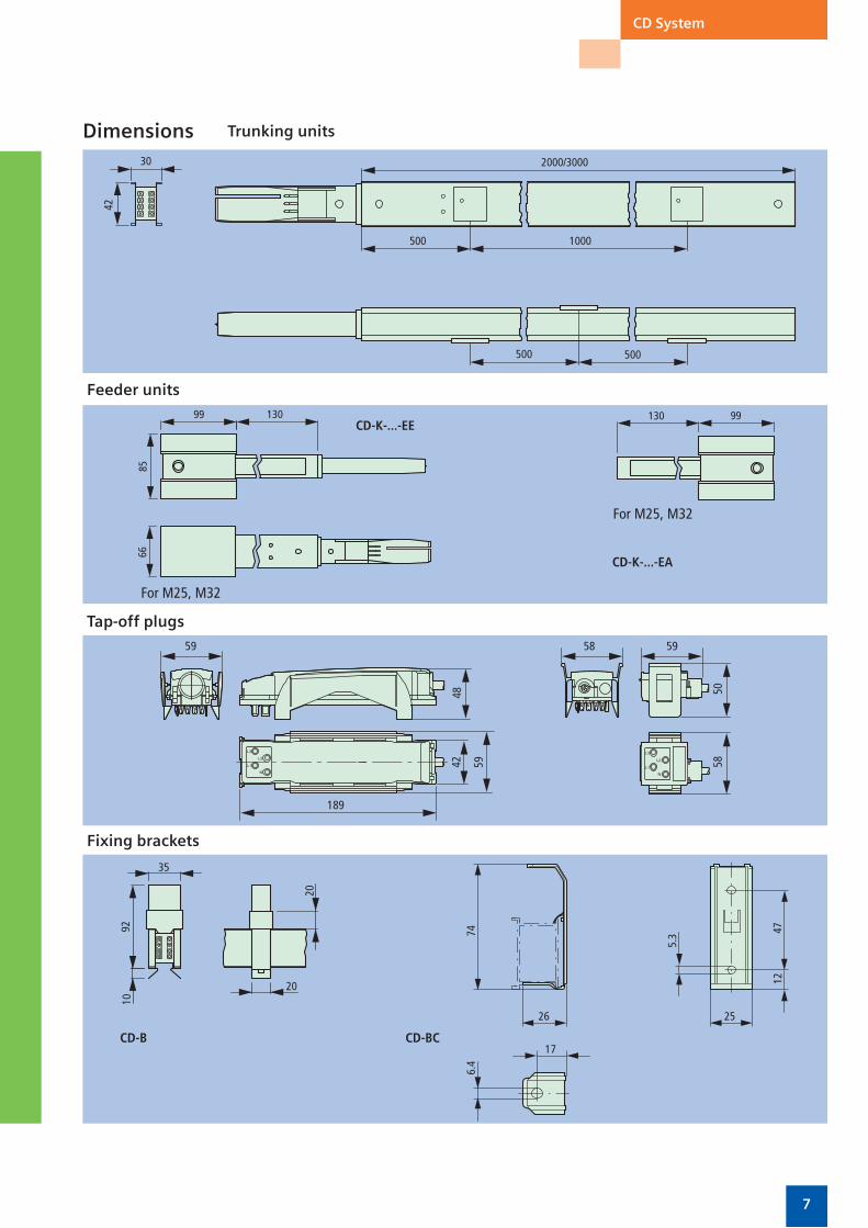
CD System
Dimensions
Feeder units
Tap-off plugs
Fixing brackets
CD-B CD-BC
CD-K-...-EE
CD-K-...-EA
Trunking units

8 9
BD01 System 40A–160Asimple and safe distribution of power
BD01 System
The feeder unit can be fi tted to any junction point.
Flexible in every direction.
Energy always where it’s needed – adapted to the different requirements of workshop operation.
The BD01 system is designed for applications from 40A to 160A. It is primarily used in trade and industry to provide a safe power supply for small loads and to feed Siemens’ CD lighting trunking.
The asymmetrical design of the connection points ensures fault-free installation of the trunking units. The design imposed fi tting of the tap-offs on the trunking unit ensures a high degree of safety for operating personnel. The tap-off points only open automatically when the tap-off units are fi tted. They close automatically when the tap-off units are removed.
Flexible power supply
The power supply for the BD01 system is provided via end or centre feeder units as required. These can be positioned at junction points on the trunking run and ensure fl exibility to match changing site conditions. The fl exible junction unit enables the run to be adapted to any building layout.
Tap-off units are available in four sizes for equipping with devices of your choice or ready-fi tted with protective devices (fuses, MCBs) or protective devices combined with CEE sockets.
Combined with pre-wired ancillary equipment units, the result is a wide range of solutions for many different applications. Furthermore, the galvanised and painted enclosure of the trunking unit ensures optimum protection against corrosion.
Simple design
primarily used in trade and industry
small loads and to feed Siemens’ CD
system is provided via end or centre
Just one size for fi ve different current ratings means minimum stock-holding and uncomplicated design. The variable mounting position – edgewise or fl at – ensures straightforward engineering without de-rating.
The well thought-out BD01 system, with the mechanical and electrical connection of the trunking units accomplished in a single operation, saves on installation time and thus reduces assembly costs.
8 9
BD01 System
All busbar trunking shall be of approved manufacture and comply with degree of protection IP54 as defi ned in BSEN 60439 when edgewise (tap-off points at the side and bottom) and IP50 when fl at (tap-off points on the top). The current rating shall be defi ned on the drawings and schedules but will be typically 40A to 160A.
The busbar shall be designed and manufactured to comply with BSEN 60439 parts 1 & 2. For use on a 400v, 3phase 4wire (PE = Housing), 50/60Hz supply, and capable of withstanding prospective fault levels as detailed on the drawing schedules.
The busbar trunking shall be manufactured in 2 or 3 metre lengths. The enclosure shall be manufactured from pale grey (RAL 7035) painted galvanised sheet steel and is the protective earth conductor. The busbar trunking shall have solid conductors with silver-plated aluminium and copper connection points at all tap off outlets and joint positions. Tap-off outlets shall be spaced at 0.5 and 1 metre distance and shall have automatic opening and closing shutters. They will also ensure correct polarity is maintained. The joint section shall provide electrical & mechanical connection by four screws. The joint section shall absorb any differential expansion between the trunking and the conductors
When a change in direction, rating or termination occurs in a busbar run, manufacturer’s purpose made fi ttings such as junction units, feeder units, end fl anges and centre feeds shall be used.
Where detailed on the drawings and schedules interlocking coding sets shall be installed into the tap-off outlets and tap-off units to provide non- interchange ability of tap-off units to non- designated tap-off outlets.
Tap-off Units
Tap-off units shall be plug-in type suitable to accept HRC fuses, MCBs, DIN rail mounted devices and socket outlets as detailed on the drawings and schedules.
The enclosure shall be constructed from anodised aluminium and/or insulation material, complying to the degree of protection IP54, as defi ned in BSEN 60439.
The earth connection of the tap-off unit shall provide the opening of the automatic shutter and make before and break after the live connections are made.
Where required tap-off units shall be extendible to allow additional components to be installed onto the internal DIN rail.
The busbar trunking system shall be Siemens BD01, Barduct brand or equal and approved.
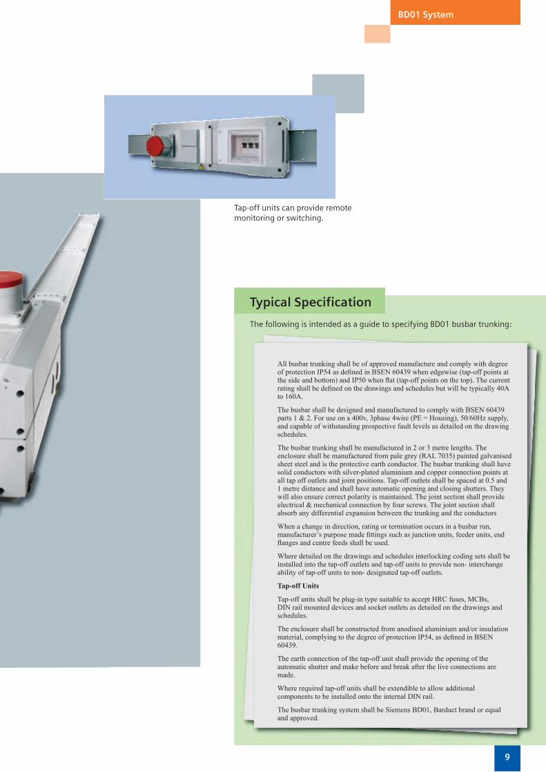
Tap-off units can provide remote monitoring or switching.
Typical Specification
The following is intended as a guide to specifying BD01 busbar trunking:

10 11
BD01 System
Technical Data and Part Numbers for BD01 Busbar Trunking
Product Reference – Current Rating BD01-40 BD01-63 BD01-100 BD01-125 BD01-160
Current paths
Rated Operational Voltage Ue V~ 400 400 400 400 400
Frequency Hz 50–60 50–60 50–60 50–60 50–60
Rated Current Ie therm. Rated current at max. 40ºC and 35ºC averaged over 24 hours
A 40 63 100 125 160
Conductor impedance at 50Hz and 20ºC busbar temperature
Resistance R20 mΩ/m 3.960 1.936 0.938 0.910 0.578
Reactance X20 mΩ/m 0.280 0.324 0.286 0.300 0.273
Impedance Z720 mΩ/m 3.970 1.968 0.994 1.000 0.642
Conductor impedance in the event of a fault
AC Resistance RF mΩ/m 5.991 4.128 2.841 2.420 2.189
Reactance XF mΩ/m 1.396 1.248 1.186 0.940 0.973
Impedance ZF mΩ/m 6.151 4.312 3.078 2.600 2.395
Zero Impedance tested to IEC 60 909, DIN VDE 0102
Resistance R0 Phase to N mΩ/m 15.904 7.911 4.115 3.810 3.167
Reactance X0 Phase to N mΩ/m 2.128 2.058 1.797 1.630 1.656
Impedance Z0 Phase to N mΩ/m 1.045 8.175 4.490 4.140 3.574
Resistance R0 Phase to PE mΩ/m 10.086 8.565 6.648 5.430 5.343
Reactance X0 Phase to PE mΩ/m 2.909 3.338 3.067 2.320 2.355
Impedance Z0 Phase to PE mΩ/m 10.498 9.183 7.322 5.910 5.839
Short Circuit RatingRated peak withstand Ipk kA 2.55 6.30 15.30 15.30 15.30
Rated short time withstand current Icw (t=1 s) kA 0.58 1.15 2.50 2.50 2.50
Rated short-time withstand current Icw (t=0.1 s) kA 1.70 4.20 9.00 9.00 9.00
Number of active conductors 4 4 4 4 4
Conductor cross-section
L1, L2, L3 mm2 7.9 15.7 34.1 34.1 34.1
N mm2 7.9 15.7 34.1 34.1 34.1
PE (enclosure) Cu mm2 20.0 20.0 20.0 20.0 20.0
Conductor Material Al Al Al Al Cu
Max. interval between trunking unitsupports at normal mechanical load
edgewise m 3 3 3 3 3
flat m 1.5 1.5 1.5 1.5 1.5
Combustive Energy kWh/m 0.76 0.76 0.76 0.76 0.76
Trunking Weight kg/m 1.45 1.55 1.75 1.75 2.65
Tap-off UnitsRated Operational Voltage Ue V 230 or 400
Rated Current Ie max. A 63
Switching capacity of the built-in switch-disconnector AC-20B
Terminal Capacities L1, L2, L3 N PE
Type min mm2 max mm2 min mm2 max mm2 min mm2 max mm2
Feeder units BD01-E 6 (e, m) 50 (m) 6 (e, m) 50 (m) 6 (e, m) 50 (m)
BD01-160-E 25 (m) 95 (m) 25 (m) 95 (m) 16 (m) 50 (m)
Tap-off units BD01-AK01X/ZS 0.75 (f, st) 10 (f, so, st) 0.75 (f, st) 10 (f, so, st) 0.75 (f, st) 10 (f, so, st)
BD01-AK02X/ZS3 0.75 (f, st) 10 (f, so, st) 0.75 (f, st) 10 (f, so, st) 0.75 (f, st) 10 (f, so, st)
BD01-AK02M0/A163 0.75 (so, st) 16 (so) 0.75 (f, st) 10 (f, so, st) 0.75 (f, st) 10 (f, so, st)
BD01-AK02M0/A323 0.75 (so, st) 16 (so) 0.75 (f, st) 10 (f, so, st) 0.75 (f, st) 10 (f, so, st)
BD01-AK1M1/A101 0.75 (so, st) 16 (so) 0.75 (so, f) 2.5 (so, f) 0.75 (so, f) 2.5 (so, f)
BD01-AK1M1/A161 0.75 (so, st) 17 (so) 0.75 (so, f) 2.5 (so, f) 0.75 (so, f) 2.5 (so, f)
BD01-AK1M1/A321 0.75 (so, st) 18 (so) 0.75 (so, f) 2.5 (so, f) 0.75 (so, f) 2.5 (so, f)
BD01-AK1M1/A... 0.75 (so, st) 16 (so) 0.75 (f, st) 10 (f, so, st) 0.75 (so, st) 16 (so)
BD01-AK1M1/A...N 0.75 (so, st) 16 (so) 0.75 (so, st) 16 (so) 0.75 (so, st) 16 (so)
BD01-AK1X/S14 0.50 (f, st) 4 (so) 0.75 (f, st) 10 (f, so, st) 0.75 (so, st) 16 (so)
Notes: BD01-AK1X/S18 0.50 (f, st) 16 (f, so, st) 0.75 (f, st) 10 (f, so, st) 0.75 (so, st) 16 (so)
BD01-AK1X/GB... 0.75 (so, st) 16 (so) 0.75 (f, st) 10 (f, so, st) 0.75 (so, st) 16 (so)
so = solid BD01-AK2X/F1451 0.75 (so, st) 16 (so) 0.75 (f, st) 10 (f, so, st) 0.75 (so, st) 16 (so)
st = stranded BD01-AK2X/S27 0.75 (f, st) 10 (f, so, st) 0.75 (f, st) 10 (f, so, st) 0.75 (so, st) 16 (so)
f = flexible with ferrule BD01-AK2HX/S33 1.50 (f, st) 25 (f, st) 0.75 (f, st) 10 (f, so, st) 0.75 (so, st) 16 (so, st)

10 11
BD01 System
Continued overleaf
Dimensions Trunking units
Flexible junction units
BD01…R
Type l l1 l2
BD01-…-R1 500 165 316
BD01-…-R2 1000 665 –
l aNo of
tap-off points
2000500 4
1000 2
3000500 6
1000 3BD01-…
Note These are the dimensions for some of the more popular items in the BD01 range. For details of the full range please refer to Siemens’ Power Distribution Catalogue (LV70).
12 13
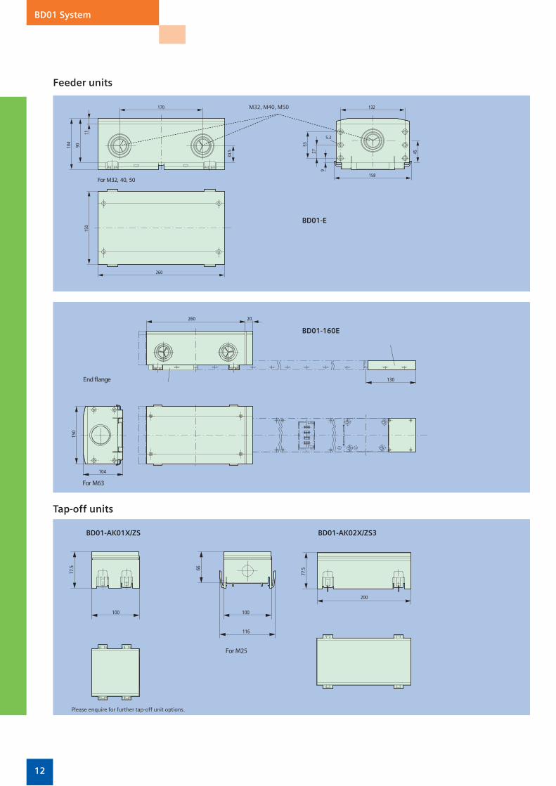
BD01 System
Feeder units
BD01-E
BD01-160E
Tap-off units
BD01-AK01X/ZS BD01-AK02X/ZS3
M32, M40, M50
Please enquire for further tap-off unit options.
12 13
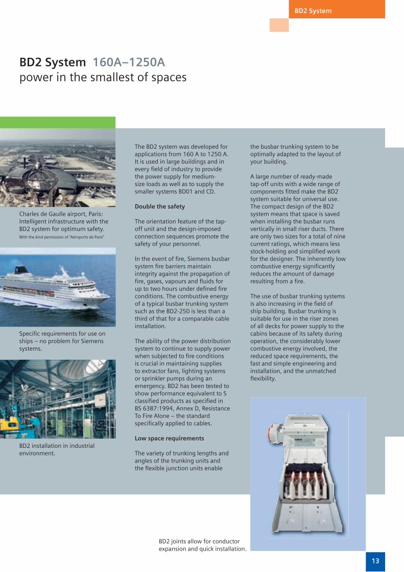
BD2 System 160A–1250Apower in the smallest of spaces
BD2 System
Charles de Gaulle airport, Paris: Intelligent infrastructure with the BD2 system for optimum safety.With the kind permission of “Aéroports de Paris”
Specifi c requirements for use on ships – no problem for Siemens systems.
The BD2 system was developed for applications from 160 A to 1250 A. It is used in large buildings and in every fi eld of industry to provide the power supply for medium-size loads as well as to supply the smaller systems BD01 and CD.
Double the safety
The orientation feature of the tap-off unit and the design-imposed connection sequences promote the safety of your personnel.
In the event of fi re, Siemens busbar system fi re barriers maintain integrity against the propagation of fi re, gases, vapours and fl uids for up to two hours under defi ned fi re conditions. The combustive energy of a typical busbar trunking system such as the BD2-250 is less than a third of that for a comparable cable installation.
The ability of the power distribution system to continue to supply power when subjected to fi re conditions is crucial in maintaining supplies to extractor fans, lighting systems or sprinkler pumps during an emergency. BD2 has been tested to show performance equivalent to S classifi ed products as specifi ed in BS 6387:1994, Annex D, Resistance To Fire Alone – the standard specifi cally applied to cables.
Low space requirements
The variety of trunking lengths and angles of the trunking units and the fl exible junction units enable
the busbar trunking system to be optimally adapted to the layout of your building.
A large number of ready-made tap-off units with a wide range of components fi tted make the BD2 system suitable for universal use. The compact design of the BD2 system means that space is saved when installing the busbar runs vertically in small riser ducts. There are only two sizes for a total of nine current ratings, which means less stock-holding and simplifi ed work for the designer. The inherently low combustive energy signifi cantly reduces the amount of damage resulting from a fi re.
The use of busbar trunking systems is also increasing in the fi eld of ship building. Busbar trunking is suitable for use in the riser zones of all decks for power supply to the cabins because of its safety during operation, the considerably lower combustive energy involved, the reduced space requirements, the fast and simple engineering and installation, and the unmatched fl exibility.
BD2 joints allow for conductor expansion and quick installation.
BD2 installation in industrial environment.

14 15
BD2 System
Branch and junction units permit optimum adaptation to building structures.
All busbar trunking shall be of approved manufacture and the current ratings detailed on the drawings and schedules – typically from 160A to 1250A, and complying to degree of ingress protection IP52 defi ned in BSEN 60439 and IP54 with accessories.
The busbar shall be designed and manufactured to comply with BSEN 60439 parts 1 & 2. For use on a 690v, 3phase 5wire (3L, N or half N, PE or half PE), 50/60Hz supply, and capable of withstanding prospective fault levels as detailed on the drawing schedules.
The busbar trunking shall be manufactured in 1.25, 2.25 & 3.25 metre lengths or optional lengths from 0.5 up to 3.24 metres. The enclosure shall be manufactured from pale grey (RAL 7035) painted galvanised sheet steel. The busbar trunking shall have solid conductors with nickel-plated and tinned aluminium or copper, with insulated tap-off outlets and busbar supports.
Tap-off outlets shall be spaced at 0.5 and 1 metre distance and shall have automatic opening and closing shutters. They will also ensure correct polarity is maintained. The joint section shall provide electrical and mechanical connection by four screws. The joint section shall absorb any differential expansion between the trunking and the conductors
When a change in direction, rating or termination occurs in a busbar run, manufacturer’s purpose-made fi ttings such as L junction units, feeder units, end fl anges and centre feeds shall be used.
When supplied as Rising Main busbar suitable fi re barriers must be fi tted which meet the requirements of BSEN 60439 part 2 and of fi re resistance Class S120.
Tap-off Units
Tap-off units shall be plug-in type suitable to accept HRC and BS fuses, MCBs, MCCBs, Switch Disconnectors, DIN rail mounted devices and socket outlets as detailed on the drawings and schedules.
The enclosure shall be constructed from painted steel and/or insulation material, complying to the degree of protection IP54, as defi ned in BSEN 60439.
The earth connection of the tap-off unit shall be provide the opening of the automatic shutter and make before and break after the live connections are made.
Where required, tap-off units shall be extendible to allow additional components to be installed onto the internal DIN rail.
The busbar trunking system shall be Siemens BD2, Barduct brand or equal and approved.
Typical Specification
The following is intended as a guide to specifying BD2 busbar trunking:

14 15
BD2 System
Technical Data for BD2A 5 Bar, Aluminium Conductors Load Distribution Factor = 0.5
Rated Current A 160 250 315 400 500 630 800 1000
Rated Voltage VAC 690 690 690 690 690 690 690 690
Voltage Drop, Balanced Load mV/A/m pf = 0.7 0.440 0.330 0.300 0.210 0.120 0.130 0.090 0.080
pf = 0.8 0.470 0.360 0.320 0.210 0.120 0.130 0.100 0.080
pf = 0.9 0.500 0.380 0.340 0.210 0.130 0.140 0.100 0.070
pf = 1.0 0.490 0.380 0.330 0.190 0.120 0.130 0.080 0.060
Conductor Characteristics
R mΩ/m at end temperature 0.564 0.438 0.383 0.215 0.135 0.149 0.098 0.066
X mΩ/m at end temperature 0.158 0.111 0.112 0.122 0.056 0.057 0.057 0.057
Z mΩ/m at end temperature 0.586 0.452 0.399 0.247 0.146 0.159 0.114 0.088
Protective Conductor
R0 mΩ/m 1.638 1.279 1.225 1.059 0.492 0.492 0.438 0.408
X0 mΩ/m 0.606 0.516 0.524 0.518 0.299 0.303 0.280 0.273
Weight kg/M 5.3 5.8 6.6 7.5 12.3 12.3 12.4 15.8
IP Rating Standard IP 52 IP 52 IP 52 IP 52 IP 52 IP 52 IP 52 IP 52
Optional IP 54 IP 54 IP 54 IP 54 IP 54 IP 54 IP 54 IP 54
Dimensions mm 167x68 167x68 167x68 167x68 167x126 167x126 167x126 167x126
Short Time Rating kA for 1 sec 5.5 10 14 16 21 26 32 34
Prospective Short Circuit Rating kA 17 32 36 40 59 64 84 90
Number of Trunkings 1 1 1 1 1 1 1 1
Technical Data for BD2C 5 Bar, Copper Conductors Load Distribution Factor = 0.5
Rated Current A 160 250 315 400 500 630 800 1000 1250
Rated Voltage VAC 690 690 690 690 690 690 690 690 690
Voltage Drop, Balanced Load mV/A/m pf = 0.7 0.300 0.330 0.300 0.220 0.120 0.120 0.070 0.070 0.060
pf = 0.8 0.310 0.350 0.320 0.230 0.120 0.130 0.070 0.070 0.060
pf = 0.9 0.320 0.360 0.340 0.230 0.130 0.140 0.070 0.070 0.050
pf = 1.0 0.290 0.330 0.330 0.210 0.120 0.130 0.060 0.060 0.040
Conductor Characteristics
R mΩ/m at end temperature 0.333 0.383 0.383 0.239 0.136 0.151 0.065 0.068 0.041
X mΩ/m at end temperature 0.157 0.158 0.112 0.115 0.053 0.053 0.053 0.053 0.054
Z mΩ/m at end temperature 0.368 0.414 0.399 0.266 0.146 0.160 0.084 0.086 0.068
Protective Conductor
R0 mΩ/m 1.027 1.139 1.065 0.956 0.473 0.470 0.258 0.270 0.174
X0 mΩ/m 0.641 0.529 0.507 0.507 0.274 0.277 0.265 0.249 0.265
Weight kg/M 7.3 7.5 8.0 9.5 15.6 15.6 18.9 25.1 37.6
IP Rating Standard IP 52 IP 52 IP 52 IP 52 IP 52 IP 52 IP 52 IP 52 IP52
Optional IP 54 IP 54 IP 54 IP 54 IP 54 IP 54 IP 54 IP 54 IP54
Dimensions mm 167x68 167x68 167x68 167x68 167x126 167x126 167x126 167x126 167x126
Short Time Rating kA for 1 sec 5.5 10 14 16 21 26 32 34 34
Prospective Short Circuit Rating kA 17 32 36 40 59 64 84 90 90
Number of Trunkings 1 1 1 1 1 1 1 1 1
Dimensions
160 to 400 A 500 to 1250 A
N L1 L2 L3 PE
167
68
N L1 L2 L3 PE
126
167
160–400A 500–1250A

16 17
BD2 System
330
c
220307 (557)
16716
3
n × 500 (1000) c
70
x =
360–
1250
G* = 85°–175°
70
y = 360–1250
c
x =
360–
1250
y = 360–1250
G* = 85°–175°
c
c1
c2
163
200
307
295
4 × 6512.5
108.
518
3.5
123
Dimensions Straight trunking units
L-junction units
223
247.5
191
924
0
100
285
223
253
14 × 9
308
332.5
191
308
325
338
100
370
Cabling boxes Distribution feeder unit
centre of clamp terminal
Rated current (A)
c(mm)
160–400 68
500–1250 126
BD2.-…-LR…(-G*), BD2.-…-LL…(-G*) BD2.-…-LV…(-G*), BD2.-…-LH…(-G*)
BD2.-400(1000)-VE
Note These are the dimensions for some of the more popular items in the BD2 range. For details of the full range please refer to Siemens’ Power Distribution Catalogue (LV70).
BD2.-…-…
BD2-400-KR (BD2.-400-EE) BD2-1000-KR (BD2.-1000-EE)
x

16 17
BD2 System
9
40
64
74
143.
5
100
20
270
3
14 × 9
167
245
270
290
300
250
478
563
200
75
4064
105
200
219
395
420
440
85167
423
100
387.5
605
687
200
9 14 × 9
End feeder units
Unistrut mounting bracket
169
199
33 c1
34
15
100
7.2
7.2
11
c
Fixing bracket
Tap-off units
BD2.-250-EE BD2.-400-EE
20
101
50
9
5035
4
77
314 7
205
440
BD2-AK2X/GB323 32ABD2-AK2X/GB633 63A
For M32
For M25, 32, 40
For M20
20
101
50
9
5047
4
434 7
BD2-AK3X/GB1003 100A
For M32For M25, 40, 63
For M20
Rated current (A)
c(mm)
c1(mm)
160–400 86.5 48
500–1250 144.5 77
BD2-BVVBD2-…-BB
x
x
320
240
37
172
Quick and easy direct mounting on Unistrut

18 19
LX System 800A–6300Aless weight, more power
LX System
The LX system with its ‘sandwich’ construction is designed for applications from 800A to 6300A. It is used in multi-storey buildings and wherever the fl exible transportation of large amounts of power is required.
The high degree of protection to IP55 ensures the safe distribution of power even in challenging ambient conditions.
The tap-off units have an orientation feature, which ensures fault-free installation due to the design-imposed fi tting sequence. This, together with the automatic protective mechanism at the tap-off points, ensures a high degree of protection from accidental contact for operating personnel.
Reliability in sensitive environments
Flexibility in every position
The electrical load bearing capacity of the LX system is not affected by its installation position. This enables optimum fl exibility where busbar run routing is concerned. The distortion resistant aluminium enclosure is low in weight and highly resistant to chemical and atmospheric infl uences.
Compact and light
The compact, low impedance ‘sandwich’ construction minimises voltage drops, so enabling the cost effective transmission of large amounts of power, even over long distances, whether installed horizontally or vertically.
Rapid connection reduces assembly times, as does the low weight of the LX busbar system.
Reliability of supply was a key consideration when over 1km of LX busbar was installed at the headquarters of Swiss Re in London.
The conductor confi gurations with double N conductors and clean earth ensure an overload free neutral conductor even with imbalanced loads. Susceptible loads such as computers are not put at risk by earth faults to the enclosure if they are connected to the clean earth.
For full selection and technical details of the Siemens LX Busbar Trunking System, please request a copy of the LX Catalogue (LV72T – 2004).
Reliability of supply was a key consideration when over 1km of LX busbar was installed at the headquarters of Swiss Re in London.

18 19
LX System
Optimum matching to building layouts.
Rapid, safe mounting of structural elements.
All busbar trunking shall be of approved manufacture and the current ratings detailed on the drawings and schedules – typically from 800A to 6300A, and complying with degree of ingress protection IP54 defi ned in BSEN 60439.
The system shall be totally enclosed and low impedance sandwich construction. The trunking shall be suitable for use on 690v 50Hz supply and available in various confi gurations including 3 phase and Neutral, double neutral, earth and/or clean earth (with a maximum of six conductors). It shall meet the requirements of the IEE Wiring Regulations BS 7671 and BSEN 60439 parts 1 & 2. The enclosure shall be manufactured from aluminium fi nished in pale grey RAL 7035, prepared to accept manufacturer’s standard suspension hangers and support brackets. Phase and neutral conductors shall be nickel and tin plated aluminium or copper, of equal cross-section fully insulated.
The busbar trunking current rating must be equal in all installation positions (fl at, edge or vertical). A derating in any position is not acceptable.
The busbar trunking shall be manufactured in different lengths up to 3 metres either as feeder or distribution busbar. Each plug in joint located at the end of each busbar length will be equipped with a self-torquing sheer head single torque bolt joint block.
Manufacturers standard junction units shall be supplied as standard, including elbows, knees, T-sections, offsets, expansion fi ttings, and end caps. Further standard components must be available such as cable feeder boxes, transformer connections and panel fl ange connections.
For distribution busbar, tapping outlet positions shall be provided as required with up to fi ve outlets on each side of a 3 metre length of busbar. Each outlet shall have a cover complete with seal facility to ensure IP54 rating and preventing accidental contact with live parts.
All plastic parts (like tapping outlets) shall be manufactured from non-hygroscopic self-extinguishing halogen-free insulating material and designed such that IP54 degree of protection is maintained.
When supplied as Rising Main busbar the construction should be suitable to provide fi re barrier protection to meet the requirements of BSEN 60439 part 2 and of fi re resistance Class S120.
Tap-off Units
When supplied as Rising Main busbar suitable fi re barriers must be fi tted which meet the requirements of BSEN 60439 part 2 and of fi re resistance Class S120.
Tap-off units shall be plug-in type up to 630amps and fi x mounted from 800A to 1250A. Incorrect mounting shall be prevented by an interlocking mechanism. The tap-off units shall be equipped with either fused switch or MCCB. The short circuit rating shall be up to 100kA at 415v 50Hz.
The enclosure shall be constructed from painted steel and/or insulation material, complying to the degree of protection IP54, as defi ned in BSEN 60439.
The earth connection of the tap-off unit shall provide the opening of the automatic shutter and make before and break after the live connections are made.
The busbar trunking system shall be Siemens LX, Barduct brand or equal and approved.
Typical Specification
The following is intended as a guide to specifying LX busbar trunking:
Engineered fl anged connection into any make of switchgear, and fully type-tested connection available for Siemens 8PT Switchgear.
20 21
LX System
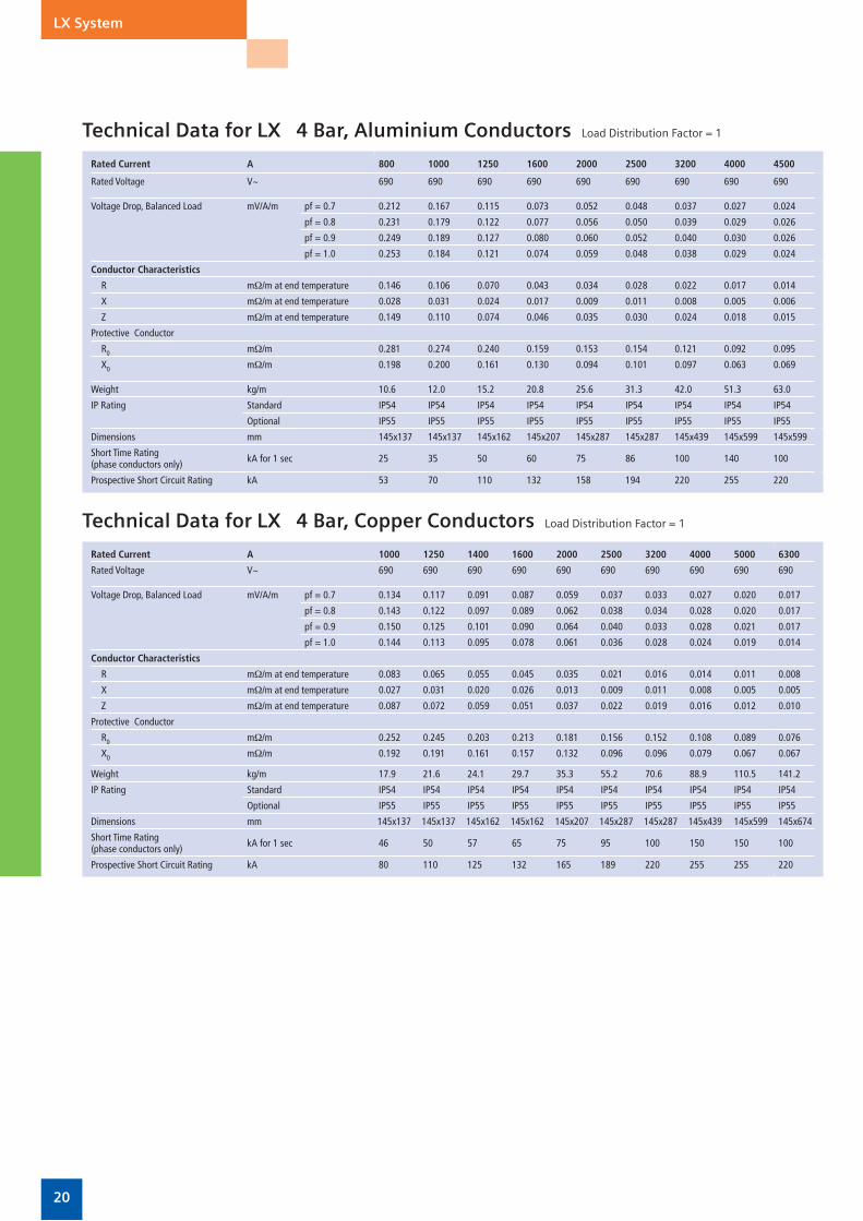
Technical Data for LX 4 Bar, Aluminium Conductors Load Distribution Factor = 1
Rated Current A 800 1000 1250 1600 2000 2500 3200 4000 4500
Rated Voltage V~ 690 690 690 690 690 690 690 690 690
Voltage Drop, Balanced Load mV/A/m pf = 0.7 0.212 0.167 0.115 0.073 0.052 0.048 0.037 0.027 0.024
pf = 0.8 0.231 0.179 0.122 0.077 0.056 0.050 0.039 0.029 0.026
pf = 0.9 0.249 0.189 0.127 0.080 0.060 0.052 0.040 0.030 0.026
pf = 1.0 0.253 0.184 0.121 0.074 0.059 0.048 0.038 0.029 0.024
Conductor Characteristics
R mΩ/m at end temperature 0.146 0.106 0.070 0.043 0.034 0.028 0.022 0.017 0.014
X mΩ/m at end temperature 0.028 0.031 0.024 0.017 0.009 0.011 0.008 0.005 0.006
Z mΩ/m at end temperature 0.149 0.110 0.074 0.046 0.035 0.030 0.024 0.018 0.015
Protective Conductor
R0 mΩ/m 0.281 0.274 0.240 0.159 0.153 0.154 0.121 0.092 0.095
X0 mΩ/m 0.198 0.200 0.161 0.130 0.094 0.101 0.097 0.063 0.069
Weight kg/m 10.6 12.0 15.2 20.8 25.6 31.3 42.0 51.3 63.0
IP Rating Standard IP54 IP54 IP54 IP54 IP54 IP54 IP54 IP54 IP54
Optional IP55 IP55 IP55 IP55 IP55 IP55 IP55 IP55 IP55
Dimensions mm 145x137 145x137 145x162 145x207 145x287 145x287 145x439 145x599 145x599
Short Time Rating(phase conductors only) kA for 1 sec 25 35 50 60 75 86 100 140 100
Prospective Short Circuit Rating kA 53 70 110 132 158 194 220 255 220
Technical Data for LX 4 Bar, Copper Conductors Load Distribution Factor = 1
Rated Current A 1000 1250 1400 1600 2000 2500 3200 4000 5000 6300
Rated Voltage V~ 690 690 690 690 690 690 690 690 690 690
Voltage Drop, Balanced Load mV/A/m pf = 0.7 0.134 0.117 0.091 0.087 0.059 0.037 0.033 0.027 0.020 0.017
pf = 0.8 0.143 0.122 0.097 0.089 0.062 0.038 0.034 0.028 0.020 0.017
pf = 0.9 0.150 0.125 0.101 0.090 0.064 0.040 0.033 0.028 0.021 0.017
pf = 1.0 0.144 0.113 0.095 0.078 0.061 0.036 0.028 0.024 0.019 0.014
Conductor Characteristics
R mΩ/m at end temperature 0.083 0.065 0.055 0.045 0.035 0.021 0.016 0.014 0.011 0.008
X mΩ/m at end temperature 0.027 0.031 0.020 0.026 0.013 0.009 0.011 0.008 0.005 0.005
Z mΩ/m at end temperature 0.087 0.072 0.059 0.051 0.037 0.022 0.019 0.016 0.012 0.010
Protective Conductor
R0 mΩ/m 0.252 0.245 0.203 0.213 0.181 0.156 0.152 0.108 0.089 0.076
X0 mΩ/m 0.192 0.191 0.161 0.157 0.132 0.096 0.096 0.079 0.067 0.067
Weight kg/m 17.9 21.6 24.1 29.7 35.3 55.2 70.6 88.9 110.5 141.2
IP Rating Standard IP54 IP54 IP54 IP54 IP54 IP54 IP54 IP54 IP54 IP54
Optional IP55 IP55 IP55 IP55 IP55 IP55 IP55 IP55 IP55 IP55
Dimensions mm 145x137 145x137 145x162 145x162 145x207 145x287 145x287 145x439 145x599 145x674
Short Time Rating(phase conductors only) kA for 1 sec 46 50 57 65 75 95 100 150 150 100
Prospective Short Circuit Rating kA 80 110 125 132 165 189 220 255 255 220

20 21
LX System
Technical Data for LX 5 Bar, Aluminium Conductors Load Distribution Factor = 1
Rated Current A 800 1000 1250 1600 2000 2500 3200 4000 4500
Rated Voltage V~ 690 690 690 690 690 690 690 690 690
Voltage Drop, Balanced Load mV/A/m pf = 0.7 0.211 0.166 0.114 0.073 0.052 0.047 0.036 0.026 0.024
pf = 0.8 0.231 0.179 0.121 0.077 0.056 0.050 0.038 0.028 0.025
pf = 0.9 0.248 0.188 0.127 0.079 0.059 0.051 0.040 0.030 0.026
pf = 1.0 0.252 0.183 0.121 0.074 0.058 0.048 0.038 0.029 0.024
Conductor Characteristics
R mΩ/m at end temperature 0.146 0.106 0.070 0.043 0.034 0.028 0.022 0.017 0.014
X mΩ/m at end temperature 0.028 0.031 0.024 0.017 0.009 0.011 0.008 0.005 0.006
Z mΩ/m at end temperature 0.149 0.110 0.074 0.046 0.029 0.025 0.024 0.018 0.015
Protective Conductor
R0 mΩ/m 0.297 0.274 0.251 0.228 0.204 0.181 0.158 0.135 0.111
X0 mΩ/m 0.216 0.200 0.184 0.168 0.152 0.136 0.119 0.103 0.088
Weight kg/m 11.6 13.3 17.0 23.8 29.3 36.3 48.5 59.2 73.2
IP Rating Standard IP54 IP54 IP54 IP54 IP54 IP54 IP54 IP54 IP54
Optional IP55 IP55 IP55 IP55 IP55 IP55 IP55 IP55 IP55
Dimensions mm 145x137 145x137 145x162 145x207 145x287 145x287 145x439 145x599 145x599
Short Time Rating(phase conductors only) kA for 1 sec 25 35 50 60 75 86 100 140 100
Prospective Short Circuit Rating kA 53 70 110 132 158 194 220 255 220
Technical Data for LX 5 Bar, Copper Conductors Load Distribution Factor = 1
Rated Current A 1000 1250 1400 1600 2000 2500 3200 4000 5000 6300
Rated Voltage V~ 690 690 690 690 690 690 690 690 690 690
Voltage Drop, Balanced Load mV/A/m pf = 0.7 0.134 0.117 0.091 0.086 0.058 0.036 0.033 0.026 0.019 0.017
pf = 0.8 0.143 0.122 0.096 0.089 0.062 0.038 0.033 0.027 0.020 0.017
pf = 0.9 0.149 0.124 0.100 0.089 0.064 0.039 0.033 0.027 0.020 0.017
pf = 1.0 0.143 0.112 0.095 0.077 0.060 0.036 0.027 0.024 0.019 0.014
Conductor Characteristics
R mΩ/m at end temperature 0.083 0.065 0.055 0.045 0.035 0.021 0.016 0.014 0.011 0.008
X mΩ/m at end temperature 0.027 0.031 0.020 0.026 0.013 0.009 0.011 0.008 0.005 0.005
Z mΩ/m at end temperature 0.087 0.072 0.059 0.051 0.037 0.022 0.019 0.016 0.012 0.010
Protective Conductor
R0 mΩ/m 0.274 0.254 0.233 0.213 0.193 0.172 0.152 0.132 0.111 0.111
X0 mΩ/m 0.207 0.191 0.175 0.160 0.144 0.128 0.113 0.097 0.082 0.082
Weight kg/m 20.7 25.3 28.2 35.2 41.9 66.3 85.5 107.2 133.2 171.0
IP Rating Standard IP54 IP54 IP54 IP54 IP54 IP54 IP54 IP54 IP54 IP54
Optional IP55 IP55 IP55 IP55 IP55 IP55 IP55 IP55 IP55 IP55
Dimensions mm 145x137 145x137 145x162 145x162 145x207 145x287 145x287 145x439 145x599 145x674
Short Time Rating(phase conductors only) kA for 1 sec 46 50 57 60 75 95 100 150 150 100
Prospective Short Circuit Rating kA 80 110 125 132 165 189 220 255 255 220

22 23
LX System
Technical Data for LX 6 Bar, Aluminium Conductors Load Distribution Factor = 1
Rated Current A 800 1000 1250 1600 2000 2500 3200 4000 4500
Rated Voltage V~ 690 690 690 690 690 690 690 690 690
Voltage Drop, Balanced Load mV/A/m pf = 0.7 0.211 0.166 0.114 0.073 0.052 0.047 0.036 0.026 0.024
pf = 0.8 0.231 0.179 0.121 0.077 0.056 0.050 0.038 0.028 0.025
pf = 0.9 0.248 0.188 0.127 0.079 0.059 0.051 0.040 0.030 0.026
pf = 1.0 0.252 0.183 0.121 0.074 0.058 0.048 0.038 0.029 0.024
Conductor Characteristics
R mΩ/m at end temperature 0.146 0.106 0.070 0.043 0.034 0.028 0.022 0.017 0.014
X mΩ/m at end temperature 0.028 0.031 0.024 0.017 0.009 0.011 0.008 0.005 0.006
Z mΩ/m at end temperature 0.149 0.110 0.074 0.046 0.029 0.025 0.024 0.018 0.015
Protective Conductor
R0 mΩ/m 0.297 0.274 0.251 0.228 0.204 0.181 0.158 0.135 0.111
X0 mΩ/m 0.216 0.200 0.184 0.168 0.152 0.136 0.119 0.103 0.088
Weight kg/m 12.6 14.7 18.9 26.8 33.1 41.3 55.0 67.2 83.7
IP Rating Standard IP54 IP54 IP54 IP54 IP54 IP54 IP54 IP54 IP54
Optional IP55 IP55 IP55 IP55 IP55 IP55 IP55 IP55 IP55
Dimensions mm 145x137 145x137 145x162 145x207 145x287 145x287 145x439 145x599 145x599
Short Time Rating(phase conductors only) kA for 1 sec 25 35 50 60 75 86 100 140 100
Prospective Short Circuit Rating kA 53 70 110 132 158 194 220 255 220
Technical Data for LX 6 Bar, Copper Conductors Load Distribution Factor = 1
Rated Current A 1000 1250 1400 1600 2000 2500 3200 4000 5000 6300
Rated Voltage V~ 690 690 690 690 690 690 690 690 690 690
Voltage Drop, Balanced Load mV/A/m pf = 0.7 0.134 0.117 0.091 0.086 0.058 0.036 0.033 0.026 0.019 0.017
pf = 0.8 0.143 0.122 0.096 0.089 0.062 0.038 0.033 0.027 0.020 0.017
pf = 0.9 0.149 0.124 0.100 0.089 0.064 0.039 0.033 0.027 0.020 0.017
pf = 1.0 0.143 0.112 0.095 0.077 0.060 0.036 0.027 0.024 0.019 0.014
Conductor Characteristics
R mΩ/m at end temperature 0.083 0.065 0.055 0.045 0.035 0.021 0.016 0.014 0.011 0.008
X mΩ/m at end temperature 0.027 0.031 0.020 0.026 0.013 0.009 0.011 0.008 0.005 0.005
Z mΩ/m at end temperature 0.087 0.072 0.059 0.051 0.037 0.022 0.019 0.016 0.012 0.010
Protective Conductor
R0 mΩ/m 0.274 0.254 0.233 0.213 0.193 0.172 0.152 0.132 0.111 0.111
X0 mΩ/m 0.207 0.191 0.175 0.160 0.144 0.128 0.113 0.097 0.082 0.082
Weight kg/m 23.5 29.0 32.4 40.8 48.6 77.5 100.4 15.4 155.9 200.8
IP Rating Standard IP54 IP54 IP54 IP54 IP54 IP54 IP54 IP54 IP54 IP54
Optional IP55 IP55 IP55 IP55 IP55 IP55 IP55 IP55 IP55 IP55
Dimensions mm 145x137 145x137 145x162 145x162 145x207 145x287 145x287 145x439 145x599 145x674
Short Time Rating(phase conductors only) kA for 1 sec 46 50 57 60 75 95 100 150 150 100
Prospective Short Circuit Rating kA 80 110 125 132 165 189 220 255 255 220

22 23
LR Cast Resin IP68 Busbar 630A–6300Aprotection from hostile atmospheres and for use outdoors
LR Cast Resin IP68
Compact size, high IP rating Busbar can carry large current ratings through the most diffi cult environments.
The epoxy cast resin connection system has been developed for the transmission and distribution of electrical energy where environmental factors such as humidity and corrosive or saline environments may affect metal clad systems. It is designed for applications requiring between 630–6300 amperes, and has been designed in accordance with IEX60439-1/2.
Reliability under tough ambient conditions
or horizontally, retaining its characteristics at all times, and eliminating the chimney effect. The close proximity of the copper conductors and their layout result in low impedance and therefore reduced volt drop.
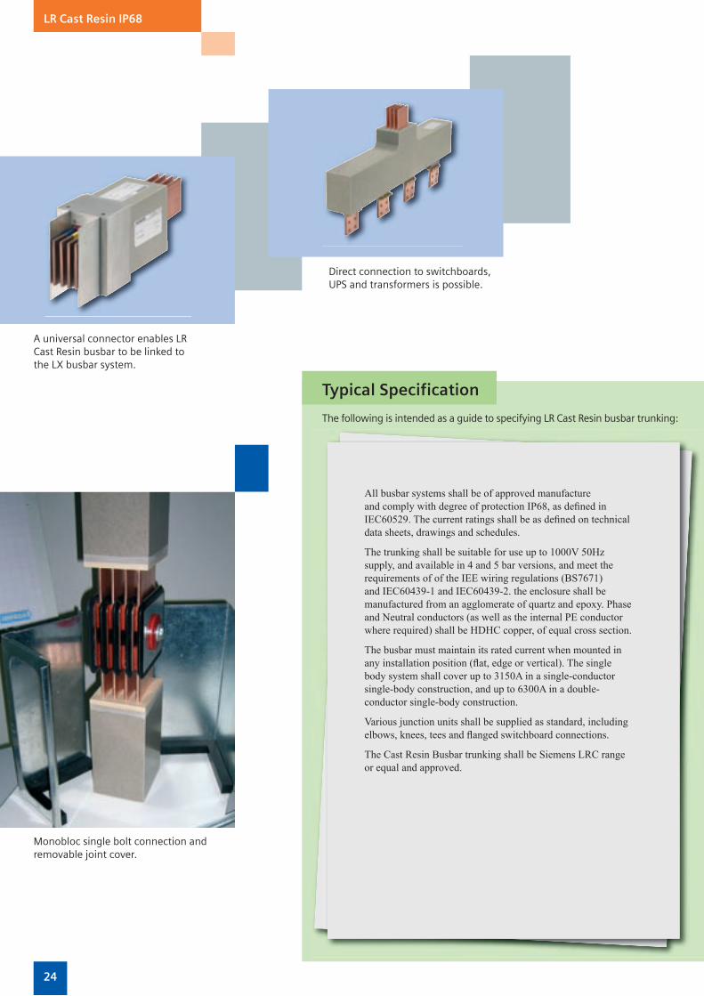
Direct connection of Siemens LR cast resin to LX metallic systems is possible using the connection element.
The epoxy cast resin system can be easily adapted to the building
Mechanical rigidity is achieved by insulating the conductors within the busbar trunking system using an agglomerate of quartz-epoxy. This is highly resistant to chemical agents and mechanical stress, offering IP68 degree of ingress protection (3.5 bar, 13.5 h) and high short-circuit resistance.
Flexible and effective
The compact construction allows the LR trunking to be positioned either fl at or on its edge, vertically
layout, by using angles, sets and tees to change direction or negotiate obstacles, and with the lowest space requirements.
Simple mono-bloc joints allow quick installation in the smallest spaces.
24 25
LR Cast Resin IP68
All busbar systems shall be of approved manufacture and comply with degree of protection IP68, as defi ned in IEC60529. The current ratings shall be as defi ned on technical data sheets, drawings and schedules.
The trunking shall be suitable for use up to 1000V 50Hz supply, and available in 4 and 5 bar versions, and meet the requirements of of the IEE wiring regulations (BS7671) and IEC60439-1 and IEC60439-2. the enclosure shall be manufactured from an agglomerate of quartz and epoxy. Phase and Neutral conductors (as well as the internal PE conductor where required) shall be HDHC copper, of equal cross section.
The busbar must maintain its rated current when mounted in any installation position (fl at, edge or vertical). The single body system shall cover up to 3150A in a single-conductor single-body construction, and up to 6300A in a double- conductor single-body construction.
Various junction units shall be supplied as standard, including elbows, knees, tees and fl anged switchboard connections.
The Cast Resin Busbar trunking shall be Siemens LRC range or equal and approved.
Typical Specification
The following is intended as a guide to specifying LR Cast Resin busbar trunking:
A universal connector enables LR Cast Resin busbar to be linked to the LX busbar system.
Direct connection to switchboards, UPS and transformers is possible.
Monobloc single bolt connection and removable joint cover.
24 25
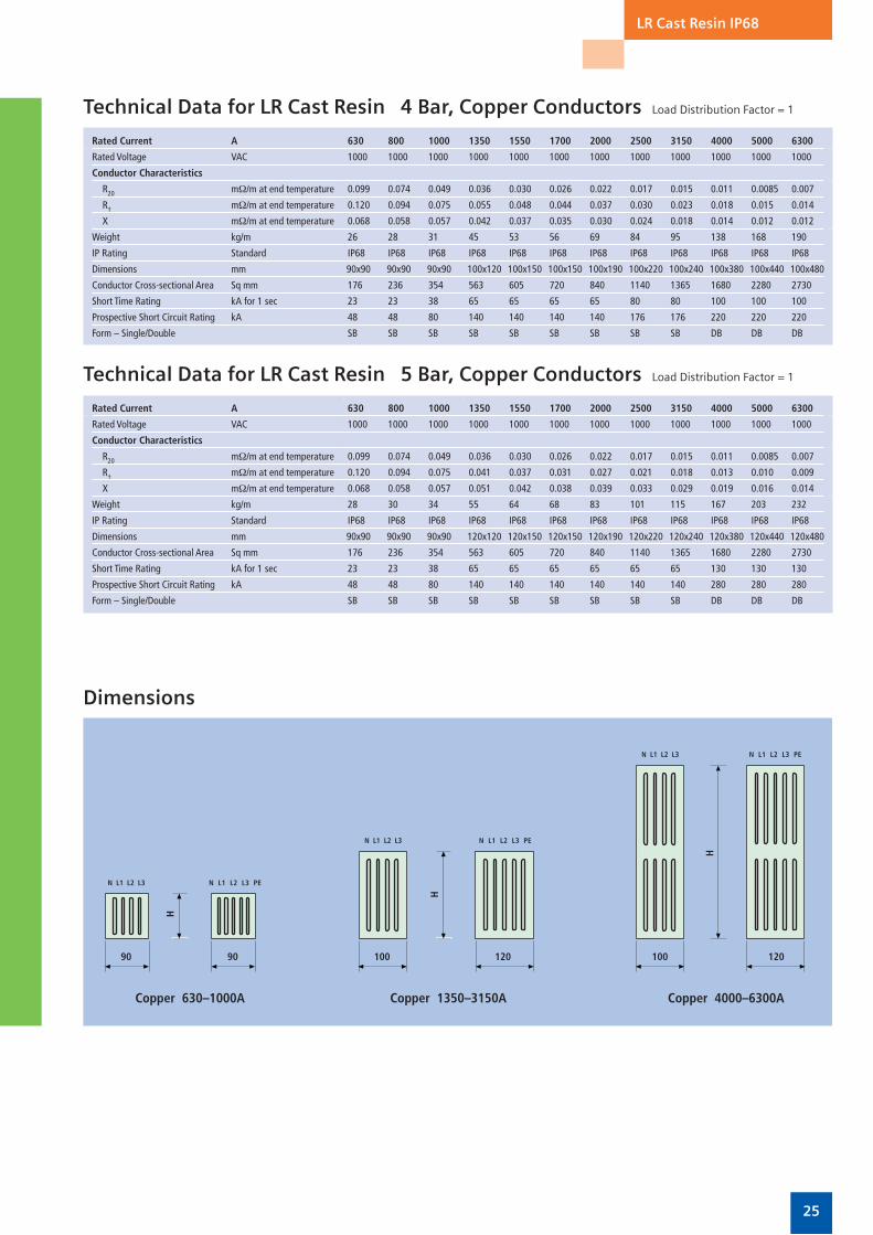
Technical Data for LR Cast Resin 4 Bar, Copper Conductors Load Distribution Factor = 1
Rated Current A 630 800 1000 1350 1550 1700 2000 2500 3150 4000 5000 6300
Rated Voltage VAC 1000 1000 1000 1000 1000 1000 1000 1000 1000 1000 1000 1000
Conductor Characteristics
R20 mΩ/m at end temperature 0.099 0.074 0.049 0.036 0.030 0.026 0.022 0.017 0.015 0.011 0.0085 0.007
R† mΩ/m at end temperature 0.120 0.094 0.075 0.055 0.048 0.044 0.037 0.030 0.023 0.018 0.015 0.014
X mΩ/m at end temperature 0.068 0.058 0.057 0.042 0.037 0.035 0.030 0.024 0.018 0.014 0.012 0.012
Weight kg/m 26 28 31 45 53 56 69 84 95 138 168 190
IP Rating Standard IP68 IP68 IP68 IP68 IP68 IP68 IP68 IP68 IP68 IP68 IP68 IP68
Dimensions mm 90x90 90x90 90x90 100x120 100x150 100x150 100x190 100x220 100x240 100x380 100x440 100x480
Conductor Cross-sectional Area Sq mm 176 236 354 563 605 720 840 1140 1365 1680 2280 2730
Short Time Rating kA for 1 sec 23 23 38 65 65 65 65 80 80 100 100 100
Prospective Short Circuit Rating kA 48 48 80 140 140 140 140 176 176 220 220 220
Form – Single/Double SB SB SB SB SB SB SB SB SB DB DB DB
Technical Data for LR Cast Resin 5 Bar, Copper Conductors Load Distribution Factor = 1
Rated Current A 630 800 1000 1350 1550 1700 2000 2500 3150 4000 5000 6300
Rated Voltage VAC 1000 1000 1000 1000 1000 1000 1000 1000 1000 1000 1000 1000
Conductor Characteristics
R20 mΩ/m at end temperature 0.099 0.074 0.049 0.036 0.030 0.026 0.022 0.017 0.015 0.011 0.0085 0.007
R† mΩ/m at end temperature 0.120 0.094 0.075 0.041 0.037 0.031 0.027 0.021 0.018 0.013 0.010 0.009
X mΩ/m at end temperature 0.068 0.058 0.057 0.051 0.042 0.038 0.039 0.033 0.029 0.019 0.016 0.014
Weight kg/m 28 30 34 55 64 68 83 101 115 167 203 232
IP Rating Standard IP68 IP68 IP68 IP68 IP68 IP68 IP68 IP68 IP68 IP68 IP68 IP68
Dimensions mm 90x90 90x90 90x90 120x120 120x150 120x150 120x190 120x220 120x240 120x380 120x440 120x480
Conductor Cross-sectional Area Sq mm 176 236 354 563 605 720 840 1140 1365 1680 2280 2730
Short Time Rating kA for 1 sec 23 23 38 65 65 65 65 65 65 130 130 130
Prospective Short Circuit Rating kA 48 48 80 140 140 140 140 140 140 280 280 280
Form – Single/Double SB SB SB SB SB SB SB SB SB DB DB DB
LR Cast Resin IP68
Copper 4000–6300A
Dimensions
Copper 630–1000A
100
N L1 L2 L3
N L1 L2 L3
N L1 L2 L3 PE
N L1 L2 L3 PE
120 100 120
H
H
90
N L1 L2 L3 N L1 L2 L3 PE
90
H
Copper 1350–3150A

26 27
Networked Busbar Trunking Systemscombining economy and flexibility
Networked Busbar
Volvo Cars, Belgium – redundant and fl exible power distribution solution for Europe’s most modern welding lines.
Automation combined with power distribution for fl exible use in international DIY stores.
The rising demand for dynamic data for building and industrial automation, as well as the increasing requirement for diagnostic information has driven the need for intelligent networking of installed applications.
The logical next step
The networking of applications in the tap-off units of Siemens’ busbar trunking is the logical development for busbar trunking systems. Based on standard types of tap-off units combined with an additional ancillary equipment unit, the network is formed by laying a bus cable in a special cable duct on the busbar trunking and connecting components to this bus. Open multi-vendor bus systems (including EIB, AS-i and LON) with a high level of interoperability form
Tap-off/ancillary equipment with combination networked on a BD2 system using AS-Interface, such as for remote monitoring and switching of switch-disconnectors.
the substructure of networkable tap-off/ancillary equipment unit combinations.
The networking components
The use of networkable components with the BD01, BD2, LD and LX systems, and a well designed accessory package with a special bus duct enables the networking of all current ranges, and also allows existing installations to be upgraded.
The details of the power used can be measured by transducers at the feeder in the tap-off unit and made available on the data bus via a bus-compatible evaluation module in the device unit. This application is available both for LON and AS-Interface bus systems.
Standard functions Function expansion Bus connection
Standard tap-offunits
Lighting control for extensive lighting systems
Switching/signallingRemote operation/remotemonitoring
Consumption measurementCentral data acquisition of decentralized power consumers
26 27
Temperature Monitoring
Busbar Temperature Monitoring
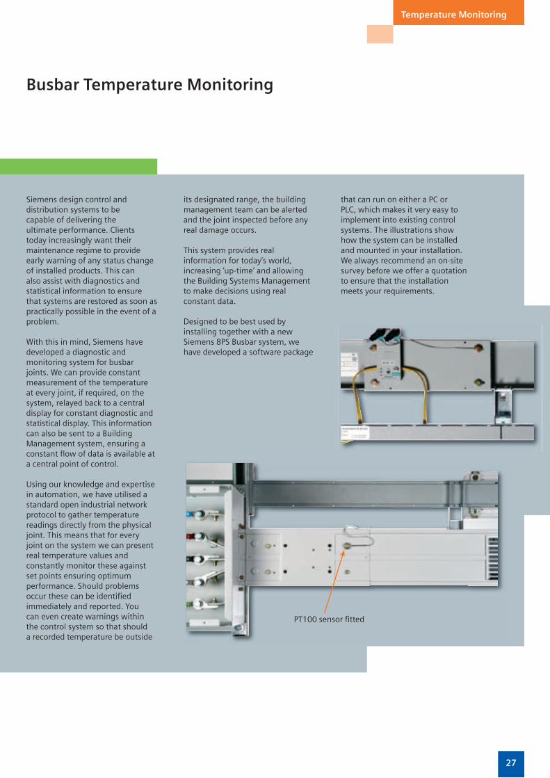
Siemens design control and distribution systems to be capable of delivering the ultimate performance. Clients today increasingly want their maintenance regime to provide early warning of any status change of installed products. This can also assist with diagnostics and statistical information to ensure that systems are restored as soon as practically possible in the event of a problem.
With this in mind, Siemens have developed a diagnostic and monitoring system for busbar joints. We can provide constant measurement of the temperature at every joint, if required, on the system, relayed back to a central display for constant diagnostic and statistical display. This information can also be sent to a Building Management system, ensuring a constant fl ow of data is available at a central point of control.
Using our knowledge and expertise in automation, we have utilised a standard open industrial network protocol to gather temperature readings directly from the physical joint. This means that for every joint on the system we can present real temperature values and constantly monitor these against set points ensuring optimum performance. Should problems occur these can be identifi ed immediately and reported. You can even create warnings within the control system so that should a recorded temperature be outside
its designated range, the building management team can be alerted and the joint inspected before any real damage occurs.
This system provides real information for today’s world, increasing ‘up-time’ and allowing the Building Systems Management to make decisions using real constant data.
Designed to be best used by installing together with a new Siemens 8PS Busbar system, we have developed a software package
PT100 sensor fi tted
that can run on either a PC or PLC, which makes it very easy to implement into existing control systems. The illustrations show how the system can be installed and mounted in your installation. We always recommend an on-site survey before we offer a quotation to ensure that the installation meets your requirements.

Siemens A&D UK
Sir William Siemens HousePrincess RoadManchester M20 2UR
Tel: 0161 446 6400Fax: 0161 446 5403
www.automation.siemens.co.uk
The information provided in this brochure contains merely general descriptions or characteristics of perform-ance which in case of actual use do not always apply as described or which may change as a result of further development of the products. An obligation to provide the respective characteristics shall only exist if expressly agreed in the terms of contract.
B U S B A R S Y S T E M S
25 to 6300 Amps
July 2006
CD/BD01/BD2 CatalogueLV70 – 2004
LX CatalogueLV72T – 2004
LR CatalogueTBA
Mohelnicebusbarfactory