SIDEWINDER OWNER’S MANUAL PAGE ... - Aztec … · SIDEWINDER OWNER’S MANUAL PAGE 5 04-2017...
35
SIDEWINDER OWNER’S MANUAL PAGE 1 04-2017 OWNER’S MANUAL SIDEWINDER 24” & 30” Propane WorkSmart ® Stripping Machine WWW.AZTECPRODUCTS.COM 800-331-1423 * 201 COMMERCE DRIVE, MONTGOMERYVILLE, PA 18936
Transcript of SIDEWINDER OWNER’S MANUAL PAGE ... - Aztec … · SIDEWINDER OWNER’S MANUAL PAGE 5 04-2017...

SIDEWINDER OWNER’S MANUAL PAGE 1
04-2017
OWNER’S MANUAL SIDEWINDER 24” & 30”
Propane WorkSmart® Stripping Machine
WWW.AZTECPRODUCTS.COM 800-331-1423 * 201 COMMERCE DRIVE, MONTGOMERYVILLE, PA 18936
SIDEWINDER OWNER’S MANUAL PAGE 2
04-2017
TABLE OF CONTENTS
TABLE OF CONTENTS PG 2
INTRODUCTION PG 3
SAFETY MESSAGE INFORMATION PG 3
IMPORTANT SAFETY INSTRUCTIONS PG 4
GUIDE TO GRAPHICAL SYMBOLS & PRODUCT LABELS PG 4
GENERAL OPERATION SAFETY INFORMATION PG 5-7
STORAGE AND HANDLING SAFETY INFORMATION PG 8
RETAILER/DISTRIBUTOR CONTACT INFO PG 8
MAINTENANCE SAFETY INFORMATION PG 9
SIDEWINDER OPERATION PG 10-11
BEFORE OPERATION CHECKLIST PG 12-13
SIDEWINDER – GETTING STARTED PG 13-14
STOPPING THE ENGINE PG 14
TRANSPORTING THE MACHINE PG 14
MACHINE CLEAN-UP PG 15
ENGINE MAINTENANCE METER PG 15
TROUBLESHOOTING – ELEC SYSTEM & MAIN DRIVE PG 16-17
NOTES PG 18
STORING THE MACHINE & PROPANE TANKS PG 18
ENGINE OIL & MAINTENANCE PG 19-20
ENGINE MAINTENANCE SCHEDULE PG 21
TOUBLESHOOTING – ENGINE PG 21
BATTERY START WIRING DIAGRAM PG 22
ENGINE TUNE UP SPECS PG 22
SIDEWINDER QUICK START DIAGRAM PG 23
SIDEWINDER WARNING LABEL LOCATIONS PG 24
SIDEWINDER 30” BODY PARTS PG 25
SIDEWINDER 30” UPPER DRIVE PARTS PG 26
SIDEWINDER 30” LOWER DRIVE PARTS PG 27
SIDEWINDER 24” BODY PARTS PG 28
SIDEWINDER 24” UPPER DRIVE PARTS PG 29
SIDEWINDER 24” LOWER DRIVE PARTS PG 30
SIDEWINDER BRUSH OPTIONS PG 31
SIDEWINDER PAD DRIVER SYSTEM PG 31
SIDEWINDER PAD ASSEMBLY PG 31
FUEL SYSTEM 12V STARTER PARTS LIST PG 32
PUREPOWER 603cc ENGINE PARTS PG 33
WARRANTY PG 34
SIDEWINDER OWNER’S MANUAL PAGE 3
04-2017
INTRODUCTION
Thank you for purchasing this Aztec Products, Inc. machine. You have purchased a quality product and
we welcome you to the Aztec family. It is critically important to utilize proper training, understanding,
maintenance and care for this product. Neglect of the Safety Messages, especially the DANGER,
WARNING, CAUTION and NOTICE statements throughout this Owner’s Manual may lead to serious
injury or death, and/or cause damage to the floor and/or facility.
For best results from your Aztec machine, you must read and understand this Owner’s Manual, and
follow all operation guidelines and safety messages. Protect your WARRANTY by following all
maintenance guidelines and keeping a dated log. If a problem should arise, consult an authorized Aztec
service center.
All information in this Owner’s Manual is up to date and based on the latest product information
available at the time. Aztec Products, Inc. reserves the right to make changes at any time without notice
or incurring obligation. This Owner’s Manual and the maintenance log must be kept as a permanent
part of the machine and remain with the machine if resold.
No part of this document may be copied or reproduced without written permission.
SAFETY MESSAGE INFORMATION
Your safety and the safety of others is very important. As the manufacturer, we have provided
important safety messages throughout this manual and on the machine. The purpose of these safety
messages is to prevent damage to you, your machine, the property, and/or the environment.
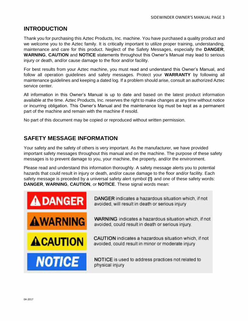
Please read and understand this information thoroughly. A safety message alerts you to potential
hazards that could result in injury or death, and/or cause damage to the floor and/or facility. Each
safety message is preceded by a universal safety alert symbol (!) and one of these safety words:
DANGER, WARNING, CAUTION, or NOTICE. These signal words mean:

SIDEWINDER OWNER’S MANUAL PAGE 4
04-2017
IMPORTANT SAFETY INSTRUCTIONS
READ and UNDERSTAND all instructions and safety messages before operating this machine.
Follow the instructions given in this Owner’s Manual and the training given by your supervisor for the
safe operation of this machine. Failure to do so can result in personal injury and/or damage to the
machine or property.
GUIDE TO GRAPHICAL SYMBOLS AND PRODUCT LABELS
DANGER, WARNING OR CAUTION; read all instructions before using
Hot surface – Do not touch
Wear hearing protection when operating
Wear safety goggles when operating
Switch “On” Position
Switch “Off” position
SIDEWINDER OWNER’S MANUAL PAGE 5
04-2017
GENERAL OPERATION SAFETY INFORMATION
Liquefied petroleum gas (LPG or propane) is stored under pressure and must be handled in the proper
manner to be safe. Observe the following safety messages to get the best performance, lowest
emissions, and longest life out of your equipment.
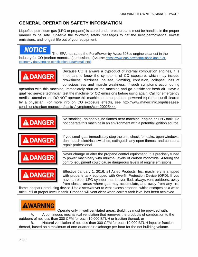
The EPA has rated the PurePower by Aztec 603cc engine cleanest in the industry for CO (carbon monoxide) emissions. (Source: https://www.epa.gov/compliance-and-fuel-
economy-data/engine-certification-data#small-nrsi).
Because CO is always a byproduct of internal combustion engines, it is
important to know the symptoms of CO exposure, which may include
drowsiness, dizziness, nausea, vomiting, confusion, collapse, loss of
consciousness and muscle weakness. If such symptoms occur during
operation with this machine, immediately shut off the machine and go outside for fresh air. Have a
qualified service technician test the machine for CO emissions before using again. Call for emergency
medical attention and DO NOT operate this machine or other propane powered equipment until cleared
by a physician. For more info on CO exposure effects, see http://www.mayoclinic.org/diseases-
conditions/carbon-monoxide/basics/symptoms/con-20025444.
No smoking, no sparks, no flames near machine, engine or LPG tank. Do not operate this machine in an environment with a potential ignition source.
If you smell gas: immediately stop the unit, check for leaks, open windows, don’t touch electrical switches, extinguish any open flames, and contact a repair professional.
Never change or alter the propane control equipment. It is precisely tuned to power machinery with minimal levels of carbon monoxide. Altering the control equipment could cause dangerous levels of engine emissions.
Effective January 1, 2016, all Aztec Products, Inc. machinery is shipped with propane tank equipped with Overfill Protection Device (OPD). If you have an older LPG cylinder that is overfilled, always vent outdoors, away from closed areas where gas may accumulate, and away from any fire,
flame, or spark-producing device. Use a screwdriver to vent excess propane, which escapes as a white mist until at proper level in tank. Propane will vent clear when correct tank level has been achieved.
Operate only in well ventilated areas. Buildings must be provided with: A. A continuous mechanical ventilation that removes the products of combustion to the
outdoors of not less than 300 CFM for each 10,000 BTUH or fraction thereof; or B. Natural ventilation of not less than 300 CFM for each 10,000 BTUH input or fraction
thereof, based on a maximum of one-quarter air exchange per hour for the net building volume.

SIDEWINDER OWNER’S MANUAL PAGE 6
04-2017
Keep hands and feet clear of moving parts to avoid injury.
Although this PurePower engine is equipped with a catalytic muffler for safety, its exhaust may still contain trace amounts of poisonous CO (carbon monoxide) gas and/or chemicals known in the state of California to cause cancer, birth defects or other reproductive harm. Do not run the engine without adequate ventilation.
HOT MUFFLER CAN BURN YOU. Stay away if engine has been running.
Never let an untrained or irresponsible person operate the machine. They may hurt themselves and/or damage the floor or other property.
Always check oil before attempting to start engine. Low oil may result in serious and expensive engine damage.
Never complete the connection of the propane tank to the machine by using a tool; always tighten and loosen by hand. Use of tools to tighten or loosen tank connection may result in damage to tank valve and insecure connection. Listen for the rush of fuel to the lock-out device when you open the tank valve. If you hear this, it will indicate that a good connection has been made at the tank.
Muffler is HOT. Keep all heat sensitive objects away from the exhaust system during and after operation. Damage can occur to the machine, furniture, buildings and/or personal injury.
Do not leave this machine unattended while the engine is running. Damage to floor surface or other property may occur and fumes may accumulate.
Do not operate machine in a stationery spot for more than a few seconds. Machine is designed to be moved continuously forward at a measured pace. Stationary operation will result in damage to floor surface.
SIDEWINDER OWNER’S MANUAL PAGE 7
04-2017
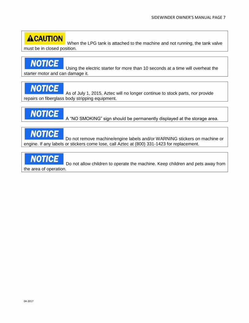
When the LPG tank is attached to the machine and not running, the tank valve must be in closed position.
Using the electric starter for more than 10 seconds at a time will overheat the starter motor and can damage it.
As of July 1, 2015, Aztec will no longer continue to stock parts, nor provide repairs on fiberglass body stripping equipment.
A “NO SMOKING” sign should be permanently displayed at the storage area.
Do not remove machine/engine labels and/or WARNING stickers on machine or engine. If any labels or stickers come lose, call Aztec at (800) 331-1423 for replacement.
Do not allow children to operate the machine. Keep children and pets away from the area of operation.

SIDEWINDER OWNER’S MANUAL PAGE 8
04-2017
STORAGE AND HANDLING SAFETY INFORMATION
Always store equipment away from heater rooms, boilers, gas-fired water
heaters or any other source of open flame or ignition. The exhaust system
will be very hot and takes several minutes to cool, so keep yourself and all
materials clear.
Always store equipment away from possible damage by falling objects in warehouse-type areas.
Always store LPG tanks outside. Remove all propane tanks from inside building except during equipment use. Store them in a secure, well ventilated area.
If the engine has been running, allow it to cool for at least 15 minutes before loading the engine-powered equipment onto the transport vehicle. A hot engine and exhaust system can burn you and can ignite some materials.
This propane machine is intended for commercial use.
A “NO SMOKING” sign should be permanently displayed at the storage area.
Safety is a full-time, every day job. Follow all information posted on the machine and the LPG tank. Never allow anyone untrained to operate this machine, and who has not read or cannot understand the given instructions.
RETAILER/DISTRIBUTOR CONTACT INFO
PURCHASE DATE: DISTRIBUTOR NAME: DISTRIBUTOR PHONE NUMBER(S):
PROTECT YOUR WARRANTY! Read carefully; all questions regarding the care and safety of this equipment,
please call AZTEC PRODUCTS: (800) 331-1423

SIDEWINDER OWNER’S MANUAL PAGE 9
04-2017
MAINTENANCE SAFETY INFORMATION
Machine should only be tipped back for service if properly turned OFF, in a safe environment and positioned on a flat surface. Do not tilt machine on its side; damage can occur to the machine, furniture, buildings and/or personal injury.
Before attempting any service or maintenance, the engine switch must be in the OFF position and the propane tank valve must be in CLOSED position.
Because of the weight of this machine, a second person should assist the tilting back of the machine before any work is done on the underside of the machine.
Do not use the “T” handle as a lever when attempting to tilt back machine for service or cleaning. The “T” handle is designed for control during operation only. To tilt back machine, place one foot on the propane tank base bar, one hand on the handle base, and one hand on the “T” handle. Pull back and down from the handle base, and push down with your foot, using the “T” handle only to control lateral motion.
The manufacturer’s warranty will be voided if the machine is not maintained in accordance with this manual’s recommended maintenance instructions and the engine manufacturer’s recommended maintenance procedures. Failure to do so may cause damage to the machine, equipment, furniture, buildings and/or personal injury.
An abbreviated, quick reference schedule of the manufacturer’s suggested maintenance is on the underside of the handle. This abbreviated schedule is for quick reference only and is not intended to replace the full maintenance schedule in the Owner’s Manual.
A maintenance record must be kept, indicating all dates of service, hours on engine at time of service, and service performed in order to maintain manufacturer’s warranty coverage. Perfect record keeping does not guarantee warranty coverage if the damage to the machine is non-warrantable. See warranty coverage policy details at the end of this Owner’s Manual. The maintenance record must be kept with the machine and transferred to the new owner if resold.

SIDEWINDER OWNER’S MANUAL PAGE 10
04-2017
BEFORE OPERATION CHECKLIST
For your safety, to ensure compliance with environmental regulations, and to maximize the service life
of your equipment, it is very important to take a few minutes before you operate this machine to check
its condition. Be sure to take care of any problem you find, or have your service dealer correct it before
you operate this machine.
Improperly maintaining this machine and its engine, or failure to correct a problem before operation, may cause a malfunction and elevated emission levels. Always perform a pre-operation inspection before each use, and correct any problem.
Before beginning your Before Operation Checklist, the machine and engine must be on a level surface,
with the engine switch in the OFF position, and the propane tank valve is in the CLOSED position.
Always check the following items before you start the engine:
A. READ AND UNDERSTAND ALL SAFETY MESSAGES Carefully read and understand the SAFETY INSTRUCTIONS on pages 3-8.
B. CHECK THE GENERAL CONDITION OF THE MACHINE:
1.) Look around and underneath the machine and engine for signs of oil leaks. 2.) Remove any excessive dirt or debris, especially around the muffler and recoil starter. 3.) Look for signs of damage. 4.) Check that all shields and covers are in place, and all nuts, bolts and screws are tightened. 5.) Address all of the above issues before proceeding.
C. CHECK THE ENGINE: 1.) Check the engine oil level and filters. Running the engine with a low oil level can cause
engine damage. Your first oil change should be after the first 8 hours of use. 2.) Check the air filter element. A dirty air filter element will restrict air flow to the carburetor,
reducing engine performance and potentially increasing harmful engine emissions.
D. CHECK THE MAINTENANCE SCHEDULE All machines are equipped with a multi-function maintenance meter. The functions include the
following: hour meter, service alert and tachometer. (See ENGINE MAINTENANCE METER
instructions on pg 15).
E. CHECK THE ENGINE OIL
Make sure the machine is level when checking the oil. Always take two (2) readings of the
dipstick before adding oil. If the oil level is below the full mark, add just enough oil to the engine
to bring the oil level up to the full mark. Never over fill. Check for foreign material on the dipstick.
SIDEWINDER OWNER’S MANUAL PAGE 11
04-2017
F. CHECK THE PROPANE/LPG TANK AND LINES: 1.) Every tank has been pressure and leak tested. However, every time a tank is filled and/or
connected to the machine it should be soap tested. All LPG lines must be pressurized and every inch of line and connections must be sprayed. If you find a leak, make the proper repairs before operating the machine.
2.) Never overfill the LPG tank. The LPG tank is designed to hold a maximum of 20 pounds of propane. Make sure to weigh the tank as it is being filled. The gross weight of a full tank should not exceed 48 pounds. If, while operating the machine, you notice frost forming on the LPG lines or the regulator, your tank has been over filled. If you continue to operate the machine in this condition, damage will occur. The excess propane in the tank must be removed before normal operations resume. The bleeding of a propane tank must be done in a safe manner; refer to the GENERAL OPERATION SAFETY INFORMATION on pages 3-8. In some cases, the regulator must defrost before restarting the engine.
3.) To connect the high pressure hose to the LPG tank, make sure the couplers are in line and screwed together, hand tight. If this is not done properly, fuel will not pass through to the regulator. Never complete the connection of the tanks to the machine by using a tool.

SIDEWINDER OWNER’S MANUAL PAGE 12
04-2017
SIDEWINDER OPERATION
This ultra-high speed VCT (vinyl composite tile) stripping and scrubbing machine is designed for
superior performance and long term durability. It includes a heavy-duty German engineered, precision
centrifugal clutch that will substantially increase the belt life. No application, other than ultra-high speed
VCT stripping and scrubbing, should be attempted nor is recommended. Call Aztec (800) 331-1423 for
any additional application questions.
First, refer to the SAFETY INFORMATION on pages 3-8, and complete the BEFORE OPERATION
CHECKLIST on page 12-13.
Never tilt back machine while engine is running. Objects may fly out from underside of machine and damage can occur to the machine, furniture, buildings and/or personal injury.
The engine and exhaust become very hot during operation. Keep the engine at least 1 meter (3 feet) away from buildings and other equipment. Keep flammable materials away, and do not place anything on the engine while it is running.
Factory engine speed is set at approximately 3400 RPM. Tampering with the settings will void the warranty and injury can result. Refer to the equipment specifications.
Continuous exposure to high noise levels can cause hearing loss. Although not required by OSHA based on engine volume, hearing protection is recommended while the machine is in operation. In compliance with OSHA regulations, the operational weighted sound level of this machine is less than 89dB(A).
Prolonged exposure to machine vibration may cause tingling or numbness in the fingers and hands. Use of gloves and limits to operator vibration exposure are recommended to prevent such symptoms. The operational hand/arm vibration level of this machine is less than 2.5m/s2.
Per OSHA standards, ear protection is not required, but is suggested during operation.
All machines are equipped with tamper proof fuel systems. If a fuel problem exists, contact an authorized service center.
SIDEWINDER OWNER’S MANUAL PAGE 13
04-2017
All machines are equipped with a multi-function maintenance meter. The functions include the following: hours, service alert and tachometer; see ENGINE MAINTENANCE METER instructions on page 15.
Do not use this machine on surfaces with a gradient exceeding 2%.
This machine is supplied with a centrifugal clutch. When the engine RPM is lower than 1800 RPM, the clutch will disengage; brush/pad will stop.
Make sure the operator receives adequate instruction before operating the equipment.

SIDEWINDER OWNER’S MANUAL PAGE 14
04-2017
SIDEWINDER – GETTING STARTED
Strip brushes and pad drivers are LEFT hand threaded. Turn clockwise to loosen, and counter-clockwise to tighten. Turning bolts in the wrong direction will shear the bolt head and damage the machine.
Do not remove tape from strip brushes. Removing the tape from the strip brush reduces the brush life and effectiveness.
Responsibly dispose of used pads and brushes.
Never “flip” a pad. Keep the same side down throughout the life of the pad. Even after a pad is cleaned, you can tell the down side by the centering ring indentation. This practice will increase the pad life and help maintain a properly functioning pad driver.
1.) Refer to OPERATION on pgs 10-11 and complete the BEFORE OPERATION CHECKLIST on
pages 12-13.
2.) To install scrub pads or strip brushes, tilt machine back and secure in place. To tilt back the machine safely, refer to TRANSPORTING THE MACHINE on page 14.
3.) Once the machine is securely tipped back in position, remove the pads. Remove and responsibly dispose of the old pads. Be sure to center the new pad in the center of the pad holders. For brushes, turn clockwise to remove, and counter clockwise to install new brushes.
4.) Return machine back to level position before proceeding.
5.) Adjust the machine handle to comfortable position using pin provided to secure in place.
6.) Open the LPG tank valve by turning counter clockwise.
7.) Set the throttle control switch to the SLOW position.
8.) Turn the key switch to the “START” position until engine starts. Starter should not be engaged for more than 10 seconds at a time. Using the electric starter for more than 10 seconds at a time will overheat the starter motor and can damage it. If hard starting is a problem, carefully review BEFORE OPERATION CHECKLIST pages 12-13. As soon as the engine starts, move throttle cable into desired engine speed.
9.) When the job is complete, the Sidewinder must be cleaned. See MACHINE CLEAN UP steps on page 15.

SIDEWINDER OWNER’S MANUAL PAGE 15
04-2017
STOPPING THE ENGINE
Turn the propane tank valve clockwise to CLOSED position and turn the engine key to OFF position. Refer to TRANSPORTING THE MACHINE on pg 14, and MACHINE CLEAN-UP and STORING THE MACHINE & PROPANE TANKS on pg 18.
TRANSPORTING THE MACHINE
The Sidewinder must be secured on a level surface when transporting in a vehicle. Once the machine is loaded into the transport vehicle, remove and store the transport wheel on the top deck of the machine. Secure the machine in the vehicle so it cannot move or bounce during transporting; damage may occur to the machine and/or the vehicle and surrounding objects.
First, refer to the SAFETY INFORMATION on pages 3-8. Refer to MACHINE CLEAN UP on pg 15. The machine must be on a level surface, with the engine switch in the OFF position, and the propane tank valve in the CLOSED position. Remove the propane tank from the machine, or disconnect the connection and securely fasten tank to machine. Adjust handle of machine to comfortable position to tilt back. To tilt back the machine, place one foot on the propane tank base bar, one hand on the handle base, and one hand on the “T” handle. Pull back and down from the handle base, and push down with your foot, using the “T” handle only to control lateral motion. Once secured in a tilted back position, insert transport wheel and secure with pin provided. Push machine forward, to desired location, unless loading machine up on a ramp into a vehicle. When loading up a ramp into a vehicle, the machine should be pulled back rather than pushed forward, to prevent tipping over. Return and secure transport wheel to storage slot on top deck of the machine when not in use, and when the machine is being transported in a vehicle.
MACHINE CLEAN UP
Refer to the SAFETY INFORMATION on pages 3-8. Once the job is complete for the day/night, clean
up is required. The manufacturer’s and engine warranty will be voided if the equipment is not properly
maintained. Clean the entire machine after each use:
A. Turn the propane tank valve clockwise to CLOSED position and turn the engine key to OFF position.
B. Refer to TRANSPORTING THE MACHINE on page 14 to properly tilt back and secure
machine.
C. Check the machine for possible loose nuts and bolts; tighten and secure as needed.
D. Rinse around splash skirt and body of machine. Rinse the underside of the machine, including the underside and top side of the main drive unit. Do not spray water inside main drive unit through the brush bolt openings. The outside of the drum should be completely free of any contaminants.

SIDEWINDER OWNER’S MANUAL PAGE 16
04-2017
E. All air and oil filters should be cleaned.
F. Return the machine to leveled operating position, then start engine and run machine for 2-3 minutes to expel any excess water.
When cleaning the machine, avoid getting water around the engine and battery. Water may cause damage to the engine and/or battery unit.
ENGINE MAINTENANCE METER
This multi-function meter acts as a preventive maintenance tool, which benefits you with increased fuel
economy, less down-time and longer engine life.
The meter displays are:
• Hour Meter: Displays total run hours when machine is off.
• Tachometer: Indicates engine RPM during operation.
• Service Alert: The display flashes to alert you to lube and change the oil at 25 hour intervals. After the service is complete, the meter can be reset by pushing the reset button on the face of the meter. Therefore, it is recommended that a separate maintenance log be kept to track of oil changes.

SIDEWINDER OWNER’S MANUAL PAGE 17
04-2017
TROUBLESHOOTING - ELECTRICAL SYSTEM
Always wear a face shield, safety glasses and protective clothing when working around a battery. The gases can be explosive and the acid is highly corrosive to metals, cloth and ALL HUMAN TISSUE (skin, eyes, etc.).
Safety first. Contact an authorized service center as needed.
• Check all wire connections for obvious problems. Remove propane tank, then remove battery box cover. Check all connections visibly and physically. If any “loose”, damaged or unconnected wires are noticed, replace or repair as needed.
• Check the battery posts and wires. If the battery post(s) are corroded, remove the wires and clean posts and wires. Applying some axle grease on the posts of the battery after they are cleaned will slow down the battery corrosion process. If nothing obvious is noted, a more detailed investigation is warranted. Before any such troubleshooting begins, the following things should be done:
o Replace propane tank with one from a machine that runs. o Charge the battery or provide an absolute source of 12-volt DC power capable of 50
amperes total output. Jumper cables from a car or truck battery will suffice. Use a 12-volt test light.
• If the problem appears to be in the electrical control equipment, disconnect the starter from the system so as to check the system without spinning the engine.
• Battery rundown is a common problem. An engine key left in the ON position when engine is turned OFF will result in battery running down.
SIDEWINDER OWNER’S MANUAL PAGE 18
04-2017
TROUBLESHOOTING - MAIN DRIVE BELT
Safety first. Contact an authorized service center as needed. Refer to the
SAFETY INFORMATION on pages 3-8.
If the engine runs but the drive unit will not engage, this is usually related to the Engine Drive Belt or
the Belt Tension Spring. Without removing the drive unit you can check and fix the following:
1) Remove the four (4) 3/8" bolts holding the belt cover to the body. Remove the 3/8" bolt holding the Muffler Bracket to the Belt Cover. Check if the Belt Tension Spring is attached to the bolt located on the Idler Spring Plate on the body. Refer to the Upper Drive diagram on page 26 (for the 30” Sidewinder) or page 29 (for the 24” Sidewinder).
2) Check to see if the Engine Drive Belt has come off the Input Pulley or Centrifugal Clutch. If so, carefully raise front of machine off the floor to install the belt back onto the pulley. To safely tip back and secure the machine, refer to TRANSPORTING THE MACHINE on pg 14.
If the Engine Drive Belt comes off again it is probably worn or stretched and in need of replacement. To order a replacement, contact Aztec Customer Service: (800) 331-1423. Always dispose of old materials responsibly.
If further investigation is required, you will need to remove the drive unit:
3.) To replace the Engine Drive Belt, remove old or worn belt and replace them with the new ones.
a. Remove one end of the Belt Tension Spring to aid in installation of new belt. Check for wear on the springs and their catches.
4.) Slide the Belt Cover back into place and insert four (4) 3/8" bolts into belt cover (hand tighten
only). Insert the 3/8" bolt into Muffler Bracket and Belt Cover, then tighten all five (5) 3/8" bolts. To change the Brush Drive Belt:
5.) Refer to step one above.
6.) Remove three (3) bolts on the right side of upper deck (use a 3/4" wrench). Slowly raise front of machine off the floor. Refer to TRANSPORTING THE MACHINE on pg 14.
7.) Remove Input Boom Pulley and Head Support Boom Arm from above the Brush Drive by using the two ¾" wrenches—sliding one ¾” wrench below the pillow block bearing, and the other wrench in the slot above the Pillow Block Bearing; unscrew the two shafts apart.
8.) Remove the six (6) bolts from the bottom side of Brush Drive and split Brush Drive Top Pan and Brush Drive Plate.
9.) Remove worn belt and replace.
10.) It is a good idea at this time to check the Tension Spring (belt?), bearings and the idler for damage and replace them if necessary.
Once the brush belt drive has been replaced, reassemble following the above steps in reverse.
SIDEWINDER OWNER’S MANUAL PAGE 19
04-2017
NOTES
STORING THE MACHINE AND PROPANE TANKS
Once the job is complete for the day/night, remove the propane tank from the machine and store the tank in a well ventilated approved area. Store your machine in a safe and secure area. Refer to the SAFETY INFORMATION on pages 3-8. Also refer to TRANSPORTING THE MACHINE on pg 14, and MACHINE CLEAN-UP on pg 15.

SIDEWINDER OWNER’S MANUAL PAGE 20
04-2017
ENGINE OIL AND MAINTENANCE
Hot engine oil can cause severe burns. Allow engine temperature to drop from hot to warm level before attempting to remove oil filter.
Check the engine oil daily before starting the engine, otherwise shortage of the engine oil may cause serious damage to the engine such as seizure.
Engine oil is a toxic substance. Dispose of used oil properly. Contact local authorities for approved disposal methods or possible recycling.
Refer to the SAFETY INFORMATION on pages 3-8. Also refer to the BEFORE OPERATION
CHECKLIST on pages 12-13 before operating this machine. Then carefully follow these guidelines:
A.) RECOMMENDED OIL The following engine oils are recommended: API Service Classification: SF, SG, SH, or SJ.
B.) CHECK THE OIL 1) To check the oil, the engine should be turned OFF, and the machine should be on a level
surface. 2) Clean the area around the oil gauge before removing it. 3) Remove the oil gauge and wipe it with a clean cloth. 4) Pour the oil slowly to “FULL” mark on the oil gauge. 5) Insert the oil gauge into the tube WITHOUT SCREWING IT IN. 6) Remove the oil gauge to check the oil level. The oil level should be between “ADD” and
“FULL” marks. Do not overfill. 7) Install and tighten the oil gauge.
C.) OIL VISCOSITY Choose the viscosity according to the temperature as follows:
Using multi-grade oils (5W-20, 10W-30, and 10W-40) will increase oil
consumption. Check oil level more frequently when using them.
SIDEWINDER OWNER’S MANUAL PAGE 21
04-2017
D.) ENGINE OIL CAPACITY:
FS381V 1.5 l (1.6 US qt) when oil filter is not removed FS500V 1.7 L (1.8 US qt.) when oil filter is removed FS541V 1.7 L (1.8 US qt) when oil filter is removed FS600V 1.7 L (1.8 US qt) when oil filter is removed
E.) OIL CHANGES Change oil after first 8 hours of operation. Thereafter change oil every 50 hours. Refer to the PUREPOWER ENGINE MAINTENANCE SCHEDULE on pg 21.
• Run the engine to warm oil.
• Be sure the engine (equipment) is level.
• Stop the engine.
• Open the oil drain valve and drain the oil into suitable container while engine is warm.
F.) OIL DRAIN PLUG
• Close the oil drain valve.
• Remove oil gauge and refill with fresh oil (See RECOMMENDED OIL on page 19).
• Check the oil level (refer to the BEFORE OPERATION CHECKLIST on pages 12-13 for OIL LEVEL CHECK). Also, refer to the PUREPOWER ENGINE MAINTENANCE SCHEDULE on pg 21.
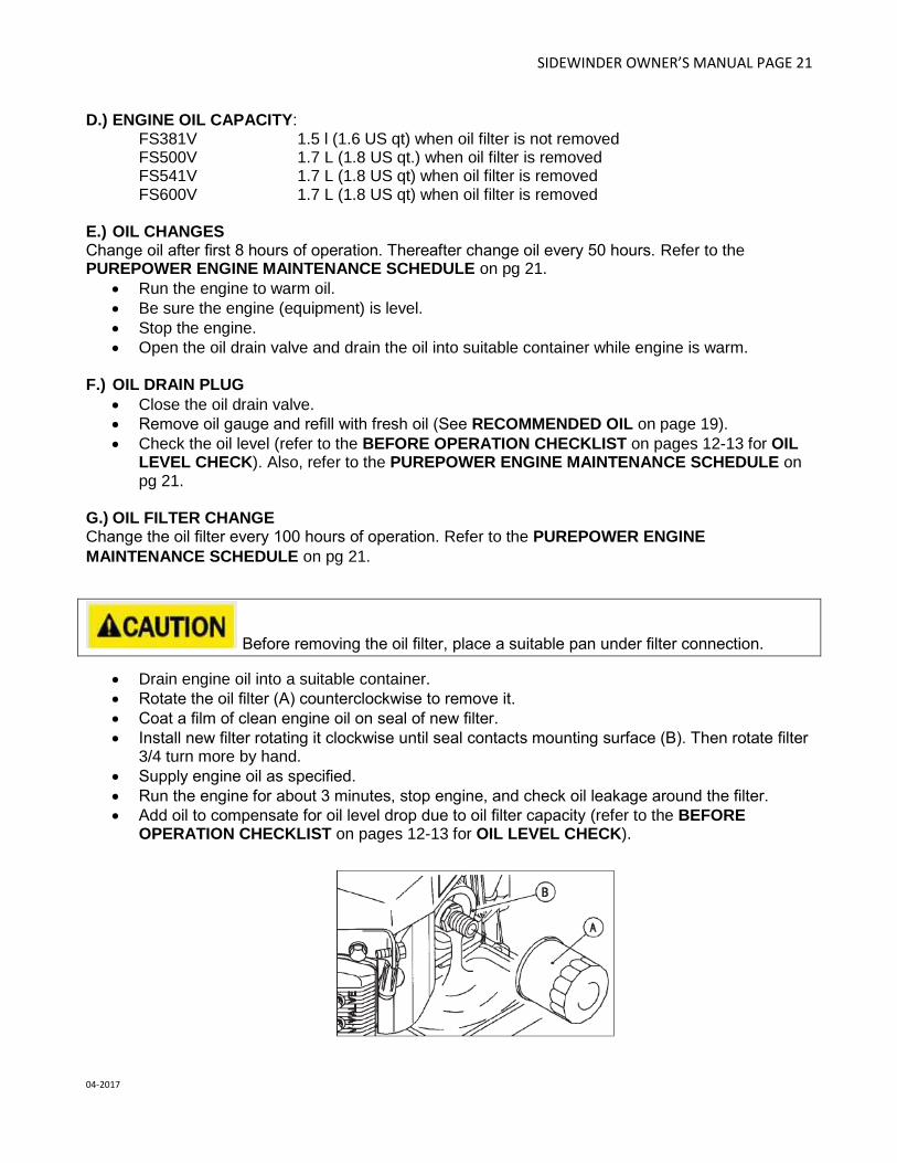
G.) OIL FILTER CHANGE Change the oil filter every 100 hours of operation. Refer to the PUREPOWER ENGINE
MAINTENANCE SCHEDULE on pg 21.
Before removing the oil filter, place a suitable pan under filter connection.
• Drain engine oil into a suitable container.
• Rotate the oil filter (A) counterclockwise to remove it.
• Coat a film of clean engine oil on seal of new filter.
• Install new filter rotating it clockwise until seal contacts mounting surface (B). Then rotate filter 3/4 turn more by hand.
• Supply engine oil as specified.
• Run the engine for about 3 minutes, stop engine, and check oil leakage around the filter.
• Add oil to compensate for oil level drop due to oil filter capacity (refer to the BEFORE OPERATION CHECKLIST on pages 12-13 for OIL LEVEL CHECK).

SIDEWINDER OWNER’S MANUAL PAGE 22
04-2017
PUREPOWER BY AZTEC ENGINE MAINTENANCE SCHEDULE
TROUBLESHOOTING - ENGINE
COMMON PROBLEMS & PROBABLE CAUSES SOLUTIONS
Engine cranks but will not start: Propane tank is empty Shutoff valve is closed Clogged, obstructed, kinked or cut fuel or vacuum line Spark plug lead disconnected Faulty ignition coil Faulty kill switch Faulty regulator
Refill propane tank Open valve Remove obstruction or replace line Connect lead to spark plug Replace ignition coil Replace switch Replace regulator
Engine starts hard: Faulty choke or throttle settings Clogged, obstructed, kinked or cut fuel or vacuum line Faulty regulator Low compression
Set controls to correct position Remove obstruction or replace line Replace regulator Have engine serviced by a trained technician
Engine will not crank: Battery is discharged Loose or faulty connections or wires Faulty ignition key switch or starter control switch
Charge or replace battery Tighten, repair or replace wires Repair or replace switch(es)
Engine overheats: Incorrect fuel settings Air intake filter screen or cooling fins clogged Low oil level
Have engine serviced by a trained technician Clean and clear debris or replace filter Check and add oil
Exhaust emissions or propane odor: Carburetor or regulator setting incorrect Dirty or clogged air filter Loose fittings, clamps or hoses cracked, hoses cut or
leaking
Have engine serviced by a trained technician Replace air filter Tighten or seal; check with soap and water solution, if bubbles appear, part is still leaking; replace
SIDEWINDER OWNER’S MANUAL PAGE 23
04-2017
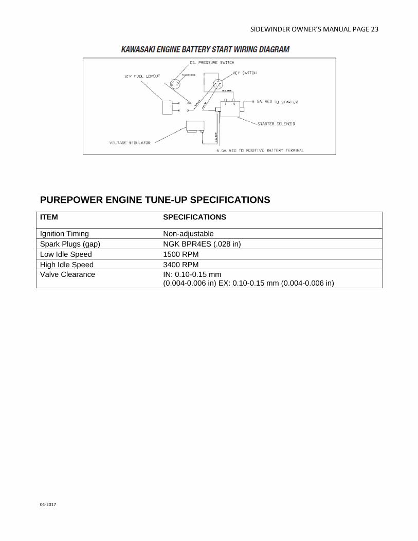
PUREPOWER ENGINE TUNE-UP SPECIFICATIONS
ITEM SPECIFICATIONS
Ignition Timing Non-adjustable
Spark Plugs (gap) NGK BPR4ES (.028 in)
Low Idle Speed 1500 RPM
High Idle Speed 3400 RPM
Valve Clearance IN: 0.10-0.15 mm (0.004-0.006 in) EX: 0.10-0.15 mm (0.004-0.006 in)

SIDEWINDER OWNER’S MANUAL PAGE 24
04-2017
AZTEC SIDEWINDER
QUICK START GUIDE
1.) Read, understand and observe all important
SAFETY INSTRUCTIONS before operating the machine (see pgs 3-8).
2.) Complete the BEFORE OPERATION
CHECKLIST on pgs 12-13. 3.) Make sure the machine is properly
maintained prior to use (see pgs 9, 15, 19-21).
4.) Make sure the LPG tank (A) is filled,
connected and checked for leaks (see pg 13).
5.) Open the LPG tank by turning the knob (B)
counter-clockwise. 6.) Set throttle lever (C) to idle/SLOW position 7.) Turn key (D) to start [ I ] position 8.) Move throttle lever (C) toward FAST position. If motor fails to start, return to Step 5 above. 9.) Set throttle lever (C) to desired operating speed and follow the moving machine (straight ahead) at moderate walking pace (keep moving).
C
D
A
B

SIDEWINDER OWNER’S MANUAL PAGE 25
04-2017
SIDEWINDER 24” & 30” WARNING LABEL LOCATIONS

SIDEWINDER OWNER’S MANUAL PAGE 26
04-2017
SIDEWINDER 30" BODY PARTS
ID # DESCRIPTION PART # QTY
1 TOGGLE & NUT 284-TB2-60 1
2 3/8-16 LOK-NUT 164-22834 5
3 LEFT BRACKET RIGHT BRACKET
(Included with #10, Part #370-010-971CCH)
1 1
4 T-HANDLE 370-27-25 1
5 HANDLE GRIP 224-987319 2
6 LOK-PIN 625-98404A385 1
7 KICK PLATE 283-010-04 1
8 3/8-16*3 BOLT 164-10131 1
9 20 # LP CYLINDER 293-20#STLMF 1
10 HANDLE ASSEMBLY 370-010-971CCH 1
11 6" WHEEL 156-XA-06251-12 2
12 SPANNER BUSHING 156-ZF-0812-39 2
13 AXEL & NUT 156-ALBZJ085408 2
14 BODY 370-010S-01 1
15 BRUSHDRIVE COVER 370-010-5-02 1
16 SPLASH SKIRT 010-5-971S 1
17 BELT COVER 370-01024S-03 1
18 THROTTLE CABLE 212-1 1
19 TRANS WHEEL BASE BRACKET 370-010-100 1
20 TRANS WHEEL BRACKET 370-010-200 1
21 5" SWIVEL WHEEL 156-010 1

SIDEWINDER OWNER’S MANUAL PAGE 27
04-2017
SIDEWINDER 30” UPPER DRIVE PARTS
ID # DESCRIPTION PART # QTY
1 3/8-16 HEX NUT 164-22004 2
2 TENSION PULLEY 188-V42B 1
3 BELT TENSIONER 010-962 I 1
4 ENGINE BELT 113-L537 1
5 5/16 FLAT WASHER 164-20156 1
6 NYLON BUSHING 196-71200 2
7 TENSION SPRING 173-7599-DWG 1
SIDEWINDER OWNER’S MANUAL PAGE 28
04-2017
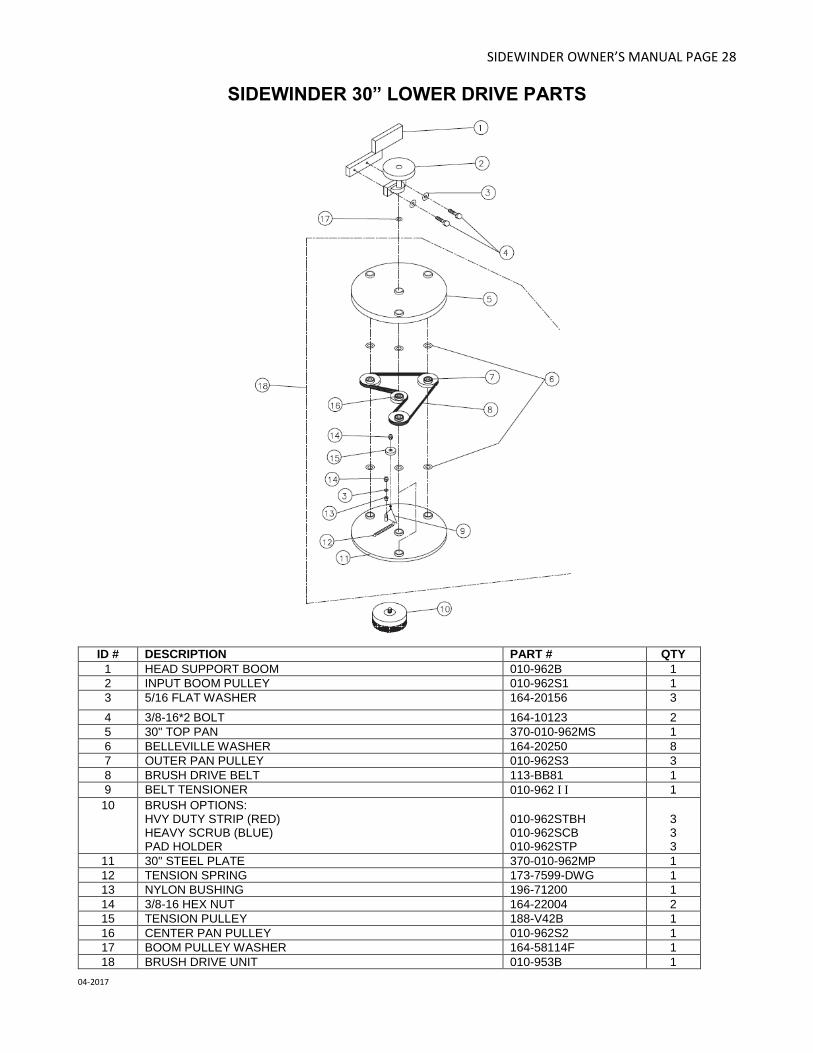
SIDEWINDER 30” LOWER DRIVE PARTS
ID # DESCRIPTION PART # QTY
1 HEAD SUPPORT BOOM 010-962B 1
2 INPUT BOOM PULLEY 010-962S1 1
3 5/16 FLAT WASHER 164-20156 3
4 3/8-16*2 BOLT 164-10123 2
5 30" TOP PAN 370-010-962MS 1
6 BELLEVILLE WASHER 164-20250 8
7 OUTER PAN PULLEY 010-962S3 3
8 BRUSH DRIVE BELT 113-BB81 1
9 BELT TENSIONER 010-962 I I 1
10 BRUSH OPTIONS: HVY DUTY STRIP (RED) HEAVY SCRUB (BLUE) PAD HOLDER
010-962STBH 010-962SCB 010-962STP
3 3 3
11 30" STEEL PLATE 370-010-962MP 1
12 TENSION SPRING 173-7599-DWG 1
13 NYLON BUSHING 196-71200 1
14 3/8-16 HEX NUT 164-22004 2
15 TENSION PULLEY 188-V42B 1
16 CENTER PAN PULLEY 010-962S2 1
17 BOOM PULLEY WASHER 164-58114F 1
18 BRUSH DRIVE UNIT 010-953B 1

SIDEWINDER OWNER’S MANUAL PAGE 29
04-2017
SIDEWINDER 24" BODY PARTS
ID # DESCRIPTION PART # QTY
1 TOGGLE & NUT 284-TB2-60 1
2 3/8-16 LOK-NUT 164-22834 5
3 LEFT BRACKET RIGHT BRACKET
(Included with #10, Part #010-971CCH)
1 1
4 T-HANDLE 370-27-25 1
5 HANDLE GRIP 224-987319 2
6 LOK-PIN 625-98404A385 1
7 KICK PLATE 283-010-04 1
8 3/8-16*3 BOLT 164-10131 1
9 20 # LP CYLINDER 293-20#STLMF 1
10 HANDLE ASSEMBLY 370-010-971CCH 1
11 6" WHEEL 156-XA-06251-12 2
12 SPANNER BUSHING 156-ZF-0812-39 2
13 AXEL & NUT 156-ALBZJ085408 2
14 BODY 370-010S-01 1
15 BRUSHDRIVE COVER 370-010-5-02 1
16 SPLASH SKIRT 01024S-971S 1
17 BELT COVER 370-01024S-03 1
18 THROTTLE CABLE 212-1 1
19 TRANS WHEEL BASE BRACKET 370-010-100 1
20 TRANS WHEEL BRACKET 370-010-200 1
21 5" SWIVEL WHEEL 156-010 1

SIDEWINDER OWNER’S MANUAL PAGE 30
04-2017
SIDEWINDER 24” UPPER DRIVE PARTS
ID # DESCRIPTION PART # QTY
1 3/8-16 HEX NUT 164-22004 2
2 TENSION PULLEY 188V42B 1
3 BELT TENSIONER 010-962 I 1
4 ENGINE BELT 113-L538 1
5 5/16 FLAT WASHER 164-20156 1
6 NYLON BUSHING 196-71200 2
7 TENSION SPRING 173-7599-DWG 1

SIDEWINDER OWNER’S MANUAL PAGE 31
04-2017
SIDEWINDER 24” LOWER DRIVE PARTS
ID # DESCRIPTION PART # QTY
1 HEAD SUPPORT BOOM 01024-962B 1
2 INPUT BOOM PULLEY 010S-962S1 1
3 5/16 FLAT WASHER 164-20156 3
4 3/8-16*2 BOLT 164-10123 2
5 24" TOP PAN 370-01024-962MS 1
6 BELLEVILLE WASHER 164-20250 8
7 OUTER PAN PULLEY 010-962S3 3
8 BRUSH DRIVE BELT 113-BB68 1
9 BELT TENSIONER 01024-962 I I 1
10 BRUSH OPTIONS: HVY DUTY STRIP (ORANGE) HEAVY SCRUB (BLUE) PAD HOLDER
010-962STBH 01024-962SCB 01024-962STP
3 3 3
11 24" STEEL PLATE 370-01024-962MP 1
12 TENSION SPRING 173-7501-DWG 1
13 NYLON BUSHING 196-71200 1
14 3/8-16 HEX NUT 164-22004 2
15 TENSION PULLEY 188-V42B 1
16 CENTER PAN PULLEY 010-962S2 1
17 BOOM PULLEY WASHER 164-58114F 1
18 BRUSH DRIVE UNIT 01024-953B 1
SIDEWINDER OWNER’S MANUAL PAGE 32
04-2017
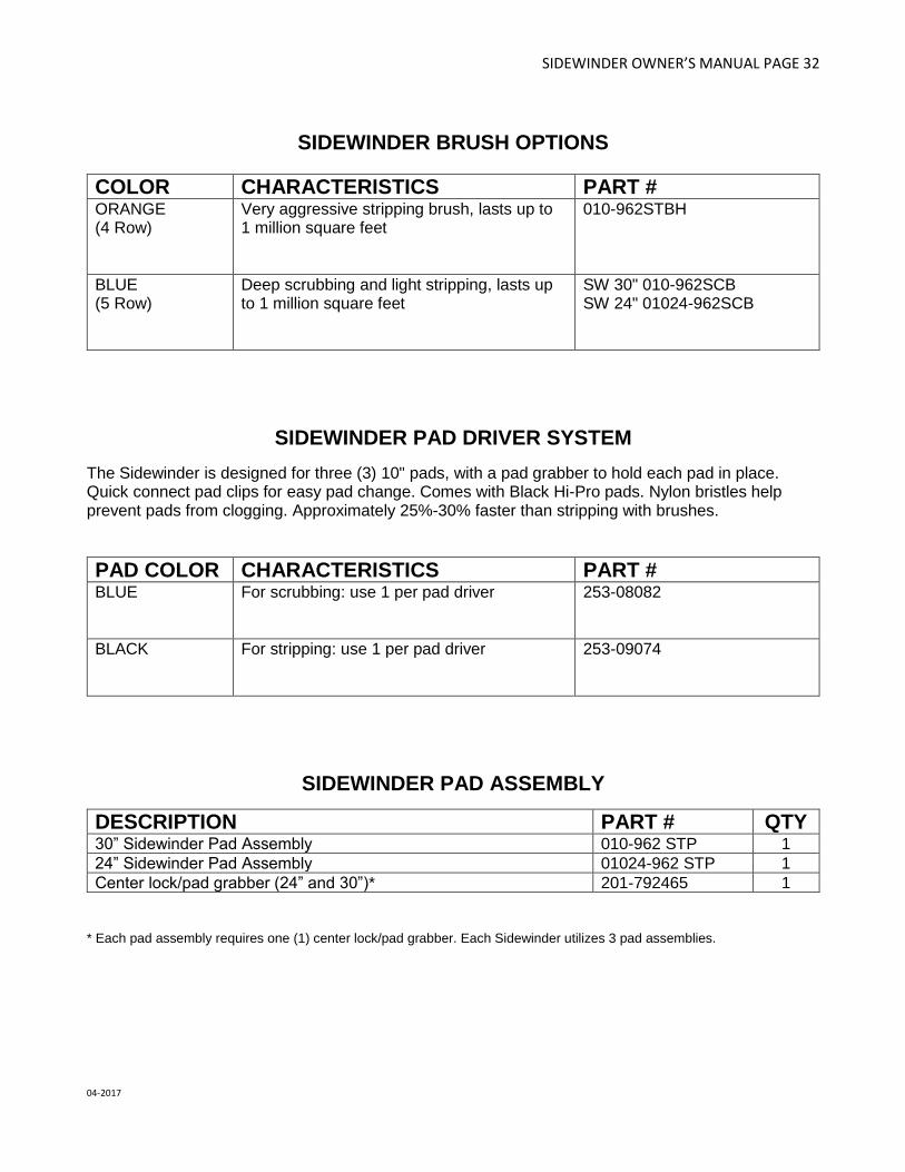
SIDEWINDER BRUSH OPTIONS
COLOR CHARACTERISTICS PART # ORANGE (4 Row)
Very aggressive stripping brush, lasts up to 1 million square feet
010-962STBH
BLUE (5 Row)
Deep scrubbing and light stripping, lasts up to 1 million square feet
SW 30" 010-962SCB SW 24" 01024-962SCB
SIDEWINDER PAD DRIVER SYSTEM
The Sidewinder is designed for three (3) 10" pads, with a pad grabber to hold each pad in place. Quick connect pad clips for easy pad change. Comes with Black Hi-Pro pads. Nylon bristles help prevent pads from clogging. Approximately 25%-30% faster than stripping with brushes.
PAD COLOR CHARACTERISTICS PART # BLUE For scrubbing: use 1 per pad driver
253-08082
BLACK For stripping: use 1 per pad driver
253-09074
SIDEWINDER PAD ASSEMBLY
DESCRIPTION PART # QTY 30” Sidewinder Pad Assembly 010-962 STP 1
24” Sidewinder Pad Assembly 01024-962 STP 1
Center lock/pad grabber (24” and 30”)* 201-792465 1
* Each pad assembly requires one (1) center lock/pad grabber. Each Sidewinder utilizes 3 pad assemblies.

SIDEWINDER OWNER’S MANUAL PAGE 33
04-2017
FUEL SYSTEM 12V STARTER PARTS LIST
ID # DESCRIPTION PART # QTY
1 QUICK COUPLER 152-700 1
2 LPG HOSE 17" 267-P5561-0410 1
3 FUEL HOSE FITTING 166-62039-B 1
4 FUEL LOK-OUT (12 VOLT) 152-N3-0173-1 1
5 FUEL REGULATOR (T-60E) 152-500 1
SIDEWINDER OWNER’S MANUAL PAGE 34
04-2017
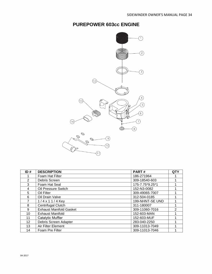
PUREPOWER 603cc ENGINE
ID # DESCRIPTION PART # QTY
1 Foam Hat Filter 186-271964 1
2 Debris Screen 309-18540-603 1
3 Foam Hat Seal 175-7.75*9.25*1 1
4 Oil Pressure Switch 152-N3-0082 1
5 Oil Filter 309-49065-7007 1
6 Oil Drain Valve 312-504-0185 1
7 1 / 4 x 1 1 / 4 Key 199-NHNT-SE UND 1
8 Centrifugal Clutch 311-180007 1
9 Exhaust Manifold Gasket 309-11060-7016 2
10 Exhaust Manifold 152-603-MAN 1
11 Catalytic Muffler 152-603-MUF 1
12 Debris Screen Adapter 283-040-2250 1
13 Air Filter Element 309-11013-7049 1
14 Foam Pre Filter 309-11013-7046 1

SIDEWINDER OWNER’S MANUAL PAGE 35
04-2017
AZTEC SIDEWINDER 24” & 30” WARRANTY
This warranty is limited as follows:
Component Term of Warranty
Engine 2 yrs from engine manufacturer Fuel System 1 yr LPG Tank 1 yr on valve, 3 yrs on cylinder from date of mfgr Body Parts 1 yr Battery 1 yr from battery mfgr Centrifugal Clutch 1 yr The warranty does not apply to certain consumable or wear parts such as: Brushes Belts Engine tune up parts Aztec Products, Inc. warrants its products to be free from defects in material and workmanship for a period of one year from the date of sale. All engines are warranted by the manufacturers for a period of two years when engine maintenance schedules are followed. The warranty does not apply to damage or failure caused by abuse, misuse, neglect, disassembly, alteration, unauthorized modification or repair, lack of proper maintenance, theft or damage by freight carriers. The warranty applies to parts, labor, and ground freight only. Aztec is not liable for transportation to or from repair centers or travel for on-site repairs. Aztec Products, Inc. will not be liable for incidental or consequential damages arising from the use of any of its products, whether defective or not. Aztec Products, Inc. agrees, at its discretion, to repair or replace at its own expense any product or part(s) which examination proves to be defective in workmanship or materials provided that the purchaser notifies Aztec Products, Inc. directly within the warranty period and follows the Return Goods Policy. Engine repairs may be performed at engine manufacturer’s service centers. For your closest center you may call Kawasaki: 616-949-6500. To obtain parts warranty, the following procedures must be followed: 1. Customer must call Aztec Products, Inc. for an RGA (Return Goods Authorization) Number.
2. We maintain the serial number, date of shipment or sale, and customer name on each piece of equipment sold. If
you were the purchaser, please reference that information on your request for replacement or repair. If you
purchased the equipment through a distributor, please contact them first. If you are not satisfied, contact Aztec
and give us the distributor name, purchase date, and the serial number of the product.
3. The defective part must be returned via ground freight prepaid to Aztec Products, Inc. with an RGA number
accompanied by a copy to the original purchase invoice. Aztec is not responsible for the cost of packaging
inbound freight, nor inbound freight damage. Pack machine carefully.
4. Only Aztec Products, Inc. or its authorized dealers may make warranty repairs on Aztec Products, Inc. products.
Others do so at their own risk and expense.
5. We also offer to do warranty related repairs free of charge at our facility. Arrangements must be made in
advance as outlined above. We will not accept freight collect returns or returns that do not indicate the RGA
number on the packing list.
The need for proper maintenance and care for this product cannot be overstated. Poor maintenance, neglect or
abuse will void the warranty and prove to be very expensive.
You have purchased a quality product. Each of its components have been tested and approved for use by Aztec
Products, Inc. It is unlikely that you will ever have a warranty claim if you properly maintain your machine.
This warranty is non-transferable. AZTEC PRODUCTS, INC. • www.aztecprocucts.com
201 Commerce Drive • Montgomeryville, PA 18936 • 800-331-1423 • Fax 215-393-