Sideband Algorithm for Automatic Wind Turbine Gearbox Fault ...
12
NREL is a national laboratory of the U.S. Department of Energy, Office of Energy Efficiency & Renewable Energy, operated by the Alliance for Sustainable Energy, LLC. Contract No. DE-AC36-08GO28308 Sideband Algorithm for Automatic Wind Turbine Gearbox Fault Detection and Diagnosis Preprint D. Zappalà, P. Tavner, and C. Crabtree Durham University S. Sheng National Renewable Energy Laboratory To be presented at the European Wind Energy Association 2013 Annual Event Vienna, Austria February 4-7, 2013 Conference Paper NREL/CP-5000-57395 January 2013
Transcript of Sideband Algorithm for Automatic Wind Turbine Gearbox Fault ...
NREL is a national laboratory of the U.S. Department of Energy, Office of Energy Efficiency & Renewable Energy, operated by the Alliance for Sustainable Energy, LLC.
Contract No. DE-AC36-08GO28308
Sideband Algorithm for Automatic Wind Turbine Gearbox Fault Detection and Diagnosis Preprint D. Zappalà, P. Tavner, and C. Crabtree Durham University
S. Sheng National Renewable Energy Laboratory
To be presented at the European Wind Energy Association 2013 Annual Event Vienna, Austria February 4-7, 2013
Conference Paper NREL/CP-5000-57395 January 2013
NOTICE
The submitted manuscript has been offered by an employee of the Alliance for Sustainable Energy, LLC (Alliance), a contractor of the US Government under Contract No. DE-AC36-08GO28308. Accordingly, the US Government and Alliance retain a nonexclusive royalty-free license to publish or reproduce the published form of this contribution, or allow others to do so, for US Government purposes.
This report was prepared as an account of work sponsored by an agency of the United States government. Neither the United States government nor any agency thereof, nor any of their employees, makes any warranty, express or implied, or assumes any legal liability or responsibility for the accuracy, completeness, or usefulness of any information, apparatus, product, or process disclosed, or represents that its use would not infringe privately owned rights. Reference herein to any specific commercial product, process, or service by trade name, trademark, manufacturer, or otherwise does not necessarily constitute or imply its endorsement, recommendation, or favoring by the United States government or any agency thereof. The views and opinions of authors expressed herein do not necessarily state or reflect those of the United States government or any agency thereof.
Available electronically at http://www.osti.gov/bridge
Available for a processing fee to U.S. Department of Energy and its contractors, in paper, from:
U.S. Department of Energy Office of Scientific and Technical Information P.O. Box 62 Oak Ridge, TN 37831-0062 phone: 865.576.8401 fax: 865.576.5728 email: mailto:[email protected]
Available for sale to the public, in paper, from:
U.S. Department of Commerce National Technical Information Service 5285 Port Royal Road Springfield, VA 22161 phone: 800.553.6847 fax: 703.605.6900 email: [email protected] online ordering: http://www.ntis.gov/help/ordermethods.aspx
Cover Photos: (left to right) PIX 16416, PIX 17423, PIX 16560, PIX 17613, PIX 17436, PIX 17721
Printed on paper containing at least 50% wastepaper, including 10% post consumer waste.
1
Sideband Algorithm for Automatic Wind Turbine Gearbox Fault Detection and Diagnosis
Donatella Zappalà Peter J. Tavner School of Engineering and Computing Sciences School of Engineering and Computing Sciences
Durham University, UK Durham University, UK [email protected] [email protected]
Christopher J. Crabtree Shuangwen Sheng
School of Engineering and Computing Sciences National Renewable Energy Laboratory (NREL) Durham University, UK Golden, Colorado, United States
[email protected] [email protected]
Abstract
Improving the availability of wind turbines (WT) is critical to minimise the cost of wind energy, especially for offshore installations. Because gearbox downtime has a significant impact on WT availabilities, the development of reliable and cost-effective gearbox condition monitoring systems (CMSs) is of great concern to the wind industry. Timely detection and diagnosis of developing gear defects within a gearbox is an essential part of minimizing unplanned downtime of wind turbines. Monitoring signals from WT gearboxes are highly non-stationary because turbine load and speed vary continuously with time. Manual handling of large amounts of monitoring data is time-consuming and costly, and is one of the main limitations of most current CMSs. Therefore, automated algorithms are required.
This paper presents a fault detection algorithm for incorporation into a commercial CMS for automatic gear fault detection and diagnosis. Based on the experimental evidence from the Durham condition monitoring test rig, a gear condition indicator has been proposed to evaluate the gear damage during non-stationary load and speed operating conditions. The algorithm allows the assessment of gear fault severity by tracking progressive tooth gear damage during variable speed and load operating conditions of the test rig.
The performance of the proposed technique has then been successfully tested on signals from a field
test of a full-size wind turbine gearbox that has sustained gear damage.
Results show that the proposed technique proves efficient and reliable for detecting gear damage. Once implemented into WT CMSs, this algorithm can automate data interpretation, reducing the quantity of information that WT operators must handle.
Keywords: wind turbine, gearbox, condition monitoring, gear tooth fault, vibration analysis
1 Introduction
Achieving high WT availability is paramount to providing affordable and cost-effective wind energy, especially with the current growth in turbine size and capacity, and the installation in increasingly remote and less accessible offshore locations. To make wind power more competitive compared to conventional sources, it is necessary to reduce turbine downtime and increase reliability [1]. The development of reliable and cost-effective online condition monitoring (CM) techniques with automatic damage detection and diagnosis of WT components can help achieve predictive, condition-based maintenance. This will reduce the operation and maintenance (O&M) costs and thereby the cost of wind energy. Gearbox faults, with high replacement costs, complex repair procedures, and revenue loss caused by long downtime [2], are widely considered a leading issue for WT drive train CM.
In this paper, the effect of gear tooth fault severity on the gearbox vibration signature is investigated using
2
experimental results obtained on the Wind Turbine Condition Monitoring Test Rig (WTCMTR) at Durham University. A frequency tracking algorithm that automatically detects and diagnoses gear tooth faults is proposed and discussed. The performance of the proposed technique is then tested using vibration signals from a real 750-kW wind turbine gearbox that has sustained gear damage from its field test.
2 Wind Turbine Gearbox Condition Monitoring
Among the various wind turbine components, the gearbox has been shown to cause the longest downtime [2,3] and is the most costly to maintain throughout a turbine’s 20-year-plus design life [4]. Typical WT gearbox failure modes are gear tooth damage and bearing faults [5]. A recent study [6] has shown that the gearbox alone could be responsible for up to one-third of all lost onshore WT availability.
This problem is emphasised offshore where harsh weather and sea conditions could prevent maintenance or component replacement for long periods of time. Few reliability data are still publicly available for offshore WTs. However, 3 years of available data from Egmond aan Zee wind farm in the Netherlands [7] show how the gearbox downtime caused 55% of the total wind farm downtime [8].
The main WT Operator concerns about gearbox reliability, particularly offshore, are: high replacement costs following a failure; complex repair procedures that incur high logistics costs and require favourable weather conditions; and high revenue losses caused by long downtime between failures and repair completion [5]. Consequently, the gearbox has become an essential part of the current commercial available WT CMSs. Timely and reliable detection and diagnosis of developing gear defects within a gearbox is an essential part of minimizing unplanned downtime of wind turbines.
The most popular CM approach for the gearbox is vibration monitoring using Fourier transform analysis [9]. WTs are variable load and speed systems operating under highly dynamic conditions. This results in CM signals that vary significantly in both
magnitude and spectral content. The frequent false alarms and the costly specialist knowledge that is required for manual interpretation of the complex vibration data have discouraged WT Operators from making wider use of CMS. This happens despite the fact that these systems are fitted to the majority of large WTs (>1.5 MW) in Europe [10]. Moreover, with the growth of the WT population, especially offshore, the manual examination and comparison of the CM data will be impractical unless a simplified monitoring process is introduced.
Current efforts in the wind CM industry are aimed at automating data interpretation and improving the accuracy and reliability of diagnostic decisions, especially in the light of impending large-scale, offshore wind-farm generation. This study attempts to target this research area by experimentally defining an algorithm that could be incorporated into current CMS for automatic gear fault detection and diagnosis. This algorithm can reduce the quantity of information that the WT operators must handle, providing improved detection and timely decision-making capabilities.
3 WT Condition Monitoring Test Rig
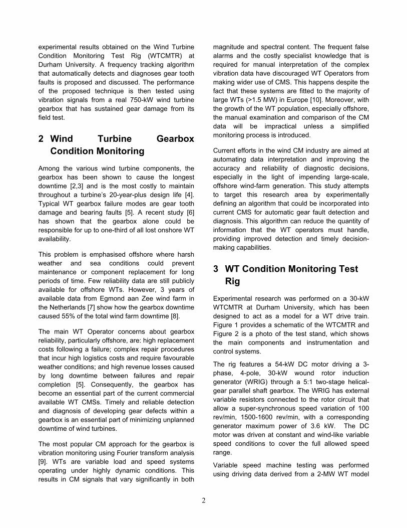
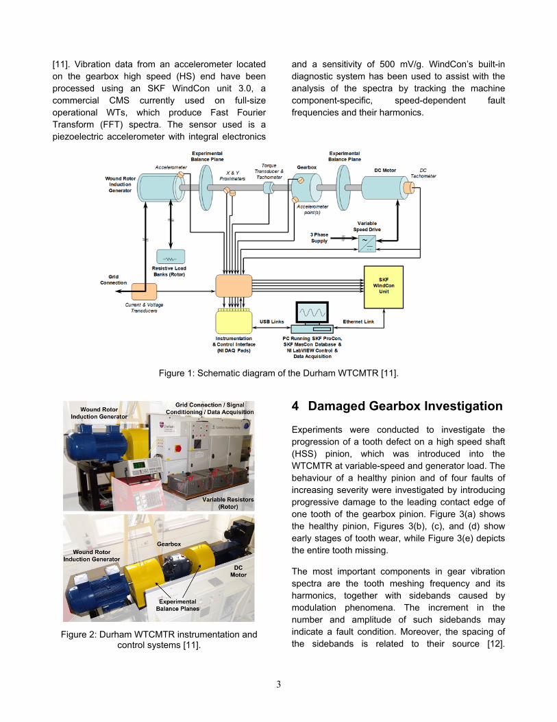
Experimental research was performed on a 30-kW WTCMTR at Durham University, which has been designed to act as a model for a WT drive train. Figure 1 provides a schematic of the WTCMTR and Figure 2 is a photo of the test stand, which shows the main components and instrumentation and control systems.
The rig features a 54-kW DC motor driving a 3-phase, 4-pole, 30-kW wound rotor induction generator (WRIG) through a 5:1 two-stage helical-gear parallel shaft gearbox. The WRIG has external variable resistors connected to the rotor circuit that allow a super-synchronous speed variation of 100 rev/min, 1500-1600 rev/min, with a corresponding generator maximum power of 3.6 kW. The DC motor was driven at constant and wind-like variable speed conditions to cover the full allowed speed range.
Variable speed machine testing was performed using driving data derived from a 2-MW WT model
3
[11]. Vibration data from an accelerometer located on the gearbox high speed (HS) end have been processed using an SKF WindCon unit 3.0, a commercial CMS currently used on full-size operational WTs, which produce Fast Fourier Transform (FFT) spectra. The sensor used is a piezoelectric accelerometer with integral electronics
and a sensitivity of 500 mV/g. WindCon’s built-in diagnostic system has been used to assist with the analysis of the spectra by tracking the machine component-specific, speed-dependent fault frequencies and their harmonics.
Figure 1: Schematic diagram of the Durham WTCMTR [11].
Figure 2: Durham WTCMTR instrumentation and
control systems [11].
4 Damaged Gearbox Investigation
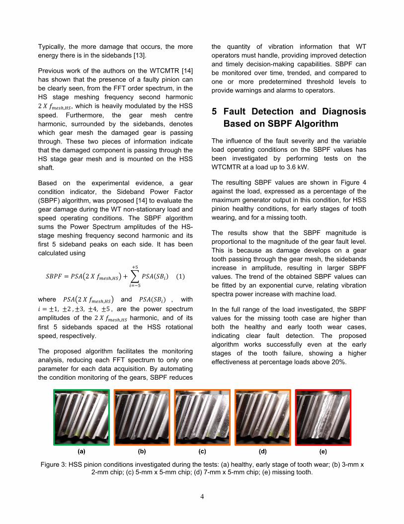
Experiments were conducted to investigate the progression of a tooth defect on a high speed shaft (HSS) pinion, which was introduced into the WTCMTR at variable-speed and generator load. The behaviour of a healthy pinion and of four faults of increasing severity were investigated by introducing progressive damage to the leading contact edge of one tooth of the gearbox pinion. Figure 3(a) shows the healthy pinion, Figures 3(b), (c), and (d) show early stages of tooth wear, while Figure 3(e) depicts the entire tooth missing.
The most important components in gear vibration spectra are the tooth meshing frequency and its harmonics, together with sidebands caused by modulation phenomena. The increment in the number and amplitude of such sidebands may indicate a fault condition. Moreover, the spacing of the sidebands is related to their source [12].
4
Typically, the more damage that occurs, the more energy there is in the sidebands [13].
Previous work of the authors on the WTCMTR [14] has shown that the presence of a faulty pinion can be clearly seen, from the FFT order spectrum, in the HS stage meshing frequency second harmonic 2 𝑋 𝑓𝑚𝑒𝑠ℎ,𝐻𝑆, which is heavily modulated by the HSS speed. Furthermore, the gear mesh centre harmonic, surrounded by the sidebands, denotes which gear mesh the damaged gear is passing through. These two pieces of information indicate that the damaged component is passing through the HS stage gear mesh and is mounted on the HSS shaft.
Based on the experimental evidence, a gear condition indicator, the Sideband Power Factor (SBPF) algorithm, was proposed [14] to evaluate the gear damage during the WT non-stationary load and speed operating conditions. The SBPF algorithm sums the Power Spectrum amplitudes of the HS-stage meshing frequency second harmonic and its first 5 sideband peaks on each side. It has been calculated using
𝑆𝐵𝑃𝐹 = 𝑃𝑆𝐴�2 𝑋 𝑓𝑚𝑒𝑠ℎ,𝐻𝑆� + � 𝑃𝑆𝐴(𝑆𝐵𝑖) (1)+5
𝑖=−5
where 𝑃𝑆𝐴�2 𝑋 𝑓𝑚𝑒𝑠ℎ,𝐻𝑆� and 𝑃𝑆𝐴(𝑆𝐵𝑖) , with 𝑖 = ±1, ±2 , ±3, ±4, ±5 , are the power spectrum amplitudes of the 2 𝑋 𝑓𝑚𝑒𝑠ℎ,𝐻𝑆 harmonic, and of its first 5 sidebands spaced at the HSS rotational speed, respectively.
The proposed algorithm facilitates the monitoring analysis, reducing each FFT spectrum to only one parameter for each data acquisition. By automating the condition monitoring of the gears, SBPF reduces
the quantity of vibration information that WT operators must handle, providing improved detection and timely decision-making capabilities. SBPF can be monitored over time, trended, and compared to one or more predetermined threshold levels to provide warnings and alarms to operators.
5 Fault Detection and Diagnosis Based on SBPF Algorithm
The influence of the fault severity and the variable load operating conditions on the SBPF values has been investigated by performing tests on the WTCMTR at a load up to 3.6 kW.
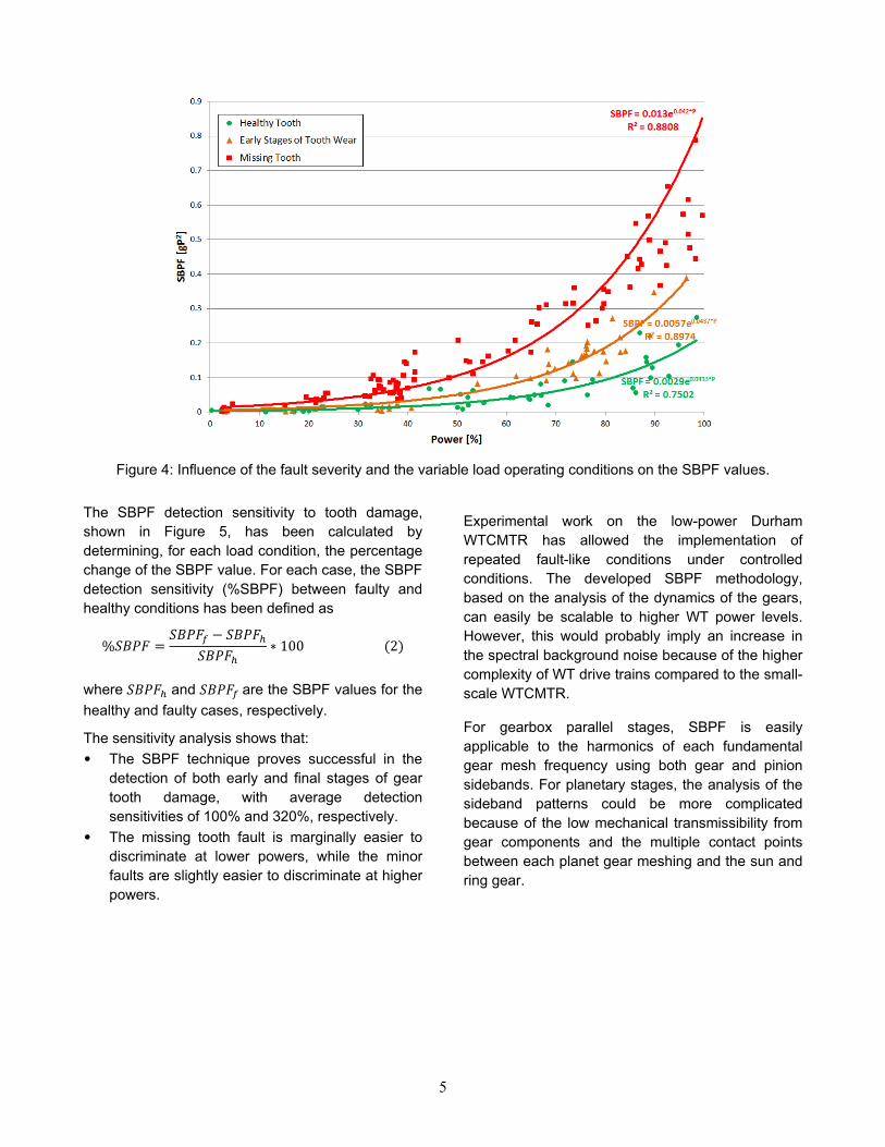
The resulting SBPF values are shown in Figure 4 against the load, expressed as a percentage of the maximum generator output in this condition, for HSS pinion healthy conditions, for early stages of tooth wearing, and for a missing tooth.
The results show that the SBPF magnitude is proportional to the magnitude of the gear fault level. This is because as damage develops on a gear tooth passing through the gear mesh, the sidebands increase in amplitude, resulting in larger SBPF values. The trend of the obtained SBPF values can be fitted by an exponential curve, relating vibration spectra power increase with machine load.
In the full range of the load investigated, the SBPF values for the missing tooth case are higher than both the healthy and early tooth wear cases, indicating clear fault detection. The proposed algorithm works successfully even at the early stages of the tooth failure, showing a higher effectiveness at percentage loads above 20%.
Figure 3: HSS pinion conditions investigated during the tests: (a) healthy, early stage of tooth wear; (b) 3-mm x
2-mm chip; (c) 5-mm x 5-mm chip; (d) 7-mm x 5-mm chip; (e) missing tooth.
5
Figure 4: Influence of the fault severity and the variable load operating conditions on the SBPF values.
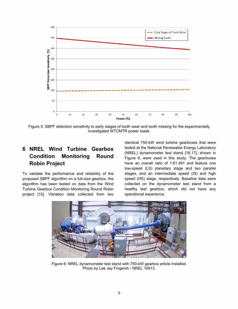
The SBPF detection sensitivity to tooth damage, shown in Figure 5, has been calculated by determining, for each load condition, the percentage change of the SBPF value. For each case, the SBPF detection sensitivity (%SBPF) between faulty and healthy conditions has been defined as
%𝑆𝐵𝑃𝐹 =𝑆𝐵𝑃𝐹𝑓 − 𝑆𝐵𝑃𝐹ℎ
𝑆𝐵𝑃𝐹ℎ∗ 100 (2)
where 𝑆𝐵𝑃𝐹ℎ and 𝑆𝐵𝑃𝐹𝑓 are the SBPF values for the healthy and faulty cases, respectively.
The sensitivity analysis shows that: • The SBPF technique proves successful in the
detection of both early and final stages of gear tooth damage, with average detection sensitivities of 100% and 320%, respectively.
• The missing tooth fault is marginally easier to discriminate at lower powers, while the minor faults are slightly easier to discriminate at higher powers.
Experimental work on the low-power Durham WTCMTR has allowed the implementation of repeated fault-like conditions under controlled conditions. The developed SBPF methodology, based on the analysis of the dynamics of the gears, can easily be scalable to higher WT power levels. However, this would probably imply an increase in the spectral background noise because of the higher complexity of WT drive trains compared to the small-scale WTCMTR.
For gearbox parallel stages, SBPF is easily applicable to the harmonics of each fundamental gear mesh frequency using both gear and pinion sidebands. For planetary stages, the analysis of the sideband patterns could be more complicated because of the low mechanical transmissibility from gear components and the multiple contact points between each planet gear meshing and the sun and ring gear.
6
Figure 5: SBPF detection sensitivity to early stages of tooth wear and tooth missing for the experimentally
investigated WTCMTR power loads.
6 NREL Wind Turbine Gearbox Condition Monitoring Round Robin Project
To validate the performance and reliability of the proposed SBPF algorithm on a full-size gearbox, the algorithm has been tested on data from the Wind Turbine Gearbox Condition Monitoring Round Robin project [15]. Vibration data collected from two
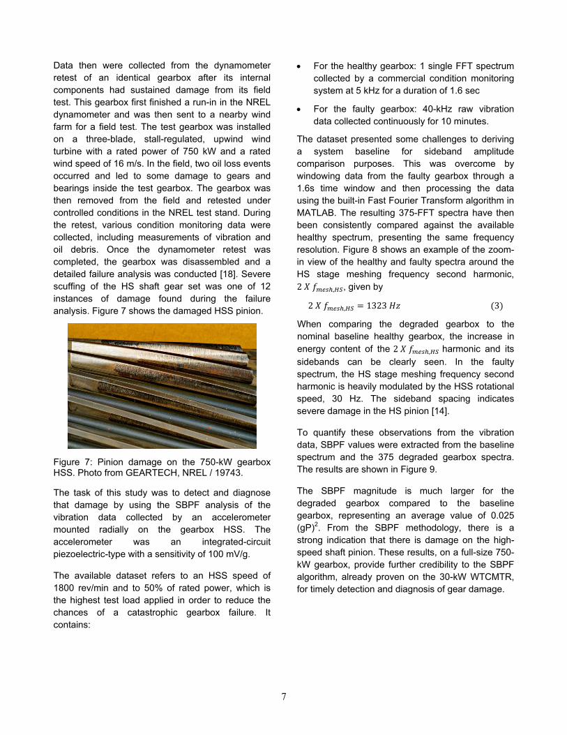
identical 750-kW wind turbine gearboxes that were tested at the National Renewable Energy Laboratory (NREL) dynamometer test stand [16,17], shown in Figure 6, were used in this study. The gearboxes have an overall ratio of 1:81.491 and feature one low-speed (LS) planetary stage and two parallel stages, and an intermediate speed (IS) and high speed (HS) stage, respectively. Baseline data were collected on the dynamometer test stand from a healthy test gearbox, which did not have any operational experience.
Figure 6: NREL dynamometer test stand with 750-kW gearbox article installed.
Photo by Lee Jay Fingersh / NREL 16913.
7
Data then were collected from the dynamometer retest of an identical gearbox after its internal components had sustained damage from its field test. This gearbox first finished a run-in in the NREL dynamometer and was then sent to a nearby wind farm for a field test. The test gearbox was installed on a three-blade, stall-regulated, upwind wind turbine with a rated power of 750 kW and a rated wind speed of 16 m/s. In the field, two oil loss events occurred and led to some damage to gears and bearings inside the test gearbox. The gearbox was then removed from the field and retested under controlled conditions in the NREL test stand. During the retest, various condition monitoring data were collected, including measurements of vibration and oil debris. Once the dynamometer retest was completed, the gearbox was disassembled and a detailed failure analysis was conducted [18]. Severe scuffing of the HS shaft gear set was one of 12 instances of damage found during the failure analysis. Figure 7 shows the damaged HSS pinion.
Figure 7: Pinion damage on the 750-kW gearbox HSS. Photo from GEARTECH, NREL / 19743.
The task of this study was to detect and diagnose that damage by using the SBPF analysis of the vibration data collected by an accelerometer mounted radially on the gearbox HSS. The accelerometer was an integrated-circuit piezoelectric-type with a sensitivity of 100 mV/g.
The available dataset refers to an HSS speed of 1800 rev/min and to 50% of rated power, which is the highest test load applied in order to reduce the chances of a catastrophic gearbox failure. It contains:
• For the healthy gearbox: 1 single FFT spectrum collected by a commercial condition monitoring system at 5 kHz for a duration of 1.6 sec
• For the faulty gearbox: 40-kHz raw vibration data collected continuously for 10 minutes.
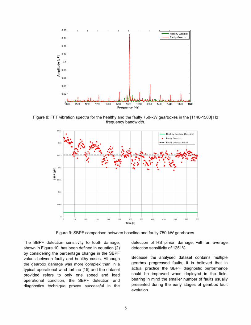
The dataset presented some challenges to deriving a system baseline for sideband amplitude comparison purposes. This was overcome by windowing data from the faulty gearbox through a 1.6s time window and then processing the data using the built-in Fast Fourier Transform algorithm in MATLAB. The resulting 375-FFT spectra have then been consistently compared against the available healthy spectrum, presenting the same frequency resolution. Figure 8 shows an example of the zoom-in view of the healthy and faulty spectra around the HS stage meshing frequency second harmonic, 2 𝑋 𝑓𝑚𝑒𝑠ℎ,𝐻𝑆, given by
2 𝑋 𝑓𝑚𝑒𝑠ℎ,𝐻𝑆 = 1323 𝐻𝑧 (3)
When comparing the degraded gearbox to the nominal baseline healthy gearbox, the increase in energy content of the 2 𝑋 𝑓𝑚𝑒𝑠ℎ,𝐻𝑆 harmonic and its sidebands can be clearly seen. In the faulty spectrum, the HS stage meshing frequency second harmonic is heavily modulated by the HSS rotational speed, 30 Hz. The sideband spacing indicates severe damage in the HS pinion [14].
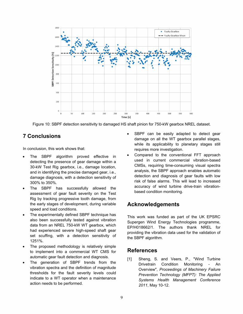
To quantify these observations from the vibration data, SBPF values were extracted from the baseline spectrum and the 375 degraded gearbox spectra. The results are shown in Figure 9.
The SBPF magnitude is much larger for the degraded gearbox compared to the baseline gearbox, representing an average value of 0.025 (gP)2. From the SBPF methodology, there is a strong indication that there is damage on the high-speed shaft pinion. These results, on a full-size 750-kW gearbox, provide further credibility to the SBPF algorithm, already proven on the 30-kW WTCMTR, for timely detection and diagnosis of gear damage.
8
Figure 8: FFT vibration spectra for the healthy and the faulty 750-kW gearboxes in the [1140-1500] Hz frequency bandwidth.
Figure 9: SBPF comparison between baseline and faulty 750-kW gearboxes.
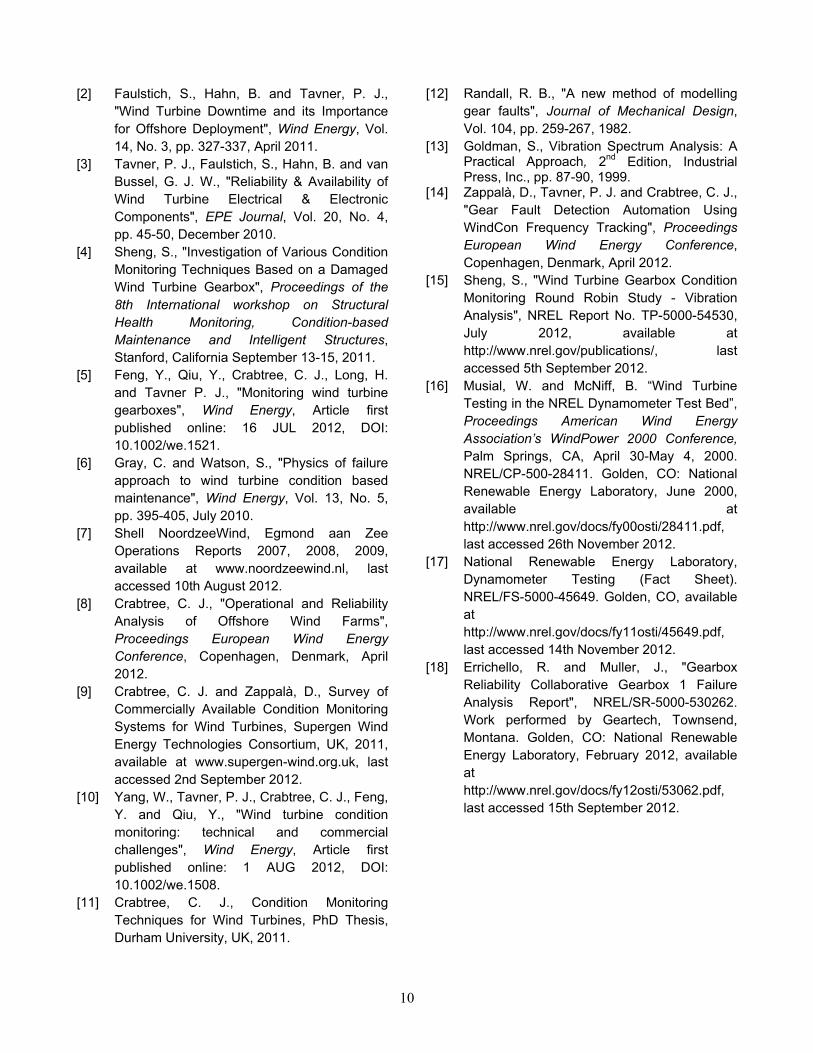
The SBPF detection sensitivity to tooth damage, shown in Figure 10, has been defined in equation (2) by considering the percentage change in the SBPF values between faulty and healthy cases. Although the gearbox damage was more complex than in a typical operational wind turbine [15] and the dataset provided refers to only one speed and load operational condition, the SBPF detection and diagnostics technique proves successful in the
detection of HS pinion damage, with an average detection sensitivity of 1251%.
Because the analysed dataset contains multiple gearbox progressed faults, it is believed that in actual practice the SBPF diagnostic performance could be improved when deployed in the field, bearing in mind the smaller number of faults usually presented during the early stages of gearbox fault evolution.
1140 1170 1200 1230 1260 1290 1320 1350 1380 1410 1440 1470 150015000
0.02
0.04
0.06
0.08
0.1
0.12
0.14
0.16
0.18
Frequency [Hz]
Am
plitu
de [g
P]
Healthy GearboxFaulty Gearbox
9
Figure 10: SBPF detection sensitivity to damaged HS shaft pinion for 750-kW gearbox NREL dataset.
7 Conclusions
In conclusion, this work shows that:
• The SBPF algorithm proved effective in detecting the presence of gear damage within a 30-kW Test Rig gearbox, i.e., damage location, and in identifying the precise damaged gear, i.e., damage diagnosis, with a detection sensitivity of 300% to 350%.
• The SBPF has successfully allowed the assessment of gear fault severity on the Test Rig by tracking progressive tooth damage, from the early stages of development, during variable speed and load conditions.
• The experimentally defined SBPF technique has also been successfully tested against vibration data from an NREL 750-kW WT gearbox, which had experienced severe high-speed shaft gear set scuffing, with a detection sensitivity of 1251%.
• The proposed methodology is relatively simple to implement into a commercial WT CMS for automatic gear fault detection and diagnosis.
• The generation of SBPF trends from the vibration spectra and the definition of magnitude thresholds for the fault severity levels could indicate to a WT operator when a maintenance action needs to be performed.
• SBPF can be easily adapted to detect gear damage on all the WT gearbox parallel stages, while its applicability to planetary stages still requires more investigation.
• Compared to the conventional FFT approach used in current commercial vibration-based CMSs, requiring time-consuming visual spectra analysis, the SBPF approach enables automatic detection and diagnosis of gear faults with low risk of false alarms. This will lead to increased accuracy of wind turbine drive-train vibration-based condition monitoring.
Acknowledgements
This work was funded as part of the UK EPSRC Supergen Wind Energy Technologies programme, EP/H018662/1. The authors thank NREL for providing the vibration data used for the validation of the SBPF algorithm.
References [1] Sheng, S. and Veers, P., "Wind Turbine
Drivetrain Condition Monitoring - An Overview", Proceedings of Machinery Failure Prevention Technology (MFPT): The Applied Systems Health Management Conference 2011, May 10-12.
10
[2] Faulstich, S., Hahn, B. and Tavner, P. J., "Wind Turbine Downtime and its Importance for Offshore Deployment", Wind Energy, Vol. 14, No. 3, pp. 327-337, April 2011.
[3] Tavner, P. J., Faulstich, S., Hahn, B. and van Bussel, G. J. W., "Reliability & Availability of Wind Turbine Electrical & Electronic Components", EPE Journal, Vol. 20, No. 4, pp. 45-50, December 2010.
[4] Sheng, S., "Investigation of Various Condition Monitoring Techniques Based on a Damaged Wind Turbine Gearbox", Proceedings of the 8th International workshop on Structural Health Monitoring, Condition-based Maintenance and Intelligent Structures, Stanford, California September 13-15, 2011.
[5] Feng, Y., Qiu, Y., Crabtree, C. J., Long, H. and Tavner P. J., "Monitoring wind turbine gearboxes", Wind Energy, Article first published online: 16 JUL 2012, DOI: 10.1002/we.1521.
[6] Gray, C. and Watson, S., "Physics of failure approach to wind turbine condition based maintenance", Wind Energy, Vol. 13, No. 5, pp. 395-405, July 2010.
[7] Shell NoordzeeWind, Egmond aan Zee Operations Reports 2007, 2008, 2009, available at www.noordzeewind.nl, last accessed 10th August 2012.
[8] Crabtree, C. J., "Operational and Reliability Analysis of Offshore Wind Farms", Proceedings European Wind Energy Conference, Copenhagen, Denmark, April 2012.
[9] Crabtree, C. J. and Zappalà, D., Survey of Commercially Available Condition Monitoring Systems for Wind Turbines, Supergen Wind Energy Technologies Consortium, UK, 2011, available at www.supergen-wind.org.uk, last accessed 2nd September 2012.
[10] Yang, W., Tavner, P. J., Crabtree, C. J., Feng, Y. and Qiu, Y., "Wind turbine condition monitoring: technical and commercial challenges", Wind Energy, Article first published online: 1 AUG 2012, DOI: 10.1002/we.1508.
[11] Crabtree, C. J., Condition Monitoring Techniques for Wind Turbines, PhD Thesis, Durham University, UK, 2011.
[12] Randall, R. B., "A new method of modelling gear faults", Journal of Mechanical Design, Vol. 104, pp. 259-267, 1982.
[13] Goldman, S., Vibration Spectrum Analysis: A Practical Approach, 2nd Edition, Industrial Press, Inc., pp. 87-90, 1999.
[14] Zappalà, D., Tavner, P. J. and Crabtree, C. J., "Gear Fault Detection Automation Using WindCon Frequency Tracking", Proceedings European Wind Energy Conference, Copenhagen, Denmark, April 2012.
[15] Sheng, S., "Wind Turbine Gearbox Condition Monitoring Round Robin Study - Vibration Analysis", NREL Report No. TP-5000-54530, July 2012, available at http://www.nrel.gov/publications/, last accessed 5th September 2012.
[16] Musial, W. and McNiff, B. “Wind Turbine Testing in the NREL Dynamometer Test Bed”, Proceedings American Wind Energy Association’s WindPower 2000 Conference, Palm Springs, CA, April 30-May 4, 2000. NREL/CP-500-28411. Golden, CO: National Renewable Energy Laboratory, June 2000, available at http://www.nrel.gov/docs/fy00osti/28411.pdf, last accessed 26th November 2012.
[17] National Renewable Energy Laboratory, Dynamometer Testing (Fact Sheet). NREL/FS-5000-45649. Golden, CO, available at http://www.nrel.gov/docs/fy11osti/45649.pdf, last accessed 14th November 2012.
[18] Errichello, R. and Muller, J., "Gearbox Reliability Collaborative Gearbox 1 Failure Analysis Report", NREL/SR-5000-530262. Work performed by Geartech, Townsend, Montana. Golden, CO: National Renewable Energy Laboratory, February 2012, available at http://www.nrel.gov/docs/fy12osti/53062.pdf, last accessed 15th September 2012.