Side-Force Amplification on an Aerodynamically Thrust ...
9
Side-Force Amplification on an Aerodynamically Thrust-Vectored Aerospike Nozzle Shannon D. Eilers, ∗ Matthew D. Wilson, ∗ Stephen A. Whitmore, † and Zachary W. Peterson ∗ Utah State University, Logan, Utah 84322 DOI: 10.2514/1.B34381 Results from cold-flow experiments on aerodynamic thrust vectoring of a small-scale annular aerospike thruster are presented. Thrust vectoring is produced by injection of a secondary fluid into the primary flowfield normal to the nozzle axis. The experimental aerospike nozzle is truncated at 57% of its full theoretical length. For these tests, carbon dioxide is the working fluid. Injection points near the end of the truncated spike produced the highest force amplification factors. Explanations are given for this phenomenon. For secondary injection near the end of the aerospike, side-force amplification factors up to 1.4, and side-force-specific impulses up to 55 s were demonstrated. By comparison, the main flow-specific impulse averaged approximately 38 s. Secondary side-injection pulses were observed to crisply reproduce side forces with a high degree of fidelity. Side-force levels approach 2.7% of the total thrust level at maximum efficiency. Higher side forces of 4.1% axial thrust were also achieved at reduced efficiency. The side-force amplification factors were independent of operating nozzle pressure ratio for the range of chamber pressures evaluated in this test series. I. Introduction T HE aerospike nozzle differs from a conventional rocket nozzle in that the propulsive fluid expands around a plug or ramp and is not constrained by external solid boundaries as in a bell or conical nozzle. Because the external flowfield is unconstrained, the pressure on the aerospike nozzle surface has the ability to adjust to changes in ambient pressure, leading to the well-known altitude compensation effect experienced by aerospike nozzles. A. Space Applications of Aerospike Nozzle Space Although aerospike nozzles have long been known for their altitude-compensation ability during endo-atmospheric flight [1], they also present significant potential advantages for purely in-space applications. Aerospike nozzles can be both more efficient and significantly smaller than conventional high-expansion ratio bell nozzles. Given a fixed vehicle base area, an aerospike nozzle can present a higher area expansion ratio than a bell nozzle, providing better performance in a space environment or near-vacuum environment like Mars. The increased specific impulse (I sp ) due to a higher possible expansion ratio using an aerospike nozzle translates to a 8–9% decrease in the propellant mass and total system weight for space and near-space applications [2]. Figure 1 compares two aerospike-based nozzle designs with their conventional counterparts with the same effective expansion ratios [3]. Figure 1a compares the original Saturn V first-stage F-1A engine to its proposed replacement J-2T-250K aerospike engine (featuring a truncated plug nozzle). It should be noted that both of these engines are optimized for Earth atmospheric launch conditions. For vacuum conditions, the size difference is greater. This size difference is illustrated by Fig. 1b, where the proposed 12.1 kNt Altair Lander Engine is compared with its aerospike equivalent. In both examples, the size differences are pronounced. Additionally, one of the often-overlooked properties of the aerospike nozzle is the ability to achieve thrust vectoring aerodynamically without active mechanical nozzle gimbals or differential plenum throttling. This property offers a significant potential for reduced system complexity and weight. With traditional thrust vectoring in conical or bell nozzles, the secondary injection port is far within the nozzle, making thrust vectoring without active primary flow impractical. In contrast to conventional nozzles, thrust vectoring performed by secondary injection on an aerospike nozzle could also be used for attitude control independent of main thruster operation. Aerodynamic thrust vectoring on aerospike nozzles offers a potential replacement for both gas attitude- control thrusters and main engine thrust vector gimbal control. Despite the potential benefits of aerospike nozzles over conventional nozzle designs, because of a perceived low technology-readiness level, the aerospike configuration has never been deployed on an operational space vehicle. One of the major reasons for this perception is the lack of high-quality ground and flight test data and its correlation with analytical flow predictions. This dearth of data is especially true with regard to off-nominal design performance, thrust vectoring, and thruster-out scenarios for clustered aerospike configurations. B. Aerospike Nozzle Development History Significant experimentation on aerospike nozzles was first completed in the 1950s and 1960s when truncated plug nozzles were being considered for the Saturn V upper stages [4] and, later, the Space Shuttle’ s main engine [5–7]. During this period, Rocketdyne conducted extensive research into both aerospike performance and liquid injection thrust vectoring [8,9]. Rocketdyne concluded that aerospike nozzles had less or equal thrust vectoring capability than bell nozzle counterparts. However, their tests were limited to liquid injection. Rocketdyne did not perform cold-flow thrust-vectoring tests, and hot gas injection hardware was not yet available. After a conventional bell nozzle was chosen for the Space Shuttle main engine, work on aerospike nozzles reduced significantly until the 1990s when work began on the X-33 single stage to orbit (SSTO) vehicle [10]. Supporting this effort, significant testing was performed by Rocketdyne for Lockheed during the development of the RS-2200 linear aerospike [11–13]. After the X-33 and the Venture Star programs were canceled, aerospike nozzle development once again became sporadic. In the U.S., NASA Langley Research Center explored parametric modeling and optimization of aerospike nozzles [14]. Simultaneously, computational algorithms to evaluate thrust vector control for aerospike nozzles were developed at the University of Alabama in Huntsville [15], and differential throttling research was completed at Presented as Paper 2011-5531 at the 47th AIAA/ASME/SAE/ASEE Joint Propulsion Conference , San Diego, CA, 28 July–3 August 2011; received 30 June 2011; revision received 21 November 2011; accepted for publication 9 February 2012. Copyright © 2012 by Utah State University. Published by the American Institute of Aeronautics and Astronautics, Inc., with permission. Copies of this paper may be made for personal or internal use, on condition that the copier pay the $10.00 per-copy fee to the Copyright Clearance Center, Inc., 222 Rosewood Drive, Danvers, MA 01923; include the code 0748-4658/ 12 and $10.00 in correspondence with the CCC. ∗ Graduate Research Assistant, Mechanical and Aerospace Engineering Department, 4130 Old Main Hill. Student Member AIAA. † Associate Professor, Mechanical and Aerospace Engineering Department, 4130 Old Main Hill. Associate Fellow AIAA. JOURNAL OF PROPULSION AND POWER Vol. 28, No. 4, July–August 2012 811
Transcript of Side-Force Amplification on an Aerodynamically Thrust ...
Side-Force Amplification on an AerodynamicallyThrust-Vectored Aerospike Nozzle
Shannon D. Eilers,∗ Matthew D. Wilson,∗ Stephen A. Whitmore,† and Zachary W. Peterson∗
Utah State University, Logan, Utah 84322
DOI: 10.2514/1.B34381
Results from cold-flow experiments on aerodynamic thrust vectoring of a small-scale annular aerospike thruster
are presented. Thrust vectoring is produced by injection of a secondary fluid into the primary flowfield normal to the
nozzle axis. The experimental aerospike nozzle is truncated at 57% of its full theoretical length. For these tests,
carbon dioxide is the working fluid. Injection points near the end of the truncated spike produced the highest force
amplification factors. Explanations are given for this phenomenon. For secondary injection near the end of the
aerospike, side-force amplification factors up to 1.4, and side-force-specific impulses up to 55 s were demonstrated.
By comparison, the main flow-specific impulse averaged approximately 38 s. Secondary side-injection pulses were
observed to crisply reproduce side forces with a high degree of fidelity. Side-force levels approach 2.7% of the total
thrust level at maximum efficiency. Higher side forces of 4.1% axial thrust were also achieved at reduced efficiency.
The side-force amplification factors were independent of operating nozzle pressure ratio for the range of chamber
pressures evaluated in this test series.
I. Introduction
T HE aerospike nozzle differs from a conventional rocket nozzlein that the propulsivefluid expands around a plug or ramp and is
not constrained by external solid boundaries as in a bell or conicalnozzle. Because the external flowfield is unconstrained, the pressureon the aerospike nozzle surface has the ability to adjust to changes inambient pressure, leading to the well-known altitude compensationeffect experienced by aerospike nozzles.
A. Space Applications of Aerospike Nozzle Space
Although aerospike nozzles have long been known for theiraltitude-compensation ability during endo-atmospheric flight [1],they also present significant potential advantages for purely in-spaceapplications. Aerospike nozzles can be both more efficient andsignificantly smaller than conventional high-expansion ratio bellnozzles. Given a fixed vehicle base area, an aerospike nozzle canpresent a higher area expansion ratio than a bell nozzle, providingbetter performance in a space environment or near-vacuumenvironment like Mars. The increased specific impulse (Isp) due to ahigher possible expansion ratio using an aerospike nozzle translatesto a 8–9%decrease in the propellant mass and total systemweight forspace and near-space applications [2].
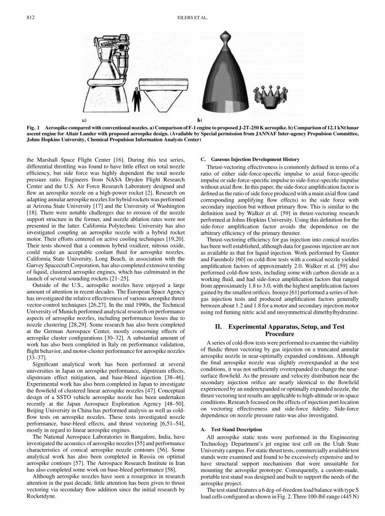
Figure 1 compares two aerospike-based nozzle designs with theirconventional counterparts with the same effective expansion ratios[3]. Figure 1a compares the original Saturn V first-stage F-1A engineto its proposed replacement J-2T-250K aerospike engine (featuring atruncated plug nozzle). It should be noted that both of these enginesare optimized for Earth atmospheric launch conditions. For vacuumconditions, the size difference is greater. This size difference isillustrated by Fig. 1b, where the proposed 12.1 kNt Altair LanderEngine is compared with its aerospike equivalent. In both examples,the size differences are pronounced.
Additionally, one of the often-overlooked properties of the aerospikenozzle is the ability to achieve thrust vectoring aerodynamicallywithoutactive mechanical nozzle gimbals or differential plenum throttling. Thisproperty offers a significant potential for reduced system complexityand weight. With traditional thrust vectoring in conical or bell nozzles,the secondary injection port is far within the nozzle, making thrustvectoring without active primary flow impractical. In contrast toconventional nozzles, thrust vectoringperformedbysecondary injectionon an aerospike nozzle could also be used for attitude controlindependent of main thruster operation. Aerodynamic thrust vectoringon aerospike nozzles offers a potential replacement for both gas attitude-control thrusters and main engine thrust vector gimbal control.
Despite the potential benefits of aerospikenozzles over conventionalnozzle designs, because of a perceived low technology-readiness level,the aerospike configuration has never been deployed on an operationalspacevehicle.One of themajor reasons for this perception is the lackofhigh-quality ground and flight test data and its correlation withanalytical flow predictions. This dearth of data is especially true withregard to off-nominal design performance, thrust vectoring, andthruster-out scenarios for clustered aerospike configurations.
B. Aerospike Nozzle Development History
Significant experimentation on aerospike nozzles was firstcompleted in the 1950s and 1960s when truncated plug nozzles werebeing considered for the Saturn V upper stages [4] and, later, theSpace Shuttle’s main engine [5–7]. During this period, Rocketdyneconducted extensive research into both aerospike performance andliquid injection thrust vectoring [8,9]. Rocketdyne concluded thataerospike nozzles had less or equal thrust vectoring capability thanbell nozzle counterparts. However, their tests were limited to liquidinjection. Rocketdyne did not perform cold-flow thrust-vectoringtests, and hot gas injection hardware was not yet available. After aconventional bell nozzle was chosen for the Space Shuttle mainengine, work on aerospike nozzles reduced significantly until the1990s when work began on the X-33 single stage to orbit (SSTO)vehicle [10]. Supporting this effort, significant testingwas performedbyRocketdyne for Lockheed during the development of theRS-2200linear aerospike [11–13].
After the X-33 and the Venture Star programs were canceled,aerospike nozzle development once again became sporadic. In theU.S.,NASALangleyResearchCenter explored parametricmodelingand optimization of aerospike nozzles [14]. Simultaneously,computational algorithms to evaluate thrust vector control foraerospike nozzles were developed at the University of Alabama inHuntsville [15], and differential throttling research was completed at
Presented as Paper 2011-5531 at the 47th AIAA/ASME/SAE/ASEE JointPropulsion Conference , SanDiego, CA, 28 July–3August 2011; received 30June 2011; revision received 21 November 2011; accepted for publication 9February 2012. Copyright © 2012 by Utah State University. Published by theAmerican Institute of Aeronautics and Astronautics, Inc., with permission.Copies of this paper may be made for personal or internal use, on conditionthat the copier pay the $10.00 per-copy fee to theCopyright Clearance Center,Inc., 222RosewoodDrive, Danvers,MA01923; include the code 0748-4658/12 and $10.00 in correspondence with the CCC.
∗Graduate Research Assistant, Mechanical and Aerospace EngineeringDepartment, 4130 Old Main Hill. Student Member AIAA.
†Associate Professor, Mechanical and Aerospace Engineering Department,4130 Old Main Hill. Associate Fellow AIAA.
JOURNAL OF PROPULSION AND POWER
Vol. 28, No. 4, July–August 2012
811
the Marshall Space Flight Center [16]. During this test series,differential throttling was found to have little effect on total nozzleefficiency, but side force was highly dependent the total nozzlepressure ratio. Engineers from NASA Dryden Flight ResearchCenter and the U.S. Air Force Research Laboratory designed andflew an aerospike nozzle on a high-power rocket [2]. Research onadapting annular aerospike nozzles for hybrid rockets was performedat Arizona State University [17] and the University of Washington[18]. There were notable challenges due to erosion of the nozzlesupport structure in the former, and nozzle ablation rates were notpresented in the latter. California Polytechnic University has alsoinvestigated coupling an aerospike nozzle with a hybrid rocketmotor. Their efforts centered on active cooling techniques [19,20].Their tests showed that a common hybrid oxidizer, nitrous oxide,could make an acceptable coolant fluid for aerospike nozzles.California State University, Long Beach, in association with theGarvey Spacecraft Corporation, has also completed extensive testingof liquid, clustered aerospike engines, which has culminated in thelaunch of several sounding rockets [21–25].
Outside of the U.S., aerospike nozzles have enjoyed a largeamount of attention in recent decades. The European Space Agencyhas investigated the relative effectiveness of various aerospike thrustvector-control techniques [26,27]. In the mid 1990s, the TechnicalUniversity of Munich performed analytical research on performanceaspects of aerospike nozzles, including performance losses due tonozzle clustering [28,29]. Some research has also been completedat the German Aerospace Center, mostly concerning effects ofaerospike cluster configurations [30–32]. A substantial amount ofwork has also been completed in Italy on performance validation,flight behavior, andmotor-cluster performance for aerospike nozzles[33–37].
Significant analytical work has been performed at severaluniversities in Japan on aerospike performance, slipstream effects,slipstream effect mitigation, and base-bleed injection [38–46].Experimental work has also been completed in Japan to investigatethe flowfield of clustered linear aerospike nozzles [47]. Conceptualdesign of a SSTO vehicle aerospike nozzle has been undertakenrecently at the Japan Aerospace Exploration Agency [48–50].Beijing University in China has performed analysis as well as cold-flow tests on aerospike nozzles. These tests investigated nozzleperformance, base-bleed effects, and thrust vectoring [6,51–54],mostly in regard to linear aerospike engines.
The National Aerospace Laboratories in Bangalore, India, haveinvestigated the acoustics of aerospike nozzles [55] and performancecharacteristics of conical aerospike nozzle contours [56]. Someanalytical work has also been completed in Russia on optimalaerospike contours [57]. The Aerospace Research Institute in Iranhas also completed some work on base-bleed performance [58].
Although aerospike nozzles have seen a resurgence in researchattention in the past decade, little attention has been given to thrustvectoring via secondary flow addition since the initial research byRocketdyne.
C. Gaseous Injection Development History
Thrust-vectoring effectiveness is commonly defined in terms of aratio of either side-force-specific impulse to axial force-specificimpulse or side-force-specific impulse to side-force-specific impulsewithout axial flow. In this paper, the side-force amplification factor isdefined as the ratio of side force producedwith amain axial flow (andcorresponding amplifying flow effects) to the side force withsecondary injection but without primary flow. This is similar to thedefinition used by Walker et al. [59] in thrust-vectoring researchperformed at Johns Hopkins University. Using this definition for theside-force amplification factor avoids the dependence on thearbitrary efficiency of the primary thruster.
Thrust-vectoring efficiency for gas injection into conical nozzleshas been well established, although data for gaseous injection are notas available as that for liquid injection. Work performed by Gunterand Farenholz [60] on cold-flow tests with a conical nozzle yieldedamplification factors of approximately 2.0. Walker et al. [59] alsoperformed cold-flow tests, including some with carbon dioxide as aworking fluid, and had side-force amplification factors that rangedfrom approximately 1.8 to 3.0, with the highest amplification factorsgained by the smallest orifices. Inouye [61] performed a series of hot-gas injection tests and produced amplification factors generallybetween about 1.2 and 1.8 for a motor and secondary injection motorusing red fuming nitric acid and unsymmetrical dimethylhydrazine.
II. Experimental Apparatus, Setup, and TestProcedure
A series of cold-flow tests were performed to examine the viabilityof fluidic thrust vectoring by gas injection on a truncated annularaerospike nozzle in near-optimally expanded conditions. Althoughthe final aerospike nozzle was slightly overexpanded at the testconditions, it was not sufficiently overexpanded to change the near-surface flowfield. As the pressure and velocity distribution near thesecondary injection orifice are nearly identical to the flowfieldexperienced by an underexpanded or optimally expanded nozzle, thethrust vectoring test results are applicable to high-altitude or in-spaceconditions. Research focused on the effects of injection port locationon vectoring effectiveness and side-force fidelity. Side-forcedependence on nozzle pressure ratio was also investigated.
A. Test Stand Description
All aerospike static tests were performed in the EngineeringTechnology Department’s jet engine test cell on the Utah StateUniversity campus. For static thrust tests, commercially available teststands were examined and found to be excessively expensive and tohave structural support mechanisms that were unsuitable formounting the aerospike prototype. Consequently, a custom-made,portable test stand was designed and built to support the needs of theaerospike project.
The test stand features a 6 deg-of-freedom load balancewith type Sload cells configured as shown in Fig. 2. Three 100-lbf-range (445N)
Fig. 1 Aerospike comparedwith conventional nozzles. a) Comparison of F-1 engine to proposed J-2T-250Kaerospike. b)Comparison of 12.1 kNt lunar
ascent engine for Altair Lander with proposed aerospike design. (Available by Special permission from JANNAF Inter-agency Propulsion Committee,Johns Hopkins University, Chemical Propulsion Information Analysis Center)
812 EILERS ETAL.

axial and three 25-lbf-range (111 N) lateral load cells are arrangedsuch that 6-deg-of-freedom force and moment measurements can beresolved. The thrust stand is designed so that the nozzle exhaustplume exits vertically, and the thrust acts downward onto the test cart.The thrust stand coordinate system, also pictured in Fig. 2, is definedwith the x axis aligned vertically upward along the axial centerline ofthe nozzle. The test standwas calibrated in situwith a simultaneouslymulti-axial calibration method. The total resultant uncertainty(to 95% confidence) for forces using this calibration method wasstatistically determined as approximately 0.25 N for side forces and1.75 N for axial loading with nominal values of 15 N andapproximately 400 N, respectively [62].
For ease of storage and handling, carbon dioxide was chosen for aworking fluid. Figure 3 presents a plumbing and instrumentationdiagram of the associated cold-gas feed system. Saturated liquidcarbon dioxide is stored in standard K-sized storage tanks, with eachtank having a storage capacity of approximately 25 kg. Multipletanks were manifolded to ensure that the required mass flow levelsand run times can be achieved. Flow out of the tanks is controlled viaa pneumatic ball valve. The pneumatic valve actuator is controlledwith a 12 V direct current solenoid valve. Beyond the ball valve,carbon dioxide flows through a manually set needle valve that dropsthe pressure from the saturation pressure of carbon dioxide, 4825–5515 kPa (700–800 psia) at room temperature, to approximately1035 kPa (150 psi). Carbon dioxide then flows into a water-bath heatexchanger, which raises the temperature of the expanded carbondioxide by approximately 25�C. The pressure downstream of theneedle valve is controlled using a backflow pressure regulator and aprimary regulator in parallel. The needle valve and the backflowregulatormaintain approximately 1034 kPa (150 psi) upstream of theprimary regulator. The primary flow regulator further drops the feedpressure to approximately 690 kPa (100 psi) at the plenum inlet.
At full pressure, the primary regulator is set to allow approximately1 kg/s mass flow through the aerospike nozzle throat. The backpressureregulator will vent approximately half that flow rate at startup. As thetanks evacuate and the overall system pressure drops, flow through thebackpressure regulator diminishes to zero. An additional electronicregulator in parallel with the main flow regulator controls the upstreampressure of the secondary (thrust vectoring and base-bleed) flowinjection ports.
Type-K thermocouples andpressure transducers are used tomonitortemperatures and pressures throughout the flow system. A custom-manufactured Venturi flow meter, also using pressure transducers tomeasure the pressure differential, is situated upstreamof the electronicregulator. Although a differential pressure transducerwas not used, thepressure transducer voltage bias is removed at full operating pressurewhen the secondary flow injection is turned fully off. This results in adifferential pressure measurement accurate to within about 0.1% ofdifferential reading. The Venturi was calibrated in situ using high flowcoefficient sonic orifices. In this manner, the flow coefficient for theVenturi was calculated to be 0.980, which is very near the expectedresult forVenturiflowmeters of this design. The typicalmassflow rateuncertainty with this Venturi was about 1.0% of the measurement.
B. Test Article Description
Because of manufacturing considerations (high expansion ratiosyield larger aerospike nozzles, which are easier to manufacture), theaerospike nozzle used for cold-flow experimentation is sized to beslightly overexpanded for operating conditions at the test altitude,1450 m (about 86.2 kPa), in Logan, Utah. The resulting expansionratio is 2.47. It is desirable to keep the near-surface flowfield close towhatwould be experienced in in-space or underexpanded conditions.To accomplish this, the aerospike was designed using a method ofcharacteristics code to verify that compression waves generated byoverexpansion would not intersect the end of the truncated spike atfull chamber pressure. The resulting plug was truncated such that thetest article was 57% of the length of a full spike. This design resultsin an aerospike pressure distribution roughly independent ofatmospheric pressure, except for the base area and the very endof the spike length. This effect was confirmed through the use ofcomputational fluid dynamics. The salient aerospike characteristicsare shown in Table 1, and the aerospike and plenum geometries areshown in Figs. 4 and 5.
III. Experimental Results
Aerospike nozzle configurations with secondary injection portslocated at 20, 80, and 90% axial position along the truncated spikewere tested with secondary mass flow rates between 0.005 and0:016 kg=s and primary mass flow rates between 0.70 and0:95 kg=s. These flow rates correspond to secondary flow inlet
Fig. 2 6-deg-of-freedom test stand.
Fig. 3 Aerospike propellant feed system.
EILERS ETAL. 813

pressures between approximately 400 and 800 kPa and primaryplenum pressures between about 350 and 600 kPa. The secondaryinjection orifices were machined such that they injected fluid normalto the aerospike’s longitudinal axis. These port locations are shown inFig. 4. Lateral force, secondary injection pressure, mass flow rate,and temperatures for two typical tests are shown in Fig. 6. The sideforce, specific impulse, and secondary flow pressure for the 90%secondary injection location for both main flow on andmain flow offis shown in Fig. 7. The response fidelity between the electronicregulator control and the output size force is clearly shown in both ofthese figures. A high degree of repeatability and crisp thrustvectoring response was typical of the entire test series.
The resulting side-force amplification factor and specific impulsefor each configuration is shown in Table 2 and Fig. 8. An additionalconfiguration with a larger-diameter injection orifice and atapproximately 90% the length of the truncated spike was also testedto examine side-force scaling. These results are shown in Fig. 9.
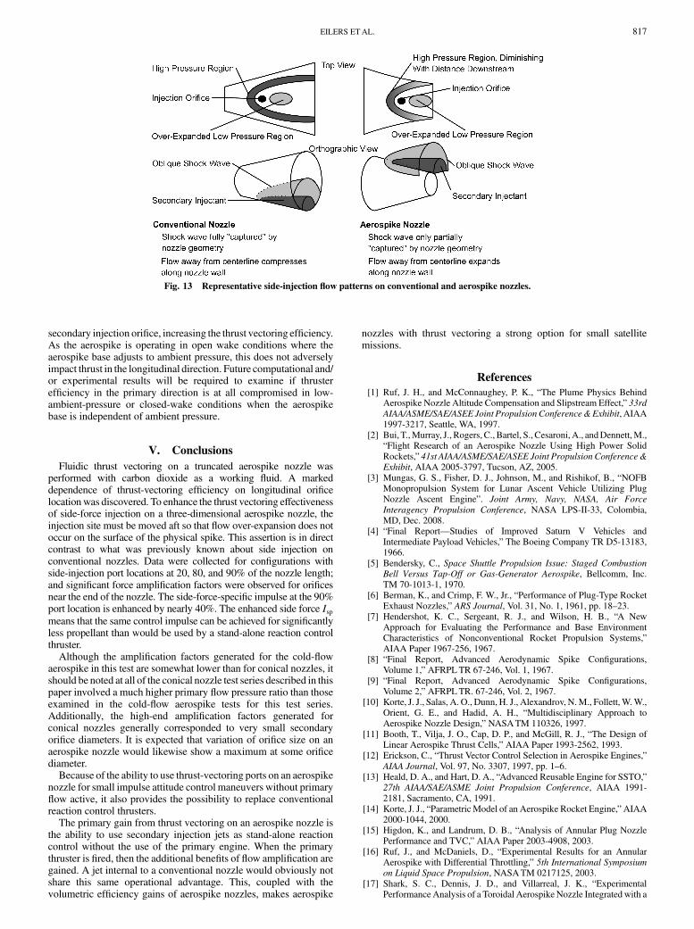
The use of carbon dioxide as a operatingfluid allowed for excellenttest flow visualization when the fluid crystallizes near the end of theaerospike contour. This phase change creates a semi-opaque cloud
that is readily visible. The temperature increase caused by shockwaves resulting from secondary fluid injection creates clear areas inthe flowfield that are easily distinguishable. The leading edge bowshock caused by fluid injection for a high flow rate test is clearly seenin Fig. 10.
During the cold-flow test series, the ratio of the chamber pressure toambient pressure was varied from approximately 5.0 to 8.0. Nomeaningful correlation between side-force-specific impulse andchamber pressure was observed over this range. The side force Isp forthis range with the 90% injection orifice location is shown in Fig. 11.Near the upper part of this range, the nozzle surface pressure iseffectively independent of ambient pressure. At lower pressure ratios,aerospike altitude compensation influences local ambient Machnumber and density around the secondary flow orifice. It is probablethat the variation of these two parameters has counterbalancinginfluences on the side-force-specific impulse over the rangeof pressureratios examined during cold-flow testing.
It is notable that the secondary injectant does not reach sonicvelocity at the immediate exit of the injection orifice. The bow shockcaused by primary flow results in an effectively reduced orifice exitarea for the injectant immediately downstream of the orifice.This reduced area results in a drop in discharge coefficient ofapproximately 5% between tests with secondary injection only andsecondary injection with active primary flow.
For aerospike configurations with the secondary injection pointnear the end of the aerospike, the effect of secondary fluid injectionon axial thrust was small enough such that it was not detectable by thecurrent testing apparatus. The maximum side force for the largerorifice is approximately 14 N. For these tests, the average primarythrust level is 343 N. This results in a total thrust vector deflection ofabout 2.3 deg or a side-force level of 4.1%. Resultant cosine lossesfor this thrust angle are therefore less than 0.1%, so it is not surprisingthat no net effect on axial thrust is detected at these side-force levels.Similarly, maximum side-force levels for the smaller, more efficientorifice sizewere about 8 N. This yields a net side-force level of about2.3% or about 1.3 deg. Cosine losses for this configuration would beon the order of 0.03%.
IV. Effect of Longitudinal Injection Location
The test series showed a marked dependence for side-forceamplification factor on longitudinal hole location. Over the range oflocations examined in this test series, the optimal injection locationwas at the aft edge of the truncated aerospike length. This is clearlyshown in Fig. 12. This trend is in direct contradiction to side-forcerelations historically obtained on conical nozzles. For lab scale testson conical nozzles, the optimum injection point for gas injection hasbeen found to be nearest the throat where the resulting bow shockdoes not impinge on the opposite nozzle wall [60]. Two explanationsfor this optimal port location are diminishing the effect of the lowpressure, overexpanded region directly downstream of the injectionlocation and the effect of local primary flow Mach number at theinjection location.
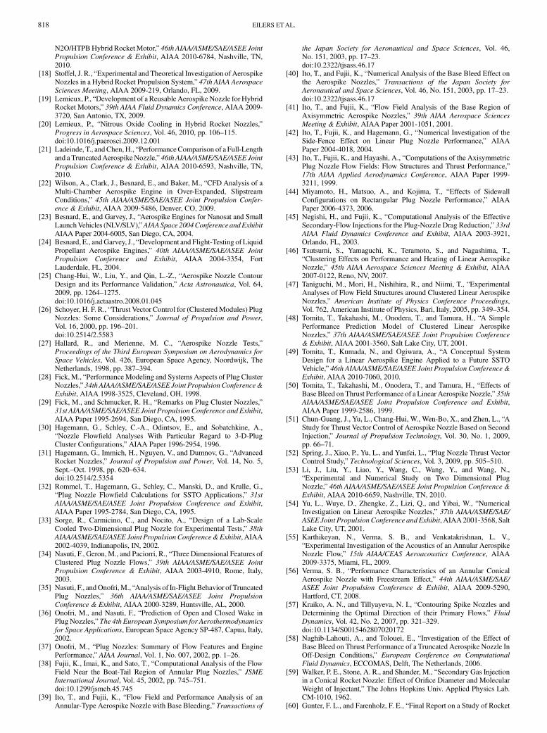
The mechanism for side-force generation by secondary injectionon an aerospike nozzle differs significantly from those generated byside injection on a conventional nozzle. Figure 13 compares the side-injection flow patterns on conventional and aerospike nozzles. Inboth cases, the injected flow produces a strong shock wave and asignificant proverse pressure increase behind the shockwave. In bothcases, there is also a low-pressure region caused by overexpansion ofthe secondary injectant into the primaryflowfield. Theseflow regionshave been amply studied during secondary injection experimentscompleted onflat plates [63,64]. In a conventional nozzle, theflowaftof this injection point follows a concave path away from thecenterline. This limits the deterioration of the high-pressure regioncaused by the shock wave as the entire shock wave is captured by thenozzle geometry. Thus, the effects of the leading shock wave and thelow pressure region due to overexpansion tend to cancel out in a bellnozzle [65,66].
On an aerospike nozzle, however, the flow behind the injectionpoint follows a convexpath. Directly downstreamof the injection site
Table 1 Cold-flow aerospike parameters
Aerospike Parameter Value
Plug diameter 3.2 cmOuter throat diameter 3.86 cmTruncated length 2.54 cmFull isentropic spike length 4.31 cmTruncation ratio 57%Throat diameter 0.29 cmOperating stagnation pressure 775 kPaNozzle expansion ratio 2.47Plenum exit throat area 4:73 cm3
Secondary injection port diameter 0.3175 cmDesign altitude 4206 m MSLDesign thrust 454 NDesign mass flow rate 1:0 kg=s
Fig. 4 Cold-flow aerospike test configuration.
0 0.005 0.01 0.015 0.020
0.005
0.01
0.015
0.02
Aerospike axis, m
Aer
ospi
ke r
adiu
s, m
Spike Profile
Throat
Fig. 5 Cold-flow aerospike profile.
814 EILERS ETAL.

there occurs a predicted drop in Mach number and a correspondingpressure increase. Because of the convex aerospike nozzle shape, thesecondary injection disturbance propagates across the entire upperspike surface downstream of the injection site, and the convexsurface contour results in a flow expansion on the injectant side of the
nozzle. When the injection occurs on the upstream portions of thenozzle, the resulting expansion region offsets any gain achieved bythe high-pressure compression behind the shockwave. The net resultis a total side force that is less than what would be produced by theinjected pulse alone.
5 10 15 20 25 300
5
10
a) Secondary Injection Lateral ForceTime, s
Late
ral f
orce
, N
5 10 15 20 25 300
200
400
600
800
b) Secondary Injection PressureTime, s
Gau
ge p
ress
ure,
kP
a
5 10 15 20 25 300
20
40
c) Secondary Injection Flow TemperatureTime, s
Tem
pera
ture
, °C
5 10 15 20 25 300
0.005
0.01
0.015
0.02
d) Secondary Injection Mass FlowTime, s
Mas
s flo
w, k
g/s
Test 5
Test 6
Fig. 6 Side force and secondary injection pressure for 90% injection point.
5 10 15 20 25 300
5
10
a) Secondary Injection Lateral Force
Time, s
Late
ral f
orce
, N
5 10 15 20 25 300
200
400
600
800
b) Secondary Injection Pressure
Time, s
Gau
ge p
ress
ure,
kP
a
5 10 15 20 25 300
20
40
60
c) Secondary I sp
Time, s
I sp,
s
Test 5 Secondary Flow
Test 5 Primary Flow
Secondary Flow Only
Fig. 7 Side force and secondary injection for 90% injection point for both primary-flow-only and secondary-flow-only configurations.
Table 2 Cold-flow test specific-impulse results
Test series Isp, s Isp uncertainty, s, 95% Amplification factor
Injection location at 90% 54.8 �1:9 1.39Injection location at 80% 47.0 �1:9 1.19Injection location at 20% 21.2 �1:7 0.54Secondary flow only 39.5 �1:8
EILERS ETAL. 815
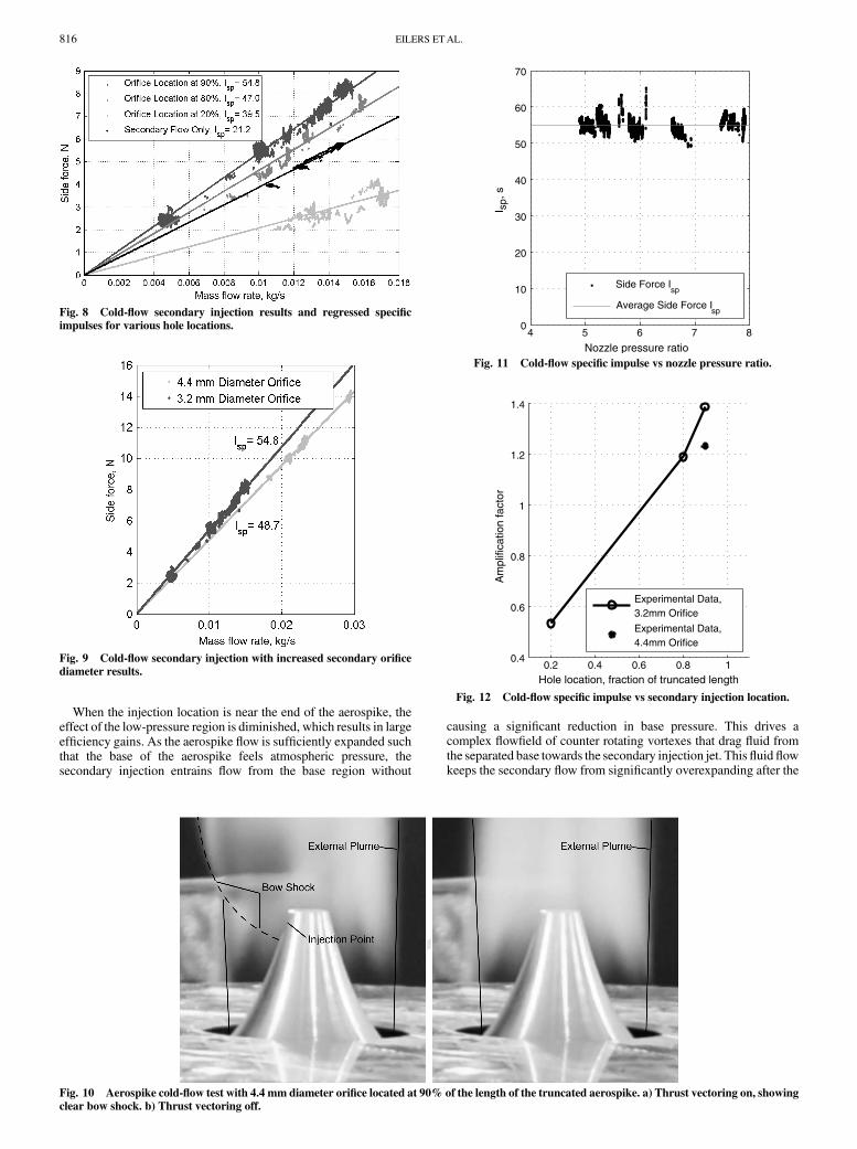
When the injection location is near the end of the aerospike, theeffect of the low-pressure region is diminished, which results in largeefficiency gains. As the aerospike flow is sufficiently expanded suchthat the base of the aerospike feels atmospheric pressure, thesecondary injection entrains flow from the base region without
causing a significant reduction in base pressure. This drives acomplex flowfield of counter rotating vortexes that drag fluid fromthe separated base towards the secondary injection jet. Thisfluid flowkeeps the secondary flow from significantly overexpanding after the
Fig. 8 Cold-flow secondary injection results and regressed specific
impulses for various hole locations.
Fig. 9 Cold-flow secondary injection with increased secondary orifice
diameter results.
Fig. 10 Aerospike cold-flow test with 4.4 mm diameter orifice located at 90% of the length of the truncated aerospike. a) Thrust vectoring on, showing
clear bow shock. b) Thrust vectoring off.
4 5 6 7 80
10
20
30
40
50
60
70
Nozzle pressure ratio
I sp,
s
Side Force Isp
Average Side Force Isp
Fig. 11 Cold-flow specific impulse vs nozzle pressure ratio.
0.2 0.4 0.6 0.8 10.4
0.6
0.8
1
1.2
1.4
Hole location, fraction of truncated length
Am
plifi
catio
n fa
ctor
Experimental Data,3.2mm Orifice
Experimental Data,4.4mm Orifice
Fig. 12 Cold-flow specific impulse vs secondary injection location.
816 EILERS ETAL.
secondary injection orifice, increasing the thrust vectoring efficiency.As the aerospike is operating in open wake conditions where theaerospike base adjusts to ambient pressure, this does not adverselyimpact thrust in the longitudinal direction. Future computational and/or experimental results will be required to examine if thrusterefficiency in the primary direction is at all compromised in low-ambient-pressure or closed-wake conditions when the aerospikebase is independent of ambient pressure.
V. Conclusions
Fluidic thrust vectoring on a truncated aerospike nozzle wasperformed with carbon dioxide as a working fluid. A markeddependence of thrust-vectoring efficiency on longitudinal orificelocationwas discovered. To enhance the thrust vectoring effectivenessof side-force injection on a three-dimensional aerospike nozzle, theinjection site must be moved aft so that flow over-expansion does notoccur on the surface of the physical spike. This assertion is in directcontrast to what was previously known about side injection onconventional nozzles. Data were collected for configurations withside-injection port locations at 20, 80, and 90% of the nozzle length;and significant force amplification factors were observed for orificesnear the end of the nozzle. The side-force-specific impulse at the 90%port location is enhanced by nearly 40%. The enhanced side force Ispmeans that the same control impulse can be achieved for significantlyless propellant than would be used by a stand-alone reaction controlthruster.
Although the amplification factors generated for the cold-flowaerospike in this test are somewhat lower than for conical nozzles, itshould be noted at all of the conical nozzle test series described in thispaper involved a much higher primary flow pressure ratio than thoseexamined in the cold-flow aerospike tests for this test series.Additionally, the high-end amplification factors generated forconical nozzles generally corresponded to very small secondaryorifice diameters. It is expected that variation of orifice size on anaerospike nozzle would likewise show a maximum at some orificediameter.
Because of the ability to use thrust-vectoring ports on an aerospikenozzle for small impulse attitude control maneuvers without primaryflow active, it also provides the possibility to replace conventionalreaction control thrusters.
The primary gain from thrust vectoring on an aerospike nozzle isthe ability to use secondary injection jets as stand-alone reactioncontrol without the use of the primary engine. When the primarythruster is fired, then the additional benefits of flow amplification aregained. A jet internal to a conventional nozzle would obviously notshare this same operational advantage. This, coupled with thevolumetric efficiency gains of aerospike nozzles, makes aerospike
nozzles with thrust vectoring a strong option for small satellitemissions.
References
[1] Ruf, J. H., and McConnaughey, P. K., “The Plume Physics BehindAerospike Nozzle Altitude Compensation and Slipstream Effect,” 33rdAIAA/ASME/SAE/ASEE Joint PropulsionConference&Exhibit, AIAA1997-3217, Seattle, WA, 1997.
[2] Bui, T.,Murray, J., Rogers, C., Bartel, S., Cesaroni, A., andDennett,M.,“Flight Research of an Aerospike Nozzle Using High Power SolidRockets,” 41st AIAA/ASME/SAE/ASEE Joint Propulsion Conference&
Exhibit, AIAA 2005-3797, Tucson, AZ, 2005.[3] Mungas, G. S., Fisher, D. J., Johnson, M., and Rishikof, B., “NOFB
Monopropulsion System for Lunar Ascent Vehicle Utilizing PlugNozzle Ascent Engine”. Joint Army, Navy, NASA, Air Force
Interagency Propulsion Conference, NASA LPS-II-33, Colombia,MD, Dec. 2008.
[4] “Final Report—Studies of Improved Saturn V Vehicles andIntermediate Payload Vehicles,” The Boeing Company TR D5-13183,1966.
[5] Bendersky, C., Space Shuttle Propulsion Issue: Staged Combustion
Bell Versus Tap-Off or Gas-Generator Aerospike, Bellcomm, Inc.TM 70-1013-1, 1970.
[6] Berman, K., and Crimp, F. W., Jr., “Performance of Plug-Type RocketExhaust Nozzles,” ARS Journal, Vol. 31, No. 1, 1961, pp. 18–23.
[7] Hendershot, K. C., Sergeant, R. J., and Wilson, H. B., “A NewApproach for Evaluating the Performance and Base EnvironmentCharacteristics of Nonconventional Rocket Propulsion Systems,”AIAA Paper 1967-256, 1967.
[8] “Final Report, Advanced Aerodynamic Spike Configurations,Volume 1,” AFRPLTR 67-246, Vol. 1, 1967.
[9] “Final Report, Advanced Aerodynamic Spike Configurations,Volume 2,” AFRPLTR. 67-246, Vol. 2, 1967.
[10] Korte, J. J., Salas, A. O., Dunn, H. J., Alexandrov, N.M., Follett,W.W.,Orient, G. E., and Hadid, A. H., “Multidisciplinary Approach toAerospike Nozzle Design,” NASATM 110326, 1997.
[11] Booth, T., Vilja, J. O., Cap, D. P., and McGill, R. J., “The Design ofLinear Aerospike Thrust Cells,” AIAA Paper 1993-2562, 1993.
[12] Erickson, C., “Thrust Vector Control Selection in Aerospike Engines,”AIAA Journal, Vol. 97, No. 3307, 1997, pp. 1–6.
[13] Heald, D. A., and Hart, D. A., “Advanced Reusable Engine for SSTO,”27th AIAA/SAE/ASME Joint Propulsion Conference, AIAA 1991-2181, Sacramento, CA, 1991.
[14] Korte, J. J., “Parametric Model of an Aerospike Rocket Engine,”AIAA2000-1044, 2000.
[15] Higdon, K., and Landrum, D. B., “Analysis of Annular Plug NozzlePerformance and TVC,” AIAA Paper 2003-4908, 2003.
[16] Ruf, J., and McDaniels, D., “Experimental Results for an AnnularAerospike with Differential Throttling,” 5th International Symposium
on Liquid Space Propulsion, NASATM 0217125, 2003.[17] Shark, S. C., Dennis, J. D., and Villarreal, J. K., “Experimental
Performance Analysis of a Toroidal Aerospike Nozzle Integrated with a
Fig. 13 Representative side-injection flow patterns on conventional and aerospike nozzles.
EILERS ETAL. 817
N2O/HTPBHybrid RocketMotor,” 46th AIAA/ASME/SAE/ASEE Joint
Propulsion Conference & Exhibit, AIAA 2010-6784, Nashville, TN,2010.
[18] Stoffel, J. R., “Experimental and Theoretical Investigation of AerospikeNozzles in a Hybrid Rocket Propulsion System,” 47th AIAA Aerospace
Sciences Meeting, AIAA 2009-219, Orlando, FL, 2009.[19] Lemieux, P., “Development of a Reusable Aerospike Nozzle for Hybrid
Rocket Motors,” 39th AIAA Fluid Dynamics Conference, AIAA 2009-3720, San Antonio, TX, 2009.
[20] Lemieux, P., “Nitrous Oxide Cooling in Hybrid Rocket Nozzles,”Progress in Aerospace Sciences, Vol. 46, 2010, pp. 106–115.doi:10.1016/j.paerosci.2009.12.001
[21] Ladeinde, T., andChen,H., “PerformanceComparison of a Full-Lengthand a TruncatedAerospikeNozzle,” 46th AIAA/ASME/SAE/ASEE Joint
Propulsion Conference & Exhibit, AIAA 2010-6593, Nashville, TN,2010.
[22] Wilson, A., Clark, J., Besnard, E., and Baker, M., “CFD Analysis of aMulti-Chamber Aerospike Engine in Over-Expanded, SlipstreamConditions,” 45th AIAA/ASME/SAE/ASEE Joint Propulsion Confer-
ence & Exhibit, AIAA 2009-5486, Denver, CO, 2009.[23] Besnard, E., and Garvey, J., “Aerospike Engines for Nanosat and Small
LaunchVehicles (NLV/SLV),”AIAASpace 2004ConferenceandExhibitAIAA Paper 2004-6005, San Diego, CA, 2004.
[24] Besnard, E., andGarvey, J., “Development and Flight-Testing of LiquidPropellant Aerospike Engines,” 40th AIAA/ASME/SAE/ASEE Joint
Propulsion Conference and Exhibit, AIAA 2004-3354, FortLauderdale, FL, 2004.
[25] Chang-Hui, W., Liu, Y., and Qin, L.-Z., “Aerospike Nozzle ContourDesign and its Performance Validation,” Acta Astronautica, Vol. 64,2009, pp. 1264–1275.doi:10.1016/j.actaastro.2008.01.045
[26] Schoyer, H. F. R., “Thrust Vector Control for (ClusteredModules) PlugNozzles: Some Considerations,” Journal of Propulsion and Power,Vol. 16, 2000, pp. 196–201.doi:10.2514/2.5583
[27] Hallard, R., and Merienne, M. C., “Aerospike Nozzle Tests,”Proceedings of the Third European Symposium on Aerodynamics for
Space Vehicles, Vol. 426, European Space Agency, Noordwijk, TheNetherlands, 1998, pp. 387–394.
[28] Fick,M., “PerformanceModeling and Systems Aspects of Plug ClusterNozzles,” 34thAIAA/ASME/SAE/ASEE Joint PropulsionConference&
Exhibit, AIAA 1998-3525, Cleveland, OH, 1998.[29] Fick, M., and Schmucker, R. H., “Remarks on Plug Cluster Nozzles,”
31st AIAA/ASME/SAE/ASEE Joint Propulsion Conference and Exhibit,AIAA Paper 1995-2694, San Diego, CA, 1995.
[30] Hagemann, G., Schley, C.-A., Odintsov, E., and Sobatchkine, A.,“Nozzle Flowfield Analyses With Particular Regard to 3-D-PlugCluster Configurations,” AIAA Paper 1996-2954, 1996.
[31] Hagemann, G., Immich, H., Nguyen, V., and Dumnov, G., “AdvancedRocket Nozzles,” Journal of Propulsion and Power, Vol. 14, No. 5,Sept.–Oct. 1998, pp. 620–634.doi:10.2514/2.5354
[32] Rommel, T., Hagemann, G., Schley, C., Manski, D., and Krulle, G.,“Plug Nozzle Flowfield Calculations for SSTO Applications,” 31st
AIAA/ASME/SAE/ASEE Joint Propulsion Conference and Exhibit,AIAA Paper 1995-2784, San Diego, CA, 1995.
[33] Sorge, R., Carmicino, C., and Nocito, A., “Design of a Lab-ScaleCooled Two-Dimensional Plug Nozzle for Experimental Tests,” 38th
AIAA/ASME/SAE/ASEE Joint PropulsionConference&Exhibit, AIAA2002-4039, Indianapolis, IN, 2002.
[34] Nasuti, F., Geron, M., and Paciorri, R., “Three Dimensional Features ofClustered Plug Nozzle Flows,” 39th AIAA/ASME/SAE/ASEE Joint
Propulsion Conference & Exhibit, AIAA 2003-4910, Rome, Italy,2003.
[35] Nasuti, F., andOnofri,M., “Analysis of In-Flight Behavior of TruncatedPlug Nozzles,” 36th AIAA/ASME/SAE/ASEE Joint Propulsion
Conference & Exhibit, AIAA 2000-3289, Huntsville, AL, 2000.[36] Onofri, M., and Nasuti, F., “Prediction of Open and Closed Wake in
PlugNozzles,” The 4th European Symposium for Aerothermodynamics
for Space Applications, European Space Agency SP-487, Capua, Italy,2002.
[37] Onofri, M., “Plug Nozzles: Summary of Flow Features and EnginePerformance,” AIAA Journal, Vol. 1, No. 007, 2002, pp. 1–26.
[38] Fujii, K., Imai, K., and Sato, T., “Computational Analysis of the FlowField Near the Boat-Tail Region of Annular Plug Nozzles,” JSME
International Journal, Vol. 45, 2002, pp. 745–751.doi:10.1299/jsmeb.45.745
[39] Ito, T., and Fujii, K., “Flow Field and Performance Analysis of anAnnular-Type Aerospike Nozzle with Base Bleeding,” Transactions of
the Japan Society for Aeronautical and Space Sciences, Vol. 46,No. 151, 2003, pp. 17–23.doi:10.2322/tjsass.46.17
[40] Ito, T., and Fujii, K., “Numerical Analysis of the Base Bleed Effect onthe Aerospike Nozzles,” Transactions of the Japan Society for
Aeronautical and Space Sciences, Vol. 46, No. 151, 2003, pp. 17–23.doi:10.2322/tjsass.46.17
[41] Ito, T., and Fujii, K., “Flow Field Analysis of the Base Region ofAxisymmetric Aerospike Nozzles,” 39th AIAA Aerospace Sciences
Meeting & Exhibit, AIAA Paper 2001-1051, 2001.[42] Ito, T., Fujii, K., and Hagemann, G., “Numerical Investigation of the
Side-Fence Effect on Linear Plug Nozzle Performance,” AIAAPaper 2004-4018, 2004.
[43] Ito, T., Fujii, K., and Hayashi, A., “Computations of the AxisymmetricPlug Nozzle Flow Fields: Flow Structures and Thrust Performance,”17th AIAA Applied Aerodynamics Conference, AIAA Paper 1999-3211, 1999.
[44] Miyamoto, H., Matsuo, A., and Kojima, T., “Effects of SidewallConfigurations on Rectangular Plug Nozzle Performance,” AIAAPaper 2006-4373, 2006.
[45] Negishi, H., and Fujii, K., “Computational Analysis of the EffectiveSecondary-Flow Injections for the Plug-Nozzle Drag Reduction,” 33rdAIAA Fluid Dynamics Conference and Exhibit, AIAA 2003-3921,Orlando, FL, 2003.
[46] Tsutsumi, S., Yamaguchi, K., Teramoto, S., and Nagashima, T.,“Clustering Effects on Performance and Heating of Linear AerospikeNozzle,” 45th AIAA Aerospace Sciences Meeting & Exhibit, AIAA2007-0122, Reno, NV, 2007.
[47] Taniguchi, M., Mori, H., Nishihira, R., and Niimi, T., “ExperimentalAnalyses of Flow Field Structures around Clustered Linear AerospikeNozzles,” American Institute of Physics Conference Proceedings,Vol. 762, American Institute of Physics, Bari, Italy, 2005, pp. 349–354.
[48] Tomita, T., Takahashi, M., Onodera, T., and Tamura, H., “A SimplePerformance Prediction Model of Clustered Linear AerospikeNozzles,” 37th AIAA/ASME/SAE/ASEE Joint Propulsion Conference
& Exhibit, AIAA 2001-3560, Salt Lake City, UT, 2001.[49] Tomita, T., Kumada, N., and Ogiwara, A., “A Conceptual System
Design for a Linear Aerospike Engine Applied to a Future SSTOVehicle,” 46th AIAA/ASME/SAE/ASEE Joint Propulsion Conference &
Exhibit, AIAA 2010-7060, 2010.[50] Tomita, T., Takahashi, M., Onodera, T., and Tamura, H., “Effects of
Base Bleed on Thrust Performance of a Linear Aerospike Nozzle,” 35thAIAA/ASME/SAE/ASEE Joint Propulsion Conference and Exhibit,AIAA Paper 1999-2586, 1999.
[51] Chun-Guang, J., Yu, L., Chang-Hui, W., Wen-Bo, X., and Zhen, L., “AStudy for Thrust Vector Control of Aerospike Nozzle Based on SecondInjection,” Journal of Propulsion Technology, Vol. 30, No. 1, 2009,pp. 66–71.
[52] Spring, J., Xiao, P., Yu, L., and Yunfei, L., “Plug Nozzle Thrust VectorControl Study,” Technological Sciences, Vol. 3, 2009, pp. 505–510.
[53] Li, J., Liu, Y., Liao, Y., Wang, C., Wang, Y., and Wang, N.,“Experimental and Numerical Study on Two Dimensional PlugNozzle,” 46th AIAA/ASME/SAE/ASEE Joint Propulsion Conference &
Exhibit, AIAA 2010-6659, Nashville, TN, 2010.[54] Yu, L., Wuye, D., Zhengke, Z., Lizi, Q., and Yibai, W., “Numerical
Investigation on Linear Aerospike Nozzles,” 37th AIAA/ASME/SAE/
ASEE Joint PropulsionConference andExhibit, AIAA2001-3568, SaltLake City, UT, 2001.
[55] Karthikeyan, N., Verma, S. B., and Venkatakrishnan, L. V.,“Experimental Investigation of the Acoustics of an Annular AerospikeNozzle Flow,” 15th AIAA/CEAS Aeroacoustics Conference, AIAA2009-3375, Miami, FL, 2009.
[56] Verma, S. B., “Performance Characteristics of an Annular ConicalAerospike Nozzle with Freestream Effect,” 44th AIAA/ASME/SAE/
ASEE Joint Propulsion Conference & Exhibit, AIAA 2009-5290,Hartford, CT, 2008.
[57] Kraiko, A. N., and Tillyayeva, N. I., “Contouring Spike Nozzles andDetermining the Optimal Direction of their Primary Flows,” Fluid
Dynamics, Vol. 42, No. 2, 2007, pp. 321–329.doi:10.1134/S0015462807020172
[58] Naghib-Lahouti, A., and Tolouei, E., “Investigation of the Effect ofBase Bleed on Thrust Performance of a Truncated Aerospike Nozzle InOff-Design Conditions,” European Conference on Computational
Fluid Dynamics, ECCOMAS, Delft, The Netherlands, 2006.[59] Walker, P. E., Stone, A. R., and Shander, M., “Secondary Gas Injection
in a Conical Rocket Nozzle: Effect of Orifice Diameter and MolecularWeight of Injectant,” The Johns Hopkins Univ. Applied Physics Lab.CM-1010, 1962.
[60] Gunter, F. L., and Farenholz, F. E., “Final Report on a Study of Rocket
818 EILERS ETAL.

Thrust Control by Gas Injection,” Massachusetts Inst. of TechnologyNaval Supersonic Laboratory TR 448, 1961.
[61] Inoyue, T., “Experiments on Rocket Thrust Vector Control by Hot GasInjection,” Journal of Spacecraft and Rockets, Vol. 3, No. 5, 1966,pp. 737–739.doi:10.2514/3.28522
[62] Eilers, S. D., Wilson, M. D., and Whitmore, S. A., “Analytical andExperiment Evaluation of Aerodymamic Thrust Vectoring on anAerospike Nozzle,” 46th AIAA/ASME/SAE/ASEE Joint Propulsion
Conference & Exhibit, AIAA 2010-6964, 2010.[63] Zukoski, E. E., and Spaid, F. W., “Secondary Injection of Gases into a
Supersonic Flow,” AIAA Journal, Vol. 2, No. 10, 1964, pp. 1689–1697.
doi:10.2514/3.2653[64] Guhse, R. D., “On Secondary Gas Injection in Supersonic Nozzles,”
Journal of Spacecraft and Rockets, Vol. 3, No. 1, 1966, pp. 143–149.[65] Wu, J.-M., Chapkins, R. L., and Mager, A., “Approximate Analyses of
ThrustVector Control by Fluid Injection,”ARS Journal, Vol. 31,No. 12,1961, pp. 1677–1684.
[66] Besnard, E., Chen, H. H., and Mueller, T., “Design, Manufacturing andTest of a Plug Nozzle Rocket Engine,” AIAA Paper 2002-4038, 2002.
C. SegalAssociate Editor
EILERS ETAL. 819