SHRIMP: A ROVER ARCHITECTURE FOR LONG RANGE MARTIAN...
7
Keywords : locomotion, roving vehicles, planetary rover, Mars exploration SHRIMP: A ROVER ARCHITECTURE FOR LONG RANGE MARTIAN MISSION Thomas Estier*, Ralph Piguet*, Roland Eichhorn**, Roland Siegwart* *EPFL (Swiss Federal Institute of Technology Lausanne) DMT-ISR, 1015 Lausanne, Switzerland E-mail : [email protected] **Helbling Technik AG, Schachenalle 29, 5000 Aarau, Switzerland E-mail : [email protected] ABSTRACT Long-range robotic missions for Martian exploration imply a high degree of autonomy. As a matter of fact, human teleoperation from Earth reduce the mission range due to the transmission delay and cannot be considered anymore. Moreover, the low solar radiance combined with the dusty atmosphere allow only low power consumption and the extreme temperature encountered reduce drastically the energy storage capabilities. New locomotion concepts have to be developed and investigated allowing to increase mobility and subsequently reduce calculation and power consumption. In this case, autonomous robots with virtually no power storage ability can be considered. The most advanced locomotion concepts are based on wheels or caterpillars (e.g. Sojourner, NASA or Nanokhod, ESA). These rovers have clear advantages regarding power efficiency and complexity if compared with walking robots. However, they still have quite limited climbing abilities. Typically they can only overcome obstacle smaller than their wheel size. In this paper we present Shrimp, an innovative long- range rover architecture with 6 motorized wheels. Using a rhombus configuration, the rover has a steering wheel in both, the front and the rear, and two wheels arranged on a bogie on each side. The front wheel has a spring suspension to guarantee optimal ground contact of all wheels at any time. The steering of the rover is realized by synchronizing the steering of the front and rear wheel and the speed difference of the bogie wheels. This allows for high precision maneuvers and even turning on the spot with minimum slip. The use of parallel articulations for the front wheel and the bogies enables to set a virtual center of rotation at the level of the wheel axis while maintaining a high ground clearance. This insures maximum stability and climbing abilities even for relatively low friction coefficients between the wheel and the ground. This rover is able to passively overcome unstructured obstacles of up to two times its wheel diameter. With this high mobility, this architecture is the perfect candidate for long range planetary missions. A well functioning prototype of 3.5 kg has been designed and manufactured. A demonstration in the Mars surface testbed of ESTEC will be done during the conference. INTRODUCTION NEW MISSION OPPORTUNITIES ON MARS Performing research at locations very distant from the landing location (hundreds to thousands of kilometers) climbing up mountains, volcanoes (e.g. Olympus Mons 24 km high) or down valleys or craters (e.g. Valles Marineris 6 km deep, 4000 km long), constitute abilities that offer new mission opportunities because these places might reveal much more geological and exobiological information than everywhere else on Mars. Such missions pose new requirements on the rover system : • The navigation reference point cannot be a lander but has to be either an orbiter or other means. • The long operation time requires local power generation rather than a one-time energy storage. The short term energy storage needs a long lifetime, high energy density at low temperatures. • The integrated (solar) power generation restricts the journey to zones with sufficient energy supply (sunny side of mountains or valleys) • Low power consumption per traveled distance determines the average speed at reduced light radiance. • Due to the long mission duration high autonomy reduces the mission control resources. • Low power consumption and yet high autonomy requires simple, reliable systems with a low number of consumers such as active control loops, microprocessors etc. • For low power consumption a locomotion system using wheels is the best. • In long range missions zones with very rough terrain cannot always be avoided. Hence, good mobility such as climbing ability and ground clearance is necessary. • While traveling in very rough terrain tipping over cannot always be avoided. Therefore a recovery measure must be provided. • Moreover, the low mass, the high mobility and the ability to recover after tipping over allow landing in rougher terrain than used in the past. Therefore the number of accessible research locations is even further increased.
Transcript of SHRIMP: A ROVER ARCHITECTURE FOR LONG RANGE MARTIAN...
Keywords : locomotion, roving vehicles, planetary rover, Mars exploration
SHRIMP: A ROVER ARCHITECTURE FOR LONG RANGE MARTIAN MISSION
Thomas Estier*, Ralph Piguet*, Roland Eichhorn**, Roland Siegwart**EPFL (Swiss Federal Institute of Technology Lausanne)
DMT-ISR, 1015 Lausanne, SwitzerlandE-mail : [email protected]
**Helbling Technik AG, Schachenalle 29, 5000 Aarau, SwitzerlandE-mail : [email protected]
ABSTRACT
Long-range robotic missions for Martian explorationimply a high degree of autonomy. As a matter of fact,human teleoperation from Earth reduce the missionrange due to the transmission delay and cannot beconsidered anymore. Moreover, the low solar radiancecombined with the dusty atmosphere allow only lowpower consumption and the extreme temperatureencountered reduce drastically the energy storagecapabilities. New locomotion concepts have to bedeveloped and investigated allowing to increasemobility and subsequently reduce calculation and powerconsumption. In this case, autonomous robots withvirtually no power storage ability can be considered.
The most advanced locomotion concepts are based onwheels or caterpillars (e.g. Sojourner, NASA orNanokhod, ESA). These rovers have clear advantagesregarding power efficiency and complexity if comparedwith walking robots. However, they still have quitelimited climbing abilities. Typically they can onlyovercome obstacle smaller than their wheel size.
In this paper we present Shrimp, an innovative long-range rover architecture with 6 motorized wheels. Usinga rhombus configuration, the rover has a steering wheelin both, the front and the rear, and two wheels arrangedon a bogie on each side. The front wheel has a springsuspension to guarantee optimal ground contact of allwheels at any time. The steering of the rover is realizedby synchronizing the steering of the front and rearwheel and the speed difference of the bogie wheels.This allows for high precision maneuvers and eventurning on the spot with minimum slip.
The use of parallel articulations for the front wheel andthe bogies enables to set a virtual center of rotation atthe level of the wheel axis while maintaining a highground clearance. This insures maximum stability andclimbing abilities even for relatively low frictioncoefficients between the wheel and the ground. Thisrover is able to passively overcome unstructuredobstacles of up to two times its wheel diameter. Withthis high mobility, this architecture is the perfectcandidate for long range planetary missions.
A well functioning prototype of 3.5 kg has beendesigned and manufactured. A demonstration in theMars surface testbed of ESTEC will be done during theconference.
INTRODUCTION
NEW MISSION OPPORTUNITIES ON MARS
Performing research at locations very distant from thelanding location (hundreds to thousands of kilometers)climbing up mountains, volcanoes (e.g. Olympus Mons24 km high) or down valleys or craters (e.g. VallesMarineris 6 km deep, 4000 km long), constitute abilitiesthat offer new mission opportunities because theseplaces might reveal much more geological andexobiological information than everywhere else onMars.
Such missions pose new requirements on the roversystem :• The navigation reference point cannot be a lander
but has to be either an orbiter or other means.• The long operation time requires local power
generation rather than a one-time energy storage.The short term energy storage needs a long lifetime,high energy density at low temperatures.
• The integrated (solar) power generation restricts thejourney to zones with sufficient energy supply(sunny side of mountains or valleys)
• Low power consumption per traveled distancedetermines the average speed at reduced lightradiance.
• Due to the long mission duration high autonomyreduces the mission control resources.
• Low power consumption and yet high autonomyrequires simple, reliable systems with a low numberof consumers such as active control loops,microprocessors etc.
• For low power consumption a locomotion systemusing wheels is the best.
• In long range missions zones with very rough terraincannot always be avoided. Hence, good mobilitysuch as climbing ability and ground clearance isnecessary.
• While traveling in very rough terrain tipping overcannot always be avoided. Therefore a recoverymeasure must be provided.
• Moreover, the low mass, the high mobility and theability to recover after tipping over allow landing inrougher terrain than used in the past. Therefore thenumber of accessible research locations is evenfurther increased.

• The low mass and dimension allows several roversto be landed in one or more landing sites during onemission.
Fig. 1: Overview of interesting research sites on mars
Long-range scientific exploration should consist of anorbiter and one or several rovers with long-rangecapabilities. This concept facilitates communication toearth (rover � orbiter � Earth) and allows to track therovers. Such a mission scenario also results in a moreefficient use of the resources because the orbiter can bereused for a whole family of subsequent rover missionsthat could land in very distant areas around a planet ormoon.
In absence of a lander, the landing of the rover isrealized through a combination of much smaller reentryshields and parachutes with airbag cushions. However,these landing technologies have the risk that the rovermight not touch down on its wheels and the landing areais hardly controllable precisely. Thus the rover has tohave sufficient recovery capabilities after landing whichcould be integrated with the means of recovery aftertipping over.
SCIENTIFIC GOAL
In analogy to the journeys of terrestrial discoverers thereare three broad and partly interrelated topics:1) Geography / topology / climate2) Geology / mineralogy3) Biology - in this case exobiologyAccording to Dr. R. Rieder, Max Planck Inst. forGeochemistry, the role of a long-range rover can beseen in this context as an important complementaryresearch element to landers with short-range mobilerobots. It enables:a) discovering areas potentially not accessible by
stationary landers because of technical constraints,b) exploring areas further remote from, or along
stretches between, stationary landers,c) obtaining more detailed geographic and topographic
information (e.g. images of higher resolution; thebest images from orbiting cameras are currentlylimited to ca. 1.5 m per pixel. Images taken by
lander- and rover-based cameras can resolvestructures in the cm to mm range);
d) Item a) deserves particular attention, becausecurrently employed landing techniques and theirtargeting accuracy do not permit to land inapparently very rugged terrain, in closely confinedareas like craters or valleys, and in more elevatedareas. Thus, two of the most fascinating structureson the surface of Mars, the Valles Marineris (acanyon system extending over some 4000 kmlength, whose floor lies up to 6 km below the levelof the adjoining plateaus)
Fig. 2: Part of Valles Marineris
and the Olympus Mons (a volcano extending ca. 24 kmabove the surrounding lava plains and with this beingthe highest mountain in the Solar system) can not easilybe reached with current technology landers. A long-range rover might land in a safe place in the vicinity ofthese structures and then attempt to drive into/ontothem.
Fig. 3: Olympus Mons towering over a cloud layer
An attempt to reach the floor of Valles Marineris is ofparticular interest for two reasons:1) Strata in the walls of this canyon may present in
their vertical arrangement a unique record ofMartian geological history, otherwise onlyaccessibly by deep drilling - a wealth ofinformation and the dream of every geologist.
Olympus Mons
Valles Marineris
South Pole Cap
~6 km
~24 km

2) If there has ever been water on Mars, and if thepresence of this water has enabled the developmentof life, then the likelihood of any of these life formsbeing preserved to the present day is probably thehighest somewhere in this low lying canyon, whereatmospheric pressure and temperatures are stillhigher than average and even traces of liquid watermay have been preserved in underground layers.
However, for operation in a valley the availability ofsolar energy must be checked.
A long-range rover, equipped with a camera for highresolution panoramic imaging and with a properlyselected, highly miniaturized instrument package toaddress some of the key issues of geology/mineralogyand exobiology (see also NASA's Athena-2 project orESA's exobiology initiative) would thus constitute anexcellent research tool for a further refinement of ourknowledge of Mars.
ENERGY HOUSEHOLD
As Shrimp will run on solar power only, the powermanagement is of high importance.
The orbital solar intensity on Mars is only ~43% of thaton Earth because of its bigger distance to the Sun. Theaverage solar intensity in the orbit of Mars is in theorder of 600 W/m2. The intensity on Mars’s surface isthen further reduced to 50% of this value on a clear dayor even to 20-30% on cloudy days. Additionally it alsodepends on the meridian of the actual rover position.
Red
. Fac
tor
Wor
st C
ase
Bes
t Cas
e
Solar Constant (Distance to sun)
W/m2 485 705
Clear Athmosphere Transparence
% 50% 353
Cloudy Athmosphere Transparence % 30%
Global Storm Transparence
% 15% 73
Solar Cell Area m/2 0.2 15 71Solar Cell Efficiency, new, clean
% 15% 10.6
Solar Cell Efficiency, degraded
% 10% 1.5
average Noon Sun Angle wh.driving deg 70 1.4 9.9
Table 1: available Power on Mars [LAN91]
Figure 4 represents a typical solar intensity distributionduring a Martian day (24h37’).
0 24.37time [h]
6 W
4 W
8
4.5 h
8.5 h
Fig. 4: Solar power on SHRIMP [array 0.2 m2]
If we assume a maximum efficiency of the solar cellsincluding the power converter of 15% we can calculatethe solar power generation of the 0.2 m2 solar array ofSHRIMP (fig. 11). Presuming a power consumption of6 W for full speed movement, the rover will be able tooperate during a period of 4.5 hours. During cloudydays or at a meridian fare from equator, this operationtime might be drastically reduced. Furthermore, asexperiments during the Pathfinder mission have shown[LAN97], dust deposition on the solar array mightreduce the power with a rate of 0.3% per day. To avoidthis deterioration the solar array will be equipped with acleaning system e.g as a special function of themanipulator arm. The inclination angle of the solararray has also an important influence on the availablesolar power. However, it might anyway be advisable toreduce the speed of the robot during climbingoperations. Additional mountain climbing has to beplanned in such a way that the solar array get mostenergy.
Operational ModeMars PowerBudget Locom
otionMeasure
mentsCommunication
Actuators 4 W 1 WController 1 W 1 W 1 WNavigation Sensors 1 W -Communication - - 3 WScientific Instruments APX(one sensor MOSat a time) CUIAdditional sensor
- 1.5 W(1.5 W)(1 W)(2 W)
-
Total consumption 6 W < 4 W 4 WMax. Solar power,peak hours (4.5h)side hours (2x2h)
~6 W~4 W
~6 W~4 W
~6 W~4 W
Marginduring peak hours (4.5h)during side hours (2x2h)
0 W-
2 W0 W
2 W0 W
Table 2: Power budget of SHRIMP
As can be seen from the power budget table, there islittle power margin in locomotion mode. Fastlocomotion is thus only possible during peak hours onnon-cloudy days. It is therefore unavoidable to focus onthis point during the project to optimize the powerconsumption during locomotion mode.

LOW TEMPERATURE ENERGY STORAGE
Usually with the use of solar power generation anenergy storage is used for bridging passing shadows andnight operation and to deliver peak power. Due to theintended challenging mission the requirements for suchan energy storage are also challenging.• Due to the necessary long lifetime a high number of
charging cycles is required.• The low availability of sun energy and the wish for
low mass require deep discharging to make full useof the storage capacity.
• In order to save as much mass as possible with thethermal control system the energy storage should notbe its design driver. Thus the energy storage shouldbe operable at the lower temperature limit of thepayload with the highest low temperature limit. e.g.the electronics at about –50°C.
• For climbing over obstacles or for recovery aftertipping over discharging with peak power isrequired.
However, there are also some mission restrictions thatrelax the energy storage requirement:• Due to the autonomy the rover does not need to
move, process images and broadcast at the sametime.
• It is not necessary to drive at night; just to survive it.• The stored energy should be sufficient to supply the
rover for some minutes with peak power and for anight length with survival power.
The most used types of energy storage areelectrochemical batteries with NiCd or Li-Ions.However, depending on chemical reactions thesebatteries are temperature sensitive which limits the lowtemperature capacity and peak power. Since thechemical reactions are not completely reversible thenumber of charging cycles is comparatively low.However, the energy density is very good.
As an alternative solution double layer capacitorstypically use high surface carbon and sulfuric acid aselectrolyte and utilise the physical principle of movingelectric charges. This in itself is not directly temperaturedependent, but the motion of charges in a cold or frozenelectrolyte does affect and limit the performance.However, the operation is possible at considerablylower temperatures than batteries. The fully reversiblephysical effect allows very high cycle numbers and veryhigh charging and discharging peaks. On the other hand,the energy density is only in the order of lead batteries.
As a second alternative there are mechanical energystorage such as springs or fly wheels. They can be madeappropriate in terms of charging cycles, peak power andlow temperature operation. However the energy densitywould be very low and therefore either its mass veryhigh or the available capacity very low.
Sojourner used one-way Lithium-Thionyl Chloride (Li-SOCl2) batteries with an energy density of ~500Wh/kg.There are now Li-Ion cells for space application withabout 120 Wh/kg and double layer caps have about 2-3Wh/kg all at room temperature. A trade-off has to showthe best compromise between lowest operatingtemperature, useful capacity at low temperatures anddeep discharge limitation and lifecycles compared to themass of the thermal protection system defining thelower operating temperature.
MECHANICAL DESIGN
Fig 5: Schema of the mechanical architecture
OVERVIEW
Using a rhombus configuration, the rover has one wheelmounted on a fork in the front, one wheel in the rear andtwo bogies on each side. Although our bogies have aspecial geometry, it is the same basic principle as usedfor a train suspension : a couple of two wheels mountedon a support which can freely rotate around a centralpivot.
The front fork has two roles : its spring suspensionguarantees optimal ground contact of all wheels at anytime and its particular parallel mechanism produce anelevation of the front wheel if an obstacle isencountered (fig. 6).
Fig 6: Working principle of the front fork
The parallel architecture of the bogies and the springsuspended fork provides a non-hyperstatic configurationfor the 6 motorized wheels while maintaining a highground clearance. This insures maximum stability andadaptability as well as excellent climbing abilities.
The steering system (explained later in this article)allows the rover to carry out a pure rotation even inthese extreme situations.
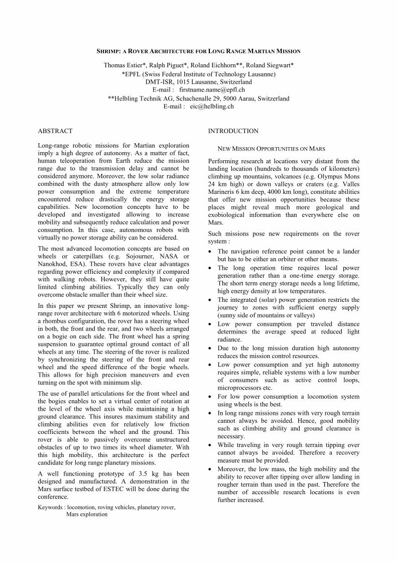
BOGIES
The bogies are the first key components of the rover.They provide the lateral stability during the motion evenon very rough terrain. To insure good adaptability of thebogie, it is necessary to set the pivot as low as possibleand in the same time to keep a maximum groundclearance. This problem is solved by using the parallelconfiguration showed on fig. 7 that bring the virtualcenter of rotation of the bogie at the height of the wheelaxis.
Fig 7: Explanation of the parallel bogie architecture
FRONT FORK
As shown on Fig. 6, a trajectory of the front wheel withan instantaneous center of rotation situated under thewheel axis is helpful to get on an obstacle. The secondgoal for the fork is to provide a maximum verticalamplitude for the wheel. To find the optimalconfiguration for the fork, we established the followingkinematic model (fig. 8) :
Fig 8: Parametric model of the fork
With the parametric equations of ξ, α et ψ as functionof the angle A,
φπα +−= AA2
)(
[ ][ ]
[ ][ ] �
�
�
�
��
�
�
⋅⋅⋅−+⋅⋅
−+⋅⋅⋅−++
��
�
�
��
�
�
⋅⋅⋅−+
⋅−=
)(cos22
)(cos2cos
)(cos2
)(coscos)(
22
2222
22
AcbcbdedAcbcba
AcbcbAbcaA
αα
ααψ
)()( AAA ψξ −=
we have all elements to establish the position of thepoint P as function of the angle A:
[ ][ ] ���
����
�
⋅+⋅⋅+⋅
=)(sin)sin()(cos)cos(
)(AhAcAhAc
APξξ
Finally, we chose the different parameters to get thetrajectory shown on fig. 9. The horizontal line is theheight of the wheel axis when the robot is on ahorizontal plane. Note that the characteristic of the
trajectory under this line is needed to insure a goodstability when the rover is on a convex ground.
Fig 9: Trajectories of the wheel axis of the front fork
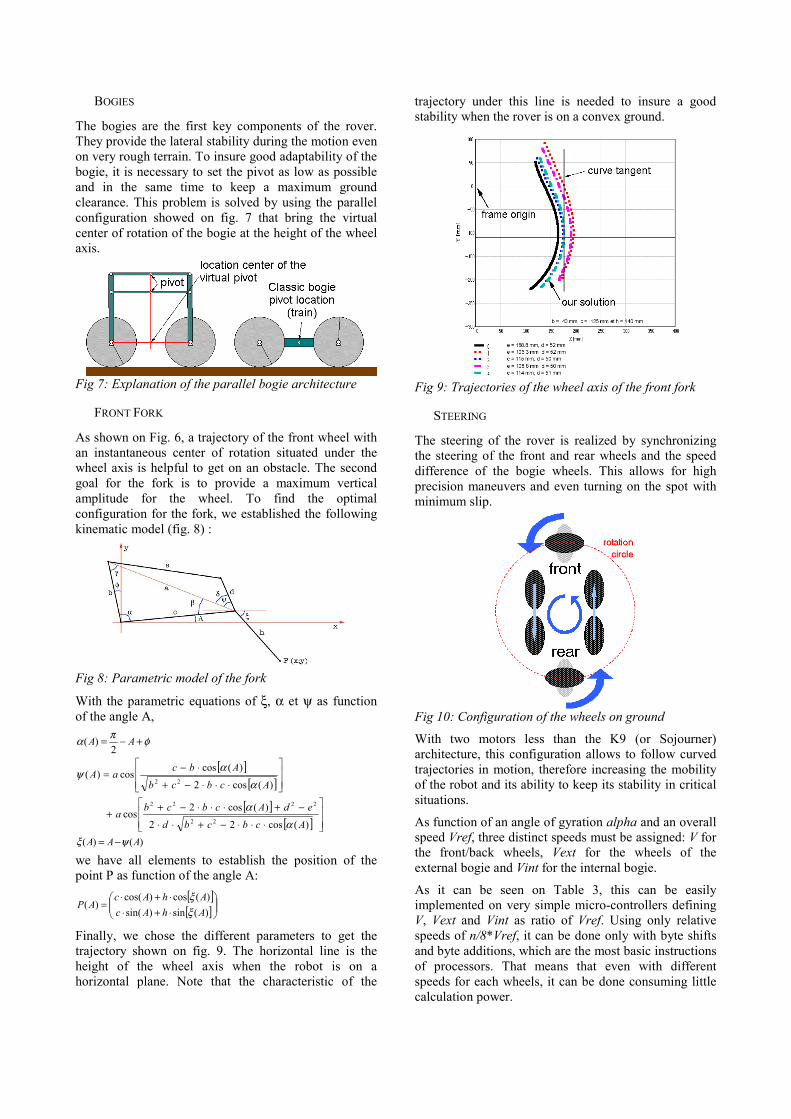
STEERING
The steering of the rover is realized by synchronizingthe steering of the front and rear wheels and the speeddifference of the bogie wheels. This allows for highprecision maneuvers and even turning on the spot withminimum slip.
Fig 10: Configuration of the wheels on ground
With two motors less than the K9 (or Sojourner)architecture, this configuration allows to follow curvedtrajectories in motion, therefore increasing the mobilityof the robot and its ability to keep its stability in criticalsituations.
As function of an angle of gyration alpha and an overallspeed Vref, three distinct speeds must be assigned: V forthe front/back wheels, Vext for the wheels of theexternal bogie and Vint for the internal bogie.
As it can be seen on Table 3, this can be easilyimplemented on very simple micro-controllers definingV, Vext and Vint as ratio of Vref. Using only relativespeeds of n/8*Vref, it can be done only with byte shiftsand byte additions, which are the most basic instructionsof processors. That means that even with differentspeeds for each wheels, it can be done consuming littlecalculation power.
alpha Vext V Vint0 1 1 1
10 1 7/8 6/820 1 7/8 5/830 1 7/8 4/840 1 7/8 2/850 1 7/8 1/860 1 1 -070 7/8 1 - 2/880 6/8 1 - 4/890 5/8 1 - 5/8
Table 3: Simple implementation of different wheelspeeds as function of the steering angle
RECOVERY STRATEGY FROM TIPPING OVER
Due to the extremely challenging terrain in which therobot will move about, the risk of falling and tippingover can’t be ignored and a recovery strategy has to beestablished.
An interesting solution lies in the use of the robotic armwhich has been designed especially for this robot withthe following guidelines:• Low position of the center of gravity and low inertia,
even in fully deployed configuration.• Ability to position tools (micro-camera, micro-
spectrometer, drill, etc.) around objects of interest atthe ground level.
• Ability to mechanically clean the whole surface ofthe solar panels.
• Ability to move a panoramic-camera in high positionfor reconnaissance purposes
• Possibility to recover the robot after a tipping over.
Fig 11: Various configuration of the robotic arm.
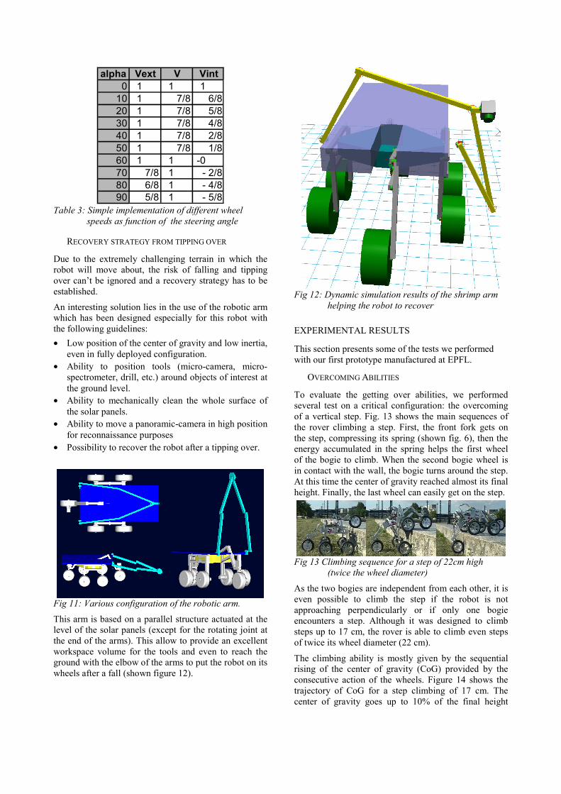
This arm is based on a parallel structure actuated at thelevel of the solar panels (except for the rotating joint atthe end of the arms). This allow to provide an excellentworkspace volume for the tools and even to reach theground with the elbow of the arms to put the robot on itswheels after a fall (shown figure 12).
Fig 12: Dynamic simulation results of the shrimp armhelping the robot to recover
EXPERIMENTAL RESULTS
This section presents some of the tests we performedwith our first prototype manufactured at EPFL.
OVERCOMING ABILITIES
To evaluate the getting over abilities, we performedseveral test on a critical configuration: the overcomingof a vertical step. Fig. 13 shows the main sequences ofthe rover climbing a step. First, the front fork gets onthe step, compressing its spring (shown fig. 6), then theenergy accumulated in the spring helps the first wheelof the bogie to climb. When the second bogie wheel isin contact with the wall, the bogie turns around the step.At this time the center of gravity reached almost its finalheight. Finally, the last wheel can easily get on the step.
Fig 13 Climbing sequence for a step of 22cm high(twice the wheel diameter)
As the two bogies are independent from each other, it iseven possible to climb the step if the robot is notapproaching perpendicularly or if only one bogieencounters a step. Although it was designed to climbsteps up to 17 cm, the rover is able to climb even stepsof twice its wheel diameter (22 cm).
The climbing ability is mostly given by the sequentialrising of the center of gravity (CoG) provided by theconsecutive action of the wheels. Figure 14 shows thetrajectory of CoG for a step climbing of 17 cm. Thecenter of gravity goes up to 10% of the final height

when the front wheel is on the top of the step (fig 12b).Then the first bogie wheel, helped by the action of thefront fork, brings the CoG to 50%. The second bogiewheel and the rear wheel contribute each forapproximately 25%. It can be seen that the mechanicalstructure allows a smooth movement of the CoG.
90%75%
50%
25%10%
Fig 14: Trajectory of the gravity center.
OFF-ROAD ABILITIES
The rover demonstrates excellent stability in bothsmooth and rough terrain. It still moves with a lateral orfrontal inclination of 40° (Fig 15, above) and is able toovercome obstacles like rocks even with a single bogie(fig.15, bellow). The rover was tested in various terrains(sandy and gravelly soil) and showed that itsarchitecture was well adapted for fields motion even indunes or in furrows.
Fig 15: Off-road stability test
Using the models described in [WIL97], we computedthe Mean Free Path (MFP) for the two Viking landingsites (VL1 and VL2). We set the height of passivelyclimbable obstacles to 17 cm instead of the true value oftwice its wheel diameter because there is at this time noheavy payload on the rover. For VL1, we obtained avalue of 35.7 (Sojourner: 9.6). For VL2, the MFP is 5.4(Sojourner: 2.4). This is a clue to say that this roverarchitecture is an excellent candidate for long rangemissions.
CONCLUSION
The presented concept demonstrator proves thefeasibility of the locomotion concept using wheels forlow power consumption and yet achieving remarkablerough terrain mobility. This is the basis for long rangemissions to remote research sites even in verychallenging environments with important slope andconsiderable number of obstacles. On Mars, it offersnew scientific opportunities to reach places which arerich in geological and exobiological information.
The most crucial subsystems for this long range roverare the power train including the energy storage, thethermal subsystem, the autonomous navigation system,the recovery from tipping over, the communicationsystem and the miniaturized payload.In order to integrate all these subsystems successfullyinto a whole rover:• a mission must be chosen,• budgets and requirements defined and• solution concepts for all subsystems developed.The work for the most challenging subsystems like thethermal subsystem and the autonomous navigationsystem should be attacked first as they contain the mostdevelopment risk. Specially for the autonomousnavigation subsystem another concept demonstrator isneeded for testing over long distances in rough terrain.
For autonomous systems reliability and thereforesimplicity must be the most important design guideline.
Although a further development of the concept to aspace proof level still requires substantial efforts, thenew order of possibilities should justify it.
REFERENCES
[EST00] T. Estier, Y. Crausaz, B. Merminod, M. Lauria,R.Piguet, R. Siegwart, “An innovative SpaceRover with Extended Climbing Alilities”,Proceedings of Space and Robotics 2000,Albuquerque, USA, February 27-March 2, 2000.
[LAN91] G. A. Landis, J. Appelbaum, NASA LewisResearch Center,” Photovoltaic Power Options forMars”, Space Power, Volume 10 Number 2, pp225-237 (1991)
[LAN97] G. A. Landis, P. P. Jenkins, NASA LewisResearch Center, “Dust on Mars”, Proceedings ofthe 26th IEEE Photovoltaic SpecialistsConference, pp. 865-869, 1997
[STO96] H. W. Stone, “Mars Pathfinder Microrover: ALow-Cost, Low-Power Spacecraft”, Proceedingsof the 1996 AIAA Forum on AdvancedDevelopments in Space Robotics, Madison WI,1996.
[WIL97] B. Wilcox, A. Nasif, R. Welch, “Implications ofMartian Rock Distributions on Rover Scaling”,Planetary Society International Conference onMobile Robots and Rover Roundup, SantaMonica, 1997.