
SHOWER PUMP Installation & User Guide - QS Supplies€¦ · 1 THESE INSTRUCTIONS ARE TO BE LEFT...
24
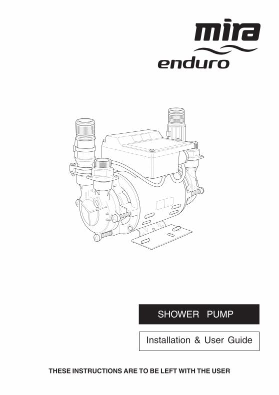
THESE INSTRUCTIONS ARE TO BE LEFT WITH THE USER Installation & User Guide SHOWER PUMP
-
Upload
truongnhan -
Category
Documents
-
view
217 -
download
1
Transcript of SHOWER PUMP Installation & User Guide - QS Supplies€¦ · 1 THESE INSTRUCTIONS ARE TO BE LEFT...
1
THESE INSTRUCTIONS ARE TO BE LEFT WITH THE USER
Installation & User Guide
SHOWER PUMP
2
INDEXIMPORTANT SAFETY INFORMATION 3
INTRODUCTION 5
DESCRIPTION 5
OPERATION 6
PACK CONTENTS 6
DIMENSIONS 7
SPECIFICATIONSWeight 8Ambient Temperature 8Electrical 8Water 8Standards and Approvals 8Plumbing Connections 9
INSTALLATION
General 10Procedure 11
COMMISSIONING 16
FAULT DIAGNOSIS 17
MAINTENANCEGeneral 20Storage 20
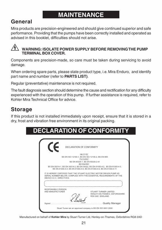
DECLARATION OF CONFORMITY 21
SPARE PARTSSpare Parts List 22Spare Parts Diagram 23
CUSTOMER CARE Back Cover
3
1. Warning!1.1. Products manufactured by us are safe and without risk provided they are installed,
used and maintained in good working order in accordance with our instructions andrecommendations.
1.2. THIS APPLIANCE MUST BE EARTHED. ENSURE SUPPLEMENTARYBONDING COMPLIES WITH THE "REQUIREMENTS FOR ELECTRICALINSTALLATIONS".
In accordance with the current edition of ‘The Plugs and Sockets (Safety)Regulations' in force at the time of installation, this Mira Enduro is intended to bepermanently connected to the fixed electrical wiring of the mains system.
1.3. The Mira Enduro must not be fitted where it may be exposed to freezingconditions. Make sure that any pipework that could become frozen is properlyinsulated.
1.4. DO NOT operate the Mira Enduro if it is frozen. Allow the Mira Enduro to thawbefore using again.
1.5. DO NOT operate the Mira Enduro if water leaks from the unit, maintenance willbe required before the Mira Enduro can be safely used.
1.6. DO NOT allow the Mira Enduro to be run dry.
1.7. DO NOT run the pump without the guards and covers correctly fitted.
1.8. The flow of air around the motor must be dust free and unimpeded as the pumpmotor is air cooled.
1.9. The inclusion of a Residual Current Device (RCD) (Earth trip) with a trip currentof 30mA is recommended. This may already be part of the consumer unit.
1.10.There are no user serviceable components beneath the cover of the Mira Enduro.Only a competent tradesperson should remove the cover.
1.11. If any of the following conditions occur, isolate the electricity and water suppliesand refer to “Consumer Care”, on the back page of this guide.
1.11.1. If the guards and covers are not correctly fitted and water has entered.1.11.2. If the guards or covers are damaged.1.11.3. If the Mira Enduro begins to make an odd noise, smell or smoke.1.11.4. If the Mira Enduro shows signs of a distinct change in performance,
indicating a need for maintenance.1.11.5. If the Mira Enduro is frozen.
1.12.Turn off the electrical and water supplies before removing guards or covers. Theelectricity must be turned off at the mains and the appropriate circuit fuseremoved, if applicable.
IMPORTANT SAFETY INFORMATION
4
1.13.Mains connections are exposed when the guards and covers are removed.
1.14.Moving parts are exposed when the guards and covers are removed.
1.15.Refer to the wiring diagram before making any electrical connections.
1.16.Ensure all electrical connections are tight, to prevent overheating.
2. Caution!2.1. Read all of these instructions and retain this guide for later use.
2.2. Pass on this guide in the event of change of ownership of the installation site.
2.3. Follow all warnings, cautions and instructions contained in this guide.
2.4. Follow all warnings, cautions and instructions contained on or inside the MiraEnduro.
2.5. The electrical installation must comply with the “Requirements for ElectricalInstallations” commonly referred to as the IEE Wiring Regulations, or anyparticular regulations and practices specified by the local electricity supplycompany, in force at the time of installation. The installation should be carried outby an electrician or contractor who is registered or is a member of an associationsuch as:
2.5.1. National Inspection Council for Electrical Installation and Contracting(NICEIC), throughout the UK.
2.5.2. The Electrical Contractors Association (ECA), England and Wales.2.5.3. The Electrical Contractors Association of Scotland (ECAS).
2.6. The plumbing installation must comply with Water Supply Regulations/Bye-laws(Scotland), Building Regulations or any particular regulations and practices,specified by the local water company or water undertakers. The installation shouldbe carried out by a plumber or contractor who is registered, or is a member of, anassociation such as:
2.6.1. Institute of Plumbing (IPHE), throughout the UK.2.6.2. National Association of Plumbing, Heating and Mechanical Services
Contractors (NAPH & MSC), England and Wales.2.6.3. Scottish and Northern Ireland Plumbing Employers’ Federation (SNIPEF),
Scotland and Northern Ireland.
2.7 System configurations or pump applications other than those shown (seeFigure 3) may cause inefficient or impaired operation of the system, which maydamage the pump unit. If the system configurations shown are not possible,consult Kohler Mira for advice before commencing installation.
2.8. Anyone who may have difficulty understanding or operating the controls of anyshower should be attended whilst showering. Particular consideration should begiven to the young, the elderly, the infirm, or anyone inexperienced in the correctoperation of the controls.
2.9. When the Mira Enduro has reached the end of its serviceable life, it should bedisposed of in a safe manner, in accordance with current local authority recycling,or waste disposal policy.
5
INTRODUCTIONThank you for purchasing a quality Mira product. To enjoy the full potential of your newproduct, please take time to read this guide thoroughly, having done so, keep it safefor future reference.
DESCRIPTIONThe Mira Enduro twin impeller regenerative pump is designed to receive a hot andcold gravity supply and provide a pressurised hot and cold supply to a mixing valve,refer to Figure 2.
Pump LocationThe pump is more effective when pushing water along a pipe rather than pulling. Thusthe pump is best positioned as close to the hot water or blend water source as possibleto reduce cavitation (air bubbles) in the pipes. The greater the static (inlet) waterpressure on the pump the better it will operate (see Fig. 2). Thus positioning a pump athigh level is not advantageous, and may result in inferior performance.
If it is not possible to locate the pump in the preferred area due to site limitations andit is necessary to position the pump at high level, or in a position above the secondarytapping that feeds the pump, then there is an increased risk of air locks. This riskmust be eliminated.
Due consideration should be given to the pump position as any noise generated maybe amplified by installation conditions such as reverberant panels, bare floorboards,etc.
Make sure adequate free ventilation is provided (minimum clearance of 80 mm aroundall sides of pump).
The hot water storage temperature should not exceed 60oC. Operation at thistemperature will also reduce the rate of formation of limescale in the system.
The stored hot and cold water volumes should be sufficient for the required duty,typical flow rates for a shower outlet are 10 l/min. Instantaneous or combination heatersare not suitable. It is not recommended that other services use the same feed pipeworkas the mixer valve or pump unit as operation problems may occur.
6
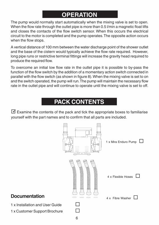
PACK CONTENTS
Examine the contents of the pack and tick the appropriate boxes to familiariseyourself with the part names and to confirm that all parts are included.
The pump would normally start automatically when the mixing valve is set to open.When the flow rate through the outlet pipe is more than 0.5 l/min a magnetic float liftsand closes the contacts of the flow switch sensor. When this occurs the electricalcircuit to the motor is completed and the pump operates. The opposite action occurswhen the flow stops.
A vertical distance of 100 mm between the water discharge point of the shower outletand the base of the cistern would typically achieve the flow rate required. However,long pipe runs or restrictive terminal fittings will increase the gravity head required toproduce the required flow.
To overcome an initial low flow rate in the outlet pipe it is possible to by-pass thefunction of the flow switch by the addition of a momentary action switch connected inparallel with the flow switch (as shown in figure 8). When the mixing valve is set to onand the switch operated, the pump will run. The pump will maintain the necessary flowrate in the outlet pipe and will continue to operate until the mixing valve is set to off.
OPERATION
1 x Mira Enduro Pump
4 x Flexible Hoses
4 x Fibre Washer Documentation
1 x Installation and User Guide
1 x Customer Support Brochure
7
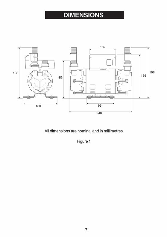
All dimensions are nominal and in millimetres
DIMENSIONS
Figure 1
102
166198198
130
248
96
153
8
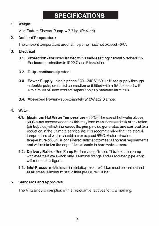
SPECIFICATIONS1. Weight
Mira Enduro Shower Pump = 7.7 kg (Packed)
2. Ambient Temperature
The ambient temperature around the pump must not exceed 40oC.
3. Electrical
3.1. Protection - the motor is fitted with a self-resetting thermal overload trip.Enclosure protection to IP22 Class F insulation.
3.2. Duty - continuously rated.
3.3. Power Supply - single phase 230 - 240 V, 50 Hz fused supply througha double pole, switched connection unit fitted with a 5A fuse and witha minimum of 3mm contact seperation gap between terminals.
3.4. Absorbed Power - approximately 518W at 2.3 amps.
4. Water
4.1. Maximum Hot Water Temperature - 65oC. The use of hot water above60oC is not recommended as this may lead to an increased risk of cavitation,(air bubbles) which increases the pump noise generated and can lead to areduction in the ultimate service life. It is recommended that the storedtemperature of water should never exceed 65oC. A stored watertemperature of 60oC is considered sufficient to meet all normal requirementsand will minimize the deposition of scale in hard water areas.
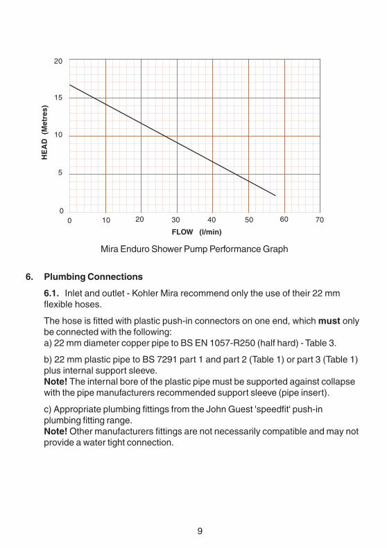
4.2. Delivery Rates - See Pump Performance Graph. This is for the pumpwith external flow switch only. Terminal fittings and associated pipe workwill reduce this figure.
4.3. Inlet Pressure - Minimum inlet static pressure 0.1 bar must be maintainedat all times. Maximum static inlet pressure 1.4 bar
5. Standards and Approvals
The Mira Enduro complies with all relevant directives for CE marking.
9
6. Plumbing Connections
6.1. Inlet and outlet - Kohler Mira recommend only the use of their 22 mmflexible hoses.
The hose is fitted with plastic push-in connectors on one end, which must onlybe connected with the following:a) 22 mm diameter copper pipe to BS EN 1057-R250 (half hard) - Table 3.
b) 22 mm plastic pipe to BS 7291 part 1 and part 2 (Table 1) or part 3 (Table 1)plus internal support sleeve.Note! The internal bore of the plastic pipe must be supported against collapsewith the pipe manufacturers recommended support sleeve (pipe insert).
c) Appropriate plumbing fittings from the John Guest 'speedfit' push-inplumbing fitting range.Note! Other manufacturers fittings are not necessarily compatible and may notprovide a water tight connection.
Mira Enduro Shower Pump Performance Graph
20
15
10
5
0
HE
AD
(M
etre
s)
0 10 20 30 40 50 60 70
FLOW (l/min)
10
INSTALLATION
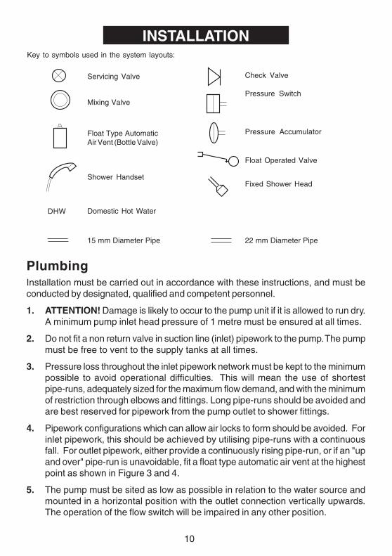
PlumbingInstallation must be carried out in accordance with these instructions, and must beconducted by designated, qualified and competent personnel.
1. ATTENTION! Damage is likely to occur to the pump unit if it is allowed to run dry.A minimum pump inlet head pressure of 1 metre must be ensured at all times.
2. Do not fit a non return valve in suction line (inlet) pipework to the pump. The pumpmust be free to vent to the supply tanks at all times.
3. Pressure loss throughout the inlet pipework network must be kept to the minimumpossible to avoid operational difficulties. This will mean the use of shortestpipe-runs, adequately sized for the maximum flow demand, and with the minimumof restriction through elbows and fittings. Long pipe-runs should be avoided andare best reserved for pipework from the pump outlet to shower fittings.
4. Pipework configurations which can allow air locks to form should be avoided. Forinlet pipework, this should be achieved by utilising pipe-runs with a continuousfall. For outlet pipework, either provide a continuously rising pipe-run, or if an "upand over" pipe-run is unavoidable, fit a float type automatic air vent at the highestpoint as shown in Figure 3 and 4.
5. The pump must be sited as low as possible in relation to the water source andmounted in a horizontal position with the outlet connection vertically upwards.The operation of the flow switch will be impaired in any other position.
15 mm Diameter Pipe 22 mm Diameter Pipe
Float Type AutomaticAir Vent (Bottle Valve)
Domestic Hot Water
Shower Handset
Mixing Valve
Servicing Valve
Pressure Accumulator
Pressure Switch
Fixed Shower Head
Check Valve
Float Operated Valve
DHW
Key to symbols used in the system layouts:
11
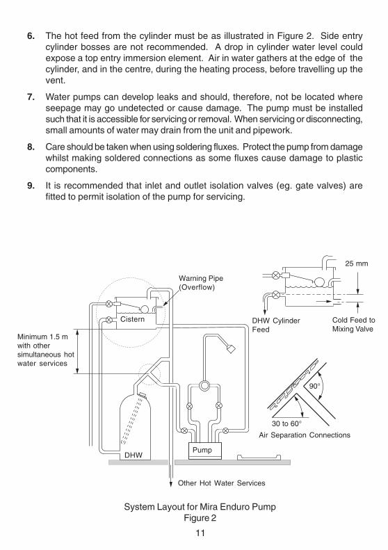
6. The hot feed from the cylinder must be as illustrated in Figure 2. Side entrycylinder bosses are not recommended. A drop in cylinder water level couldexpose a top entry immersion element. Air in water gathers at the edge of thecylinder, and in the centre, during the heating process, before travelling up thevent.
7. Water pumps can develop leaks and should, therefore, not be located whereseepage may go undetected or cause damage. The pump must be installedsuch that it is accessible for servicing or removal. When servicing or disconnecting,small amounts of water may drain from the unit and pipework.
8. Care should be taken when using soldering fluxes. Protect the pump from damagewhilst making soldered connections as some fluxes cause damage to plasticcomponents.
9. It is recommended that inlet and outlet isolation valves (eg. gate valves) arefitted to permit isolation of the pump for servicing.
System Layout for Mira Enduro PumpFigure 2
Minimum 1.5 mwith othersimultaneous hotwater services
Cistern
Warning Pipe(Overflow)
Other Hot Water Services
DHWPump
30 to 60°
Air Separation Connections
DHW CylinderFeed
25 mm
Cold Feed toMixing Valve
90°
12
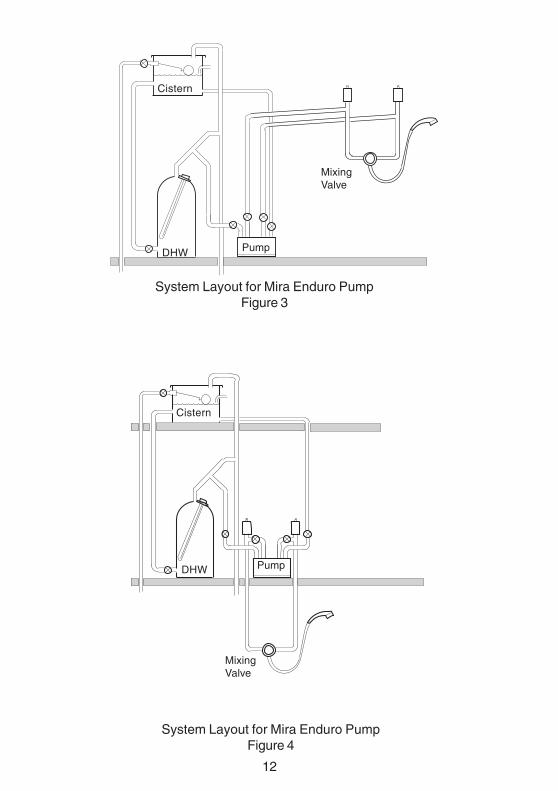
System Layout for Mira Enduro PumpFigure 3
Cistern
DHW Pump
MixingValve
System Layout for Mira Enduro PumpFigure 4
DHW Pump
MixingValve
Cistern
13
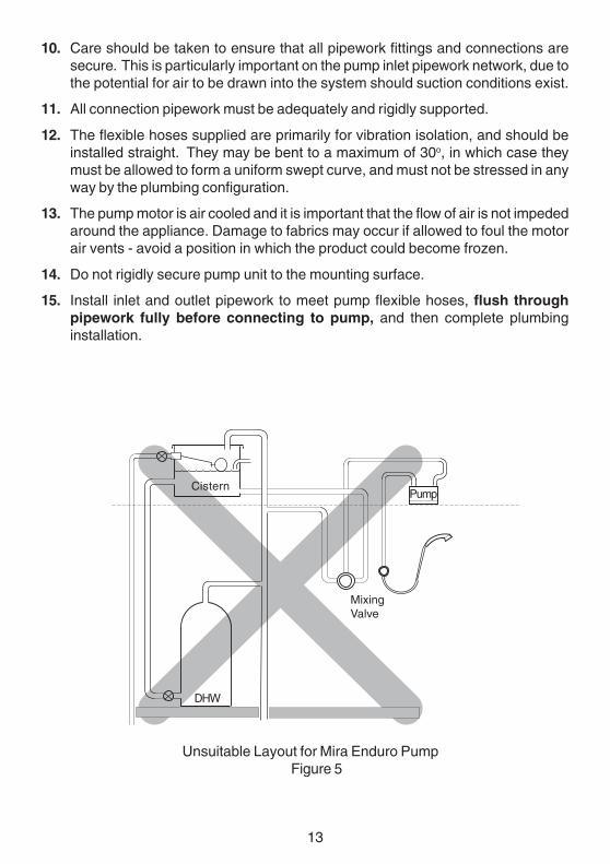
10. Care should be taken to ensure that all pipework fittings and connections aresecure. This is particularly important on the pump inlet pipework network, due tothe potential for air to be drawn into the system should suction conditions exist.
11. All connection pipework must be adequately and rigidly supported.
12. The flexible hoses supplied are primarily for vibration isolation, and should beinstalled straight. They may be bent to a maximum of 30o, in which case theymust be allowed to form a uniform swept curve, and must not be stressed in anyway by the plumbing configuration.
13. The pump motor is air cooled and it is important that the flow of air is not impededaround the appliance. Damage to fabrics may occur if allowed to foul the motorair vents - avoid a position in which the product could become frozen.
14. Do not rigidly secure pump unit to the mounting surface.
15. Install inlet and outlet pipework to meet pump flexible hoses, flush throughpipework fully before connecting to pump, and then complete plumbinginstallation.
DHW
Pump
Unsuitable Layout for Mira Enduro PumpFigure 5
Cistern
MixingValve
14
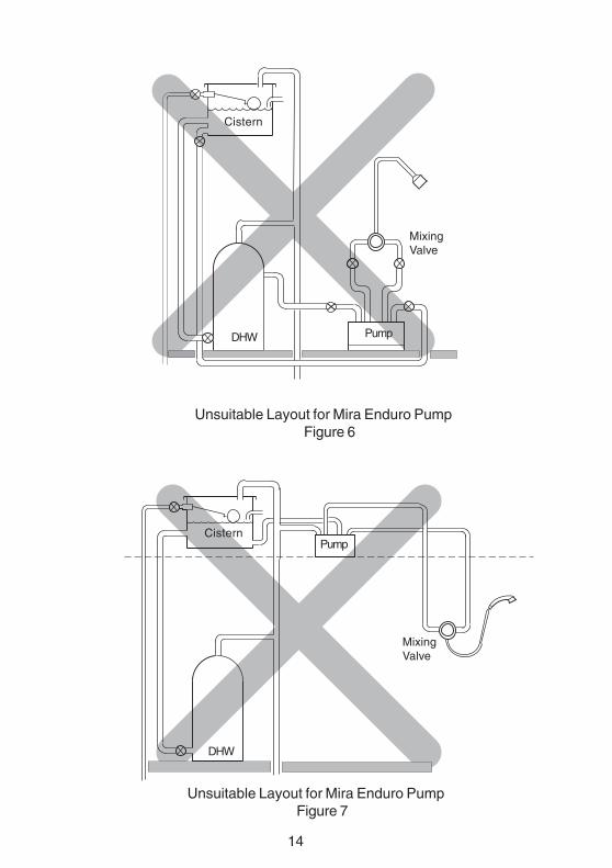
Cistern
Unsuitable Layout for Mira Enduro PumpFigure 6
Unsuitable Layout for Mira Enduro PumpFigure 7
CisternPump
DHW
DHW Pump
MixingValve
MixingValve
15
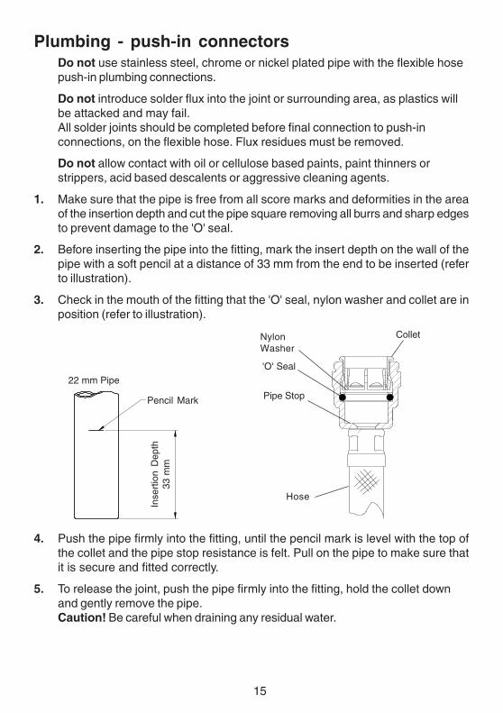
Plumbing - push-in connectorsDo not use stainless steel, chrome or nickel plated pipe with the flexible hosepush-in plumbing connections.
Do not introduce solder flux into the joint or surrounding area, as plastics willbe attacked and may fail.All solder joints should be completed before final connection to push-inconnections, on the flexible hose. Flux residues must be removed.
Do not allow contact with oil or cellulose based paints, paint thinners orstrippers, acid based descalents or aggressive cleaning agents.
1. Make sure that the pipe is free from all score marks and deformities in the areaof the insertion depth and cut the pipe square removing all burrs and sharp edgesto prevent damage to the 'O' seal.
2. Before inserting the pipe into the fitting, mark the insert depth on the wall of thepipe with a soft pencil at a distance of 33 mm from the end to be inserted (referto illustration).
3. Check in the mouth of the fitting that the 'O' seal, nylon washer and collet are inposition (refer to illustration).
Pencil Mark
22 mm Pipe
Inse
rtio
n D
epth
33 m
m
4. Push the pipe firmly into the fitting, until the pencil mark is level with the top ofthe collet and the pipe stop resistance is felt. Pull on the pipe to make sure thatit is secure and fitted correctly.
5. To release the joint, push the pipe firmly into the fitting, hold the collet downand gently remove the pipe.Caution! Be careful when draining any residual water.
NylonWasher
Pipe Stop
'O' Seal
Collet
Hose
16
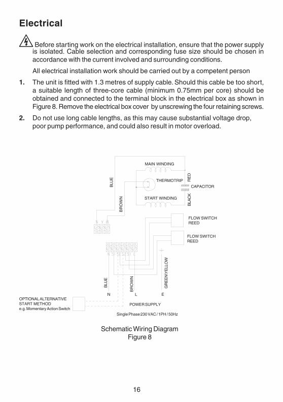
Electrical
Before starting work on the electrical installation, ensure that the power supplyis isolated. Cable selection and corresponding fuse size should be chosen inaccordance with the current involved and surrounding conditions.
All electrical installation work should be carried out by a competent person
1. The unit is fitted with 1.3 metres of supply cable. Should this cable be too short,a suitable length of three-core cable (minimum 0.75mm per core) should beobtained and connected to the terminal block in the electrical box as shown inFigure 8. Remove the electrical box cover by unscrewing the four retaining screws.
2. Do not use long cable lengths, as this may cause substantial voltage drop,poor pump performance, and could also result in motor overload.
POWER SUPPLY
Single Phase 230 VAC / 1PH / 50Hz
Schematic Wiring DiagramFigure 8
MAIN WINDING
BLU
E
BLA
CK
BR
OW
N
BLU
E
BR
OW
N
RE
D
FLOW SWITCHREED
FLOW SWITCHREED
CAPACITOR
THERMOTRIP
START WINDING
GR
EE
N\Y
ELL
OW
ELNOPTIONAL ALTERNATIVESTART METHODe.g. Momentary Action Switch
17
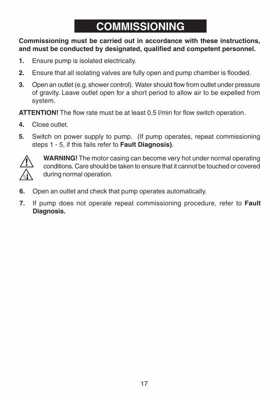
COMMISSIONINGCommissioning must be carried out in accordance with these instructions,and must be conducted by designated, qualified and competent personnel.
1. Ensure pump is isolated electrically.
2. Ensure that all isolating valves are fully open and pump chamber is flooded.
3. Open an outlet (e.g. shower control). Water should flow from outlet under pressureof gravity. Leave outlet open for a short period to allow air to be expelled fromsystem.
ATTENTION! The flow rate must be at least 0.5 l/min for flow switch operation.
4. Close outlet.
5. Switch on power supply to pump. (If pump operates, repeat commissioningsteps 1 - 5, if this fails refer to Fault Diagnosis).
WARNING! The motor casing can become very hot under normal operatingconditions. Care should be taken to ensure that it cannot be touched or coveredduring normal operation.
6. Open an outlet and check that pump operates automatically.
7. If pump does not operate repeat commissioning procedure, refer to FaultDiagnosis.
18
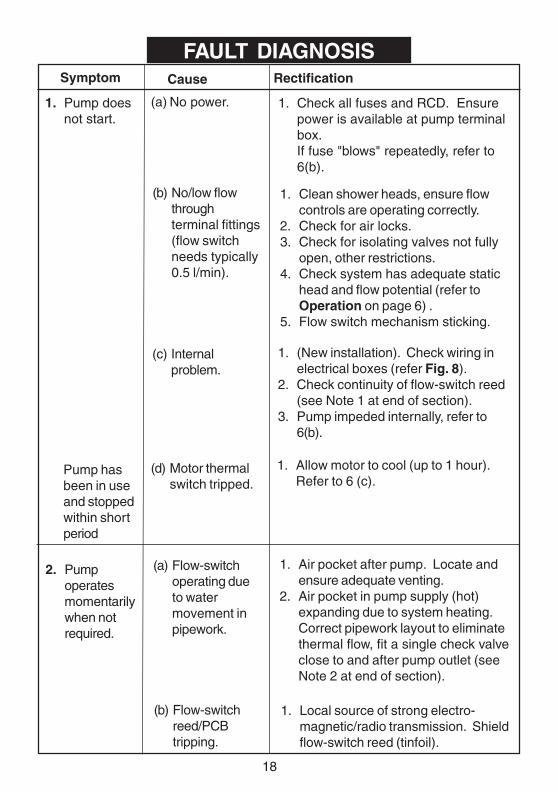
FAULT DIAGNOSISSymptom Rectification
(a) No power.1. Pump doesnot start.
Cause
1. Check all fuses and RCD. Ensurepower is available at pump terminalbox.If fuse "blows" repeatedly, refer to6(b).
(b) No/low flowthroughterminal fittings(flow switchneeds typically0.5 l/min).
1. Clean shower heads, ensure flowcontrols are operating correctly.
2. Check for air locks.3. Check for isolating valves not fully
open, other restrictions.4. Check system has adequate static
head and flow potential (refer toOperation on page 6) .
5. Flow switch mechanism sticking.
(d) Motor thermalswitch tripped.
1. Allow motor to cool (up to 1 hour).Refer to 6 (c).
1. (New installation). Check wiring inelectrical boxes (refer Fig. 8).
2. Check continuity of flow-switch reed(see Note 1 at end of section).
3. Pump impeded internally, refer to6(b).
2. Pumpoperatesmomentarilywhen notrequired.
(a) Flow-switchoperating dueto watermovement inpipework.
1. Air pocket after pump. Locate andensure adequate venting.
2. Air pocket in pump supply (hot)expanding due to system heating.Correct pipework layout to eliminatethermal flow, fit a single check valveclose to and after pump outlet (seeNote 2 at end of section).
(b) Flow-switchreed/PCBtripping.
1. Local source of strong electro-magnetic/radio transmission. Shieldflow-switch reed (tinfoil).
(c) Internalproblem.
Pump hasbeen in useand stoppedwithin shortperiod
19
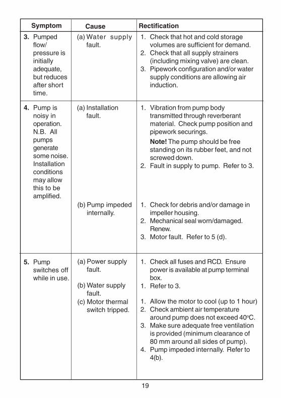
Symptom Rectification
(a) Water supplyfault.
3. Pumpedflow/pressure isinitiallyadequate,but reducesafter shorttime.
Cause
1. Check that hot and cold storagevolumes are sufficient for demand.
2. Check that all supply strainers(including mixing valve) are clean.
3. Pipework configuration and/or watersupply conditions are allowing airinduction.
(a) Installationfault.
1. Vibration from pump bodytransmitted through reverberantmaterial. Check pump position andpipework securings.
Note! The pump should be freestanding on its rubber feet, and notscrewed down.
2. Fault in supply to pump. Refer to 3.
(b) Pump impededinternally.
1. Check for debris and/or damage inimpeller housing.
2. Mechanical seal worn/damaged.Renew.
3. Motor fault. Refer to 5 (d).
4. Pump isnoisy inoperation.N.B. Allpumpsgeneratesome noise.Installationconditionsmay allowthis to beamplified.
(a) Power supplyfault.
1. Check all fuses and RCD. Ensurepower is available at pump terminalbox.
5. Pumpswitches offwhile in use.
1. Refer to 3.
1. Allow the motor to cool (up to 1 hour)2. Check ambient air temperature
around pump does not exceed 40oC.3. Make sure adequate free ventilation
is provided (minimum clearance of80 mm around all sides of pump).
4. Pump impeded internally. Refer to4(b).
(b) Water supplyfault.
(c) Motor thermalswitch tripped.
20
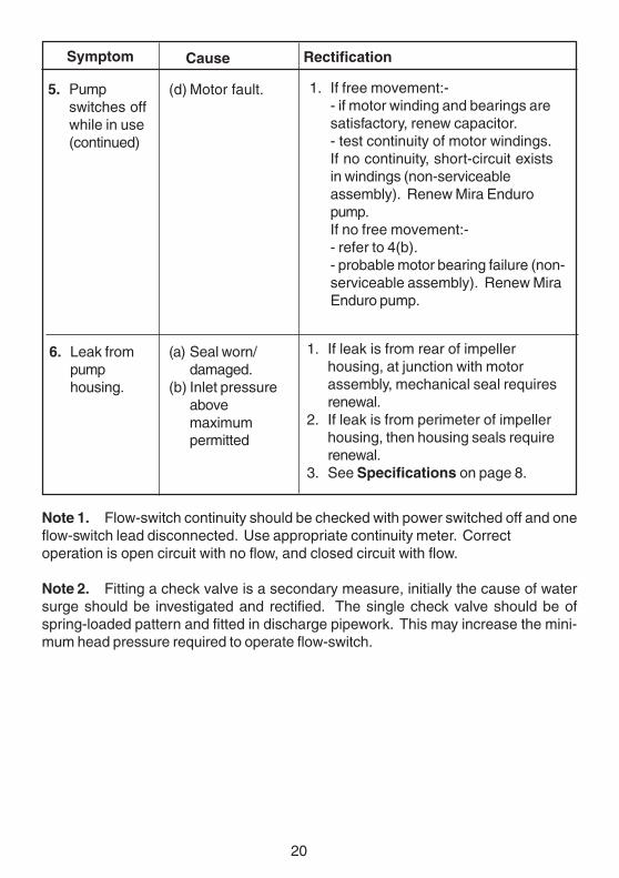
Note 1. Flow-switch continuity should be checked with power switched off and oneflow-switch lead disconnected. Use appropriate continuity meter. Correctoperation is open circuit with no flow, and closed circuit with flow.
Note 2. Fitting a check valve is a secondary measure, initially the cause of watersurge should be investigated and rectified. The single check valve should be ofspring-loaded pattern and fitted in discharge pipework. This may increase the mini-mum head pressure required to operate flow-switch.
Symptom RectificationCause
(a) Seal worn/damaged.
(b) Inlet pressureabovemaximumpermitted
1. If leak is from rear of impellerhousing, at junction with motorassembly, mechanical seal requiresrenewal.
2. If leak is from perimeter of impellerhousing, then housing seals requirerenewal.
3. See Specifications on page 8.
6. Leak frompumphousing.
5. Pumpswitches offwhile in use(continued)
(d) Motor fault. 1. If free movement:-- if motor winding and bearings aresatisfactory, renew capacitor.- test continuity of motor windings.If no continuity, short-circuit existsin windings (non-serviceableassembly). Renew Mira Enduropump.If no free movement:-- refer to 4(b).- probable motor bearing failure (non-serviceable assembly). Renew MiraEnduro pump.
21
MAINTENANCEGeneralMira products are precision-engineered and should give continued superior and safeperformance. Providing that the pumps have been correctly installed and operated asadvised in this booklet, difficulties should not arise.
WARNING: ISOLATE POWER SUPPLY BEFORE REMOVING THE PUMPTERMINAL BOX COVER.
Components are precision-made, so care must be taken during servicing to avoiddamage.
When ordering spare parts, please state product type, i.e. Mira Enduro, and identifypart name and number (refer to PARTS LIST).
Regular (preventative) maintenance is not required.
The fault diagnosis section should determine the cause and rectification for any difficultyexperienced with the operation of this pump. If further assistance is required, refer toKohler Mira Technical Office for advice.
StorageIf this product is not installed immediately upon receipt, ensure that it is stored in adry, frost and vibration free environment in its original packing.
Manufactured on behalf of Kohler Mira by Stuart Turner Ltd, Henley-on-Thames, Oxfordshire RG9 2AD
DECLARATION OF CONFORMITY
22
SPARE PARTS
Spare Parts List465.01 'O' Seal Pack - including Mechanical Seal (components identified 'A')
465.02 Flow Switch Module
465.03 Flow Switch Mechanism
465.04 Flexible Hose Assembly
465.05 Rubber Feet
465.06 Screw Pack (not illustrated)
465.07 PCB (not illustrated)
465.08 Impeller Assembly
465.09 Push Fit Pack (for flexible hose)
465.10 Capacitor (not illustrated)
465.11 Inlet Connector Housing
872.56 Cable Tie
23
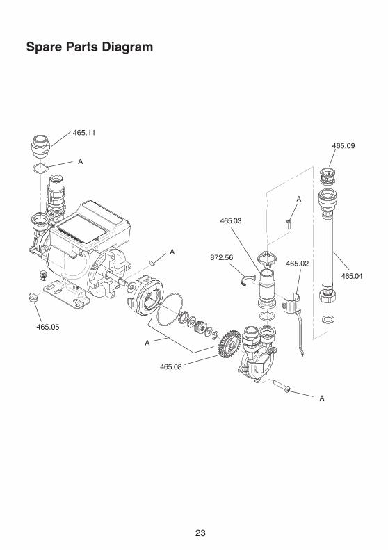
Spare Parts Diagram
465.02
465.03
465.04
465.05
465.08
465.11
872.56
465.09
A
A
A
A
A
24P4524 © Kohler Mira Limited,February 2005
Mira ShowersKohler Mira LtdCromwell Road,Cheltenham GL52 5EP.
Mira is a registered trade mark ofKohler Mira Limited.The company reserves the right toalter product specifications withoutnotice.
Customer ServiceSpare PartsWe maintain an extensive stock of spares, and aim to have functionalparts available for ten years from the date of final manufacture of theproduct.
Spares can be purchased from approved stockists or merchants(locations on request) or direct from Customer Services.
Spares direct will normally be despatched within two working days.Payment can be made by Visa or Mastercard at the time of ordering.Should payment by cheque be preferred a pro-forma invoice will besent.
Note! In the interests of safety, spares requiring exposure to mainsvoltages can only be sent to competent persons.
ServiceOur Service Force is available to provide a quality service at areasonable cost. You will have the assurance of a Mira trainedengineer/agent, genuine Mira spares – and a 12 month guarantee onthe repair.
Payment should be made directly to the ServiceEngineer/Agent, using Visa, Mastercard or a chequesupported by a banker’s card.
To contact usEngland, Scotland & WalesMira Showers Customer ServicesTelephone:0870 241 08888:30 am to 5:00 pm Working days (4:30 pm Friday)8:30 am to 12.30 pm SaturdayE-mail: [email protected]: 01242 282595By Post: Cromwell Road
CheltenhamGloucester GL52 5EP
Northern IrelandWm H Leech & Son LtdTelephone:028 9044 9257 – Mon to Fri 9 am-5pmFax: 028 9044 9234 – 24 hoursPost: Maryland Industrial Estate
Ballygowan RoadMoneyreagh, Co DownBT23 6BL
Republic of IrelandModern Plant LtdTelephone:01 4591344 – Mon to Fri 9am to 5pmFax: Dublin 01 4592329 – 24 hoursPost: Otter House
Naas RoadClondalkinDublin 22
Guarantee of Quality
Mira Showers guarantee your product against any defect in materialsor workmanship for the period shown in the Guarantee RegistrationDocument included with your shower.
Alternatively, to confirm the applicable guarantee period pleasecontact Customer Services.
To validate the guarantee, please return your completed registrationcard.
Within the guarantee period we will resolve defects, free of charge, byrepairing or replacing parts or modules as we may choose.
To be free of charge, service work must only be undertaken by MiraShowers or our approved agents in Northern Ireland and Republic ofIreland.
Service under this guarantee does not affect the expiry date. Theguarantee on any exchanged parts or product ends when the normalproduct guarantee period expires.
Not covered by this guarantee:
Damage or defects arising from incorrect installation, improper use orlack of maintenance, including build-up of limescale.
Damage or defects if the product is taken apart, repaired or modifiedby any person not authorised by Mira Showers or our approvedagents.
This guarantee is in addition to your statutory and other legal rights.
Before using your showerPlease take the time to read and understand theoperating and safety instructions detailed in this manual.
What to do if something goes wrongIf when you first use your shower it doesn’t function correctly, firstcontact your installer to check that installation and commissioning aresatisfactory and in accordance with the instructions in this manual.We are on-hand to offer you or your installer any advice you mayneed.
Should this not resolve the difficulty, simply contact our CustomerServices who will give every assistance, and if necessary arrange forour service engineer to visit.
If later the performance of your shower declines, consult this manualto see whether simple home maintenance is required. Please call ourCustomer Services to talk the difficulty through, request service underguarantee if applicable, or take advantage of our comprehensive After-Sales service.
As part of our quality and training programme calls may be recordedor monitored.
Our Customer Services Team is comprehensively trained to provideevery assistance you may need: help and advice, spare parts or aservice visit.