
SHOWER PUMP Installation & User Guide - QS€¦ · 1 Installation & User Guide SHOWER PUMP THESE...
24
Installation & User Guide SHOWER PUMP THESE INSTRUCTIONS ARE TO BE LEFT WITH THE USER
Transcript of SHOWER PUMP Installation & User Guide - QS€¦ · 1 Installation & User Guide SHOWER PUMP THESE...
1
Installation & User Guide
SHOWER PUMP
THESE INSTRUCTIONS ARE TO BE LEFT WITH THE USER
2ii
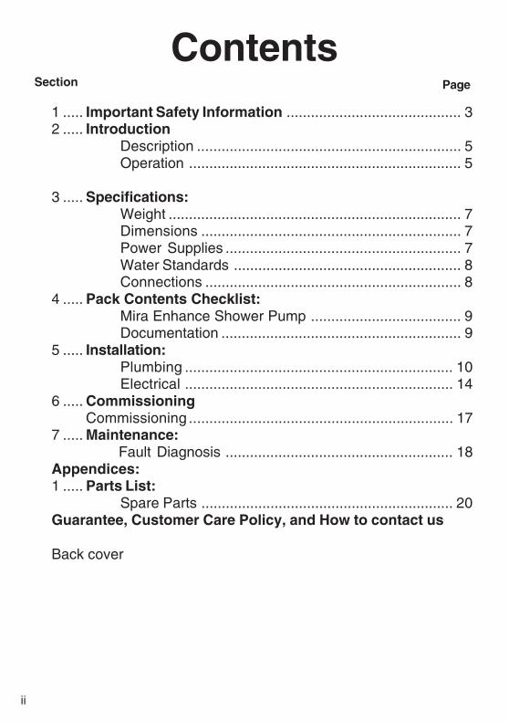
ContentsSection
1 ..... Important Safety Information ........................................... 32 ..... Introduction
Description ................................................................. 5Operation ................................................................... 5
3 ..... Specifications:Weight ........................................................................ 7Dimensions ................................................................ 7Power Supplies .......................................................... 7Water Standards ........................................................ 8Connections ............................................................... 8
4 ..... Pack Contents Checklist:Mira Enhance Shower Pump ..................................... 9Documentation ........................................................... 9
5 ..... Installation:Plumbing .................................................................. 10Electrical .................................................................. 14
6 ..... CommissioningCommissioning ................................................................. 17
7 ..... Maintenance:Fault Diagnosis ........................................................ 18
Appendices:1 ..... Parts List:
Spare Parts .............................................................. 20Guarantee, Customer Care Policy, and How to contact us
Back cover
Page
3
Section
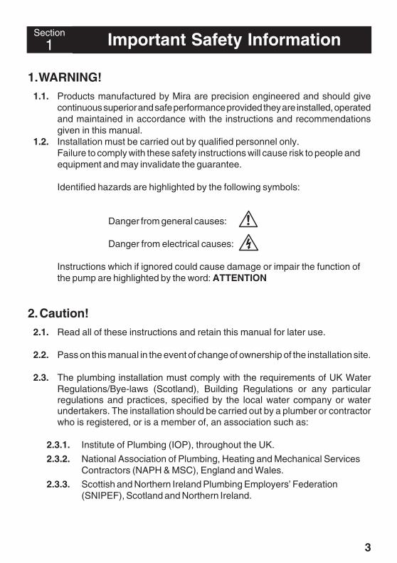
1 Important Safety Information
1. WARNING!1.1. Products manufactured by Mira are precision engineered and should give
continuous superior and safe performance provided they are installed, operatedand maintained in accordance with the instructions and recommendationsgiven in this manual.
1.2. Installation must be carried out by qualified personnel only.Failure to comply with these safety instructions will cause risk to people andequipment and may invalidate the guarantee.
Identified hazards are highlighted by the following symbols:
Danger from general causes:
Danger from electrical causes:
Instructions which if ignored could cause damage or impair the function ofthe pump are highlighted by the word: ATTENTION
2. Caution!2.1. Read all of these instructions and retain this manual for later use.
2.2. Pass on this manual in the event of change of ownership of the installation site.
2.3. The plumbing installation must comply with the requirements of UK WaterRegulations/Bye-laws (Scotland), Building Regulations or any particularregulations and practices, specified by the local water company or waterundertakers. The installation should be carried out by a plumber or contractorwho is registered, or is a member of, an association such as:
2.3.1. Institute of Plumbing (IOP), throughout the UK.
2.3.2. National Association of Plumbing, Heating and Mechanical ServicesContractors (NAPH & MSC), England and Wales.
2.3.3. Scottish and Northern Ireland Plumbing Employers’ Federation(SNIPEF), Scotland and Northern Ireland.
4
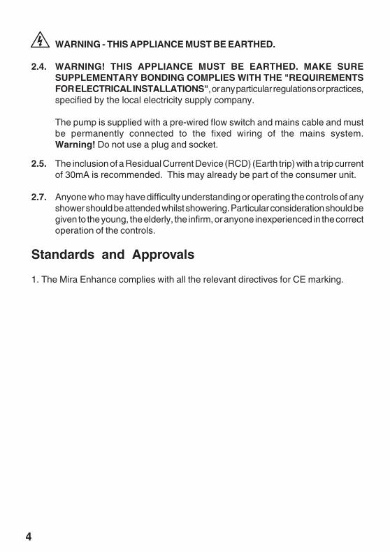
WARNING - THIS APPLIANCE MUST BE EARTHED.
2.4. WARNING! THIS APPLIANCE MUST BE EARTHED. MAKE SURESUPPLEMENTARY BONDING COMPLIES WITH THE "REQUIREMENTSFOR ELECTRICAL INSTALLATIONS", or any particular regulations or practices,specified by the local electricity supply company.
The pump is supplied with a pre-wired flow switch and mains cable and mustbe permanently connected to the fixed wiring of the mains system.Warning! Do not use a plug and socket.
2.5. The inclusion of a Residual Current Device (RCD) (Earth trip) with a trip currentof 30mA is recommended. This may already be part of the consumer unit.
2.7. Anyone who may have difficulty understanding or operating the controls of anyshower should be attended whilst showering. Particular consideration should begiven to the young, the elderly, the infirm, or anyone inexperienced in the correctoperation of the controls.
Standards and Approvals
1. The Mira Enhance complies with all the relevant directives for CE marking.
5
2Section Introduction
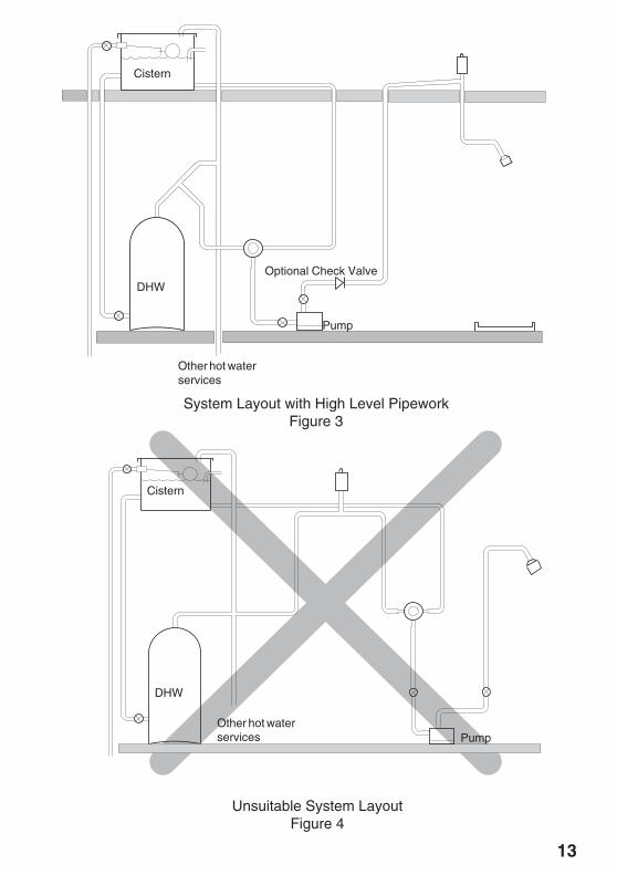
1. DescriptionThe Mira Enhance single impeller centrifugal pump is designed to receive a singlegravity feed from a mixing valve and provide a pressurized supply to a fixed showerhead or shower handset. (Refer to Figures 2 and 3). The pump is not suitable for aninstallation in the system layouts shown in Figures 4 and 5.
The pump is more effective when pushing water along a pipe rather than pulling. Thusthe pump is best positioned as close to the hot water or blend water source as possibleto reduce cavitation (air bubbles) in the pipes. The greater the static (inlet) waterpressure on the pump the better it will operate. Thus positioning a pump at high levelis not advantageous, and may result in inferior performance.
Due consideration should be made to the pump position as any noise generated maybe amplified by installation conditions such as reverberant panels etc. The pump motoris air cooled and it is important that the flow of air around the motor is not impeded. Thepump should be sited in a frost free area and inlet/outlet pipework layouts which cancreate significant airlocks are best avoided.
ATTENTION: Pipework on the outlet side of the pump that could be prone to airlockscan be fitted with a float-type automatic air vent (bottle vent) at the highest point asshown in Figure 3. This will ensure that air released in the hot water during the pumpingand heating process can be vented.
The stored hot and cold water volumes should be sufficient for the required duty.Typical minimum flow rates are 10 l/min for a pulsating handset or overhead shower.The manufacturer’s data for the outlet fittings should be consulted.
Thank you for purchasing a quality Mira product. To enjoy the full potential of your newproduct, please take time to read this guide thoroughly, having done so, keep it safefor future reference.
2. OperationThe pump would normally start automatically when the mixing valve is set to open. Thecontacts of the flow switch at the pump outlet close when the flow rate in the outlet pipeis more than 1.4 l/min. When this occurs the electrical circuit to the motor is completedand the pump operates. The opposite action occurs when the mixing valve is set toshut.
A vertical distance of 300 mm between the water discharge point through the showeroutlet and the base of the cistern would typically achieve the flow rate required.However, long pipe runs or restrictive terminal fittings will increase the gravity headrequired to produce the required flow.
6
To overcome an initial low flow rate in the outlet pipe it is possible to bypass the functionof the flow switch by the addition of a momentary action switch connected in parallelwith the flow switch (Refer to Figure 6). When the mixing valve is set to on and themomentary action switch operated, the pump will run. The pump will then maintain thenecessary flow rate in the outlet pipe and will continue to operate until the mixing valveis set to off.
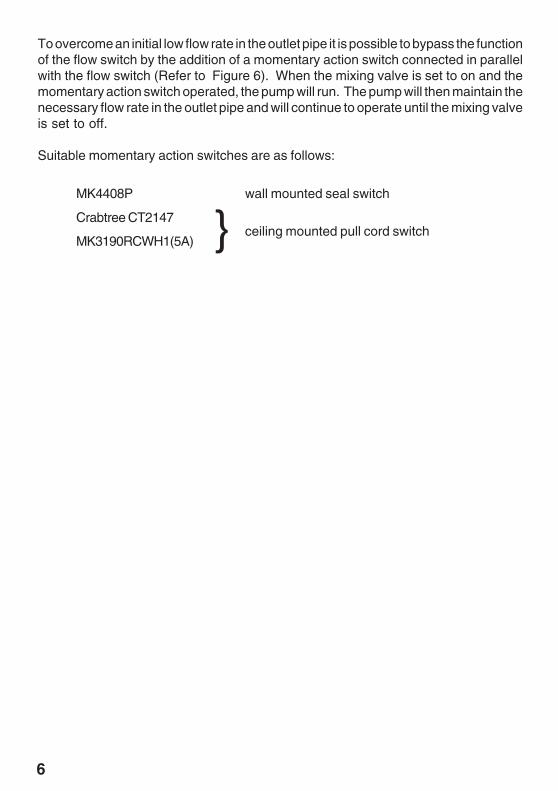
Suitable momentary action switches are as follows:
} ceiling mounted pull cord switch
MK4408P wall mounted seal switch
Crabtree CT2147
MK3190RCWH1(5A)
7
1. Weight
Mira Enhance Shower Pump = 2.7 kg (Pump only)
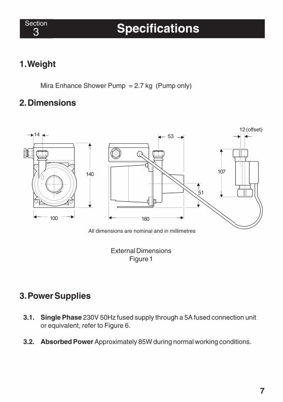
2. Dimensions
14
140
100
53
160
51
107
12 (offset)
All dimensions are nominal and in millimetres
External DimensionsFigure 1
3. Power Supplies
3.1. Single Phase 230V 50Hz fused supply through a 5A fused connection unitor equivalent, refer to Figure 6.
3.2. Absorbed Power Approximately 85W during normal working conditions.
3Section Specifications
8
4. Water Standards
4.1. This product complies with all relevant directives for CE marking.
4.2. Maximum Hot Water Temperature 80oC. It is recommended that storedwater temperatures should never exceed 65oC. The use of hot water above60oC may lead to cavitation (air bubbles) which will increase pump noise andreduce the service life of the product. A temperature of 60oC is consideredsufficient to meet all normal requirements and will minimize the depositionof scale in hard water areas.
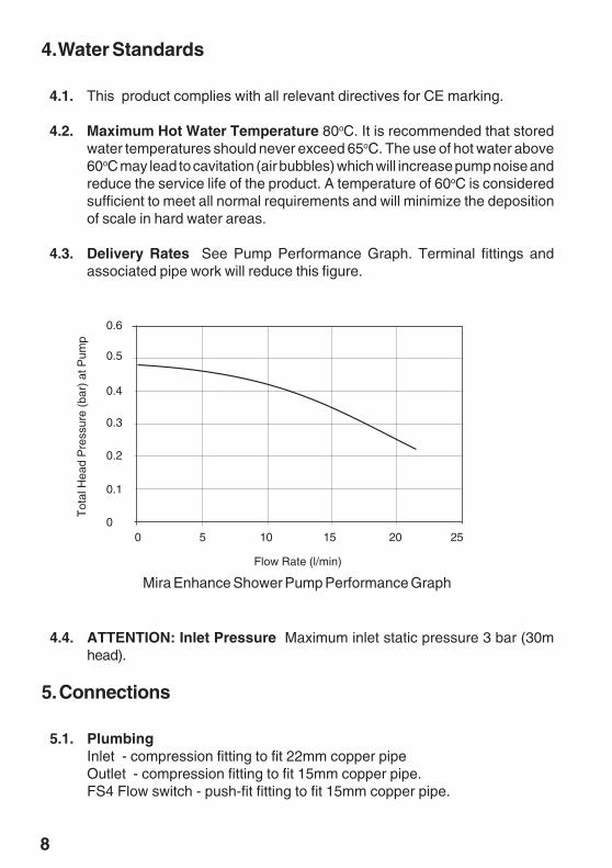
4.3. Delivery Rates See Pump Performance Graph. Terminal fittings andassociated pipe work will reduce this figure.
0.6
0.5
0.4
0.3
0.2
0.1
00 5 10 15 20 25
Mira Enhance Shower Pump Performance Graph
Flow Rate (l/min)
Tot
al H
ead
Pre
ssur
e (b
ar)
at P
ump
4.4. ATTENTION: Inlet Pressure Maximum inlet static pressure 3 bar (30mhead).
5. Connections
5.1. PlumbingInlet - compression fitting to fit 22mm copper pipeOutlet - compression fitting to fit 15mm copper pipe.FS4 Flow switch - push-fit fitting to fit 15mm copper pipe.
9
4Section Pack Contents Checklist
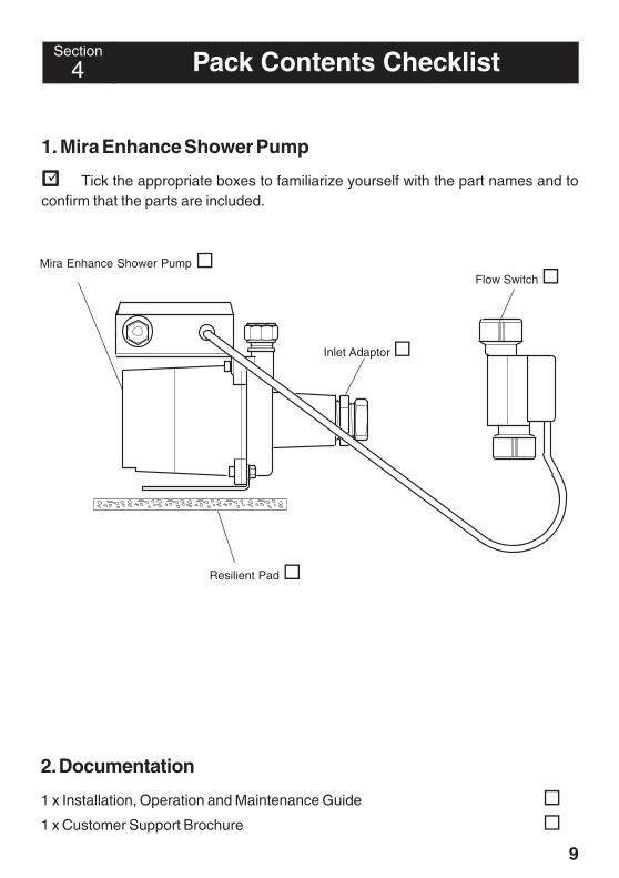
1. Mira Enhance Shower Pump
Tick the appropriate boxes to familiarize yourself with the part names and toconfirm that the parts are included.
Mira Enhance Shower Pump
Inlet Adaptor
Flow Switch
Resilient Pad
2. Documentation
1 x Installation, Operation and Maintenance Guide
1 x Customer Support Brochure
10
5Section Installation5
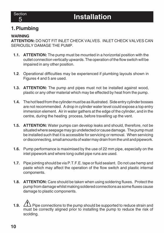
1. PlumbingWARNINGATTENTION: DO NOT FIT INLET CHECK VALVES. INLET CHECK VALVES CANSERIOUSLY DAMAGE THE PUMP.
1.1. ATTENTION: The pump must be mounted in a horizontal position with theoutlet connection vertically upwards. The operation of the flow switch will beimpaired in any other position.
1.2. Operational difficulties may be experienced if plumbing layouts shown inFigures 4 and 5 are used.
1.3. ATTENTION: The pump and pipes must not be installed against wood,plastic or any other material which may be effected by heat from the pump.
1.4. The hot feed from the cylinder must be as illustrated. Side entry cylinder bossesare not recommended. A drop in cylinder water level could expose a top entryimmersion element. Air in water gathers at the edge of the cylinder, and in thecentre, during the heating process, before travelling up the vent.
1.5. ATTENTION: Water pumps can develop leaks and should, therefore, not besituated where seepage may go undetected or cause damage. The pump mustbe installed such that it is accessible for servicing or removal. When servicingor disconnecting, small amounts of water may drain from the unit and pipework.
1.6. Pump performance is maximised by the use of 22 mm pipe, especially on theinlet pipework and where long outlet pipe runs are used.
1.7. Pipe jointing should be via P.T.F.E. tape or fluid sealant. Do not use hemp andpaste which may affect the operation of the flow switch and plastic internalcomponents.
1.8. ATTENTION: Care should be taken when using soldering fluxes. Protect thepump from damage whilst making soldered connections as some fluxes causedamage to plastic components.
1.9. Pipe connections to the pump should be supported to reduce strain andmust be correctly aligned prior to installing the pump to reduce the risk ofscolding.
11
1.11. Ensure no fluid drips onto the pump motor or its electrical connectionsduring installation, venting or operation as when the pump is energised thismay create a risk of electric shock.
1.12. Joint and assemble the adapter to the pump inlet. Do not overtighten theadapter.
1.13. Install a short length of 15mm pipe at the pump outlet, tighten thecompression joint. Push the flow switch onto this pipe (end marked Inlet first)ensuring that the flow switch is fitted vertically (See to Figure 7).
1.14. Place the pump on its resilient pad and complete the inlet and outlet pipework.
1.10. It is recommended that inlet/outlet isolation valves are fitted within closeproximity of the pump to permit isolation for servicing (See Figures 2 & 3).
12
B
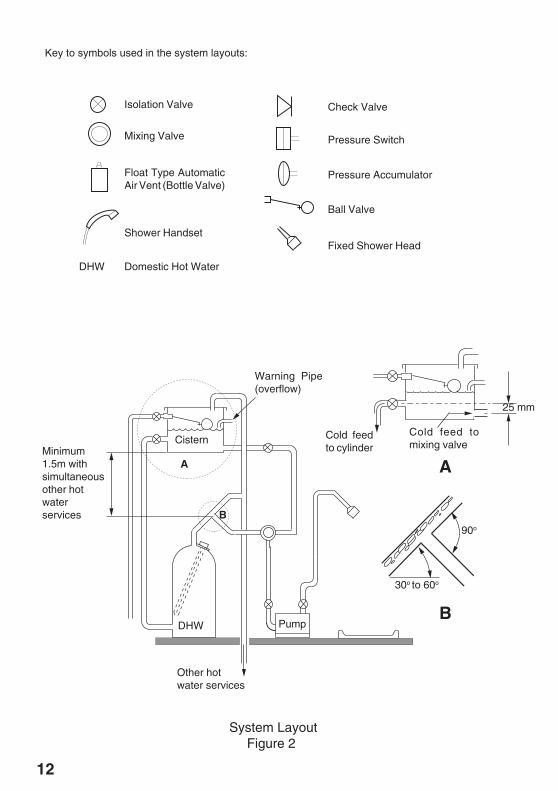
Minimum1.5m withsimultaneousother hotwaterservices
Cistern
Warning Pipe(overflow)
Cold feedto cylinder
Cold feed tomixing valve
25 mm
A
30o to 60o
90o
DHW Pump
Other hotwater services
B
A
Key to symbols used in the system layouts:
Isolation Valve
Mixing Valve
Float Type AutomaticAir Vent (Bottle Valve)
Shower Handset
Check Valve
Pressure Switch
Pressure Accumulator
Ball Valve
Fixed Shower Head
DHW Domestic Hot Water
Fault
System LayoutFigure 2
13
Cistern
DHW
Pump
Optional Check Valve
Other hot waterservices
System Layout with High Level PipeworkFigure 3
Other hot waterservices Pump
Cistern
DHW
Unsuitable System LayoutFigure 4
14
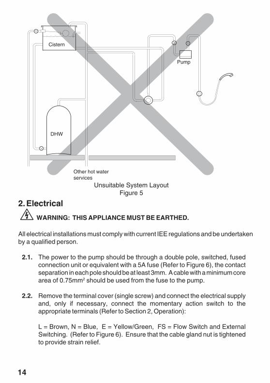
2. Electrical
WARNING: THIS APPLIANCE MUST BE EARTHED.
All electrical installations must comply with current IEE regulations and be undertakenby a qualified person.
2.1. The power to the pump should be through a double pole, switched, fusedconnection unit or equivalent with a 5A fuse (Refer to Figure 6), the contactseparation in each pole should be at least 3mm. A cable with a minimum corearea of 0.75mm2 should be used from the fuse to the pump.
2.2. Remove the terminal cover (single screw) and connect the electrical supplyand, only if necessary, connect the momentary action switch to theappropriate terminals (Refer to Section 2, Operation):
L = Brown, N = Blue, E = Yellow/Green, FS = Flow Switch and ExternalSwitching. (Refer to Figure 6). Ensure that the cable gland nut is tightenedto provide strain relief.
Other hot waterservices
DHW
Cistern
Pump
Unsuitable System LayoutFigure 5
15
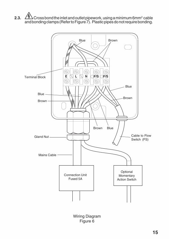
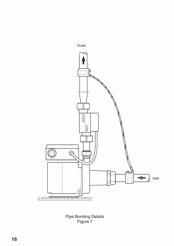
2.3. Cross bond the inlet and outlet pipework, using a minimum 6mm2 cableand bonding clamps (Refer to Figure 7). Plastic pipes do not require bonding.
Blue Brown
Terminal Block
Gland Nut
Mains Cable
Cable to FlowSwitch (FS)
E L N F/S
BrownBrown
Blue
Blue
Brown Blue
Connection UnitFused 5A
OptionalMomentary
Action Switch
F/S
Wiring DiagramFigure 6
16
Outlet
Inlet
Pipe Bonding DetailsFigure 7
17
Section
6 Commissioning
1. Commissioning
1.1. Proceed with caution due to the risk from hot water and scolding.
1.2. Ensure that the pump is electrically isolated.
1.3. Ensure that all the isolating valves are fully open and that the pump chamberis fully flooded.
THIS PUMP MUST NOT BE RUN DRY. IF IT IS, SEAL AND BEARINGDAMAGE MAY OCCUR.
1.4. Open the shower fully. Water should flow from the outlet under the pressureof gravity. Leave the outlet open for a short period of time to allow the air tobe expelled from the system. Turn off the shower and check the pump,shower and the interconnecting pipework for leaks.
1.5. If no water comes out of the outlet, then the system may be airlocked or theshower may be fitted in a negative head situation. Refer to Section 7,Maintenance: "Fault Diagnosis" or Section 2, Operation.
1.6. Switch on the power to the pump.
1.7. Open the shower valve and check that the pump has operated automatically.
1.8. The flow rate must be at least 1.4 l/min for the flow switch to operate.
1.9. If the pump is not operating correctly repeat the commissioning procedure,
18
Section
7 Maintenance
1. Fault Diagnosis
Read the section "Important Safety Information" first.
Providing the shower pump has been correctly installed and is operated in accordancewith the instructions contained in this guide, difficulties should not arise. If anymaintenance is required then it must be carried out by a competent tradesperson forwhom the fault diagnosis and maintenance instructions are provided. Before replacingany parts ensure that the underlying cause of the malfunction has been resolved.
1.1. Pump does not start
1.1.1. Check adequate gravity flow (1.4 l/m).
Isolate power and water and check:
1.1.2. Supply fuse, mains supply and the fused connection unit.
1.1.3. Free operation of the flow switch, fitted externally in the outlet verticalpipe of the pump, with the Inlet at the bottom.
1.2. Pump does not stop after the water flow has ceased
Isolate power and water and check:
1.2.1. Check that the flow switch is fitted correctly (Refer to Section 5,Installation).
1.2.2. Free movement of magnetic float within flow switch.
1.2.3. Any external switching connected operating correctly.
1.3. Pump operation occurs momentarily
If pump operation occurs momentarily, particularly when other hot waterservices that are not on the pumped circuit are used, or an on/off pulsatingoperation occurs when the shower is turned off, check:
19
1.3.2. Fit check valve onto pump outlet after flow switch to prevent watersurging in the pipe work. This may increase the pressure required tostart the pump (Refer to Figure 3).
1.4. Flow starts adequately and drops after a short time
Check:
1.4.1. Sufficient stored cold water.
1.4.2. Pipe work that is prone to air-locking should be rerouted to be selfventing when not in use. Float type Automatic Air Vents are, ingeneral, NOT advisable for pump inlet pipe work, as a negative pumppressure will allow air to be sucked in through Automatic Air Vents.The pressure at the desired vent position can approximately bedetermined using the Mira green book ‘A Guide to Domestic PumpedShower Systems’, to check whether it remains positive underdynamic conditions.
1.3.1. There are no air-locks in the pump outlet pipe work. These will causewater movement through the pump by compression of the air. Reroutethe pipe work or fit float type automatic air vents at air collection points.(Refer to Figure 3).
20
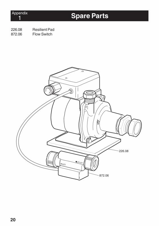
1 Spare PartsAppendix
226.08 Resilient Pad872.06 Flow Switch
226.08
872.06

21
Notes

22
Notes

23
Notes
24© Kohler Mira Limited November 2004
Mira ShowersKohler Mira LtdCromwell Road,Cheltenham GL52 5EP.
Mira is a registered trade mark ofKohler Mira Limited.The company reserves the right toalter product specifications withoutnotice.
Customer ServiceGuarantee of Quality
Within the guarantee period we will resolve defects, free ofcharge, by repairing or replacing parts or modules as we maychoose.
Not covered by this guarantee:Damage or defects arising from incorrect installation, improperuse or lack of maintenance, including build-up of limescale.
After Sales Service
Mira Showers guarantee products against any defect ofmaterials or workmanship for one year from the date ofpurchase (2 years for Mira Select and 3 years for Mira Excelranges).
What to do if something goes wrong
Should this not resolve the difficulty, simply contact ourCustomer Services who will give every assistance, and ifnecessary arrange for our service engineer to visit.If later the performance of your shower declines, consult thismanual to see whether simple home maintenance is required.Please call our Customer Services to talk the difficultythrough, request service under guarantee if applicable, ortake advantage of our comprehensive After-Sales service.
Payment should be made directly to the Service Engineer/Agent, using Visa, Access or a cheque supported by abanker’s card.
England, Scotland & Wales
Mira Showers Customer ServicesTelephone: 0870 241 08888.30am to 5pm Working days (4.30pm Fri)8.30 am to 12.30pm SaturdayE-mail: [email protected]: 01242 282595By Post: Cromwell Road
CheltenhamGloucester GL52 5EP
As part of our quality and training programme callsmay be recorded or monitored
For Customers in Northern IrelandWm H Leech & Son LtdTelephone: 028 9044 9257 – Mon to Fri 9 am-5pmFax: 028 9044 9234 – 24 hoursPost: Maryland Industrial Estate
Ballygowan RoadMoneyreagh, Co DownBT23 6BL
For Customers in Republic of IrelandModern Plant LtdTelephone: Dublin 01 4591344 - Mon to Fri 9am to 5pmFax: Dublin 01 4592329 – 24 hoursPost: Otter House
Naas RoadClondalkinDublin 22
To validate the guarantee, please return your completedregistration card.
To be free of charge, service work must only be undertakenby Mira Showers or our approved agents in Northern Irelandand Republic of Ireland.Service under this guarantee does not affect the expirydate. The guarantee on any exchanged parts or productends when the normal product guarantee period expires.
Damage or defects if the product is taken apart, repaired ormodified by any person not authorised by Mira Showers orour approved agents.
This guarantee is in addition to your statutory and otherlegal rights.
Before using your showerPlease take the time to read and understand theoperating and safety instructions detailed in this manual.
If when you first use your shower it doesn’t functioncorrectly, first contact your installer to check that installationand commissioning are satisfactory and in accordance withthe instructions in this manual. We are on-hand to offer youor your installer any advice you may need.
Spare Parts
Our Customer Services Team is comprehensively trainedto provide every assistance you may need: help andadvice, spare parts or a service visit.
We maintain an extensive stock of spares, and aim tohave functional parts available for ten years from the dateof final manufacture of the product.Spares can be purchased from approved stockists ormerchants (locations on request) or direct from CustomerServices.
Note! In the interests of safety, spares requiring exposureto mains voltage can only be sent to competent persons.
Spares direct will normally be despatched within twoworking days. Payment can be made by Visa or Accessat the time of ordering. Should payment by cheque bepreferred a proforma invoice will be sent.
Our Service Force is available to provide a quality serviceat a reasonable cost. You will have the assurance of a Miratrained engineer/agent, genuine Mira spares – and a 12month guarantee on the repair.
Service
To contact us:
P2615/9 Part No. 6479504