Shower Controls - Bathroom Academy · Introduction This guide provides information on the types of...
23
The Bathroom Academy Strategic Professionals in partnership with Shower Controls
Transcript of Shower Controls - Bathroom Academy · Introduction This guide provides information on the types of...

1 Industry Guide to Shower Controls Issue 4/11 Copyright 2015 Bathroom Manufacturers Association
The Bathroom AcademyStrategic Professionals
in partnership with
Shower Controls
2 Industry Guide to Shower Controls Issue 4/11 Copyright 2015 Bathroom Manufacturers Association
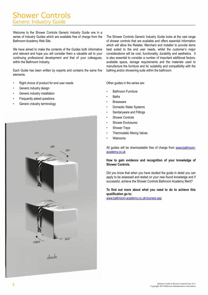
Shower ControlsGeneric Industry Guide
Welcome to the Shower Controls Generic Industry Guide one in a series of Industry Guides which are available free of charge from the Bathroom Academy Web Site.
We have aimed to make the contents of the Guides both informative and relevant and hope you will consider them a valuable aid to your continuing professional development and that of your colleagues, within the Bathroom Industry.
Each Guide has been written by experts and contains the same five elements:
• Right choice of product for end user needs• Generic industry design• Generic industry installation• Frequently asked questions• Generic industry terminology
The Shower Controls Generic Industry Guide looks at the vast range of shower controls that are available and offers essential information which will allow the Retailer, Merchant and Installer to provide items best suited to the end user needs, whilst the customer’s major considerations will be cost, functionality, durability and aesthetics. It is also essential to consider a number of important additional factors; available space, storage requirements and the materials used to manufacture the furniture and its’ suitability and compatibility with the bathing and/or showering suite within the bathroom.
Other guides in the series are:
• Bathroom Furniture• Baths• Brassware• Domestic Water Systems• Sanitaryware and Fittings• Shower Controls• Shower Enclosures• Shower Trays• Thermostatic Mixing Valves• Wetrooms
All guides will be downloadable free of charge from www.bathroom-academy.co.uk
How to gain evidence and recognition of your knowledge of Shower Controls.
Did you know that when you have studied the guide in detail you can apply to be assessed and tested on your new found knowledge and if successful, achieve the Shower Controls Bathroom Academy Merit?
To find out more about what you need to do to achieve this qualification go to:www.bathroom-academy.co.uk/courses.asp

3 Industry Guide to Shower Controls Issue 4/11 Copyright 2015 Bathroom Manufacturers Association
Introduction
Water Efficiency Product Design
Section 1Domestic Mixing Valves and Pumped Shower Products
Types
Operating Principles - Styles of mixing valve controls - Manual mixing valves - Venturi boost mixing valves - Pressure compensating mixing valves - Thermostatic mixing valves - Bi-metal coil - Digital electronic mixing unit
Mixer Shower Flow Rate Characteristics - Low pressure mixing valves - High pressure mixing valves - General purpose mixing valves
Mixing Valve Standards
Commissioning Requirements
Common Site Problems - Causes and remedies
Frequently Asked Questions
Section 2Instantaneous Electric Showers
Operating Principles
Plumbing Requirements - Mains fed showers
General Plumbing Guidance
Electrical Requirements
Commissioning Requirements
Common Site Problems - Causes and remedies
Frequently Asked Questions Section 3Industry Terminology
Section 4References
Contents

IntroductionThis guide provides information on the types of shower controls available, shower performance, installation and commissioning requirements.
Electric Instantaneous ShowersAn electric instantaneous shower connects to a cold water supply only. Models are available for both mains and cistern fed water supplies. Elements in the shower (similar to those in a kettle) heat the water as it is used. There is no waste from storing a large volume of hot water in a cylinder.
Mixing Valves and Pumped Shower ProductsA shower controlled by a mixing valve connected to the hot and cold water system in the property. As the name implies it mixes the hot and cold supplies to achieve a preferred showering temperature. The flow rate from such showers is dependent on the type of hot water system in the property and the available supply pressures. They generally provide higher flow rates than electric showers.
A shower consisting of a mixing valve and pump is generally referred to as a power shower.
Where the hot and cold water supplies in a property are fed from a cold water cistern and hot water cylinder the pressure available may be low. To improve the shower performance a pump can be fitted either to boost pressure and flow to the mixing valve (twin impeller pump) or to boost pressure and flow after the water has been mixed (single impeller pump).
Benefits of each shower type:
Electric Showers
• Economically heats the water as it is used, no waste from heating a cylinder of water• Average of five showers can be taken for the same cost as filling a bath• Easy to plumb in, requires a cold water supply only • Thermostatic models available
Mixing Valves
• Usually provide higher flow rates than electric showers• Ideal for homes with readily available hot water• Thermostatic models available • Options available for both low and high pressure water systems
Power Showers
• The ultimate in exhilarating shower performance from gravity fed water supplies
• Similar to a mixing valve based shower but with the added benefit of a pump to boost the flow
• Option of integral pumped units or separate pump and mixing valve• Thermostatic models available.
Choosing the right productIt is important to note that before specifying any shower product it is necessary to establish the type of hot and cold water system in the property and the customers’ expectations in respect of the product performance. For this reason, we strongly recommend you also study the Domestic Water Systems Generic Industry Guide downloadable free of charge from www.bathroom-academy.co.uk
4 Industry Guide to Shower Controls Issue 4/11 Copyright 2015 Bathroom Manufacturers Association

Water Efficiency Product DesignWater saving and the showering experience do not tend to go together. User behaviour plays a pivotal role as more water can be saved by reducing the time spent in the shower against reducing the water flow. However, careful selection of shower equipment can ensure that the shower provides an adequate performance without using as much water. For traditional low pressure plumbing systems the choice of shower is typically either an electric shower (fed from cold mains only) or a mechanical, digital or thermostatic mixing valve designed for use on balanced low pressure supplies. The advantage with these types of installation is that they will typically provide economy flow rates by their very design. A gravity fed (low pressure) mixer shower is unlikely to deliver in excess of 8L per minute to the user. Showers designed for low pressure systems often have flexible hoses with larger internal bore sizes - say 10mm – while high pressure shower systems typically use flexible hoses with bores of around 8mm. Reduced flow through low pressure systems can be achieved if the flexible hose is replaced for one which is a narrower bore than the original supplied.
Generally electric showers are seen as the ultimate in water saving, as they only heat the water needed and are therefore Eco by default. The majority of designs deliver on average 6L. However electric showers, as they instantaneously heat the water that is being used, have flow rates that vary on a seasonal basis. The variation is caused by the temperature of the incoming water – the warmer this is the less the electric shower is required to heat it to the desired temperature. Flow rates therefore vary from winter to summer in the region of 3 to 12L per minute. Care should be taken not to insert flow restrictors in the incoming water pipework to reduce the water flow from the shower in an attempt to save water. This can be dangerous if insufficient water is flowing over the electric heating elements, as they may overheat. The manufacturers’ installation instructions must always be adhered to.
Shower heads take the blended hot and cold water from the mixing valve or electric shower unit and create a spray of water, available in a variety of patterns. Aerated shower heads are available in the marketplace, where water is mixed with air in the shower head to create an invigorating spray but with up to 75% less water than a standard shower head. They are predominantly designed for high pressure systems.
Water and energy (for heating hot water) may be saved by fitting a shower outlet flow limiter. A selection of water flow limiters are available in a variety of sizes that will lessen the water flow without diminishing the quality of the shower experience. Care should be taken in applying these and advice sought from manufacturers as to which can be fitted to suit the products being used.
5 Industry Guide to Shower Controls Issue 4/11 Copyright 2015 Bathroom Manufacturers Association

Section 1Domestic Mixing Valves and Pumped Shower Products
Types
A wide range of mixing valve shower products are available, all of which are constructed around a mixing valve, which as the name implies mixes the domestic hot and cold water supplies to achieve a preferred showering temperature. The types of mixing valves and pumped shower products available are as follows (with riser kits and heads often supplied separately):
• Single point built in (recessed) mixing valve with riser kit or fixed head.• Single point exposed (surface-mounted) bar shower mixing valve with
riser kit or fixed head.• Shower panels and installed body jet systems.• Integral pumped power shower.• Digital shower.• Bath shower mixing valve.
Operating Principles
Styles of Mixing Valve ControlsAll shower mixing valves have a means of turning the flow on and off and regulating the hot and cold water supplies to establish a preferred showering temperature, but only some provide variable flow settings.
Flow and temperature adjustment can be achieved in the following ways:
Sequential ControlA single control knob initiates flow at a cold setting, progressive rotation of the control increases the temperature setting.
Single Lever ControlA single lever performs two functions. Moving the control up and down regulates the flow, moving it to the left and right adjusts the temperature setting.Concentric ControlAn outer control is turned to initiate and adjust the flow of water, an inner control is turned to the left or right to adjust temperature.
Dual ControlTwo separate controls are provided one for flow control, the other for adjusting the temperature.
Digital & Remote TechnologyAn electronic control panel mounted in or around the showering area provides separate controls for flow and temperature settings. A processor box sited remotely from the shower area adjusts the flow and temperature relative to the settings selected on the control panel.
Temperature Stability CharacteristicsThe ability of a shower control to maintain the selected temperature, when pressure and temperature changes occur in the hot and cold supplies, depends on its internal construction.
Methods of ConstructionMixing valves are constructed as either:
1. A manual mixing valve.2. A venturi boost mixing valve.3. A pressure compensating (balancing) mixing valve.4. A thermostatic mixing valve.5. A digital electronic mixing unit.
Manual Mixing ValvesThe requirement of any mixing valve is that it blends hot and cold water to achieve a comfortable shower temperature.
For manual mixing valves this can be achieved in a variety of ways e.g. the mixing chamber can contain two ceramic or plastic discs, one placed on top of the other. Moving one disc over the other regulates the flow of hot and cold water through flow paths (holes) cut into the discs. Closing off an area of the disc to restrict the hot water automatically increases the area through which cold water is flowing.
Once set, the temperature control mechanism in a manual mixing valve remains fixed and does not automatically adjust if a change in supply pressure or temperature occurs whilst showering.
A manual mixing valve is therefore wholly reliant on the supply of hot and cold water remaining at:
a) A balanced pressureb) A stable temperature
if showering temperature is to remain constant.
Most plumbing systems are prone to pressure changes occurring whilst showering.
Should there be a total loss of either the hot or cold water supply then a manual mixing valve will not shut off the remaining supply.
Some manual mixing valves have an adjustable stop mechanism (to prevent the temperature control being turned past a comfortable setting) this should be set according to the supply conditions present on each installation.Whilst manual mixing valves are produced for both high and low pressure systems, they are best suited to balanced hot and cold supplies and systems where the hot water supply temperature remains constant.
Some manual mixing valves can also incorporate a diverter enabling connection to a secondary outlet.
6 Industry Guide to Shower Controls Issue 4/11 Copyright 2015 Bathroom Manufacturers Association

Venturi Boost Mixing ValvesUnlike most mixing valves that benefit from relatively balanced hot and cold supplies the venturi mixing valve is specifically designed to work on unbalanced supplies of mains cold water and gravity fed hot water.
For correct operation of this type of mixing valve the mains cold water pressure must be at the minimum running pressure specified by the manufacturer, usually around 1.5 bar. In some cases where water pressure is excessive a pressure reducing valve needs to be fitted to limit pressure to 3 bar.
A venturi mixing valve uses the extra pressure (energy) of the cold water to increase the flow rate of hot water significantly, using the venturi principle.
As cold water passes through the specially shaped venturi its velocity increases. This causes the cold water pressure to be reduced. It is at a minimum as the water passes through the narrowest part of the venturi and it is at this point where the hot water is drawn into the cold and mixed. As the mixed water leaves the venturi its pressure reverts to a level almost as high as it was before, thereby providing a forceful shower.
A needle valve is incorporated to act as a throttle in order to adjust the operation of the mixing valve.
It is essential that the whole system, particularly the hot water distribution pipework is installed to give minimum pressure loss.
Correctly installed, a venturi mixing valve will provide a reasonably stable showering temperature, even if the cold water pressure varies e.g. when taps are turned on elsewhere in the property. However, to provide protection from scalding in the event of cold water failure, a thermal shutdown device is incorporated, this reduces water flow to a trickle.
Note that such mixing valves do not shut off the flow completely, this is to warn the user that the mixer is not actually turned off and that water might recommence flowing once the cold water supply is restored.
To comply with Water Regulations, check valves are required on both the hot and cold supplies to ensure no backflow can occur.
Also pipework in the installation must not contain any unnecessary flow restrictions that could upset the ratio of hot and cold water and thus reduce the mixed water temperature.
Pressure Compensating Mixing ValvesThis type of mixing valve provides greater temperature stability compared to a manual mixing valve. Some are designed for both low and high pressure systems others for high pressure systems only.
Such mixing valves are produced with either sequential or dual controls to set the flow and temperature.
a) Sequential controlStarting the shower initially at a cold setting, turning the control progressively increases showering temperature whilst maintaining a relatively fixed flow rate.
Once temperature is set a pressure balanced diaphragm or alternatively stabilising core reacts to changes in water pressure and maintains the correct mix of hot and cold water.
b) Dual controlDual control pressure compensating mixing valves have a separate flow control (tap) and temperature control (pressure compensating) mechanism.
The pressure compensating mechanism in some consists of a metal shuttle, which moves backwards and forwards inside a tube. The shuttle regulates the hot and cold water flowing through the mixer. If there is a drop in pressure in one of the supplies the shuttle is moved inside the plastic tube thereby increasing the flow path on the reduced pressure side, whilst at the same time restricting the flow path on the high pressure side.
Pressure compensating mixing valves maintain showering temperature when pressure changes occur in the supplies. However they cannot react to changes in supply temperature, therefore they should only be installed on hot water systems that maintain a stable delivery temperature.
Thermostatic Mixing ValvesThermostatic mixing valves afford optimum control of showering temperature.
The maximum temperature that can be selected may be factory set by the manufacturer.
Where this is the case, the maximum showering temperature will normally be set between 38°C and 43°C. There will usually be some means of internal adjustment or an external push button temperature override, allowing selection of hotter settings.
Valves that have been factory set are calibrated on the basis that water entering the mixer will be approximately 55°C hot and 15°C cold. Following installation a minor adjustment of the temperature stop may be necessary to suit the available supply conditions.
Thermostatic mixing valves maintain the set temperature when pressure or temperature changes occur in the water supplies. They also afford the added safeguard of shutting off flow should there be a total loss of either supply.
A variety of materials are used in construction, which includes plastics, metals and ceramics, in one or more combinations.
Having set a showering temperature a thermostatic device in the mixing valve maintains that temperature.
The most common thermostatic devices in use are:
a) The wax capsule device.b) The bi-metal coil.c) Digital electronic mixing unit. Wax capsule principleA copper capsule containing a mixture of wax and fine metal particles is situated in the mixed water section of the valve. Heat transfer in the capsule causes the wax to expand, if cooled the wax contracts. As the wax expands it forces a metal piston out of the top of the capsule. This force is transferred on to a shuttle which moves forward and backward thus proportioning the amount of hot and cold water entering the valve. Typically the movement of the shuttle, when the wax contracts, is made by a spring that acts on the shuttle as the wax capsule is only able to directly move the shuttle in one direction i.e. as the capsule expands.
The wax capsule, in combination with the spring, continually move the shuttle to proportion that mix of hot and cold water thus maintaining a stable temperature.
The wax capsule will attempt to maintain this stable temperature by compensating for inlet water temperature and pressure changes.
7 Industry Guide to Shower Controls Issue 4/11 Copyright 2015 Bathroom Manufacturers Association

Bi-Metal Coil PrincipleIn this case a bi-metallic coil is situated in the mixed water. When the water flowing over it changes in temperature the coil expands and contracts. This movement is used to alter the position of a shuttle, which is attached to the coil. As the shuttle moves backwards and forwards it regulates the amount of hot and cold water entering the mixing chamber.
Digital Electronic Mixing UnitThe hot and cold water supplies are electronically controlled to provide a desired temperature and flow at the shower. This can be by adjustment of separate proportioning valves and pumps or by motorised control of a mixing valve.
Whichever method used the water temperature is maintained to provide thermostatic performance at the showerhead.
Various types of thermostatic mixing valves are available ie:
Concealed with One OutletOne outlet mixer valve with 2 handles, providing a low pressure option if only one outlet is required to be operated. The top handle is for water flow and the bottom handle is for water temperature.
Concealed with Two OutletsTwo outlet mixer valve with 2 handles, providing control of 2 separate outlets. The top handle controls water flow via a diverter between the 2 outlets and the bottom handle controls water temperature.
Three Control with Two Independent outletsThree control mixer valve with 2 independent outlets, which can be used either simultaneously or separately. A low pressure alternative suitable for addition of, for example, a hand shower to complement the existing overhead shower.
Mixer Shower Flow Rate CharacteristicsThe flow rate from a mixer shower is dependent on the following factors:
• The available water pressures.
• Pressure loss in pipes and fittings before the mixing valve.
• Internal restrictions within the mixing valve.
• Restrictions present in the shower hose and showerhead.
It is important to ensure that water supply pressures meet the specified running and static pressure requirements for the product i.e. is the mixing valve specified for low or high pressure applications?
Low Pressure (LP) Mixing ValvesLow pressure mixing valves are designed for use on gravity fed systems where pressures are between 0.1 to 1 bar.
In domestic premises the cold water cistern feeding the hot water cylinder is usually in the loft where the bottom of the cistern is approximately 1 metre above the showerhead. This equates to 0.1 bar pressure at the showerhead.
There can be a number of restrictions within a gravity system i.e. elbow fittings. These restrictions further reduce operating
pressure. To achieve the required minimum running pressure of 0.1 bar at the valve, it may be necessary to raise the cold water cistern or increase the size of pipe and fittings to reduce frictional losses.
Because of the difficulties involved in raising a cold water cistern it has become more common to increase gravity system pressure by installing a booster pump.
If the minimum specified running pressure is achieved at the mixing valve, flow rates should be near to those quoted by the manufacturer. Performance will vary from one mixer shower to another, as restrictions within each valve and showerhead will differ.
High Pressure (HP) Mixing ValvesSome valves are designed for use on pumped gravity and mains fed water systems only, where the minimum pressure is 1 bar.
High pressure valves are generally designed to be more restrictive to provide better control of flow and temperature at the higher pressures. Flow rates in excess of 20L per minute can be achieved depending on available water pressure and mixing valve design.
General Purpose (GP) Mixing ValvesSome mixing valves are designed to work on all types of plumbing system i.e. balanced gravity systems from 0.1 to 1 bar and pressurised systems above 1 bar. Some GP mixing valves are specified for connection to mains fed cold water and gravity fed hot water. However, it should be noted that an imbalance of pressure outside the ratio stated by the manufacturer could give rise to fluctuations in showering temperature. Also to comply with water regulations check valves must be present in both supplies to prevent cross flow through the mixing valve.
Again depending on available pressure and mixing valve construction, high flow rates can be achieved.
Mixing Valve StandardsStandards for Thermostatic Mixing Valves:
BS EN 1111 (HP) 1287 (LP) – TMV Type 2 Mixing ValvesThese standards are intended to define the requirements for domestic Thermostatic Mixing Valves.
BS EN 1111 The standard for high pressure mixing valves specified for system pressures greater than 1 bar.
8 Industry Guide to Shower Controls Issue 4/11 Copyright 2015 Bathroom Manufacturers Association

BS EN 1287 Covers low pressure mixing valves (0.1 – 1 bar).
Flow Rate Test (Open Outlet)Low pressure valves should provide between 6 and 7.5 L/min at 0.1 bar.
High pressure valves should provide at least 12 L/min at 3 bar.
Various Pressure TestsThe valve has to withstand a range of pressure tests and remain effective without leakage or distortion of the body.
The mechanism and seals etc. are also subjected to a pressure test of 16 bar as a maximum condition and 0.2 bar as a minimum condition.
Temperature Control SensitivityThe temperature control has to provide a sensitivity of 8°C over a minimum movement of 12mm in the range 34°C - 42°C.
Temperature Stability under Changing Inlet Pressure ConditionsThe valve has to maintain the blend temperature to ± 2°C with a 50% drop in cold water supply i.e. from 0.2 bar down to 0.1 bar.
Temperature Stability under Changing Inlet Temperature ConditionsThe valve has to maintain the blend temperature to 2°C with a 10°C increase/decrease in hot water temperature.
Thermal Shut-OffThe valve will shut down and only allow a volume of 0.3L of water to flow during a period of 30 seconds after cold water isolation. Blend temperature to recover to ± 2°C of set temperature after supply restoration.
Temperature Stability at Reduced FlowratesBlend temperature must remain within - 2°C of set temperature when flow from the outlet is reduced.
Department of Health (DH) DO8 – TMV Type 3 Mixing Valve.In 1997, an enhanced thermostatic mixing valve specification was introduced for the DH, this being specification DO8.Thermostatic mixing valves conforming to this specification are recognised as providing the required safeguards against scalding for patients and residents in healthcare premises.
Independent testing of valves is carried out by NSF-WRc to ensure valves meet the stringent requirements of the DO8 specification.
Mixing valves that comply with DO8 can gain certification under NSF-WRc’s BuildCert Scheme as Type 3 thermostatic mixing valves, these are deemed suitable for use in all applications where the risk of scalding must be reduced.
Type 3 TMVs are required for the delivery of safe hot water temperatures to a variety of applications i.e. bidets, washbasins, showers and baths at both low and high water pressures.
A Type 3 TMV mixer’s suitability for use is indicated by designated abbreviations these are as follows:
Application Abbreviated Designations Mixed water temperature °CBidet HP-B, BE - LP-B, BE 38 maxShower HP-S, SE - LP-S, SE 41 maxWashbasin HP-W, WE - LP- W, WE 41 maxBath (44°C fill) HP-T44 - LP T44 44 maxBath (46°C fill) HP- T46 - LP-T46 46 max
Operating Pressure Range Type 3 TMV High Pressure Type 3 TMV Low PressureMaximum static pressure - bar 10 10Flow pressure, hot and cold - bar 1 to 5 0.2 to 1Hot supply temperature - ˚C 52 to 65 52 to 65Cold supply - ˚C 5 to 20 5 to 20
Valves operating outside of these conditions cannot be guaranteed to operate as Type 3 TMV.
A valve can only be used for a particular application if it has been assigned the appropriate designation, e.g. LP-B, LP-W, LP-S mixing valve.
In this example, the valve can only be used as a low pressure mixing valve for a bidet, washbasin or shower. It could not be used as a low pressure, bath-mixing valve or used on high pressure.
To ensure TMV 3 performance is maintained, periodic performance checks must be carried out.
9 Industry Guide to Shower Controls Issue 4/11 Copyright 2015 Bathroom Manufacturers Association

Commissioning Requirements
1. It is essential to flush out debris from the hot and cold supplies in order to prevent damage to the working parts of a mixing valve. Wherever possible this should be done prior to making final connections to the valve. If for any reason pipes cannot be flushed prior to making final connections then a flushing cartridge may be supplied with the product. Failure to flush supplies can result in blocked filters or damage to valve components.
2. The recommended hot water temperature for mixing valves is between 55° and 65°C.
The water heating appliance must be capable of supplying at least 52°C at flow rates between 3 and 8L/minute.
Mixing valves must not be subjected to temperatures above 80°C as internal components may be damaged.
Manufacturers’ specification details should always be referenced.
3. In most cases the hot and cold water pressures must be nominally equal and within the mixer valves specified operating range i.e. low pressure 0.1 bar to 1 bar, high pressure greater than 1 bar running pressure.
4. If pressures exceed the specified maximum running pressure then a Pressure Reducing Valve must be fitted. In domestic installations this is best set to around 3.5 bar running pressure. Supplies must remain relatively balanced.
5. In the case of thermostatic mixing valves, depending on the customer’s requirements and variations in hot water supply temperatures, it may be necessary to adjust the maximum temperature stop from its factory set position. Before advising on adjustment, always refer to the commissioning section in the relevant fitting instructions.
Common Site Problems - Causes and RemediesMost common problems that arise on mixer shower products can be resolved by conducting a few simple checks:
1. No Water Flowing
2. Water too Cold /Cool
3. Water too Hot
4. Poor Flow From Showerhead
1. No Water FlowingHas water been turned on fully at the isolating valves?
Is the cold water cistern at least 1 metre above the showerhead?
Have inlet elbows/filters been checked for blockages?
Is there an air lock in the hot or cold supply?
2. Water too Cold/CoolIs the domestic hot water hot enough? Check at taps for approx. 55 - 60ºC.
Has the mixing valve been connected correctly to gravity hot and cold (if mains cold re-plumb to cold water cistern)?
Is the temperature acceptable by pressing the temperature override button (increasing to a higher number)?
3. Water too HotIs cold water isolating valve fully open?
Has cold inlet been checked for blockage?
4. Poor Flow from ShowerheadHas spray plate been de-scaled?
Are isolating valves fully open?
Have inlet filters - check valves – flow limiters been checked for any blockages?
Is the cold water cistern a minimum of 1 metre above showerhead?
Is there an air lock in the hot or cold supply?
10 Industry Guide to Shower Controls Issue 4/11 Copyright 2015 Bathroom Manufacturers Association

Can a power shower unit be fitted to the mains cold water supply?
A power shower unit contains a pump. The construction of the pump is such that it can only accept a low pressure gravity (cistern fed) supply. Connecting the shower to the mains will subject the pump to excess pressure and result in damage to the pump and leakage from the unit. Water Regulations prohibit the connection of this type of pump to the mains water supply.
Can an integral power shower be installed onto a combi-boiler?
All integral power showers incorporate a pump and mixing valve, which can only be connected to low pressure gravity supplies. Connecting to a high pres-sure mains fed combi-boiler will damage the shower unit. This combination also contravenes the Water Regulations.
I am fitting a shower panel and the hot supply is from a combi-boiler. How can I be sure there will be enough flow from the combi to satisfy customer needs?
The performance of a combi-boiler is determined by its kW rating and tem-perature can change dependent on season. The boiler specification literature should provide flow rate figures for a given temperature rise, enabling hot water output throughout the year to be established.
As a rough guide each function on a shower panel i.e. the overhead spray, hand held spray and body jets can each deliver from 8 to 14L per minute, depending on supply pressure. To satisfy two functions simultaneously effectively requires around 13L per minute.
If you are fitting a shower panel to gravity fed water supplies you will need to increase supply pressures by installing a twin impeller pump. Depending on the model of the shower panel and customer preferences the pump should be rated at 1.5 to 4 bar running pressure.
How do you determine the pressure you will get to a showerhead when a mixer shower is connected to a gravity supply?
The principle is that for every 1 metre head of water, (as measured from the base of the cold water cistern to the top of the showerhead) there will be a pres-sure in the showerhead of 0.1 bar. This is a theoretical pressure as restrictions within pipe fittings and the shower mixing valve will reduce the pressure slightly.
Providing only minimal restrictions are present in the supplies and mixing valve the additional measurement (height) of water within the cistern will usually com-pensate for pressure losses in the supplies.
It can be seen that a shower requiring 1 bar minimum operating pressure would need to be connected to a cistern located 10 metres above the showerhead.
Is it acceptable to install two power showers onto a 115L (25 gallon) cold water cistern if they are going to be used simultaneously?
When two power showers are in operation simultaneously they can draw around 30L (6 gallons) per minute from the cold water cistern. If the cold water entering the cistern through the float operated valve is less than this amount then the level of water in the cistern may fall to the level of the connections to the showers. Air will then be drawn into the supplies, adversely affecting shower performance and potentially damaging the pumps.
It is advisable to increase the cistern capacity to at least 230L (50 gallons) and check that the filling rate of the cistern is adequate to cater for all outlets that are likely to be in use simultaneously.
Do I need to use a cylinder flange when installing a mixer or power shower?
Most leading shower manufacturers agree it is not necessary to use cylinder flanges when installing a single domestic power shower. T'ing into the inclined section of pipe from the top of the cylinder is the preferred method of connec-tion. Providing the 'T' is pointing down, air released from the heated water in the cylinder will bypass the 'T' and escape out of the expansion pipe.
If it is not possible to fit the 'T' in this fashion it can be installed in the falling supply to other outlets, providing it is below the expansion pipe T and is the first take off point before other taps.
Can a mixing valve be installed to unbalanced supplies of mains fed cold water and gravity fed hot water?
Water Regulations permit the connection of mixing taps and shower mixing valves to mains fed cold water and gravity fed hot water, providing there is a check valve in both supplies to prevent crossflow. Check with the manufac-turers’ installation instructions that the product can be used to mix mains and gravity supplies.
I have a Thermal Store hot water system in my property. How many mixer showers can be fed from one of these appliances?
The output from a thermal store unit depends on its size (stored volume), heat transfer capability and the water pressure entering the unit. Some are only capable of delivering sufficient hot water to one mixer shower whereas others can supply 3 or 4 showers simultaneously. Always check before selecting any shower that the capacity of the heating appliance is compatible with the shower and required usage.
I have fitted a thermostatic mixer shower to a combi-boiler system only to find the shower temperature is fluctuating, I thought a thermostatic mixing valve was supposed to remain at a constant temperature.
The most common reason for this symptom is when the combi-boiler is not fully modulating (i.e. the gas flame is not regulated in sympathy with the flow of water through the heat exchange unit) and is therefore not maintaining stable hot water temperature to the shower.
As hot water entering the shower increases in temperature a thermostatic mechanism will adjust to restrict hot water entering the valve. In turn flow through the boiler is reduced and the temperature reaches a point where a thermostat switches off the burner. Water temperature will then reduce before the thermostat resets, this will result in the shower constantly cycling between hot and cool.
The flow from my mixer shower is less than I expected, what is the usual performance of a shower on a gravity system?
Flow rate from mixer showers varies depending on the available head of water and restrictions within the supply and valve. To ensure optimum performance from gravity fed mixer showers the following guidance should be followed.
• Use as few 90°elbows as possible and where possible use pulled bends• Use full way lever or gate valves, do not fit restrictive stop taps or 1/4 turn
service valves• Follow manufacturer recommendations regarding pipe size• Ensure the mixing valve is specified for low pressure application• Always flush out pipes before connecting to avoid debris blocking inlet
filters.
Section 1Frequently Asked Questions
11 Industry Guide to Shower Controls Issue 4/11 Copyright 2015 Bathroom Manufacturers Association

I have been asked to install a thermostatic mixer shower in a care home, are there any special requirements I should be aware of for this type of situation?
Most care homes are now following DH guidance on the delivery of safe hot water temperature to outlets.This means a care home may insist on a Type 3 - mixing valve being fitted, which carries BuildCert or similar certification and meets the DH DO8 specification for mixing valves.
In addition to the shower, appliances such as basins, bidets and baths will also most certainly require thermostatic control of the hot water outlets.
My thermostatic mixer shower is supplied from a combi-boiler and I cannot achieve a hot enough showering temperature. What could be the problem ?
The most common causes of this symptom are:
• The flow of water through the shower is too great and the boiler is unable to heat the water to the required temperature. Isolating the cold supply and measur-ing the hot water flow and temperature through the mixing valve on its maximum hot setting should establish whether this is the case. If so it will be necessary to fit some form of flow limiting device on the inlet or outlet of the shower.
• A blockage has occurred in the hot supply thereby limiting the amount of hot water available to mix with the cold. Turning the temperature control of the shower to fully hot then fully cold should provide an indication of whether the hot and cold supply entering the mixing valve are of equal volume.
I am looking to install a mixer shower onto a thermal store hot water system. Can I fit a pressure compensating mixer shower to this type of system?
Pressure compensating valves can be specified for this type of high pressure system. A pressure compensating mixer shower is designed to maintain the set showering temperature when a pressure change occurs in either the hot or cold supply i.e. when another tap is turned on in the property. However this type of mixer shower does not respond to any changes that occur in the hot water supply temperature.
Providing the thermal store unit is capable of maintaining a constant water temperature when other taps are operated, then a pressure compensating valve can maintain a comfortable showering temperature. Where there are noticeable fluctuations in thermal store domestic hot water temperature then a thermostatic mixing valve should be specified.
Can I use one twin ended pump to supply water to three mixer showers?
It is possible to supply a number of mixer showers from one pump providing the following guidelines are followed:• The pump must be suitably rated to provide the flow and pressure that will cater for simultaneous shower use. Example: Three showers are required to deliver 10L per minute at a minimum delivery pressure of 1 bar when operated individually. Therefore a pump capable of delivering 30L per minute at 1 bar running pressure is required.• If a number of showers are supplied by one pump, supply pressures will fluctuate when showers are being operated simultaneously.• Thermostatic Mixing Showers should be fitted to ensure a stable showering temperature is maintained.
12 Industry Guide to Shower Controls Issue 4/11 Copyright 2015 Bathroom Manufacturers Association

Section 2Instantaneous Electric Showers
Operating Principles
All electric showers heat cold water instantly as it flows over one or more electric heating elements in the unit. The main advantage of this type of shower is that it only heats water as it is used, so there is no waste from storing a cylinder full of hot water.
A wide range of electric showers is available. Apart from unique operating features for each model electric showers fall into three distinct types.
a) Temperature Stabilised Electric Shower
This type of electric shower incorporates a mechanical pressure compensating (flow stabilising) valve. When pressure fluctuations occur in the mains water supply i.e. when taps elsewhere are turned on, the stabilising valve automatically adjusts to maintain the selected flow through the unit. If the volume of water passing over the heating elements is unchanged then the showering temperature will remain stable. Typically showering temperature is maintained to ± 5°C when pressure changes occur.
b) Thermostatic Electric Showers
Thermostatic showers provide enhanced temperature stability.
Some incorporate sophisticated electronic controls to monitor and respond to sudden changes in site conditions others use mechanical thermostat technology similar to that found in thermostatic mixer showers. Temperature is generally maintained between 1 and 2°C of the selected temperature when water pressure, voltage or ambient water temperature changes occur.
Some models also incorporate a maximum temperature stop to ensure that a preferred temperature cannot be exceeded.
c) Pumped Electric Showers
Some models of electric shower have their own in-built pump. This type of unit must be connected to a dedicated supply from a cold water cistern. They must not be connected to the mains cold water supply.
Having its own dedicated gravity fed supply this type of shower is unaffected by pressure fluctuations occurring in the mains water supply, therefore showering temperature is unaffected.
A temperature stabilised or thermostatic electric shower can also be installed to a pumped cold water supply. The pump will be a single impeller type, which must be fed from a cold water cistern.
Product SafeguardsAll electric showers manufactured by BMA members are B.E.A.B. approved mark.
All models have at least one safety device to prevent excessive temperatures. Most have a thermal cut-out (temperature sensing switch), which disconnects the heating elements if the outlet temperature exceeds a pre-set value.
In addition, a flow or pressure sensor ensures that heating elements are turned off if the flow of water falls to below a minimum value, which would result in an excessive outlet temperature.
Some form of pressure relief device is also incorporated. Should abnormal pressure occur within the shower e.g. due to a restriction in the showerhead, the device will relieve pressure safely to the atmosphere.
13 Industry Guide to Shower Controls Issue 4/11 Copyright 2015 Bathroom Manufacturers Association

Flow - Rate Performance Characteristicsa) All Temperature stabilised electric showers use the same basic theory of operation.
A fixed amount of heat (constant relative to the wattage of the heating elements employed) is provided from one or more heating elements housed inside a container (heater assembly), across which the flow of water is directed. The desired temperature of the output (shower) water is obtained by either increasing or decreasing the rate of flow across the elements.
The amount (volume) of water that can be heated to the desired temperature is governed by three factors - the ambient temperature of the water entering the unit, the heating ability (wattage) of the elements that can be selected and the mains voltage. If the mains voltage is low the heating ability of the elements will be lower. A wide range of kilowatt ratings is available between 7 and 10.8kW. The higher the kilowatt rating (element heat) the greater the flow of water will be from the shower at any given temperature.
All models have a temperature adjustment control (control of flow rate), but only certain models are fitted with the means of element control (power selector), whereby a lower heat input can be selected during the warmer months.
During the winter months the ambient temperature of the incoming water will be low, e.g. about 5°C, maximum heat is required to heat the water to the desired temperature. The flow rate of water from the shower will be reduced to about 3L/minute.
During the summer months the ambient temperature of the water will be higher, e.g. about 15°C, being easier to heat to the desired temperature. The flow rate from the shower will be higher at between 5 to 8L/minute depending on the kilowatt rating.
b) Thermostatic electric showers operate in a similar fashion. The main difference in flow rate characteristics is that certain models can automatically adjust the level of heat input from the elements, whereby a lower flow setting can be selected at a preferred showering temperature.
Plumbing Requirements
Mains Fed ShowersMost electric showers simply connect to the mains cold water supply.
Electric showers require an adequate pressure (to activate a pressure or flow switch in the unit that controls the heater circuits) and flow of water (to allow optimum performance all year round). Pressure and flow requirements vary according to the model selected and its kilowatt rating.
The minimum pressure/flow required is that which will flow through internal restrictions (i.e. solenoid valve, stabiliser valve, heater assembly etc) and achieve a flow rate that provides for the correct operation of the stabiliser valve, and a comfortable shower temperature throughout the seasons.
During the summer months the ambient temperature of the incoming cold water supply can be unusually high. Should the shower unit not be fitted with a power selector then to achieve a comfortable temperature at borderline pressure/flow it may be necessary to plumb the shower to a pumped supply to increase the water flow. Thus in cases of borderline water pressures, it is essential to ensure that all stop taps are fully open, and that no blockages exist in the water supply.
Fitting disc type flow regulators to the inlets of WC cisterns and basin taps will limit the maximum amount of water that can be used. This should have the effect of leaving sufficient pressure in the water supply to run the electric shower at the same time. Flow regulators are available in a range of pre-set values, however a value of 8L per minute is a good starting point.
The specification supplied with each model states the required minimum running pressure and flow, and the maximum acceptable static pressure. Pressures are those present at the inlet to the unit whilst it is in use (running), or when it is turned off (static). Pressures must be measured at the proposed feed pipe, having ensured that no other outlet is in use at the same time as the measurement is recorded.
Water pressure, as with electrical supply pressure (voltage), varies during the day, being at its lowest pressure at the time of peak demand. Thus ideally, static pressure should be measured at the time of off-peak demand, and running pressure at the time of peak demand.
Typically running water pressure requirements are between 0.8 bar and 1.5 bar.
The maximum static pressure rating is usually between 8 and 10 bar.
Where mains water pressure is inadequate or erratic a pumped electric shower can be installed. These must be connected to a cistern (tank) fed water supply only.
14 Industry Guide to Shower Controls Issue 4/11 Copyright 2015 Bathroom Manufacturers Association

Typical plumbing arrangement and pressure and flow requirements
KW rating Minimum running pressure and flow requirement
7 & 7.5 1 bar @ 7 litres/minute8 & 8.5 1 bar @ 8 litres/minute9 & 9.5 1 bar @ 9 litres/minute10.5 & 10.8 1.5 bar @ 11 litres/minute
General Plumbing GuidanceOnce the method of supplying the shower with water is established, the connections may be completed using normal plumbing methods. Copper, chrome, stainless steel or advanced plastic pipes may be used with a choice of capillary (solder), compression or push fit fittings.
Note: The final connection to the shower unit must be made using the manufacturers' recommended type of fitting.
Solder fittings should not be used in close proximity to the shower unit to avoid damage from heat.
Jointing compound must not be used on any pipe or fittings in the installation as this can block the inlet filter in the shower.
It is essential that pipework is flushed out before finally fitting the unit. Failure to do so can result in debris blocking filters or entering the unit and damaging internal parts.
A suitable isolating valve must be fitted in the supply to the shower to enable future maintenance and servicing. Non- restrictive full way isolating valves are recommended particularly where site pressures are low.
If the showerhead can be removed from its holder and lowered to within 25mm of the rim of a bath or shower tray, then some means of backflow prevention (anti-siphon device) must be fitted to comply with the Water Regulations. This may be a double check valve fitted in the supply to the shower or alternatively an anti – siphon fitting designed to go on the outlet of the shower. Always follow the manufacturers guidance on acceptable fittings for their showers.
Electrical Requirements• A qualified electrician should undertake the electrical site survey.
• Safety regulations must always be observed. All electrical installations must comply with BS 7671 otherwise referred to as the I.E.E 17th Edition Wiring Regulations.
Electrical installations in domestic dwellings must comply with part P of the Building Regulations. If installation is carried out by anyone who is not registered to issue a Part P certificate for electrical work carried out in a bathroom then the Building Control Office must be notified before work commences.
• Always isolate electricity before removing covers. Unless absolutely necessary never work on live equipment, the danger of electric shock is much greater in the vicinity of water.
Electric showers draw a relatively high current (amps) and thus require an adequate power supply. They are rated in terms of kilowatts e.g. 7 kW or 8 kW, with 1 being equal to 1000 watts (which will draw 4.17 amps at 240 volts).
Most UK showers are designed to give the nominal kilowatts rating e.g. 7kW when voltage measures 240 volts. Voltage does vary from area to area. Where voltage is lower than 240v then kilowatt output will be reduced, if voltage is above 240v kilowatt output is increased. The effect of this voltage change is to decrease or increase the flow (amount) of water from the shower.
When fitting a shower a suitable source of electrical supply must first be established which is rated (and fused) to the shower requirement, and which will provide complete safeguards to the user and to the unit.
The electrical supply into the property must be checked and if necessary upgraded to 100 amp rating. This is sufficient to supply an electric shower up to 10.5kW.
An electric shower must have a dedicated circuit with its own fuse/circuit breaker in the mains fuse box/consumer unit. If these are not available they must be installed.
The Earth arrangements must also comply with current I.E.E regulations, which may necessitate upgrading the main earth to 25mm cable and earth bonding to water, gas, oil and structural metalwork in 10mm cable.
Circuit Protection Devices (Fuse/mcb)
Circuit Protection devices are rated in amps and selected according to the current (amps) drawn by the unit, at 230/240V e.g.:
• A unit of 7.0 kW rating will draw 30 amps at 240V• A unit of 7.5 kW rating will draw 32 amps at 240V• A unit of 8.0 kW rating will draw 33.3 amps at 240V• A unit of 8.5 kW rating will draw 35.4 amps at 240V• A unit of 9.5 kW rating will draw 39.6 amps at 240V• A unit of 10.5 kW rating will draw 43.75 amps at 240V
If a protection device of the exact rating is not available, then selection is made by taking the next protection device rating above the maximum normal current (amps) rating of the unit, e.g:
• For a unit requiring 35.4 amps fit a 40-amp protection device.• For showers, the preferred type of protection device is the
Miniature Circuit Breaker (M.C.B).
Mains electric supply(via double pole switch)
Doublepole
isolating
Mains water supply
Isolating valve
Shower unit
22
15 Industry Guide to Shower Controls Issue 4/11 Copyright 2015 Bathroom Manufacturers Association

Types of Protective Device
a) Semi-Enclosed (Rewireable) Fuse BS 3036This type of fuse has a number of disadvantages, i.e. incorrect size of fuse wire can be fitted, and does not provide the best form of circuit protection. The fitting of BS 3036 fuses is not prohibited but is discouraged in favour of superior protective devices as outlined in ‘b’ and ‘c’.
b) Cartridge Fuses BS HD 60269-3 and BS 88-3, HBC Fuses BS HD 60269-2 and BS 88-2 Cartridge fuses and HBC fuses operate closer to their rating, when short circuit fault currents occur, and afford suitable protection providing the correct rating of fuse is installed.
BS HD 60269-3 and BS88-3 are available in: - 30 amp and 45 amp ratings
BS HD 60269-2 and BS88-2 are available in: - 32 amp and 40 amp ratings. A minor disadvantage with this type of fuse is the requirement to replace the fuse if it has operated.
c) Miniature Circuit Breaker M.C.B.In the majority of installations the preferred form of protection is the M.C.B. device. The main advantages being, availability of type and size, their ability to clear fault conditions speedily and the facility of resetting the device when a fault has been rectified. A number of types of M.C.B. are available, the most commonly used for shower circuits being:-
M.C.B. Type 1, available in: - 40 amp rating
M.C.B. Type B, available in: - 32, 40, 45 and 50 amp rating.
Residual Current Device R.C.D.Additional protection can be installed in the form of an R.C.D. switch, which can detect and isolate very small fault currents flowing to earth that may occur in a circuit. The correct size of R.C.D. for an electric shower is one that will allow the full current to flow through the switch contacts safely, i.e. 45 amps, but will trip (disconnect the contacts) when a fault to earth current of 30 milliamps is detected. Fault currents occur when there is an excessive ‘leakage’ of electricity between Live and Earth, or Neutral and Earth.
An R.C.D. can be installed to protect all circuits within a property, or to individual circuits and appliances. They are an effective safeguard against electric shock, however they can suffer from nuisance tripping (constant switching off).
Nuisance tripping may be related to a fault within the appliance being protected but could also be caused by other circuit faults within the property.
NOTE: When installing to a split consumer unit the R.C.D. will trip if the neutral cable in the shower circuit has been connected to the wrong neutral terminal block inside the consumer unit.
Cable SizeCable selection (from the fused source to the unit) is determined by a number of factors that are specific to each site. These factors are:
• The current required by the unit to be fitted, e.g. the cable will not overheat
• The length of the circuit
• The method of fixing the cable
• The type of electric supply system
• Any thermal effects on the cable
Detailed knowledge of individual site conditions is required to calculate the size of cable that must be used.
As a guide only, the minimum cable size that can be used to supply an electric shower is 6mm twin and earth. However, for showers rated over 8kW, the use of 10mm cable is strongly recommended. In some cases it may be necessary to use 16mm .
SwitchingA circuit supplying a shower unit must be connected to the supply via a 45 amp double pole isolating switch with a minimum contact gap of 3mm in both poles when in the off position. An additional requirement is an indication of the contact gap having been achieved, e.g. the contacts must be visible or a mechanical indicator fitted.
• The wiring must be connected to the switch without the use of a plug or socket.
• The switch must be readily accessible and clearly identified, but out of the reach of a person using the fixed bath or shower. The switch must be of the pull cord type if located in zones 1 or 2.
• If a shower is located in a room other than a bathroom any socket outlet in that room must be protected by a R.C.D.
EarthingThe shower unit and all exposed metal parts likely to introduce an earth potential e.g. metal water pipes, waste pipes and metal bath within a bathroom or shower room, must be earth bonded. This requirement is met by bonding together all exposed metal surfaces and pipework with a minimum 2.5 mm insulated cable, (4mm if the cable is unprotected), using approved earth bonding clamps.
Any supplementary bonding and supply cable size must conform to BS 7671.
Commissioning RequirementsIt is essential to commission any shower in accordance with the manufacturer's instructions, failure to do so can result in damage to the heater assembly. In all cases it is necessary to ensure that the heater is filled with water before switching on the elements. When filling the unit the shower hose can be fitted but the showerhead must be left off. This ensures back - pressure is not created inside the unit, which could cause the pressure relief device in the shower to operate.
2
2
2
2
2
16 Industry Guide to Shower Controls Issue 4/11 Copyright 2015 Bathroom Manufacturers Association

Common Site Problems - Causes and Remedies
When certain problems arise it is advisable to check the following points before contacting the manufacturer.
Symptom Water is flowing but it is not being heated.
Cause Insufficient water pressure to activate the pressure switch in the shower.
Remedy a) Restrictions in the cold supply reducing pressure to the shower. Check the isolating valves are fully open and the filter in the shower is not blocked.
b) Water supply pressure does not meet minimum switch on requirement (re -plumb to a pumped supply).
Symptom Shower temperature is too hot.
Cause Restriction to flow through the unit.
Remedy a) A restriction on the outlet of the shower is limiting flow through the heater. Check that the showerhead is not blocked and the shower hose is not twisted inside.
b) A restriction in the cold supply is limiting flow through the shower. Check isolating valves are fully open and the filter in the shower is not blocked.
Symptom Shower will not switch on.
Cause Loose electrical connection in the circuit.
Remedy a) Check connections in consumer unit, double pole isolating switch and terminal block in shower.
Symptom Shower will not shut off flow.
Cause Filter has not been fitted in the shower inlet resulting in debris damaging the flow shut off valve.
Remedy a) Replace damaged flow shut off valve – flush out pipes before reconnecting shower.
17 Industry Guide to Shower Controls Issue 4/11 Copyright 2015 Bathroom Manufacturers Association
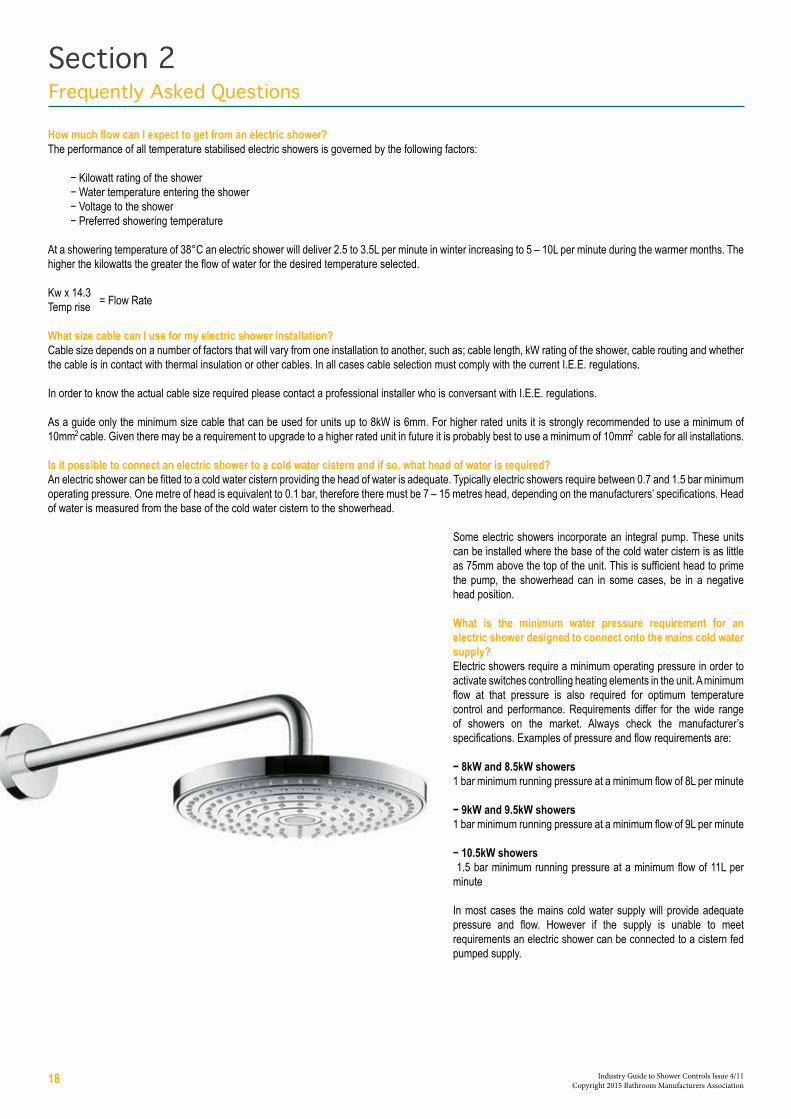
How much flow can I expect to get from an electric shower?The performance of all temperature stabilised electric showers is governed by the following factors:
− Kilowatt rating of the shower− Water temperature entering the shower− Voltage to the shower− Preferred showering temperature
At a showering temperature of 38°C an electric shower will deliver 2.5 to 3.5L per minute in winter increasing to 5 – 10L per minute during the warmer months. The higher the kilowatts the greater the flow of water for the desired temperature selected.
Kw x 14.3Temp rise
What size cable can I use for my electric shower installation?Cable size depends on a number of factors that will vary from one installation to another, such as; cable length, kW rating of the shower, cable routing and whether the cable is in contact with thermal insulation or other cables. In all cases cable selection must comply with the current I.E.E. regulations.
In order to know the actual cable size required please contact a professional installer who is conversant with I.E.E. regulations.
As a guide only the minimum size cable that can be used for units up to 8kW is 6mm. For higher rated units it is strongly recommended to use a minimum of 10mm cable. Given there may be a requirement to upgrade to a higher rated unit in future it is probably best to use a minimum of 10mm cable for all installations.
Is it possible to connect an electric shower to a cold water cistern and if so, what head of water is required?An electric shower can be fitted to a cold water cistern providing the head of water is adequate. Typically electric showers require between 0.7 and 1.5 bar minimum operating pressure. One metre of head is equivalent to 0.1 bar, therefore there must be 7 – 15 metres head, depending on the manufacturers’ specifications. Head of water is measured from the base of the cold water cistern to the showerhead.
Some electric showers incorporate an integral pump. These units can be installed where the base of the cold water cistern is as little as 75mm above the top of the unit. This is sufficient head to prime the pump, the showerhead can in some cases, be in a negative head position.
What is the minimum water pressure requirement for an electric shower designed to connect onto the mains cold water supply?Electric showers require a minimum operating pressure in order to activate switches controlling heating elements in the unit. A minimum flow at that pressure is also required for optimum temperature control and performance. Requirements differ for the wide range of showers on the market. Always check the manufacturer’s specifications. Examples of pressure and flow requirements are:
− 8kW and 8.5kW showers1 bar minimum running pressure at a minimum flow of 8L per minute
− 9kW and 9.5kW showers1 bar minimum running pressure at a minimum flow of 9L per minute
− 10.5kW showers 1.5 bar minimum running pressure at a minimum flow of 11L per minute
In most cases the mains cold water supply will provide adequate pressure and flow. However if the supply is unable to meet requirements an electric shower can be connected to a cistern fed pumped supply.
Section 2Frequently Asked Questions
= Flow Rate
22
18 Industry Guide to Shower Controls Issue 4/11 Copyright 2015 Bathroom Manufacturers Association

AirlockSection of pipework which, due to its layout, enables a pocket of air to be trapped. This results in zero or very little flow through the pipe.
Air SwitchA manual means of overriding a flow switch for initial energisation of the pump.
All-in-One Power ShowersA product which houses a pump and some form of integrated shower control. It needs a low pressure cistern fed supply of stored hot and cold water.
Anti SurgeA feature which restricts the possibility of fluctuating volumes of water movement through a system.
Automatic Air VentA mechanical device similar to a car carburettor float chamber that is used to remove quantities of air trapped in plumbing pipework.
BackflowFlow in a direction contrary to the intended normal direction of flow.
BacksiphonageBackflow caused by the siphonage of liquid from a cistern or appliance into the pipe feeding it, possibly leading to contamination of the water supply.
BarA unit of measurement of water pressure approximately equivalent to a column of water 10m high or 14.5 lbf/in (or 100 kPa) per bar.
B.E.A.BBEAB Approved Mark
Body JetsWall mounted sprays usually installed in multiples.
Body ShowersSee Body Jets.
Body SpraysSee Body Jets.
BoilerAn enclosed vessel in which water is heated by the direct or indirect application of heat.
Bonding ClampA metal strap fastened to a pipe or fitting to enable electrical bonding (earthing).
Built-inA valve installed where the body is recessed in the wall.
Bulkhead FittingSee Wall Outlet Connector.
Cabinet Power ShowersSee All-in-One Power Showers.
CavitationLocalised boiling of water below 100ºC caused by a reduction in pressure due to flow conditions.
CentrifugalA type of pump design which draws water in through the eye or centre of the impeller, forcing it
out to the external edges of the pump by centrifugal force. Water is then discharged vertically.
Ceramic Disc ValveA valve where the functional parts are highly polished ceramic components which slide across each other to control water flow (and sometimes temperature).
Check ValveA plumbing fitting designed to allow water to flow in one direction only.
CisternA fixed container for holding water at atmospheric pressure. It is normally fitted with a float operated valve and warning pipe or a no less efficient device.
Cold Water Storage CisternFixed container for holding water at atmospheric pressure usually used for providing a feed to a vented domestic hot water cylinder. It can also be used to provide a vented cold supply to terminal fittings.
Combination BoilerBoiler which heats water as used. Fed by the mains, hot and cold water is balanced when supplying fittings. Does not require a hot water cylinder or cold water tank. Also heats water for central hearing system.
ConcealedSee Built-in.
Cross flowWater flowing from one side of a hot/cold water mixer to the other, possibly leading to contamination of the water supply.
Cylinder FlangeA plumbing fitting which can be fitted to a hot water cylinder to provide a dedicated hot water supply to a terminal fitting.
Distributing PipeAny pipe (other than a flush pipe or warning pipe) conveying water from a Cold Water Storage Cistern, or from hot water apparatus supplied from a cistern and under pressure from that cistern.
DiverterA fitting used to control the direction of water to various outlets.
Double Check Valve (Verifiable)A device which is designed to prevent back siphonage, consisting of two check valves in series with a test point between the two.
Double Ended PumpSee Twin Pump.
Double Pole SwitchAn electrical switching device in which the continuity of both the mains live and neutral is broken upon the action of the switch giving a contact separation of at least 3mm. The earth always remains connected.
DownstreamWater flowing away from a given point of reference.
Section 3Industry Terminology
19 Industry Guide to Shower Controls Issue 4/11 Copyright 2015 Bathroom Manufacturers Association

Duty CycleRating as specified on a pump. The operating time of a pump expressed as a time ‘on’ and a time ‘off’. A continuously rated pump can be operated non stop.
Dynamic PressureMaintained Pressure. The water pressure in the pipework to a fitting whilst flow is taking place.
E.L.C.B.Earth Leakage Circuit Breaker. See R.C.D.
ElementA component used in an instantaneous electric shower to heat the water.
EquamaticA term used to describe a pressure balancing mixing valve.
Expansion PipeSee Vent Pipe.
Expansion VesselSee Pressure Accumulator.
Exposed Bar Shower ValveA surface mounted exposed thermostatic shower valve, when fixed sits off the wall.
Feed CisternSee Cold Water Storage Cistern.
Fixed Shower HeadAn overhead fixed height shower head.
Float Operated ValveA valve used to control the flow of water into a cistern, the valve being controlled by the level of water in the cistern.
FlowThe volume of water moving through a given point, normally expressed in litres per minute, gallons per hour or metres cubed.
Flow LimiterSee Flow Regulator.
Flow PressureSee Dynamic Pressure.
Flow RegulatorA device with moving parts which responds to variable inlet pressures to control flow at a reasonably constant rate. These are subdivided into two types:
(a) Fixed - manufactured in a range of predetermined flow rate settings.
(b) Variable - manually adjustable to provide different flow rate settings.
Flow RestrictorA device with no moving parts which restricts flow. Unlike a flow regulator it does not keep a constant flow when the supply pressure varies.Flow SwitchElectro mechanical device that senses a gravity flow of water which is typically used to start a pump.
Flush FitSee Built-in.
Free Outlet Flow RateSee Open Outlet Flow Rate.
Fused SpurA branch off an electrical ring main to a double pole switched connection box fitted with a fuse to enable the connection of a fixed electrical appliance.
General Pressure (GP)Refers to water supplied within a pressure range of between 0.1 bar to 5.0 bar.
Gravity pressureGenerally refers to water that receives its pressure as it falls from a cistern located in the roof space, or at a point higher than the terminal fitting. The pressure obtained is relevant to the height of the fall or head (1 metre head = 0.1bar), the greater the fall, higher the pressure.
Generally this refers to low pressure in most domestic dwellings, however a head above 10 meters can be classed as high.
HandsetSee Hand Shower.
Handset HolderSee Wall Bracket.
Hand ShowerA shower head attached to a flexible shower hose also termed a shower handset.
Header TankSee Cold Water Storage Cistern.
High Pressure (HP)Refers to water supplied at 1.0 bar to 5.0 bar.
Hose RestrainerA device through which a shower hose passes, sometimes used to prevent backflow.
Hose Retaining RingSee Hose Restrainer.
Hot Water CylinderA cylindrical closed vessel capable of containing water under pressure greater than atmospheric.
I.E.T.The Institution of Engineering and Technology.
ImpellerThe internal part of a pump that is driven by a motor, and is used to pressurise the water.
Indirect CylinderA hot water cylinder in which the stored water is heated by a primary heater through which hot water is circulated from a boiler. There is no mixing of the primary and secondary water.
Inlet PumpSee Twin Pump.
Instantaneous Electric ShowerA shower that electrically heats the water whilst the water is passing through it.
Instantaneous Gas Water HeaterAn appliance which heats water on demand whilst the water is passing through it.
Insulation ResistanceThe effectiveness of the electrical insulation between the current carrying conductors and the
20 Industry Guide to Shower Controls Issue 4/11 Copyright 2015 Bathroom Manufacturers Association

earth.
Integrated Power ShowersSee All-in-One Power Showers.
Low Pressure (LP)Refers to water supplied at 0.1 bar to 1.0 bar.
Maintained PressureSee Dynamic Pressure.
Manual Mixing ValveA device which does not compensate for variations in the temperature or pressure of the incoming water supplies and needs to be adjusted manually.
Miniature Circuit Breaker (M.C.B.)A Miniature Circuit Breaker is an electrical circuit protection device used as an alternative to rewireable and cartridge type fuses. It trips out when too much current flows in the circuit, typically on fault conditions. Do not confuse with R.C.D.
Mixer ShowerThe mixing valve and fittings.
Modulating Instantaneous Gas Water HeaterAn instantaneous gas water heater or boiler which is fitted with a gas control mechanism to vary the heat input and produce a relatively stable domestic hot water temperature, often termed fully modulating. Step modulating: Gas controlled heat being less able to maintain a constant output temperature under varying flow rate conditions.
Multi - PointAn instantaneous water heater which can supply water to more than one outlet, but not usually simultaneously.
Negative HeadIf the cistern is below the level of the shower head a gravity flow of water will not occur. A pump with special switching can be used to obtain a flow of water.
Non-Latching SwitchIdentical to a bathroom ceiling light pull-cord switch, except that electrical contact is only made when the cord is being pulled.
Non-Return ValveSee Check Valve.
Open Outlet Flow RateMaximum potential flow rate from a mixing valve without shower fittings attached.
Outlet PumpSee Single Pump.
Parking BracketSee Wall Bracket.
Printed Circuit Board (P.C.B.)A board commonly made of glass fibre material or plastic, onto which a circuit layout to interconnect a number of electrical components is laid.
Positive HeadA volume of water held above the highest point on the system, allowing a flow of water through the pipework and out of the discharge point by gravity.
Pressure AccumulatorA pressure vessel inside which is fitted a bladder to accommodate thermal expansion of water or alternatively to absorb the pressure shock waves of water hammer. Also known as expansion vessel.
Pressure Balancing Mixing ValveA pressure balancing compensatory shower mixing valve designed to maintain a constant shower temperature under variable inlet pressures but maintained inlet temperatures.
Pressure CompensatingSee Pressure Balancing Mixing Valve.
Pressure Regulating ValveGives constant downstream pressure, irrespective of upstream pressure with built-in non-return valves.
Pressure Relief DeviceSafety device fitted to prevent excessive pressure building up within an electric shower heater.
Pressure Relief ValveSpring loaded relief valve fitted to cold supply on unvented systems to relieve excess pressure safely to atmosphere.
Pressure SwitchA means of controlling the pump or other electrical equipment, by sensing a difference in pressure within a system.
PrimedAll air has been exhausted from a system/pump.
Proportioning ValveA manually or electronically controlled valve that regulates the flow of hot or cold water. Usually used as a pair to mix water to a required temperature.
Pump HoseA flexible pipe that connects a pump to rigid pipework.
Residual Current Device (R.C.D)A Residual Current Device is an accurate electrical balance that measures the electrical loading on the outgoing live and return neutral conductors. If any current leakage exceeds the trip value under a fault condition it turns off the power supply.
An R.C.D. is sometimes known as E.L.C.B., R.C.C.B. or trip switch. Do not confuse with M.C.B.
RecessedSee Built-in.
RelayAn electrical control device that uses a low voltage or current to operate a switch that can handle high currents and voltages.
Right Angle ConnectorSee Wall Outlet Connector.
Riser RailSee Wall Bar.
Running PressureSee Dynamic Pressure.Servicing ValveA valve for shutting off the flow of water in a pipe connected to a water fitting to facilitate the maintenance or servicing of that fitting.
Shower CabinA complete pre–assembled shower/steam room usually consisting of overhead, hand and body showers.
Shower ColumnSee Shower Panel.
Shower ControlsAny device that supplies and controls hot and cold water supplies for the purposes of showering.
Shower HeadA device designed to produce a spray pattern.
Shower HoseA flexible pipe that connects between the shower handset and the shower control.
Shower PanelA pre–assembled shower unit consisting of one or more jets, requiring minimal installation. Wall mounted, these units usually come with a variety of options ranging from thermostatic or manual mixing, with fixed overhead, flexible hand showers and body showers, which can be manually or electronically controlled.
Showering StationSee Wall Bracket.
Shower TowerSee Shower Panel.
Single Ended PumpSee Single Pump.
Single Outlet PumpSee Single Pump.
Single PumpA pump used for drawing water from a mixing valve for delivery to a shower.
Slide BarSee Wall Bar.
Solenoid ValveAn electrically operated valve giving either no flow or full flow.
Static PressureThe water pressure existing at a fitting when no flow is taking place.
Standing PressureSee Static Pressure.
Storage CisternA cistern, other than a flushing cistern, which is used to store water for subsequent use.
21 Industry Guide to Shower Controls Issue 4/11 Copyright 2015 Bathroom Manufacturers Association

StrainerA screen to prevent debris from entering a water fitting.
Supply PipeA pipe conveying mains cold water around the building.
Supply Stop ValveA valve used to isolate the mains cold water supply within a building.
Temperature Relief ValveA valve which opens automatically at a specified temperature to discharge fluid.
Thermal Storage Hot Water SystemA hot water system where cold mains pressure water is heated (instantaneously) as it passes through a heat exchanger surrounded by a stored volume of hot water.
ThermostatTemperature sensitive device producing a linear or rotary motion to control the mixing of hot and cold water within a thermostatic mixing valve.
Thermostatic Mixing ValveA device to compensate for variations in the temperature and, or pressure of the incoming water supplies, to maintain a selected blend temperature.
TransformerAn Electrical device for converting mains voltage to low voltage.
Twin Ended PumpSee Twin Pump.
Twin Impeller PumpSee Twin Pump.
Twin PumpTwo pumps driven by a single motor, boosting both hot and cold supplies to a shower mixer and/or other terminal fittings (two pumps can be used in place of a twin pump).
Unvented Domestic Hot Water SystemA plumbing system where the cold feed is taken directly from the mains to provide a high pressure hot water supply. There is no open vent to atmosphere.
UpstreamWater flowing towards a given point of reference.
Vent PipeAn uninterrupted safety pipe which allows air or expansion of water within a hot water system to escape to atmosphere.
Wall BarA vertical rail assembly to allow height adjustment of a ‘parked’ hand shower.
Wall BracketFixed device for holding hand showers.
Wall ElbowSee Wall Outlet Connector.
Wall Outlet ConnectorWall mounted device to enable a flexible shower hose to be connected to concealed pipework.
Warning PipeAn overflow pipe positioned so that its outlet is in a conspicuous position so that the discharge can be readily seen.
Water FittingsIncludes pipes, taps, ferrules, valves, cisterns, mixing valves and similar apparatus used in connection with the supply of water within a building.
Water Jacketed Tube HeaterSee Thermal Storage Hot Water System.
Wax Capsule DeviceSee Thermostat.
22 Industry Guide to Shower Controls Issue 4/11 Copyright 2015 Bathroom Manufacturers Association

Institute of Enginerring and Technology (I.E.T) Wiring RegulationsThe IET manages the national committee JPEL/64 which prepares and updates the regulations for the safety of electrical installations in buildings, and publishes the standard BS 7671:2008+A3:2015 (the IET Wiring Regulations). It also provides and publishes extensive guidance upon the standard as well as related codes of practice.http://electrical.theiet.org/wiring-regulations/index.cfm
Building RegulationsThe Building Regulations are a set of minimum requirements, applicable in England and Wales. They are designed to secure the health, safety and welfare of people in and around buildings and to conserve fuel and energy. They are made by the Secretary of State under powers given by Section 1 of the Building Act 1984.www.planningportal.gov.uk/buildingregulations/approveddocuments
Local Building ControlBuilding Control is an umbrella term covering all Local Authority Building Control Departments in England & Wales. These departments have a statutory duty to enforce Building Regulations. The Building Regulations are designed to ensure that the highest standards of construction apply to all buildings, and that the health and safety of people using and working in and around buildings is adequately provided for. http://www.labc.uk.com
Part P of the Building RegulationsPart P, brings domestic electrical installation work in England and Wales under the legal framework of the Building Regulations which places a legal requirement for safety upon electrical installation work in dwellings, although the sector is highly regarded for its high levels of conformity with its principal standard, BS 7671:2008+A3:2015.
Water Supply (Water Fittings) Regulations 1999The Water Supply (Water Fittings) Regulations 1999 (or Byelaws 2000 in Scotland) are national requirements for the design, installation and maintenance of plumbing systems, water fittings and water-using appliances. Their purpose is to prevent misuse, waste, undue consumption or erroneous measurement of water and, most importantly, to prevent contamination of drinking water. They replace the former Water Byelaws which each water supplier had administered for similar purposes for many years. www.legislation.gov.uk/uksi/1999/1148/contents/made
BEAB – Approved MarkSpecifies requirements that relate to the BEAB product certification schemes and the use of Marks licensed by BEAB.http://www.intertek.com/marks/beab
BS 3036:1958 - Semi Enclosed (rewireable) Fuse/ - BS HD 60269-2:2010 and BS 88-2:2010 HBC FusesDevices used to detect overloads, and to break the circuit for protection against them, they fall into three main categories:
1) Semi-enclosed (rewireable) fuses to BS 3036:1958 and cartridge fuses for use in plugs to BS 1362:1973.
2) Low voltage fuses. Household to BS HD 60269-3:2010+A1:2013 and BS 88-3:2010.
3) Circuit breakers, miniature and moulded case types to BS EN 60898-1:2003+A13:2012 and BS EN 60898-2:2006.
BS 8558:2011Guide to the design, installation, testing and maintenance of services supplying water for domestic use within buildings and their curtilages.
BS EN 1111:1999 (HP)Specification for High Pressure TMV Type 2 Mixing Valves.
BS EN 1287:1999 (LP)Specification for Low Pressure TMV Type 2 Mixing Valves.
BS 7942: 2011Thermostatic mixing valves for use in Care establishments. Mirrors the requirements of DO8.
Department of Health (DH) DO8A specification for thermostatic mixing valves with enhanced thermal performance. www.buildcert.com/nsf-wrc_tmv.htm
NSF WRc LimitedProvide analysis, testing and consultancy in the areas of water supply and use combining strong laboratory capabilities with expert interpretation. NSF-WRc is a joint venture of WRc plc and NSF International with laboratories in South Wales and the Thames Valley. http://www.wrcnsf.com
References to Water Regulations apply to England and Wales.
Data may vary for Scotland and Northern Ireland - please check for specific regulations applicable.
Section 4References
23 Industry Guide to Shower Controls Issue 4/11 Copyright 2015 Bathroom Manufacturers Association