Show and Tell - Lofts and Guide Curves - University of Idaho
8
Show and Tell - Lofts and Guide Curves Topics Covered: Offset Reference Planes, Convert Entities, For Construction, Loft Profiles, Guide Curves Why use a loft? Lofts allow you to create arbitrary 3D shapes defined by two or more 2-D “profiles”, and for which the path between them can be defined by one or more sketches called “guide curves”. The figure below, shows an example model (left), the use of 3 profiles and 3 guide curves to define a loft (middle), and the final lofted model (right). The loft starts from a square on the left, tapers down to a smaller circle in the middle, and then fans out into a slot on the right. Pre-loft shape Adding profiles and guide curves Final lofted model The initial “pre-loft” model (left) is composed of a revolve (middle) and an extruded square boss up to the revolved surface (right). Reference planes In this example, one plane (Plane1) already exists from making Boss-Extrude2, and two addition offset planes must be added for sketching the profiles. Reference planes can be added in several ways: a) from the feature toolbar by selecting Reference Geometry Planes, b) from the dropdown menus by selecting Insert Reference Geometry Plane, or c) holding CTRL, depressing the left mouse click over an existing plane, dragging the mouse, and releasing (this creates an offset reference plane, parallel to the plane used). Download the “pre-loft” starting model: A “pre-loft” starting model can be downloaded from in- class activities column on class day 9 or 10. The base feature (in this case) was created by a Revolve of Sketch3 about an axis (creating Revolve1), and then an Extrude of Sketch4 from reference plane Plane1 up to the outer surface of Revolve1 (creating Boss-Extrude2).
Transcript of Show and Tell - Lofts and Guide Curves - University of Idaho
Show and Tell - Lofts and Guide Curves
Topics Covered: Offset Reference Planes, Convert Entities, For Construction, Loft Profiles, Guide Curves
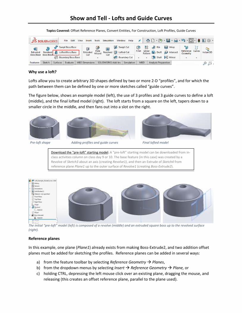
Why use a loft?
Lofts allow you to create arbitrary 3D shapes defined by two or more 2-D “profiles”, and for which the
path between them can be defined by one or more sketches called “guide curves”.
The figure below, shows an example model (left), the use of 3 profiles and 3 guide curves to define a loft
(middle), and the final lofted model (right). The loft starts from a square on the left, tapers down to a
smaller circle in the middle, and then fans out into a slot on the right.
Pre-loft shape Adding profiles and guide curves Final lofted model
The initial “pre-loft” model (left) is composed of a revolve (middle) and an extruded square boss up to the revolved surface (right).
Reference planes
In this example, one plane (Plane1) already exists from making Boss-Extrude2, and two addition offset
planes must be added for sketching the profiles. Reference planes can be added in several ways:
a) from the feature toolbar by selecting Reference Geometry Planes,
b) from the dropdown menus by selecting Insert Reference Geometry Plane, or
c) holding CTRL, depressing the left mouse click over an existing plane, dragging the mouse, and
releasing (this creates an offset reference plane, parallel to the plane used).
Download the “pre-loft” starting model: A “pre-loft” starting model can be downloaded from in-
class activities column on class day 9 or 10. The base feature (in this case) was created by a
Revolve of Sketch3 about an axis (creating Revolve1), and then an Extrude of Sketch4 from
reference plane Plane1 up to the outer surface of Revolve1 (creating Boss-Extrude2).
Show and Tell - Lofts and Guide Curves
Loft Instructions
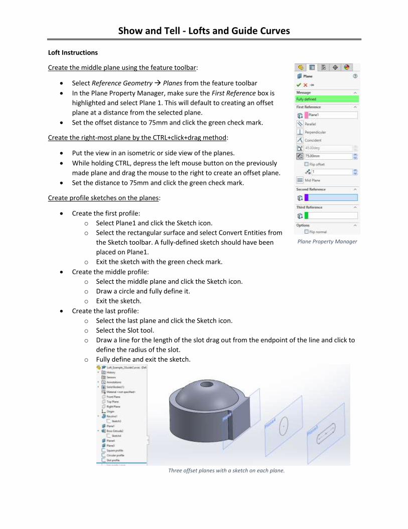
Create the middle plane using the feature toolbar:
Select Reference Geometry Planes from the feature toolbar
In the Plane Property Manager, make sure the First Reference box is
highlighted and select Plane 1. This will default to creating an offset
plane at a distance from the selected plane.
Set the offset distance to 75mm and click the green check mark.
Create the right-most plane by the CTRL+click+drag method:
Put the view in an isometric or side view of the planes.
While holding CTRL, depress the left mouse button on the previously
made plane and drag the mouse to the right to create an offset plane.
Set the distance to 75mm and click the green check mark.
Create profile sketches on the planes:
Create the first profile:
o Select Plane1 and click the Sketch icon.
o Select the rectangular surface and select Convert Entities from
the Sketch toolbar. A fully-defined sketch should have been
placed on Plane1.
o Exit the sketch with the green check mark.
Create the middle profile:
o Select the middle plane and click the Sketch icon.
o Draw a circle and fully define it.
o Exit the sketch.
Create the last profile:
o Select the last plane and click the Sketch icon.
o Select the Slot tool.
o Draw a line for the length of the slot drag out from the endpoint of the line and click to
define the radius of the slot.
o Fully define and exit the sketch.
Three offset planes with a sketch on each plane.
Plane Property Manager
Show and Tell - Lofts and Guide Curves
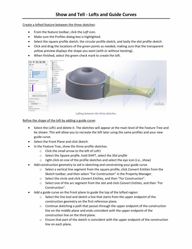
Create a lofted feature between the three sketches:
From the feature toolbar, click the Loft icon.
Make sure the Profiles dialog box is highlighted.
Select the square profile sketch, the circular profile sketch, and lastly the slot profile sketch.
Click and drag the locations of the green points as needed, making sure that the transparent
yellow preview displays the shape you want (with or without twisting).
When finished, select the green check mark to create the loft.
Lofting between the three sketches.
Refine the shape of the loft by adding a guide curve:
Select the Loft1 and delete it. The sketches will appear at the main level of the Feature Tree and
be shown. This will allow you to recreate the loft later using the same profiles and your new
guide curve.
Select the Front Plane and click Sketch.
In the Feature Tree, show the three profile sketches.
o Click the small arrow to the left of Loft1
o Select the Square profile, hold SHIFT, select the Slot profile
o right-click on one of the profile sketches and select the eye icon (i.e., show)
Add construction geometry to aid in sketching and constraining your guide curve.
o Select a vertical line segment from the square profile, click Convert Entities from the
Sketch toolbar, and then select “For Construction” in the Property Manager.
o Select the circle and click Convert Entities, and then “For Construction”.
o Select one of the arc segment from the slot and click Convert Entities, and then “For
Construction”.
Add a guide curve on the Front plane to guide the top of the lofted region:
o Select the line tool and sketch a line that starts from the upper endpoint of the
construction geometry on the first reference plane.
o Continue sketching a path that passes through the upper endpoint of the construction
line on the middle plane and ends coincident with the upper endpoint of the
construction line on the third plane.
o Ensure that part of the sketch is coincident with the upper endpoint of the construction
line on each plane.

Show and Tell - Lofts and Guide Curves
o Exit the sketch and rename it to something like “top guide curve”.
Re-create the loft including the three profile sketches in the Profiles box and the top guide curve
in the Guide Curves box.
Refine the model further by adding a second guide curve on the lower side of the profiles:
Select the Loft1 and delete it.
Select the Front Plane and click Sketch.
In the Feature Tree, show the three profile sketches.
o Click the small arrow to the left of Loft1
o Select the Square profile, hold SHIFT, select the top guide curve.
o right-click on one of the profile sketches and select the eye icon (i.e., show)
Add a guide curve on the Front plane to guide the bottom of the lofted region:
o Select the line tool and sketch a line that starts from the lower endpoint of the
construction geometry on the first reference plane.
o Continue
sketching a
path that
passes through
the lower
endpoint of the
construction
line on the
middle plane
and ends
coincident with the lower endpoint of the construction line on the third plane.
o Ensure that part of the sketch is coincident with the lower endpoint of the construction
line on each plane.
o Exit the sketch and rename it to something like “bottom guide curve”.
Re-create the loft including the three profile sketches in the Profiles box and the two guide
curves in the Guide Curves box.
Show and Tell - Lofts and Guide Curves
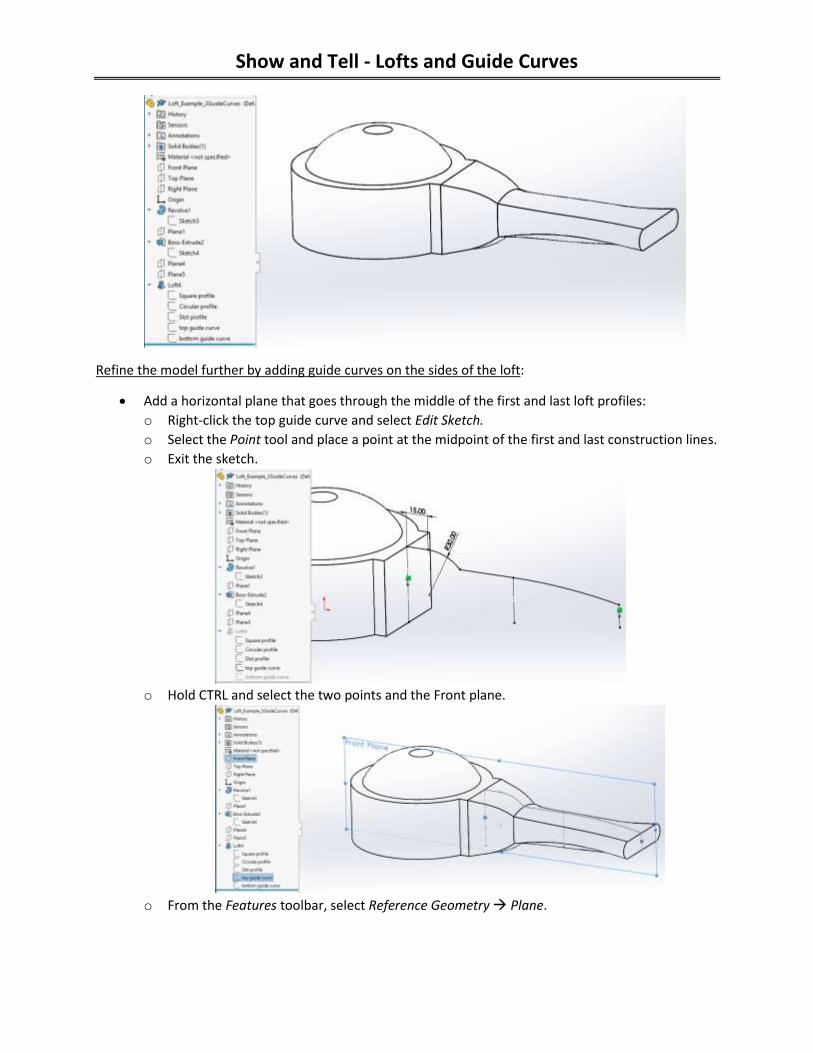
Refine the model further by adding guide curves on the sides of the loft:
Add a horizontal plane that goes through the middle of the first and last loft profiles:
o Right-click the top guide curve and select Edit Sketch.
o Select the Point tool and place a point at the midpoint of the first and last construction lines.
o Exit the sketch.
o Hold CTRL and select the two points and the Front plane.
o From the Features toolbar, select Reference Geometry Plane.
Show and Tell - Lofts and Guide Curves
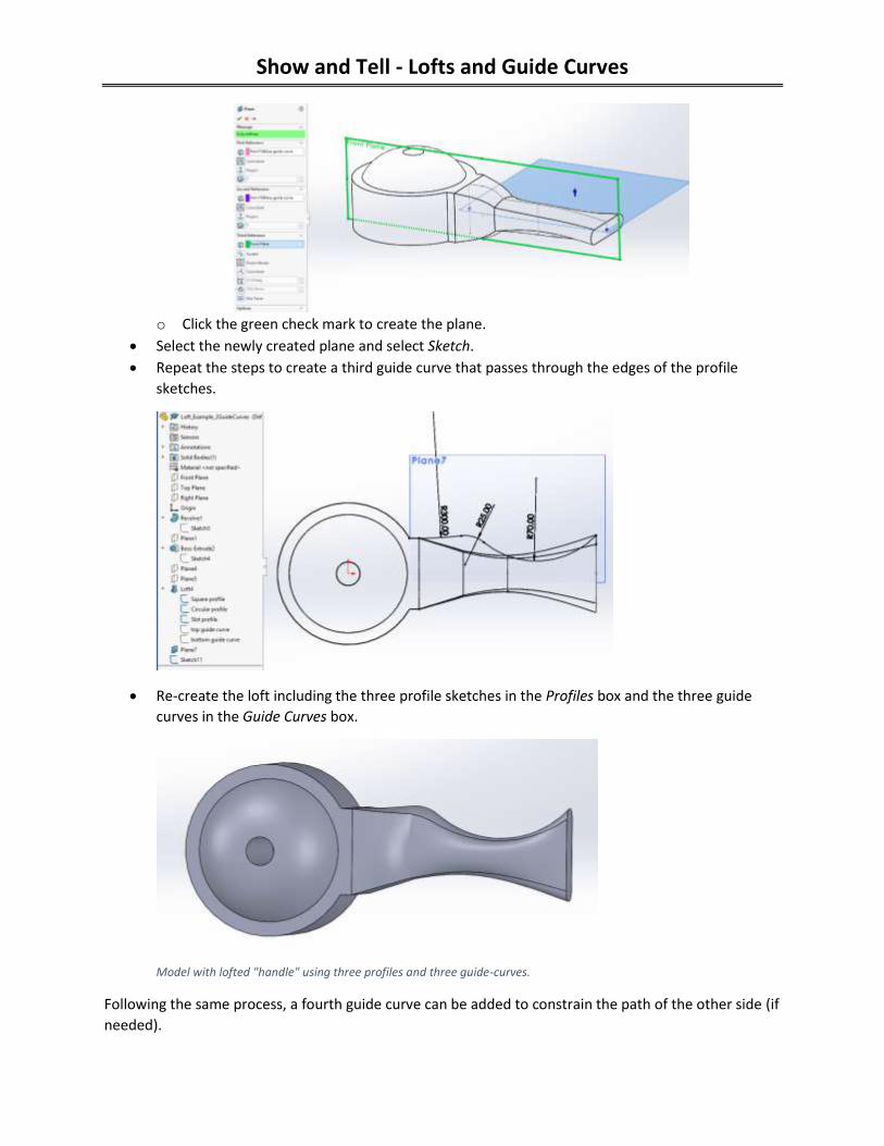
o Click the green check mark to create the plane.
Select the newly created plane and select Sketch.
Repeat the steps to create a third guide curve that passes through the edges of the profile
sketches.
Re-create the loft including the three profile sketches in the Profiles box and the three guide
curves in the Guide Curves box.
Model with lofted "handle" using three profiles and three guide-curves.
Following the same process, a fourth guide curve can be added to constrain the path of the other side (if
needed).
Show and Tell - Lofts and Guide Curves
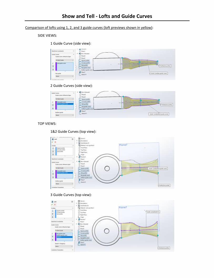
Comparison of lofts using 1, 2, and 3 guide curves (loft previews shown in yellow):
SIDE VIEWS:
1 Guide Curve (side view):
2 Guide Curves (side view):
TOP VIEWS:
1&2 Guide Curves (top view):
3 Guide Curves (top view):

Show and Tell - Lofts and Guide Curves
Lofted model using 3 guide curves:
View 1
View 2