F&IINTERVIEWPROCESS. When you shortcut the process you shortcut your profits!!

Shortcut Key Guide
2
TABLE OF CONTENTS
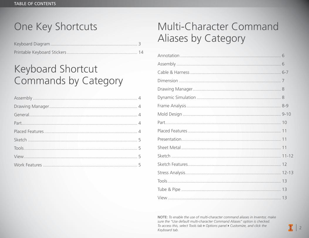
One Key Shortcuts
Keyboard Diagram ..................................................................... 3
Printable Keyboard Stickers ........................................................ 14
Keyboard Shortcut Commands by Category
Assembly ................................................................................... 4
Drawing Manager ...................................................................... 4
General ...................................................................................... 4
Part ............................................................................................ 4
Placed Features .......................................................................... 4
Sketch ....................................................................................... 5
Tools .......................................................................................... 5
View .......................................................................................... 5
Work Features ........................................................................... 5
Multi-Character Command Aliases by Category
Annotation ................................................................................ 6
Assembly ................................................................................... 6
Cable & Harness ........................................................................ 6-7
Dimension ................................................................................. 7
Drawing Manager ...................................................................... 8
Dynamic Simulation ................................................................... 8
Frame Analysis ........................................................................... 8-9
Mold Design .............................................................................. 9-10
Part ............................................................................................ 10
Placed Features .......................................................................... 11
Presentation ............................................................................... 11
Sheet Metal ............................................................................... 11
Sketch ....................................................................................... 11-12
Sketch Features .......................................................................... 12
Stress Analysis ............................................................................ 12-13
Tools .......................................................................................... 13
Tube & Pipe ............................................................................... 13
View .......................................................................................... 13
NOTE: To enable the use of multi-character command aliases in Inventor, make sure the “Use default multi-character Command Aliases” option is checked. To access this, select Tools tabOptions panelCustomize, and click the Keyboard tab.
3
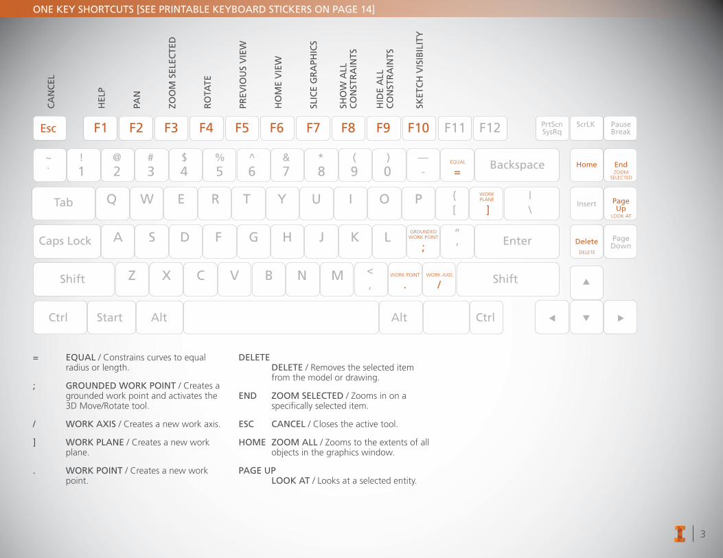
ONE KEY SHORTCUTS [SEE PRINTABLE KEYBOARD STICKERS ON PAGE 14]
F1 F2 F3 F4 F5 F6 F7 F8 F9 F10 F11 F12
ACaps Lock Enter
Backspace
PrtScnSysRq
Home End
Insert PageUp
Delete PageDown
PauseBreak
ScrLK
Shift Shift
Esc
Tab
Ctrl Start Alt Alt Ctrl
S D F G H J K L
Z X C V B N M
Q
1! @ # $ % ^ & * ( ) —
-~`
<, .
;“‘
{[ ]
|\
/
=2 3 4 5 6 7 8 9 0
W E R T Y U I O P
DELETE
WORK POINT WORK AXIS
WORKPLANE
EQUAL
GROUNDEDWORK POINT
LOOK AT
ZOOMSELECTED
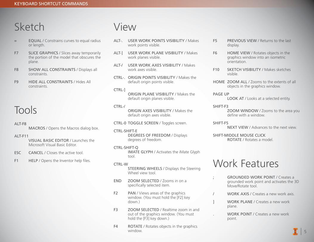
= EQUAL / Constrains curves to equal radius or length.
; GROUNDED WORK POINT / Creates a grounded work point and activates the 3D Move/Rotate tool.
/ WORK AXIS / Creates a new work axis.
] WORK PLANE / Creates a new work plane.
. WORK POINT / Creates a new work point.
DELETE DELETE / Removes the selected item from the model or drawing.
END ZOOM SELECTED / Zooms in on a specifically selected item.
ESC CANCEL / Closes the active tool.
HOME ZOOM ALL / Zooms to the extents of all objects in the graphics window.
PAGE UP LOOK AT / Looks at a selected entity.
ZOO
M S
ELEC
TED
HEL
P
CA
NC
EL
PAN
RO
TATE
PREV
IOU
S V
IEW
HO
ME
VIE
W
SLIC
E G
RA
PHIC
S
SHO
W A
LL
CO
NST
RA
INTS
HID
E A
LL
CO
NST
RA
INTS
SKET
CH
VIS
IBIL
ITY
4
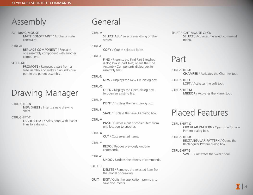
KEYBOARD SHORTCUT COMMANDS
AssemblyALT-DRAG MOUSE MATE CONSTRAINT / Applies a mate
constraint.
CTRL-H REPLACE COMPONENT / Replaces
one assembly component with another component.
SHIFT-TAB PROMOTE / Removes a part from a
subassembly and makes it an individual part in the parent assembly.
Drawing ManagerCTRL-SHIFT-N NEW SHEET / Inserts a new drawing
sheet.
CTRL-SHIFT-T LEADER TEXT / Adds notes with leader
lines to a drawing.
GeneralCTRL-A SELECT ALL / Selects everything on the
screen.
CTRL-C COPY / Copies selected items.
CTRL-F FIND / Presents the Find Part Sketches dialog box in part files; opens the Find Assembly Components dialog box in assembly files.
CTRL-N NEW / Displays the New File dialog box.
CTRL-O OPEN / Displays the Open dialog box,
to open an existing file.
CTRL-P PRINT / Displays the Print dialog box.
CTRL-S SAVE / Displays the Save As dialog box.
CTRL-V PASTE / Pastes a cut or copied item from
one location to another.
CTRL-X CUT / Cuts selected items.
CTRL-Y REDO / Redoes previously undone commands.
CTRL-Z UNDO / Undoes the effects of commands.
DELETE DELETE / Removes the selected item from the model or drawing.
QUIT EXIT / Quits the application; prompts to save documents.
SHIFT-RIGHT MOUSE CLICK SELECT / Activates the select command
menu.
PartCTRL-SHIFT-K CHAMFER / Activates the Chamfer tool.
CTRL-SHIFT-L LOFT / Activates the Loft tool.
CTRL-SHIFT-M MIRROR / Activates the Mirror tool.
Placed FeaturesCTRL-SHIFT-O CIRCULAR PATTERN / Opens the Circular
Pattern dialog box.
CTRL-SHIFT-R RECTANGULAR PATTERN / Opens the
Rectangular Pattern dialog box.
CTRL-SHIFT-S SWEEP / Activates the Sweep tool.
5
KEYBOARD SHORTCUT COMMANDS
Sketch= EQUAL / Constrains curves to equal radius
or length.
F7 SLICE GRAPHICS / Slices away temporarily the portion of the model that obscures the plane.
F8 SHOW ALL CONSTRAINTS / Displays all constraints.
F9 HIDE ALL CONSTRAINTS / Hides All constraints.
ToolsALT-F8 MACROS / Opens the Macros dialog box.
ALT-F11 VISUAL BASIC EDITOR / Launches the
Microsoft Visual Basic Editor.
ESC CANCEL / Closes the active tool.
F1 HELP / Opens the Inventor help files.
ViewALT-. USER WORK POINTS VISIBILITY / Makes
work points visible.
ALT-] USER WORK PLANE VISIBILITY / Makes work planes visible.
ALT-/ USER WORK AXES VISIBILITY / Makes work axes visible.
CTRL-. ORIGIN POINTS VISIBILITY / Makes the default origin points visible.
CTRL-] ORIGIN PLANE VISIBILITY / Makes the
default origin planes visible.
CTRL-/ ORIGIN AXES VISIBILITY / Makes the
default origin axes visible.
CTRL-0 TOGGLE SCREEN / Toggles screen.
CTRL-SHIFT-E DEGREES OF FREEDOM / Displays
degrees of freedom.
CTRL-SHIFT-Q IMATE GLYPH / Activates the iMate Glyph
tool.
CTRL-W STEERING WHEELS / Displays the Steering
Wheel view tool.
END ZOOM SELECTED / Zooms in on a specifically selected item.
F2 PAN / Views areas of the graphics window. (You must hold the [F2] key down.)
F3 ZOOM SELECTED / Realtime zoom in and out of the graphics window. (You must hold the [F3] key down.)
F4 ROTATE / Rotates objects in the graphics window.
F5 PREVIOUS VIEW / Returns to the last display.
F6 HOME VIEW / Rotates objects in the graphics window into an isometric orientation.
F10 SKETCH VISIBILITY / Makes sketches visible.
HOME ZOOM ALL / Zooms to the extents of all objects in the graphics window.
PAGE UP LOOK AT / Looks at a selected entity.
SHIFT-F3 ZOOM WINDOW / Zooms to the area you
define with a window.
SHIFT-F5 NEXT VIEW / Advances to the next view.
SHIFT-MIDDLE MOUSE CLICK ROTATE / Rotates a model.
Work Features; GROUNDED WORK POINT / Creates a
grounded work point and activates the 3D Move/Rotate tool.
/ WORK AXIS / Creates a new work axis.
] WORK PLANE / Creates a new work plane.
. WORK POINT / Creates a new work point.
6
MULTI-CHARACTER COMMAND ALIASES
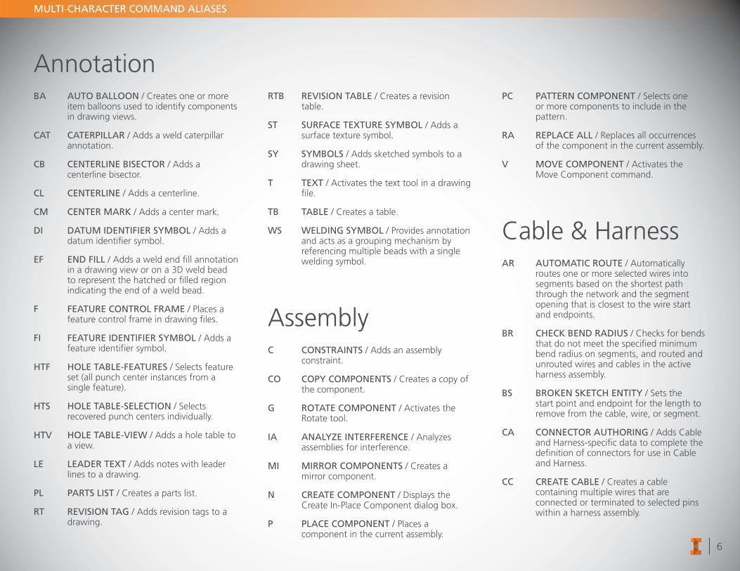
AnnotationBA AUTO BALLOON / Creates one or more
item balloons used to identify components in drawing views.
CAT CATERPILLAR / Adds a weld caterpillar annotation.
CB CENTERLINE BISECTOR / Adds a centerline bisector.
CL CENTERLINE / Adds a centerline.
CM CENTER MARK / Adds a center mark.
DI DATUM IDENTIFIER SYMBOL / Adds a datum identifier symbol.
EF END FILL / Adds a weld end fill annotation in a drawing view or on a 3D weld bead to represent the hatched or filled region indicating the end of a weld bead.
F FEATURE CONTROL FRAME / Places a feature control frame in drawing files.
FI FEATURE IDENTIFIER SYMBOL / Adds a feature identifier symbol.
HTF HOLE TABLE-FEATURES / Selects feature set (all punch center instances from a single feature).
HTS HOLE TABLE-SELECTION / Selects recovered punch centers individually.
HTV HOLE TABLE-VIEW / Adds a hole table to a view.
LE LEADER TEXT / Adds notes with leader lines to a drawing.
PL PARTS LIST / Creates a parts list.
RT REVISION TAG / Adds revision tags to a drawing.
RTB REVISION TABLE / Creates a revision table.
ST SURFACE TEXTURE SYMBOL / Adds a surface texture symbol.
SY SYMBOLS / Adds sketched symbols to a drawing sheet.
T TEXT / Activates the text tool in a drawing file.
TB TABLE / Creates a table.
WS WELDING SYMBOL / Provides annotation and acts as a grouping mechanism by referencing multiple beads with a single welding symbol.
AssemblyC CONSTRAINTS / Adds an assembly
constraint.
CO COPY COMPONENTS / Creates a copy of the component.
G ROTATE COMPONENT / Activates the Rotate tool.
IA ANALYZE INTERFERENCE / Analyzes assemblies for interference.
MI MIRROR COMPONENTS / Creates a mirror component.
N CREATE COMPONENT / Displays the Create In-Place Component dialog box.
P PLACE COMPONENT / Places a component in the current assembly.
PC PATTERN COMPONENT / Selects one or more components to include in the pattern.
RA REPLACE ALL / Replaces all occurrences of the component in the current assembly.
V MOVE COMPONENT / Activates the Move Component command.
Cable & HarnessAR AUTOMATIC ROUTE / Automatically
routes one or more selected wires into segments based on the shortest path through the network and the segment opening that is closest to the wire start and endpoints.
BR CHECK BEND RADIUS / Checks for bends that do not meet the specified minimum bend radius on segments, and routed and unrouted wires and cables in the active harness assembly.
BS BROKEN SKETCH ENTITY / Sets the start point and endpoint for the length to remove from the cable, wire, or segment.
CA CONNECTOR AUTHORING / Adds Cable and Harness-specific data to complete the definition of connectors for use in Cable and Harness.
CC CREATE CABLE / Creates a cable containing multiple wires that are connected or terminated to selected pins within a harness assembly.
7
MULTI-CHARACTER COMMAND ALIASES
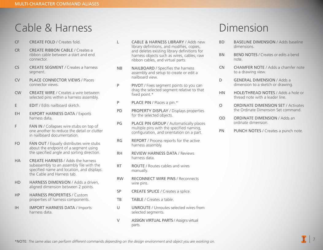
Cable & HarnessCF CREATE FOLD / Creates fold.
CR CREATE RIBBON CABLE / Creates a ribbon cable between a start and end connector.
CS CREATE SEGMENT / Creates a harness segment.
CV PLACE CONNECTOR VIEWS / Places connector views.
CW CREATE WIRE / Creates a wire between selected pins within a harness assembly.
E EDIT / Edits nailboard sketch.
EH EXPORT HARNESS DATA / Exports harness data .
F FAN IN / Collapses wire stubs on top of one another to reduce the detail or clutter in nailboard documentation.
FO FAN OUT / Equally distributes wire stubs about the endpoint of a segment using the specified angle and sorting direction.
HA CREATE HARNESS / Adds the harness subassembly to an assembly file with the specified name and location, and displays the Cable and Harness tab.
HD HARNESS DIMENSION / Adds a driven, aligned dimension between 2 points.
HP HARNESS PROPERTIES / Custom properties of harness components.
IH IMPORT HARNESS DATA / Imports harness data.
L CABLE & HARNESS LIBRARY / Adds new library definitions, and modifies, copies, and deletes existing library definitions for harness objects such as wires, cables, raw ribbon cables, and virtual parts.
NB NAILBOARD / Specifies the harness assembly and setup to create or edit a nailboard view.
P PIVOT / Fixes segment points so you can drag the selected segment relative to that fixed point.*
P PLACE PIN / Places a pin.*
PD PROPERTY DISPLAY / Displays properties for the selected objects.
PG PLACE PIN GROUP / Automatically places multiple pins with the specified naming, configuration, and orientation on a part.
RG REPORT / Process reports for the active harness assembly.
RH REVIEW HARNESS DATA / Reviews harness data.
RT ROUTE / Routes cables and wires manually.
RW RECONNECT WIRE PINS / Reconnects wire pins.
SP CREATE SPLICE / Creates a splice.
TB TABLE / Creates a table.
U UNROUTE / Unroutes selected wires from selected segments.
V ASSIGN VIRTUAL PARTS / Assigns virtual parts.
DimensionBD BASELINE DIMENSION / Adds baseline
dimensions.
BN BEND NOTES / Creates or edits a bend note.
CN CHAMFER NOTE / Adds a chamfer note to a drawing view.
D GENERAL DIMENSION / Adds a dimension to a sketch or drawing.
HN HOLE/THREAD NOTES / Adds a hole or thread note with a leader line.
O ORDINATE DIMENSION SET / Activates the Ordinate Dimension Set command.
OD ORDINATE DIMENSION / Adds an ordinate dimension.
PN PUNCH NOTES / Creates a punch note.
*NOTE: The same alias can perform different commands depending on the design environment and object you are working on.
8
MULTI-CHARACTER COMMAND ALIASES
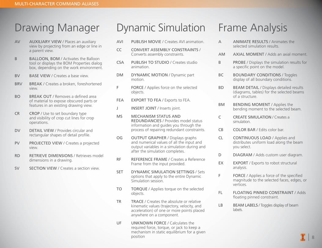
Drawing ManagerAV AUXILIARY VIEW / Places an auxiliary
view by projecting from an edge or line in a parent view.
B BALLOON, BOM / Activates the Balloon tool or displays the BOM Properties dialog box, depending on the work environment.
BV BASE VIEW / Creates a base view.
BRV BREAK / Creates a broken, foreshortened view.
BO BREAK OUT / Removes a defined area of material to expose obscured parts or features in an existing drawing view.
CR CROP / Use to set boundary type and visibility of crop cut lines for crop operations.
DV DETAIL VIEW / Provides circular and rectangular shapes of detail profile.
PV PROJECTED VIEW / Creates a projected view.
RD RETRIEVE DIMENSIONS / Retrieves model dimensions in a drawing.
SV SECTION VIEW / Creates a section view.
Dynamic SimulationAVI PUBLISH MOVIE / Creates AVI animation.
CC CONVERT ASSEMBLY CONSTRAINTS / Converts assembly constraints.
CSA PUBLISH TO STUDIO / Creates studio animation.
DM DYNAMIC MOTION / Dynamic part motion.
F FORCE / Applies force on the selected objects.
FEA EXPORT TO FEA / Exports to FEA.
J INSERT JOINT / Inserts joint.
MS MECHANISM STATUS AND REDUNDANCIES / Provides model status information and guides you through the process of repairing redundant constraints.
OG OUTPUT GRAPHER / Displays graphs and numerical values of all the input and output variables in a simulation during and after the simulation completes.
RF REFERENCE FRAME / Creates a Reference Frame from the input provided.
SET DYNAMIC SIMULATION SETTINGS / Sets options that apply to the entire Dynamic Simulation session.
TO TORQUE / Applies torque on the selected objects.
TR TRACE / Creates the absolute or relative kinematic values (trajectory, velocity, and acceleration) of one or more points placed anywhere on a component.
UF UNKNOWN FORCE / Calculates the required force, torque, or jack to keep a mechanism in static equilibrium for a given position
Frame AnalysisA ANIMATE RESULTS / Animates the
selected simulation results.
AM AXIAL MOMENT / Adds an axial moment.
B PROBE / Displays the simulation results for a specific point on the model.
BC BOUNDARY CONDITIONS / Toggles display of all boundary conditions.
BD BEAM DETAIL / Displays detailed results (diagrams, tables) for the selected beams of a structure.
BM BENDING MOMENT / Applies the bending moment to the selected beam.
C CREATE SIMULATION / Creates a simulation.
CB COLOR BAR / Edits color bar.
CL CONTINUOUS LOAD / Applies and distributes uniform load along the beam you select.
D DIAGRAM / Adds custom user diagram.
EX EXPORT / Exports to robot structural analysis.
F FORCE / Applies a force of the specified magnitude to the selected faces, edges, or vertices.
FL FLOATING PINNED CONSTRAINT / Adds floating pinned constraint.
LB BEAM LABELS / Toggles display of beam labels.
9
MULTI-CHARACTER COMMAND ALIASES
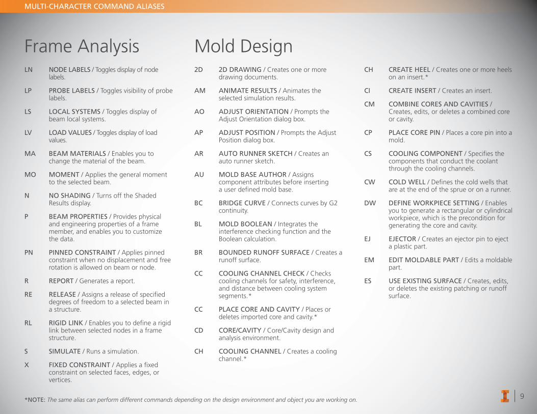
Frame AnalysisLN NODE LABELS / Toggles display of node
labels.
LP PROBE LABELS / Toggles visibility of probe labels.
LS LOCAL SYSTEMS / Toggles display of beam local systems.
LV LOAD VALUES / Toggles display of load values.
MA BEAM MATERIALS / Enables you to change the material of the beam.
MO MOMENT / Applies the general moment to the selected beam.
N NO SHADING / Turns off the Shaded Results display.
P BEAM PROPERTIES / Provides physical and engineering properties of a frame member, and enables you to customize the data.
PN PINNED CONSTRAINT / Applies pinned constraint when no displacement and free rotation is allowed on beam or node.
R REPORT / Generates a report.
RE RELEASE / Assigns a release of specified degrees of freedom to a selected beam in a structure.
RL RIGID LINK / Enables you to define a rigid link between selected nodes in a frame structure.
S SIMULATE / Runs a simulation.
X FIXED CONSTRAINT / Applies a fixed constraint on selected faces, edges, or vertices.
Mold Design2D 2D DRAWING / Creates one or more
drawing documents.
AM ANIMATE RESULTS / Animates the selected simulation results.
AO ADJUST ORIENTATION / Prompts the Adjust Orientation dialog box.
AP ADJUST POSITION / Prompts the Adjust Position dialog box.
AR AUTO RUNNER SKETCH / Creates an auto runner sketch.
AU MOLD BASE AUTHOR / Assigns component attributes before inserting a user defined mold base.
BC BRIDGE CURVE / Connects curves by G2 continuity.
BL MOLD BOOLEAN / Integrates the interference checking function and the Boolean calculation.
BR BOUNDED RUNOFF SURFACE / Creates a runoff surface.
CC COOLING CHANNEL CHECK / Checks cooling channels for safety, interference, and distance between cooling system segments.*
CC PLACE CORE AND CAVITY / Places or deletes imported core and cavity.*
CD CORE/CAVITY / Core/Cavity design and analysis environment.
CH COOLING CHANNEL / Creates a cooling channel.*
CH CREATE HEEL / Creates one or more heels on an insert.*
CI CREATE INSERT / Creates an insert.
CM COMBINE CORES AND CAVITIES / Creates, edits, or deletes a combined core or cavity.
CP PLACE CORE PIN / Places a core pin into a mold.
CS COOLING COMPONENT / Specifies the components that conduct the coolant through the cooling channels.
CW COLD WELL / Defines the cold wells that are at the end of the sprue or on a runner.
DW DEFINE WORKPIECE SETTING / Enables you to generate a rectangular or cylindrical workpiece, which is the precondition for generating the core and cavity.
EJ EJECTOR / Creates an ejector pin to eject a plastic part.
EM EDIT MOLDABLE PART / Edits a moldable part.
ES USE EXISTING SURFACE / Creates, edits, or deletes the existing patching or runoff surface.
*NOTE: The same alias can perform different commands depending on the design environment and object you are working on.
10
MULTI-CHARACTER COMMAND ALIASES
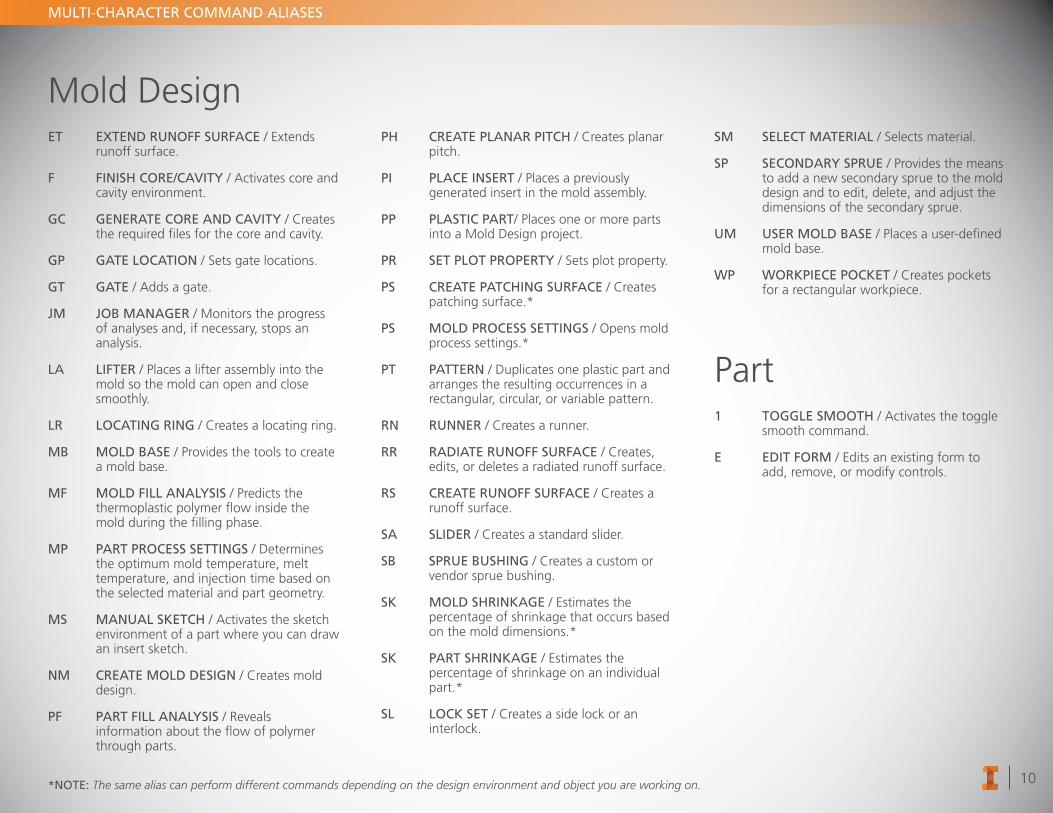
Mold DesignET EXTEND RUNOFF SURFACE / Extends
runoff surface.
F FINISH CORE/CAVITY / Activates core and cavity environment.
GC GENERATE CORE AND CAVITY / Creates the required files for the core and cavity.
GP GATE LOCATION / Sets gate locations.
GT GATE / Adds a gate.
JM JOB MANAGER / Monitors the progress of analyses and, if necessary, stops an analysis.
LA LIFTER / Places a lifter assembly into the mold so the mold can open and close smoothly.
LR LOCATING RING / Creates a locating ring.
MB MOLD BASE / Provides the tools to create a mold base.
MF MOLD FILL ANALYSIS / Predicts the thermoplastic polymer flow inside the mold during the filling phase.
MP PART PROCESS SETTINGS / Determines the optimum mold temperature, melt temperature, and injection time based on the selected material and part geometry.
MS MANUAL SKETCH / Activates the sketch environment of a part where you can draw an insert sketch.
NM CREATE MOLD DESIGN / Creates mold design.
PF PART FILL ANALYSIS / Reveals information about the flow of polymer through parts.
PH CREATE PLANAR PITCH / Creates planar pitch.
PI PLACE INSERT / Places a previously generated insert in the mold assembly.
PP PLASTIC PART/ Places one or more parts into a Mold Design project.
PR SET PLOT PROPERTY / Sets plot property.
PS CREATE PATCHING SURFACE / Creates patching surface.*
PS MOLD PROCESS SETTINGS / Opens mold process settings.*
PT PATTERN / Duplicates one plastic part and arranges the resulting occurrences in a rectangular, circular, or variable pattern.
RN RUNNER / Creates a runner.
RR RADIATE RUNOFF SURFACE / Creates, edits, or deletes a radiated runoff surface.
RS CREATE RUNOFF SURFACE / Creates a runoff surface.
SA SLIDER / Creates a standard slider.
SB SPRUE BUSHING / Creates a custom or vendor sprue bushing.
SK MOLD SHRINKAGE / Estimates the percentage of shrinkage that occurs based on the mold dimensions.*
SK PART SHRINKAGE / Estimates the percentage of shrinkage on an individual part.*
SL LOCK SET / Creates a side lock or an interlock.
SM SELECT MATERIAL / Selects material.
SP SECONDARY SPRUE / Provides the means to add a new secondary sprue to the mold design and to edit, delete, and adjust the dimensions of the secondary sprue.
UM USER MOLD BASE / Places a user-defined mold base.
WP WORKPIECE POCKET / Creates pockets for a rectangular workpiece.
Part1 TOGGLE SMOOTH / Activates the toggle
smooth command.
E EDIT FORM / Edits an existing form to add, remove, or modify controls.
*NOTE: The same alias can perform different commands depending on the design environment and object you are working on.
11
MULTI-CHARACTER COMMAND ALIASES
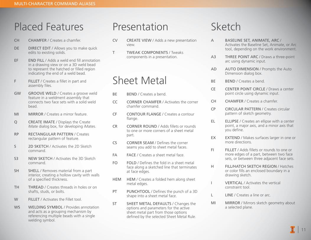
Placed FeaturesCH CHAMFER / Creates a chamfer.
DE DIRECT EDIT / Allows you to make quick edits to existing solids.
EF END FILL / Adds a weld end fill annotation in a drawing view or on a 3D weld bead to represent the hatched or filled region indicating the end of a weld bead.
F FILLET / Creates a fillet in part and assembly files.
GW GROOVE WELD / Creates a groove weld feature in a weldment assembly that connects two face sets with a solid weld bead.
MI MIRROR / Creates a mirror feature.
Q CREATE IMATE / Displays the Create iMate dialog box, for developing iMates.
RP RECTANGULAR PATTERN / Creates rectangular pattern of feature.
S 2D SKETCH / Activates the 2D Sketch command.
S3 NEW SKETCH / Activates the 3D Sketch command.
SH SHELL / Removes material from a part interior, creating a hollow cavity with walls of a specified thickness.
TH THREAD / Creates threads in holes or on shafts, studs, or bolts.
W FILLET / Activates the Fillet tool.
WS WELDING SYMBOL / Provides annotation and acts as a grouping mechanism by referencing multiple beads with a single welding symbol.
PresentationCV CREATE VIEW / Adds a new presentation
view.
T TWEAK COMPONENTS / Tweaks components in a presentation.
Sheet MetalBE BEND / Creates a bend.
CC CORNER CHAMFER / Activates the corner chamfer command.
CF CONTOUR FLANGE / Creates a contour flange.
CR CORNER ROUND / Adds fillets or rounds to one or more corners of a sheet metal part.
CS CORNER SEAM / Defines the corner seams you add to sheet metal faces.
FA FACE / Creates a sheet metal face.
FO FOLD / Defines the fold in a sheet metal face along a sketched line that terminates at face edges.
HEM HEM / Creates a folded hem along sheet metal edges.
PT PUNCHTOOL / Defines the punch of a 3D shape into a sheet metal face.
ST SHEET METAL DEFAULTS / Changes the options and parameters for the active sheet metal part from those options defined by the selected Sheet Metal Rule.
SketchA BASELINE SET, ANIMATE, ARC /
Activates the Baseline Set, Animate, or Arc tool, depending on the work environment.
A3 THREE POINT ARC / Draws a three-point arc using dynamic input.
AD AUTO DIMENSION / Prompts the Auto Dimension dialog box.
BE BEND / Creates a bend.
CE CENTER POINT CIRCLE / Draws a center point circle using dynamic input.
CH CHAMFER / Creates a chamfer.
CP CIRCULAR PATTERN / Creates circular pattern of sketch geometry.
EL ELLIPSE / Creates an ellipse with a center point, a major axis, and a minor axis that you define.
EX EXTEND / Makes surfaces larger in one or more directions.
FI FILLET / Adds fillets or rounds to one or more edges of a part, between two face sets, or between three adjacent face sets.
H FILL/HATCH SKETCH REGION / Hatches or color fills an enclosed boundary in a drawing sketch.
I VERTICAL / Activates the vertical constraint tool.
L LINE / Creates a line or arc.
MI MIRROR / Mirrors sketch geometry about a selected plane.
12
MULTI-CHARACTER COMMAND ALIASES
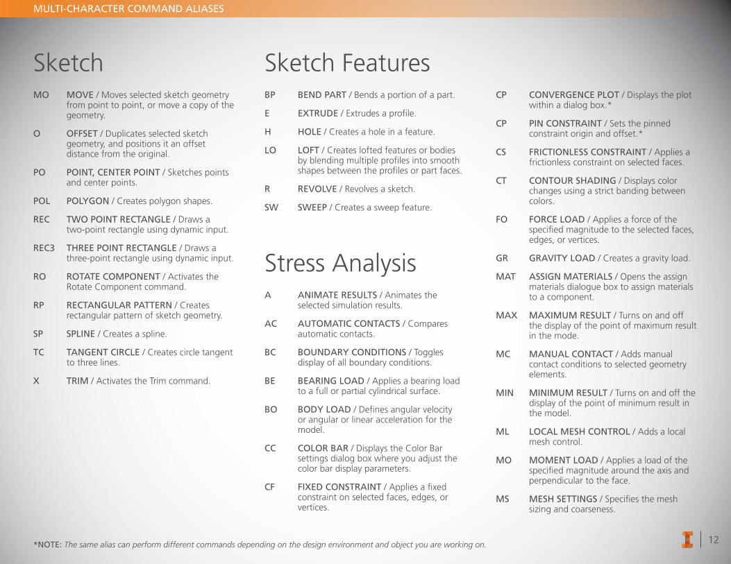
SketchMO MOVE / Moves selected sketch geometry
from point to point, or move a copy of the geometry.
O OFFSET / Duplicates selected sketch geometry, and positions it an offset distance from the original.
PO POINT, CENTER POINT / Sketches points and center points.
POL POLYGON / Creates polygon shapes.
REC TWO POINT RECTANGLE / Draws a two-point rectangle using dynamic input.
REC3 THREE POINT RECTANGLE / Draws a three-point rectangle using dynamic input.
RO ROTATE COMPONENT / Activates the Rotate Component command.
RP RECTANGULAR PATTERN / Creates rectangular pattern of sketch geometry.
SP SPLINE / Creates a spline.
TC TANGENT CIRCLE / Creates circle tangent to three lines.
X TRIM / Activates the Trim command.
Sketch FeaturesBP BEND PART / Bends a portion of a part.
E EXTRUDE / Extrudes a profile.
H HOLE / Creates a hole in a feature.
LO LOFT / Creates lofted features or bodies by blending multiple profiles into smooth shapes between the profiles or part faces.
R REVOLVE / Revolves a sketch.
SW SWEEP / Creates a sweep feature.
Stress AnalysisA ANIMATE RESULTS / Animates the
selected simulation results.
AC AUTOMATIC CONTACTS / Compares automatic contacts.
BC BOUNDARY CONDITIONS / Toggles display of all boundary conditions.
BE BEARING LOAD / Applies a bearing load to a full or partial cylindrical surface.
BO BODY LOAD / Defines angular velocity or angular or linear acceleration for the model.
CC COLOR BAR / Displays the Color Bar settings dialog box where you adjust the color bar display parameters.
CF FIXED CONSTRAINT / Applies a fixed constraint on selected faces, edges, or vertices.
CP CONVERGENCE PLOT / Displays the plot within a dialog box.*
CP PIN CONSTRAINT / Sets the pinned constraint origin and offset.*
CS FRICTIONLESS CONSTRAINT / Applies a frictionless constraint on selected faces.
CT CONTOUR SHADING / Displays color changes using a strict banding between colors.
FO FORCE LOAD / Applies a force of the specified magnitude to the selected faces, edges, or vertices.
GR GRAVITY LOAD / Creates a gravity load.
MAT ASSIGN MATERIALS / Opens the assign materials dialogue box to assign materials to a component.
MAX MAXIMUM RESULT / Turns on and off the display of the point of maximum result in the mode.
MC MANUAL CONTACT / Adds manual contact conditions to selected geometry elements.
MIN MINIMUM RESULT / Turns on and off the display of the point of minimum result in the model.
ML LOCAL MESH CONTROL / Adds a local mesh control.
MO MOMENT LOAD / Applies a load of the specified magnitude around the axis and perpendicular to the face.
MS MESH SETTINGS / Specifies the mesh sizing and coarseness.
*NOTE: The same alias can perform different commands depending on the design environment and object you are working on.
13
MULTI-CHARACTER COMMAND ALIASES
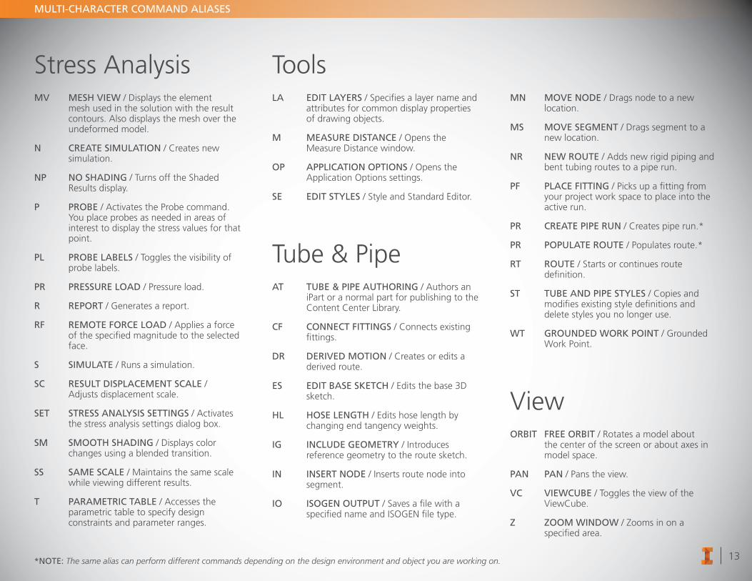
Stress AnalysisMV MESH VIEW / Displays the element
mesh used in the solution with the result contours. Also displays the mesh over the undeformed model.
N CREATE SIMULATION / Creates new simulation.
NP NO SHADING / Turns off the Shaded Results display.
P PROBE / Activates the Probe command. You place probes as needed in areas of interest to display the stress values for that point.
PL PROBE LABELS / Toggles the visibility of probe labels.
PR PRESSURE LOAD / Pressure load.
R REPORT / Generates a report.
RF REMOTE FORCE LOAD / Applies a force of the specified magnitude to the selected face.
S SIMULATE / Runs a simulation.
SC RESULT DISPLACEMENT SCALE / Adjusts displacement scale.
SET STRESS ANALYSIS SETTINGS / Activates the stress analysis settings dialog box.
SM SMOOTH SHADING / Displays color changes using a blended transition.
SS SAME SCALE / Maintains the same scale while viewing different results.
T PARAMETRIC TABLE / Accesses the parametric table to specify design constraints and parameter ranges.
ToolsLA EDIT LAYERS / Specifies a layer name and
attributes for common display properties of drawing objects.
M MEASURE DISTANCE / Opens the Measure Distance window.
OP APPLICATION OPTIONS / Opens the Application Options settings.
SE EDIT STYLES / Style and Standard Editor.
Tube & PipeAT TUBE & PIPE AUTHORING / Authors an
iPart or a normal part for publishing to the Content Center Library.
CF CONNECT FITTINGS / Connects existing fittings.
DR DERIVED MOTION / Creates or edits a derived route.
ES EDIT BASE SKETCH / Edits the base 3D sketch.
HL HOSE LENGTH / Edits hose length by changing end tangency weights.
IG INCLUDE GEOMETRY / Introduces reference geometry to the route sketch.
IN INSERT NODE / Inserts route node into segment.
IO ISOGEN OUTPUT / Saves a file with a specified name and ISOGEN file type.
MN MOVE NODE / Drags node to a new location.
MS MOVE SEGMENT / Drags segment to a new location.
NR NEW ROUTE / Adds new rigid piping and bent tubing routes to a pipe run.
PF PLACE FITTING / Picks up a fitting from your project work space to place into the active run.
PR CREATE PIPE RUN / Creates pipe run.*
PR POPULATE ROUTE / Populates route.*
RT ROUTE / Starts or continues route definition.
ST TUBE AND PIPE STYLES / Copies and modifies existing style definitions and delete styles you no longer use.
WT GROUNDED WORK POINT / Grounded Work Point.
ViewORBIT FREE ORBIT / Rotates a model about
the center of the screen or about axes in model space.
PAN PAN / Pans the view.
VC VIEWCUBE / Toggles the view of the ViewCube.
Z ZOOM WINDOW / Zooms in on a specified area.
*NOTE: The same alias can perform different commands depending on the design environment and object you are working on.
HOMEZOOM
ALL
PG UPLOOK
AT
=EQUAL
;GRNDEDWRK PT
/WRKAXIS
]WRK
PLANE
DEL ENDZOOMSELTED
ESCCANCELDELETE
.WRK PT
HOMEZOOM
ALL
PG UPLOOK
AT
=EQUAL
;GRNDEDWRK PT
/WRKAXIS
]WRK
PLANE
DEL ENDZOOMSELTED
ESCCANCELDELETE
.WRK PT
HOMEZOOM
ALL
PG UPLOOK
AT
=EQUAL
;GRNDEDWRK PT
/WRKAXIS
]WRK
PLANE
DEL ENDZOOMSELTED
ESCCANCELDELETE
.WRK PT
HOMEZOOM
ALL
PG UPLOOK
AT
=EQUAL
;GRNDEDWRK PT
/WRKAXIS
]WRK
PLANE
DEL ENDZOOMSELTED
ESCCANCELDELETE
.WRK PT
HO
ME
ZOO
MA
LL
PG U
PLO
OK
AT
=EQU
AL
;G
RN
DED
WRK
PT
/WRK
AX
IS
]WRK
PLAN
E
DEL
END
ZOO
MSELTED
ESCC
AN
CEL
DELETE
.WRK
PT
HO
ME
ZOO
MA
LL
PG U
PLO
OK
AT
=EQU
AL
;G
RN
DED
WRK
PT
/WRK
AX
IS
]WRK
PLAN
E
DEL
END
ZOO
MSELTED
ESCC
AN
CEL
DELETE
.WRK
PT
HO
ME
ZOO
MA
LL
PG U
PLO
OK
AT
=EQU
AL
;G
RN
DED
WRK
PT
/WRK
AX
IS
]WRK
PLAN
E
DEL
END
ZOO
MSELTED
ESCC
AN
CEL
DELETE
.WRK
PT
HO
ME
ZOO
MA
LL
PG U
PLO
OK
AT
=EQU
AL
;G
RN
DED
WRK
PT
/WRK
AX
IS
]WRK
PLAN
E
DEL
END
ZOO
MSELTED
ESCC
AN
CEL
DELETE
.WRK
PT
HOMEZOOM
ALL
PG UPLOOK
AT
=EQUAL
;GRNDEDWRK PT
/WRKAXIS
]WRK
PLANE
DEL ENDZOOMSELTED
ESCCANCELDELETE
.WRK PT
HOMEZOOM
ALL
PG UPLOOK
AT
=EQUAL
;GRNDEDWRK PT
/WRKAXIS
]WRK
PLANE
DEL ENDZOOMSELTED
ESCCANCELDELETE
.WRK PT
HOMEZOOM
ALL
PG UPLOOK
AT
=EQUAL
;GRNDEDWRK PT
/WRKAXIS
]WRK
PLANE
DEL ENDZOOMSELTED
ESCCANCELDELETE
.WRK PT
HOMEZOOM
ALL
PG UPLOOK
AT
=EQUAL
;GRNDEDWRK PT
/WRKAXIS
]WRK
PLANE
DEL ENDZOOMSELTED
ESCCANCELDELETE
.WRK PT
HOMEZOOM
ALL
PG UPLOOK
AT
=EQUAL
;GRNDEDWRK PT
/WRKAXIS
]WRK
PLANE
DEL ENDZOOMSELTED
ESCCANCELDELETE
.WRK PT
HOMEZOOM
ALL
PG UPLOOK
AT
=EQUAL
;GRNDEDWRK PT
/WRKAXIS
]WRK
PLANE
DEL ENDZOOMSELTED
ESCCANCELDELETE
.WRK PT
HOMEZOOM
ALL
PG UPLOOK
AT
=EQUAL
;GRNDEDWRK PT
/WRKAXIS
]WRK
PLANE
DEL ENDZOOMSELTED
ESCCANCELDELETE
.WRK PT
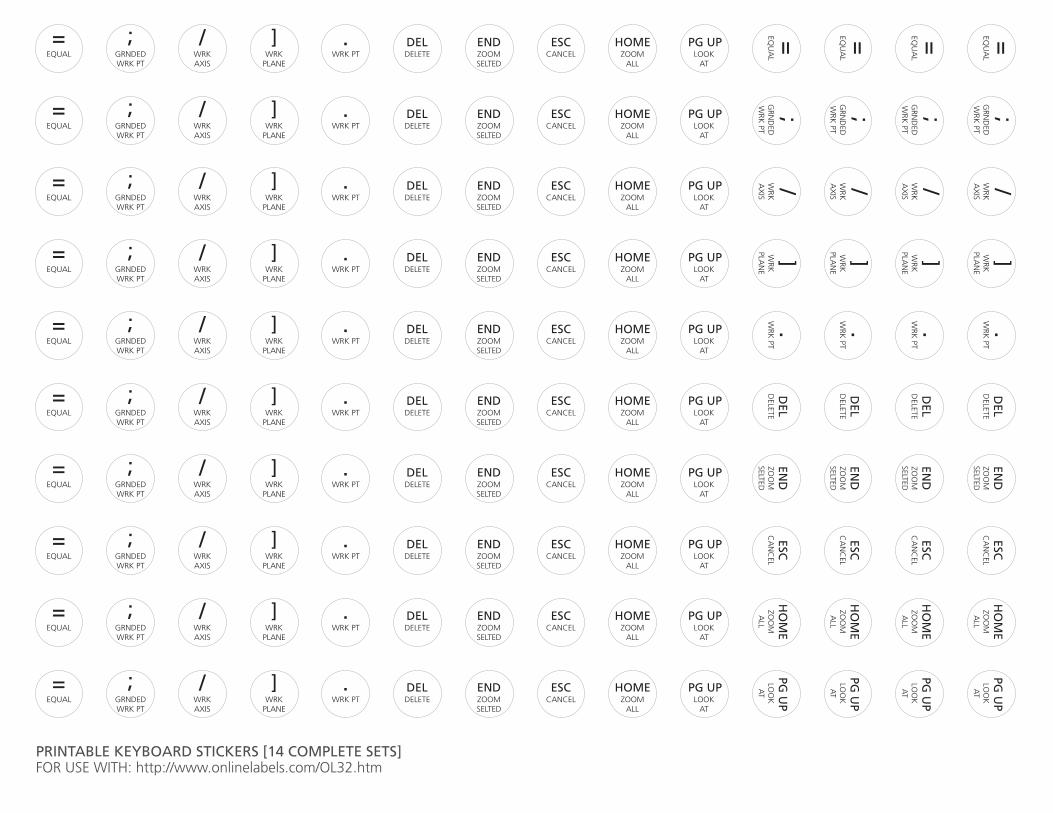
PRINTABLE KEYBOARD STICKERS [14 COMPLETE SETS]FOR USE WITH: http://www.onlinelabels.com/OL32.htm