Short Time Withstand 20kA_3s
24
Printed on 2008/05/27 n° 2005-0401-00 RAPPORT D'ESSAIS Released for Manufacturing
-
Upload
bombom-trinhphihai -
Category
Documents
-
view
241 -
download
3
Transcript of Short Time Withstand 20kA_3s
Printed on 2008/05/27
n° 2005-0401-00
RAPPORT D'ESSAIS
Released for Manufacturing

Printed on 2008/05/27
A2005-0401-00
TEST REPORT
No.
Released for Manufacturing

Printed on 2008/05/27
Grenoble le 15/04/2007
2005-0401-00
Environnement
Fonctionnel
Métrologie
PuissanceL2E Laboratoire d’Expertise et d’Essais
RAPPORT D'ESSAIS n°Appareil : Appareillage de boucle à haute tension
Désignation : MERLIN-GERIN RM6 type NE-IQI
Tension assignée 24 kV - Courant assigné 630 A - Fréquence assignée 50/60 Hz
Constructeur : SCHNEIDER ELECTRIC INDUSTRIES SAS - Rueil-Malmaison - FRANCE
Objet : Essai au courant de courte durée et à la valeur de crête du courant admissibles ducircuit principal assignés à :- 20 kA - 3 s - 50 kA crête - triphasé
Demandeur des essais : SCHNEIDER ELECTRIC
Date(s) des essais : 13/07/2005
Laboratoire d'essais : L2E – 38050 Grenoble - FRANCE
Les essais ont été faits suivant : La norme CEI 62271-200 (2003-11) § 6.6
Conclusion :
Résultats satisfaisants.
Le fonctionnement de l'appareil essayé et les résultats obtenus sont consignés dans les tableaux derésultats, oscillogrammes et photos ci-joints.La responsabilité de la conformité à l'appareil essayé, de tout appareil ayant la même désignation, incombeau Constructeur.
Ce rapportcontient :
12 Pages dont : 1 oscillogramme et 1 plan de l’appareil.
Le Responsable d’Essais Le Responsable Technique
La reproduction de ce rapport test n'est autorisée que sous forme de fac-similé photographique intégral. L’accréditation COFRAC attesteuniquement de la compétence du laboratoire pour les essais et analyses identifiées par un astérisque sur le présent document. Le COFRAC estsignataire de l’accord multilatéral de EA (European co-operation for Accreditation) et d’ILAC (International Laboratory Accreditation Cooperation)de reconnaissance de l’équivalence des rapports d’essais ou d’analyses.
R.ARNOULD B.BELLIA
L2E: Laboratoire d’Essais et d’Expertise - Schneider Electric Industries S.A.S - 37, Quai Paul Louis Merlin - F-38050 GRENOBLE Cedex 9Tel. +33 (0)4 76 57 93 37 - Fax +33 (0)4 76 57 99 38 - http://www.schneider-electric.com
ACCREDITATION N° 1-0140Portée
communiquéesur demande
Released for Manufacturing
Printed on 2008/05/27
A2005-0401-00
Grenoble 15/04/2007
Environment
Functional
Metrology
PowerL2E Expertise and Testing Laboratory
TEST REPORT No.Apparatus : High-voltage ring main unit
Designation : MERLIN-GERIN RM6 type NE-IQI
Rated voltage 24 kV - Rated normal current 630 A - Rated frequency 50/60 Hz
Manufacturer : SCHNEIDER ELECTRIC INDUSTRIES SAS - Rueil-Malmaison - FRANCE
Object : Test at short-time and peak withstand currents of the main circuit rated at :- 20 kA - 3 s - 50 kA peak - three-phase
Tested for : SCHNEIDER ELECTRIC
Date(s) of tests : 13/07/2005
Test laboratory : L2E – 38050 Grenoble - FRANCE
These tests were carried out in accordance with : Standard IEC 62271-200 (2003-11) § 6.6
Conclusion :
Satisfactory results.
The performance of the apparatus tested and the results obtained are shown in the tables, oscillograms andphotographs enclosed.The responsibility for conformity of any apparatus having the same designation with that tested rests withthe Manufacturer.
This reportcontains :
12 Pages with : 1 oscillogram and 1 drawing of the apparatus.
Test Manager Technical Manager
The reproduction of this test report is authorized only in the form of integral photographic facsimile. Accreditation COFRAC attests onlycompetence of the laboratory for the tests and analysis identified by an asterisk on this document. The COFRAC is signatory of the multilateralagreement of EA (European co-operation for Accreditation) and of ILAC (International Laboratory Accreditation Cooperation) of equivalencerecognition of test reports or analysis.
R.ARNOULD B.BELLIA
L2E: Expertise and Testing Laboratory - Schneider Electric Industries S.A.S - 37, Quai Paul Louis Merlin F-38050 GRENOBLE Cedex 9Tel. +33 (0)4 76 57 93 37 - Fax +33 (0)4 76 57 99 38 - http://www.schneider-electric.com
ACCREDITATION N° 1-0140
Scope on request
Released for Manufacturing

Printed on 2008/05/27
n° 2005-0401-00 page 2
- durée s : 3- barre de terre kA : 20- circuit de terre kA : 20- circuit principal kA : 20
- entre bornes de l’appareil ouvert kV : 145- à la terre et entre pôles kV : 125
- entre bornes de l’appareil ouvert kV : 60- à la terre et entre pôles kV : 50
Tension kV : 24
C R M 6 - 1 / a
CARACTERISTIQUES ASSIGNEES DE L’APPAREILLAGE
DE BOUCLE A HAUTE TENSION SELON CEI 62271-200
Constructeur : SCHNEIDER ELECTRICDésignation : MERLIN GERIN cellule RM6 type NE-IQI
Milieu de coupure gaz SF6 :Pression absolue à 20 °C bar : 1.2
Nombre de pôles : 3
Tension de tenue à fréquence industrielle (1 min)
Tension de tenue aux chocs de foudre
Fréquence Hz : 50/60
Courant en service continu A : 630
Courant de courte durée admissible
Degré de protection : IP3XC
Appareillage sous enveloppe métallique, composé de 3 cellules et équipé de :
- 2 interrupteurs à fréquence de manœuvres accrue avec sectionneurs de terre côté réseau.
- 1 combiné interrupteur-fusibles à fréquence de manœuvres accrue avec sectionneurs de terre en amont et en aval des fusibles
Suite page suivante
Released for Manufacturing

Printed on 2008/05/27
1-00 page 2No. A2005-040
- duration s : 3- earth bar kA : 20- earthing switch kA : 20- main circuit kA : 20
- accross open apparatus kV : 145- to earth and between poles kV : 125
- accross open apparatus kV : 60- to earth and between poles kV : 50
Voltage kV : 24
C R M 6 - 1 - A / a
RATINGS OF THE HIGH-VOLTAGE RING MAIN UNIT
ACCORDING TO IEC 62271-200
Manufacturer : SCHNEIDER ELECTRICDesignation : MERLIN GERIN cubicle RM6 type NE-IQI
Interrupting medium gas SF6 :Absolute pressure at 20°C bar : 1.2
Number of poles : 3
Power frequency withstand voltage (1 min)
Lightning impulse withstand voltage
Frequency Hz : 50/60
Normal current A : 630
Short-time withstand current
Degree of protection : IP3XC
Metal-enclosed switchgear, composed of 3 bays and equipped with :
- 2 increased operating frequency switches with earthing switches on the network side.
- 1 increased operating frequency switch-fuse combination with earthing switches upstream and downstream the fuses.
Continued
Released for Manufacturing
Printed on 2008/05/27
n° 2005-0401-00 page 3
- durée s : 3Courant de courte durée admissible kA : 20
- durée s : 3Courant de courte durée admissible kA : 20
- durée s : 3Courant de courte durée admissible kA : 20
C R M 6 - 2 / c
INTERRUPTEUR COTE RESEAU
Courant en service continu A : 630
Pouvoir de coupure- charge principalement active A : 630- boucle fermée de ligne de distribution A : 630- transformateur à vide A : ≤ 1 et 2 ≤ I ≤ 5- câbles à vide A : 31.5- lignes à vide A : /- en cas de défaut à la terre A : 95- câbles à vide et lignes à vide en cas de défaut terre A : 55
Pouvoir de fermeture en court-circuit kA crête : 62.5
Nombres de manoeuvres en charge principalement active : 100 C/O à In20 C/O à 5 % x In
SECTIONNEUR DE TERRE COTE RESEAU
Pouvoir de fermeture en court-circuit kA crête : 62.5
COMBINE INTERRUPTEUR-FUSIBLES COTE CHARGE
Courant en service continu A : 200
Pouvoir de coupure- charge principalement active A : 400- transformateur à vide A : ≤ 1 et 2 ≤ I ≤ 5
Pouvoir de coupure en court-circuit kA : 25Pouvoir de fermeture en court-circuit kA crête : 62.5
Nombres de manoeuvres en charge principalement active : 100 C/O à In20 C/O à 5 % x In
SECTIONNEUR DE TERRE EN AVAL DES FUSIBLES
Mécanisme de commande manuel :à accumulation d'énergie par ressort :
Courant de courte durée admissible kA : 2- durée s : 1
Pouvoir de fermeture en court-circuit kA crête : 5
Plan(s) n° : 51008475F0 ind.B0 folio 1/1
Released for Manufacturing

Printed on 2008/05/27
1-00 page 3No. A2005-040
- duration s : 3Short-time withstand current kA : 20
- duration s : 3Short-time withstand current kA : 20
- duration s : 3Short-time withstand current kA : 20
C R M 6 - 2 - A / c
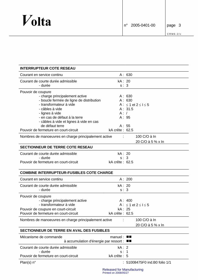
SWITCH ON THE NETWORK SIDE
Normal current A : 630
Breaking capacity- mainly active load A : 630- closed-loop distribution circuit A : 630- no-load transformer A : ≤ 1 and 2 ≤ I ≤ 5- cable-charging A : 31.5- line-charging A : /- earth fault A : 95- cable-and line-charging underearth faults A : 55
Short-circuit making current kA peak : 62.5
Number of operations with mainly active load : 100 C/O at In20 C/O at 5 % x In
EARTHING SWITCH ON THE NETWORK SIDE
Short-circuit making current kA peak : 62.5
SWITCH-FUSE COMBINATION ON THE LOAD SIDE
Normal current A : 200
Breaking capacity- mainly active load A : 400- no-load transformer A : ≤ 1 and 2 ≤ I ≤ 5
Short-circuit breaking current kA : 25Short-circuit making current kA peak : 62.5
Number of operations with mainly active load : 100 C/O at In20 C/O at 5 % x In
EARTHING SWITCH DOWNSTREAM THE FUSES
Operating mechanism manual :with spring stored energy :
Short-time withstand current kA : 2- duration s : 1
Short-circuit making current kA peak : 5
Drawing(s) No. : 51008475F0 rev.B0 sheet 1/1
Released for Manufacturing

Printed on 2008/05/27
n° 2005-0401-00 page 4
C R M 6 - 3 / a
DESCRIPTION DE L'APPAREILLAGE A SF6
SOUS ENVELOPPE METALLIQUE
L'appareillage sous enveloppe métallique est composé de 3 cellules, comme indiqué sur le schémaci-dessous.
3 2 1
1-3 : Interrupteurs 630 A et sectionneurs de terre côté réseau.
2 : Combiné interrupteur-fusibles 200 A et sectionneurs de terre côté charge.
Released for Manufacturing

Printed on 2008/05/27
No. A2005-0401-00 page 4
C R M 6 - 3 - A / a
DESCRIPTION OF SF6
METAL-ENCLOSED SWITCHGEAR
The SF6 metal-enclosed switchgear is made of 3 functional bays as shown on the plan below.
3 2 1
1-3 : Switches 630 A and earthing switches on network side.
2 : Switch-fuse combination 200 A and earthing switches on load side.
Released for Manufacturing

Printed on 2008/05/27
n° 2005-0401-00 page 5
L H 1 / a
LISTE DES ESSAIS EFFECTUES
Appareil n° : RM6 113
Type et séquence d’essai Page
Essai au courant de courte durée et à la valeur de crête du courant admissibles ducircuit principal à : 9- 20.8 kA -1 s - 51.8 kA crête - triphasé
Mesure de la résistance du circuit principal avant et après essai 10
Représentant(s)du constructeur : M. RIVAL SCHNEIDER ELECTRIC
Released for Manufacturing

Printed on 2008/05/27
1-00 page 5No. A2005-040
L H 1 - A / a
RECORD OF PROVING TESTS
Apparatus No. : RM6 113
Test type and test-duty Page
Test at short-time and peak withstand currents of main circuit at : 9- 20.8 kA - 1 s - 51.8 kA peak - three-phase
Measurement of the resistance of the main circuit before and after test 10
ManufacturerRepresentative(s) : Mr RIVAL SCHNEIDER ELECTRIC
Released for Manufacturing

Printed on 2008/05/27
n° 2005-0401-00 page 6
C D V 1 / a
CIRCUIT D’ESSAIS
alternateuralternator
enclencheurmakingswitch
élément deréglageadjustable circuit
transformateurde puissancepowertransformer
appareil en essaiapparatus under test
disjoncteurde protectionprotectioncircuit-breaker
CONDITIONS DES ESSAIS
- Alimentation par câbles de 240 mm2 en cuivre.- Alimentation par la fonction 1, court-circuit sur la fonction 3.- Interrupteurs des fonctions 1 et 3 : fermés.- Interrupteur de la fonction 2 : ouvert.- Voir schéma page suivante.
Released for Manufacturing
Printed on 2008/05/27
1-00 page 6No. A2005-040
C D V 1 - A / a
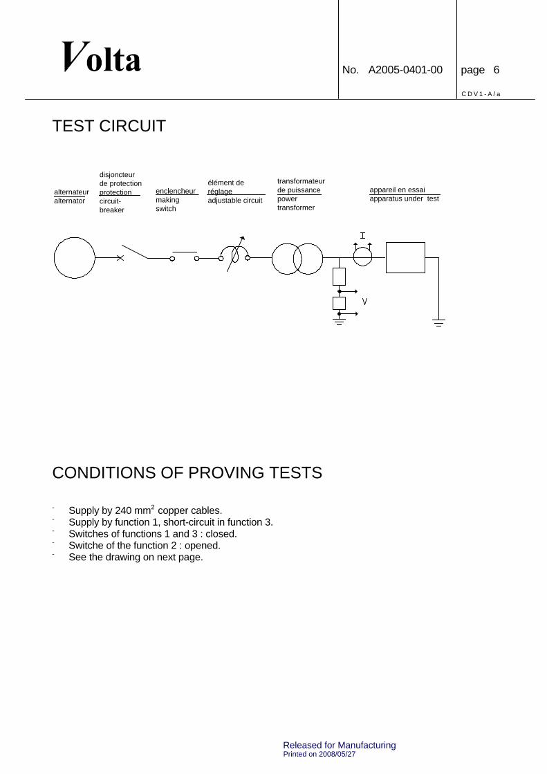
TEST CIRCUIT
alternateuralternator
enclencheurmakingswitch
élément deréglageadjustable circuit
transformateurde puissancepowertransformer
appareil en essaiapparatus under test
disjoncteurde protectionprotectioncircuit-breaker
CONDITIONS OF PROVING TESTS
- Supply by 240 mm2 copper cables.- Supply by function 1, short-circuit in function 3.- Switches of functions 1 and 3 : closed.- Switche of the function 2 : opened.- See the drawing on next page.
Released for Manufacturing

Printed on 2008/05/27
n° 2005-0401-00 page 7
C D V 2 / a
CONDITIONS DES ESSAIS
Court-circuit triphaséThree-phase short-circuit
Vue de faceFront view
AlimentationSupply
Released for Manufacturing

Printed on 2008/05/27
No. A2005-0401-00 page 7
C D V 2 - A / a
CONDITIONS OF PROVING TESTS
Court-circuit triphaséThree-phase short-circuit
Vue de faceFront view
AlimentationSupply
Released for Manufacturing

Printed on 2008/05/27
n° 2005-0401-00 page 8
I N C P / e
INCERTITUDES DES CHAINES DE MESURESIncertitude
Type de mesure Gamme Type de calcul totale (2σ)en %
Courant par shunt 0 - 5 A Valeur efficace vraie 1.15
Courant par shunt 0 - 5 A Valeur crête 1.07
Courant par shunt > 5 A Valeur efficace vraie 1.65
Courant par shunt > 5 A Valeur crête 1.60
Courant par sonde 0 - 65 A Valeur efficace vraie 1.15de courant
Courant par tore > 100 A Valeur efficace vraie 1.28
Courant par tore > 100 A Valeur efficace (crête à crête / √8) 1.67
Courant par tore > 100 A Valeur crête 1.20
Courant par tore > 100 A Intégrale de jouleEquivalent thermique
2.561.28
Courant par tore > 100 A Moyenne quadratique 3.34(crête à crête / √8)
Facteur de puissance > 100 A Rapport des crêtes 2.69
Tension par DC ou DCM ≤ 1000 V Valeur efficace vraie 1.08
Tension par DC ou DCM ≤ 1000 V Valeur efficace (crête à crête / √8) 1.42
Tension par DC ou DCM ≤ 1000 V Valeur crête 0.98
Tension par DC ou DCM ≥ 1000 V Valeur efficace vraie < 20 kHz 1.61et < 10 kV > 20 kHz 1.42
Tension par DC ou DCM ≥ 1000 V Valeur efficace < 20 kHz 1.93et < 10 kV (crête à crête / √8) > 20 kHz 1.79
Tension par DC ou DCM ≥ 1000 V Valeur crête < 20 kHz 1.55et < 10 kV > 20 kHz 1.35
Tension par DC ou DCM ≥ 10 kV Valeur efficace vraie < 20 kHz 1.61> 20 kHz 3.08
Tension par DC ou DCM ≥ 10 kV Valeur efficace < 20 kHz 1.93(crête à crête / √8) > 20 kHz 3.27
Tension par DC ou DCM ≥ 10 kV Valeur crête < 20 kHz 1.55> 20 kHz 3.05
Tension d’arc par DC ou DCM < 1000 V Valeur crête 1.55
Energie d’arc mesurée U ≥ 10 kV Valeur efficace vraie 2.35par DC ou DCM I mesuré par
TORE > 100 A
Pression 0.5 à 1 bar Valeur crête 4.151 à 2 bars 2.752 à 5 bars 2.105 à 10 bars 1.72
Temps 10 à 200 ms ≈ 3
Temps 200 ms à 16 s ± 10 ms
DC : diviseur capacitif DCM : diviseur capacitif mixte
Released for Manufacturing

Printed on 2008/05/27
1-00 page 8No. A2005-040
I N C P - A / e
UNCERTAINTIES OF MEASURING CHAINSTotal
Type of measurement Range Type of calculation uncertainty(2σ) in %
Current from shunt 0 - 5 A True r.m.s. value 1.15
Current from shunt 0 - 5 A Peak value 1.07
Current from shunt > 5 A True r.m.s. value 1.65
Current from shunt > 5 A Peak value 1.60
Current from pulse current 0 - 65 A true r.m.s. value 1.15transformer
Current from tore > 100 A True r.m.s. value 1.28
Current from tore > 100 A r.m.s. value (peak to peak / √8) 1.67
Current from tore > 100 A Peak value 1.20
Current from tore > 100 A Joule integralThermal current equivalent
2.561.28
Current from tore > 100 A Quadratic average 3.34(peak to peak / √8)
Power factor > 100 A Peak ratio 2.69
Voltage from CD or MCD ≤ 1000 V True r.m.s. value 1.08
Voltage from CD or MCD ≤ 1000 V r.m.s. value (peak to peak / √8) 1.42
Voltage from CD or MCD ≤ 1000 V Peak value 0.98
Voltage from CD or MCD ≥ 1000 V True r.m.s. value < 20 kHz 1.61and < 10 kV > 20 kHz 1.42
Voltage from CD or MCD ≥ 1000 V r.m.s. value < 20 kHz 1.93and < 10 kV (peak to peak / √8) > 20 kHz 1.79
Voltage from CD or MCD ≥ 1000 V Peak value < 20 kHz 1.55and < 10 kV > 20 kHz 1.35
Voltage from CD or MCD ≥ 10 kV True r.m.s. value < 20 kHz 1.61> 20 kHz 3.08
Voltage from CD or MCD ≥ 10 kV r.m.s. value < 20 kHz 1.93(peak to peak / √8) > 20 kHz 3.27
Voltage from CD or MCD ≥ 10 kV Peak value < 20 kHz 1.55> 20 kHz 3.05
Arc voltage from CD or MCD < 1000 V Peak value 1.55
Arc energy measured U ≥ 10 kV True r.m.s. value 2.35from CD or MCD I measured with
TORE > 100 A
Pressure 0.5 to 1 bar Peak value 4.151 to 2 bars 2.752 to 5 bars 2.105 to 10 bars 1.72
Time 10 to 200 ms ≈ 3
Time 200 ms to 16 s ± 10 ms
CD : capacitive divider MCD : mixed capacitive divider
Released for Manufacturing

Printed on 2008/05/27
n° 2005-0401-00 page 9
R D U R E M / b
RESULTATS DES ESSAIS AU COURANT DE
COURTE DUREE ADMISSIBLE
Appareil en essai : Cellule RM6 type NE-IQI
Conditions des essais : Voir pages 6 à 8
Etat de l’appareil avant essais : - neuf :- ayant subi les essais précédents :
Oscillogramme n° 20050373.
0005
Courant de crête kA 51.8 40.7 41.8
Courant début kA 22.0 22.3 21.7
(valeur efficace) fin kA 19.8 20.5 20.0
Moyenne quadratique kA 20.8
Durée du courant s 3.01
Intégrale de I2dt 106A2s 1288 1359 1276
Equivalent thermique kA 20.8
Durée s 3
Etat de l’appareil après essais : Aucune détérioration n’a été constatée,L’appareil manoeuvre normalement.
Released for Manufacturing

Printed on 2008/05/27
1-00 page 9No. A2005-040
R D U R E M - A / b
RESULTS OF THE SHORT-TIME
WITHSTAND CURRENT TESTS
Apparatus under test : Cubicle RM6 type NE-IQI
Test conditions : See pages 6 to 8
Apparatus condition before tests : - new :- having performed the previous tests :
Oscillogram No. 20050373.
0005
Peak current kA 51.8 40.7 41.8
Current initial kA 22.0 22.3 21.7
(r.m.s. value) final kA 19.8 20.5 20.0
Quadratic average kA 20.8
Current duration s 3.01
I2dt integral 106A2s 1288 1359 1276
Thermal equivalent kA 20.8
Duration s 3
Apparatus condition after tests : No deterioration was noted,The apparatus operates normally.
Released for Manufacturing
n° 2005-0401-00 page 10
Printed on 2008/05/27
R R 1 / a
MESURE DE LA RESISTANCE
DE L'APPAREIL
Appareil en essais : Circuit principal
Mesure de la chute de tension en mV sous 100 Adc
Pôle 1 2 3
Avant essais 74.0 76.0 77.0
Après essais 63.0 68.0 67.0
Ratio après/avant 0.85 0.89 0.87
Résultats satisfaisants : Augmentations des chutes de tension inférieures à 20 %
Released for Manufacturing

Printed on 2008/05/27
No. A2005-0401-00 page 10
R R 1 - A / a
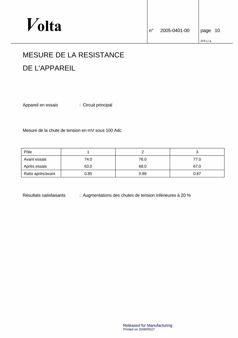
MEASUREMENT OF THE RESISTANCE
OF THE APPARATUS
Apparatus under test : Main circuit
Measurement of the voltage drop in mV at 100 Adc
Pole 1 2 3
Before tests 74.0 76.0 77.0
After tests 63.0 68.0 67.0
Ratio after/before 0.85 0.89 0.87
Satisfactory results : Increases of the voltage drops below 20 %
Released for Manufacturing

Printed on 2008/05/27
0,00
és
3,20
s
100,
00 m
s
128,
00 m
s/cm
VO
LTA
20
0503
73 -
000
5C
ATI
E V
.1.5
.3.1
29 p
age
001
Effe
ctue
le 1
3/07
/200
5 12
:03:
12E
dite
le 1
0/07
/200
6 12
:00:
53
I120
,00
kA/c
m
I220
,00
kA/c
m
I320
,00
kA/c
m
V1
100,
00 V
/cm
V2
100,
00 V
/cm
V3
100,
00 V
/cm
Released for Manufacturing