
Short Circuit Current Level Control
14
Short Circuit Current Level Control and its Effects on Circuit Breakers Transient Studies M. Khorrami*, Mohammad S. Nader**, N. Khalil Nejhad* * Islamic Azad University, Science & Research Branch, Tehran, Iran e-mail: [email protected] ** University of New South Wales, Sydney, Australia e-mail: [email protected] * Islamic Azad University, Science & Research Branch, Tehran, Iran e-mail: [email protected] Submitted: 12/01/2010 Accepted: 06/02/2010 Appeared: 16/02/2010 HyperSciences.Publisher Abstract— Increase in demand and ever-increasing expansion of interconnected power networks lead to increase in short circuit levels higher than interrupting rating of power circuit breakers and other pertinent equipments. In this study, planned expansion of Iran Electric Power Network for 2013 is considered. A few substations such as FiruzBahram substation in Tehran Regional Electric Company have been experiencing the over mentioned problem for long time. Firstly, necessity of fault current limiter utilization in substations which face high short circuit current levels has been investigated. Then, considering infrastructure and condition of the substation, number of practically applicable methods are employed to control and reduce short circuit level and a suitable method is selected on the base of maximum reduction rate of fault current range after limiting as well as minimum variation rate of bus voltage and active power losses and static stability limit in Tehran Regional Electric Power Network. At the end, the most suitable configurations which provide maximum fault current limitation and has minimum effect on load flow results have been compared in regards to switching transient over voltage. All simulations were carried out utilizing DigSilent software package and results showed that the final selected method is able to limit fault current level down to nominal interrupting level of circuit breakers and TRV will have desired condition. Keywords: Short circuit level, Fault current limiter, Bus split, Current limiter reactor(CLR), Interphase power controller(IPC), Phase shifter transformer(PST), Transient Recovery Voltage(TRV), Rate of Rise of Recovery Voltage(R.R.R.V) 1. INTRODUCTION One of the challenges that power system operators and owners are facing on a daily manner is increased fault current level in power transmission substations compared to nominal interrupting level of circuit breakers and their pertinent equipments. This has been occurred as a result of power transmission system expansion. Replacing the existing switchgears and continuous upgrade to reach higher nominal interrupting level in addition to their excessive expenses, needs network redesign and test of all power transmission equipments in order to achieve acceptable network reliability and security levels. Therefore, many researchers have investigated these issues since beginning of the 1970 th to make adjustment on short circuit levels by employing fault current limiters. Mechanism of fault current limiter methods is to show low impedance during normal operation mode and very high impedance against fault current in order to prevent current amplitude increasing process which might lead to equipment damage. Main difference among limiters is only in their performance and how they enter into and exit impedance from the circuit (Eidiani, Shanechi and Ameli, 2006, Javadi, 2005, Wu, Jenkine, Goran, Jim and Catheine, 2004). Short circuit level reduction methods can be divided into two major active and inactive groups (Schmitt, Amon, Braun and Damstra, 2005). In inactive method, network impedance is increased in normal and fault operation modes, while in active method; network impedance is increased only when fault occurs. Inactive methods also are divided into structural and instrumental methods. Using inactive methods might lead to increased network losses in normal operation mode. Therefore, load flow and transient stability analysis shall be investigated to assure the network is working under standard conditions. Active methods have not been used extensively in the industry yet because of their high cost, complexity, voltage limitation, operation current and creating the transient states in the network. Some methods for limiting fault current are as below: 1. Bus spilt (Lee, Lee, Yoon and Hyunm, 2006, Wu, Mutale, Jenkins and Strbac, 2003) Journal of Electrical Engineering: Theory and Application (Vol.1-2010/Iss.1) Khorrami et al. / Short Circuit Current Level Control and its Effects on Circuit … / pp. 4-17 Copyright © 2010 HyperSciences_Publisher. All rights reserved 4 www.hypersciences.org
-
Upload
mshahidshaukat -
Category
Documents
-
view
52 -
download
8
description
Short Circuit Current Level Control andits Effects onCircuit Breakers Transient Studies
Transcript of Short Circuit Current Level Control
Short Circuit Current Level Control and its Effects on
Circuit Breakers Transient Studies
M. Khorrami * , Mohammad S. Nader** , N. Khalil Nejhad*
* Islamic Azad University, Science & Research Branch, Tehran, Iran e-mail: [email protected]
** University of New South Wales, Sydney, Australia e-mail: [email protected]
* Islamic Azad University, Science & Research Branch, Tehran, Iran e-mail: [email protected]
Submitted: 12/01/2010Accepted: 06/02/2010Appeared: 16/02/2010HyperSciences.Publisher
Abstract— Increase in demand and ever-increasing expansion of interconnected power networks lead to increase in short circuit levels higher than interrupting rating of power circuit breakers and other pertinent equipments. In this study, planned expansion of Iran Electric Power Network for 2013 is considered. A few substations such as FiruzBahram substation in Tehran Regional Electric Company have been experiencing the over mentioned problem for long time. Firstly, necessity of fault current limiter utilization in substations which face high short circuit current levels has been investigated. Then, considering infrastructure and condition of the substation, number of practically applicable methods are employed to control and reduce short circuit level and a suitable method is selected on the base of maximum reduction rate of fault current range after limiting as well as minimum variation rate of bus voltage and active power losses and static stability limit in Tehran Regional Electric Power Network. At the end, the most suitable configurations which provide maximum fault current limitation and has minimum effect on load flow results have been compared in regards to switching transient over voltage. All simulations were carried out utilizing DigSilent software package and results showed that the final selected method is able to limit fault current level down to nominal interrupting level of circuit breakers and TRV will have desired condition.
Keywords: Short circuit level, Fault current limiter, Bus split, Current limiter reactor(CLR), Interphase power controller(IPC), Phase shifter transformer(PST), Transient Recovery Voltage(TRV), Rate of Rise of Recovery Voltage(R.R.R.V)
1. INTRODUCTION
One of the challenges that power system operators and owners are facing on a daily manner is increased fault current level in power transmission substations compared to nominal interrupting level of circuit breakers and their pertinent equipments. This has been occurred as a result of power transmission system expansion. Replacing the existing switchgears and continuous upgrade to reach higher nominal interrupting level in addition to their excessive expenses, needs network redesign and test of all power transmission equipments in order to achieve acceptable network reliability and security levels. Therefore, many researchers have investigated these issues since beginning of the 1970th to make adjustment on short circuit levels by employing fault current limiters.
Mechanism of fault current limiter methods is to show low impedance during normal operation mode and very high impedance against fault current in order to prevent current amplitude increasing process which might lead to equipment damage. Main difference among limiters is only in their performance and how they enter into and exit impedance
from the circuit (Eidiani, Shanechi and Ameli, 2006, Javadi, 2005, Wu, Jenkine, Goran, Jim and Catheine, 2004).
Short circuit level reduction methods can be divided into two major active and inactive groups (Schmitt, Amon, Braun and Damstra, 2005). In inactive method, network impedance is increased in normal and fault operation modes, while in active method; network impedance is increased only when fault occurs. Inactive methods also are divided into structural and instrumental methods.
Using inactive methods might lead to increased network losses in normal operation mode. Therefore, load flow and transient stability analysis shall be investigated to assure the network is working under standard conditions. Active methods have not been used extensively in the industry yet because of their high cost, complexity, voltage limitation, operation current and creating the transient states in the network.
Some methods for limiting fault current are as below: 1. Bus spilt (Lee, Lee, Yoon and Hyunm, 2006, Wu,
Mutale, Jenkins and Strbac, 2003)
Journal of Electrical Engineering: Theory and Application (Vol.1-2010/Iss.1)Khorrami et al. / Short Circuit Current Level Control and its Effects on Circuit … / pp. 4-17
Copyright © 2010 HyperSciences_Publisher. All rights reserved 4 www.hypersciences.org
2. Exit lightly loaded lines which are effective on reduction of fault current (Eidiani, Shanechi and Ameli, 2006, Wu, Jenkine, Goran, Jim and Catheine, 2004)
3. Open network loops (Pouraghababa, Eghtedarnia and Karimi Iranian, 2007)
4. Fault current limiting reactors (Lee, Lee, Yoon andHyun, 2006, Wu, Mutale, Jenkins and Strbac, 2003)
5. Increase in impedance percentage of transformer ( Rubenbauer and Herold, 2006)
6. Impedance type fault current limiters with mechanical switches (Daisuke, Hirotaka, Yasunobu and Masuo, 2006, Wu, Jenkine, Goran, Jim and Catheine, 2004)
7. Fault current limiters that use fuses (Doazhuo, Lu and Wu, 2004)
8. Superconducting fault current limiters (Meyer and Doncker, 2006, Wu, Mutale, Jenkins and Strbac, 2003)
9. Impedance type limiters and resonant circuits that use thyristor switches (Chen and Jiang, 2004, Meyer andDoncker, 2006)
10. Interphase power controllers (Acha and Esquivel, 1997, Beaurega, Brochu, Morin and Pelletier, 1994,Brochu, Beauregard, Morin, Lamay, Pelletier and Kheir, 1998, Farmad, Farhangi, Afsharnia and Gharehetian, 2006)
11. Fault current limiters that use resistors sensitive to temperature (Schmitt, 2006)
2. PROBLEM DEFINITION
Fault current analyzing indicates that three-phase and single- phase fault currents mostly flow in the exact fault location.
Generators that generate fault currents or feeders connected to a bus by which the fault current is provided, each one consists of less values of calculated fault current in the bus. This current is always less than interrupt rating of the embedded switches, unless with the faults which occur close to bus and at the beginning of feeder, exactly after power switch. Fault current magnitude of this type of faults is approximately equal to fault current of the bus and interrupt rating of the switches usually are determined according to this current (Calixte, Yokomizu, Shimizu, Matsumure and Fujita, 2004, Javadi, 2005). Expansion of network and power stations in Iran is considered until 2013 based on 10 percent increase in average annual demand in energy generation and transmission networks. According to the calculation of short circuit in 400kV and 230kV Tehran grid via DigSilent software package by the end of 2013, a few numbers of substations in this area have fault current more than CB rated interrupting level.
Table 1 and Table 2 indicate 230kV and 400 kV Tehran's substations in 2013 which sequence value of three-phase and single-phase short circuit current is more than installed switch rating.
As it can be seen, 230kV FiruzBahram substation has the worst situation while three-phase or single-phase short circuit occurs among Tehran's critical substations and employing fault current limiter seems to be necessary in this substation.
Table 1. Tree-phase short circuit of Tehran's critical substations
IS.C – ICB
[kA] Rated interrupting current of
Circuit-Breaker [kA]Fault current
[kA] Rated Voltage
[kV]Substation
21.46 40 61.46 230 FiruzBahram
17.40 31.5 48.90 230 MontazerQaem
10.67 40 50.67 230 MontazerQaemCC
10.25 40 50.25 230 ReyGas
5.49 25 30.49 230 Besat
3.61 40 43.61 230 ToffBesat
2.40 40 42.40 230 ShushTeh
Table 2. Single-phase short circuit of Tehran's critical substations
IS.C -ICB
[kA] Rated interrupting current of
Circuit-Breaker [kA] Fault current
[kA] Rated Voltage
[kV]Substation
17.79 31.5 49.46 230 MontazerQaem
13.57 40 53.57 230 MontazerQaemCC
12.45 40 52.45 230 FiruzBahram
11.47 40 51.47 230 ReyGas
2.76 50 52.76 400 DamavandCC
2.05 25 27.05 230 Besat
0.32 50 50.32 400 Jalal
Journal of Electrical Engineering: Theory and Application (Vol.1-2010/Iss.1)Khorrami et al. / Short Circuit Current Level Control and its Effects on Circuit … / pp. 4-17
5
3. NETWORK INDICES
In this study, a number of indices were considered such as variation rate of bus voltage and active power losses, variations of rotors from static stability limit, reduction rate of fault current range after limiting in order to investigate effect of each one of limiting methods on grid and comparing them with each other, so these indices have been stated as following relations:
3.1 Fault current limitation index
%)(
)()(
N
FCL N
iI
iIiIa
sc
scsci
−= (1)
n
aA
n
ii∑
== 1 (2)
Where iI sc )( N and iI sc )( FCL
are fault currents of bus i before
and after limitation. n is number of buses in Tehran transmission power network and ai is fault current limitation coefficient in each bus.
3.2 Voltage variation index
%)(
)()(
iV
iViVb
N
FCLNi
−= (3)
n
bB
n
ii∑
== 1 (4)
Where (VN)i and (VFCL)i are voltages of bus i before and after limitation. n is number of buses in Tehran transmission power network and bi is voltage variations coefficient in each bus.
3.3 Active power losses variation index
%)(
)()(
N
N
iP
iPiPc
loss
FCLlosslossi
−= (5)
N
cC
N
ii∑
== 1 (6)
Where iP Nloss )( and iP FCLloss )( are active power losses of
bus i before and after limitation. N is number of lines in
Tehran transient power network and ic is active power lose
variations coefficient in each bus.
3.4 Static stability limit index
%90
)(90 FCL
id
sc
i
α−= (7)
m
dD
m
ii∑
== 1 (8)
Where isc )( FCL α is maximum angle of rotor i after
limitation and short circuit occurrence. m is number of
generators in Tehran transmission power network andic is
rotor angular variation coefficient in each bus.
3.5 Equation (9) shows dominant index for fault current limiting method obtained from algebraic addition of above described indices.
DCBAE λγβα ++−= (9)
Where λγβα ,,, coefficients are positive and their value are
selected in order to proportionate effects on indexes.
4. SUGGESTED PRACTICAL METHODS TO REDUCE SHORT CIRCUIT CURRENT LEVEL IN FIUZBAHRAM
SUBSTATION
Among the mentioned limiting methods in section 2, suggested methods considering their practically applicability, minimum required equipments, least harmonic effects, availability of the required equipment and prices for FiruzBahram substation are bus split, CLR and low loaded lines exit, which are effective to reduce fault current level with as well as IPC.
Applied methods according to their execution way; active or inactive; have been listed below.
It is notable that selection and execution of the methods will be totally dependent on special structure of each substation that will be explained in detail next.
1. Bus split in length inactively (by opening bus-section ) 2. Bus split in width inactively (by opening bus-coupler) 3. Bus split in length and width inactively 4. Series reactor in length in bus-section inactively 5. Series reactor in width in bus-coupler inactively 6. Series reactor in length and in width in bus-section and bus-coupler inactively 7. Exit of lightly loaded line and effective on fault current limiting inactively 8. Bus split in length immediately after fault occurrence and before opening the switch actively 9. Bus split in width actively 10. Bus split in length and in width actively 11. Series reactor in length in bus-section actively 12. Series reactor in width in bus-coupler actively13. Series reactor in length and in width in bus-section and bus-coupler place actively 14. Opening low loaded line which is effective on fault current reduction actively 15. Interphase power controller
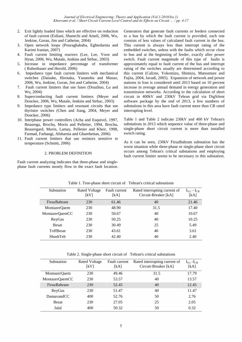
As it can be seen in Fig.1, bus configuration in 230kV FiruzBahram substation is double type. In this configuration, two major buses are used that each one of these buses can be operated as reserve for the other. Since number of branches on 230kV bus in FiruzBahram substation is high, in order to increase reliability permanent servicing and increase the maneuver on this bus, two bus-sections have been used for longitudinal division and two bus couplers have been used
Journal of Electrical Engineering: Theory and Application (Vol.1-2010/Iss.1)Khorrami et al. / Short Circuit Current Level Control and its Effects on Circuit … / pp. 4-17
6
for widthwise division of bus, that every four breakers are closed in normal mode and can be interrupted under load. Considering the arrangement of this substation, all suggested 15 methods for limiting are practical in this substation.
Fig. 1. FiruzBahram single-line diagram
5. INVESTIGATION OF THE SUGGESTED SOLUTIONS AND DETERMINATION OF METHODS PRIORITY FOR
FIRUZBAHRAM SUBSTATION
5.1 Bus split
According Fig.1 in FiruzBahram substation, bus split can be in length and in width because of bus-sections and bus-couplers can be interrupted under load. Also this method can be executed actively or inactively.
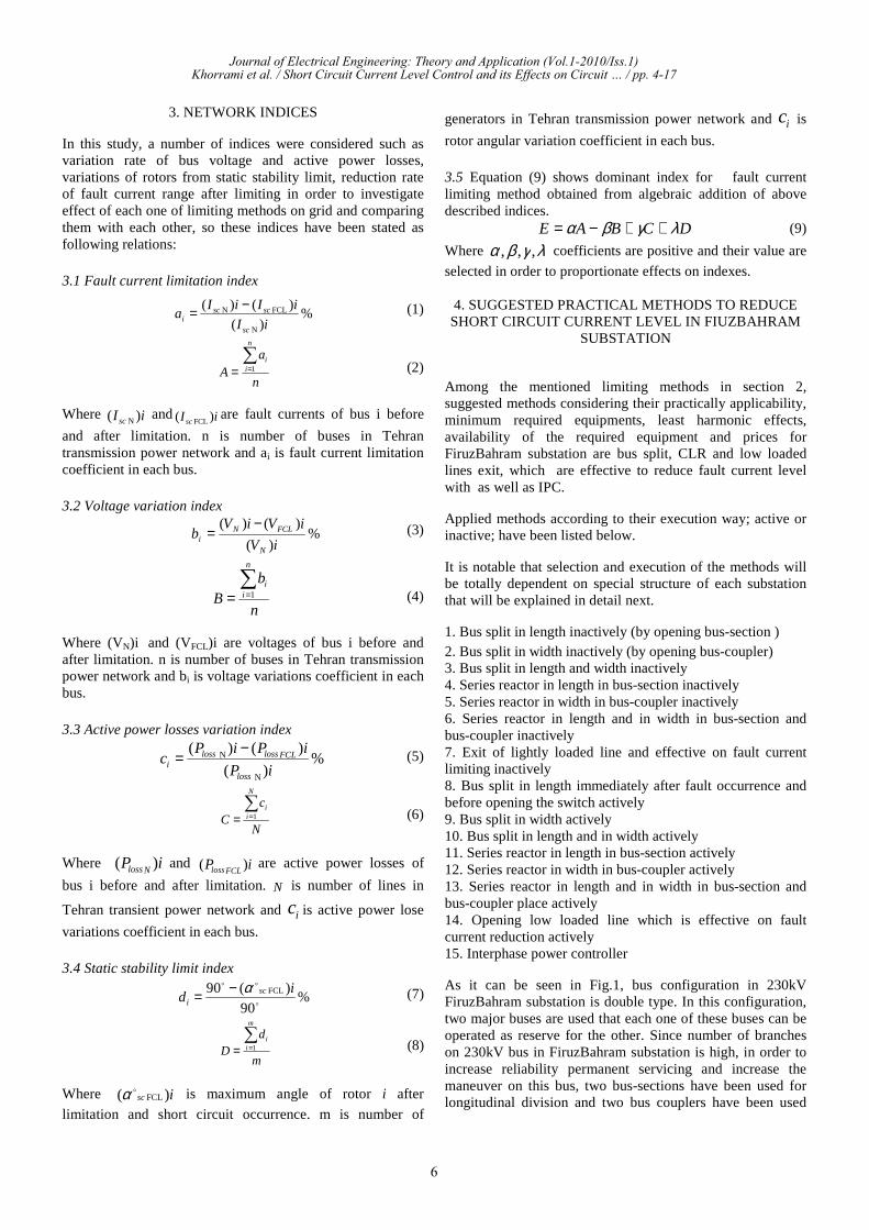
For example, fig.2 shows bus split in length and width by open bus-sections and bus-couplers of FiruzBahram substation. Table 3 indicates value three-phase short circuit current of FiruzBahram buses after executing this method.
Fig. 2. FiruzBahram single-line diagram after bus split
Table 3. Three-phase fault current in FiruzBahram buses [kA]
Bus 2/2
Bus 2/1
Bus 1/2
Bus 1/1
Method
29.5144.4929.5144.49Bus split in length41.9241.9249.9549.95Bus split in width30.128.2543.1225.15Bus split in length and
width
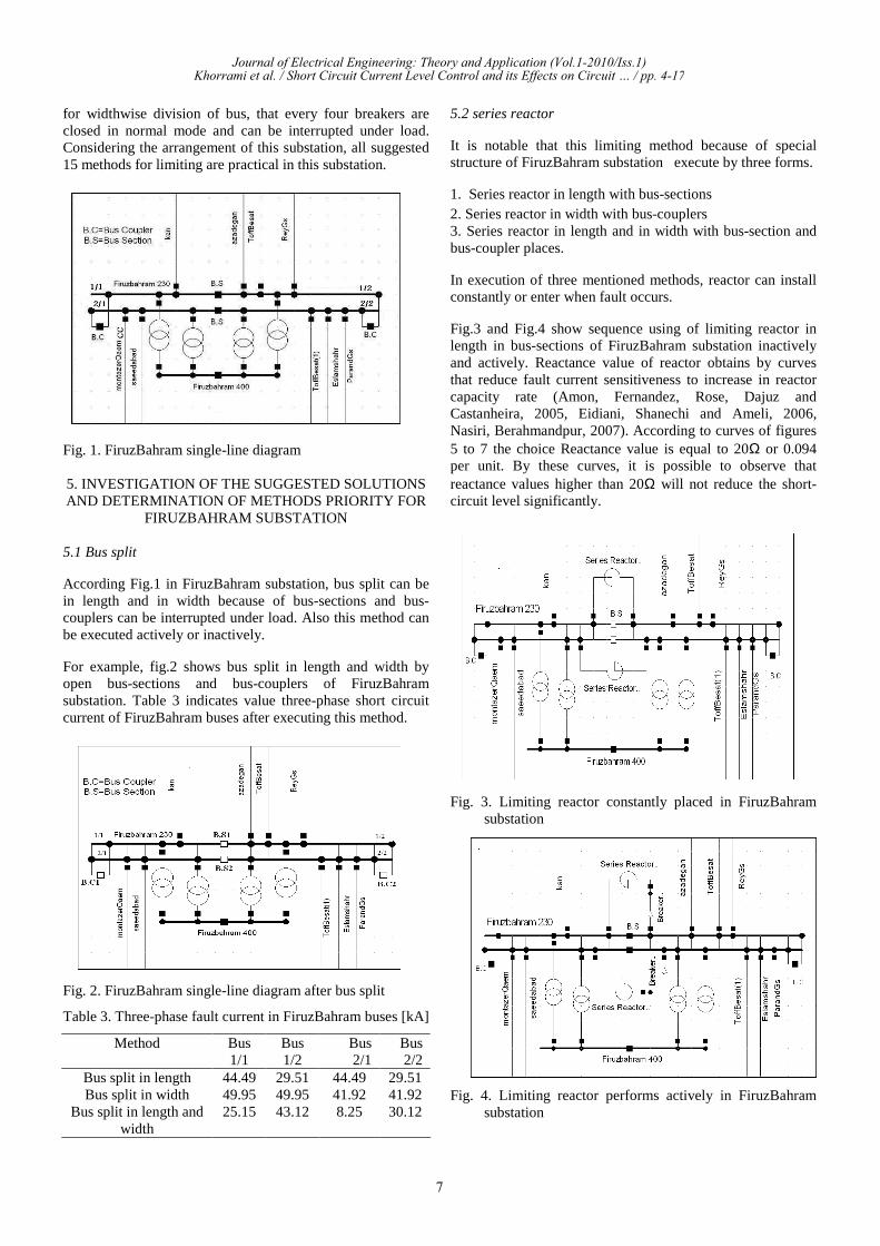
5.2 series reactor
It is notable that this limiting method because of special structure of FiruzBahram substation execute by three forms.
1. Series reactor in length with bus-sections 2. Series reactor in width with bus-couplers 3. Series reactor in length and in width with bus-section and bus-coupler places.
In execution of three mentioned methods, reactor can install constantly or enter when fault occurs.
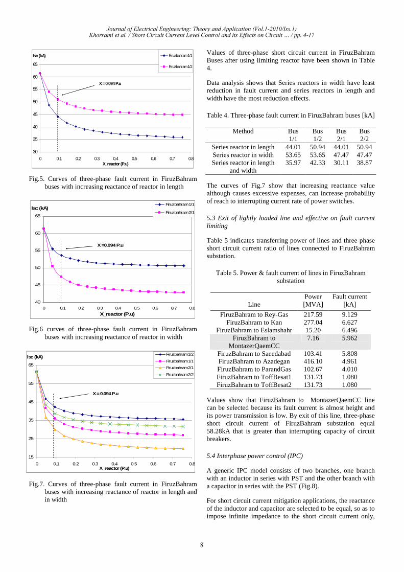
Fig.3 and Fig.4 show sequence using of limiting reactor in length in bus-sections of FiruzBahram substation inactively and actively. Reactance value of reactor obtains by curves that reduce fault current sensitiveness to increase in reactor capacity rate (Amon, Fernandez, Rose, Dajuz and Castanheira, 2005, Eidiani, Shanechi and Ameli, 2006, Nasiri, Berahmandpur, 2007). According to curves of figures 5 to 7 the choice Reactance value is equal to 20Ω or 0.094 per unit. By these curves, it is possible to observe that reactance values higher than 20Ω will not reduce the short- circuit level significantly.
Fig. 3. Limiting reactor constantly placed in FiruzBahram substation
Fig. 4. Limiting reactor performs actively in FiruzBahram substation
Journal of Electrical Engineering: Theory and Application (Vol.1-2010/Iss.1)Khorrami et al. / Short Circuit Current Level Control and its Effects on Circuit … / pp. 4-17
7
30
35
40
45
50
55
60
65
0 0.1 0.2 0.3 0.4 0.5 0.6 0.7 0.8X_reactor (P.u)
Isc (kA) Firuzbahram 1/1
Firuzbahram 1/2
X = 0.094 P.u
Fig.5. Curves of three-phase fault current in FiruzBahram buses with increasing reactance of reactor in length
40
45
50
55
60
65
0 0.1 0.2 0.3 0.4 0.5 0.6 0.7 0.8
X_reactor (P.u)
Isc (kA)Firuzbahram 1/1
Firuzbahram 2/1
X =0.094 P.u
Fig.6 curves of three-phase fault current in FiruzBahram buses with increasing reactance of reactor in width
15
25
35
45
55
65
0 0.1 0.2 0.3 0.4 0.5 0.6 0.7 0.8X_reactor (P.u)
Isc (kA)Firuzbahram 1/2
Firuzbahram 1/1
Firuzbahram 2/1
Firuzbahram 2/2
X = 0.094 P.u
Fig.7. Curves of three-phase fault current in FiruzBahram buses with increasing reactance of reactor in length and in width
Values of three-phase short circuit current in FiruzBahram Buses after using limiting reactor have been shown in Table 4.
Data analysis shows that Series reactors in width have least reduction in fault current and series reactors in length and width have the most reduction effects.
Table 4. Three-phase fault current in FiruzBahram buses [kA]
Bus 2/2
Bus 2/1
Bus 1/2
Bus 1/1
Method
50.9444.0150.9444.01Series reactor in length47.4747.4753.6553.65Series reactor in width38.8730.1142.3335.97Series reactor in length
and width
The curves of Fig.7 show that increasing reactance value although causes excessive expenses, can increase probability of reach to interrupting current rate of power switches.
5.3 Exit of lightly loaded line and effective on fault current limiting
Table 5 indicates transferring power of lines and three-phase short circuit current ratio of lines connected to FiruzBahram substation.
Table 5. Power & fault current of lines in FiruzBahram substation
Line Power [MVA]
Fault current [kA]
FiruzBahram to Rey-Gas 217.59 9.129 FiruzBahram to Kan 277.04 6.627
FiruzBahram to Eslamshahr 15.20 6.496 FiruzBahram to
MontazerQaemCC 7.16 5.962
FiruzBahram to Saeedabad 103.41 5.808 FiruzBahram to Azadegan 416.10 4.961 FiruzBahram to ParandGas 102.67 4.010 FiruzBahram to ToffBesat1 131.73 1.080 FiruzBahram to ToffBesat2 131.73 1.080
Values show that FiruzBahram to MontazerQaemCC line can be selected because its fault current is almost height and its power transmission is low. By exit of this line, three-phase short circuit current of FiruzBahram substation equal 58.28kA that is greater than interrupting capacity of circuit breakers.
5.4 Interphase power control (IPC)
A generic IPC model consists of two branches, one branch with an inductor in series with PST and the other branch with a capacitor in series with the PST (Fig.8).
For short circuit current mitigation applications, the reactance of the inductor and capacitor are selected to be equal, so as to impose infinite impedance to the short circuit current only,
Journal of Electrical Engineering: Theory and Application (Vol.1-2010/Iss.1)Khorrami et al. / Short Circuit Current Level Control and its Effects on Circuit … / pp. 4-17
8
while controlling power flow under normal and post-contingency conditions. Therefore, for selection of suitable installation place and initial IPC values with proposed algorithm in (Farmad, Farhangi, Afsharnia and Gharehetian, 2006), firstly line with the most ratio of short circuit current is determined then obtained maximum power transmit of this line. According to fault current value of Table 5, location of IPC installation is FiruzBahram to Rey-Gas line.
Fig.8. Genetic single-line diagram of the Interphase power controller
Max power of this line is equal P=-213.59MW and equivalent network impedance seen by IPC is Zseen=10.87Ω.
To avoid resonance phenomenon, value of XA must meet XA > 10* Zseen XA>108.7Ω.
As IPC is used as a fault current limiter, it can be have one PST. So, active power in IPC terminal is obtained by using equation (10).
AX
P )sin(
2
ψ≈ (10)
Hence, value of angle ψ is selected ψ >25.96° with having
active power, reactance value and equation (10).
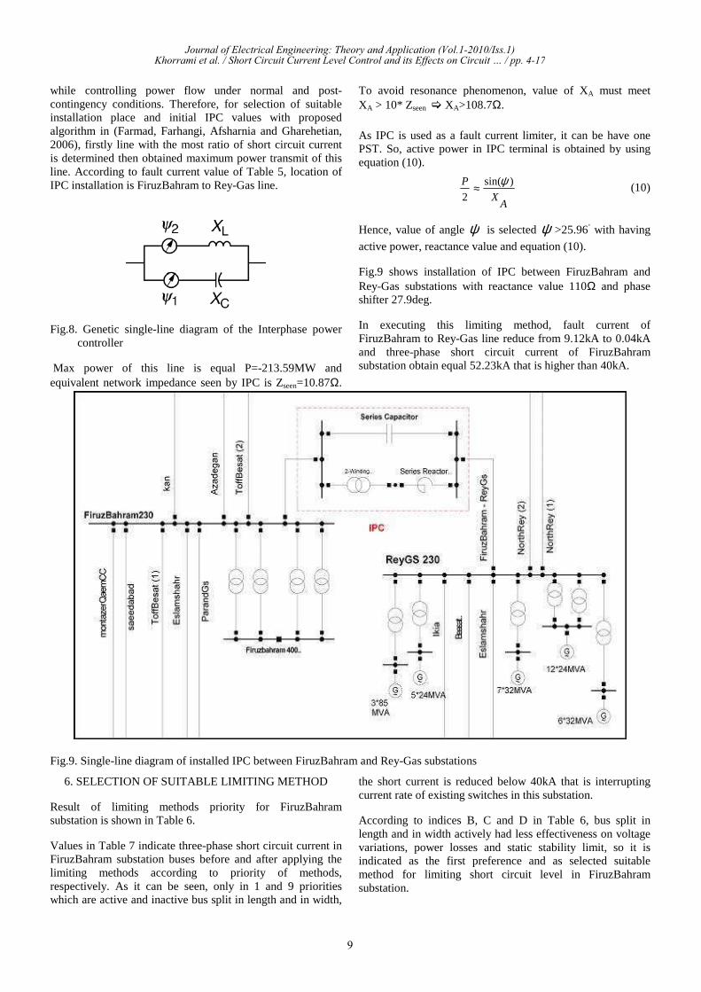
Fig.9 shows installation of IPC between FiruzBahram and Rey-Gas substations with reactance value 110Ω and phase shifter 27.9deg.
In executing this limiting method, fault current ofFiruzBahram to Rey-Gas line reduce from 9.12kA to 0.04kA and three-phase short circuit current of FiruzBahram substation obtain equal 52.23kA that is higher than 40kA.
Fig.9. Single-line diagram of installed IPC between FiruzBahram and Rey-Gas substations
6. SELECTION OF SUITABLE LIMITING METHOD
Result of limiting methods priority for FiruzBahramsubstation is shown in Table 6.
Values in Table 7 indicate three-phase short circuit current in FiruzBahram substation buses before and after applying the limiting methods according to priority of methods, respectively. As it can be seen, only in 1 and 9 priorities which are active and inactive bus split in length and in width,
the short current is reduced below 40kA that is interrupting current rate of existing switches in this substation.
According to indices B, C and D in Table 6, bus split in length and in width actively had less effectiveness on voltage variations, power losses and static stability limit, so it is indicated as the first preference and as selected suitable method for limiting short circuit level in FiruzBahram substation.
Journal of Electrical Engineering: Theory and Application (Vol.1-2010/Iss.1)Khorrami et al. / Short Circuit Current Level Control and its Effects on Circuit … / pp. 4-17
9
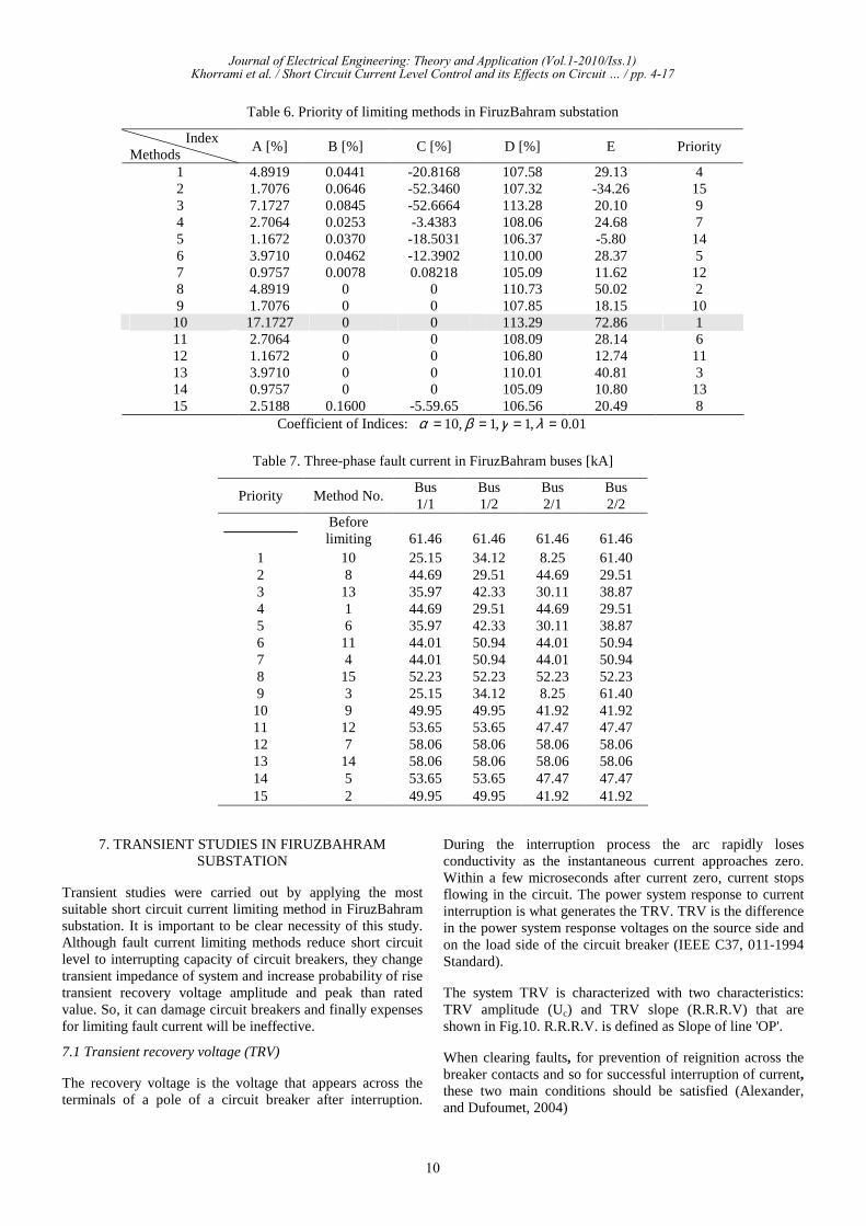
Table 6. Priority of limiting methods in FiruzBahram substation
Priority E D [%] C [%] B [%] A [%] Index
Methods4 29.13 107.58 -20.8168 0.0441 4.8919 1 15 -34.26 107.32 -52.3460 0.0646 1.7076 2 9 20.10 113.28 -52.6664 0.0845 7.1727 3 7 24.68 108.06 -3.4383 0.0253 2.7064 4 14 -5.80 106.37 -18.5031 0.0370 1.1672 5 5 28.37 110.00 -12.3902 0.0462 3.9710 6 12 11.62 105.09 0.08218 0.0078 0.9757 7 2 50.02 110.73 0 0 4.8919 8 10 18.15 107.85 0 0 1.7076 9 1 72.86 113.29 0 0 17.1727 10 6 28.14 108.09 0 0 2.7064 11 11 12.74 106.80 0 0 1.1672 12 3 40.81 110.01 0 0 3.9710 13 13 10.80 105.09 0 0 0.9757 14 8 20.49 106.56 -5.59.65 0.1600 2.5188 15
Coefficient of Indices: 01.0,1,1,10 ==== λγβα
Table 7. Three-phase fault current in FiruzBahram buses [kA]
Bus 2/2
Bus 2/1
Bus 1/2
Bus 1/1
Method No. Priority
61.46 61.46 61.46 61.46 Before limiting
61.40 8.25 34.12 25.15 10 1 29.51 44.69 29.51 44.69 8 2 38.87 30.11 42.33 35.97 13 3 29.51 44.69 29.51 44.69 1 4 38.87 30.11 42.33 35.97 6 5 50.94 44.01 50.94 44.01 11 6 50.94 44.01 50.94 44.01 4 7 52.23 52.23 52.23 52.23 15 8 61.40 8.25 34.12 25.15 3 9 41.92 41.92 49.95 49.95 9 10 47.47 47.47 53.65 53.65 12 11 58.06 58.06 58.06 58.06 7 12 58.06 58.06 58.06 58.06 14 13 47.47 47.47 53.65 53.65 5 14 41.92 41.92 49.95 49.95 2 15
7. TRANSIENT STUDIES IN FIRUZBAHRAM SUBSTATION
Transient studies were carried out by applying the most suitable short circuit current limiting method in FiruzBahram substation. It is important to be clear necessity of this study. Although fault current limiting methods reduce short circuit level to interrupting capacity of circuit breakers, they change transient impedance of system and increase probability of rise transient recovery voltage amplitude and peak than rated value. So, it can damage circuit breakers and finally expenses for limiting fault current will be ineffective.
7.1 Transient recovery voltage (TRV)
The recovery voltage is the voltage that appears across the terminals of a pole of a circuit breaker after interruption.
During the interruption process the arc rapidly loses conductivity as the instantaneous current approaches zero. Within a few microseconds after current zero, current stops flowing in the circuit. The power system response to current interruption is what generates the TRV. TRV is the difference in the power system response voltages on the source side and on the load side of the circuit breaker (IEEE C37, 011-1994 Standard).
The system TRV is characterized with two characteristics: TRV amplitude (Uc) and TRV slope (R.R.R.V) that are shown in Fig.10. R.R.R.V. is defined as Slope of line 'OP'.
When clearing faults, for prevention of reignition across the breaker contacts and so for successful interruption of current, these two main conditions should be satisfied (Alexander, and Dufoumet, 2004)
Journal of Electrical Engineering: Theory and Application (Vol.1-2010/Iss.1)Khorrami et al. / Short Circuit Current Level Control and its Effects on Circuit … / pp. 4-17
10
1. Slope of dielectric voltage (Ud) must be more than TRV slope
R.R.R.V>dt
dU d (11)
2. Peak of dielectric voltage (Ud) must be more than TRV peak
TRV(peak)>dU (12)
Fig.10. Example of inherent test TRV
7.2 The stray capacitor of various equipments
For simulation of equipments Tehran substations, the stray capacitor value of current transformer, Capacitor Voltage Transformer (CVT), power switches, bus bars, isolators, arrestors and reactors in 230 and 400 kV voltage level is obtained from IEEE C37,011-1994 Standard and lines model of Tehran regain power network is lumped parameter.
7.1 Short line fault Single phase short circuit to ground (short line fault) in 0.5 to several kilometer of line have higher rates-of-rise of recovery voltage than do terminal fault TRVs, but have lower crest voltage magnitudes. Therefore, short line fault is a criterion for identification circuit breaker R.R.R.V capability (Alexander and Dufoumet, 2004, IEEE C37, 011-1994 Standard). During short line fault, if circuit breaker R.R.R.V capability is greater than rate-of-rise of system recovery voltage then condition (11) is true for other faults.
In this transient study, firstly circuit breakers TRV of Tehran substations obtained when short line fault occurs in 0.5 kilometer from breaker location. Then rate-of-rise recovery voltages are calculated from oscillatory TRV compare to maximum R.R.R.V rating of circuit breakers and if it is higher than the last, must be used methods to reduce R.R.R.V.
It is notable that the old FiruzBahram substation has minimum oil breaker types with maximum amplitude and rate-of-rise recovery voltage is equal 365kV and 1
s
kV
µ.
In simulations, the time from event fault to opening breaker of line is assumed 80ms.This time is selected because of breakers and relays of FiruzBahram substation is very old and assuming that the fault identifying time by rely is selected
from the fault occurrence time is twice the cycle and the interrupting time by breaker from the receiving of the interrupting instructor from the rely is twice the cycle. In applying limiting method (bus split) actively, breakers and relays are assumed digital which sequence can recognize fault by one cycle and suppress current by one cycle, consequently, the time from fault occurrence to opening breaker is equal 40ms.
-200
-150
-100
-50
0
50
100
150
200
250
0.07 0.075 0.08 0.085 0.09 0.095 0.1
time (s)
TRV
(kV
)
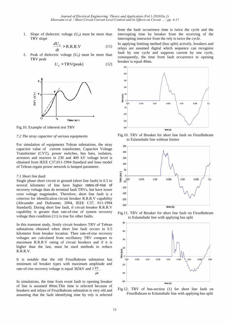
Fig.10. TRV of Breaker for short line fault on FiruzBahram to Eslamshahr line without limiter
-250
-200
-150
-100
-50
0
50
100
150
200
250
0.07 0.075 0.08 0.085 0.09 0.095 0.1
time (s)
TR
V (
kV)
Fig.11. TRV of Breaker for short line fault on FiruzBahram to Eslamshahr line with applying bus split
-60
-40
-20
0
20
40
60
80
0.02 0.025 0.03 0.035 0.04 0.045 0.05 0.055 0.06
time (s)
TRV
(kV
)
Fig.12. TRV of bus-section (1) for short line fault on FiruzBahram to Eslamshahr line with applying bus split
Journal of Electrical Engineering: Theory and Application (Vol.1-2010/Iss.1)Khorrami et al. / Short Circuit Current Level Control and its Effects on Circuit … / pp. 4-17
11
-150
-100
-50
0
50
100
150
0.02 0.025 0.03 0.035 0.04 0.045 0.05 0.055 0.06
time (s)
TR
V (
kV)
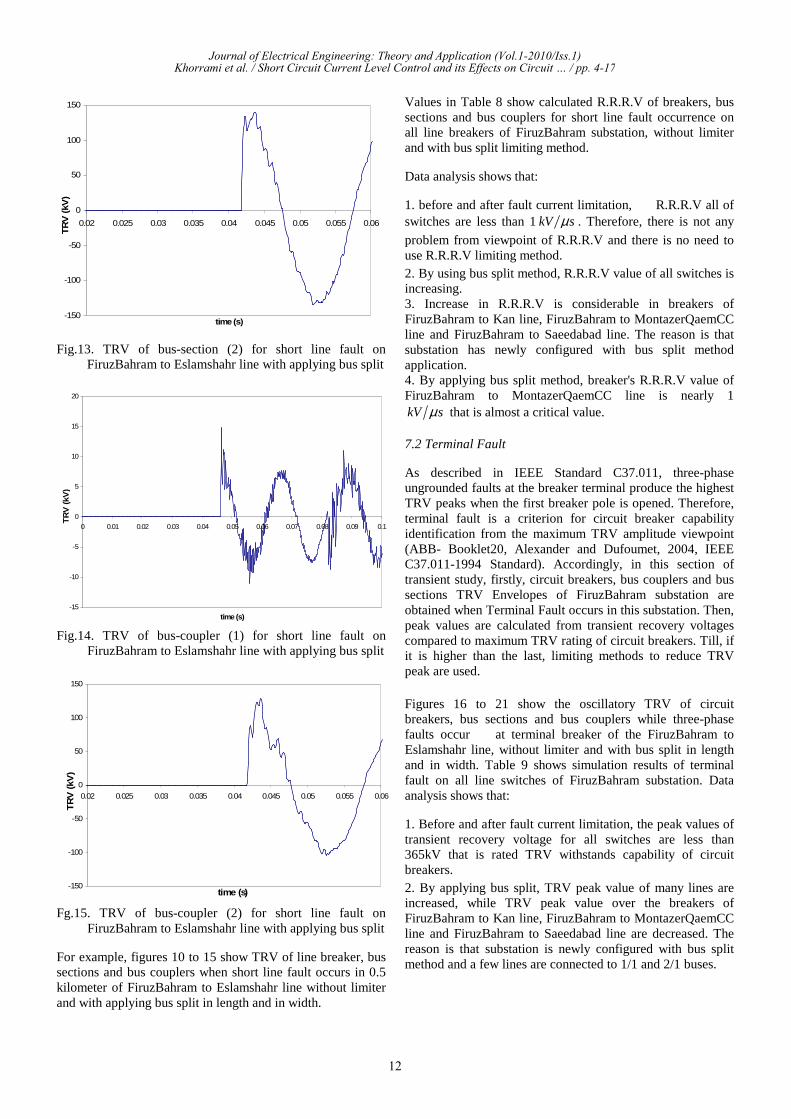
Fig.13. TRV of bus-section (2) for short line fault on FiruzBahram to Eslamshahr line with applying bus split
-15
-10
-5
0
5
10
15
20
0 0.01 0.02 0.03 0.04 0.05 0.06 0.07 0.08 0.09 0.1
time (s)
TR
V (
kV)
Fig.14. TRV of bus-coupler (1) for short line fault on FiruzBahram to Eslamshahr line with applying bus split
-150
-100
-50
0
50
100
150
0.02 0.025 0.03 0.035 0.04 0.045 0.05 0.055 0.06
time (s)
TR
V (
kV)
Fg.15. TRV of bus-coupler (2) for short line fault on FiruzBahram to Eslamshahr line with applying bus split
For example, figures 10 to 15 show TRV of line breaker, bus sections and bus couplers when short line fault occurs in 0.5 kilometer of FiruzBahram to Eslamshahr line without limiter and with applying bus split in length and in width.
Values in Table 8 show calculated R.R.R.V of breakers, bus sections and bus couplers for short line fault occurrence on all line breakers of FiruzBahram substation, without limiter and with bus split limiting method.
Data analysis shows that:
1. before and after fault current limitation, R.R.R.V all of switches are less than 1kV sµ . Therefore, there is not any
problem from viewpoint of R.R.R.V and there is no need to use R.R.R.V limiting method. 2. By using bus split method, R.R.R.V value of all switches is increasing. 3. Increase in R.R.R.V is considerable in breakers of FiruzBahram to Kan line, FiruzBahram to MontazerQaemCC line and FiruzBahram to Saeedabad line. The reason is that substation has newly configured with bus split method application. 4. By applying bus split method, breaker's R.R.R.V value of FiruzBahram to MontazerQaemCC line is nearly 1 kV sµ that is almost a critical value.
7.2 Terminal Fault
As described in IEEE Standard C37.011, three-phase ungrounded faults at the breaker terminal produce the highest TRV peaks when the first breaker pole is opened. Therefore, terminal fault is a criterion for circuit breaker capability identification from the maximum TRV amplitude viewpoint (ABB- Booklet20, Alexander and Dufoumet, 2004, IEEEC37.011-1994 Standard). Accordingly, in this section of transient study, firstly, circuit breakers, bus couplers and bus sections TRV Envelopes of FiruzBahram substation are obtained when Terminal Fault occurs in this substation. Then, peak values are calculated from transient recovery voltages compared to maximum TRV rating of circuit breakers. Till, if it is higher than the last, limiting methods to reduce TRV peak are used.
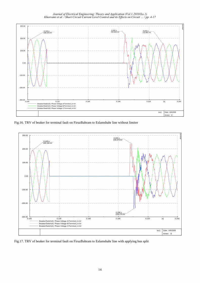
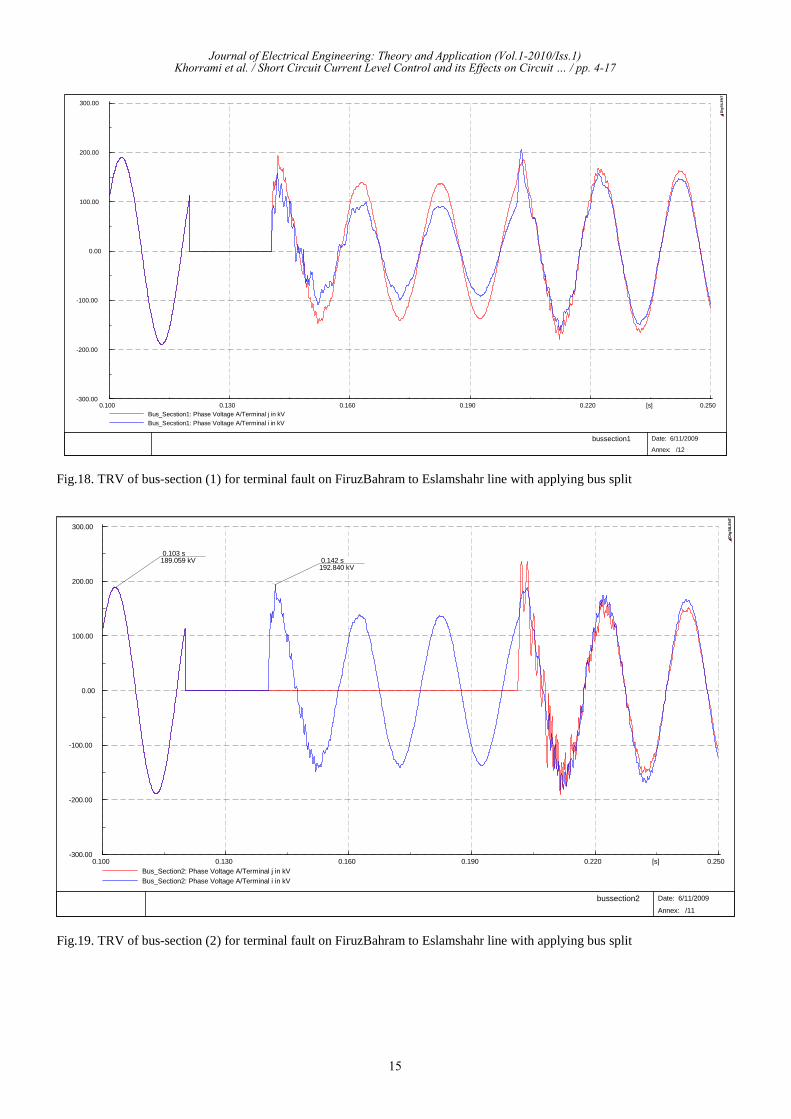
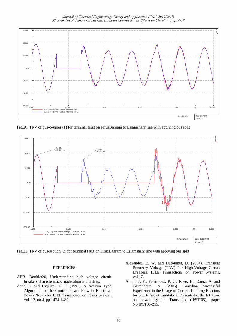
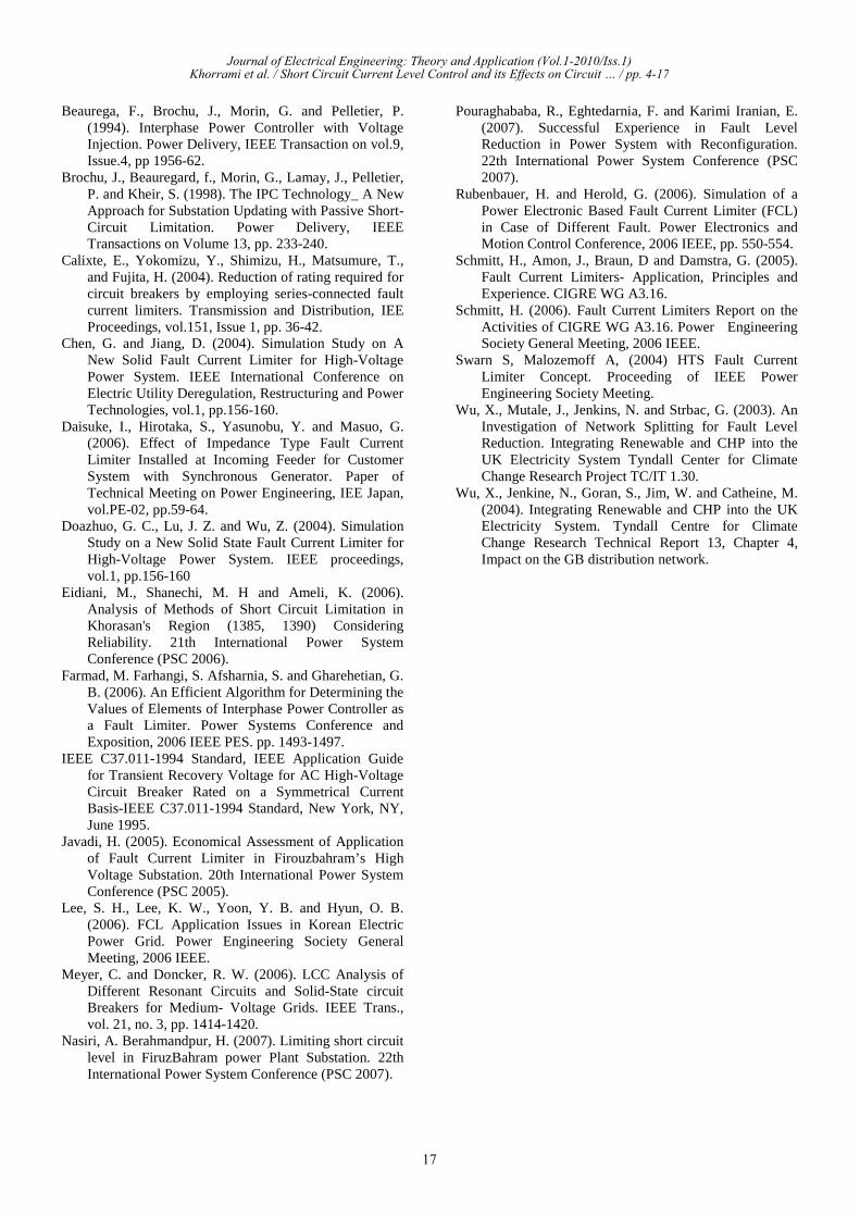
Figures 16 to 21 show the oscillatory TRV of circuit breakers, bus sections and bus couplers while three-phase faults occur at terminal breaker of the FiruzBahram to Eslamshahr line, without limiter and with bus split in length and in width. Table 9 shows simulation results of terminal fault on all line switches of FiruzBahram substation. Data analysis shows that:
1. Before and after fault current limitation, the peak values of transient recovery voltage for all switches are less than 365kV that is rated TRV withstands capability of circuit breakers. 2. By applying bus split, TRV peak value of many lines are increased, while TRV peak value over the breakers of FiruzBahram to Kan line, FiruzBahram to MontazerQaemCC line and FiruzBahram to Saeedabad line are decreased. The reason is that substation is newly configured with bus split method and a few lines are connected to 1/1 and 2/1 buses.
Journal of Electrical Engineering: Theory and Application (Vol.1-2010/Iss.1)Khorrami et al. / Short Circuit Current Level Control and its Effects on Circuit … / pp. 4-17
12
8. CONCLUSION
In this study, necessity of fault current limiter utilization in substations which face high short circuit current levels has been investigated. Then, considering infrastructure and condition of the substation, number of practically applicable methods are employed to control and reduce short circuit level and a suitable method is selected on the base of maximum reduction rate of fault current range after limiting as well as minimum variation rate of bus voltage and active power losses and static stability limit in Tehran Regional Electric Power Network. According to short circuit current level calculations in 400kV and 230kV Tehran regional electric power network by employing DigSilent software package, FiruzBahram substation in this area has fault current more than CB rated interrupting level and employing fault current limiters are necessary in this substation. Therefore,
fault current reduction methods such as bus split, series reactor, and low loaded line exit which has a considerable impression in fault current level reduction and also IPC were investigated. Among the over mentioned limiting methods, suitable suggested method considering dominant index for static study is bus split method in length and width actively. Simulations showed that fault current limiting methods change transient impedance of system and increase probability of rise transient recovery voltage amplitude and peak more than rated value of breakers which leads to breaker failure. Transient studies were conducted to investigate this problem and results revealed that bus split method in FiruzBahram substation do not cause that TRV peak and R.R.R.V of breakers exceed their standard value and does not have bad effects on Circuit Breakers' transient behavior.
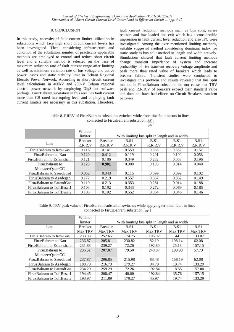
table 8. RRRV of FiruzBahram substation switches while short line fault occurs in lines connected to FiruzBahram substation
][S
kV
µ
With limiting bus split in length and in widthWithoutlimiter
B.S1R.R.R.V
B.S1R.R.R.V
B.S1R.R.R.V
B.S1R.R.R.V
BreakerR.R.R.V
BreakerR.R.R.VLine
0.1510.3520.3660.5590.1410.116FiruzBahram to Rey-Gas0.0580.1000.2010.1190.4120.120FiruzBahram to Kan0.1960.0680.2820.3490.1860.121FiruzBahram to Eslamshahr0.0400.0140.1050.3000.9010.123FiruzBahram to
MontazerQaemCC0.1020.0990.0990.1150.3430.052FiruzBahram to Saeedabad0.1490.3520.3670.5570.2190.177FiruzBahram to Azadegan0.1880.0140.2810.3530.2130.119FiruzBahram to ParandGas0.1850.0690.2720.3430.1920.103FiruzBahram to ToffBesat10.1460.3460.3640.5520.1920.103FiruzBahram to ToffBesat2
Table 9. TRV peak value of FiruzBahram substation switches while applying terminal fault in linesconnected to FiruzBahram substation [kV ]
With limiting bus split in length and in width Without limiter
B.S1 Max TRV
B.S1 Max TRV
B.S1 Max TRV
B.S1 Max TRV
Breaker Max TRV
Breaker Max TRV
Line
133.07 44 106.02 174.75 252.65 233.38 FiruzBahram to Rey-Gas 62.08 198.14 82.19 230.82 205.81 236.87 FiruzBahram to Kan 157.15 25.13 192.80 72.26 239.27 231.83 FiruzBahram to Eslamshahr 57.73 193.98 240.07 79.50 207.87 236.51 FiruzBahram to
MontazerQaemCC 62.08 158.19 83.48 215.98 206.85 237.87 FiruzBahram to Saeedabad 133.29 19.74 94.78 179.27 216.73 188.70 FiruzBahram to Azadegan 157.00 18.55 192.84 72.26 259.29 234.20 FiruzBahram to ParandGas 157.15 35.76 192.84 40.00 208.47 194.45 FiruzBahram to ToffBesat1 133.29 19.74 45.97 179.27 211.89 193.97 FiruzBahram to ToffBesat2
Journal of Electrical Engineering: Theory and Application (Vol.1-2010/Iss.1)Khorrami et al. / Short Circuit Current Level Control and its Effects on Circuit … / pp. 4-17
13
0.2600.2280.1960.1640.1320.100 [s]
300.00
200.00
100.00
0.00
-100.00
-200.00
-300.00
Breaker/Switch(4): Phase Voltage A/Terminal j in kVBreaker/Switch(4): Phase Voltage B/Terminal j in kVBreaker/Switch(4): Phase Voltage C/Terminal j in kV
0.202 s231.831 kV
0.242 s153.861 kV
0.103 s189.370 kV
trv1
Date: 6/9/2009
Annex: /2
DIg
SIL
EN
T
Fig.16. TRV of beaker for terminal fault on FiruzBahram to Eslamshahr line without limiter
0.2500.2200.1900.1600.1300.100 [s]
300.00
200.00
100.00
0.00
-100.00
-200.00
-300.00
Breaker/Switch(4): Phase Voltage A/Terminal j in kVBreaker/Switch(4): Phase Voltage B/Terminal j in kVBreaker/Switch(4): Phase Voltage C/Terminal j in kV
0.206 s-239.276 kV
0.203 s236.879 kV
0.103 s189.184 kV
trv1
Date: 6/9/2009
Annex: /2
DIg
SIL
EN
T
Fig.17. TRV of beaker for terminal fault on FiruzBahram to Eslamshahr line with applying bus split
Journal of Electrical Engineering: Theory and Application (Vol.1-2010/Iss.1)Khorrami et al. / Short Circuit Current Level Control and its Effects on Circuit … / pp. 4-17
14
0.2500.2200.1900.1600.1300.100 [s]
300.00
200.00
100.00
0.00
-100.00
-200.00
-300.00
Bus_Secstion1: Phase Voltage A/Terminal j in kVBus_Secstion1: Phase Voltage A/Terminal i in kV
bussection1
Date: 6/11/2009
Annex: /12
DIg
SIL
EN
T
Fig.18. TRV of bus-section (1) for terminal fault on FiruzBahram to Eslamshahr line with applying bus split
0.2500.2200.1900.1600.1300.100 [s]
300.00
200.00
100.00
0.00
-100.00
-200.00
-300.00
Bus_Section2: Phase Voltage A/Terminal j in kVBus_Section2: Phase Voltage A/Terminal i in kV
0.142 s192.840 kV
0.103 s189.059 kV
bussection2
Date: 6/11/2009
Annex: /11
DIg
SIL
EN
T
Fig.19. TRV of bus-section (2) for terminal fault on FiruzBahram to Eslamshahr line with applying bus split
Journal of Electrical Engineering: Theory and Application (Vol.1-2010/Iss.1)Khorrami et al. / Short Circuit Current Level Control and its Effects on Circuit … / pp. 4-17
15
0.2500.2200.1900.1600.1300.100 [s]
300.00
200.00
100.00
0.00
-100.00
-200.00
-300.00
Bus_Coupler1: Phase Voltage A/Terminal j in kVBus_Coupler1: Phase Voltage A/Terminal i in kV
buscoupler1
Date: 6/10/2009
Annex: /7
DIg
SIL
EN
T
Fig.20. TRV of bus-coupler (1) for terminal fault on FiruzBahram to Eslamshahr line with applying bus split
0.2500.2200.1900.1600.1300.100 [s]
300.00
200.00
100.00
0.00
-100.00
-200.00
-300.00
Bus_Coupler2: Phase Voltage A/Terminal i in kVBus_Coupler2: Phase Voltage A/Terminal j in kV
0.103 s189.184 kV 0.142 s
157.159 kV
buscoupler2
Date: 6/10/2009
Annex: /8
DIg
SIL
EN
T
Fig.21. TRV of bus-section (2) for terminal fault on FiruzBahram to Eslamshahr line with applying bus split
REFRENCES
ABB- Booklet20, Understanding high voltage circuit breakers characteristics, application and testing.
Acha, E. and Esquivel, C. F. (1997). A Newton Type Algorithm for the Control Power Flow in Electrical Power Networks. IEEE Transaction on Power System, vol. 12, no.4, pp.1474-1480.
Alexander, R. W. and Dufoumet, D. (2004). TransientRecovery Voltage (TRV) For High-Voltage Circuit Breakers. IEEE Transactions on Power Systems, vol.17.
Amon, J, F., Fernandez, P. C., Rose, H., Dajuz, A. and Castanheira, A. (2005). Brazilian Successful Experience in the Usage of Current Limiting Reactors for Short-Circuit Limitation. Presented at the Int. Con. on power system Transients (IPST’05), paper No.IPST05-215.
Journal of Electrical Engineering: Theory and Application (Vol.1-2010/Iss.1)Khorrami et al. / Short Circuit Current Level Control and its Effects on Circuit … / pp. 4-17
16
Beaurega, F., Brochu, J., Morin, G. and Pelletier, P. (1994). Interphase Power Controller with Voltage Injection. Power Delivery, IEEE Transaction on vol.9, Issue.4, pp 1956-62.
Brochu, J., Beauregard, f., Morin, G., Lamay, J., Pelletier, P. and Kheir, S. (1998). The IPC Technology_ A New Approach for Substation Updating with Passive Short-Circuit Limitation. Power Delivery, IEEE Transactions on Volume 13, pp. 233-240.
Calixte, E., Yokomizu, Y., Shimizu, H., Matsumure, T., and Fujita, H. (2004). Reduction of rating required for circuit breakers by employing series-connected fault current limiters. Transmission and Distribution, IEE Proceedings, vol.151, Issue 1, pp. 36-42.
Chen, G. and Jiang, D. (2004). Simulation Study on A New Solid Fault Current Limiter for High-Voltage Power System. IEEE International Conference on Electric Utility Deregulation, Restructuring and Power Technologies, vol.1, pp.156-160.
Daisuke, I., Hirotaka, S., Yasunobu, Y. and Masuo, G. (2006). Effect of Impedance Type Fault Current Limiter Installed at Incoming Feeder for Customer System with Synchronous Generator. Paper of Technical Meeting on Power Engineering, IEE Japan, vol.PE-02, pp.59-64.
Doazhuo, G. C., Lu, J. Z. and Wu, Z. (2004). Simulation Study on a New Solid State Fault Current Limiter for High-Voltage Power System. IEEE proceedings, vol.1, pp.156-160
Eidiani, M., Shanechi, M. H and Ameli, K. (2006). Analysis of Methods of Short Circuit Limitation in Khorasan's Region (1385, 1390) Considering Reliability. 21th International Power System Conference (PSC 2006).
Farmad, M. Farhangi, S. Afsharnia, S. and Gharehetian, G. B. (2006). An Efficient Algorithm for Determining the Values of Elements of Interphase Power Controller as a Fault Limiter. Power Systems Conference and Exposition, 2006 IEEE PES. pp. 1493-1497.
IEEE C37.011-1994 Standard, IEEE Application Guide for Transient Recovery Voltage for AC High-Voltage Circuit Breaker Rated on a Symmetrical Current Basis-IEEE C37.011-1994 Standard, New York, NY, June 1995.
Javadi, H. (2005). Economical Assessment of Application of Fault Current Limiter in Firouzbahram’s High Voltage Substation. 20th International Power SystemConference (PSC 2005).
Lee, S. H., Lee, K. W., Yoon, Y. B. and Hyun, O. B.(2006). FCL Application Issues in Korean Electric Power Grid. Power Engineering Society General Meeting, 2006 IEEE.
Meyer, C. and Doncker, R. W. (2006). LCC Analysis of Different Resonant Circuits and Solid-State circuitBreakers for Medium- Voltage Grids. IEEE Trans., vol. 21, no. 3, pp. 1414-1420.
Nasiri, A. Berahmandpur, H. (2007). Limiting short circuit level in FiruzBahram power Plant Substation. 22th International Power System Conference (PSC 2007).
Pouraghababa, R., Eghtedarnia, F. and Karimi Iranian, E. (2007). Successful Experience in Fault Level Reduction in Power System with Reconfiguration. 22th International Power System Conference (PSC 2007).
Rubenbauer, H. and Herold, G. (2006). Simulation of a Power Electronic Based Fault Current Limiter (FCL) in Case of Different Fault. Power Electronics and Motion Control Conference, 2006 IEEE, pp. 550-554.
Schmitt, H., Amon, J., Braun, D and Damstra, G. (2005). Fault Current Limiters- Application, Principles andExperience. CIGRE WG A3.16.
Schmitt, H. (2006). Fault Current Limiters Report on the Activities of CIGRE WG A3.16. Power Engineering Society General Meeting, 2006 IEEE.
Swarn S, Malozemoff A, (2004) HTS Fault Current Limiter Concept. Proceeding of IEEE Power Engineering Society Meeting.
Wu, X., Mutale, J., Jenkins, N. and Strbac, G. (2003). An Investigation of Network Splitting for Fault Level Reduction. Integrating Renewable and CHP into the UK Electricity System Tyndall Center for Climate Change Research Project TC/IT 1.30.
Wu, X., Jenkine, N., Goran, S., Jim, W. and Catheine, M. (2004). Integrating Renewable and CHP into the UK Electricity System. Tyndall Centre for Climate Change Research Technical Report 13, Chapter 4, Impact on the GB distribution network.
Journal of Electrical Engineering: Theory and Application (Vol.1-2010/Iss.1)Khorrami et al. / Short Circuit Current Level Control and its Effects on Circuit … / pp. 4-17
17