Shock Generation and Control Using DBD Plasma Actuators · PDF fileMehul P. Patel, Alan B....
40
Mehul P. Patel, Alan B. Cain, and Christopher C. Nelson Innovative Technology Applications Company (ITAC), LLC, Chesterfield, Missouri Thomas C. Corke and Eric H. Matlis University of Notre Dame, Notre Dame, Indiana Shock Generation and Control Using DBD Plasma Actuators SBIR Phase I Final Report NASA/CR—2012-217448 June 2012 https://ntrs.nasa.gov/search.jsp?R=20120011134 2018-04-29T13:18:35+00:00Z
Transcript of Shock Generation and Control Using DBD Plasma Actuators · PDF fileMehul P. Patel, Alan B....
Mehul P. Patel, Alan B. Cain, and Christopher C. NelsonInnovative Technology Applications Company (ITAC), LLC, Chesterfi eld, Missouri
Thomas C. Corke and Eric H. MatlisUniversity of Notre Dame, Notre Dame, Indiana
Shock Generation and Control Using DBDPlasma ActuatorsSBIR Phase I Final Report
NASA/CR—2012-217448
June 2012
https://ntrs.nasa.gov/search.jsp?R=20120011134 2018-04-29T13:18:35+00:00Z

NASA STI Program . . . in Profi le
Since its founding, NASA has been dedicated to the advancement of aeronautics and space science. The NASA Scientifi c and Technical Information (STI) program plays a key part in helping NASA maintain this important role.
The NASA STI Program operates under the auspices of the Agency Chief Information Offi cer. It collects, organizes, provides for archiving, and disseminates NASA’s STI. The NASA STI program provides access to the NASA Aeronautics and Space Database and its public interface, the NASA Technical Reports Server, thus providing one of the largest collections of aeronautical and space science STI in the world. Results are published in both non-NASA channels and by NASA in the NASA STI Report Series, which includes the following report types: • TECHNICAL PUBLICATION. Reports of
completed research or a major signifi cant phase of research that present the results of NASA programs and include extensive data or theoretical analysis. Includes compilations of signifi cant scientifi c and technical data and information deemed to be of continuing reference value. NASA counterpart of peer-reviewed formal professional papers but has less stringent limitations on manuscript length and extent of graphic presentations.
• TECHNICAL MEMORANDUM. Scientifi c
and technical fi ndings that are preliminary or of specialized interest, e.g., quick release reports, working papers, and bibliographies that contain minimal annotation. Does not contain extensive analysis.
• CONTRACTOR REPORT. Scientifi c and
technical fi ndings by NASA-sponsored contractors and grantees.
• CONFERENCE PUBLICATION. Collected papers from scientifi c and technical conferences, symposia, seminars, or other meetings sponsored or cosponsored by NASA.
• SPECIAL PUBLICATION. Scientifi c,
technical, or historical information from NASA programs, projects, and missions, often concerned with subjects having substantial public interest.
• TECHNICAL TRANSLATION. English-
language translations of foreign scientifi c and technical material pertinent to NASA’s mission.
Specialized services also include creating custom thesauri, building customized databases, organizing and publishing research results.
For more information about the NASA STI program, see the following:
• Access the NASA STI program home page at http://www.sti.nasa.gov
• E-mail your question via the Internet to help@
sti.nasa.gov • Fax your question to the NASA STI Help Desk
at 443–757–5803 • Telephone the NASA STI Help Desk at 443–757–5802 • Write to:
NASA Center for AeroSpace Information (CASI) 7115 Standard Drive Hanover, MD 21076–1320

Mehul P. Patel, Alan B. Cain, and Christopher C. NelsonInnovative Technology Applications Company (ITAC), LLC, Chesterfi eld, Missouri
Thomas C. Corke and Eric H. MatlisUniversity of Notre Dame, Notre Dame, Indiana
Shock Generation and Control Using DBDPlasma ActuatorsSBIR Phase I Final Report
NASA/CR—2012-217448
June 2012
National Aeronautics andSpace Administration
Glenn Research CenterCleveland, Ohio 44135
Prepared under Contract NNX11CD87P

Available from
NASA Center for Aerospace Information7115 Standard DriveHanover, MD 21076–1320
National Technical Information Service5301 Shawnee Road
Alexandria, VA 22312
Available electronically at http://www.sti.nasa.gov
Trade names and trademarks are used in this report for identifi cation only. Their usage does not constitute an offi cial endorsement, either expressed or implied, by the National Aeronautics and
Space Administration.
This work was sponsored by the Fundamental Aeronautics Program at the NASA Glenn Research Center.
Level of Review: This material has been technically reviewed by NASA technical management.
Acknowledgments
This research was supported under a NASA Small Business Innovation Research (SBIR) Phase I Contract (#NNX11CD87P). The period of performance for this research effort was February 17 to September 27, 2011. Dr. David E. Ashpis was the Technical Offi cer. The authors thank Dr. David Ashpis from the Turbomachinery and Heat Transfer Branch at the NASA Glenn Research Center (GRC), and Dr. David Davis, Ms. Mary Jo Long-Davis, and Ms. Stephanie Hirt from the Inlet and Nozzle Branch (NASA GRC), for their helpful comments and support for this work. We also thank Dr. Nick Georgiadis and Ms. Stephanie Hirt of NASA GRC for providing the computational grid for the inlet geometry (case c) for this work.

NASA/CR—2012-217448 1
Shock Generation and Control Using DBD Plasma Actuators SBIR Phase I Final Report
Mehul P. Patel, Alan B. Cain, and Christopher C. Nelson
Innovative Technology Applications Company (ITAC), LLC Chesterfield, Missouri 63006
Thomas C. Corke and Eric H. Matlis
University of Notre Dame Notre Dame, Indiana 46556
Project Summary
Shock-wave boundary-layer interactions (SBLI) are key limiting phenomena in high-speed flight as they are ubiquitous in a number of external and internal flow problems. The phenomena adversely impacts both aerodynamic and propulsion performance of the vehicle including, control authority, component fatigue life, and structural integrity. These effects, however, can be corrected using appropriate methods of flow control. The SBLI phenomena in a supersonic inlet involve mutual interaction of oblique shocks with boundary layers, forcing the boundary layer to separate from the inlet wall. To improve the inlet efficiency, it is desired to prevent or delay shock-induced boundary layer separation. In this effort, Innovative Technology Applications Company (ITAC), LLC and the University of Notre Dame (UND) jointly investigated the use of dielectric-barrier-discharge (DBD) plasma actuators for control of SBLI in a supersonic inlet.
The research investigated the potential for DBD plasma actuators to suppress flow separation caused by a shock in a turbulent boundary layer. The research involved both numerical and experimental investigations of plasma flow control for a few different SBLI configurations: (a) a 12° wedge flow test case at Mach 1.5 (numerical and experimental), (b) an impinging shock test case at Mach 1.5 using an airfoil as a shock generator (numerical and experimental), and (c) a Mach 2.0 nozzle flow case in a simulated 1515 cm wind tunnel with a shock generator (numerical). Numerical studies were performed for all three test cases to examine the feasibility of plasma flow control concepts. These results were used to guide the wind tunnel experiments conducted on the Mach 1.5 12° wedge flow (case a) and the Mach 1.5 impinging shock test case (case b) which were at similar flow conditions as the corresponding numerical studies to obtain experimental evidence of plasma control effects for SBLI control. The experiments also generated data that were used in validating the numerical studies for the baseline cases (without plasma actuators). The experiments were conducted in a Mach 1.5 test section in the University of Notre Dame Hessert Laboratory.
The simulation results from cases a and b indicated that multiple spanwise actuators in series and at a voltage of 75 kVp-p could fully suppress the flow separation downstream of the shock. The simulation results from case c showed that the streamwise plasma actuators are highly effective in creating pairs of counter-rotating vortices, much like the mechanical vortex generators, and could also potentially have beneficial effects for SBLI control. However, to achieve these effects, the positioning and the quantity of the DBD actuators used must be optimized. It should be noted that all simulation results do not incorporate pressure effects in the plasma model.
The experimental results were limited by the inability to generate a sufficiently high voltage due to arcing in the wind-tunnel test-section. Simulations indicated that a minimum of 75 kVp-p was required to obtain suppression of the separation bubble at atmospheric static pressures. However, at voltages greater than 60 kVp-p arcs were formed to the tunnel side-walls which prevented any further increase in voltage. This resulted in a generated body force which was significantly less than the amount used in the simulations. Since the plasma body force scales as the applied voltage to the 3.5 power, the achieved body force was at best less than half of what was required. This limitation was further compounded by the low (1 bar)
NASA/CR—2012-217448 2
stagnation pressure condition of the in-draft tunnel. This resulted in low static pressures at the design Mach number that potentially reduced the plasma effectiveness and also exacerbated the observed arcs.
The plasma actuators used in the experiments made use of the developed design guidelines for low static pressure operation. These included having a low capacitance per area in order to increase the voltage needed to ionize the air, thus maximizing body force. This was achieved by using a thick dielectric material. While these measures helped to extend the voltage range of the actuators, they were insufficient to overcome the basic limitations of the facility. It should be noted that much of these challenges are not consistent with the intended application. The low static pressures in the experiments are not representative of the supersonic inlet application which is the focus of the study.
Despite the inability to match voltages between simulation and experiment, considerable effort was made to replicate the simulated flow control conditions using the spanwise plasma actuators (for cases a and b) in the wind tunnel experiments. To this end, the experimental flow field was documented using Schlieren flow visualization, wall static pressure measurements, Preston tube measurements, and surface shear-stress flow visualization. These measurements confirmed the essential similarity between the simulated and experimental baseline conditions (without plasma actuators). In particular, static pressure measurements confirmed the pressure distribution over the wedge while Preston measurements were used to identify the location of the separation front which compared favorably to the simulations. The Schlieren images also agreed perfectly with simulations.
1.0 Introduction
The proposed innovations are as follows:
1. Design and development of DBD plasma actuators for control of SBLI in a supersonic inlet 2. New and improved designs of DBD plasma actuators suitable for high-speed flow control
applications 3. Selection of dielectric materials that lower the capacitance of the plasma actuators that improved the
body force by an order of magnitude over earlier designs
The significance of the innovation are:
1. provides a capability to actively control or delay the onset of flow separation in supersonic inlets without the need for boundary layer bleed or mechanical devices
2. reduces system complexity and costs in the application of a flow control device for SBLI control due to its simple, light-weight design with no moving parts, which can be applied directly onto the surface
3. reduces power requirements for achieving flow control, and 4. improves vehicle performance in transient flow conditions through active control of DBD plasma
actuator control parameters for optimal operation at all times
The proposed innovations of the DBD plasma actuator technology have the potential to significantly reduce system complexity and power requirements of an active flow control system for use in supersonic inlets. The DBD plasma actuators are sufficiently simple in design, in that they can be flush mounted with little to no intrinsic drag, and can be turned off when not required. This makes it possible to develop a system of actuators that have wide applicability with few design penalties applied over large surface areas, which can also be dynamically re-configured in real time to focus the flow-control at the point of maximum sensitivity depending on the present flow conditions. Additionally, the DBD plasma actuators are fully electronic, low power devices with high bandwidth capabilities. With no moving parts or need for plumbing whatsoever, the DBD plasma actuators make an attractive choice for use in future propulsion systems. Finally, the use of high-temperature alloys and ceramics in their design would allow operation in realistic engine environments.

NASA/CR—2012-217448 3
1.1 Background
The Supersonics Project under NASA’s Aeronautics Research Mission Directorate seeks technologies that improve performance and efficiencies of propulsion and aerodynamic subsystems in air vehicles. Shock-wave boundary-layer interactions are key limiting phenomena in high-speed flight as they are ubiquitous in a number of external and internal flow problems. The phenomena adversely impacts both aerodynamic and propulsion performance of the vehicle including, control authority, component fatigue life, and structural integrity. These effects, however, can be corrected using appropriate methods of flow control.
Flow control technology is viewed by many as a key component in the design of future vehicles. Improving vehicle aerodynamics requires the control and manipulation of flowfield on aerodynamic surfaces. This fundamental need has led to the development of many different flow control actuators and control techniques over the years (Ref. 1). Examples of flow control can be separated into two classes: passive and active. Examples include traditional and micro vortex generators (Refs. 2 to 4), suction (Ref. 5), blowing (Ref. 6), oscillatory blowing/suction (Ref. 7), synthetic jet actuators (Ref. 8), and plasma actuators (Refs. 9 and 10).
Several types of flow control devices have been investigated for SBLI control. These include, but are not limited to, suction, blowing, mechanical vortex generators (VGs) (including micro-devices such as micro-vanes, tapered micro-vanes and micro-ramps), and plasma actuators. Suction is not cost-effective to implement and requires considerable amount of flow to be removed which results in reduced inlet efficiency. Micro-VGs have been shown to delay shock-induced separations with significantly reduced device drag when compared to traditional VGs. However, the presence of a mechanical device in internal flows can still cause considerable damage to the system when it fails, hence, to improve the structural rigidity, there is a need to develop a flow control solution that is easy to integrate and is less intrusive in high-speed inlet flows. The limitations of the current mechanical and fluidic approaches to flow control for the SBLI problem provide motivation for a fully electronic system based on the use of a DBD plasma actuator.
1.2 DBD Plasma Actuators
DBD plasma actuators consist of two electrodes that are separated by a dielectric layer. One electrode is exposed to the air and the other is insulated. A general configuration of a DBD plasma actuator is shown in Figure 1. They have the electric properties of a capacitor and therefore are powered by an AC voltage. When the AC amplitude is large enough, the air ionizes in the region of the largest electric potential. The ionized air is referred to as a plasma. This generally begins at the edge of the electrode that is exposed to the air, and spreads out over the area projected by the covered electrode.
The flow control mechanism in the DBD plasma actuator is through a generated body-force vector field that energizes the boundary layer via momentum mixing. These actuators have demonstrated promising applications in a wide range of internal and external flow-control problems. Although initially considered to be useful only at low-speeds, they have recently been shown to be effective in a number of applications at high subsonic, transonic, and supersonic Mach numbers (Ref. 10). This has largely come from improved and optimized actuator designs developed through better understanding and modeling of the actuator physics.
The method of flow control with the DBD plasma actuators is through the generated body force vector field. An extensive effort has been made to develop computationally efficient models for the plasma actuators. This includes work by Orlov (Refs. 11 and 12), Mertz (Ref. 13), and Mertz and Corke (Ref. 14). These models have been fully validated with experiments. These studies are essential to predict the response of the flow due to the presence of the plasma actuators, as well as in optimizing their performance. For example they showed the benefit of the selection of dielectric materials that lower the capacitance of the plasma actuators that improved the body force by an order of magnitude over earlier designs (Ref. 15). An example of the body force vector field during one time instant in the AC cycle from

NASA/CR—2012-217448 4
simulations by Mertz and Corke (Ref. 14), is shown in the right part of Figure 1. This illustrates that the largest body force vectors are oriented from the exposed electrode (thick red horizontal line) towards the dielectric surface (thin red horizontal line). In addition, it illustrates the significant number of body force vectors that are oriented towards the surface of the dielectric. This is a feature that is unique to other flow control devices that makes it particularly effective at controlling flow separation. A detailed overview of the DBD plasma actuators is provided in Corke et al. (Ref. 16). For a discussion on the physics and underlying mechanisms of the aerodynamic plasma actuator, see articles by Enloe et al. (Refs. 17 and 18).
The attraction of this actuator as a flow control device lies in potential for a large payoff owing to its special features that include, being fully electronic with no moving parts, having a fast time response for unsteady applications, having a very low mass which is especially important in applications with high g-loads, being able to apply the actuators onto surfaces without the addition of cavities or holes, having an efficient conversion of the input power into fluid momentum, and the easy ability to simulate their effect in numerical flow solvers. The simplicity in its design makes it possible to apply over large surface areas with few design penalties, which can also be dynamically re-configured in real time to focus the flow-control at the point of maximum sensitivity depending on the present flow conditions.
In this project, we investigated the use of DBD plasma actuators for control of SBLI in a supersonic inlet. The SBLI phenomena in a supersonic inlet involve mutual interaction of oblique shocks with boundary layers, forcing the boundary layer to separate from the inlet wall. To improve the inlet efficiency, it is desired to prevent or delay shock-induced boundary layer separation. In this effort, we examined the efficacy of DBD plasma actuators over a generic flat plate model for control of shock-induced boundary layer separation using a combination of computational and wind tunnel experiments. Two different designs of DBD plasma actuators were studies. These designs are discussed below.
a) Spanwise plasma actuator In this configuration, the actuator consists of two asymmetrically overlapped metal
electrodes, separated by a dielectric material, as illustrated in Figure 1. The upper electrode is exposed to the surrounding air and the lower (covered) electrode is fully insulated. When a sufficiently high-amplitude ac voltage is supplied to the electrodes, the air over the covered electrode ionizes. The ionized air is referred to as the plasma. The basis of this actuator is that the plasma, in the presence of the electric field gradient produced by the electrode geometry, results in a body force vector that acts on the ambient air. The electrodes extend in the spanwise direction and the result of the imposed body force is the production of steady or unsteady near-wall plasma-induced blowing, which adds momentum to the near-wall region of the boundary layer. This is beneficial in terms of preventing flow separation.
Figure 1.—Schematic of a DBD plasma actuator (left) and computed body force vector field during an instant in the AC cycle from Mertz and Corke (Ref. 14).

NASA/CR—2012-217448 5
Figure 2.—Schematic of plasma streamwise vortex generators (left) and photograph of plasma vortex generators in operation (right).
b) Plasma streamwise vortex generator (PSVG)
The PSVG takes an alternate approach. Here, the exposed electrode is parallel with the mean flow direction. In a more recent design, as shown in the left part of Figure 2, the edges of the exposed electrodes are oriented at an angle with respect to the mean flow direction. The plasma is forced in the spaces between the neighbor exposed electrodes. This is shown in the right part of Figure 2 where the photograph captures the purple light emission of the plasma. The body force vectors, Fb, are outward-perpendicular to the edges of the exposed electrodes. This design produces streamwise oriented counter-rotating vortex pairs (of different strengths) that induce cross-stream momentum transport and thereby prevent flow separation. The effect is similar to that produced by passive vortex generators.
1.3 SBLI Control Approach
The proposed SBLI control approach is based upon early experimental findings reported by Thomas et al. (Ref. 19) at the University of Notre Dame, on the mechanism of unsteady shock oscillation in SBLI. The unsteady shock oscillation phenomenon was first noted in early qualitative studies by Bogdonoff (Ref. 20), Price and Stallings (Ref. 21), Kaufman et al. (Ref. 22), and Winkelmann (Ref. 23). Several investigations since then have suggested that shock oscillation is related to unsteady motions within the separation bubble at the foot of the shock (Refs. 24 to 28), and that the oscillation of the shock front is more severe when the flow exhibits separation. Based upon the literature cited, there can be little doubt that the separation region plays an important role in shock oscillation. The experiments conducted by Thomas et al. (Ref. 19) suggest a very strong global relationship between separation bubble motion and shock oscillation. This experimental work (Ref. 19) was conducted in an open-return supersonic wind tunnel located at the Hessert Laboratory at the University of Notre Dame (the same facility we used in the present effort).
Building on these research findings, we conducted new numerical simulations and wind tunnel experiments to develop a deeper understanding of the main mechanisms of SBLI, to guide us further in the development of effective steady and unsteady DBD plasma flow control concepts for effective control of SBLI. One of the main aspects of the present work was to obtain estimates on the influence of a DBD plasma actuator located just upstream of the shock on the downstream boundary layer and separation bubble. The following technical objectives were developed for this research effort.
2.0 Research Objectives
The overall objective of this research effort is to demonstrate the technical feasibility of the proposed DBD plasma actuators for control of shock wave/boundary layer interactions in a supersonic inlet.

NASA/CR—2012-217448 6
The specific objectives are:
Develop a flat plate floor model and necessary hardware for conducting SBLI control experiments using DBD plasma actuators
Investigate two configurations of DBD plasma actuators for SBLI control Conduct experiments to demonstrate delay of shock-induced separation Conduct CFD simulations of promising PSVG configurations for detailed flowfield analysis and
prediction of shock-induced flow separation control
3.0 Work Accomplished
The research focused on investigating two specific designs of DBD plasma actuators for control of shock-induced flow separation in a supersonic inlet. The first design featured a spanwise plasma actuator and the second design featured a novel configuration referred to as PSVG where the plasma devices are configured to mimic the effect of mechanical VGs. Both computational and experimental studies were conducted in this effort to gain insight into the effect of these DBD plasma actuators.
To achieve the technical objectives, the research included the following technical approach.
3.1 Technical Approach
The approach involved numerical investigations of plasma flow control for a few different SBLI configurations: (a) a 12° wedge flow test case at Mach 1.5, (b) an impinging shock test case at Mach 1.5 using an airfoil as a shock generator, and (c) a Mach 2.0 nozzle flow case in a simulated 1515 cm wind tunnel with a shock generator. The work largely involved independent numerical studies for all three test cases to examine the feasibility of plasma flow control concepts.
Additionally, limited wind tunnel experiments were also conducted on the Mach 1.5 12° wedge flow (case a) and the Mach 1.5 impinging shock test case (case b), at similar flow conditions as numerical studies, to obtain experimental evidence of plasma control effects for SBLI control. The experiments also generated data that were used in validating numerical studies for the baseline case (without plasma actuators). The experiments were conducted in a Mach 1.5 test section in the University of Notre Dame Hessert Laboratory.
3.1.1 Case a: Wedge Flow
The object of this study was to investigate the potential of DBD plasma flow control to suppress flow separation caused by a shock generated upstream of a 12° wedge placed on the boundary layer wall. Numerical simulations were conducted using Fluent to study the effect of spanwise DBD plasma actuators on SBLI in a Mach 1.5 flow over a flat plate model containing a 12° wedge at the conditions of the experiment. The study included a baseline flow case with no actuator and a case with two spanwise-oriented plasma actuators in series.
3.1.2 Case b: Impinging Shock
The object of this study was to investigate the potential of DBD plasma flow control to suppress flow separation caused by an impinging shock generated by a supersonic airfoil placed in the free-stream of the test section. The first series of impinging shock simulations were performed for conditions caused by a supersonic airfoil placed in the free-stream of the test section. The flow simulation was similar to that of the wedge flow. It again utilized the Fluent flow solver. The simulations investigated a case of two spanwise-oriented plasma actuators and a case of four spanwise-oriented plasma actuators for reducing flow separation caused by the impinging shock.

NASA/CR—2012-217448 7
3.1.3 Case c: Nozzle Flow
The object of this study was to investigate the potential of DBD plasma flow control to suppress flow separation caused by a shock generated using a shock generator plate in a 1515 cm tunnel configuration (at Mach 2), which was the object of study by researchers at NASA Glenn. A shock generator plate was mounted in the tunnel, exactly as in the NASA experiments and simulations. The work by NASA researchers examined mechanical vortex generators to control the shock-induced separation. In the present numerical (only) study, we focused on a relatively new and an innovative design of a DBD plasma actuator, referred to as a PSVG, in which the electrodes were oriented in streamwise direction, which have been shown to generate vortices similar to mechanical VGs for use in flow separation control. The study included a baseline flow case with no actuator, a case with two PSVGs, and a case with four PSVGs. Estimates of boundary layer separation control using PSVGs were obtained. This numerical study was conducted using Wind-US. As a matter of fact, Wind-US was solely used for case c simulations.
In summary, the research involved the following studies Case a: Wedge Flow
Numerical studies using Fluent, Mach 1.5 - Control-off: baseline - Two spanwise-oriented plasma actuators
Wind tunnel experiments, Mach 1.5 - Control-off: baseline (data used validating CFD baseline case) - Plasma flow control: two spanwise-oriented plasma actuators (inconclusive data
due to hardware problems) Case b: Impinging Shock
Numerical studies using Fluent, Mach 1.5 - Control-off: baseline (similar to the baseline case of wedge flow) - Two spanwise-oriented plasma actuators - Four spanwise-oriented plasma actuators
Wind tunnel experiments, Mach 1.5 - Control-off: baseline (data used validating CFD baseline case) - Plasma flow control: two spanwise-oriented plasma actuators (inconclusive data
due to hardware problems) Case c: Nozzle Flow
Numerical studies using Wind-US, Mach 2.0 - Control-off: baseline (similar to the baseline case from NASA study) - Two plasma streamwise vortex generators - Four plasma streamwise vortex generators
3.2 Task Descriptions
3.2.1 Task 1. Experiments and Simulations Over a Flat Plate With a 12° Surface Wedge at M = 1.5
The object of this research program was to investigate the potential of DBD plasma flow control to suppress flow separation caused by an impinging shock in a turbulent boundary layer. The experiments were conducted in a Mach 1.5 test section in the University of Notre Dame Hessert Laboratory, shown in Figure 3. The test section was previously used for SBLI studies by Thomas et al. (Ref. 19). A photograph of the Mach 1.5 wind tunnel, and a portion of the test section with the 12° wedge are shown in Figure 4. The test section dimensions are 5 in. (12.7 cm) wide by 3.8 in. (9.6 cm) high. The wedge model is a removable floor piece which is located at the end of a slightly expanding 4-ft duct designed to

NASA/CR—2012-217448 8
Figure 3.—Photograph of Mach 1.5 wind tunnel in the UND Hessert Laboratory (left) and portion of the
measurement section showing the 12 wedge with Preston tube and DBD plasma actuator.
Figure 4.—Photograph of the 12 wedge (left) and suspended supersonic airfoil (right) that were used to
produce shock-boundary layer interaction. accommodate the growth of the boundary layer while providing a slightly favorable pressure gradient. The test section was connected to a pair of vacuum pumps in the Hessert Lab. The air was pulled from the laboratory space so that the tunnel stagnation pressure was P₀ = 1 bar. The vacuum pumps were capable of maintaining the design Mach 1.5 indefinitely.
Two flow configurations and two DBD plasma actuator designs were investigated. The flow configurations consisted of a 12° wedge placed on the boundary layer wall, and a supersonic airfoil that served as a shock generator, which was suspended with an inclination of 6.5 in the free-stream above the wall. The wedge model was similar to that used by Thomas et al. (Ref. 19). The supersonic airfoil had a sharp leading edge and a blunt trailing edge. It was held in slots in the Plexiglass side walls at an angle of attack so that the upper surface at the leading edge was parallel to the roof of test section.
3.2.2 Wedge Flow
Simulations were conducted using the commercial flow solver Fluent V12.0.1, with a grid generated using Gambit. Gambit has since been discontinued by the parent company ANSYS and is no longer available for use. The domain for these calculations can be seen in Figure 5. The dimensions of the domain are provided in both physical units as well as the number of quadrilateral grid elements. Boundary conditions are also given. Calculations were made using the steady two-dimensional, compressible flow solver that incorporated the shear-stress transport k-ω turbulence model to predict the boundary layer growth. A density-based implicit formulation was used with a second-order Roe flux-difference splitting scheme for the convective terms. A low time step CFL of 0.1 was used. Iterations were allowed to proceed until convergence was achieved as monitored by flow residuals. The inflow was allowed to
Flow
CeilingJunction
FloorJunction
UpperElectrode
12‐degWedge
Pitot Probe
Preston Tube
Glass Side‐wallCovered
Electrode
Flow
Flow
6.5‐deg Shock Generator
Plasma Actuator
Preston Tube

NASA/CR—2012-217448 9
Figure 5.—Computational domain used for the simulations over a flat plate with a 12 surface wedge.
develop over a length of approximately 1.4 m to ensure a realistic boundary layer height approaching the wedge model. Far-field boundary conditions were used to prescribe the Mach number upstream of the wedge, while an outflow pressure boundary condition was used at the exit.
The 12° wedge model was examined at the conditions of the experiment. These were an inflow Mach number of 1.5, and T₀ = 290 K and P₀ = 98.6 kPa. The case without the plasma actuator body force added to the simulation represented the baseline condition. This was used to identify key parameters such as the thickness of the boundary-layer at the location of the wedge, the location of the upstream shock, and the locations of flow separation and re-attachment downstream of the shock.
The second flow simulation included the body force from a separate DBD plasma actuator simulation developed by Mertz and Corke (Ref. 14). This body force model does not incorporate any pressure dependence. The flow simulation included the effect of two spanwise oriented actuators in series. The body force was steady with an AC frequency of 2 kHz and equivalent to an input voltage of 75 kVp-p. The plasma actuators were located so that the upstream actuator (defined by the downstream edge of the exposed electrode) was at the flow separation location, and the second actuator was located 1 cm downstream of the first. The actuators were oriented so that the body forces were each in the mean flow direction.
The results of the two simulations are presented in Figure 6. This is shown as contours of constant Mach number. The boundary-layer develops to a height of approximately 0.55 in. (14 mm) at the point of separation. Flow separation occurs just downstream of the shock at a position that is 1.13 in. (28.9 mm) upstream of the base of the wedge. The flow re-attachment occurs on the wedge.
Validation of the baseline flow simulations was performed by comparing the streamwise pressure gradient and skin friction in the boundary layer near the wedge measured from the wind tunnel experiments. This is shown in Figure 7. The left plot in the figure shows the pressure gradient near the wedge. The results from the simulation correspond to the star-symbols. The experimental results are shown by the x-symbols. The location x = 0 corresponds to the base of the wedge. The agreement between the simulation and the experiment is excellent close to the wedge. The deviation in the experimental pressure ratio around x = –2 in. has been traced to a weak shock that originates in a joint in the ceiling of the test section. This is illustrated in the overlay of the pressure measurements onto the Schlieren image in Figure 8.
The overlay of the pressure distribution onto the Schlieren flow visualization in Figure 8 illustrates that the large pressure rise near the base of the wedge coincides with the oblique shock. The pressure gradient produced by the shock results in a flow separation. This is revealed in the skin friction measurements.
Flow

NASA/CR—2012-217448 10
Figure 6.—Simulations of the flow over a 12 wedge without DBD plasma actuator (left) with two series
DBD plasma actuators at 75 kV (right).
Figure 7.—Comparison between baseline flow simulation and experiment for the flow over a 12
wedge at Mach 1.5.
Figure 8.—Measured pressure gradient overlayed onto Schlieren flow image
that correlates pressure deviation between simulation and experiment with unintended shock emanating from test section ceiling.
Wall skin friction from the simulation and the experiment are compared in the right part of Figure 7.
Again x = 0 corresponds to the base of the wedge. In this plot, the flow simulation result is shown by the plus-symbols. The x-location where the skin friction is negative indicates the region where the flow is separated. The star-symbols correspond to the experimental results based on an un-calibrated Preston tube. The Preston tube extended through the center of the wedge on the floor. Its main purpose was to indicate where the skin friction was near zero. It was not capable of measuring negative skin friction associated with a flow recirculation region. The location where the Preston tube measurement is zero very closely corresponds to the zero crossing location of the skin friction obtained from the simulation. Therefore the location and extent of the flow separation caused by the shock is closely validated.
X(in)1‐1‐2
X(m)0
X(m)
Preston TubeFluent
‐0.01 0 0.01‐0.02‐0.03‐0.04 0.02
Static PressureFluent
Ps/Ps1
Norm
alized
Shear Stress
0.4
0.6
0
1
1.2
1.4
1.6
0
0.2
0.4
0.6
0.8
1.0
Flow

NASA/CR—2012-217448 11
The right part of Figure 6 shows contours of constant Mach number for the flow near the wedge when the body force for the pair of DBD plasma actuators are included in the flow simulation. The plasma actuator body force is observed to produce a sharp thinning of the boundary layer at their locations on the wall, which is denoted by the arrows. More importantly, the pair of DBD plasma actuators completely attached the flow downstream of the shock. As a result, the angle of the shock is steeper. In the application of a supersonic inlet, the steeper shock would be a benefit leading to a better inlet pressure recovery.
Experiments were conducted with a plasma actuator that was designed to replicate as closely as possible, the conditions in the flow simulations with the DBD plasma actuator body force included. To generate the high voltage to the actuators a pair of Crown CE4000 amplifiers was used in conjunction with two custom designed transformers configured in a parallel topology. The transformers feature a winding ratio of 1:357 and have a frequency operating range from 1 to 7 kHz. A schematic of this can be seen in Figure 9. The plasma actuator consisted of two electrodes that were separated by a dielectric layer that consisted of 0.25 in. thick Plexiglass. The electrodes were 0.001 in. thick copper film. The covered electrode was recessed in a 0.25 in. deep cavity. The cavity was then filled with a high-voltage epoxy which insulated the covered electrode from metal parts of the test section.
Although the simulation used two plasma actuators that were spaced 1 cm apart, the scale of the experiment made it impossible to replicate. The reason was that plasma would form at the upstream edge of the exposed electrode. This would in principle, result in a body force in the opposite (upstream) direction than desired. As a result only a single exposed electrode was used in the experiment.
Figure 9.—Schematic of the plasma electronics used in the present study.
NASA/CR—2012-217448 12
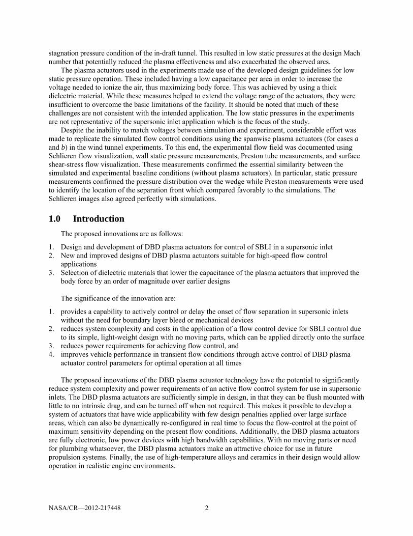
Figure 10 shows photographs of the plasma actuators while operating in the Mach 1.5 flow. The top photograph shows operation at a relatively ideal condition where a majority of the plasma (purple in the image) is on the downstream (left in the image) side of the exposed electrode. The voltage to the actuator in this image is approximately 50 kVp-p. At 50 kV, we could not detect a reduction in the size of the separated flow region, or a change in the location of the shock near the wedge, which would be an indication of a reduction in the flow separation.
The lower photograph in Figure 10 documents the plasma formation when the actuator voltage was increased beyond 50 kVp-p. This shows plasma formation around the sides and on the upstream edge (right side of the electrode in the image). A point plasma streamer is evident on the spanwise centerline of the test section. This emanates from the edge of the metal floor of the tunnel. A further increase in the actuator voltage would result in a constricted arc to the edge of the metal floor of the tunnel. This occurred at voltages that were well under the 75 kV that the flow simulation indicated was necessary to eliminate the flow separation.
Attempts were made to increase the body force by increasing the AC frequency of the plasma actuator over a range from 1 to 6.5 kHz. The body force scales linearly with the AC frequency. However we could not fully compensate for the difference in the AC voltage, in which the body force scales
nonlinearly 53ACV . .
Figure 10.—Photographs of the plasma actuators near the wedge at two different voltages at
Mach 1.5 flow.
Flow
Flow

NASA/CR—2012-217448 13
3.2.3 Task 2. Experiments and Simulations Over a Flat Plate With an Impinging Shock at M = 1.5
Simulations were also performed for conditions with an impinging shock caused by a supersonic airfoil placed in the free-stream of the test section. A photograph of the experimental arrangement is shown in the right part of Figure 4.
The flow simulation was similar to that of the wedge flow. It again utilized the Fluent flow solver, with a grid generated using Gambit. The domain for this case can be seen in Figure 11. As before, the calculations used a steady two-dimensional, compressible flow solver that incorporated a shear-stress transport k-ω turbulence model. Results for the impinging wall shock cases are presented as contours of constant Mach number in Figure 12.
The baseline flow for the impinging shock simulation is shown in the left part of Figure 12. The dark blue contours indicate low Mach numbers that suggest the presence of a flow separation region. This coincides with the coincidence of the impinging shock from the leading edge of the suspended airfoil, and the induced shock at the upstream edge of the separated flow region at the wall. A Schlieren visualization for the impinging shock case is shown in the left part of Figure 13. The flow direction is from left to right in the image. The suspended airfoil (shock generator) is out of view in the top left of the image. The boundary layer wall is at the bottom of the image. The impinging shock is clearly visible. The shock turns normal to the wall as it passes into the boundary layer. The reflected shock initially is normal to the wall and then inclines to the Mach angle once it leaves the boundary layer. The right part of Figure 13 overlays the Schlieren image with the Mach contours from the simulation. This shows an excellent agreement between the experiment and simulation with respect to the shock pattern. The height of the boundary layer, signified by the region where the shock is normal to the wall, is also seen to agree well between the experiment and simulation.
Figure 11.—Computational domain used for simulations over a flat plate with an impinging shock.
Figure 12.—Simulations of the flow with an impinging wall shock produced by a supersonic airfoil in the free-stream without DBD plasma actuator (left) and with four series DBD plasma actuators at 75 kV (right).
Flow
Flow Flow

NASA/CR—2012-217448 14
Figure 13.—Schlieren visualization of the baseline impinging shock structure at Mach 1.5 (left) and overlay of
Schlieren visualization and baseline simulation Mach contours (right).
Figure 14.—Photograph of plasma actuator while operating with impinging shock arrangement.
The effect of DBD plasma actuators on controlling the boundary layer separation downstream of the
reflected shock is shown in the right part of Figure 12. The flow simulation incorporated four plasma actuators that were spaced 1 cm apart. The most upstream actuator was located just upstream of the flow separation (dark blue region at the wall in the baseline simulation). The voltage of the plasma actuators was again 75 kV.
The flow simulation with the four plasma actuators indicates that the boundary layer separation was completely suppressed. In this case, compared to the shock-boundary layer interaction produced by the wedge, the four plasma actuators were needed to fully maintain an attached flow. A simulation with two plasma actuators operating at 75 kVp-p, could reduce the extent of the flow separation, but not eliminate it completely.
Again, although the simulation used four plasma actuators that were spaced 1 cm apart, the scale of the experiment made it impossible to replicate. Therefore as with the experiment with the wedge, only a single exposed electrode was used in the experiment.
Figure 14 shows a photograph of the plasma actuator while operating in the Mach 1.5 impinging shock arrangement. The operation is at a relatively ideal condition where a majority of the plasma (purple in the image) is on the downstream (left in the image) side of the exposed electrode. The voltage to the actuator in this image is approximately 50 kVp-p. The Preston tube is also visible on the surface of the wall. This provided an indication of any changes in the flow separation region that were produced by the plasma actuator.
Plasma Actuator
6.5‐deg Shock Generator
FLow
Preston Tube

NASA/CR—2012-217448 15
At 50 kV, we could not detect a reduction in the size of the separated flow region, or a change in the location of the shock near the wedge, which would be an indication of a reduction in the flow separation. Again, any further increase in the actuator voltage would result in a constricted arc to the edge of the metal floor of the tunnel. This occurred at voltages that were well under the 75 kV that the flow simulation indicated was necessary to eliminate the flow separation. As with the wedge experiments, we attempted to compensate for the lower voltage by increasing the AC frequency. This however was not sufficient.
3.2.4 Task 3. Numerical Simulations of Mach 2 Nozzle Flow in a 1515 cm Wind Tunnel With a Shock Generator Using Wind-US
The Wind-US (Ref. 29), a compressible 3-D Reynolds-Averaged Navier-Stokes (RANS) flow solver, was employed to simulate the effect of plasma actuators on a shockwave boundary-layer interaction configuration based on experimental (Ref. 30) and computational (Ref. 31) work done at NASA Glenn. The original work employed vortex generators to control the shock-induced separation. We have repeated the simulation, this time using two different PSVG configurations.
While the Mach number for this case is somewhat higher than originally intended for this work (2.0 versus about 1.5), the 15 cm tunnel configuration was selected because of the quality and availability of both related experimental and computational results. The latter were even achieved using a version of the same solver (Wind-US) intended for the plasma simulations discussed below.
The NASA Glenn test rig consisted of a 15 cm supersonic wind tunnel with a Mach 2.0 nozzle. A shock generator plate was mounted in the tunnel, exactly as in the previous experiments and simulations. At the inflow to the nozzle, the total pressure was given as 15.41 psi, and the total temperature was 538.2 R.
The overall computational geometry is shown in Figure 15. The domain begins with the nozzle inlet at x = 0 ft. The throat is approximately at x = 0.6 ft, and the nozzle exits into the straight duct at roughly x = 1.5 ft. The leading edge of the shock generator plate is at about x = 3.56 ft, and its trailing edge is at x = 4.0 ft (see Fig. 16). The domain ends roughly 6.9 ft downstream of the nozzle inlet. Only half of the tunnel width (0.246 ft—7.5 cm) is modeled (symmetry conditions were employed along the center line).
In keeping with the previous CFD work of Hirt et al. (Ref. 31), and in contrast with the previous experimental work of Hirt and Anderson (Ref. 30), the side wall was modeled as an inviscid wall. Hirt et al. (Ref. 31) found that without this approximation, the boundary layer on the side wall grew unacceptably large and contaminated the results. We therefore followed her practice and used viscous walls only on the top wall, bottom wall, and the shock generator plate.
Figure 15.—Computational domain used for the simulations of the shock wave boundary layer interaction in the NASA Glenn 15 cm tunnel (every 4th spanwise point shown).
NASA/CR—2012-217448 16
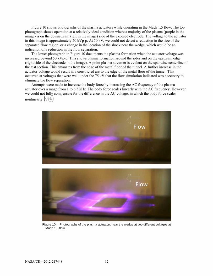
Figure 16.—Viscous wall boundaries in the vicinity of the shock generator plate
(every 4th spanwise point shown).
Figure 17.—Constant Z section of computational mesh in vicinity of shock generator
plate (every other point shown).
The baseline computational mesh used for this work had identical constant-z cross-sections as those
used by Hirt et al. (Ref. 31) for the baseline runs without any vortex generators (thanks go to Drs. Hirt and Georgiadis for working to provide that computational mesh to us). A sample cross-section in the vicinity of the shock plate is shown in Figure 17.
Originally, we considered clustering points in the spanwise direction based on the desired position of the plasma actuators. The final runs, however, used a dense, but uniform, spanwise spacing, since this allowed maximum flexibility in the numbers and positioning of the plasma actuators. The final mesh used for this work consisted of 20.4 million grid points which, for improved computational efficiency on ITAC’s in-house cluster, were split into a total of 43 blocks. This allowed a maximum theoretical parallel efficiency in excess of 95 percent on 40 processors (which is the number that was used).

NASA/CR—2012-217448 17
3.2.4.1 Numerical Methodology
The NPARC Alliance’s Wind-US solver was used to conduct the simulations discussed here. Version 3.0, which was then in alpha testing, and is now nearing the end of beta testing prior to production release, was used. The effects of the plasma actuators were predicted using an ITAC-proprietary extension to the solver, which read in a specified body force field and applied it according to user-specified criteria (e.g., position, orientation, size, and amplification factor). The force field itself was computed by Notre Dame using the in-house models they have developed over the last decade of working with plasma actuators.
Convective terms were computed using the HLLC scheme with second order physical space-based flux interpolation. The van Albada TVD limiter was employed. Block-to-block communication used the so-called “average” coupling algorithm. This has been found to be significantly more stable than the default Roe coupling methods. Thus, the timestep could likely have been increased beyond the CFL of 0.7 which was used, but this more conservative number was used in order to avoid any delays due to instability caused by an excessively large time step.
In general, the simulations were run in steady-state mode from scratch for 20,000 steps. Block communication was performed at each step (i.e., “ITERATIONS PER CYCLE 1” was used). Implicit wall boundaries were employed, as was the DQ limiter. An extrapolation boundary condition was employed for the downstream exit, while symmetry was employed at the tunnel centerline (as mentioned above). Viscous walls were assumed to be adiabatic. The Menter Shear Stress Transport (SST) RANS turbulence model was employed for all runs. Notes for the original mesh obtained from Hirt indicate that the initial spacing off the viscous walls corresponds roughly to y+ of 2.
3.2.4.2 Baseline Case
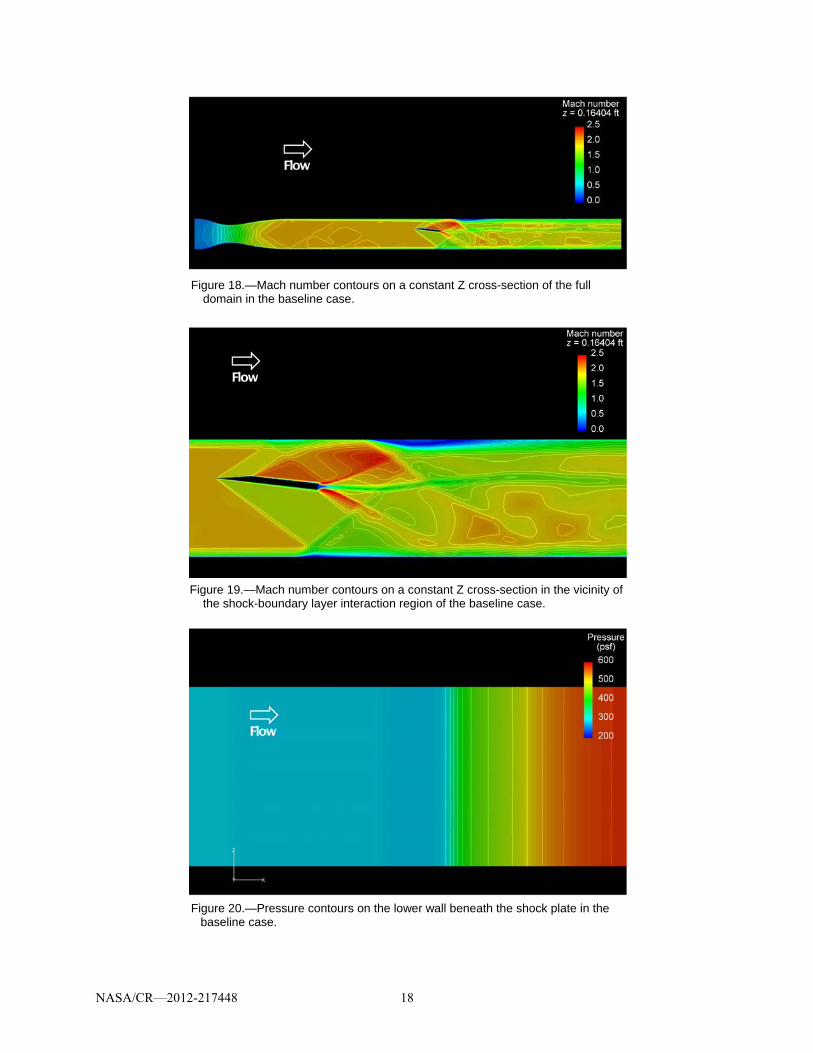
The baseline case, as mentioned above, consisted of the tunnel configuration without any plasma actuation. A representative set of Mach contours in the flow domain is shown in Figure 18. Looking at the region in the immediate vicinity of the shock generator plate in Figure 19, the incoming boundary layer is clearly seen to interact with the well-resolved shock coming of the leading edge of the plate. The resulting small separation region is visible as the blue contours underneath the reflected shock on the lower wall.
Figure 20 shows pressure contours on the lower wall of the tunnel beneath the shock plate. The pressure rise on the right side indicates where the shock from the generator plate meets the boundary layer on the wall. As expected for this baseline case, the flow is essentially two-dimensional. Figure 21 shows the region of separation on the lower wall as revealed by the changing sign of the viscous stress tensor.
Specifically, contours of y
u
are shown. Another way of seeing the same thing is to examine the sign of
the streamwise velocity component a small distance above the wall (2e-5 ft in this case), as shown in Figure 22. Note that the two predicted separation regions agree closely with each other, and again, the two-dimensional nature of this flow is apparent.
A side view (on a constant-Z plane) of streamwise velocity contours is shown in Figure 23. Again, the blue contours at the lower tunnel wall indicate the extent of the shock-induced separation region. This compares extremely well with Figure 9 in the Hirt et al. (Ref. 31) paper (allowing for differences in the viewpoints and the plotting packages). Figure 24 shows a close-up of the streamwise velocity contours underneath the shock generator plate. This view gives a better indication of the extent to which the recirculation region penetrates into the flow.
Table 1 shows boundary layer profiles at several streamwise stations in the flow. The shock is seen to be approaching the top of the boundary layer by x = 3.8 ft. Recirculation is seen at the x = 3.9 and 3.95 locations, and the flow is reattached by the four foot station.
NASA/CR—2012-217448 18
Figure 18.—Mach number contours on a constant Z cross-section of the full domain in the baseline case.
Figure 19.—Mach number contours on a constant Z cross-section in the vicinity of
the shock-boundary layer interaction region of the baseline case.
Figure 20.—Pressure contours on the lower wall beneath the shock plate in the
baseline case.

NASA/CR—2012-217448 19
Figure 21.—Separation region (between black lines) in the baseline case as
indicated by viscous stress on the lower wall.
Figure 22.—Separation region in the baseline case as indicated by streamwise
velocity component near the lower wall.
Figure 23.—Side view of the streamwise velocity contours around the shock-
boundary layer interaction region.

NASA/CR—2012-217448 20
Figure 24.—Streamwise velocity contours in the shock-boundary layer
interaction region in the baseline case.
TABLE 1.—BOUNDARY LAYER PROFILES AT VARIOUS STREAMWISE STATIONS IN THE BASELINE CASE

NASA/CR—2012-217448 21
3.2.4.3 Two Actuator Case
The first case with plasma modeled a configuration with two PSVG actuators. These actuators were aligned streamwise with the flow, but with opposite orientations, so as to create a counter-rotating vortex pair similar to that from the micro-ramps modeled by Hirt et al. (Ref. 31).
The actuators were located on the lower wall of the tunnel between x stations of about 3.54 and 3.63 ft. This corresponds roughly to a position beneath the leading edge of the generator plate. Spanwise, the actuators were positioned at approximately Z = 0.138 ft and Z = 0.19 ft. It must be emphasized that, in this work, no attempt has been made to optimize the position or number of actuators.
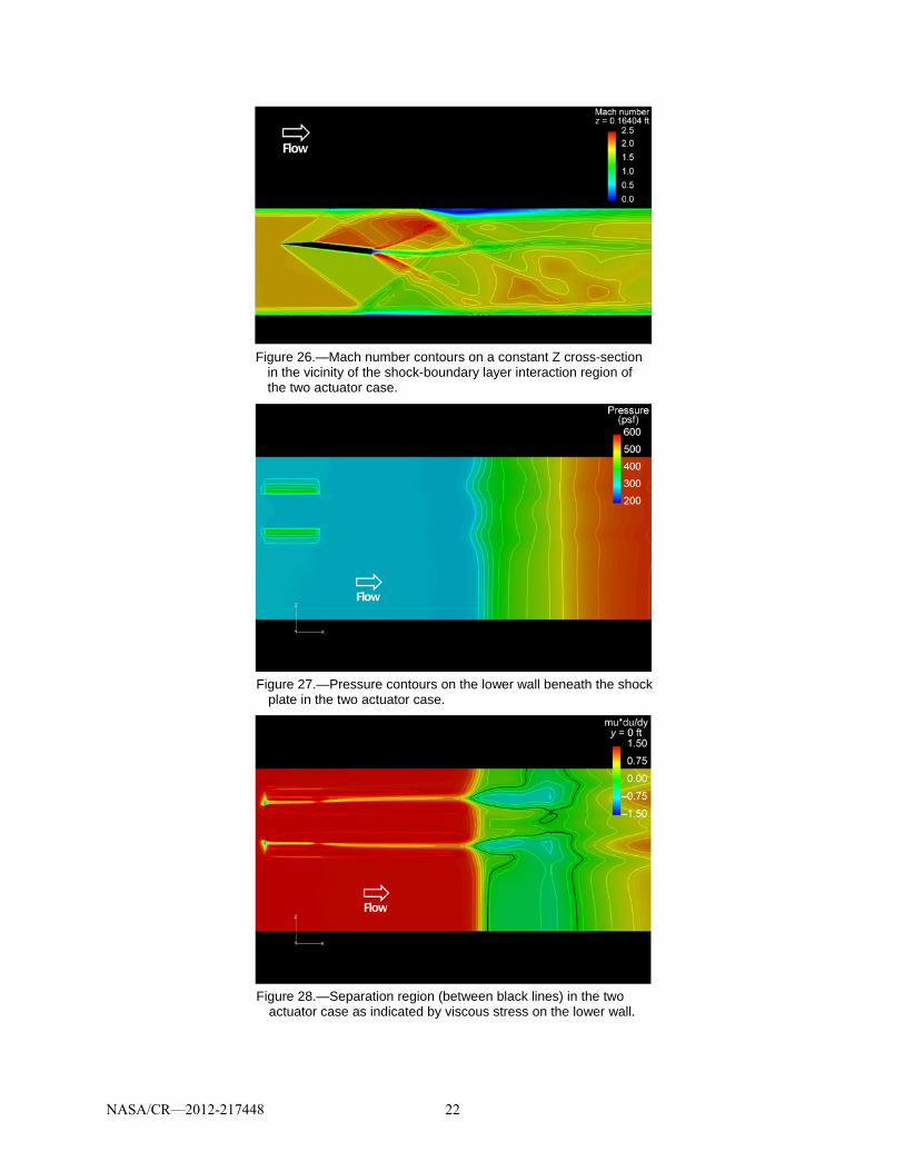
Figures 25 and 26 show Mach number contours on constant-z planes. The spanwise location is at the mid-point between the two actuators. Compared to the corresponding plots of the baseline case, there is not much obvious difference with the addition of the plasma. Taking a closer look, however, reveals that the plasma fields have a noticeable impact on the flow, as will be shown below.
The locations of the plasma actuators are clearly highlighted in the pressure contours on the tunnel wall shown in Figure 27. The shock-boundary layer interaction region is shown to no longer be completely two-dimensional, as it was in the baseline case.
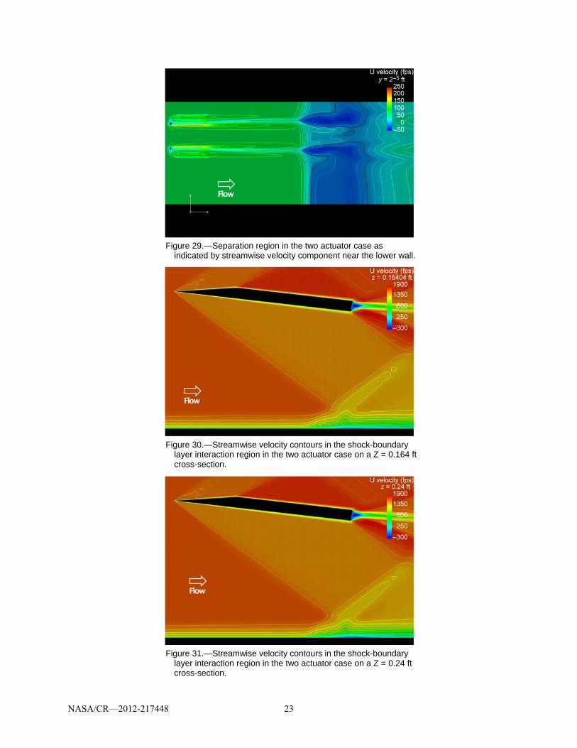
The impact of the twin actuators on the separation is more dramatic, as shown in Figures 28 and 29. Compared to the baseline case, the case with two actuators has increased separation directly behind each actuator, but almost eliminated it in an area between the two. If an actuator configuration can be devised which minimizes the former and maximized the latter, then this technology could be a highly effective means to control shock-induced separation.
Figures 30 and 31 show side views of contours of streamwise velocity. The two z-locations correspond to a plane directly between the two actuators and another almost at the centerline of the test section (modeled with symmetry in the current simulations). Compared to the original baseline plot of the same thing (Fig. 24), both plots show a reduced region of separation.
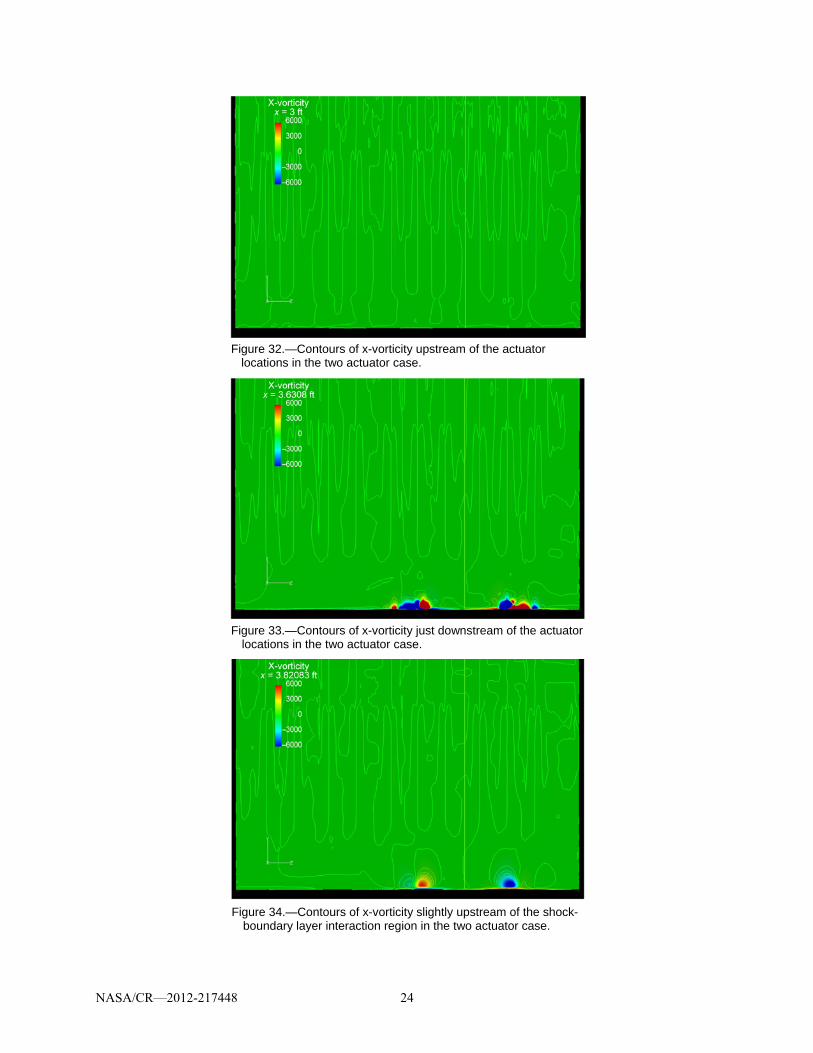
The effect of the plasma actuators on the streamwise component of vorticity is explored next. Figures 32, 33, and 34 show cross-section beginning with one significantly upstream of the actuation region and ending slightly upstream of the shock impingement region. As expected, no significant vorticity is present in the upstream plot (Fig. 32). The plane just downstream of the actuators (Fig. 33), however, shows a strong impact from the plasma fields.
The final plot in this sequence (Fig. 34), which corresponds to a location somewhat upstream of the shock impingement location. At this point, the effect of the plasma actuators can be seen in the presence of two primary counter-rotating vortices. There are hints in the figure of secondary vortices also, but these are less well resolved.
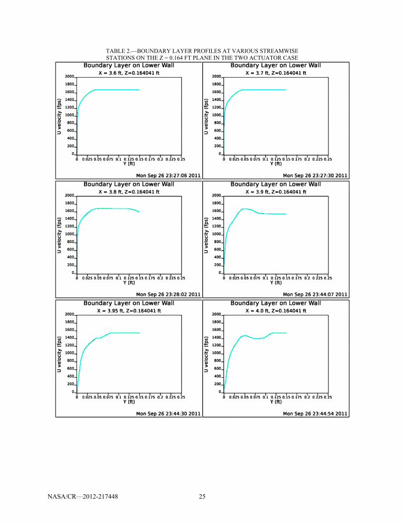
Tables 2 and 3 show boundary layer profiles at various points at two different spanwise locations (again, midway between the actuators and just outboard of the tunnel centerline). The profiles are very similar to the baseline case, but the region of separation is clearly reduced, with reverse flow shown only in the x = 3.95 ft station on the near-centerline plane. At that, the recirculation region is seen only in the automatically chosen scales (with negative values) plotted.
Figure 25.—Mach number contours on a constant Z cross-section of the
full domain in the two actuator case.
NASA/CR—2012-217448 22
Figure 26.—Mach number contours on a constant Z cross-section
in the vicinity of the shock-boundary layer interaction region of the two actuator case.
Figure 27.—Pressure contours on the lower wall beneath the shock
plate in the two actuator case.
Figure 28.—Separation region (between black lines) in the two
actuator case as indicated by viscous stress on the lower wall.
NASA/CR—2012-217448 23
Figure 29.—Separation region in the two actuator case as
indicated by streamwise velocity component near the lower wall.
Figure 30.—Streamwise velocity contours in the shock-boundary
layer interaction region in the two actuator case on a Z = 0.164 ft cross-section.
Figure 31.—Streamwise velocity contours in the shock-boundary
layer interaction region in the two actuator case on a Z = 0.24 ft cross-section.
NASA/CR—2012-217448 24
Figure 32.—Contours of x-vorticity upstream of the actuator
locations in the two actuator case.
Figure 33.—Contours of x-vorticity just downstream of the actuator
locations in the two actuator case.
Figure 34.—Contours of x-vorticity slightly upstream of the shock-
boundary layer interaction region in the two actuator case.
NASA/CR—2012-217448 25
TABLE 2.—BOUNDARY LAYER PROFILES AT VARIOUS STREAMWISE STATIONS ON THE Z = 0.164 FT PLANE IN THE TWO ACTUATOR CASE

NASA/CR—2012-217448 26
TABLE 3.—BOUNDARY LAYER PROFILES AT VARIOUS STREAMWISE STATIONS ON THE Z = 0.24 FT PLANE IN THE TWO ACTUATOR CASE

NASA/CR—2012-217448 27
3.2.4.4 Four Actuator Case
The second plasma actuation case simulated in this work consisted of four actuators placed across the half-span. The streamwise positions were the same as for the two actuator case, with spanwise locations at (approximately) Z-coordinates of 0.05, 0.063, 0.171, and 0.183 ft. The actuators were arranged, similar to before, in a streamwise sense to create pairs of counter-rotating vortices. Again, it must be emphasized that no attempt was made to optimize the placement of these actuators for this work.
Figures 35 and 36 represent the Mach number contours on a constant-z cross-section in the four actuator flowfield. Whereas the same location in the two actuator case corresponded to a region of high benefit from the actuation (i.e., the flow separation was effectively eliminated at this spanwise location), for the four actuator case, this is close to the worst location to plot (as will be shown below). While not easily seen on Figure 35, a close inspection of Figure 36 reveals a larger and stronger region of separation than shown on the previous Mach number contour plots. The location of the actuators and their effect on wall pressure levels is shown in Figure 37. In this figure, clearly the actuators are having an effect on the shock-impingement region. The effect appears to be roughly similar to that seen in the two actuator case.
Figure 35.—Mach number contours on a constant Z cross-section of the full
domain in the four actuator case.
Figure 36.—Mach number contours on a constant Z cross-section in the vicinity
of the shock-boundary layer interaction region of the four actuator case.

NASA/CR—2012-217448 28
Figure 37.—Pressure contours on the lower wall beneath the shock plate in
the four actuator case. The separation region at the lower wall for this case is visualized in Figures 38 and 39. Comparing
this result to that of the two actuator case (Figs. 28 and 29) hints that the current arrangement of actuators could be significantly improved. Specifically, while both plots show a reduction of separation in some regions behind the actuators, the pairing of the actuators (with a relatively small gap between them) appears to be limiting the beneficial effects. Instead, these plots suggest that perhaps a uniform distribution would provide better results.
The streamwise velocity contour plots shown in Figures 40 and 41 indicate the extent of the separation region. As noted before (in the above discussion of the Mach number contours), the two spanwise locations shown are not the best choices for highlighting the benefits of plasma actuators. The first, at Z = 0.164 ft is located very near the location of greatest separation. Compared to the earlier plots from the baseline case and the two actuator case, the recirculation extends further into the flow and is clearly more intense. The second location, near the centerline, is not so obviously bad, but still exhibits noticeable separation in the shock-boundary layer interaction region.
The behavior of the streamwise component of vorticity is shown in Figures 42 to 44. As before, the region upstream of the actuators shows no significant vorticity. A complex set of irregular counter-rotating vortices is shown immediately downstream of the actuators. By the time that the flow reaches the shock-impingement region, however, these counter-rotating vortices have resolved themselves into a dominant pair, with two secondary pairs outboard of them, and (perhaps) a tertiary pair inboard of the dominant set (here, inboard and outboard are defined by the locations of the primary vortex pair and do not refer to the tunnel configuration). As mentioned before, it appears plausible that a different arrangement of actuators could be designed which would have a greater beneficial effect on the recirculation region.
The negative effects on recirculation that are possible with plasma actuation are illustrated in Table 4. These velocity profiles are taken from the Z = 0.164 ft spanwise station, which represents nearly a worst-case scenario for the current runs. The significant strengthening of the recirculation is readily apparent. On the other hand, Table 5 represents a much more benign location, with the profiles more similar to those seen in the baseline case.
The three cases, therefore establish that plasma actuation with the actuators aligned streamwise with the flow, could potentially have beneficial effects. To achieve these effects, however, the positioning of the actuators must be optimized, or there is a risk of achieving the opposite of what is intended.

NASA/CR—2012-217448 29
Figure 38.—Separation region (between black lines) in the four actuator
case as indicated by viscous stress on the lower wall.
Figure 39.—Separation region in the four actuator case as indicated by
streamwise velocity component near the lower wall.
Figure 40.—Streamwise velocity contours in the shock-boundary
layer interaction region in the four actuator case on a Z = 0.164 ft cross-section.

NASA/CR—2012-217448 30
Figure 41.—Streamwise velocity contours in the shock-boundary
layer interaction region in the four actuator case on a Z = 0.24 ft cross-section.
Figure 42.—Contours of x-vorticity upstream of the actuator locations
in the four actuator case.
Figure 43.—Contours of x-vorticity just downstream of the actuator
locations in the four actuator case.

NASA/CR—2012-217448 31
Figure 44.—Contours of x-vorticity slightly upstream of the shock-
boundary layer interaction region in the four actuator case.
TABLE 4.—BOUNDARY LAYER PROFILES AT VARIOUS STREAMWISE STATIONS ON THE Z = 0.164 FT PLANE IN THE FOUR ACTUATOR CASE

NASA/CR—2012-217448 32
TABLE 5.—BOUNDARY LAYER PROFILES AT VARIOUS STREAMWISE STATIONS ON THE Z = 0.24 FT PLANE IN THE FOUR ACTUATOR CASE
4.0 Conclusions
The research investigated the potential for DBD plasma flow control to suppress flow separation caused by an impinging shock in a turbulent boundary layer. The investigation involved both computer flow simulations and experiments. Both of these included two configurations of DBD plasma flow control. In addition, two shock-boundary layer interaction configurations were examined. One was produced by the presence of a 12 wedge on the wall in the boundary layer. The other was produced by a supersonic airfoil that was suspended in the free-stream. The experimental flow field was documented using Schlieren flow visualization, wall static pressure measurements, Preston tube measurements, and surface shear-stress flow visualization. In support of the wind-tunnel measurements, a tunnel modification was implemented to reduce the cross-sectional area. The test section ceiling panel height was reduced 0.5 in. to account for an 8 percent reduction in volumetric pumping capacity resulting from the replacement of the original vacuum pump system with a newer system within the last 5 years. The change in volume capacity had the unanticipated effect of preventing the tunnel from achieving fully sonic flow with the use of the wedge models. By reducing the height from 4.5 to 4 in. it was possible to restore supersonic operation to the facility while maintaining sufficient area for experimentation.

NASA/CR—2012-217448 33
The baseline CFD simulations of the two flow configurations agreed well. The Fluent simulations that included the DBD plasma actuator body force indicated that multiple spanwise actuators in series and at a voltage of 75 kVp-p could fully suppress the flow separation downstream of the shock. Another series of simulations using Wind-US indicated the ability of streamwise plasma actuators to suppress flow separation downstream of the shock, although the resulting flowfield was not as clean as the spanwise actuator case. Considerable effort was made to replicate the simulated plasma control conditions in the experiments. However, we were unable to overcome the wind tunnel constraints of having a low (1 bar) stagnation pressure, and the proximity of metal test section side walls. The former resulted in a low static pressure at the design Mach number that required higher voltages in order to achieve the body force levels used in the CFD simulations. The latter limited the plasma actuator voltages before arcing to the metal structure would occur. The CFD simulations accounted for the effect of the low static pressure on the DBD body force.
The plasma actuators used in the experiments made use of the developed design guidelines for low static pressure operation. These included having a low capacitance per area in order to increase the voltage needed to ionize the air. This was achieved by using a thick dielectric material. The low static pressures in the experiments are not representative of the supersonic inlet application. Therefore in order to overcome the difficulties presented by the low pressures in the current setup, as well as to make the results more relevant to the application, in future work, we propose to use a supersonic test section that will be connected to the UND high-pressure blow-down facility. This would allow stagnation pressures of up to 23 bar, which at the design Mach 1.5, would result in static pressures as high as 6.2 bar. Besides the important demonstration of DBD shock-boundary-layer control, the experiments would provide conditions with which to validate the DBD modeling at high pressures and Mach numbers.
References
1. Gad-el Hak, M., “Flow Control: Passive, Active, and Reactive Flow Management,” Cambridge, University Press, 2000.
2. Klausmeyer, S. and Lin, J., “A Flow Physics Study of Vortex Generators on a Multi-Element Airfoil,” AIAA Paper 96-0548, January 1996.
3. Patel, M., Carver, R., Ng, T.T., and Lisy, F., “Detection and Control of Flow Separation Using Pressure Sensors and Micro-Vortex Generators,” AIAA Paper 2002-0268, January 2002.
4. Anderson, B., H., Tinapple, J., and Surber, L., “Optimal Control of Shock Wave Turbulent Boundary Layer Interactions Using Micro-Array Actuation,” AIAA Paper 2006-3197, June 2006.
5. Kruger, W., “Drag Reduction by Suction of the Boundary Layer Separated Behind Shock Wave Formation at High Mach Numbers,” NACA TM 1168, July 1947.
6. Tillman, T. and Hwang, D., “Drag Reduction on a Large-Scale Nacelle Using a Micro-Blowing Technique,” AIAA Paper 99-0130, January 1999.
7. Sun, M. and Hamdani, H., “Separation Control by Alternating Tangential Blowing/Suction at Multiple Slots,” AIAA Paper 01-0297, January 2001.
8. Glezer, A. and Amitay, M., “Synthetic Jets,” Ann. Rev. of Fluid Mech., V. 34, 2002, pp. 503-529. 9. Corke, T. and Post, M., “Overview of Plasma Actuators: Concepts, Optimization, and Applications,”
AIAA Paper 2005-0563, January 2005. 10. Corke, T.C., Enloe, C., and Wilkinson, S.P., “Dielectric Barrier Discharge Plasma Actuators for Flow
Control,” Ann. Rev. of Fluid Mech., Vol. 42, January 2010. 11. Orlov, D., Corke, T. and Patel, M., Electric Circuit Model for Aerodynamic Plasma Actuator, AIAA-
2006-1206, Jan., 2006. 12. Orlov, D., Modeling and Simulation of Single Dielectric Barrier Discharge Plasma Actuators, Ph.D.,
University of Notre Dame, 2006. 13. B. Mertz, Refinement, validation and implementation of lumped circuit element model for single
dielectric barrier discharge plasma actuators. Ph.D. thesis, University of Notre Dame, 2010. 14. B. Mertz and T. Corke, Single Dielectric Barrier Discharge Plasma Actuator Modeling and
Validation, J. of Fluid Mechanics, 669: 557-583, 2011.

NASA/CR—2012-217448 34
15. F. Thomas, T. Corke, M. Iqbal, A. Kozlov, and D. Schatzman, Optimization of SDBD Plasma Actuators for Active Aerodynamic Flow Control, AIAA J., 47, 9 2169-2177, 2010.
16. Corke, T.C., Post, M. L. and Orlov, D. “Single dielectric barrier discharge plasma enhanced aerodynamics: physics, modeling and applications,” Exp. Fluids 46, p. 1-26, 2009.
17. Enloe, L., McLaughlin, T., VanDyken, R., Kachner, Jumper, E., and Corke, T.C., “Mechanisms and Response of a Single Dielectric Barrier Plasma Actuator: Plasma Morphology,” AIAA Journal, Vol. 42, No. 3, March 2004, pp. 589–594.
18. Enloe, L., McLaughlin, T., VanDyken, R., Kachner, Jumper, E., Corke, T.C., Post, M., and Haddad, O., “Mechanisms and Response of a Single Dielectric Barrier Plasma Actuator: Geometric Effects,” AIAA Journal, Vol. 42, No. 3, March 2004, pp. 595–604.
19. Thomas F.O., Putnam, C.M., and Chu, H.C., “On the Mechanism of Unsteady Shock Oscillation in Shock Wave/Turbulent Boundary Layer Interactions,” Experiments in Fluids 18 (1994) 69-81.
20. Bogdonoff S.M., “Some Experimental Studies of the Separation of Supersonic Boundary Layers. Dept. of Aeronautical Engineering,” Princeton University, Report 336, 1955.
21. Price, A.E. and Stallings, R.L., “Investigation of Turbulent Separated Flows in the Vicinity of Fin Type Protuberances at Supersonic Mach Numbers,” NASA TN D-3840, 1967.
22. Price, A.E. and Stallings, R.L., “Investigation of Turbulent Separated Flows in the Vicinity of Fin Type Protuberances at Supersonic Mach Numbers,” NASA TN D-3840, 1967.
23. Winkelmann, A.E., “Experimental Investigations of a Fin Protuberance Partially Immersed in a Turbulent Boundary Layer at Mach 5,” NOLTR-72-33, 1972.
24. Dolling, D.S. and Murphy, M., Wall Pressure Fluctuations in a Supersonic Separated Compression Ramp Flow field, AIAA Paper 82-0986, 1982.
25. Dolling, D.S. and Or, C. T. “Unsteadiness of the Shock Wave Structure in Attached and Separated Compression Ramp Flows, “Exp. Fluids 3:24-32,” 1985.
26. Erengil, M.E. and Dolling, D.S., “Separation Shock Motion and Ensemble Averaged Wall Pressures in a Mach 5 Compression Ramp Interaction,” AIAA Paper 89-1853.
27. Gramann, R.A. and Dolling, D.S., “Dynamics of Separation and Reattachment in a Mach 5 Unswept Compression Ramp Flow,” AIAA Paper 90-0380.
28. Gramann, R.A. and Dolling, D.S., “Dynamics of the Outgoing Turbulent Boundary Layer in a Mach 5 Compression Ramp Interaction,” AIAA Paper 90-1645.
29. Nelson, C.C.: 2010, “An Overview of the NPARC Alliance's Wind-US Flow Solver,” AIAA Paper 2010-27.
30. Hirt, S.M., Anderson, B.H., “Experimental Investigation of the Application of Microramp Flow Control to an Oblique Shock Interaction,” AIAA Paper 2009-919, Jan 2009.
31. Hirt, S.M., Reich, D.B., and O’Connor, M.B., “Micro-ramp Flow Control for Oblique Shock Interactions: Comparisons of Computational and Experimental Data,” AIAA-2010-4973.

REPORT DOCUMENTATION PAGE Form Approved
OMB No. 0704-0188 The public reporting burden for this collection of information is estimated to average 1 hour per response, including the time for reviewing instructions, searching existing data sources, gathering and maintaining the data needed, and completing and reviewing the collection of information. Send comments regarding this burden estimate or any other aspect of this collection of information, including suggestions for reducing this burden, to Department of Defense, Washington Headquarters Services, Directorate for Information Operations and Reports (0704-0188), 1215 Jefferson Davis Highway, Suite 1204, Arlington, VA 22202-4302. Respondents should be aware that notwithstanding any other provision of law, no person shall be subject to any penalty for failing to comply with a collection of information if it does not display a currently valid OMB control number. PLEASE DO NOT RETURN YOUR FORM TO THE ABOVE ADDRESS.
1. REPORT DATE (DD-MM-YYYY) 01-06-2012
2. REPORT TYPE Final Contractor Report
3. DATES COVERED (From - To) February-September 2011
4. TITLE AND SUBTITLE Shock Generation and Control Using DBD Plasma Actuators SBIR Phase I Final Report
5a. CONTRACT NUMBER NNX11CD87P
5b. GRANT NUMBER
5c. PROGRAM ELEMENT NUMBER
6. AUTHOR(S) Patel, Mehul, P.; Cain, Alan, B.; Nelson, Christopher, C.; Corke, Thomas, C.; Matlis, Eric, H.
5d. PROJECT NUMBER
5e. TASK NUMBER
5f. WORK UNIT NUMBER WBS 561581.02.08.03.47.02.03
7. PERFORMING ORGANIZATION NAME(S) AND ADDRESS(ES) Innovative Technology Applications Company (ITAC), LLC
8. PERFORMING ORGANIZATION REPORT NUMBER E-18178
9. SPONSORING/MONITORING AGENCY NAME(S) AND ADDRESS(ES) National Aeronautics and Space Administration Washington, DC 20546-0001
10. SPONSORING/MONITOR'S ACRONYM(S) NASA
11. SPONSORING/MONITORING REPORT NUMBER NASA/CR-2012-217448
12. DISTRIBUTION/AVAILABILITY STATEMENT Unclassified-Unlimited Subject Categories: 02, 05, 07, 13, and 75 Available electronically at http://www.sti.nasa.gov This publication is available from the NASA Center for AeroSpace Information, 443-757-5802
13. SUPPLEMENTARY NOTES Contract Technical Monitor (COTR): Dr. David E. Ashpis, NASA Glenn Research Center.
14. ABSTRACT This report is the final report of a NASA Phase I SBIR contract, with some revisions to remove company proprietary data. The Shock Boundary Layer Interaction (SBLI) phenomena in a supersonic inlet involve mutual interaction of oblique shocks with boundary layers, forcing the boundary layer to separate from the inlet wall. To improve the inlet efficiency, it is desired to prevent or delay shock-induced boundary layer separation. In this effort, Innovative Technology Applications Company (ITAC), LLC and the University of Notre Dame (UND) jointly investigated the use of dielectric-barrier-discharge (DBD) plasma actuators for control of SBLI in a supersonic inlet. The research investigated the potential for DBD plasma actuators to suppress flow separation caused by a shock in a turbulent boundary layer. The research involved both numerical and experimental investigations of plasma flow control for a few different SBLI configurations: (a) a 12° wedge flow test case at Mach 1.5 (numerical and experimental), (b) an impinging shock test case at Mach 1.5 using an airfoil as a shock generator (numerical and experimental), and (c) a Mach 2.0 nozzle flow case in a simulated 15 X 15 cm wind tunnel with a shock generator (numerical). Numerical studies were performed for all three test cases to examine the feasibility of plasma flow control concepts. These results were used to guide the wind tunnel experiments conducted on the Mach 1.5 12° wedge flow (case a) and the Mach 1.5 impinging shock test case (case b) which were at similar flow conditions as the corresponding numerical studies to obtain experimental evidence of plasma control effects for SBLI control. The experiments also generated data that were used in validating the numerical studies for the baseline cases (without plasma actuators). The experiments were conducted in a Mach 1.5 test section in the University of Notre Dame Hessert Laboratory. The simulation results from cases a and b indicated that multiple spanwise actuators in series and at a voltage of 75 kVp-p could fully suppress the flow separation downstream of the shock. The simulation results from case c showed that the streamwise plasma actuators are highly effective in creating pairs of counter-rotating vortices, much like the mechanical vortex generators, and could also potentially have beneficial effects for SBLI control. However, to achieve these effects, the positioning and the quantity of the DBD actuators used must be optimized. The wind tunnel experiments mapped the baseline flow with good agreement to the numerical simulations. The experimental results were conducted with spanwise actuators for cases a and b, but were limited by the inability to generate a sufficiently high voltage due to arcing in the wind-tunnel test-section. The static pressure in the tunnel was lower than the static pressure in an inlet at flight conditions, promoting arching and degrading the actuator performance. 15. SUBJECT TERMS Jet engines; Aeropropulsion; Plasma; Dielectric Barrier Discharge (DBD); Flow control; Shock waves; Shock Boundary Layer Interaction (SBLI); Inlets; Mixed compression inlets; Wind tunnel 16. SECURITY CLASSIFICATION OF: 17. LIMITATION OF
ABSTRACT UU
18. NUMBER OF PAGES
40
19a. NAME OF RESPONSIBLE PERSON STI Help Desk (email:[email protected])
a. REPORT U
b. ABSTRACT U
c. THIS PAGE U
19b. TELEPHONE NUMBER (include area code) 443-757-5802
Standard Form 298 (Rev. 8-98)Prescribed by ANSI Std. Z39-18