Shock Absorber Rebuild Manual - Euro Spares Home … REBUILD.pdf1 Shock Absorber Rebuild Manual...
27
1 Shock Absorber Rebuild Manual Models PODIUM COMP (‘03) PODIUM PRO (’03) PODIUM X (’03) FOX RACING SHOX 130 Hangar Way, Watsonville, CA 95076 831.768.1100 FAX 831.768.9342 Email: [email protected] Website: www.foxracingshox.com
Transcript of Shock Absorber Rebuild Manual - Euro Spares Home … REBUILD.pdf1 Shock Absorber Rebuild Manual...

1
Shock Absorber Rebuild Manual
Models
PODIUM COMP (‘03) PODIUM PRO (’03)
PODIUM X (’03)
FOX RACING SHOX
130 Hangar Way, Watsonville, CA 95076 831.768.1100 FAX 831.768.9342
Email: [email protected] Website: www.foxracingshox.com
2
TABLE OF CONTENTS
Introduction……………………………………… 3 Contact Information…………………………….. 3 Service…………………………………………... 3 Warranty Policy…………………………………. 3 Methods of Payment…………………………….. 4 Methods of Shipping…………………………….. 4 Disclaimer……………………………………….. 4 Consumer Safety………………………………… 4 Removal & Installation…………………………... 4 Recommended Service Intervals…………………. 4 Tools & Materials Required for Rebuild…………. 5 - 6 Rebuild Instructions………………………………. 7 - 27

3
Introduction Congratulations on choosing FOX Racing Shox. In doing so, you have chosen the best suspension in the industry. All FOX Racing Shox products are designed, manufactured and assembled by the finest professionals in the industry. Contact Information FOX Racing Shox Phone: 831.768.1100 130 Hangar Way North America: 800.369.7469 Watsonville, CA 95076 Fax: 831.738.9342 E-mail: [email protected] Website: www.foxracingshox.com Business Hours: Monday-Friday 8:00AM-5:00PM, Pacific Time Service / Warranty 1. Contact FOX Racing Shox at 800.FOX-SHOX (800-369-7469) to obtain a Return
Authorization Number (RAN) and shipping instructions. 2. Satisfactory proof of purchase receipt is required for warranty consideration. 3. Mark the Return Authorization Number (RAN) and the Return Address on the outside
of the box. Send the shock to FOX Racing Shox with the shipping pre-paid by sender. 4. Include a description of the problem, vehicle information (manufacture, year &
model), type of FOX product, spring rate, type of riding, and a return address with daytime phone number.
Warranty Policy: FOX Racing Shox products are covered by a 1-Year Limited Warranty against defects in materials and/or workmanship. Any modifications to the product will void all warranty. This Warranty will be extended to the original retail consumer of an OEM Customer's FOX Racing Shox equipped vehicle and is valid for one year from the original date of purchase from an OEM Customer's authorized dealer. Warranty is limited to the repair or replacement of the FOX Racing Shox product. FOX Racing Shox reserves the right of final decision with regards to all warranty related issues. Warranty is void when damage to the shock has occurred from the following:
• Abuse. • Seal damage due to power washing. • Damage to the exterior finish caused by debris, rocks, or crashes. • Any attempts to disassemble shock absorber. • Modifications. • Non-factory oil use or improper service • Shipping damage or loss (purchase of full insurance is recommended).

4
Methods of Payment VISA, MasterCard and/or Cashier’s Check Methods of Shipping FOX Racing Shox uses UPS Ground Service within the USA. Customer may request UPS Air Service at an extra cost. All non-warranty shipping charges are the customer’s responsibility. Disclaimer FOX Racing Shox is not responsible for any damages to you or others arising from riding, transporting, or other use of your FOX-equipped vehicle. In the event that your shock breaks or malfunctions, FOX Racing Shox shall have no liability or obligation beyond the repair or replacement of your shock, pursuant to the terms outlined in the Service and Warranty provisions of this manual. Consumer Safety RIDING A MOTOR VEHICLE IS DANGEROUS AND CAN RESULT IN SERIOUS INJURY OR DEATH. RIDE RESPONISBLITY AT ALL TIMES.
• Maintain your vehicle and your suspension. • Always wear a helmet, protective clothing and eye protection. • Ride within your limits. • Tread lightly.
Removal & Installation The method for removing and installing your FOX Racing Shox is different for every vehicle. Refer to your vehicle’s service manual for complete instructions. Recommended Service Intervals Your FOX Racing Shox will perform the best if serviced at regular intervals: Every Ride Wash and dry your vehicle and suspension. Every 100 hours Visually inspect shock seals. Every 500 hours or Annually Charge shock oil and seals.

5
Tools & Materials Required for Rebuild
1. Safety Glasses 2. Latex Gloves 3. Lint Free Towels 4. Assembly Lube (lithium based grease) 5. Loctite ™ #271 6. 12” Tie Wrap (“Zip Tie”) 7. MAPP Gas or Propane Torch 8. Fox 1.834 TC Seal Kit Fox P/N 803-00-014-B 9. Fox 5wt. Shock Fluid – 1 Qt. Fox P/N 803-11-000-A

6
10. Fox IFP Depth Setting Tool Fox P/N 803-00-034-A 11. Fox Seal Installation Bullet (5/8”) Fox P/N 398-00-223-A 12. Fox Nitrogen Safety Needle Fox P/N 802-02-001-A 13. 5/8” Shaft Clamps Fox P/N 398-00-051-A 14. Adjustable Wrench 15. Pin Spanner Wrench (3/16” Pins) 16. 3/32” Hex Key (“Allen Wrench”) 17. 5/32” Hex Key (“Allen Wrench”) 18. Scribe or Dental Pick 19. ¼” Flat Blade Screwdriver 20. #2 Phillips Screwdriver 21. ¾” Open End Wrench 22. Standard Pliers 23. Small Needle Nose Pliers 24. Small Internal Snap Ring Pliers (.040 Tip Diameter) 25. ¾” Socket 26. Torque Wrench 27. Torque Driver 28. Soft Faced/Rubber Mallet 29. Nitrogen Tank w/ Regulator 30. Cleaning Solvent 31. Vice w/ Soft Jaws 32. Tape Measure
7
Rebuild Instructions 1. Read through all of these instructions first to familiarize yourself with the
rebuild procedure. Make sure you have a clean work area, and all of the necessary tools are available. Always use proper safety equipment when working on shock absorbers.
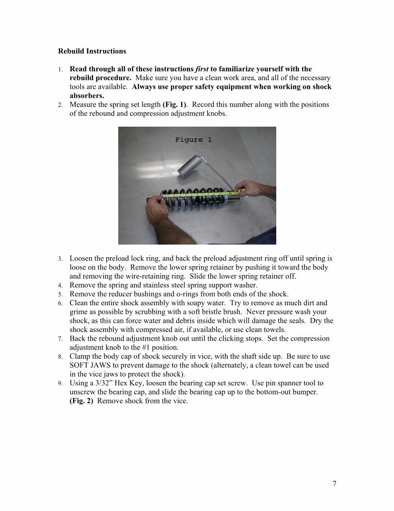
2. Measure the spring set length (Fig. 1). Record this number along with the positions of the rebound and compression adjustment knobs.
3. Loosen the preload lock ring, and back the preload adjustment ring off until spring is loose on the body. Remove the lower spring retainer by pushing it toward the body and removing the wire-retaining ring. Slide the lower spring retainer off.
4. Remove the spring and stainless steel spring support washer. 5. Remove the reducer bushings and o-rings from both ends of the shock. 6. Clean the entire shock assembly with soapy water. Try to remove as much dirt and
grime as possible by scrubbing with a soft bristle brush. Never pressure wash your shock, as this can force water and debris inside which will damage the seals. Dry the shock assembly with compressed air, if available, or use clean towels.
7. Back the rebound adjustment knob out until the clicking stops. Set the compression adjustment knob to the #1 position.
8. Clamp the body cap of shock securely in vice, with the shaft side up. Be sure to use SOFT JAWS to prevent damage to the shock (alternately, a clean towel can be used in the vice jaws to protect the shock).
9. Using a 3/32” Hex Key, loosen the bearing cap set screw. Use pin spanner tool to unscrew the bearing cap, and slide the bearing cap up to the bottom-out bumper. (Fig. 2) Remove shock from the vice.

8
10. Use a 3/32” Hex Key to remove the button head screw from the Fox air valve in the reservoir end cap.
11. Securely clamp Fox Nitrogen Safety Needle in vice. CAUTION! Point air valve away from face and body when charging or discharging any shock.
12. Insert the Fox Safety Needle squarely into center of gas valve. (Fig. 3) 13. Using a blunt object, depress the air valve core to release pressure. (Fig. 3)
14. When the shock is fully discharged, pull reservoir away from the Fox Safety Needle in a straight, smooth motion.
15. Clamp the body cap of the shock securely in vice with shaft side up. 16. Gently tap the reservoir end cap with a rubber mallet to expose the wire-retaining
ring. Locate the end of the ring and push inward with fingertip. Remove the retaining ring. A scribe or dental pick can also be used for this step, but use extreme caution not to scratch the bore of the reservoir tube. (Fig. 4)

9
17. Use pliers to grab flats of the gas valve of reservoir cap. Extract cap from reservoir tube using a twisting motion. Set reservoir cap aside on a clean, lint free paper towel.
18. Using your fingertips, depress the bearing into the body tube to expose the wire-retaining ring. Locate the end of the ring and push inward with your fingertip. Remove retaining ring. A scribe or dental pick can also be used for this step, but use extreme caution not to scratch the bore of the body tube. (Fig. 5)
19. Align the slot of the IFP Depth Setting Tool with the end of the IFP (Internal Floating Piston). Insert the IFP Depth Setting tool into reservoir and rotate 90 degrees to engage the IFP. Push the IFP Depth Setting Tool until the IFP bottoms out inside of reservoir. This will cause shaft assembly to be pushed out of the body tube. (Fig. 6) Remove the shaft assembly from the body tube, and place on a clean, lint free paper towel. Remove the shock from the vice and pour shock oil from body tube into a proper disposal container. DO NOT RE-USE OLD SHOCK OIL.

10
20. Clamp the body cap of the shock securely in vice with the open end of the body tube. 21. Gently pull the IFP out of the reservoir tube using the IFP Depth Setting Tool (Fig.
7), and place it on a clean, lint free towel. Remove the shock from the vice and pour shock oil from body and reservoir tubes into a proper disposal container. DO NOT RE-USE OLD SHOCK OIL. Take several sheets of clean, lint free paper towels and stuff them into the body and reservoir tubes. (This is done to prevent residual oil from dripping out of body and reservoir tubes.)
22. Remove the IFP o-ring using a scribe or dental pick. Use extreme caution not to scratch the o-ring groove. Scratching the o-ring groove will compromise the performance of your shock. Place the IFP on clean, lint free paper towel.
23. Push the compression damping (CD) housing into the reservoir tube to expose the wire-retaining ring. Locate the end of the ring and push inward with fingertip. Remove retaining ring. A scribe or dental pick can also be used for this step, but use extreme caution not to scratch the bore of the reservoir tube. (Fig. 8)

11
24. Gently pull the CD housing out of reservoir tube using a twisting motion. Do not pull directly on the hose. Place reservoir tube on clean, lint free paper towel.
25. Push the end of a 3/32” Hex Key through the small access hole in the side of the CD housing to unseat the wire retaining ring that secures the damp plate assembly. Use a pointed tool such as a scribe or dental pick to remove the retaining ring. Use extreme caution not to scratch the bore of the CD housing. (Fig. 9)
26. Insert a 5/32” Hex Key into the screw head of the damp plate. Remove damp plate by twisting clockwise. (Fig. 10) Place the damp plate assembly on a clean, lint free paper towel.

12
27. Remove damp plate sealing o-ring using a scribe or dental pick. Use extreme caution not to scratch the o-ring groove. Scratching the o-ring groove will compromise the performance of your shock.
28. Check to make sure the compression adjustment knob is set to the #1 position. Insert a 5/32” Hex Key into the largest hole in the side of the CD housing to keep the knob from turning. Use a 3/32” Hex Key to remove the screw that secures the compression adjuster knob. (Fig. 11)
29. Remove the compression adjustment knob, o-ring, clicker balls (2), and springs (2). 30. Remove 5/32” Hex Key from CD housing. 31. Push on the protruding adjuster drum stem to remove it from CD housing. (Fig. 12)

13
32. Remove the adjuster drum sealing o-ring using a scribe or dental pick. Use extreme caution not to scratch o-ring groove. Clean the adjuster drum with cleaning solvent.
33. Remove the paper towels from the body tube and reservoir. Clean the body tube, reservoir tube, IFP, and CD housing thoroughly with solvent. Dry with compressed air in a well ventilated area. If compressed air is not available, dry parts using clean, lint free paper towels and let sit in a well-ventilated area to allow the solvents to evaporate.
34. Lubricate the new adjuster drum o-ring with assembly lube and carefully install it onto the drum. Check to make sure the o-ring is not twisted and is installed correctly.
35. Insert the adjuster drum into CD housing using even pressure to avoid damaging the o-ring. When the adjuster drum is seated properly, the adjuster drum should be flush with the inside surface of the CD housing. (Fig. 13) Check to make sure the drum rotates freely in the bore, and orient the largest cavity of the adjuster drum with the bleed hole (large hole) in the CD housing.
36. Lubricate and carefully install the damp plate sealing o-ring inside the CD housing. Make sure o-ring is properly seated.

14
37. Insert the damp plate assembly into CD housing with the 5/32” hex head facing out. Align the slot at top of damp plate with the bleed hole in the CD housing. (Fig. 14) Seat the damp plate into CD housing, using even pressure in order to not damage the o-ring. Continue applying pressure to damp plate until it bottoms in CD housing. Insert the wire-retaining ring. The end of the retaining ring should be aligned with the access hole in the side of CD housing. This is done to ensure ease of future service on your shock. Check to make sure the retaining ring is properly seated in groove. You may need to use a 5/32” hex key to twist the damp plate assembly clockwise slightly to get the wire ring to seat fully.
38. Fill the two holes that are on either side of the adjuster-drum stub with assembly grease. Insert one new spring into each hole. Place one new clicker ball in the center of each spring. Orient the #1 position of knob with the position indicator of the CD housing. (Fig. 15) Install the compression adjustment knob onto adjuster-drum stub. Apply even pressure on knob and press down completely. The clicker balls should recess down into the holes. If they don’t, slowly remove the knob, and re-seat the clicker balls and try again. Once knob is in position, insert a 5/32 inch Hex Key into the bleed hole of the CD housing. Secure knob with flat head screw using a 3/32 inch Hex Key. Install dust shield o-ring by stretching it over the top of the compression adjuster knob.

15
39. Remove the CD housing outer o-ring. Use extreme caution to avoid scratching the o-ring groove. Lubricate the new o-ring with assembly lube, and install it onto the housing.
40. Check the bore of reservoir for any visible signs of wear or damage. Insert the CD housing into the end of the reservoir with the large chamfer on outside edge (Some reservoirs will not have this chamfer. Orientation is not critical on these reservoirs). (Fig. 16) Push the CD housing far enough into the reservoir to expose the CD housing retaining ring groove. Insert the retaining ring into groove. Check to make sure ring is properly seated. Pull CD housing out of reservoir until it engages securely with retaining ring.
41. Set body assembly aside on a clean, lint free paper towel. 42. Clamp the shaft eyelet securely in vice with the piston end up. 43. Using a ¼” Flat Blade Screwdriver (newer jets use a 5/32 internal hex), remove
rebound jet from end of shaft by rotating it in a counter-clockwise direction. (Fig. 17)

16
44. Using a ¾” wrench, remove piston lock nut from end of shaft. 45. Slide only the tip of Phillips Head Screwdriver into hole at end of shaft. Hold the
piston assembly under the top-out plate and lift upwards. Slide the piston assembly onto the shaft of the Screwdriver. Remove the Screwdriver from shock shaft while supporting the piston assembly. (Fig. 18) Slide a 12-inch tie wrap through the entire piston assembly. Secure the two ends of the zip tie together and remove the screwdriver. There are many pieces to the piston assembly, and the assembly order of these pieces is critical to the proper performance of your shock. This step ensures that the proper order is kept. Place piston assembly on a clean, lint free paper towel.
46. Slide bearing assembly off of shaft. Use extreme caution not to scratch inside of the bearing assembly when passing it over the threads at end of shaft. (Fig. 20)

17
47. Slide the bearing cap and bottom out bumper off of the shaft. 48. Using proper shaft clamps, mount shaft securely in vice. (Fig. 21) A very high level
of clamping force is required to prevent shaft from spinning in clamps. Allowing the shaft to spin in clamps can cause permanent damage to the shaft and may cause the shock to leak.
49. Heat eyelet flange with a torch to loosen the thread-locking compound that secures the eyelet to the shaft. (Fig. 21) Extreme caution is to be used when operating a torch. Refer to the torch manufacturers owner’s manual for proper operation instructions. Follow all safety guidelines.
50. Use an adjustable wrench to loosen the eyelet from shaft. (Fig. 22) If shaft begins to spin, increase clamping force of vice and repeat previous step. Do NOT remove eyelet completely. Once eyelet is loose, allow it to cool before further handling.

18
51. Once the eyelet has been given sufficient time to cool, use an adjustable wrench to remove it from the shaft. Clean the thread-locking compound from eyelet and shaft threads, and set it aside.
52. Using a scribe or dental pick, push the exposed end of the rebound metering rod into the shock shaft, until it comes out of the piston assembly end. Wipe off any residual oil that coats the rebound-metering rod and set it aside on a clean, lint free paper towel. Be very careful to avoid damaging the needle that is attached to the end of the metering rod!
53. Use snap ring pliers to remove the retaining ring from the shaft end. (Fig. 23) Use a scribe or dental pick to remove the brass support washer and metering rod o-ring from end of shaft. (Fig. 24) Use extreme caution not to scratch o-ring gland. Clean all thread locking compound from the end of the shaft.
54. Lubricate the new metering rod o-ring and o-ring gland with assembly lube. Install
the o-ring, making sure the o-ring is properly seated in the gland. Install brass support washer, with the stepped side against o-ring. Install the new snap ring. Make sure the rounded side of the snap ring faces the brass support washer. Check to make sure snap ring is properly seated.

19
55. Apply small amount of thread locking compound (Loctite #271) to shaft threads, and screw the eyelet assembly onto the shaft end. Torque eyelet to 35ft/lbs.
56. Remove the shaft from clamps. 57. Using a small pair of needle nose pliers, grab the lip of the bearing cap dust seal. Use
an inward prying motion to remove the seal. (Fig. 25)
58. Using a small pair of needle nose pliers, grab the lip of the U-cup seal in the bearing assembly. Use an inward prying motion to remove the seal. (Fig. 26) Use a scribe or a dental pick to remove the o-ring seal from center of the bearing assembly. (Fig. 27) Use extreme caution when removing seals from bearing assembly. Do not scratch the o-ring groove, or DU bushing. Doing so will compromise the performance of your shock.
59. Thoroughly clean the bearing, bearing cap, and piston assembly with solvent. Dry
with compressed air in a well ventilated area. If compressed air is not available, dry parts using clean, lint free paper towels and let sit in a well ventilated area to allow the remaining solvent to evaporate.
60. Install new dust seal into bearing cap. Seal should be installed with lip protruding from the flat side of the bearing cap. Check to make sure seal is properly seated. If a

20
tool is required to aid in proper seating of seal, use the non-writing end of a pen, or a similar soft, blunt object, to push it in. (Fig. 28)
61. Install the new, well lubricated, o-ring into the bearing housing. Correct o-ring placement is in the groove next to the DU bushing. Check to make sure the seal is properly seated, and is not twisted. If a tool is required to aid in proper seating of o-ring, use the non-writing end of a pen, or a similar soft, blunt object, to push it in.
62. Install the new U-cup seal into bearing. U-cup should be installed so the cupped end is facing the DU bushing inside of bearing. Check to make sure seal is properly seated. If a tool is required to aid in proper seating of U-cup seal, use the non-writing end of a pen, or a similar soft, blunt object, to push it in. (Fig. 29)
63. Clamp shaft eyelet securely in vice, and place seal bullet tool on end of shaft 64. Slide bottom-out bumper onto shaft. The tapered side of the bottom-out bumper
should be facing away from the shaft eyelet. 65. Lubricate the seal bullet tool with assembly lube. Slide the bearing cap onto shaft
with the threaded side facing away from the shaft eyelet. (Fig. 30) This should be done in a single smooth motion to avoid damaging the seal. If seal hangs up on the

21
edge of the shaft, DO NOT FORCE IT ON. Remove the bullet tool, with the bearing cap still attached, from the shaft end. (Fig. 32) Remove the bearing cap from the bullet tool, and repeat this step.
66. Lubricate the bearing assembly seals with an ample amount of assembly lube. Slide
the bearing assembly onto shaft with the threaded side facing the bearing cap. (Fig. 31) This should be done in a single smooth motion to avoid damaging the seals. If a seal hangs up on the edge of the shaft, DO NOT FORCE IT ON. Remove the bullet tool, with the bearing assembly still attached, from the shaft end. (Fig. 32) Remove the bearing assembly from the bullet tool, and repeat this step.
67. Insert the shaft of a phillips head screwdriver through the center of the piston
assembly. The pointed end of the screwdriver should be on the same side as the top-out plate (large, black plate). Cut and remove the tie wrap that was holding the piston assembly together.
68. Hold the piston assembly from underneath the top-out plate and insert the end of the screwdriver into the shock shaft. (Fig. 33) Slide the piston assembly onto the shaft end. Check to make sure the piston assembly is seated properly, and install the piston lock nut. Torque the nut to 25ft/lbs. (Fig. 34)

22
69. Lubricate the flat end of the metering rod with a small amount of assembly lube.
Insert metering rod, flat end first, into the shaft. (Fig. 35) Push needle down into the shaft with a blunt object, until you feel the metering rod push past the o-ring seal. Install the shaft jet using a torque driver. Torque jet to 40in/lbs. Remove shaft assembly from vice and set it aside on a clean, lint free paper towel.
70. Clamp the body cap of the shock securely in the vice, with the open end of the body facing up. Set compression adjustment knob to position #8.
71. Lubricate the new IFP o-ring with an ample amount of assembly lube, and install it onto the IFP.
72. Hold the reservoir tube at a level that is below the shock body tube with the open-end facing up. Fill the reservoir to retaining ring groove with Fox 5wt. shock oil (#803-11-000-A). You should see bubbles rising to oil surface. Wait until bubbling slows or stops completely. If oil level has fallen, add more oil until level is at retaining ring groove. Insert IFP into reservoir. Use a smooth motion and push straight in until o-ring seats into the retaining ring groove, allowing oil to overflow. Set the compression adjustment knob to the #1 position. Use your free hand to wrap new piston band around IFP with the rounded edge out, and push the IFP into the reservoir until the edge is flush with the end of the reservoir. (Fig. 36) Be careful not to pinch the piston band. Set the compression adjustment knob to position #1. Now, holding

23
the reservoir below the body tube with the compression adjuster side up, push IFP into reservoir tube until it bottoms out inside. (Fig. 37) You should see large air bubbles rise to the surface of the oil in the body tube.
73. Fill shock body half way with oil. While still holding the reservoir below the body
tube, very slowly pull back on the IFP. (Fig. 38) Be careful not to pull the IFP out completely. Wait one minute then push the IFP back to the bottom. You should see bubbles rising to the surface inside the body tube. Repeat this process several times until you don’t see any new bubbles inside the body tube.
74. Set compression adjuster to the #3 position. Firmly grip the reservoir hose at the CD housing. With your other hand pull back forcefully on the IFP Depth Setting Tool, until the edge of the IFP is close to being flush with the edge of the reservoir. Stop the IFP in this position. As you pull forcefully on the IFP, you should feel tension as the IFP pulls back. This step is done to open the damp plate circuit and bleed the system. Let the reservoir hang in this position for a minimum of 5 minutes.
75. Hold the reservoir under the body tube with the compression adjuster facing up. Slowly push the IFP into the reservoir until it bottoms out. Set compression adjuster to the #8 position.

24
76. Fill the body tube with oil approximately ½” below the retaining ring groove. Wrap the new piston band around the piston, making sure the rounded edges face out. Insert the shaft assembly into the body tube, allowing oil to overflow. (Fig. 39) Slowly push shaft into body until piston assembly is approximately 1” below oil surface. Slowly pull shaft assembly out of the body until the rebound ports of the shaft are just below the oil surface. If you pull the shaft out too far you will hear a sucking noise when air is pulled in, and will have to start the bleeding process over. Add oil as necessary. Repeat the previous steps until there are no more bubbles rising to the oil surface.
77. Hold the shaft assembly as straight as possible and hit the shaft eyelet a couple of times, squarely from above, with a rubber mallet. (Fig. 40) This is done to momentarily open the shim stack and allow any trapped air to escape. You should see small bubbles rise to the surface. Fill body tube with oil until oil level is flush with edge of body tube. Slowly pull the shaft out until rebound ports are just below the oil surface. If you pull the shaft out too far you will hear a sucking noise when air is pulled in. If this happens, you will have to start the bleeding process over. Add oil as necessary.

25
78. Hold the shaft eyelet with one hand. With other hand, slide the bearing assembly
down the shaft until contact with oil is made. Find the bleed port in bearing assembly, and position it away from your face and body. With one hand, very slowly push the bearing assembly into body tube. Be sure to have a small container in your other hand to catch the excess oil as it flows out of the bleed port in the bearing. Do not allow the shaft to move as you push the bearing in until the bearing makes contact with the piston assembly. Then push bearing and shaft assembly into body tube until it stops at the external o-ring of the bearing assembly. (Fig. 41) With one hand continue applying pressure to the bearing assembly. With other hand, set the compression adjustment knob to the #1 position. As you do this, the bearing and shaft assembly should push further into the body tube. Push the bearing and shaft assembly into the body tube until the retaining ring groove is exposed. (Fig. 42) Install the wire-retaining ring, and check to make sure retaining ring is properly seated.
79. Push the IFP further into the reservoir. As you do this, the shaft and bearing
assembly should rise until the bearing assembly engages with the wire-retaining ring inside the body tube. Remove the IFP depth setting tool by rotating it 90 degrees.
80. Install the reservoir end cap with the Fox air valve facing the outside of the reservoir tube. (Fig. 43) Push down on the reservoir end cap using even pressure, until the retaining ring groove is exposed. (Fig. 44) Install the wire-retaining ring, and check to make sure retaining ring is seated properly. Push the shaft assembly completely into the body tube. If reservoir cap is not properly seated against the retaining clip, tap it gently with a rubber mallet until it snaps into place. Remove shock assembly from vice.

26
81. Securely clamp Fox Nitrogen Safety Needle in the vice. Be sure to point the air valve
away from your face and body. 82. Insert the safety needle squarely into center of Fox air valve, and pressurize the
reservoir to 300psi. (Fig. 45) Continue charging with gas as you pull the reservoir away from the Fox Nitrogen Safety Needle using a smooth, straight motion. Keep the reservoir as straight as possible to prevent the safety needle from bending. As the safety needle is pulled free from the Fox air valve, a popping sound should be heard. CHARGE THE SHOCK USING NITROGEN GAS ONLY. DO NOT FILL WITH ANY OTHER GASSES. Doing so will compromise the performance of your shock and may be EXTREMELY DANGEROUS!
83. Install the button-head screw into the Fox air valve, using a 3/32” Hex Key. 84. Remove the shock from the vice. 85. Clean all oil residue from the shock and reservoir with solvent, and dry with
compressed air in a well-ventilated area. If compressed air is not available, dry the shock and reservoir using clean, lint free paper towels and let sit in a well-ventilated area to allow the solvents to evaporate.
86. Clamp the body cap of shock securely in vice, with shaft end up. Use pin-spanner tool to secure the bearing cap to bearing. Using a 3/32” hex key, tighten the setscrew to lock the bearing cap into place.

27
87. Compress shock completely. (Fig. 46) Roughly 90 pounds of force is required to initiate movement of shaft. Once shock is fully compressed, turn rebound adjustment knob clockwise until it stops. Let go of the shaft. The shaft should extend very slowly (or not at all). Turn rebound adjustment knob counter clockwise and set to the position recorded previously. The shaft should speed up as adjuster is opened.
NOTE: Time permitting, we recommend allowing the shock to sit for 24 hours and repeating step #87. This hold period allows you to re-inspect the shock and identify any possible oil leaks or nitrogen loss before the shock is re-installed.
88. Reinstall the stainless steel spring support washer, the spring, and the spring retainer. Place the wire-retaining ring into the groove on the spring retainer adapter, and seat the spring retainer against it.
89. Thread the spring preload ring down against the spring, and set the preload to the measurement you took when you removed the spring. (Fig. 1) Thread the preload lock ring down against the preload ring, and tighten them together to lock them in place.
90. Set the compression adjustment knob to the position recorded previously. 91. Remove the shock from the vice. 92. Reinstall spherical bearing o-rings and reducers. Congratulations…You’ve completed the servicing of your FOX Racing Shox. Carefully reinstall the shock on your vehicle. Be sure to RIDE SLOWLY in the beginning to ensure the shock and your vehicle’s suspension is performing correctly. Thanks again for choosing FOX Racing Shox.