
Shoal: A Network Architecture for Disaggregated Racksragarwal/pubs/shoal.pdf · Disaggregated racks...
16
Shoal: A Network Architecture for Disaggregated Racks Vishal Shrivastav Cornell University Asaf Valadarsky Hebrew University of Jerusalem Hitesh Ballani Microsoft Research Paolo Costa Microsoft Research Ki Suh Lee Waltz Networks Han Wang Barefoot Networks Rachit Agarwal Cornell University Hakim Weatherspoon Cornell University Abstract Disaggregated racks comprise dense pools of compute, memory and storage blades, all interconnected through an in- ternal network. However, their density poses a unique chal- lenge for the rack’s network: it needs to connect an order of magnitude more resource nodes than today’s racks with- out exceeding the rack’s fixed power budget and without compromising on performance. We present Shoal, a power- efficient yet performant intra-rack network fabric built using fast circuit switches. Such switches consume less power as they have no buffers and no packet inspection mechanism, yet can be reconfigured in nanoseconds. Rack nodes transmit according to a static schedule such that there is no in-network contention without requiring a centralized controller. Shoal’s congestion control leverages the physical fabric to achieve fairness and both bounded worst-case network throughput and queuing. We use an FPGA-based prototype, testbed ex- periments, and simulations to illustrate Shoal’s mechanisms are practical, and can simultaneously achieve high density and high performance: 71% lower power and comparable or higher performance than today’s network designs. 1 Introduction Traditional datacenter use a server-centric architecture in which a number of racks, each comprising tens of servers connected via a top-of-the-rack (ToR) switch, are inter- connected by the datacenter network. However, the end of Dennard’s scaling [18] and the slowdown of Moore’s Law [14] are challenging the long-term sustainability of this architecture [19]. Consequently, a new paradigm has emerged: rack-scale architecture, where a server is replaced by a rack as the unit of computation, with each rack host- ing a number of System-on-Chip (SoC) [15, 35, 65] mi- croservers, each comprising multi-core CPUs integrated with some local memory, combined with separate pools of non- volatile memory, storage and custom compute (e.g., Google TPUs [82], GPGPUs [74, 78] and FPGAs [43]) blades, all interconnected through an internal network. This en- ables resource disaggregation as compute units are decou- pled from memory and storage units. The benefits disag- gregation are well understood in the computer architecture community [5, 41]: it enables fine-grained resource pool- ing and provisioning, lower power consumption and higher density than traditional server-centric architectures, thus en- abling each rack to host hundreds of resource “nodes” (com- pute/memory/storage blades). Several examples of rack- scale architecture have been proposed both in industry (In- tel [72], Facebook [65, 74], Microsoft [43], SeaMicro [79], HPE [28], Google [82]) and academia [5, 6, 15, 27, 35, 41]. Increasing rack density, however, poses new challenges for the rack’s network. Traditional ToR switches can sup- port only around a hundred ports at high speed. Therefore, interconnecting several hundreds or even a thousand nodes requires either a high-port count chassis switch or a num- ber of low-port count switches arranged in a hierarchical topology, e.g., a folded Clos [1]. Such a design, when cou- pled with state-of-the-art protocols [2, 4, 20, 25], can provide high throughput and low latency that could potentially meet the requirements of disaggregated workloads [19]. Unfor- tunately, such packet-switched designs are significantly less power and cost efficient as compared to today’s intra-rack networks (§2). Power is a particular concern as the rack’s to- tal power has a hard limit due to cooling [35, 60], so network inefficiency ultimately limits the density of other resources. The limitations of packet-switched networks have already prompted network designs that leverage circuit switches in datacenters [11,23,24,38,42,53]. Such switches can be opti- cal or electrical, and the fact that they operate at the physical layer with no buffers, no arbitration and no packet inspection mechanisms means they can be cheaper and more power ef- ficient than an equivalent packet switch (§5). Adopting these designs for intra-rack connectivity would thus alleviate the power concern. However, achieving low latency would still be challenging as traditional circuit switches have reconfig- uration delays of the order of few microseconds to even mil- liseconds. Such a solution, thus, would either compromise on performance or still have to rely on a separate packet- switched network to handle latency-sensitive traffic. In sum- mary, adapting existing network solutions to high-density racks would either compromise on power (packet-switched) or on performance (purely circuit-switched). In this paper, we show that it is possible to design a rack-
Transcript of Shoal: A Network Architecture for Disaggregated Racksragarwal/pubs/shoal.pdf · Disaggregated racks...

Shoal: A Network Architecture for Disaggregated Racks
Vishal ShrivastavCornell University
Asaf ValadarskyHebrew University
of Jerusalem
Hitesh BallaniMicrosoft Research
Paolo CostaMicrosoft Research
Ki Suh LeeWaltz Networks
Han WangBarefoot Networks
Rachit AgarwalCornell University
Hakim WeatherspoonCornell University
AbstractDisaggregated racks comprise dense pools of compute,memory and storage blades, all interconnected through an in-ternal network. However, their density poses a unique chal-lenge for the rack’s network: it needs to connect an orderof magnitude more resource nodes than today’s racks with-out exceeding the rack’s fixed power budget and withoutcompromising on performance. We present Shoal, a power-efficient yet performant intra-rack network fabric built usingfast circuit switches. Such switches consume less power asthey have no buffers and no packet inspection mechanism,yet can be reconfigured in nanoseconds. Rack nodes transmitaccording to a static schedule such that there is no in-networkcontention without requiring a centralized controller. Shoal’scongestion control leverages the physical fabric to achievefairness and both bounded worst-case network throughputand queuing. We use an FPGA-based prototype, testbed ex-periments, and simulations to illustrate Shoal’s mechanismsare practical, and can simultaneously achieve high densityand high performance: 71% lower power and comparable orhigher performance than today’s network designs.
1 IntroductionTraditional datacenter use a server-centric architecture inwhich a number of racks, each comprising tens of serversconnected via a top-of-the-rack (ToR) switch, are inter-connected by the datacenter network. However, the endof Dennard’s scaling [18] and the slowdown of Moore’sLaw [14] are challenging the long-term sustainability ofthis architecture [19]. Consequently, a new paradigm hasemerged: rack-scale architecture, where a server is replacedby a rack as the unit of computation, with each rack host-ing a number of System-on-Chip (SoC) [15, 35, 65] mi-croservers, each comprising multi-core CPUs integrated withsome local memory, combined with separate pools of non-volatile memory, storage and custom compute (e.g., GoogleTPUs [82], GPGPUs [74, 78] and FPGAs [43]) blades,all interconnected through an internal network. This en-ables resource disaggregation as compute units are decou-pled from memory and storage units. The benefits disag-gregation are well understood in the computer architecture
community [5, 41]: it enables fine-grained resource pool-ing and provisioning, lower power consumption and higherdensity than traditional server-centric architectures, thus en-abling each rack to host hundreds of resource “nodes” (com-pute/memory/storage blades). Several examples of rack-scale architecture have been proposed both in industry (In-tel [72], Facebook [65, 74], Microsoft [43], SeaMicro [79],HPE [28], Google [82]) and academia [5, 6, 15, 27, 35, 41].
Increasing rack density, however, poses new challengesfor the rack’s network. Traditional ToR switches can sup-port only around a hundred ports at high speed. Therefore,interconnecting several hundreds or even a thousand nodesrequires either a high-port count chassis switch or a num-ber of low-port count switches arranged in a hierarchicaltopology, e.g., a folded Clos [1]. Such a design, when cou-pled with state-of-the-art protocols [2,4,20,25], can providehigh throughput and low latency that could potentially meetthe requirements of disaggregated workloads [19]. Unfor-tunately, such packet-switched designs are significantly lesspower and cost efficient as compared to today’s intra-racknetworks (§2). Power is a particular concern as the rack’s to-tal power has a hard limit due to cooling [35,60], so networkinefficiency ultimately limits the density of other resources.
The limitations of packet-switched networks have alreadyprompted network designs that leverage circuit switches indatacenters [11,23,24,38,42,53]. Such switches can be opti-cal or electrical, and the fact that they operate at the physicallayer with no buffers, no arbitration and no packet inspectionmechanisms means they can be cheaper and more power ef-ficient than an equivalent packet switch (§5). Adopting thesedesigns for intra-rack connectivity would thus alleviate thepower concern. However, achieving low latency would stillbe challenging as traditional circuit switches have reconfig-uration delays of the order of few microseconds to even mil-liseconds. Such a solution, thus, would either compromiseon performance or still have to rely on a separate packet-switched network to handle latency-sensitive traffic. In sum-mary, adapting existing network solutions to high-densityracks would either compromise on power (packet-switched)or on performance (purely circuit-switched).
In this paper, we show that it is possible to design a rack-

scale network that operates comfortably within the rack’spower budget while achieving performance comparable topacket-switched networks. Our work is motivated by fastcircuit switches that can be reconfigured in a few to tensof nanoseconds while still being power-efficient. Theseare available commercially [76] as well as research proto-types [10, 16, 17, 30, 35, 36, 48, 52]. Unfortunately, it is notsufficient to simply take existing circuit-switch-based archi-tectures and upgrade their switches as these architectureswere designed under the assumption of slow reconfigurationtimes. In particular, these solutions rely either on a central-ized controller to reconfigure the switches [11,23,24,35,42,53], which would be infeasible at a nanosecond scale, oron a scheduler-less design with a large congestion controlloop [38], which prevents taking advantage of fast reconfig-uration speeds.
We present Shoal, a power-efficient yet performant net-work fabric for disaggregated racks built using fast circuitswitches. Shoal reconfigures the fabric using a static sched-ule that connects each pair of rack node at an equal rate. Thisavoids the need for a centralized scheduler that can operateat a sub-microsecond granularity. To accommodate dynamictraffic patterns atop a static schedule, traffic from each nodeis uniformly distributed across all rack nodes which then for-ward it to the destination; a form of detour routing. Suchcoordination-free scheduling, first proposed by Chang etal. [9] as an extension of Valiant’s method [50], obviates thecomplexity and latency associated with centralized sched-ulers while guaranteeing the worst-case network throughputacross any traffic pattern [9]. Such scheduling, however,requires that all nodes are connected through what lookslike a single non-blocking switch. To achieve this, Shoal’sfabric uses many low port-count circuit switches connectedin a Clos topology. When reconfigured synchronously, theswitches operate like a single circuit switch. Further, we de-compose the static, equal-rate schedule for the fabric intostatic schedules for the constituent switches.
Overall, this paper makes the following contributions:• We present a network architecture for disaggregated racks
that couples fast circuit switches with the servers’ networkstack to achieve low and predictable latency at low costand power.
• We designed a fabric that uses low port-count circuitswitches to offer the abstraction of a rack-wide circuitswitch. We also scaled the coordination-free schedulingtechnique to operate across the fabric.
• We devised an efficient congestion control mechanism torun atop Shoal’s fabric. This is particularly challenging toachieve due to high multi-pathing—traffic between a pairof nodes is routed through all rack nodes. Shoal lever-ages the observation that the static schedule creates a peri-odic connection between any pair of rack nodes to imple-ment an efficient backpressure-based congestion control,
amenable to hardware implementation.
• We implemented Shoal’s NIC and circuit switch on anFPGA; our prototype achieves small reconfiguration delay(6.4 ns) for the circuit switches and is a faithful implemen-tation of our entire design including the scheduling and thecongestion control mechanisms.
• We incorporated the NIC and the switch prototype intoan end-to-end small-scale rack testbed that comprises sixFPGA-based circuit switches in a leaf-spine topology con-necting eight FPGA-based NICs at end hosts.
Experiments on this small-scale testbed shows that Shoaloffers high bandwidth and low latency; yet our analysis in-dicates that its power can be 71% lower than an equiva-lent packet-switched network. Using a cross-validated sim-ulator, we show that Shoal’s properties hold at scale too.Across datacenter-like workloads, Shoal achieves compara-ble or higher performance than a packet-switched networkusing state-of-the-art protocols [2,25,54], with improved taillatency (up to 2× lower as compared to NDP [25]). Fur-ther, through simulations based on real traces [19], we alsodemonstrate that Shoal can cater to the demands of emergingdisaggregated workloads.
2 MotivationWe first consider how conventional datacenter networkscould be adapted for disaggregated racks and the shortcom-ings of such an approach.Strawman 1. Chassis switches with hundreds of ports, of-ten used at higher levels of a datacenter’s network hierarchy,could connect all rack nodes but at significant cost, power,and space. For example, the Cisco Nexus 7700 switch cansupport 768 ports at 10 Gbps (only 192 at 100 Gbps). Yet,it consumes 4 KW power and occupies 26 RU [61], whichis 26% and 54% of the rack’s power and space budget re-spectively. A rack’s total power has a hard limit of around15 KW due to constraints on power supply density, rackcooling and heat dissipation [35, 60, 66]. We also consid-ered a custom solution involving commodity switches ar-ranged in a Clos topology, which would still consume around8.72 KW to connect 512 nodes (§ 5). The key reason for thisis that packet switching necessitates buffers and arbitrationinside each switch and serialization-deserialization at eachswitch port, which are major contributors (up to 70%) to theswitch’s chip area and package complexity [34, 62], and inturn, its power.Strawman 2. Motivated by the observation that enablinghigh-density racks requires a step change in the power-efficiency of the network, practitioners have attempted tointegrate several very low-port (typically four or six ports)packet switches in the system-on-chip (SoC) of the mi-croserver. Thus, instead of building a ToR-based network,the microservers can be connected to each other using direct-connect topologies prevalent in HPC and super-computing
systems, e.g., a 3D torus [41, 68, 79]. This design signifi-cantly reduces the overall network power consumption as theadditional logic per SoC is small. However, a key drawbackof direct-connect networks is that they have a static topologywhich cannot be reconfigured based on current traffic pat-tern. Hence their performance is workload dependent—fordynamically changing workloads such as datacenter work-loads, it results in routing traffic across several rack nodes,which hurts network throughput and latency (§7.3) and com-plicates routing and congestion control [15].Circuit switching. These strawmans lead to the questionwhether packet-switched networks are well-suited to supporthigh-density racks. On the upside, packet-switched networksoffer excellent performance and allow the network core to beloosely coupled with the servers’ network stack. In datacen-ters and WANs, this has been a good trade-off—the increasedpower of switches is not a key concern yet loose coupling hasallowed the core network technologies to evolve independentof the servers’ network stack. This also allows the networkto be asynchronous, which helps scaling. These benefits,however, do not hold up inside a rack. The physical sizeof a rack means that achieving rack-wide synchronization isfeasible. Further, many density and cost benefits of disag-gregated racks come from the co-design of servers and thenetwork, so independent evolution is not critical.
Instead, we argue that a circuit-switched network offers adifferent set of trade-offs that are more suited to disaggre-gated racks. Compared to a packet switch, circuit switchescan draw less power and be cheaper due to their simplicity,and these gains could grow with future optical switches (§5).Thus, they can better accommodate higher density. On theflip side, circuit switching does necessitate a tight couplingwhere all nodes are synchronized and traffic is explicitlyscheduled. Further, past solutions with slow circuit switcheshave had to rely on a separate packet-switched network tosupport low latency workloads which increases complexityand hurts network manageability. Using fast circuit switcheshelps on the performance front yet makes the schedulingharder. We show that these challenges can be solved at thescale of a rack and it is feasible to build a rack network thatsatisfies its power constraints while achieving performanceon par with a packet-switched network.
3 DesignShoal is a network architecture for disaggregated racks. Itcomprises a network stack at the rack nodes which is tightlycoupled with a circuit-switched physical fabric.
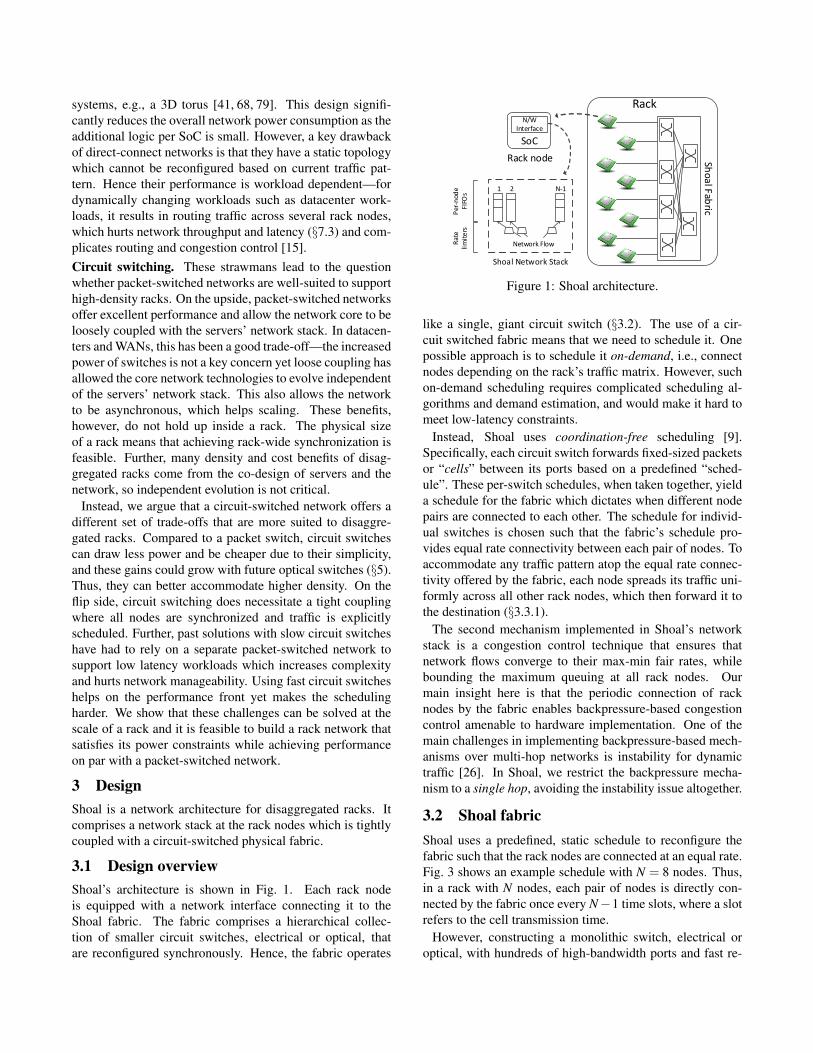
3.1 Design overviewShoal’s architecture is shown in Fig. 1. Each rack nodeis equipped with a network interface connecting it to theShoal fabric. The fabric comprises a hierarchical collec-tion of smaller circuit switches, electrical or optical, thatare reconfigured synchronously. Hence, the fabric operates
Sho
al Fabric
Rack node
N/WInterface
SoC
Shoal Network Stack
1 2 N-1
Network Flow
Rack
Rat
e
limit
ers
Per
-nod
e FI
FOs
Figure 1: Shoal architecture.
like a single, giant circuit switch (§3.2). The use of a cir-cuit switched fabric means that we need to schedule it. Onepossible approach is to schedule it on-demand, i.e., connectnodes depending on the rack’s traffic matrix. However, suchon-demand scheduling requires complicated scheduling al-gorithms and demand estimation, and would make it hard tomeet low-latency constraints.
Instead, Shoal uses coordination-free scheduling [9].Specifically, each circuit switch forwards fixed-sized packetsor “cells” between its ports based on a predefined “sched-ule”. These per-switch schedules, when taken together, yielda schedule for the fabric which dictates when different nodepairs are connected to each other. The schedule for individ-ual switches is chosen such that the fabric’s schedule pro-vides equal rate connectivity between each pair of nodes. Toaccommodate any traffic pattern atop the equal rate connec-tivity offered by the fabric, each node spreads its traffic uni-formly across all other rack nodes, which then forward it tothe destination (§3.3.1).
The second mechanism implemented in Shoal’s networkstack is a congestion control technique that ensures thatnetwork flows converge to their max-min fair rates, whilebounding the maximum queuing at all rack nodes. Ourmain insight here is that the periodic connection of racknodes by the fabric enables backpressure-based congestioncontrol amenable to hardware implementation. One of themain challenges in implementing backpressure-based mech-anisms over multi-hop networks is instability for dynamictraffic [26]. In Shoal, we restrict the backpressure mecha-nism to a single hop, avoiding the instability issue altogether.
3.2 Shoal fabricShoal uses a predefined, static schedule to reconfigure thefabric such that the rack nodes are connected at an equal rate.Fig. 3 shows an example schedule with N = 8 nodes. Thus,in a rack with N nodes, each pair of nodes is directly con-nected by the fabric once every N−1 time slots, where a slotrefers to the cell transmission time.
However, constructing a monolithic switch, electrical oroptical, with hundreds of high-bandwidth ports and fast re-

1 2 3 4 5 6 7 8
Sw
itch
1
a b
c d
Figure 2: Circuit switches in a two-stage Clos topology.
Time slot1 2 3 4 5 6 7
Nod
e
1 2 3 4 5 6 7 82 3 4 5 6 7 8 1· · · · · · · ·· · · · · · · ·8 1 2 3 4 5 6 7
Figure 3: Fabric schedule for a rackwith 8 nodes.
Time slot1 2 3 4 5 6 7
Port
a d c d c d c db c d c d c d cc b a b a b a bd a b a b a b a
Figure 4: Switch 1’s schedule(see Fig. 2 for topology).
configuration is intractable due to fabrication constraints.Instead, Shoal’s fabric comprises low port-count circuitswitches connected in a non-blocking Clos topology. Ar-ranging k-port circuit switches in a two-stage Clos topologyallows the fabric to connect k2
2 nodes. For e.g., using 64-port electrical circuit switches allows us to connect a rackwith 2,048 nodes. Fig. 2 shows six 4-port circuit switchesarranged in such a topology to implement an 8-port fabric.Packets between any two nodes are always routed throughboth stages of the topology, even if the nodes are connectedto the same switch (like nodes 1 and 2 in the figure). Sincethe topology is non-blocking, this does not impact networkthroughput. It ensures, however, that the distance betweenany two nodes is the same which, in turn, aids rack-widetime synchronization (§3.4).
We decompose the schedule of the overall fabric into theschedule for each constituent circuit switch. Consider theexample fabric shown in Fig. 2. Fig. 3 shows the schedulefor this fabric while Fig. 4 shows the schedule for switch1. Each switch’s schedule is contention-free, i.e., at a giveninstant, any port is connected to only one port. This allowsthe switch to do away with any buffers and any mechanismsfor packet inspection or packet arbitration.
3.3 Shoal network stackShoal’s mechanisms operate at the data link layer (layer-2)of the network stack. At each node, Shoal spreads its layer-2traffic uniformly across the rack to ensure guaranteed net-work throughput and implements a congestion control tech-nique that ensures fair bandwidth sharing and low latency.
3.3.1 Forwarding plane
Rack nodes send and receive fixed-sized cells. Packets re-ceived from higher layers are thus fragmented into cells atthe source node and reassembled at the destination. Each cellhas a header (Fig. 5) that contains the corresponding packet’sdestination and other control information.
Cells sourced by a node, irrespective of their destination,are sent to the next node the source is connected to. This uni-formly spreads traffic across all rack nodes. Each node hasa set of FIFO queues, one for every node in the rack. Cellsarriving at an intermediate node are put into the queue corre-sponding to their final destination. This ensures traffic is de-toured through at most one intermediate node. These queuesare served according to the node’s transmission schedule.
We highlight two key aspects of this simple design. First,
uniformly distributing traffic is perfectly suited to the equalrate connectivity provided by the Shoal fabric. This guar-antees the worst-case throughput across any traffic pat-tern [9]—Shoal’s network throughput can be at most 2×worse than that achieved by a hypothetical, rack-wide idealpacket switch. To compensate for this throughput reductiondue to detouring, we double the aggregate bisection band-width of the fabric for Shoal. This is a good trade-off as cir-cuit switches are expected to be cheaper and hence, addingfabric bandwidth is inexpensive; in §5, the cost of the result-ing network is still estimated to be lower than the cost of atraditional packet-switched network.
Second, when the fabric’s schedule connects node i to nodej, the former always transmits a cell; the cell at the headof the queue i→ j is transmitted, otherwise an empty cellis sent. This ensures that each node periodically receives acell from every other node, which enables implementing anefficient backpressure-based congestion control (§3.3.2) andsimple failure detection (§3.5).
3.3.2 Congestion control
Each node sending traffic computes the appropriate rate forits traffic to avoid congesting the network. We begin with adiscussion of the network topology resulting from periodicreconfiguration of the Shoal fabric and its implications forcongestion control, followed by the details of our design.
High Multi-pathing. The periodic reconfiguration ofShoal’s fabric means that the entire network can be seenas an all-to-all mesh with virtual links between each pair ofnodes. For e.g., consider a rack with 8 nodes whose sched-ule is shown in Fig. 3. Since each node is connected to everynode 1/7th of the time, the network provides the illusion of acomplete mesh with virtual links whose capacity is 1/7th ofeach node’s total network bandwidth.
Shoal’s use of detouring means that each node’s trafficis routed through all the rack nodes on their way to theirdestination, resulting in very high multi-pathing. In con-trast, the TCP suite of protocols, including protocols tailoredfor datacenters [2, 51] and recent protocols for RDMA net-works [39,54] only use a single path. Even multi-path exten-sions like MPTCP [44] target scenarios with tens of paths,which is an order of magnitude less than the number of pathsused by traffic in our fabric.
Design insights. Shoal’s congestion control design is basedon three key insights. First, we leverage the fact that the fab-
ric in an N-node rack directly connects each pair of nodesonce every N− 1 time slots. We refer to this interval as anepoch. This means that, when the queues at an intermediatenode grow, it can send a timely backpressure signal to thesender. As we detail below, the periodic nature of this sig-nal coupled with careful design of how a sender reacts to itallows us to bound the queue size across rack nodes.
Second, achieving per-flow fairness with backpressuremechanisms is challenging [54], especially in multi-path sce-narios. In Shoal, a flow refers to all layer-2 packets beingexchanged between a pair of nodes. For network traffic, thisincludes all transport connections between the nodes. Forstorage traffic, this includes all IO between them. Each flowcomprises N− 1 subflows, one corresponding to each inter-mediate node. Shoal achieves max-min fairness across flowsby leveraging the fact that each flow comprises an equalnumber of subflows that are routed uniformly across a sym-metric network topology, so we can achieve per-flow fairnessby ensuring per-subflow fairness. We thus treat each subflowindependently and aim to determine their fair sending rates.The mechanism can also be extended to accomodate otherflow-level sharing policies.
Finally, each subflow traverses two virtual links, either ofwhich can be the bottleneck. For e.g., a subflow i→ j→ kcan either be bottlenecked at the virtual link between nodesi and j, or between nodes j and k. Shoal maintains a queue,Qi j, at node i to store cells destined to node j. We use thelength of the queue Qi j as an indication of the load on thevirtual link between nodes i and j. Note that the node sourc-ing the traffic, node i, can observe the size of the local queueQi j. It, however, also needs to obtain information about thesize of the remote queue Q jk that resides at node j.Congestion control mechanism. We use a subflow fromsource i to destination k through intermediate node j, i→j→ k, as a running example to explain Shoal’s congestioncontrol. When node i sends a cell to node j, it records thesubflow that the cell belongs to. Similarly, when node j re-ceives the cell, it records the index k of the queue that the cellis added to. The next time node j is connected to node i, itembeds the current length of queue Q jk into the cell header:
rate limit feedback ji = len(Q jk) (1)
Each pair of nodes in the rack exchange a cell every epoch,even if there is no actual traffic to be sent. Thus, whennode i sends a cell to node j, it gets feedback regardingthe relevant queue at j within the next epoch. Let us as-sume that node i receives this feedback at time T . At timet (≥ T ), it knows the instantaneous length of its local queueto node j, Qi j(t), and a sample of the length of the remotequeue between nodes j and k, Q jk(T ). The max-min fairsending rate for a subflow is governed by the most bottle-necked link on its path, i.e., the link with the maximum queu-ing. As a result, the next cell for this subflow should onlybe sent after both the queues have had time to drain, i.e.,
at least, max(len(Qi j(T )), len(Q jk(T ))) epochs have passedsince the feedback was received. To achieve this, node i re-leases a cell for this subflow into its local queue for j onlywhen the current length of the queue, after accounting for thetime since the last feedback, exceeds the size of the remotequeue Q jk, i.e., a cell is released into Qi j at time t when,
len(Qi j(t))+(t−T )≥ len(Q jk(T )) (2)
Thus, when a new cell is released into the queue at its source,the previous cell in that queue is guaranteed to have beensent to the remote queue while the previous cell in the remotequeue is guaranteed to have been sent to the destination. Thisensures the invariant that at any given time a subflow has atmost one cell each in both the queue at its source and thequeue at its intermediate node. As a consequence, at anygiven time, the size of each queue Qi j is bounded by:
len(Qi j)≤ outcast degree(i)+ incast degree( j) (3)
Thus, this mechanism ensures that, for each virtual link,Shoal performs fair queuing at cell granularity across all thesubflows sharing that link. This, in turn, results in a tighterdistribution of flow completion times.
Note that while Shoal’s basic design assumes a single traf-fic class for the flows, it can be easily extended to supportmultiple traffic classes as explained in Appendix C.
3.3.3 Improving network latency
While Eq. 3 bounds the queue size, it also highlights one ofthe challenges of detouring: network latency experienced bya cell, while bounded, is impacted by cross-traffic — trafficfrom remote nodes at the cell’s source node and traffic fromlocal node at the cell’s intermediate node. To reduce thisimpact of detouring, we introduce following optimizations:Reducing cell latency at the intermediate node. In addi-tion to queue Q jk, node j also maintains a ready queue R jk.Instead of adding cells to Q jk from local flows that satisfyEq. 2, Shoal adds the corresponding flow ids into the readyqueue R jk. Thus,
len(R jk)≤ outcast degree( j) ≤ N−1 (4)
Shoal then scans the local flow ids in R jk, and adds the corre-sponding cells into the queue Q jk such that at any given timethere is at most one local cell in Q jk. Thus Eq. 3 changes to:
len(Q jk)≤ 1+ incast degree(k) ≤ N (5)
However, to ensure that the rate limit feedback accounts forthe local subflows, Eq. 1 needs to be updated accordingly:
rate limit feedback ji = len(Q jk)+ len(R jk)−1 (6)
The rack network is thus still shared in a max-min fashion,while simultaneously reducing the impact of local traffic onthe latency of remote cells — the latency experienced by aremote cell at any intermediate node is determined only bythe incast degree of cell’s destination.Reducing cell latency at the source node. While Eq. 5 re-duces the impact of detouring at the intermediate node, at

the source node i, the latency for a local cell in Qi j is gov-erned by incast degree of intermediate node j. To reducethe impact of cross traffic (i.e., non-local traffic), Shoal se-lectively adds cells from a new flow to queue Qi j only iflen(Qi j) ≤ 2age, where age is measured in epochs since theflow started. Thus, for the first few epochs, cells will be re-leased to queues over virtual links with low contention, andafterwards will quickly converge to uniform load-balancingusing all virtual links after a max of log(N) epochs. Thisachieves uniform load-balancing for long flows, and hencepreserves Shoal’s throughput bounds, while reducing com-pletion time for short flows.
The impact of these optimizations is evaluated in Fig. 14.
3.3.4 Bounded queuing
Eq. 5 guarantees that at any given time, the size of eachqueue Qi j at node i is bounded by the instantaneous num-ber of flows destined to destination j plus one, with at mostone cell per flow. This queue bound can be used to deter-mine the maximum buffering needed at each node’s networkinterface to accomodate even the worst-case traffic patternof all-to-one incast. In a rack with 512 nodes and 64 B cells,this requires a total buffering per node of 17 MB. Impor-tantly, since Shoal accesses a queue only once every epochfor transmission, and assuming the access latency of off-chipmemory is less than an epoch, Shoal only needs to buffer onecell from each queue Qi j on the on-chip memory, resultingin N− 1 total cells. Using the example above, this leads toon-chip cell buffer size of just 32 KB per node.
3.4 Shoal slots and guard bandShoal operates in a time-slotted fashion. Slots are separatedby a “guard band” during which the switches are reconfig-ured. The guard band also accounts for any errors in racksynchronization.Circuit switch reconfiguration. Shoal uses fast reconfig-urable circuit switches. For example, our prototype imple-ments an FPGA-based circuit switch that can be reconfig-ured in 6.4 ns (§4.1). Electrical circuit switches with fastreconfiguration are also commercially available [76] whilefast optical circuit switches with nanosecond-reconfigurationtime have also been demonstrated [12, 16, 17, 30, 36, 48, 52].Time synchronization. Shoal’s slotted operation requiresthat all rack nodes and switches are time synchronized, i.e.,they agree on when a slot begins and ends. Synchronizinglarge networks is hard, primarily because of high propaga-tion delay and the variability in it. In contrast, fine-grainedrack-wide synchronization is tractable due to their size—atypical rack is only a few meters high which means that, evenwhen using optical transmission with a propagation delay of5 ns/m, the maximum propagation latency across a rack isabout 10-15 ns. Furthermore, the rack can be constructedwith tight tolerances to aid synchronization. For example,if all links are the same length with a tolerance of ± 2 cm,
the propagation delay would vary by a maximum of 0.2 ns.Small physical distance also mitigates the impact of temper-ature variations that could lead to variable propagation delay.
Shoal leverages the WhiteRabbit synchronization tech-nique [32, 37, 40, 45] to achieve synchronization with bit-level precision. WhiteRabbit has been shown to achieve sub-50 picoseconds of synchronization precision [45]. The mainidea is to couple frequency synchronization with a time syn-chronization protocol (§6.1).
Frequency synchronization is achieved by distributing aglobal clock to all the nodes and switches in the rack. Thisglobal clock is generally derived from one of the rack nodes,designated as the clock master. The clock can be dis-tributed explicitly, or implicitly through Synchronized Eth-ernet (SyncE) [75] whereby nodes derive a clock from thedata they receive and use this clock for their transmissions.
In Shoal, time synchronization protocol like PTP [70] orDTP [33] need to run only between the end nodes (and notthe switches). At bootstrap, each switch’s circuits are config-ured according to their respective schedule’s configuration attime slot 1 (e.g. Fig. 4) and they do not change. End nodesthen start running the time synchronization protocol. Onceall the nodes are synchronized to a desired level of precision,they send a bootstrap signal to the switches, followed by ac-tual data according to the fabric schedule (Fig. 3). Switcheson receiving the bootstrap signal start reconfiguring their cir-cuits according to their respective schedules (Fig. 4).Slot size configuration. Overall, the guard band size isthe sum of the reconfiguration delay, variability in propaga-tion and the precision of synchronization. Given the guardband size, the slot size can be configured to balance thetrade-off between latency and throughput: a smaller slot re-duces epoch size resulting in smaller latency, yet it imposeshigher guard band overhead resulting in smaller duty cycleand hence lower throughput.Epoch size and multiple channels. In Shoal, two nodesexchange cells at the interval of an epoch. Therefore, eachqueue drains at the rate of one cell per epoch, meaning asmaller epoch size results in smaller queuing delay. We canreduce the epoch size by taking advantage of the fact that net-work links comprise multiple channels. For e.g., 100 Gbpslinks actually comprise four 25 Gbps channels, which can beswitched independently. Thus, in Shoal, each channel is usedto send cells to a quarter of the rack nodes in parallel. Given afixed slot size (as determined based on guard band size), thisshrinks the epoch size by a quarter (epoch = N−1 slots
num of channels ).Finally, the actual cell size is determined by the slot size andchannel speed, for e.g. a slot size of 20.5 ns (without guardband) will correspond to 64 B cells over a 25 Gbps channel.
3.5 Practical concernsWe now discuss a few practical concerns of the design.Clock and data recovery (CDR). A key challenge for anynetwork relying on fast circuit switches is that each node

source id destination id
rate limit feedback
start-of-packet end-of-packet
last-cell-dropped CRC checksum
sequence number
10 bits 10 bits
22 bits 11 bits
1 bit 1 bit
1 bit 8 bits
Figure 5: Header fields in the 8 B cell header carried by eachcell. Header field sizes assume a max of 1024 rack nodes.
needs to be able to receive traffic from different senders ateach time slot. This requires that, at each time slot, the in-coming bits are sampled appropriately so as to achieve error-free reception. The sampling is done by the Clock and DataRecovery (CDR) circuitry at the receiver and typically takesa few hundred microseconds [46]. However, we note that thisis only a problem when using layer 0 circuit switches thatoperate at the raw physical layer, e.g., when using an opticalcircuit switch. Such a switch imposes no latency overheadbut requires very fast CDR at the receiver in order to achievea reasonable guard band. Recent work has shown that sub-nanosecond CDR is achievable in datacenter settings [13].
Electrical circuit switch can also operate at layer 1 [76].When a circuit is established between ports i→ j, the switchretimes data received on port i before sending it to port j.With such switches, each link in the network is a point-to-point link and thus, fast CDR is not needed. Each switch,however, does need to be equipped with a small buffer to ac-count for any differences in the clocks associated with portsi and j. For Shoal, only a few bits worth of buffering is re-quired since the entire rack is frequency synchronized andthe buffer is only needed to absorb any clock jitter.Cell reordering and reassembly. The sequence number
field in each cell’s header is used to assemble cells in-orderat the destination. Note that Shoal’s congestion control isrobust to reordering, as it operates at the granularity of indi-vidual subflows with a congestion window of size 1. Oncethe cells have been reordered, the start-of-packet andend-of-packet fields in the cell header are used to figureout the packet boundary, and the cells within each packetboundary are then assembled together to re-construct theoriginal packet.Failures. To detect failures, Shoal relies on the fact thata node sends a cell to every other node in the rack, even ifthere is no traffic to send, once every epoch. A path refers tothe set of links and switches through which a node j sends acell to some other node i once every epoch.
When a node i does not receive a cell from a node j in it’scorresponding slot, either due to path failures or node failure,it conservatively infers that node j has failed, and i) stopssending any further cells to j, ii) notifies other nodes that itcan no longer communicate with j, so other nodes stop for-warding cells destined to j via i, iii) forwards the last cell (ifit happens to be i’s local cell) it sent to j via some other node,and iv) discards all the outstanding cells it was supposed to
1 node 1 node-leaf 1 leaf 1 leaf-spine 1 spinelink switch link switch
≈ 1/N ≈ 1/N ≈ 1/√
2N ≈ 2/N ≈ 2√
2/√
N
Table 1: Fraction of failed slots against different failed com-ponents, for a two-stage clos topology. N = no of rack nodes.
forward to j. Shoal relies on a higher layer end-to-end trans-port protocol to recover from the loss of those outstandingcells. Finally, in case of an actual node failure, Shoal againrelies on the transport protocol to recover all the cells thatwere queued to be forwarded at the failed node. If the failednode was the primary clock reference for synchronization,another node needs to take over and remaining nodes seam-lessly switch to it as the new reference. ITU standard forSyncE [75] already supports this.
Note that the failure detection mechanism is symmetric —when node i infers that node j has failed, it immediatelystops sending cells to j, causing j to infer that i has failed,and hence immediately stop sending cells to i. This ensuresthe consistency of Shoal’s closed-loop congestion controlmechanism (§3.3.2), even in the face of failures.
One of the consequences of Shoal’s design is if a node canno longer “directly” communicate with some other node, ei-ther because the other node or the path to it has failed, ithurts node’s throughput as the corresponding slot is markedas failed and hence goes unused (Table 1). We evaluate net-work performance against fraction of failed nodes in §7.3.Scalability. Shoal’s scalability is mainly limited by twofactors: i) On-chip resource consumption on the NIC, inparticular on-chip memory, and ii) epoch size, which con-tributes to network latency. The on-chip memory consump-tion for Shoal scales as Θ(N2log(N)) bits (§4). Even for avery dense rack comprising ∼1000 nodes, this results in amemory consumption only of the order of a megabyte. Onthe other hand, epoch size increases linearly with the num-ber of nodes (§3.4). The impact of increasing epoch size onnetwork latency is evaluated in §7.3.
4 ImplementationIn this section, we discuss our FPGA-based implementationof Shoal’s switch and NIC. We used Bluespec System Ver-ilog [57] (∼1,000 LOCs). Our design runs at a clock speedof 156.25 MHz, thus each clock cycle is 6.4 ns.
4.1 Switch designOur circuit switch operates at layer 1, i.e., data traversing theswitch is routed through the PHY block at the ingress andegress ports (Fig. 6). The mapping between the ingress andegress ports varies at every time slot according to the staticschedule. This mapping is implemented using p different p:1multiplexers, where p is the number of ports in the switch.The control signals to these multiplexers are driven by p reg-isters, one per multiplexer. In each time slot, all the p reg-isters are configured in parallel according to the schedule.

ingress ports egress ports
Altera 10G PHY25 cycles 20 cycles
1 cycle
staticschedule
ShoalSWITCH ingress portegress port
Altera 10G MAC + PHY40 cycles 50 cycles
N-1last cell sent
CELL cache
N-1
Reorder buffers
DRAM
Get intermediatenode to send toin curr timeslot
1 cycle
Extract cell fromCELL cache
corresponding tointermediate node
1 cycle
Piggybackrate limitfeedback
& start sending1 cycle
staticschedule
N-1
N-1N-1
rate limit valuesper local flow perintermediate node
N-1
local flowready queue
everycycle
S
Cell
FIFOCell
SynchronizationFIFO
Initiate storing thereceived cell either
In the Reorder bufferOR
In the CELL queue1 cycle
Update based onrate limit feedback
On-chipMemory
RemoteCell
LocalCell
ShoalNIC
Synchronization FIFOs
4 cycles
4 cycles
CLOCK DOMAIN 2CLOCK DOMAIN 1
1cycle
72
N-1last cell recvd
N-1
Scheduler
&
Packet from host
N-1
CELL queue
chopto cellsflo
w id
Packet to host
reassemble
Figure 6: Switch and NIC implementation with the latencyof each block. Clock cycle is 6.4 ns. N = num of rack nodes.
Hence, the switch reconfiguration delay is simply the timeit takes to update the registers, which can be done in oneclock cycle. Our switch is driven by the clock that drives theinterface to PHY. The interface to 10G Ethernet PHY (XG-MII) runs at 156.25 MHz, resulting in reconfiguration delayof 6.4 ns for our switch. However, for higher link speeds theclock frequency can be higher, for e.g., at 50 Gbps, the inter-face to PHY (LGMII) runs at 390.625 MHz [55], yielding areconfiguration delay of 2.5 ns.
The transmit and receive paths of the switch are located intwo separate clock domains: the transmit path is driven bythe clock distributed throughout the rack, while the receivepath is driven by the clock recovered from the incoming bits.To move data safely across clock domains, we use synchro-nization FIFOs. The total port-to-port latency of our switchis 50 cycles (320 ns): PHY block (45 cycles) + switching (1cycle) + synchronization FIFO (4 cycles).
4.2 NIC designFig. 6. shows the routing and congestion control pipelines
implemented in Shoal’s NIC. Each NIC maintains a cellcache on the on-chip memory, of size N − 1 cells, whichstores the next cell to forward per intermediate node. Re-maining cells sit in the DRAM. The backpressure-basedmechanism underpinning Shoal’s congestion control (§3.3.2)is implemented using two vectors of size N − 1 each, thatrecord the last cell sent (received) to (from) each interme-diate node, and a (N − 1)× (N − 1) matrix that stores the
rate limit feedback received from each intermediate node foreach active local flow. The scheduler uses these data struc-tures to schedule local cells into a ready queue in accordancewith the logic described in § 3.3.2 and § 3.3.3.
NIC latency is dominated by the PHY and MAC IP blocks,with the routing and congestion control logic only adding 4and 5 cycles on the transmit and receive paths, resp. Thus,Shoal’s additional mechanisms impose low overhead.
Appendix B details the resource consumption for Shoal’sFPGA-based implementation.
5 Power and cost implicationsWe now compare the power and cost of a Shoal networkto that of a packet-switched network (PSN). Along with theperformance evaluation in §7, we demonstrate that for 71%lower power and an estimated cost reduction of up to 40%,Shoal’s circuit-switched fabric can reduce tail latency by upto 2× as compared to state-of-the-art congestion control pro-tocols such as NDP [25] atop a PSN.
We analyze a 512-node rack. For a PSN, we considertoday’s packet switches [58, 81], which support 64 portsat 50 Gbps and consume a maximum of 350 W [47, 49].Nodes have 50 Gbps NICs with copper cables (i.e., no opto-electronic transceivers) and connecting them using a non-blocking Folded Clos topology requires 24 such switches.For Shoal, extrapolating from today’s circuit switches [76],we estimate that a 64×50 Gbps circuit switch would con-sume 38.5 W. To compensate for the throughput overheadof detouring packets, each node is equipped with 100 Gbpslinks. So the Shoal network has 48 circuit switches. Thesmall physical size of the actual circuit switch ASIC meansthat the space required for the extra switches is manageable.Based on current SoC trends [59, 73, 79], we expect the NICto be integrated with the CPU on a single SoC and to benefitfrom the same 10× reduction in power consumption. Givena typical power consumption of 12.4 W for today’s 100 GbpsNICs [77], this would lead to an estimated power consump-tion of 1.37 W for the Shoal’s NIC (including 11% overheadas computed in Appendix B) and of 0.62 W for PSN’s. Thus,the total power of the Shoal network is 2.55 KW, 71% lowerthan PSN (resp. 8.72 KW). Lower power density is crit-ical because a rack’s total power has a hard limit around15 KW [35, 60, 66].
Quantifying the cost of the Shoal network is harder as itrequires determining the at-volume cost of circuit switches.Circuit switches can be electrical or optical; today, electri-cal circuit switches are commercially used in scenarios likeHDTV [76] and are capable of fast switching while fast op-tical switches only exist as research prototypes [16, 17, 30,36, 48, 52]. Thus, instead of focussing on absolute costs, weask: how cheap would circuit switches need to be, relativeto equivalent packet switches, for Shoal to offer cost benefitsover PSN? We assume Shoal NICs cost between 2 and 3×PSN NICs to account for the 2× bandwidth and extra func-
tionality they provide. Fig. 11 shows how the relative cost ofthe Shoal network varies as a function of the relative cost ofcircuit switches to packet switches. A Shoal network wouldcost the same as a PSN as long as circuit switches are 33.3–41.6% the cost of packet switches while providing powerand performance gains. If the cost circuit switches was 9.6–18.3% of the cost of packet switches, then Shoal would offera 40% cost reduction. While absolute costs are hard to com-pare as they also depend on several non-technical factors, theanalysis below and our estimations based on hardware costsindicate that at-volume circuit switches could cost as low as15% of equivalent packet switches.
The lack of buffering, arbitration and packet inspection incircuit switches means that they are fundamentally simplerthan packet switches which should mean lower cost. Forelectrical switches, designers often use the switch packagearea as a first-order approximation of switch cost—the ac-tual chip area dictates yield during fabrication and thereforefabrication cost while the total package area dictates the as-sembly and packaging cost. In today’s packet switches 50%of the total area is attributed to memory, 20% to packet pro-cessing logic while 30% is due to serial I/O (SerDes) [62].Electrical circuit switches, by contrast, have no memory andpacket processing, so the first two components have negli-gible contribution. While the amount of I/O bandwidth in acircuit switch remains the same, the actual SerDes is muchsmaller because they are only retiming the signals, insteadof serializing and deserializing data from a high-rate serialchannel to lower-rate parallel channels. Even assuming theSerDes are only halved in size, the total packaged area forcircuit switching could be as low as 15% that of a packetswitch. Overall, this analysis indicates that, with volumemanufacturing, the relative cost of electrical circuit switchescan be low enough for Shoal to simultaneously reduce bothpower and cost as compared to PSN.
Looking ahead, optical circuit switches hold even morepromise: as bandwidth increases beyond 100Gbps per chan-nel, copper transmission becomes noise limited even atintra-rack distances and optical transmission becomes nec-essary [64]. Optical circuit switches further reduce costand power because they obviate the need for expensivetransceivers for opto-electronic conversions. However, a fewtechnical challenges need to be solved for optical switchesto be used in Shoal [7]. For example, while several tech-nologies being studied in the optics community can achievenanosecond switching, practical demonstrations have beenlimited to 64-128 ports [12]. Another longstanding challengeis to achieve fast CDR at layer 0 although recent work hasshown the feasibility of such CDR within 625ps [13].
6 Prototype
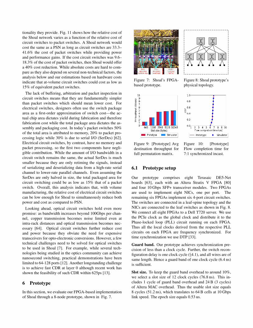
In this section, we evaluate our FPGA-based implementationof Shoal through a 8-node prototype, shown in Fig. 7.
Figure 7: Shoal’s FPGA-based prototype.
Figure 8: Shoal prototype’sphysical topology.
Figure 9: [Prototype] Avgdestination throughput forfull permutation matrix.
Figure 10: [Prototype]Flow completion time for7:1 synchronized incast.
6.1 Prototype setup
Our prototype comprises eight Terasaic DE5-Netboards [63], each with an Altera Stratix V FPGA [80]and four 10 Gbps SFP+ transceiver modules. Two FPGAsare used to implement eight NICs, one per port. Theremaining six FPGAs implement six 4-port circuit switches.The switches are connected in a leaf-spine topology and theNICs are connected to the leaf switches as shown in Fig. 8.We connect all eight FPGAs to a Dell T720 server. We usethe PCIe clock as the global clock and distribute it to thePhase-locked loop (PLL) circuit running on each FPGA.Thus all the local clocks derived from the respective PLLcircuits on each FPGA are frequency synchronized. Fortime synchronization we use DTP [33].
Guard band. Our prototype achieves synchronization pre-cision of less than a clock cycle. Further, the switch recon-figuration delay is one clock cycle (§4.1), and all wires are ofsame length. Hence a guard band of one clock cycle (6.4 ns)is sufficient.
Slot size. To keep the guard band overhead to around 10%,we select a slot size of 12 clock cycles (76.8 ns). This in-cludes 1 cycle of guard band overhead and 24 B (3 cycles)of Altera MAC overhead. Thus the usable slot size equals8 cycles (51.2 ns), which translates to 64 B cells at 10 Gbpslink speed. The epoch size equals 0.53 us.

6.2 Prototype experimentsWe used the prototype to verify that our implementationachieves throughput and latency in accordance with the de-sign. We also use it to cross-validate our simulator which, inturn, is used for a large-scale evaluation regarding the viabil-ity and benefits of a real world deployment of Shoal.
Throughput. We consider a permutation matrix with N = 8flows: each node starts a single long-running flow to anotherrandom node such that each node has exactly one incomingand outgoing flow. For throughput, this is the worst-case traf-fic matrix. In Fig. 9, we show performance in terms of desti-nation throughput, measured as the amount of “useful” cells(i.e., excluding the cells to forward and the empty ones) re-ceived by each destination. For full permutation matrix, thethroughput for Shoal is expected to converge to∼50% of theideal throughput. Interestingly, however, the throughput issignificantly lower for smaller slot sizes, and it converges to-wards 50% only for larger slot sizes. This is an artifact of thesmall scale of our prototype, which causes the node-to-nodecell propagation latency (1.57 us: 40 ns of wire propagationlatency + 3×320 ns of switching latency (dominated mostlyby Altera 10G PHY latency) for three switches along the path+ 576 ns of Altera 10G MAC and PHY latency at the twoend nodes (Fig. 6)) to be higher than the epoch size (0.53 usfor 64 B cells). The problem is that Shoal’s congestion con-trol mechanism prevents a node from sending its next cellto an intermediate node until it has received feedback fromit. Therefore, if the cell propagation latency spans multipleepochs, the overall throughput suffers as senders cannot fullyutilize their outgoing bandwidth. As the slot size increases,the ratio between the cell propagation latency and the epochsize decreases, and this explains why in our prototype thethroughput improves with larger slots. In practice, however,even for modest-sized racks, this issue will not occur as thecell propagation latency will be much smaller than the epochsize, and can be easily accomodated in the schedule as ex-plained in Appendix A.
Latency. We consider all-to-one incast, where seven nodeseach send 448 B of data (seven 64 B cells) to the same des-tination at the same time. Fig. 10 shows the distribution offlow completion time (FCT) of all seven flows. The queue ateach node corresponding to the destination node grows uptoa maximum of 7 (Eq. 5). This results in maximum FCT of6.9 us : 3.76 us of queuing delay plus 2×1.57 us of prop-agation latency. Also note that the difference between thefastest and slowest flow is fairly small (6.05 us vs. 6.9 us),highlighting Shoal’s fair queuing.
Overall, across all experiments, the prototype and simula-tion results were in agreement.
7 SimulationWe complement the prototype experiments in §6 with simu-lations to investigate the scalability of Shoal.
7.1 Simulation setupWe use the packet-level simulator that was cross-validatedagainst our prototype (§6). We simulate a 512-node rack,where each node is equipped with an interface bandwidth of100 Gbps, connected using a full bisection bandwidth Clostopology comprising circuit switches.Guard band. We assume a guard band of 2.75 ns, based ona 2.5 ns switch reconfiguration delay (§4.1) and 0.25 ns to ac-count for any variability in propagation and synchronizationimprecision (§3.4).Slot size. To keep the guard band overhead to around 10%(resulting in max throughput of 90 Gbps), we select the slotsize of 23.25 ns. This results in 20.5 ns of usable slot size.As explained in §3.4, we use the fact that existing 100 Gbpslinks comprise 4×25 Gbps channels, resulting in 4 paralleluplinks and an epoch size of 2.9 us. Finally, usable slot sizeof 20.5 ns translates to 64 B cells at 25 Gbps channel speed.
7.2 MicrobenchmarksWe start with a set of microbenchmarks to verify that thebehavior observed in our testbed holds at large scale too.Throughput. In Fig. 12, we plot the average destinationthroughput, as defined in §6.2, for the permutation trafficmatrix: each communicating node sends and receives oneflow. We vary the number of communicating pairs from 1to 512. As there is no contention at any of the source anddestination nodes, the ideal destination throughput equalsthe maximum interface bandwidth. However, for Shoal,as the number of communicating pairs increases, so doesthe amount of detouring traffic, resulting in the expectedthroughput trend: it starts from the peak value for a singleflow and then monotonically decreases until it halves whenall pairs are communicating (full permutation traffic matrix).Fairness. To verify Shoal’s fairness, we ran several work-loads comprising a variable number of flows from 50 to1,024 with randomly selected sources and destinations. Wecompared the throughput achieved by each flow against itsideal throughput computed using the max-min water-fillingalgorithm [8]. Across all workloads, 99% of the flowsachieve a throughput within 10% of the ideal one. Thisshows that, despite the simplicity of its mechanisms, Shoalclosely approximates max-min fairness.Latency under Incast. We evaluate Shoal under incast, themost challenging traffic pattern for low latency. A set ofnodes send a small flow of size 130 KB each, to the samedestination at the same time. In Fig. 13, we plot the flowcompletion time (FCT) of the slowest flow as well as themean completion time, against increasing number of sendingnodes. As expected, at each intermediate node, the queuecorresponding to the destination node grows linearly withincreasing number of sending nodes, but bounded by the in-cast degree of the destination (Eq. 5). Hence the FCT forthe slowest flow increases linearly and is also the optimal

0.5
1
1.5
2
0.01 0.1 1
Shoal /
PSN
cost
Circuit switch / Packet switch cost
NIC=2xNIC=3x
Figure 11: Relative cost ofShoal network vs. packetswitch network (PSN).
Figure 12: Average desti-nation throughput vs. sizeof permutation matrix.
Figure 13: Flow comple-tion times against synchro-nized short flow incast.
Figure 14: Reduced impactof detouring on latency viaoptimizations in §3.3.3.
maximum FCT under such incast. The mean completiontime coincides with the slowest flow’s FCT, thus highlightingShoal’s fair queuing.
Reducing the impact of detouring on network latency. Toshow that the optimizations described in §3.3.3 indeed im-prove the network latency, we choose two nodes, Node-511(source) and Node-0 (destination), to exchange short flows(20 KB) at regular intervals, and generate random back-ground traffic amongst the remianing nodes. We plot thedistribution of flow completion time (FCT) of short flows ex-changed between nodes 511 and 0 in Fig. 14. The optimiza-tions in §3.3.3 enable Shoal to achieve much smaller andpredictable FCT for target short flows—at the source, Shoalselectively adds cells to local queues where there is low con-tention, and at the intermediate node the queue length isbounded to two regardless of the cross-traffic, as the incastdegree of Node-0 is one (Eq. 5). However, without the op-timizations, the cross-traffic due to detouring significantlyincreases the FCT of target short flows.
7.3 Datacenter workloadsWe now investigate the performance of Shoal in dynamic set-tings, using more realistic workloads.
Workload. We generate a synthetic workload, modeled af-ter published datacenter traces [2, 22]. Flow sizes are heavytailed, drawn from a Pareto distribution with shape parame-ter 1.05 and mean 100 KB [3, 4]. Flows arrive according toa Poisson process and each simulation ends when one mil-lion flows have completed. Flow sources and destinationsare chosen with uniform probability across all nodes (we willstudy the impact of skewed workloads in §7.4).
Network load. We define network load L = FR·N·τ where F
is the mean flow size, R is the per-node bandwidth, N is thenumber of nodes, and τ is the mean inter-arrival flow time,e.g., L = 1 means that, on average, there are N active flows.
Evaluation metric. We evaluate Shoal based on the flowcompletion time (FCT) for short flows (≤100 KB) and av-erage goodput (i.e., throughput after accounting for the 8 Bcell header overhead (§3.5)) for long flows (≥1 MB).
Baseline 1: Direct-connect network. We start with compar-ing Shoal against a rack-scale network using a direct-connect
topology. We arranged the 512 nodes into a 3D torus, whichis the topology used in the AMD SeaMicro 15000-OP [79].As with the Shoal network, we assume an aggregate nodebandwidth of 100 Gbps. We use R2C2 [15] for congestioncontrol. For all values of load, Shoal consistently outper-forms the rack-scale setup up to a factor of 14.9 for tail FCTfor short flows (resp. a factor of 4.8 for avg goodput for longflows). This is due to the multi-hop nature of direct-connecttopologies; it significantly increases the end-to-end latencyas queuing can occur at any hop. Further, node bandwidthis also used to forward traffic originating several hops away,which reduces the overall throughput. This does not occurin Shoal as packets only traverse one hop and the congestioncontrol guarantees bounded queues.
Baseline 2: Packet-switched network. Now we compareShoal against a 512-node packet-switched network (PSN),that connects the nodes using Clos topology with full-bisection bandwidth. The interface bandwidth of each nodeis 50 Gbps. Thus Shoal is provisioned with 2× bandwidth, tocompensate for the throughput overhead of detouring pack-ets. Note that despite the extra bandwidth, Shoal’s power isstill estimated to be lower than that of PSN with a compa-rable or lower cost (§5). As baselines, we use DCTCP [2],NDP [25] and DCQCN [54] as the three state-of-the-art con-gestion control algorithms atop a packet-switched network.The baselines are based on the simulator used in [25]. Weassume 1500 B packets for all of them. DCTCP and DC-QCN use standard ECMP routing, with the congestion win-dow size of 35 packets and queue size of 100 packets. NDPuses packet spraying for routing with initial window size of35 packets and queue size of 12 packets.
As shown in Fig. 15a, at low to moderate load, Shoal ex-hibits an average FCT comparable to DCQCN and DCTCPand slightly higher than NDP. This increase is a consequenceof the use of detouring due to the static schedule ( 3.3.1).However, Shoal outperforms DCTCP and DCQCN in termsof tail FCT for short flows by a factor of 3× at low loadand 2× at high load (resp. outperforms NDP by a factor of1.5× and 2×). The reason for this is three-fold: i) 2× band-width per node in Shoal reduces the serialization delay, ii)selectively adding cells from new flows to local queues withlow contention reduces queuing delay at the source, and iii)

Shoal’s congestion control ensures small and bounded queu-ing at intermediate nodes, thus reducing the queuing delayat intermediate nodes. Shoal also outperforms all three base-lines in terms of long flow goodput (Fig. 15b) by a factor of1.7×, even at high load. This is primarily due to the fact thateach Shoal node is equipped with more bandwidth.Queuing and reordering. To validate our claim that Shoaloperates with very small queues, we plot the maximum queu-ing observed across all nodes in Fig. 16. Even at high load,the maximum queue size is 11 cells (704 B) and the maxi-mum aggregate queue per node is 336 cells (21 KB). Maxi-mum cell reordering within a flow across all nodes and acrossall values of load is 200 KB (Fig. 16).Node failures. We now focus our attention to the impact ofnode failures. We ran the same workload as in the previousexperiments (L = 1) but at the beginning of each experimentwe fail an increasing fraction of nodes (up to 50%). As ex-pected, the goodput decreases linearly (2× worse for 50%failure rate, Fig. 17) because the slots corresponding to thefailed nodes are wasted. We can alleviate this with a moresophisticated mechanism that, on detecting long-term fail-ures, updates the schedule of both rack nodes and switchesto discount the failed nodes. FCT also increases with in-creasing failed nodes, as the number of paths along whichcells from a flow can be sent is reduced, resulting in highersubflow collision and increased queuing. However, Fig. 17shows that even for high failure rate the increase in com-pletion time is rather marginal, e.g., 1.5× for a 40% failurerate (resp. 1.2× for 20% failure rate), thus making Shoalamenable even for sealed rack-scale deployments in whichreplacing failed nodes is not possible.Impact of epoch size on network latency. Next, we studythe impact of epoch size on the FCT. Larger epoch sizeresults in higher latency (§3.4). In the first experiment,we reduced the number of channels from 4×25 Gbps to2×50 Gbps, thus doubling the epoch size. This increased tailFCT by 1.26× at low load (resp. 1.15× at high load). In thesecond experiment, we kept the number of channels constantat 4, and increased the number of nodes to 1,024, again dou-bling the epoch size. In this case, tail FCT at low load grewby 1.28× (resp. 1.2× at high load). This, in turn, shows thatShoal’s performance scales reasonably well with number ofnodes, making it suitable even for very dense racks.
7.4 Disaggregated workloadsFinally, we evaluate the performance of Shoal on disaggre-gated workloads, based on recently published traces [19].These traces comprise a variety of real-world applications,including batch processing, graph processing, interactivequeries, and relational queries. To generate the workloads,we mapped each rack node to one of the server resources(CPU, memory, and storage) and created flows between themfollowing the distributions observed in these traces. Thisyielded a much more skewed workload than the one in §7.3
(a) Flow completion time. (b) Average flow goodput.Figure 15: Flow completion time (short flows≤100 KB) andavg flow goodput (long flows ≥1 MB) vs. traffic load.
Figure 16: Max queue sizeand max cell reordering vs.traffic load.
Figure 17: Short flow99.9p FCT and long flowavg goodput vs. failure.
(a) Flow completion time. (b) Average flow goodput.Figure 18: Flow completion time (short flows≤100 KB) andavg flow goodput (long flows ≥1 MB) for different applica-tions with disaggregated workload.
with more than 84% of the flows being generated among athird of the nodes.
Fig. 18 shows the results for all the six applications, assum-ing a mean inter-arrival time of 12.65 ns. Shoal significantlyoutperforms the baselines in terms of both the tail FCT forshort flows (factor of 2× or more) and avg goodput for longflows (factor of 2.5×). As explained in §7.3, this is due tohigher bandwidth provisioning in Shoal in combination withits highly effective scheduling and congestion control mech-anisms (resulting in maximum queue size of just 10 cellsacross all applications).
These results show the versatility of Shoal and its ability tocarry different types of traffic, including disaggregated work-loads, with high throughput and low latency.

8 DiscussionThe focus of this paper is on the design of a network fordisaggregated racks. Here we discuss a few open questions.Integrating a Shoal rack with rest of the datacenter. Akey question is how to seamlessly integrate a rack-scale net-work, such as Shoal, with the rest of the datacenter, whichmight consist of both disaggregated and traditional racks.Existing rack-scale designs [35] typically use a few racknodes as gateways that are then directly connected to the dat-acenter network. Such a design could be adapted for Shoalas well—the gateway nodes would act as a bridge betweenShoal’s network stack and datacenter-wide network stack,such as TCP/IP over Ethernet. There are, however, severalkey challenges that still remain to be addressed such as theinterplay between different congestion controls and how todesign the interface between IP packets and Shoal cells (e.g.,packet reassembly/fragmentation and encapsulation).Running applications on top of Shoal. Shoal is a link layerarchitecture with support for congestion control. Runningapplications on top of Shoal, however, requires a transportlayer providing application multiplexing, reliability, and flowcontrol. One option would be to re-use an existing transportlayer such as TCP, although the impact of the interactionof its congestion-control mechanism with Shoal’s remainsan open question. Another approach would be to design aShoal-specific transport layer. This would be significantlysimpler as congestion control is already handled by Shoal.We leave the exploration of these options for future work.
9 Related workDisaggregated architectures promise significant cost, power,and performance gains [56, 67, 71]. However, unlockingthese benefits requires solving numerous challenges.Topology and technology. Several topologies have been in-vestigated for disaggregated racks. Direct-connect topolo-gies whereby each node is connected to a small subset ofother rack nodes through point-to-point links are common insuper computers and have been adopted in some commer-cial disaggregated racks. For example, both AMD SeaMi-cro [79] and HP Moonshot [69] use the 3D Torus topol-ogy and custom routing. Motivated by the fact that thebest direct-connect topology is workload-dependent, recon-figurable networks have emerged as an attractive alternative.At rack scale, XFabric [35] combines circuit switches withSoC-based packet switches to reconfigure the rack’s topol-ogy on the fly, while for datacenter networks, electrical [10],optical [11,21,24,42,53] and wireless technologies [23] thatoperate like a circuit switch have been proposed. These so-lutions typically rely on a centralized controller to scheduletraffic. This imposes significant communication and compu-tation overhead and requires accurate demand estimation.Congestion control through tight network-host coupling.Shoal’s congestion control tightly couples the network fab-
ric with host network stack. For packet-switched networks,there is already a trend towards tighter coupling between thenetwork and servers for low latency congestion control indatacenters; for example, using ECN as a feedback signalin DCTCP [2]. Congestion control mechanisms specializedfor RDMA over converged Ethernet, such as DCQCN [54]and TIMELY [39], also rely on a closer coupling with thenetwork. Shoal is an extreme design point in this direc-tion as the coupling of its congestion mechanism to its fab-ric achieves bounded queuing and fairness despite very highmulti-pathing. For direct-connect topologies, R2C2 [15] isa recently proposed congestion control that relies on broad-casting of flow events across the rack. It achieves computa-tion tractability at the expense of network utilization.Load-balanced switch. In 2002, load-balanced switches [9,29] were proposed as a way to obviate arbitration in mono-lithic switches. Shoal’s fabric operates like a load-balancedswitch. However, instead of using an explicit intermediatestage (i.e., special nodes for detouring) as in the originalproposal, Shoal detours cells through other rack nodes. Fur-thermore, while the original technique focused on monolithicswitches, we scale it to a hierarchy of switches.
The load-balancing approach is also at the core of Ro-torNet [38], an optical network for datacenters that doesnot require a centralized controller. By leveraging multi-ple rack uplinks, RotorNet reduces epoch duration and pro-poses a novel indirection technique that lowers the through-put impact of load balancing. However, it uses optical cir-cuit switches with a relatively high reconfiguration delay(20 µs) and hence, requires a separate packet-switched net-work for low-latency traffic. It also does not ensure boundedqueuing. In contrast, Shoal works atop circuit switcheswith nanosecond-reconfiguration, and proposes novel con-gestion control and scheduling mechanisms that achieve highthroughput, low latency, fairness and bounded queuing for allflows atop a purely circuit-switched fabric.
10 SummaryWe presented Shoal, a network architecture for disaggre-gated racks that couples a circuit-switched fabric with thenodes’ network stack. The fabric operates like a rack-wide switch with a static schedule. Rack nodes achievecoordination-free scheduling by detouring their traffic uni-formly, and implement backpressure-based congestion con-trol which achieves fairness and bounded queuing. OurFPGA-based prototype achieves good performance and il-lustrates that Shoal’s mechanisms are amenable to hardwareimplementation. Our results show that Shoal can achievehigh throughput and low latency across diverse workloadswhile operating comfortably within the rack’s power budget.This demonstrates that disaggregated architectures can bedeployed using today’s technologies and not need be gatedon the viability of future advancements in low-power tech-nologies for packet-switches.

AcknowledgmentsWe thank the anonymous reviewers, George Porter, MichaelSchapira, and our shepherd, Alex Snoeren, for their use-ful comments and suggestions. This research was par-tially supported by DARPA CSSG (D11AP00266), NSF(1053757, 1440744, 1422544, 1413972, and 1704742),European Unions Horizon 2020 research and innovationprogramme under the SSICLOPS project (agreement No.644866), Google Faculty Research Award, Microsoft Re-search PhD scholarship, and gifts from Cisco, Altera andBluespec.
References[1] M. Al-Fares, A. Loukissas, and A. Vahdat. A Scalable, Com-
modity Data Center Network Architecture. In SIGCOMM,2008.
[2] M. Alizadeh, A. Greenberg, D. A. Maltz, J. Padhye, P. Patel,B. Prabhakar, S. Sengupta, and M. Sridharan. Data CenterTCP (DCTCP). In SIGCOMM, 2010.
[3] M. Alizadeh, A. Kabbani, T. Edsall, B. Prabhakar, A. Vahdat,and M. Yasuda. Less Is More: Trading a Little Bandwidth forUltra-Low Latency in the Data Center. In NSDI, 2012.
[4] M. Alizadeh, S. Yang, M. Sharif, S. Katti, N. McKeown,B. Prabhakar, and S. Shenker. pFabric: Minimal Near-optimal Datacenter Transport. In SIGCOMM, 2013.
[5] K. Asanovic. FireBox: A Hardware Building Block for 2020Warehouse-Scale Computers. In FAST, 2014. Keynote.
[6] S. Balakrishnan, R. Black, A. Donnelly, P. England, A. Glass,D. Harper, S. Legtchenko, A. Ogus, E. Peterson, and A. Row-stron. Pelican: A Building Block for Exascale Cold DataStorage. In OSDI, 2014.
[7] H. Ballani, P. Costa, I. Haller, K. Jozwik, K. Shi, B. Thom-sen, and H. Williams. Bridging the Last Mile for OpticalSwitching in Data Centers. In Optical Fiber CommunicationConference (OFC), 2018.
[8] D. Bertsekas and R. Gallager. Data Networks. Prentice Hall,1987.
[9] C.-S. Chang, D.-S. Lee, and Y.-S. Jou. Load BalancedBirkhoff-von Neumann Switches, Part I: One-stage Buffer-ing. Comput. Commun., 25(6), Apr. 2002.
[10] A. Chatzieleftheriou, S. Legtchenko, H. Williams, andA. Rowstron. Larry: Practical Network Reconfigurability inthe Data Center. In NSDI, 2018.
[11] K. Chen, A. Singla, A. Singh, K. Ramachandran, L. Xu,Y. Zhang, X. Wen, and Y. Chen. OSA: An Optical SwitchingArchitecture for Data Center Networks with UnprecedentedFlexibility. In NSDI, 2012.
[12] Q. Cheng, A. Wonfor, J. L. Wei, R. V. Penty, and I. H. White.Demonstration of the feasibility of large-port-count opti-cal switching using a hybrid Mach-Zehnder interferometer-semiconductor optical amplifier switch module in a recircu-lating loop. Optics Letters, 39(18), 2014.
[13] K. Clark, H. Ballani, P. Bayvel, D. Cletheroe, T. Ger-ard, I. Haller, K. Jozwik, K. Shi, B. Thomsen, P. Watts,H. Williams, G. Zervas, P. Costa, and Z. Liu. Sub-Nanosecond Clock and Data Recovery in an Optically-Switched Data Centre Network. In European Conference onOptical Communication (ECOC), Post-deadline paper, 2018.
[14] R. Colwell. The chip design game at the end of Moore’s law.In HotChips, 2013.
[15] P. Costa, H. Ballani, K. Razavi, and I. Kash. R2C2: A Net-work Stack for Rack-scale Computers. In SIGCOMM, 2015.
[16] M. Ding, A. Wonfor, Q. Cheng, R. V. Penty, and I. H.White. Scalable, Low-Power-Penalty Nanosecond Reconfig-urable Hybrid Optical Switches for Data Centre Networks. InProceedings of the Conference on Lasers and Electro-Optics(CLEO), 2017.
[17] V. Eramo and M. Listanti. Power Consumption in Buffer-less Optical Packet Switches in SOA Technology. IEEE/OSAJournal of Optical Communications and Networking, 1(3),2009.
[18] H. Esmaeilzadeh, E. Blem, R. St. Amant, K. Sankaralingam,and D. Burger. Dark Silicon and the End of Multicore Scal-ing. In ISCA, 2011.
[19] P. X. Gao, A. Narayan, S. Karandikar, J. Carreira, S. Han,R. Agarwal, S. Ratnasamy, and S. Shenker. Network require-ments for resource disaggregation. In 12th USENIX Sym-posium on Operating Systems Design and Implementation(OSDI 16), Nov. 2016.
[20] P. X. Gao, A. Narayan, G. Kumar, R. Agarwal, S. Ratnasamy,and S. Shenker. phost: Distributed near-optimal datacentertransport over commodity network fabric. In ACM Confer-ence on Emerging Networking Experiments and Technologies(CoNEXT), page 1. ACM, 2015.
[21] M. Ghobadi, R. Mahajan, A. Phanishayee, N. Devanur,J. Kulkarni, G. Ranade, P.-A. Blanche, H. Rastegarfar,M. Glick, and D. Kilper. ProjecToR: Agile ReconfigurableData Center Interconnect. In SIGCOMM, 2016.
[22] A. Greenberg, J. R. Hamilton, N. Jain, S. Kandula, C. Kim,P. Lahiri, D. A. Maltz, P. Patel, and S. Sengupta. VL2: AScalable and Flexible Data Center Network. In SIGCOMM,2009.
[23] D. Halperin, S. Kandula, J. Padhye, P. Bahl, and D. Wether-all. Augmenting Data Center Networks with Multi-gigabitWireless Links. In SIGCOMM, 2011.
[24] N. Hamedazimi, Z. Qazi, H. Gupta, V. Sekar, S. R. Das, J. P.Longtin, H. Shah, and A. Tanwer. Firefly: A reconfigurablewireless data center fabric using free-space optics. In SIG-COMM, 2014.
[25] M. Handley, C. Raiciu, A. Agache, A. Voinescu, A. Moore,G. Antichi, and M. Wojcik. Re-architecting datacenter net-works and stacks for low latency and high performance. InSIGCOMM, 2017.
[26] B. Ji, C. Joo, and N. B. Shroff. Exploring the inefficiency andinstability of Back-Pressure algorithms. In INFOCOM, 2013.
[27] K. Katrinis, D. Syrivelis, D. Pnevmatikatos, G. Zervas,D. Theodoropoulos, I. Koutsopoulos, K. Hasharoni, D. Raho,C. Pinto, F. Espina, S. Lopez-Buedo, Q. Chen, M. Ne-mirovsky, D. Roca, H. Klos, and T. Berends. Rack-scale dis-aggregated cloud data centers: The dReDBox project vision.In DATE, 2016.
[28] K. Keeton. The Machine: An Architecture for Memory-centric Computing. http://www.mcs.anl.gov/events/workshops/ross/2015/slides/ross2015-keeton.pdf.
[29] I. Keslassy, S.-T. Chuang, K. Yu, D. Miller, M. Horowitz,O. Solgaard, and N. McKeown. Scaling Internet Routers Us-ing Optics. In SIGCOMM, 2003.
[30] J. H. Kim, W. S. Kwon, H. Lee, K.-S. Kim, and S. Kim. Anovel method to acquire ring-down interferograms using adouble-looped mach-zehnder interferometer. In Lasers andElectro-Optics (CLEO), 2014.
[31] I. Kuon and J. Rose. Measuring the Gap Between FPGAsand ASICs. IEEE Transactions on Computer-Aided Designof Integrated Circuits and Systems, 26(2), Feb. 2007.
[32] M. Lapinski, T. Wlostowki, J. Serrano, and P. Alvarez. WhiteRabbit: a PTP Application for Robust Sub-nanosecond Syn-chronization. In Proceedings of the International IEEE Sym-

posium on Precision Clock Synchronization for MeasurementControl and Communication, 2011.
[33] K. S. Lee, H. Wang, V. Shrivastav, and H. Weatherspoon.Globally Synchronized Time via Datacenter Networks. InSIGCOMM, 2016.
[34] S.-J. Lee, K. Lee, and H.-J. Yoo. Analysis and Implemen-tation of Practical, Cost-Effective Networks on Chips. IEEEDes. Test, 22(5), Sept. 2005.
[35] S. Legtchenko, N. Chen, D. Cletheroe, A. Rowstron,H. Williams, and X. Zhao. XFabric: A Reconfigurable In-Rack Network for Rack-Scale Computers. In NSDI, 2016.
[36] O. Liboiron-Ladouceur, A. Shacham, B. Small, B. Lee,H. Wang, C. Lai, A. Biberman, and K. Bergman. The DataVortex Optical Packet Switched Interconnection Network.Journal of Lightwave Technology, 26(13), 2008.
[37] M. Lipinski, T. Wlostowski, J. Serrano, P. Alvarez, J. D. G.Cobas, A. Rubini, and P. Moreira. Performance results ofthe first White Rabbit installation for CNGS time transfer. InProceedings of the International IEEE Symposium on Pre-cision Clock Synchronization for Measurement Control andCommunication, 2012.
[38] W. M. Mellette, R. McGuinness, A. Roy, A. Forencich, G. Pa-pen, A. C. Snoeren, and G. Porter. RotorNet: A Scal-able, Low-complexity, Optical Datacenter Network. In SIG-COMM, 2017.
[39] R. Mittal, T. Lam, N. Dukkipati, E. Blem, H. Wassel,M. Ghobadi, A. Vahdat, Y. Wang, D. Wetherall, and D. Zats.TIMELY: RTT-based Congestion Control for the Datacenter.In Sigcomm, 2015.
[40] P. Moreira, J. Serrano, T. Wlostowski, P. Loschmidt, andG. Gaderer. White Rabbit: Sub-Nanosecond Timing Dis-tribution over Ethernet. In Proceedings of the InternationalIEEE Symposium on Precision Clock Synchronization forMeasurement Control and Communication, 2009.
[41] S. Novakovic, A. Daglis, E. Bugnion, B. Falsafi, and B. Grot.Scale-out NUMA. In ASPLOS, 2014.
[42] G. Porter, R. Strong, N. Farrington, A. Forencich, P. Chen-Sun, T. Rosing, Y. Fainman, G. Papen, and A. Vahdat. Inte-grating Microsecond Circuit Switching into the Data Center.In SIGCOMM, 2013.
[43] A. Putnam, A. Caulfield, E. Chung, D. Chiou, K. Constan-tinides, J. Demme, H. Esmaeilzadeh, J. Fowers, G. P. Gopal,J. Gray, M. Haselman, S. Hauck, S. Heil, A. Hormati, J.-Y.Kim, S. Lanka, J. Larus, E. Peterson, S. Pope, A. Smith,J. Thong, P. Y. Xiao, and D. Burger. A Reconfigurable Fabricfor Accelerating Large-Scale Datacenter Services. In ISCA,2014.
[44] C. Raiciu, S. Barre, C. Pluntke, A. Greenhalgh, D. Wischik,and M. Handley. Improving Datacenter Performance and Ro-bustness with Multipath TCP. In SIGCOMM, 2011.
[45] M. Rizzi, M. Lipinski, T. Wlostowski, J. Serrano, G. Daniluk,P. Ferrari, and S. Rinaldi. White Rabbit Clock Characteris-tics. In Proceedings of the International IEEE Symposiumon Precision Clock Synchronization for Measurement Con-trol and Communication, 2016.
[46] A. Rylyakov, J. E. Proesel, S. Rylov, B. G. Lee, J. F. Bulza-cchelli, A. Ardey, B. Parker, M. Beakes, C. L. S. ChristianW. Baks, and M. Meghelli. A 25 Gb/s Burst-Mode Receiverfor Low Latency Photonic Switch Networks. IEEE JOUR-NAL OF SOLID-STATE CIRCUITS, 50(12), Dec. 2015.
[47] Spectrum. 32-port non-blocking 100gbe open ether-net switch system. http://format.com.pl/site/wp-content/uploads/2015/09/pb sn2700.pdf.
[48] F. Testa and L. Pavesi, editors. Optical Switching in NextGeneration Data Centers. Springer, 2017.
[49] Tomahawk. As7712-32x/as7716-32x series switch.http://www.edge-core.com/ upload/images/AS7712 AS7716-32X DS R09 20170607.pdf.
[50] L. G. Valiant and G. J. Brebner. Universal Schemes for Paral-lel Communication. In ACM Symposium on Theory of Com-puting, 1981.
[51] H. Wu, Z. Feng, C. Guo, and Y. Zhang. ICTCP: IncastCongestion Control for TCP in Data Center Networks. InCoNEXT, 2010.
[52] X. Ye, Y. Yin, S. Yoo, P. Mejia, R. Proietti, and V. Akella.DOS - A scalable optical switch for datacenters. In ANCS,2010.
[53] X. Zhou, Z. Zhang, Y. Zhu, Y. Li, S. Kumar, A. Vahdat, B. Y.Zhao, and H. Zheng. Mirror Mirror on the Ceiling: FlexibleWireless Links for Data Centers. In SIGCOMM, 2012.
[54] Y. Zhu, H. Eran, D. Firestone, C. Guo, M. Lipshteyn,Y. Liron, J. Padhye, S. Raindel, M. H. Yahia, and M. Zhang.Congestion Control for Large-Scale RDMA Deployments .In SIGCOMM, 2015.
[55] 40g/50g high speed ethernet subsystem v1.0.https://www.xilinx.com/support/documentation/ip documentation/l ethernet/v1 0/pg211-50g-ethernet.pdf.
[56] Amazon joins other web giants trying to design its own chips.http://bit.ly/1J5t0fE.
[57] Bluespec. www.bluespec.com.[58] Broadcom BCM56960 series (Tomahawk). http://
bit.ly/2wPnJHI.[59] Calxeda EnergyCore ECX-1000. http://bit.ly/1nCgdHO.[60] Choosing the Optimal Data Center Power Density.
http://www.apc.com/salestools/VAVR-8B3VJQ/VAVR-8B3VJQ R0 EN.pdf.
[61] Cisco Nexus 7700 Switches Data Sheet. http://www.cisco.com/c/en/us/products/collateral/switches/nexus-7000-series-switches/data sheet c78-728187.html.
[62] Data Plane Programming at Terabitspeeds. https://p4.org/assets/p4 d2 2017 programmable data plane at terabit speeds.pdf.
[63] DE5-Net FPGA development kit. http://de5-net.terasic.com.tw.
[64] Electronic Design Blog. http://bit.ly/2xsIhaU.[65] Facebook Engineering Blog. Introducing ”Yosemite”: the
first open source modular chassis for high-powered mi-croservers. http://bit.ly/1MpHjuW.
[66] How is a Mega Data Center Different from a Mas-sive One? http://www.datacenterknowledge.com/archives/2014/10/15/how-is-a-mega-data-center-different-from-a-massive-one.
[67] How Microsoft Designs its Cloud-Scale Servers. http://bit.ly/1HKCy27.
[68] HP Labs. The Machine. https://www.labs.hpe.com/the-machine.
[69] HP Moonshot System. http://bit.ly/1mZD4yJ.[70] IEEE Standard 1588-2008. http:
//ieeexplore.ieee.org/xpl/mostRecentIssue.jsp?punumber=4579757.
[71] Intel, Facebook Collaborate on Future Data Center RackTechnologies. http://intel.ly/MRpOM0.
[72] Intel Rack Scale Architecture. http://ubm.io/1iejjx5.[73] Intel Xeon Processor D-1500. http://intel.ly/2hrn1hR.[74] Introducing Big Basin: Our next-generation AI hardware.
https://www.xilinx.com/support/documentation/ip_documentation/l_ethernet/v1_0/pg211-50g-ethernet.pdf
https://www.xilinx.com/support/documentation/ip_documentation/l_ethernet/v1_0/pg211-50g-ethernet.pdf

http://bit.ly/2pQPu2S.[75] ITU-T Rec. G.8262. http://www.itu.int/rec/T-REC-
G.8262.[76] Macom M21605 Crosspoint Switch. http://
www.macom.com/products/product-detail/M21605/.[77] Mellanox ConnectX-4 Ethernet Single and Dual QSFP28
Port Adapter Card User Manual. http://bit.ly/2flbOuZ.[78] NVIDIA DGX-1 System Architecture. http://bit.ly/
2xjV54K.[79] SeaMicro SM15000 Fabric Compute Systems. http://
bit.ly/1hQepIh.[80] Stratix V FPGA. http://www.altera.com/devices/
fpga/stratix-fpgas/stratix-v/stxv-index.jsp.[81] The Next Platform Blog. Mellanox Comes Out Swinging
With 100G Spectrum Ethernet. http://bit.ly/2cZXrwo.[82] Under The Hood Of Googles TPU2 Machine Learning Clus-
ters. http://bit.ly/2qfaUDd.
AppendixA Accounting for propagation delayEven at the scale of a rack, the propagation delay is not neg-ligible as compared to the transmission time of a cell. Thismeans that a cell sent at time slot t will not be received withinthe same slot at the receiver. More generally, say that thecell is received at slot t + k. For the feedback mechanismdescribed in § 3.3.2 to work optimally in the face of suchpropagation delay, there should be at least k slots from thetime node i transmits to node j and the time node j trans-mits to i, as j needs to know the destination of the last cellthat i sent to j to send back the right rate limit feedback. Wecan easily re-arrange any cyclic permutation schedule suchas in Fig. 3 to ensure this property, as long as k is less thanhalf the number of slots in an epoch—when number of racknodes, N, is odd, this constraint can be easily accommodatedby inverting the order of the last N−1
2 columns. This wouldensure that there are exactly N−1
2 slots between the slot inwhich i communicates with j and the one in which j com-municates with i. This is shown in Fig. 19(a). For even N,this is slightly more complicated as it requires to introducean additional empty slot per node to satisfy this requirementas demonstrated in Fig. 19(b), consequently resulting in athroughput reduction by a factor of 1
N for each node.
B Resource consumption for Shoal’s FPGA-based implementation
To understand the resource utilization at scale, we synthesizeour design onto a Stratix-V FPGA [80], which comprises234,720 adaptive logic modules (ALMs) and 52 Mbits ofBRAM. Assuming 500 nodes and 64-port switches, our NIClogic consumes about 84% of ALMs and 13% of BRAM(resp. 2% and 0.2% for the switch). Finally, we did a poweranalysis to quantify the overhead of Shoal’s additional func-tionalities. We leverage the study done in [31] to translatethe power consumption of our FPGA-based design into anequivalent ASIC design. Assuming a 500-node rack, this re-
1 2
3
7
77 2
764
6
7
41
5
2
6321
43
26 14 6 2 7
651
5
1
3
5
43
35
5
4
1 2 3 4 5 61234567
Time slot
Nod
e
12341 67 532
7
234
6
18
8 1
8
7
77 3
184
6
5
8
6
2
218
43
36 24 6 7 1
852
6
4
5
54
37
5
5
1 2 3 4 5 61234567
Time slot
Nod
e
7
8
(a) Fabric schedule for odd N (b) Fabric schedule for even N
8
Figure 19: Fabric schedule accounting for propagation delay.
sulted in Shoal NIC’s on-chip extra functionality – routingand congestion control – consuming up to 11% of the powerconsumed by commercial ASIC NICs, and Shoal switch’sextra functionality – reconfiguration using a static schedule– consuming just 0.1% of the power consumed by commeri-cal ASIC circuit switches.
C Quality-of-ServiceBy default, Shoal assumes that each cell belongs to the sametraffic class, and schedules them using a single per destina-tion FIFO queue. However, Shoal can be easily extended tosupport multiple traffic classes by maintaining multiple perdestination FIFO queues, one per traffic class, and schedul-ing cells from the FIFOs in the order of their priority. Notethat in this case the queue bound (§3.3.4) will only hold forthe highest priority traffic, while the lower priority traffic cansee tail drops. To notify the sender of the tail drop, the nodesets the last-cell-dropped field to 1 in the header of thenext cell it sends to the sender. And finally, the rate limitfeedback for a single traffic class in Eq 6 is updated for mul-tiple traffic classes as follows—for a cell in traffic class c,
rate limit feedbackcji = ∑
p[len(Qp
jk)+ len(Rpjk)−1]
∀ traffic class p s.t. priority(p)� priority(c)
D Recovering from cell corruptionShoal uses the CRC field in the cell header to check forcell corruption. If node j receives a corrupted cell fromnode i, it first extracts the header fields corresponding tocongestion control, namely the rate limit feedback andlast-cell-dropped, and then discards the cell. It also sig-nals the sender i that the cell was dropped by setting thelast-cell-dropped field to 1 in the header of the nextcell sent to node i. Node i then re-transmits the last cell itsent to node j. Since the last-cell-dropped field in thecorrupted cell might also have been corrupted, node j takesthe conservative approach of assuming the field was set to 1and re-transmits the last cell it sent to node i. Further, if therate limit feedback field also happens to be corrupted,the queue bound as described in §3.3.4 might get violatedand there could be tail drops in the worst case. Shoal againuses the last-cell-dropped field in the cell header to no-tify the sender of any tail drop.


![Shoal: A Network Architecture for Disaggregated Racksvishal/papers/shoal_2019.pdfcoordination-free scheduling, first proposed by Chang et al. [9] as an extension of Valiant’s method](https://static.fdocuments.in/doc/165x107/5ed16acd522329668b7d06f6/shoal-a-network-architecture-for-disaggregated-vishalpapersshoal2019pdf-coordination-free.jpg)