Ships from Times gone By The Slipway News
17
Le GROS VENTRE Volume 2 - Issue 1 - March 2005 - Construction of a planked on frame Model - Le Gros Ventre stern section; model and photo by Marc M. The Slipway News ................................................... < > “ Ships from Times gone By ....... ”
Transcript of Ships from Times gone By The Slipway News

Le GROS VENTRE
Volume 2 - Issue 1 - March 2005
- Construction ofa planked on frame Model -
Le Gros Ventre stern section; model and photo by Marc M.
The Slipway News ...................................................
<>
� “ Ships from Times gone By ....... ”

The construction of the Models
Internet sites to keep up with the project:
Access to the documentation being gathered throughout the construction.Main discussion Forum where questions are asked, problems are solved and where everything is kept:
http://forum.aceboard.net/index.php?login=15916
The construction in photos:
http://www.bonhrichard.com/grosventre.htmlThis is the main site for the project. From there you can get some information about the project, its goal as wellas follow the construction progress on all the models. All of the participating modelers who send their photos
have or will have a section dedicated to their model.
Also, as can be seen several members do have their own website showing their own construction log with someexplanations and lots of images.
Steve H. (in English)http://www.angelfire.com/moon2/GV_Build_Log.html
Alain D. (in French)http://perso.wanadoo.fr/alain.974/
The Magellano Group (in Italian)http://www.magellano.org/grosventre/
LE GROS VENTREGabare (1766 - 1779)

The Slipway NewsPublication dedicated to the construction of a planked on frame model
Le GrosVentre
Original conception, redaction, layout and publication by:
Gilles Korent
French original text corrected by :Gérard Delacroix
Web hosting by:Damon Atkinson
Front Cover: photos by Marc M.
Marc lives in northern Belgium and is simultaneously working on two models of Le Gros Ventre. Aview of his stand alone stern section is shown here. The other model is a full version of the ship; bothworks are at 1:48 scale. Sectional representations are not very common but have the advantage ofshowing certain areas of the ship that are often difficult to see in a full model.
> <
Index:
- Editorial notes: (page 1)- The construction of the model:
The framing ..... Installation (page 2)- Where to get the monograph: (page 9)- Technical support team:
Bill short (introduction) (page 10)Bill”s carving booklet info (page 12)
> <
The Home-Office ..........Where the newsletter comes from.
Each issue of the newslettre requiresapproximately 3 weeks. During this time,very little work is done on the model.......
Dear participants,Dear readers,
This issue of the Newsletter celebrates the first anniversary of the construction project of a series of models ofthe French gabare Le Gros Ventre. Last year at this time, some of the builders were still waiting for theirmonograph to arrive. Up to this date, we have seen good progress made by the original builders. As well anumber of new members have joined in this effort and hopefully more will come on board to experience andparticipate in this endeavor.
Personally I can say that the construction is a little behind schedule from what I had anticipated, but I guess it is what modelship building is all about; patience in watching the model grow from just a few planks of wood. So far all the builders haveelected to work on their ship as a planked on frame project, but I would like to remind everyone, and especially futurebuilders who could find interest in this project, that this is not the only accepted method to build; this project is also open topeople who would consider a planked on bulkhead model or any other technique. The important is to have fun and learnsomething new working on the ship whatever method is used.
During this second year, the newsletter will keep following the same format in regards to page numbering. We may not havean Issue out every 3 months, as the dates of publication are not written in stone but we will follow the chronological order ofconstruction, step by step. In some cases the issues may be smaller but more frequent, and in the end it will mostly dependon the work at hand and especially; the work done. Here is what is planned for 2005 (not necessarily in this order):- The permanent installation of all the frames as well as spacers.- Sanding the inside of the hull, fabrication and installation of the keelson and the first deck-clamp.- Sanding the outside of the hull.- Installation of the wale and rails.- Inner planking.- fabrication and installation of the stern knees, riders, mast-step, hooks.- Stern framing.- Fabrication of the deck beams, knees.- Gun ports and a few fittings.- The hold and storerooms as well as other internal elements, etc......At the same time, we will try to prepare for some of the metal work.Hopefully we will be able to achieve a few more steps as well. We will continue to present the progress of the builderswilling to send their photos for posting on the forum and on the main site and, if at all possible, we will also have severalarticles dedicated to particular techniques used to make certain parts. Your contributions are always welcome.
As far as special issues, I am sure that we will be able to look at some special events about ship modeling which may takeplace during this year.
All in all, it looks like 2005 will be a good year. We should all be able to make good progress on our ships, and hopefully thesharing of information, the construction comments, the friendliness of the exchanges will keep flowing and why not increaseon the forum. Once again the participation is not part of a contest, so keep the text and photo updates coming whatever youthink of your work.
I will take this opportunity to thank all the participants in the forum and newsletter for their support. As well, I congratulateall the builders for a job well done.
Enjoy this first issue for 2005 .....
Gilles K.
Editorial Notes . . . . . . . . . . . . . .
> <
Page 1
Introduction
Time has now come to start the permanent installation of the parts made so far. Bynow, the following work has been done and covered in preceding chaptersdedicated to the construction of the model:The axial framing; this area was covered in the April 2004 newsletter.The frames; we saw several methods used for their making in the April and July2004 issues.The lower stern; studied and built in the July and November 2004 issues.The hawse timbers as described the November 2004 issue.
To these chapters, we should also add the construction of the building board; this very important part of the construction wascovered in the April 2004 issue and at this point we should have the axial framing firmly secured in it. Now that we are readyto go through the installation of the other components, we will see that this building board has becoming an essential part of theconstruction; including the upper level. There may be an argument to be made in regards of this second level, but I must saythat this feature of the board greatly facilitate fitting, squaring and maintaining all the parts in place during the steps to come.Of course it is possible to do as good a job without it, but modelers of all levels would be encouraged to go through the extrawork required to fit it in their plan for the construction of any ship model; after all it is a proven method for building modelships from the keel up. The following explanations will cover the installation using such a building board. None the less, wewill also talk a little about the method used with a simplified construction base not including a second level or contour jig.
Installation
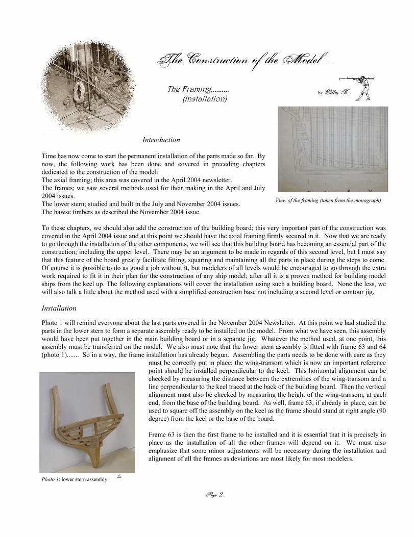
Photo 1 will remind everyone about the last parts covered in the November 2004 Newsletter. At this point we had studied theparts in the lower stern to form a separate assembly ready to be installed on the model. From what we have seen, this assemblywould have been put together in the main building board or in a separate jig. Whatever the method used, at one point, thisassembly must be transferred on the model. We also must note that the lower stern assembly is fitted with frame 63 and 64(photo 1)....... So in a way, the frame installation has already begun. Assembling the parts needs to be done with care as they
must be correctly put in place; the wing-transom which is now an important referencepoint should be installed perpendicular to the keel. This horizontal alignment can bechecked by measuring the distance between the extremities of the wing-transom and aline perpendicular to the keel traced at the back of the building board. Then the verticalalignment must also be checked by measuring the height of the wing-transom, at eachend, from the base of the building board. As well, frame 63, if already in place, can beused to square off the assembly on the keel as the frame should stand at right angle (90degree) from the keel or the base of the board.
Frame 63 is then the first frame to be installed and it is essential that it is precisely inplace as the installation of all the other frames will depend on it. We must alsoemphasize that some minor adjustments will be necessary during the installation andalignment of all the frames as deviations are most likely for most modelers.
Page 2
Photo 1: lower stern assembly.
View of the framing (taken from the monograph)
The Construction of the Model . . . .
The Framing.......... (Installation)
by Gilles K.

“We must note that such alignment differences are normal.Aim for perfection to obtain the best work possible .........”
Photo 2 shows the method used to insure that the frames are fitted vertically.As the rising-wood is notched, the foot of each frame is firmly seated, even ifthe notches seem quite small. As a result, all adjustments will have to takeplace at the top of the frames. Note that a preliminary fitting must be done forevery frame. Any adjustment should end up being minimal. The spacing at thetop of the frames should be the same as the one at the bottom and the crosstimber placed at the top (during the frame construction process) should beadjusted in consequence. Note that this cross timber has several functions; thespacing from frame to frame along the hull and the spacing between thetop-timbers of a given frame.
The horizontal alignment is checked by measuring the distance from the frameto the line traced across the back of the building board. This operation ensuresthe symmetry of the hull from side to side.This alignment is also achieved with all the lines traced across the upper levelof the building board. These lines, which were traced during the constructionof the building board show the location of each frame in the jig. In my casethese lines correspond to the aft face of each frame. If these lines are trulyperpendicular to the keel, the sides of the hull will be symmetrical.
All the frames are checked using the same method and, once again, both alignment, horizontal and vertical, are very important.
“Having decided to install the spacers located between the frames,we will look at this step right away, and come back to the installation
of the frames a little later .....”
Before we go any further into the installation of the frames, we mustlook at, and maybe consider working on the inclusion of other parts.I have personally decided to work on installing the spacers at thisstage of the construction. Some will say that this operation addssome degree of difficulty into the process, but by making a fewpreparations, it should not present too much of a problem. Theimportant factor is to make sure that they are lined up from frame toframe.
As indicated on the monograph, the framing of Le Gros Ventreincludes a number of spacers located between each frame. In total,we find 5 rows along the lower part of the hull. We must also notethat these spacers are an integral part of the framing as they add a lotof solidity to the assembly. In a way, they are indispensable. Thelocation of these 5 rows is as follow:1) One centre row. These spacers are installed vertically between the rising-wood and the keelson (refer to photo 4).2) A row of spacers is located atop the joint between the floor-timbers and the futtocks above on both sides of the hull (photo5a).3) This row is also installed on both sides of the hull. They are located atop the joint between the half floor-timber and thefuttocks above (photo 5b)Each spacer is worked to form a rounded channel to allow water drainage on the sides of the hull, between the outside plankingand the frames; the channel is on the outside face of the spacer for the water to move from top to bottom. As far as the centerrow, the channel is located at the foot of the spacer and runs across; above the rising-wood.
Photo 2:Checking the vertical fitting of the frames.
Photo 3: Horizontal alignment of th frames.
> <
> <
Page 3
Page 4
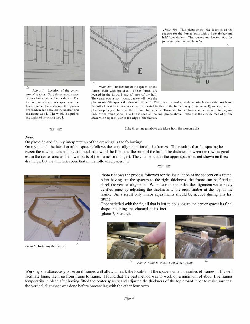
Photo 6 shows the process followed for the installation of the spacers on a frame.After having cut the spacers to the right thickness, the frame can be fitted tocheck the vertical alignment. We must remember that the alignment was alreadyverified once by adjusting the thickness to the cross-timber at the top of theframe. As a result only minor adjustments should be needed during this lastfitting.Once satisfied with the fit, all that is left to do is togive the center spacer its finalshape including the channel at its foot(photo 7, 8 and 9).
Working simultaneously on several frames will allow to mark the location of the spacers on a on a series of frames. This willfacilitate lining them up from frame to frame. I found that the best method was to work on a minimum of about five framestemporarily in place after having fitted the center spacers and adjusted the thickness of the top cross-timber to make sure thatthe vertical alignment was done before proceeding with the other four rows.
Note:On photo 5a and 5b, my interpretation of the drawings is the following:On my model, the location of the spacers follows the same alignment for all the frames. The result is that the spacing be-tween the row reduces as they are installed toward the front and the back of the hull. The distance between the rows is great-est in the center area as the lower parts of the frames are longest. The channel cut in the upper spacers is not shown on thesedrawings, but we will talk about that in the following pages…..
Photo 5a: The location of the spacers on theframes built with crotches. These frames arelocated in the forward and aft area of the hull.The center row is not shown, but we will note theplacement of the spacer the closest to the keel. This spacer is lined up with the joint between the crotch andthe futtock next to it. As far as the row located further up the frame (away from the keel), we see that it isplace atop the joint between the different frame parts. The center line of the spacer corresponds to the jointlines of the frame parts. The line is seen on the two photos above. Note that the outside face of all thespacers is perpendicular to the edge of the frames.
(The three images above are taken from the monograph)
Photo 5b: This photo shows the location of thespacers for the frames built with a floor-timber andhalf floor-timber. The spacers are located atop thejoints as described in photo 5a.
Photo 4: Location of the centerrow of spacers. Only the rounded shapeof the channel at the foot is shown. Thetop of the spacer corresponds to thelower face of the keelson… the spacersare sandwiched between the keelson andthe rising-wood. The width is equal tothe width of the rising wood.
> <
Photo 6: Installing the spacers
Photos 7 and 8: Making the center spacer.
> <

Working in this manner, the location of the other rows of spacers can beeasily marked. The next step consists of removing the first frame of thisgroup (photo 10), then install the four upper spacers, checking the verticalalignment of the frame and to glue it on the keel. At the same time, anotherframe is added to the group and the sequence is repeated; installation of thefour spacers, checking of the frame alignment, shaping and gluing of thecenter spacer, then gluing of the frame onto the keel, etc……..
Some modelers will choose not to proceed with the installation of thespacers at this time. Of course all of the frames can be put in placeand glued first. In this case, the spacers will be fitted and glued inplace after having removed the framed hull from the building board.The spacers can then be lined up following a batten placed along theoutside of the hull as per their location of the four rows on the plan.This method makes the installation somewhat easier as the batten canbe used as a guide. Here again, this is up to each modeler to choosethe working order, but at least this will show that there are differentalternatives.
“One thing is certain, and that is that it is preferable to work simul-taneously between the forward and aft frame.............. ”
As we have seen in the previous pages, the building board composedof two levels should make the installation of the frames somewhateasier as it allows working with good, constant reference points. Theupper level facilitates holding the frames in place while easing thealignment of the parts during assembly. Though we must also notethat depending on the height at which the upper level is place, someminor problems can occur, especially if the jig is cut in one piece. Ifthe jig is placed above the widest breadth of the hull, for examplefollowing the deck line, the installation becomes a little difficult asthe opening is too narrow for the frames to go thru.
As a result, it is important to proceed by temporarily fitting theframes in groups. Once they are fitted vertically, from group togroup, it is important to make sure that the last few frame are notglued in place before all the remaining frames have been aligned. Asthis is done, the checked location of the frames is marked onto theupper level (jig) just in case they do not correspond with the initiallines traced during the construction of the building board. Then onehalf of the jig can be lifted to allow the frames to go thru. If the jighas been made in one piece, it is at this point that it should be cutlongitudinally; in two.
Page 5
Photo 10: A number offrames are in place comple-mented by the spacers in be-tween. Several forwardframes are in the process of
being lined up with the center spacers and upper the cross-timbers temporarily in place.The alignment is checked using a square that is placed against the keel and the top of theframe. The square is then moved along the bottom and the top of the frame; if there iscontact along the entire edge of the frame, the frame is set vertical.
Photo 9: Fitting the spacer.
Photo 11: The frames and spacers are inplace. The extra length of the spacerswill be sanded off later.
> <
Page 6
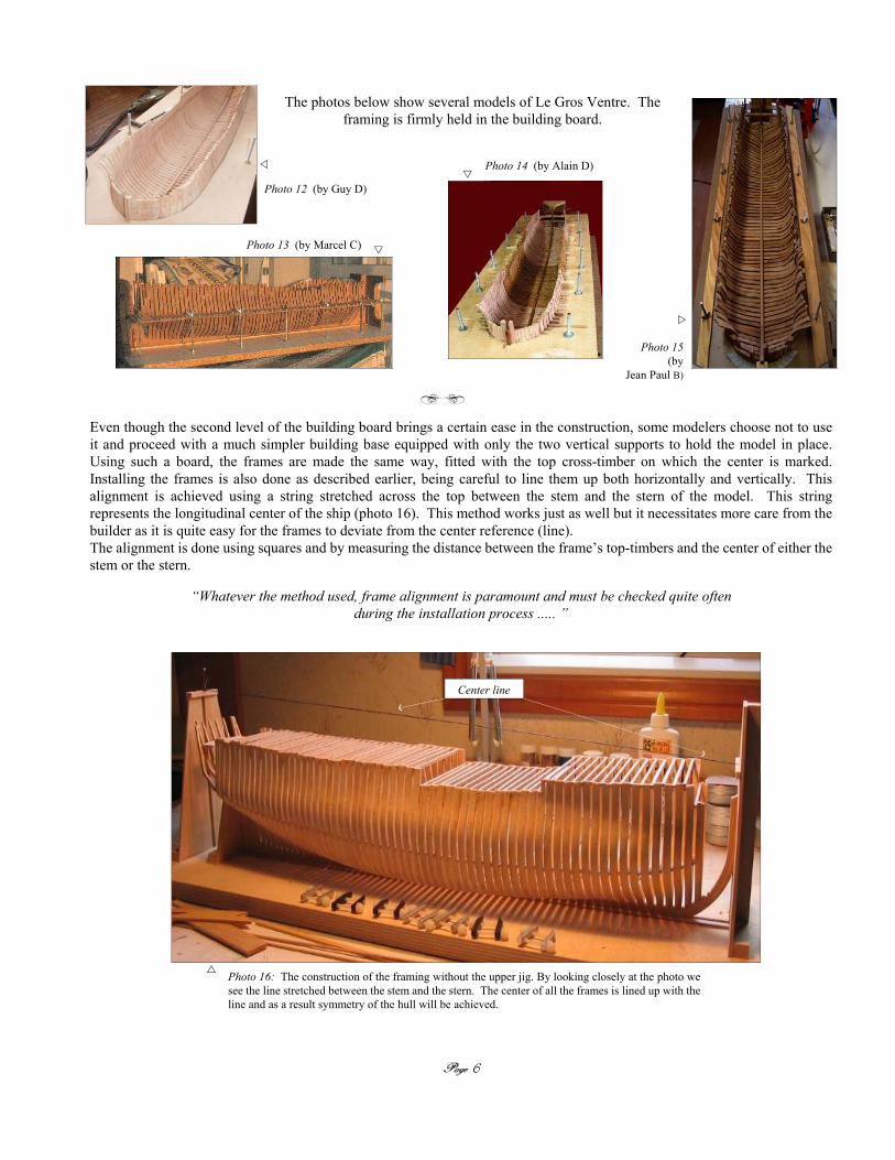
Photo 12 (by Guy D)
Even though the second level of the building board brings a certain ease in the construction, some modelers choose not to useit and proceed with a much simpler building base equipped with only the two vertical supports to hold the model in place.Using such a board, the frames are made the same way, fitted with the top cross-timber on which the center is marked.Installing the frames is also done as described earlier, being careful to line them up both horizontally and vertically. Thisalignment is achieved using a string stretched across the top between the stem and the stern of the model. This stringrepresents the longitudinal center of the ship (photo 16). This method works just as well but it necessitates more care from thebuilder as it is quite easy for the frames to deviate from the center reference (line).The alignment is done using squares and by measuring the distance between the frame’s top-timbers and the center of either thestem or the stern.
“Whatever the method used, frame alignment is paramount and must be checked quite oftenduring the installation process ..... ”
Photo 13 (by Marcel C)
Photo 15(by
Jean Paul B)
Photo 16: The construction of the framing without the upper jig. By looking closely at the photo wesee the line stretched between the stem and the stern. The center of all the frames is lined up with theline and as a result symmetry of the hull will be achieved.
> <
Photo 14 (by Alain D)
Center line
The photos below show several models of Le Gros Ventre. Theframing is firmly held in the building board.

Page 7
Preliminary sanding ……and other steps........... .
After having installed all the frames and once the glue has had time to dry,the last spacers are put in place. Then the outside of the framing is lightlysanded to obtain the bevels on the frames. As well the filling pieces locatedunder the lower transom are cut and placed. Then more sanding is done inpreparation for the wales to be added (later). As far as sanding, thisoperation is done using a rotary tools fitted with small home made sandingdisks. Final sanding will be done at a later stage with fine paper.
I am also adding photos showing the shape of the channels cut in the upper spacers (photos 19, 20 and 21). The channelis located on the outside face of the spacers to allow water to drain from the top to bottom of the hull between the plankingand the frame.
As was indicated in the preceding pages, simultaneously working on the forward and aft frames is recommended;essentially the installation of the hawse timbers and first couple of frames. The hawse timbers should be put in place quiteearly in the process. Photo 17 shows the installation at an advanced stage. The alignment of frame 1 can be accomplishedby measuring the distance separating it from the last installed frame, aft. Once this frame is in place, the hawse timbers arevery easily installed as they had already been fitted during fabrication
Photo 17: Most of the frames and the hawse timbersare in place. At this point the upper jig was cut in two toallow putting the frames in place. The installation of thelast frames was also done using a string stretched betweenthe stem and stern supports to add another reference in thecenter of the hull. This step must be done quite quickly topermit adjusting the set up once the jig is brought back toits original height. As well, at this point only the centerspacers are put in place as the last three frames are put inplace at the same time. The two halves of the jig are thensecured in place with a couple screws at the front and backin order to firmly hold the frames.
Photo 20:. The spacers are in place. The two located aft havebeen shaped; the rest will be done later ……..
Photo 18: The filling pieces are in place.
Photo 19: This image was taken fromthe work of Jean Boudriot (the 74 GunShip) and shows the shape of the channelon the spacers (b and c on the photo).
> <
Photo 21: Shaping the channel(photo by Jean Paul B.)
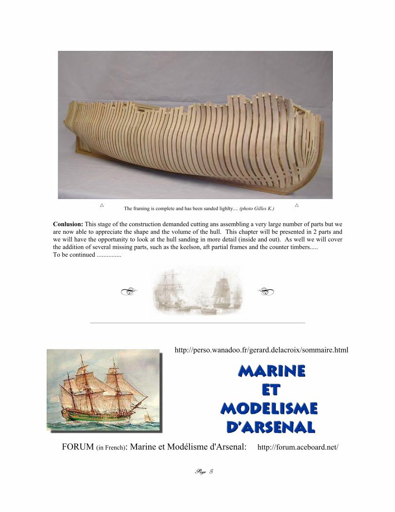
The framing is complete and has been sanded lighlty.... (photo Gilles K.)
> <
http://perso.wanadoo.fr/gerard.delacroix/sommaire.html
FORUM (in French): Marine et Modélisme d'Arsenal: http://forum.aceboard.net/
Page 8
Conlusion: This stage of the construction demanded cutting ans assembling a very large number of parts but weare now able to appreciate the shape and the volume of the hull. This chapter will be presented in 2 parts andwe will have the opportunity to look at the hull sanding in more detail (inside and out). As well we will coverthe addition of several missing parts, such as the keelson, aft partial frames and the counter timbers.....To be continued ...............

Page 9
PIER BOOKS Inc. / DUPONT COMMUNICATIONSExclusive Distributor in North America (except Quebec) for
Les Éditions Ancre
http://www.tco.com/pierbooks/PO Box #5, PIERMONT N.Y.
10968 - 0005 USATel (845) 268 5845 - Fax (845) 268 8804
Email: [email protected]
- The cover of the monograph -
> <
Jean BOUDRIOT & Hubert BERTIpresent
LA COLLECTIONARCHÉOLOGIE NAVALE FRANÇAISE
A library of 48 works in 59 volumes on thefrench Sailing Navy from 1650 à 1900.
More than 5000 drwaings from Jean Boudriot.More than 3000 model photos .
More than 4000 scketches, plates, drawings andreproductions of period documents.
C/O Hubert BERTI75 Avenue George V
06000 NICE - FRANCEFax : 33.(0)4.93.53.47.49 http://www.ancre.fr
− Where to get the Monograph in North America −
− Where to get the Monograph in Europe and the rest of the world −
− Technical Support Team ( Cont . . . . .) − Bill Short
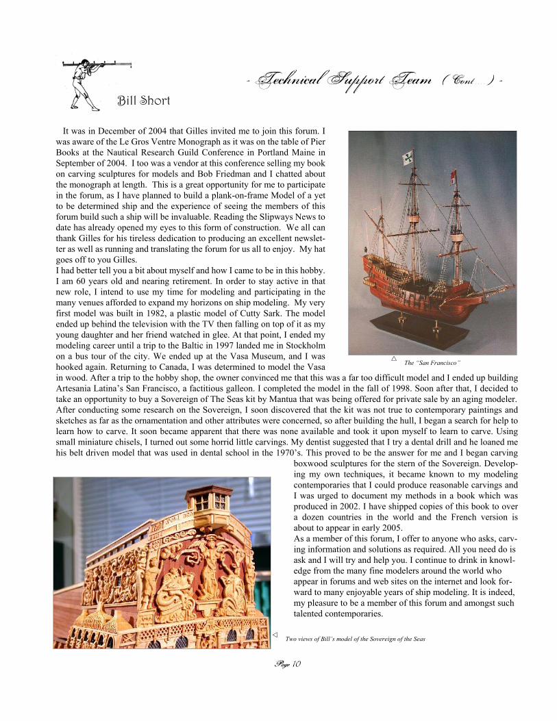
It was in December of 2004 that Gilles invited me to join this forum. Iwas aware of the Le Gros Ventre Monograph as it was on the table of PierBooks at the Nautical Research Guild Conference in Portland Maine inSeptember of 2004. I too was a vendor at this conference selling my bookon carving sculptures for models and Bob Friedman and I chatted aboutthe monograph at length. This is a great opportunity for me to participatein the forum, as I have planned to build a plank-on-frame Model of a yetto be determined ship and the experience of seeing the members of thisforum build such a ship will be invaluable. Reading the Slipways News todate has already opened my eyes to this form of construction. We all canthank Gilles for his tireless dedication to producing an excellent newslet-ter as well as running and translating the forum for us all to enjoy. My hatgoes off to you Gilles.I had better tell you a bit about myself and how I came to be in this hobby.I am 60 years old and nearing retirement. In order to stay active in thatnew role, I intend to use my time for modeling and participating in themany venues afforded to expand my horizons on ship modeling. My veryfirst model was built in 1982, a plastic model of Cutty Sark. The modelended up behind the television with the TV then falling on top of it as myyoung daughter and her friend watched in glee. At that point, I ended mymodeling career until a trip to the Baltic in 1997 landed me in Stockholmon a bus tour of the city. We ended up at the Vasa Museum, and I washooked again. Returning to Canada, I was determined to model the Vasain wood. After a trip to the hobby shop, the owner convinced me that this was a far too difficult model and I ended up buildingArtesania Latina’s San Francisco, a factitious galleon. I completed the model in the fall of 1998. Soon after that, I decided totake an opportunity to buy a Sovereign of The Seas kit by Mantua that was being offered for private sale by an aging modeler.After conducting some research on the Sovereign, I soon discovered that the kit was not true to contemporary paintings andsketches as far as the ornamentation and other attributes were concerned, so after building the hull, I began a search for help tolearn how to carve. It soon became apparent that there was none available and took it upon myself to learn to carve. Usingsmall miniature chisels, I turned out some horrid little carvings. My dentist suggested that I try a dental drill and he loaned mehis belt driven model that was used in dental school in the 1970’s. This proved to be the answer for me and I began carving
boxwood sculptures for the stern of the Sovereign. Develop-ing my own techniques, it became known to my modelingcontemporaries that I could produce reasonable carvings andI was urged to document my methods in a book which wasproduced in 2002. I have shipped copies of this book to overa dozen countries in the world and the French version isabout to appear in early 2005.As a member of this forum, I offer to anyone who asks, carv-ing information and solutions as required. All you need do isask and I will try and help you. I continue to drink in knowl-edge from the many fine modelers around the world whoappear in forums and web sites on the internet and look for-ward to many enjoyable years of ship modeling. It is indeed,my pleasure to be a member of this forum and amongst suchtalented contemporaries.
The “San Francisco”
Two views of Bill’s model of the Sovereign of the Seas
Page 10

- A few more views of Bill’s Sovereign -
Page 11
> <

Rotary Power Carving TechniquesBy Bill Short
Carving Ornamentation for Ship ModelsRotary Power Carving Techniques
Bill Short
The layout of the booklet is as follows:
Table of ContentsIntroduction
Chapter 1 The tools available to rotary carveChapter 2 Wood selection for carving ornamentation
Chapter 3 VisualizationChapter 4` How to rotary carve
Chapter 5 Carving complex shapesChapter 6 Finishing the carvingChapter 7 Safety Considerations
BibliographyIndex
> <
It is a spiral bound booklet with an acetate cover, stiff board back, full colour cover page and the rest of the 52 pages are printed inblack and white with high quality photos on 70# Hammermill paper. It will lay flat on your bench and can be folded over on itselfto a one page size.
The booklet, which covers in detail, carving with rotary tools and dental burrs, is available for immediate shipment. It is 52 pagesand has over 50 high definition digital photographs detailing the step-by-step carving lessons in both bas-relief and carving-in-the-round.
Additionally, I have added a bibliography of very good reference books on ornementation and covered the methods of carvingseveral of the complex carvings found on my model of The Sovereign of The Seas.
> <
The selling price of the booklet including air mail postage and handling is:
Destinations in the USA and Canada $25.00 US Funds Destinations in the UK and overseas: $30.00 US Funds
Payment must be in the form of a US Money Order or International money order in US dollars. As I am not a business, my bank cannot
handle personal checks in other currencies, or other forms of payment. As you already know, it is not advisable to send cash in the
mail for obvious reasons.
Mail your payment at your earliest convenience to:
Bill Short3 Karsam Court, SS1,
Niagara-on-the-Lake, OntarioL0S 1J0 Canada
Email:
> <
Page 12
−The Slipway News. . . . . . Le GROS VENTRE −
Volume 2 - Issue 1 - March 2005
The Contributors ........Text and photos by: Bill S. & Gilles K.
Photos by: Marc M. - Bill S. - Jean Paul B. - Marcel C. - Guy D. - Alain D.
Thank you. ..........
Le Gros Ventre Project - Gilles Korent & Gérard Delacroix - © 2005
> <
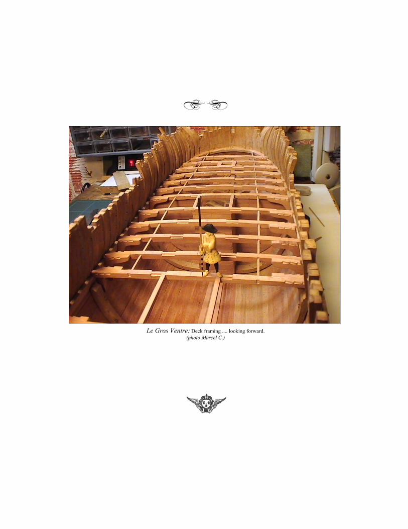
Le Gros Ventre: Deck framing .... looking forward.(photo Marcel C.)
> <