ShipRight Design and construction - Lloyd's Register and Construction/Ship...ShipRight Design and...
16
ShipRight Design and construction Procedure for Ship Units July 2014 Appendix A Strength assessment
Transcript of ShipRight Design and construction - Lloyd's Register and Construction/Ship...ShipRight Design and...

ShipRight Design and construction
Procedure for Ship Units
July 2014
Appendix A Strength assessment


ShipRight Procedure for Ship Units, July 2014 - Appendix A
Lloyd’s Register
CONTENTS
Contents STRENGTH ASSESSMENT 1Section A1 Strength Assessment 1 A1.1 General 1 A1.2 Cargo Tank Structural Strength Analysis 3 A1.3 Local Fine Mesh Structural Strength Analysis 7 A1.4 Application of Scantlings in Cargo Tank Region 9

Lloyd’s Register
ShipRight Procedure for Ship Units, July 2014 - Appendix A
2

ShipRight Procedure for Ship Units, July 2014 - Appendix A
Lloyd’s Register
SECTION A1
Strength Assessment
Section A1: Strength Assessment
■ Section A1: Strength Assessment
A1.1 General
A1.1.1 ApplicationA1.1.1.1 A strength assessment of the hull structure using finite element analysis is mandatory.
A1.1.1.2 The finite element analysis consists of two parts:• cargo tank analysis to assess the strength of longitudinal
hull girder structural members, primary supporting structural members and transverse bulkheads.
• fine mesh analysis to assess detailed stress levels in local structural details.
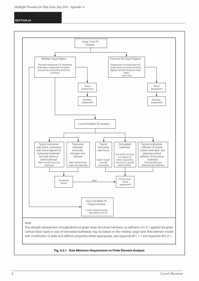
A1.1.1.3 A flow diagram showing the minimum requirement of finite element analysis is shown in Figure A.2.1.
A1.1.1.4 The structural assessment is to be carried out in accordance with the requirements given in Appendix B. The structural assessment is to verify that the acceptance criteria specified in A1.2.5 and A1.3.5 are complied with.
A1.1.1.5 The application of the scantlings verified by the structural assessment within the cargo tank region is to be in accordance with A1.4.
1
Lloyd’s Register
ShipRight Procedure for Ship Units, July 2014 - Appendix A
Fig. A.2.1 Rule Minimum Requirement on Finite Element Analysis
SECTION A1
Midship Cargo Region
Strength assessment of transversebulkheads, longitudinal hull girderand primary supporting structural
members
Fore and Aft Cargo Regions
Assessment of longitudinal hullgirder shear structural membersagainst vertical hull girder shear
loads(see note)
Stressassessment
Bucklingassessment
Stressassessment
Bucklingassessment
Local Fine Mesh FE Analysis
Transversebulkheadhorizontal
stringers andbuttress
Main bracket toes,heels and openings
Very Fine Mesh FEFatigue Analysis
Lower hopper knuckle(see Section 9/3.3)
Typicaltransverseweb frame
Upper hopperknuckle
connection
Corrugatedbulkhead
Connection of lowercorrugation to
below supportingstructure or gusset
plate (if fitted)
FE fine meshstress
assessment
Screeningcriteria
Cargo Tank FEAnalysis
Typical transverseweb frame, transverseweb frame adjacent totransverse bulkhead
and web frame ofwash bulkhead
Main bracket toes andopenings
Typical longitudinalstiffeners of double
bottom and deck, andadjoining vertical
stiffener of transversebulkhead
End brackets andattached web stiffeners
(fail)
NoteThe strength assessment of longitudinal hull girder shear structural members, as defined in A1.2.1 against hull girder vertical shear loads in way of transverse bulkheads may be based on the midship cargo tank finite element model with modification of plate and stiffener properties where appropriate, see Appendix B/1.1.1 and Appendix B/2.2.1.
2
ShipRight Procedure for Ship Units, July 2014 - Appendix A
Lloyd’s Register
SECTION A1
A1.1.2 Submission of resultsA1.1.2.1 A detailed report of the structural analysis is to be submitted to demonstrate compliance with the specified structural design criteria. This report shall include the following information:(a) list of plans used including dates and versions(b) detailed description of structural modelling including all
modelling assumptions and any deviations in geometry and arrangement of structure compared with plans
(c) plots to demonstrate correct structural modelling and assigned properties
(d) details of material properties, plate thickness, beam properties used in the model
(e) details of boundary conditions(f) details of all loading conditions reviewed with calculated hull
girder shear force and bending moment distributions(g) details of applied loads and confirmation that individual and
total applied loads are correct(h) plots and results that demonstrate the correct behaviour of
the structural model under the applied loads(i) summaries and plots of global and local deflections(j) summaries and sufficient plots of stresses to demonstrate
that the design criteria are not exceeded in any member(k) plate and stiffened panel buckling analysis and results(l) tabulated results showing compliance, or otherwise, with the
design criteria(m) proposed amendments to structure where necessary,
including revised assessment of stresses, buckling and fatigue properties showing compliance with design criteria.
A1.1.3 Computer programsA1.1.3.1 In general, any finite element computation program recognised by LR may be employed to determine the stress and deflection of the hull structure, provided that the combined effects of bending, shear, axial and torsional deformations are considered.
A1.1.3.2 The computer program used for the assessment of panel buckling capability is to take account of the combined interaction of bi-axial compressive stresses, shear stress and lateral pressure loads.
A1.1.3.3 A computer program that has been demonstrated to produce reliable results to the satisfaction of LR is regarded as a recognised program. Where the computer programs employed are not supplied or recognised by LR, full particulars of the computer program, including calculation output, are to be submitted for approval. It is recommended that the designers consult LR on the suitability of the computer programs intended to be used prior to the commencement of any analysis work.
A1.2 Cargo Tank Structural Strength Analysis
A1.2.1 Objective and scopeA1.2.1.1 The analysis is to cover at least the assessment of:(a) longitudinal hull girder structural members, primary
supporting structural members and transverse bulkheads in the midship cargo tank region, and
(b) longitudinal hull girder shear structural members in way of transverse bulkheads against hull girder vertical shear loads within the cargo area. These structural members include side shell, inner hull longitudinal bulkheads including upper sloped plate where fitted, hopper, longitudinal bulkheads and double bottom girders. The required strengthening in way of transverse bulkheads for hull girder shear loads in the forward, midship or aft cargo region may be based on the maximum hull girder shear force within the region considered. Alternatively assessment may be carried out to determine the strengthening requirement in way of individual transverse bulkhead position. The details are given in Appendix B/1.1.1.
A1.2.1.2 The required strengthening in way of transverse bulkheads for hull girder shear loads in the forward, midship or aft cargo region may be based on the maximum hull girder shear force within the region considered. Alternatively assessment may be carried out to determine the strengthening requirement in way of individual transverse bulkhead position. The details are given in Appendix B/1.1.1.
A1.2.1.3 The analysis is to verify that the following are within the acceptance criteria under the applied static and dynamic loads:(a) stress level in the plating of longitudinal hull girder structural
members, primary support structural members and transverse bulkheads, face plate of primary support members modelled by plate or rod elements.
(b) buckling capability of plates and stiffened panels.
A1.2.2 Structural modellingA1.2.2.1 The modelling scantlings of the cargo tank finite element model are to be based on net scantlings as described in Section 2.6 of the ShipRight Procedure for Ship Units and Appendix B/2.2.1.5.
A1.2.2.2 The length of the cargo tank finite element model is to cover three cargo tank lengths. Where the tanks in the midship cargo region are of different lengths, the middle tank of the finite element model is to represent the cargo tank of the greatest length. All main longitudinal and transverse structural elements are to be represented in the finite element model. These include inner and outer shell, double bottom floor and girder system, transverse and vertical web frames, stringers, transverse and longitudinal bulkhead structures. All plating and stiffeners, including web stiffeners, on these structural elements are to be modelled.
3

Lloyd’s Register
ShipRight Procedure for Ship Units, July 2014 - Appendix A
SECTION A1
A1.2.2.3 The mesh of the finite element model is to follow the stiffening system of the structure as far as practical, and is to represent the actual plate panels between stiffeners.
A1.2.2.4 The structure modelling is to be in accordance with the requirements given in Appendix B/2.2.
A1.2.3 Loads and loading conditionsA1.2.3.1 The combinations of the ship static and dynamic loads which are likely to impose the most onerous load regimes on the hull structure are to be investigated in the structural analysis.
A1.2.3.2 The standard load cases to be used in the structural analysis are given in Appendix B/2.3.1, see also Chapter 5 of the ShipRight Procedure for Ship Units. These load cases cover static + dynamic design load combinations and static tank testing conditions. The standard load cases are to be used for newbuilds but are not mandatory for conversions/redeployments.
A1.2.3.3 Where the loading conditions specified by the owner are not covered by the standard load cases then these additional loading conditions are to be examined, see also Chapter 5 of the ShipRight Procedure for Ship Units and Appendix B/2.3.1.
A1.2.4 Load applications and boundary conditionsA1.2.4.1 All simultaneously acting hull girder and local loads are to be applied to the model. The application of local and hull girder loads to the finite element model is to be in accordance with the requirement given in Appendix B/2.4 and B/2.5.
A1.2.4.2 The boundary conditions to be applied are given in Appendix B/2.6.
A1.2.5 Acceptance criteriaA1.2.5.1 Verification of results against the acceptance criteria is to be carried out in accordance with Appendix B/2.7.
A1.2.5.2 Verification of results against the acceptance criteria is to be carried out for all structural members within the longitudinal extent of the middle tanks of the three tank FE model, and the regions forward and aft of the middle tanks up to the extent of the transverse bulkhead stringer and buttress structure. For the assessment of shear strength in way of transverse bulkheads against hull girder shear loads, stress level and buckling capability of inner hull longitudinal bulkheads including upper sloped plate where fitted, side shell, longitudinal bulkheads, hopper and bottom longitudinal girders are to be verified against the acceptance criteria. See also Appendix B/2.7.1.
A1.2.5.3 The structural analysis is to demonstrate that the permissible von Mises stress criteria and utilisation factor against buckling for plate and stiffened panels specified in Tables A.2.1 and A.2.2 are not exceeded.
A1.2.5.4 Capacity models used for the assessment of local buckling capability of plate and stiffened panels are to be based on deduction of full corrosion addition thickness from the plate and stiffeners, as described in Section 2.6 of the ShipRight Procedure for Ship Units and Appendix B/2.7.3.
A1.2.5.5 Where a lower stool is not fitted to a transverse or longitudinal corrugated bulkhead, the maximum permissible stresses and buckling utilisation factors given in Tables A.2.1 and A2.2 are to be reduced by 10% for the corrugation and below supporting structure within the extent defined as follows:(a) Full height of the corrugation(b) Supporting structure for a transverse corrugated bulkhead - longitudinally within half a web frame space forward and aft
of the bulkhead(c) Supporting structure for a longitudinal corrugated bulkhead –
transversely within three longitudinal stiffener spacings from each side of the bulkhead.
A1.2.5.6 Refer to Pt 10, Ch 1,3.1.3 of the Rules for Offshore Units regarding through thickness stresses.
4

ShipRight Procedure for Ship Units, July 2014 - Appendix A
Lloyd’s Register
SECTION A1
Table A.2.1 Maximum Permissible Stresses
Structural component Yield utilisation factor
Internal structure in tanks
Plating of all non-tight structural members including transverse web frame structure, wash bulkheads, internal web, horizontal stringers, floors and girders. Face plate of primary support members modelled using plate or rod elements
λy ≤ 1.0 (load combination S + D)
λy ≤ 0.8 (load combination S)
Structure on tank boundaries
Plating of deck, sides, inner sides, hopper plate, bilge plate, plane and corrugated cargo tank longitudinal bulkheads. Tight floors, girders and webs
λy ≤ 0.9 (load combination S + D)
λy ≤ 0.72 (load combination S)
Plating of inner bottom, bottom, plane transverse bulkheads and corrugated bulkheads.
λy ≤ 0.8 (load combination S + D)
λy ≤ 0.64 (load combination S)
Where:λy yield utilisation factor
for plate elements in general
for rod elements in general
σvm von Mises stress calculated based on membrane stresses at element’s centroid, in N/mm2
σrod axial stress in rod element, in N/mm2
σyd specified minimum yield stress of the material, in N/mm2, but not to be taken as greater than 315 N/mm2 for load combination S + D in areas of stress concentration (2)
Notes1. Structural items given in the table are for guidance only. Stresses for all parts of the FE model specified in A1.2.5.2 are to be verified
against the permissible stress criteria. See also Appendix B/2.7.1.2. Areas of stress concentration are corners of openings, knuckle joints, toes and heels of primary supporting structural members and
stiffeners.3. Where a lower stool is not fitted to a transverse or longitudinal corrugated bulkhead, the maximum permissible stresses are to be
reduced by 10% in accordance with A1.2.5.5.
=
=
5

Lloyd’s Register
ShipRight Procedure for Ship Units, July 2014 - Appendix A
Table A.2.2 Maximum Permissible Utilisation Factor Against Buckling
Structural component Buckling utilisation factor
Plate and stiffened panels (3) η ≤ 1.0 (load combination S + D)
η ≤ 0.8 (load combination S)
Web plate in way of openings η ≤ 1.0 (load combination S + D)
η ≤ 0.8 (load combination S)
Pillar buckling of cross tie structure η ≤ 0.75 (load combination S + D)
η ≤ 0.65 (load combination S)
Corrugated bulkheadsflange bucklingcolumn buckling
η ≤ 0.9 (load combination S + D)
η ≤ 0.72 (load combination S)
Where:η utilisation factor against buckling calculated in accordance with Appendix B/2.7.3.
Notes1. Buckling capability of curved panels (e.g. bilge plate), face plate and tripping bracket of primary supporting members are not
assessed based on finite element stress result2. Where a lower stool is not fitted to a transverse or longitudinal corrugated bulkhead, the maximum permissible buckling utilisation
factors are to be reduced by 10% in accordance with A1.2.5.5
SECTION A1
6

ShipRight Procedure for Ship Units, July 2014 - Appendix A
Lloyd’s Register
A1.3 Local Fine Mesh Structural Strength Analysis
A1.3.1 Objective and scopeA1.3.1.1 For tankers of conventional arrangements, as a minimum requirement, the following areas in the midship cargo region are to be investigated: (a) main bracket toes and openings at critical locations and upper
hopper knuckle joint of a typical transverse web frame located in the midship tank. Where a wash bulkhead is fitted, main bracket toes and openings at critical locations of transverse and vertical webs
(b) main bracket toes and openings at critical locations on a typical transverse web frame adjacent to a transverse bulkhead in way of the transverse bulkhead horizontal stringers
(c) main bracket toes, heels and openings at critical locations of horizontal stringers, connection of transverse bulkhead to double bottom girder or buttress of a typical transverse bulkhead
(d) connections of transverse and longitudinal corrugated bulkheads to bottom stool or inner bottom and double bottom supporting structure if a lower stool is not fitted. If a gusset plate is fitted the connection between the corrugation and the upper corners of the gusset are to be assessed
(e) end brackets and attached web stiffeners of typical longitudinal stiffeners of double bottom and deck, and adjoining vertical stiffener of transverse bulkhead.
A1.3.1.2 The selection of critical locations on the structural members described in A1.3.1.1 to perform fine mesh analysis is to be in accordance with Appendix B/3.1.
A1.3.1.3 Where the stress level in areas of stress concentration on structural members not specified in A1.3.1.1 exceeds the acceptance criteria of the cargo tank analysis, a fine mesh analysis is to be carried out to demonstrate satisfactory scantlings.
A1.3.1.4 Where the geometry can not be adequately represented in the cargo tank finite element model, a fine mesh analysis may be used to demonstrate satisfactory scantlings. In such cases the average stress within an area equivalent to that specified in the cargo tank analysis (typically s by s) is to comply with the requirement given in Table A.2.1. See also Note 1 of Table A.2.3.
A1.3.2 Structural modellingA1.3.2.1 The fine mesh structural models are to be in accordance with the requirements given in Appendix B/3.2.
A1.3.2.2 The fine mesh analysis may be carried out by means of a separate local finite element model with fine mesh zones, in conjunction with the boundary conditions obtained from the cargo tank model, or by incorporating fine mesh zones into the cargo tank model.
A1.3.2.3 The extent of the local finite element models is to be such that the calculated stresses at the areas of interest are not significantly affected by the imposed boundary conditions and application of loads. Detailed requirements on the extension of local finite element models are given in Appendix B/3.2.
A1.3.2.4 The fine mesh zone is to represent the localised area of high stress. The finite element mesh size within the fine mesh zones is to be not greater than 50mm x 50mm. The extent of the fine mesh zone is to be in accordance with Appendix B/3.2.
A1.3.2.5 The fine mesh models are to be based on the net scantlings in accordance with Section 2.6 of the ShipRight Procedure for Ship Units and Appendix B/3.2.
A1.3.3 Loads and loading conditionsA1.3.3.1 The fine mesh detailed stress analysis is to be carried out for all the load cases, see A1.2.3.
A1.3.4 Load applications and boundary conditionsA1.3.4.1 The application of loads and boundary conditions to the finite element model is to be in accordance with the requirements given in Appendix B/3.4.
A1.3.5 Acceptance criteriaA1.3.5.1 Verification of stress results against the acceptance criteria is to be carried out in accordance with Appendix B/3.5.
A1.3.5.2 The structural assessment is to demonstrate that the von Mises stresses obtained from the fine mesh finite element analysis do not exceed the maximum permissible stress criteria specified in Table A.2.3.
A1.3.5.3 Refer to Pt 10, Ch 1,3.1.3 of the Rules for Offshore Units regarding through thickness stresses.
SECTION A1
7

Lloyd’s Register
ShipRight Procedure for Ship Units, July 2014 - Appendix A
Table A.2.3 Maximum Permissible Membrane Stresses for Fine Mesh Analysis
Element stress Yield utilisation factor
Element not adjacent to weld λy ≤ 1.7 (load combination S + D)
λy ≤ 1.36 (load combination S)
Element adjacent to weld λy ≤ 1.5 (load combination S + D)
λy ≤ 1.2 (load combination S)
Where:λy yield utilisation factor
for plate element for rod or beam element
λvm von Mises stress calculated based on membrane stress at element’s centroid, in N/mm2
λrod axial stress in rod element, in N/mm2
K higher strength steel factor, as defined in Pt 10, Ch 1,3.1 of the Rules for Offshore Units but not to be taken as less than 0.78 for load combination S + D
Notes1. Where the von Mises stress of the elements in the cargo tank FE model in way of the area under investigation by fine mesh
exceeds its permissible value specified in Table A.2.1, average von Mises stress, obtained from the fine mesh analysis, calculated over an area equivalent to the mesh size of the cargo tank finite element model is to be less than the permissible value specified in Table A.2.1
2. The maximum permissible stresses are based on the mesh size of 50mm x 50mm. Where a smaller mesh size is used, an average von Mises stress calculated in accordance with Appendix B/3.5.1 over an area equal to the specified mesh size may be used to compare with the permissible stresses.
3. Average von Mises stress is to be calculated based on weighted average against element areas:
where σvm-av is the average von Mises stress σvm-i is the von Mises stress of the ith plate element within the area considered Ai is the area of the ith plate element within the area considered n is the number of elements within the area considered4. Stress averaging is not to be carried across structural discontinuities and abutting structure5. Where a lower stool is not fitted to a transverse or longitudinal corrugated bulkhead, the maximum permissible stresses are to be
reduced by 10% for the areas under investigation by fine mesh analysis.
235=
235=
SECTION A1
n
1
Ai
n
1
8
ShipRight Procedure for Ship Units, July 2014 - Appendix A
Lloyd’s Register
A1.4 Application of Scantlings in Cargo Tank Region
A1.4.1 GeneralA1.4.1.1 The application of the scantlings that comply with the requirements of the finite element strength assessment, to the structure within the cargo tank region, is to be in accordance with the requirements given in this sub-section unless additional analysis demonstrates this to be unnecessary.
A1.4.1.2 The application given in this sub-section assumes that the same material yield strength of the structure is maintained throughout the cargo tank region. Where steel having a different yield strength is applied, the required scantlings are to be assessed.
A1.4.1.3 The scaling procedure given in this sub-section is based on scantlings that satisfied the requirements given in Section 2 and Appendix B. The scaling procedure is not applicable to cases where there are significant changes in the hull structure (e.g. internal turret) and/or the loads acting on the structure (e.g. topsides module loads) which should be subject to additional analysis.
A1.4.1.4 The net thickness and sectional properties for plating and local support members described in this sub-section are to be based on deduction of full corrosion addition, as specified in Section 2.6 of the ShipRight Procedure for Ship Units, from the gross scantlings. The gross thickness of plating, web and face plate of local support members are to be obtained by adding the full corrosion addition to the net thickness.
A1.4.2 Application of scantlings to deckA1.4.2.1 The scantlings of deck plating and deck longitudinal stiffeners are to be maintained longitudinally within 0.4Lamidships. The scantlings of deck plating and deck longitudinal stiffeners at a given transverse location within 0.4L amidships are not to be taken as less than the maximum of that required for the corresponding transverse location along the length of the middle tanks of the cargo tank finite element model required by Appendix B/1.1.1.5.
A1.4.2.2 Outside 0.4L amidships, the scantlings of the deck plating and deck longitudinal stiffeners may be tapered to that required by Pt 10, Ch 3 of the Rules for Offshore Units at the ends of the cargo tank region.
A1.4.3 Application of scantlings to inner bottomA1.4.3.1 The thickness of inner bottom plating may vary along the length and breadth of a tank.
A1.4.3.2 The scantlings of the inner bottom plating and longitudinal stiffeners of midship cargo tanks are not to be less than that required for the corresponding location of the
middle tanks of the cargo tank finite element model required by Appendix B/1.1.1.5. These scantlings are to be maintained for all tanks within the cargo region, other than the fore-most and aft-most cargo tanks.
A1.4.3.3 For the fore-most and aft-most cargo tanks, the scantlings of the inner bottom longitudinal stiffeners are not to be less than the scantling requirements for the midship cargo tanks provided that the spacing of primary support members are not reduced in the forward and/or aft cargo tank. The minimum net thickness of the inner bottom plate, tib-net, is given by:
where:tib-net-mid required net thickness of the inner bottom plating for
the corresponding location in the midship tank, in mm lbdg effective bending span, of floor at location under
consideration, in accordance with Figure A.2.7, in mlbdg-mid effective bending span, of floor at corresponding
location in midship tank, defined in accordance with Figure A.2.7, in m
sib spacing between longitudinal stiffeners at location under consideration, in mm
sib-mid spacing between longitudinal stiffeners at corresponding location in midship tank, in mm
A1.4.4 Application of scantlings to bottomA1.4.4.1 The scantlings of bottom longitudinal stiffeners are to be maintained longitudinally within 0.4L amidships. The scantlings of the bottom longitudinal stiffener at a given transverse location within 0.4L amidships are not to be less than the maximum of that required for the corresponding transverse location along the length of the middle tanks of the cargo tank finite element model required by Appendix B/1.1.1.5.
A1.4.4.2 Outside 0.4L amidships, the scantlings of the bottom longitudinal stiffeners may be tapered to that required by Pt 10, Ch 3 of the Rules for Offshore Units at the ends of the cargo region.
A1.4.4.3 The thickness of the bottom plating may vary along the length and breadth of a tank. The bottom plate thicknesses of midship tanks are not to be less than that required for the corresponding location of the middle tanks of the cargo tank finite element model required by Appendix B/1.1.1.5. These thicknesses are to be maintained for all tanks within the cargo region, other than the fore-most and aft-most cargo tanks.
A1.4.4.4 For the fore-most and aft-most cargo tanks, the required minimum net thickness of the bottom plating, tbtm-net, is
tib-net=tib-net-midlbdg
0.25
mmlbdg-mid
ib
ib-mid
SECTION A1
S
S
9
Lloyd’s Register
ShipRight Procedure for Ship Units, July 2014 - Appendix A
to be obtained as follows:
where:tbtm-net-mid required net thickness of the bottom plating for the
corresponding location in the midship tank, in mmlbdg effective bending span, of floor at location under
consideration, in accordance with Figure A.2.7, in mlbdg-mid effective bending span, of floor at corresponding
location in midship tank, defined in accordance with Figure A.2.7, in m
sbtm spacing between longitudinal stiffeners at location under consideration, in mm
sbtm-mid spacing between longitudinal stiffeners at corresponding location in midship tank, in mm
A1.4.5 Application of scantlings to side shell, longitudinal bulkheads and inner hull longitudinal bulkheadsA1.4.5.1 The scantlings of plating and longitudinal stiffeners of side shell, longitudinal bulkheads and inner longitudinal bulkheads within 0.15D from the deck are to be maintained longitudinally within 0.4L amidships. The scantlings of plating and longitudinal stiffener at a given height are not to be less than the maximum of that required for the corresponding vertical location along the length of the middle tanks of the cargo tank finite element model required by Appendix B/1.1.1.5. Outside 0.4L amidships, the scantlings of the plating and stiffeners within 0.15D from the deck may be tapered to that required by Section 8 at the ends of the cargo tank region.
A1.4.5.2 The plate thickness of side shell, longitudinal bulkheads and inner hull longitudinal bulkheads, including hopper plating, outside 0.15D from the deck may vary along the length and height of a tank. The plate thickness away from the transverse bulkheads is not to be less than that required for the corresponding location of the middle tanks of the cargo tank finite element model required by Appendix B/1.1.1.5. These scantlings are to be maintained for all tanks within the cargo region, other than the fore-most and aft-most cargo tanks. For the fore-most and aft-most cargo tanks, the minimum net thickness of the side shell, longitudinal bulkheads or inner hull longitudinal bulkheads (including hopper plating) plating outside 0.15D from the deck is given by:
Where:tnet-mid required net thickness for corresponding location in
the midship tank, in mms spacing between longitudinal stiffeners at location
under consideration, in mmsmid spacing between longitudinal stiffeners at
corresponding location in midship tank, in mm
A1.4.5.3 The plate thickness of side shell, longitudinal bulkheads and inner hull longitudinal bulkheads, including hopper plating, in way of transverse bulkheads required for strengthening against hull girder shear loads is not to be less than that required by Appendix B/1.1.1.6, B/1.1.1.7 and B/1.1.1.8. Within 0.15D from the deck, the plate thicknesses in way of transverse bulkheads are not to be taken as less than that required by 1.4.5.1. Outside 0.15D from the deck, the plate thicknesses in way of transverse bulkheads are not to be taken as less than that required by A1.4.5.2.
A1.4.5.4 The scantlings of longitudinal stiffeners of side shell, longitudinal bulkheads, inner longitudinal bulkheads and hopper plate at a given height, outside 0.15D from the deck, are not to be less than that required for the corresponding vertical location of the middle tanks of the cargo tank finite element model as required by Appendix B/1.1.1.5. These scantlings are to be maintained for all tanks within the cargo region.
A1.4.6 Application of scantlings to transverse bulkheadsA1.4.6.1 The scantlings of transverse bulkhead plating, stiffeners and horizontal stringers may vary along the height and breadth of the bulkhead. The scantlings at a given location are not to be less than the maximum required at the corresponding location of both middle tank end transverse bulkheads of the cargo tank finite element model as required by Appendix B/1.1.1.5.
A1.4.7 Application of scantlings to primary structural support members
A1.4.7.1 The web thickness of primary structural support members may vary along the length, breadth and height of a tank. The scantlings of the primary structural support members are not to be less than that required for the corresponding location of the middle tanks of the cargo tank finite element model required by Appendix B/1.1.1.5. These scantlings are to be maintained for all tanks within the cargo region, other than the fore-most and aft-most cargo tanks.
A1.4.7.2 Scantling requirements for primary support members in the fore-most and aft-most cargo tanks are to be determined by scaling the scantlings of the corresponding structural members in the midship tanks.
A1.4.8 Structural details and openingsA1.4.8.1 Arrangement and scantlings of openings and
tbtm-net=tbtm-net-midlbdg
0.25
mmlbdg-mid
btm
Sbtm-mid
S
tnet=tnet-mid
mmmid
SECTION A1
SS
10

ShipRight Procedure for Ship Units, July 2014 - Appendix A
Lloyd’s Register
structural details of primary structural members, complying with the requirements of Appendix B/3, are to be applied to the corresponding structural members in all tanks within the cargo tank region.
SECTION A1
11
Lloyd’s Register EMEA71 Fenchurch StreetLondon EC3M 4BS, UK
T +44 (0)20 7709 9166F +44 (0)20 7488 4796E [email protected]
Lloyd’s Register ASIA22nd Floor, Dah SingFinancial Centre108 Gloucester RoadWanchai, Hong KongSAR of PR China
T +852 2287 9333F +852 2845 2616E [email protected]
www.lr.org
Lloyd’s Register Americas, Inc1330 Enclave Parkway, Suite 200HoustonTexas 77077USA
T +1 (1)281 675 3100F +1 (1)281 675 3138E [email protected]
www.lr.org
Lloyd’s Register is a trading name of Lloyd’s Register Group Limited and its subsidiaries. For further details please see http://www.lr.org/entities
Lloyd’s Register Group Limited, its affiliates and subsidiaries and their respective officers, employees or agents are, individually and collectively, referred toin this clause as ‘Lloyd’s Register’. Lloyd’s Register assumes no responsibility and shall not be liable to any person for any loss, damage or expense caused by reliance on the information or advice in this document or howsoever provided, unless that person has signed a contract with the relevant Lloyd’s Register entity for the provision of this information or advice and in that case any responsibility or liability is exclusively on the terms and conditions set out in that contract.
© Lloyd’s Register, 2014
Working togetherfor a safer world