
SHIPPENSBURG PUMP CO. INC.
8
BULLETIN 111 Revised 3/2020 MODEL D Cast Iron Bronze Fitted Centrifugal Pumps SECTION D – PAGE 0100 equipped with Mechanical Seals rated up to a standard 250°F. Higher temperature seals and special faces available upon request. Charted units are a representation of the typical systems and sizes used. Higher pump pressures and larger pump capacities are available. SHIPPENSBURG PUMP CO. INC. P.O. BOX 279, SHIPPENSBURG, PA 17257 PH 717-532-7321 • FAX 717-532-7704 WWW.SHIPCOPUMPS.COM DH Horizontal Flange Mounted DF Vertical Flange Mounted DFT for Threaded Suction Application
Transcript of SHIPPENSBURG PUMP CO. INC.

BULLETIN 111Revised 3/2020
MODEL DCast Iron
Bronze FittedCentrifugal Pumps
SECTION D – PAGE 0100
equipped with Mechanical Seals rated up to a standard 250°F.Higher temperature seals and special faces available upon request.Charted units are a representation of the typical systems and sizes used.Higher pump pressures and larger pump capacities are available.
SHIPPENSBURG PUMP CO. INC.P.O. BOX 279, SHIPPENSBURG, PA 17257
PH 717-532-7321 • FAX 717-532-7704WWW.SHIPCOPUMPS.COM
DHHorizontal Flange Mounted
DFVertical Flange Mounted
DFTfor
Threaded Suction
Application

2
Model D - 56J Frame 1. Pump Head 2. Pump Case 3. Motor 4. Motor Shaft 5. Water Slinger 6. Impeller 7. Mechanical Seal 8. Pump Suction Gasket 9. Discharge Flange 10. Pump Discharge Gasket 11. Head Gasket
Model D - JM Frame 1. Pump Head 2. Pump Case 3. Motor 4. Motor Shaft 5. Water Slinger 6. Impeller 7. Mechanical Seal 8. Pump Suction Gasket 9. Discharge Flange 10. Pump Discharge Gasket 11. Head Gasket 12. Wear Ring
Model “D”Pump Discharge may be rotated 90° in either direction from position shown (except Models 110 & 106)
12. Wear Ring 13. Suction Housing 14. Capscrews (Suction Housing to Case) 15. Suction Housing Gasket 16. Drip Cover 17. Impeller Locking Nut 18. Capscrews 19. Capscrews 20. Capscrews
13. Suction Housing 14. Capscrews (Suction Housing to Case) 15. Suction Housing Gasket 16. Impeller Screw 17. Drip Cover 18. Capscrews 19. Capscrews 20. Capscrews 21. Impeller Washer 22. Shaft Sleeve (Mech. Seal)

3
CENTRIFUGAL PUMPA single-stage, centrifugal, bronze-fitted design for applications with temperatures typically 200°F or less. However, higher temperatures are possible depending on specific operating conditions. Pump types (such as 106-D, 110-D, etc.) selected depends on the design operating conditions—flow rate, discharge pressure and NPSH requirements; impellers trimmed to operating conditions. Can be flange-mounted either vertically (DF) or horizontally (DH). Vertical mounting saves floor space and avoids dirt and water. Pump can also be fitted with a threaded suction adapter flange for in-line applications (DFT).Equipped with industry standard motors available in single or three-phase at either 1750 RPM or 3500 RPM. Pumps are furnished with bleed lines, sometimes called seal flushing lines, to help prevent the pump from vapor binding and to allow pump operation against a dead shut-off for a period of time without burning seals. Standard mechanical seals provide for temperatures up to 250°F. Higher temperature seals and special faces available upon request.An optional isolation valve for installation in the suction piping is available on DF style pump to quickly remove the pump for repair and maintenance without draining the receiver and saving labor costs.
ISOLATION VALVEFactory Tested for Leaks Mounted between Pump and Receiver TankEfficiency • Eliminate wasting large amounts of condensate • Save time and money on maintenance
High Quality Construction • All bronze construction • "O" Ring in housing allows for thermal expansion
Adaptability • Can be adapted to pumps of most major manufacturers • Used only on vented atmospheric units
Easy to Use • Replacement of pump seals made easy • Stop pins to ensure closure • Flow indicated by handle direction
Safety • For lock out/tag out, a blind flange/gasket must be installed after valve

4
SUCTION PIPING – ELEVATED UNITS ONLYIf pump is not bolted onto the side of a floor-mounted unit (elevated tank above pump), always install a section of straight pipe (18" minimum) between the suction of the pump and first elbow. The recommended suction piping size is shown below:
If tank suction pipe size is larger or smaller than pump suction connection, a reducing elbow is required.Be sure to eliminate any pipe strain on the pump. Support the suction and discharge pipes independently by using pipe hangers near the pump. Line up the vertical and horizontal piping so that the bolt holes in the pump flanges match the bolt holes in the pipe flanges. Do not attempt to spring the suction or discharge lines into position. The code for pressure piping (ASME Section 1) must be followed as well as any local codes.
Where considerable temperature changes or seismic zone areas are anticipated, fittings for absorbing expansion should be installed in the system in a way to avoid strain on the pump.Pump suction strainers are NOT to be placed ahead of a centrifugal pump in the suction piping. NPSHA can not be calculated. Strainers will shut off water supply or cause a restriction. This will result in pump and mechanical seal failures. All strainers belong in return lines back to receiver tanks and also in make-up water lines.Suction strainers are never used with Shipco® centrifugal pumps. Strainers are placed in the inlets to the tanks and not in the suction piping. No one can predict the pressure drop through a strainer and once it gets clogged your pump will run dry and destroy itself. Besides, centrifugal pumps can handle some dirt and debris. If you are using turbine pumps it is the lesser of two evils. Turbines have close tolerances and a little dirt will destroy the pump; therefore, suction strainers are used even though they will clog and destroy the motor if they are not kept clean.
DISCHARGE PIPINGInstall a union immediately beyond the pump discharge. A spring-loaded check valve should be installed in the discharge piping close to the pump to prevent backflow into the unit. A throttling valve (ball valve, globe valve or steam cock) must be installed after the check valve close to the pump. If pump is rated for 75 PSIG or greater the pump comes equipped with an automatic flow control valve that serves as the throttling valve. The throttling valve or automatic valve is used to set pump discharge at design conditions to prevent motor overload and cavitation. (See figure 2.1, 2.2).
NOTES ON PIPING 1. When installing the pump, suction and discharge gauge ports should be installed in the pipeline. 2. The piping should have isolation valves around the pump and have a drain valve in the suction line. 3. When installing the suction and discharge connections to a threaded pump housing a Teflon tape sealer or
a high quality thread sealant is recommended.BOILER FEED SIZINGSelection is based on GPM, receiver size, and PSIG.
DETERMINE GPMThe evaporation rate of one boiler horsepower is .069 gallons per minute. Boiler feed pumps are sized at a rate of 1.5 to 2 times this evaporation rate. Boilers are usually rated in boiler horsepower. However, some may be rated in sq. ft. EDR or lbs/hr.(Conversion Equivalents): One boiler horsepower equals .069 GPM or 33,475 BTU or 34.5 lbs/hr or 139.4 sq. ft. EDR.
DETERMINE PSIGGenerally low pressure boilers run at .5 to 15 PSIG. Therefore, a discharge pump pressure of 20 PSIG should be adequate. Boiler feed units are usually near the boilers they feed. To be safe you should determine the amount of vertical rise + friction loss in pipe + valve loss + feed valve loss (if any) + back pressure in line (boiler operating pressure) + a safety margin of approximately 5 PSIG. The amount of these values, or these values added together, are normally expressed in feet of head. To convert to pounds per square inch or PSIG, 2.31 feet of head = 1 PSIG.
Max. GPM Max. GPM 210°F or Less Greater than 210°F
2" 52 30 2-1/2" 75 43 3" 114 66 4" 200 116 5" 312 181 6" 450 261 8" 750 450

5
All i
ntel
lect
ual p
rope
rty ri
ghts
(inc
ludi
ng, w
ithou
t lim
itatio
n, a
ll co
pyrig
ht a
nd d
esig
n rig
hts)
exp
ress
ed in
the
draw
ings
and
rela
ted
info
rmat
ion
belo
ngs
to S
hip-
pens
burg
Pum
p C
ompa
ny, I
nc. T
he U
ser m
ay n
ot, u
nder
any
circ
umst
ance
s us
e or
allo
w th
e us
e of
dra
win
gs w
ith a
ny p
rodu
ct o
r sys
tem
oth
er th
an S
hipp
ensb
urg
Pum
p C
ompa
ny, I
nc. p
rodu
cts
or s
yste
ms.
Thi
s pr
oduc
t mus
t be
inst
alle
d an
d us
ed in
suc
h a
man
ner t
hat s
tand
ard
oper
atin
g pr
essu
res
are
not e
xcee
ded.
Thi
s pr
oduc
t may
not
be
chan
ged,
alte
red,
inst
alle
d, u
sed,
or o
pera
ted
in a
ny m
anne
r oth
er th
an a
s m
anuf
actu
red
and
spec
ified
by
Ship
pens
burg
Pum
p C
ompa
ny, I
nc.
The
inst
alla
tion
proc
edur
es a
nd in
stru
ctio
ns a
s de
scrib
ed in
the
prod
uct I
OM
Man
ual m
ust b
e st
rictly
follo
wed
. Any
cha
nge
or a
ltera
tion
in th
is p
rodu
ct, o
r any
de
viat
ion
from
the
inst
alla
tion
inst
ruct
ions
, will
voi
d th
e pr
oduc
t war
rant
y. In
add
ition
, Shi
ppen
sbur
g Pu
mp
Com
pany
, Inc
. will
not
be
resp
onsi
ble
for a
ny d
amag
es
or in
jurie
s th
at o
ccur
to p
erso
ns o
r pro
perty
if th
e pr
oduc
t is
chan
ged,
alte
red,
inst
alle
d, u
sed,
or i
f ope
ratin
g pr
essu
res
are
incr
ease
d, in
any
man
ner n
ot c
onsi
sten
t w
ith a
nd a
s se
t for
th in
prin
ted
mat
eria
ls s
uppl
ied
with
this
pro
duct
by
Ship
pens
burg
Pum
p C
ompa
ny, I
nc.
All S
hipp
ensb
urg
Pum
p C
ompa
ny, I
nc. d
raw
ings
are
su
bjec
t to
the
publ
ishe
d Te
rms
& C
ondi
tions
of U
se o
f Dra
win
gs a
s ex
pres
sed
on S
hipp
ensb
urg
Pum
p C
ompa
ny, I
nc.’s
web
site
, ww
w.s
hipc
opum
ps.c
om, a
nd in
its
cat
alog
. Cop
ies
supp
lied
upon
requ
est t
o ou
r sal
es o
ffice
at (
717)
532
-732
1.

6
All i
ntel
lect
ual p
rope
rty ri
ghts
(inc
ludi
ng, w
ithou
t lim
itatio
n, a
ll co
pyrig
ht a
nd d
esig
n rig
hts)
exp
ress
ed in
the
draw
ings
and
rela
ted
info
rmat
ion
belo
ngs
to S
hip-
pens
burg
Pum
p C
ompa
ny, I
nc. T
he U
ser m
ay n
ot, u
nder
any
circ
umst
ance
s us
e or
allo
w th
e us
e of
dra
win
gs w
ith a
ny p
rodu
ct o
r sys
tem
oth
er th
an S
hipp
ensb
urg
Pum
p C
ompa
ny, I
nc. p
rodu
cts
or s
yste
ms.
Thi
s pr
oduc
t mus
t be
inst
alle
d an
d us
ed in
suc
h a
man
ner t
hat s
tand
ard
oper
atin
g pr
essu
res
are
not e
xcee
ded.
Thi
s pr
oduc
t may
not
be
chan
ged,
alte
red,
inst
alle
d, u
sed,
or o
pera
ted
in a
ny m
anne
r oth
er th
an a
s m
anuf
actu
red
and
spec
ified
by
Ship
pens
burg
Pum
p C
ompa
ny, I
nc.
The
inst
alla
tion
proc
edur
es a
nd in
stru
ctio
ns a
s de
scrib
ed in
the
prod
uct I
OM
Man
ual m
ust b
e st
rictly
follo
wed
. Any
cha
nge
or a
ltera
tion
in th
is p
rodu
ct, o
r any
de
viat
ion
from
the
inst
alla
tion
inst
ruct
ions
, will
voi
d th
e pr
oduc
t war
rant
y. In
add
ition
, Shi
ppen
sbur
g Pu
mp
Com
pany
, Inc
. will
not
be
resp
onsi
ble
for a
ny d
amag
es
or in
jurie
s th
at o
ccur
to p
erso
ns o
r pro
perty
if th
e pr
oduc
t is
chan
ged,
alte
red,
inst
alle
d, u
sed,
or i
f ope
ratin
g pr
essu
res
are
incr
ease
d, in
any
man
ner n
ot c
onsi
sten
t w
ith a
nd a
s se
t for
th in
prin
ted
mat
eria
ls s
uppl
ied
with
this
pro
duct
by
Ship
pens
burg
Pum
p C
ompa
ny, I
nc.
All S
hipp
ensb
urg
Pum
p C
ompa
ny, I
nc. d
raw
ings
are
su
bjec
t to
the
publ
ishe
d Te
rms
& C
ondi
tions
of U
se o
f Dra
win
gs a
s ex
pres
sed
on S
hipp
ensb
urg
Pum
p C
ompa
ny, I
nc.’s
web
site
, ww
w.s
hipc
opum
ps.c
om, a
nd in
its
cat
alog
. Cop
ies
supp
lied
upon
requ
est t
o ou
r sal
es o
ffice
at (
717)
532
-732
1.

7
All i
ntel
lect
ual p
rope
rty ri
ghts
(inc
ludi
ng, w
ithou
t lim
itatio
n, a
ll co
pyrig
ht a
nd d
esig
n rig
hts)
exp
ress
ed in
the
draw
ings
and
rela
ted
info
rmat
ion
belo
ngs
to S
hip-
pens
burg
Pum
p C
ompa
ny, I
nc. T
he U
ser m
ay n
ot, u
nder
any
circ
umst
ance
s us
e or
allo
w th
e us
e of
dra
win
gs w
ith a
ny p
rodu
ct o
r sys
tem
oth
er th
an S
hipp
ensb
urg
Pum
p C
ompa
ny, I
nc. p
rodu
cts
or s
yste
ms.
Thi
s pr
oduc
t mus
t be
inst
alle
d an
d us
ed in
suc
h a
man
ner t
hat s
tand
ard
oper
atin
g pr
essu
res
are
not e
xcee
ded.
Thi
s pr
oduc
t may
not
be
chan
ged,
alte
red,
inst
alle
d, u
sed,
or o
pera
ted
in a
ny m
anne
r oth
er th
an a
s m
anuf
actu
red
and
spec
ified
by
Ship
pens
burg
Pum
p C
ompa
ny, I
nc.
The
inst
alla
tion
proc
edur
es a
nd in
stru
ctio
ns a
s de
scrib
ed in
the
prod
uct I
OM
Man
ual m
ust b
e st
rictly
follo
wed
. Any
cha
nge
or a
ltera
tion
in th
is p
rodu
ct, o
r any
de
viat
ion
from
the
inst
alla
tion
inst
ruct
ions
, will
voi
d th
e pr
oduc
t war
rant
y. In
add
ition
, Shi
ppen
sbur
g Pu
mp
Com
pany
, Inc
. will
not
be
resp
onsi
ble
for a
ny d
amag
es
or in
jurie
s th
at o
ccur
to p
erso
ns o
r pro
perty
if th
e pr
oduc
t is
chan
ged,
alte
red,
inst
alle
d, u
sed,
or i
f ope
ratin
g pr
essu
res
are
incr
ease
d, in
any
man
ner n
ot c
onsi
sten
t w
ith a
nd a
s se
t for
th in
prin
ted
mat
eria
ls s
uppl
ied
with
this
pro
duct
by
Ship
pens
burg
Pum
p C
ompa
ny, I
nc.
All S
hipp
ensb
urg
Pum
p C
ompa
ny, I
nc. d
raw
ings
are
su
bjec
t to
the
publ
ishe
d Te
rms
& C
ondi
tions
of U
se o
f Dra
win
gs a
s ex
pres
sed
on S
hipp
ensb
urg
Pum
p C
ompa
ny, I
nc.’s
web
site
, ww
w.s
hipc
opum
ps.c
om, a
nd in
its
cat
alog
. Cop
ies
supp
lied
upon
requ
est t
o ou
r sal
es o
ffice
at (
717)
532
-732
1.
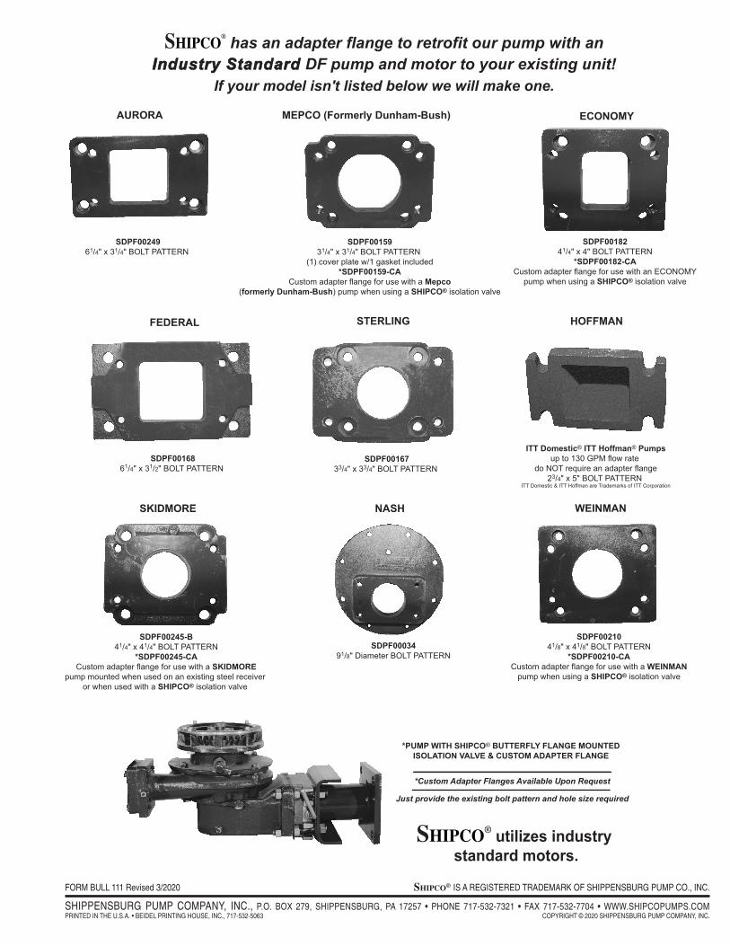
SHIPCO® has an adapter flange to retrofit our pump with an
IInndduussttrryy SSttaannddaarrdd DF pump and motor to your existing unit!If your model isn't listed below we will make one.
SHIPCO® utilizes industry standard motors.
SDPF0024961/4" x 31/4" BOLT PATTERN
AURORA
SDPF0015931/4" x 31/4" BOLT PATTERN
(1) cover plate w/1 gasket included*SDPF00159-CA
Custom adapter flange for use with a Mepco(formerly Dunham-Bush) pump when using a SHIPCO® isolation valve
MEPCO (Formerly Dunham-Bush)
SDPF0018241/4" x 4" BOLT PATTERN
*SDPF00182-CACustom adapter flange for use with an ECONOMY
pump when using a SHIPCO® isolation valve
ECONOMY
SDPF0016861/4" x 31/2" BOLT PATTERN
FEDERAL
*PUMP WITH SHIPCO® BUTTERFLY FLANGE MOUNTEDISOLATION VALVE & CUSTOM ADAPTER FLANGE
SDPF0003491/8" Diameter BOLT PATTERN
NASH
SDPF00245-B41/4" x 41/4" BOLT PATTERN
*SDPF00245-CACustom adapter flange for use with a SKIDMORE
pump mounted when used on an existing steel receiver or when used with a SHIPCO® isolation valve
SKIDMORE
*Custom Adapter Flanges Available Upon Request
Just provide the existing bolt pattern and hole size required
SDPF0021041/8" x 41/8" BOLT PATTERN
*SDPF00210-CACustom adapter flange for use with a WEINMAN
pump when using a SHIPCO® isolation valve
WEINMAN
SDPF0016733/4" x 33/4" BOLT PATTERN
STERLING
ITT Domestic® ITT Hoffman® Pumpsup to 130 GPM flow rate
do NOT require an adapter flange23/4" x 5" BOLT PATTERN
ITT Domestic & ITT Hoffman are Trademarks of ITT Corporation
HOFFMAN
FORM BULL 111 Revised 3/2020 Shipco® IS A REGISTERED TRADEMARK OF SHIPPENSBURG PUMP CO., INC.
SHIPPENSBURG PUMP COMPANY, INC., P.O. BOX 279, SHIPPENSBURG, PA 17257 • PHONE 717-532-7321 • FAX 717-532-7704 • WWW.SHIPCOPUMPS.COMPRINTED IN THE U.S.A. • BEIDEL PRINTING HOUSE, INC., 717-532-5063 COPYRIGHT © 2020 SHIPPENSBURG PUMP COMPANY, INC.


