
Shifting Lever RAPIDFIRE Plus 11-speed - Shimanosi.shimano.com/pdfs/dm/DM-SL0005-04-ENG.pdfMTB XTR...
20
(English) DM-SL0005-04 Dealer's Manual MTB XTR SL-M9000 DEORE XT SL-M8000 Shifting Lever RAPIDFIRE Plus 11-speed
Transcript of Shifting Lever RAPIDFIRE Plus 11-speed - Shimanosi.shimano.com/pdfs/dm/DM-SL0005-04-ENG.pdfMTB XTR...

(English) DM-SL0005-04
Dealer's Manual
MTB XTR
SL-M9000
DEORE XT SL-M8000
Shifting Lever
RAPIDFIRE Plus 11-speed

2
CONTENTS
IMPORTANT NOTICE ............................................................................................................................. 3
TO ENSURE SAFETY ............................................................................................................................. 4
LIST OF TOOLS TO BE USED ................................................................................................................. 7
INSTALLATION ...................................................................................................................................... 9
Installation to the handlebar (Normal specifications) ................................................................................ 9
Installation to the handlebar (I-spec II/I-spec B) .......................................................................................... 9 Compatibility of shifting lever and brake lever ........................................................................................................................ 9 I-spec II ......................................................................................................................................................................................... 9 I-spec B ...................................................................................................................................................................................... 11 Note: Number of front chainring positions and the lever position ....................................................................................... 12
MAINTENANCE ................................................................................................................................... 14
Replacing the inner cable .......................................................................................................................... 14
Replacement and re-arrangement of the indicator unit .......................................................................... 14 If there is no indicator unit ...................................................................................................................................................... 16 Re-arrangement to a configuration with no indicator unit (cover sold separately) ............................................................. 17
Replacement of the shifting lever unit ...................................................................................................... 18
IMPORTANT NOTICE
3
IMPORTANT NOTICE This dealer’s manual is intended primarily for use by professional bicycle mechanics.
Users who are not professionally trained for bicycle assembly should not attempt to install the components themselves using the dealer’s manuals. If any part of the information on the manual is unclear to you, do not proceed with the installation. Instead, contact your place of purchase or a local bicycle dealer for their assistance.
Make sure to read all instruction manuals included with the product.
Do not disassemble or modify the product other than as stated in the information contained in this dealer’s manual.
All dealer’s manuals and instruction manuals can be viewed on-line on our website (http://si.shimano.com).
Please observe the appropriate rules and regulations of the country, state or region in which you conduct your business as a dealer.
For safety, be sure to read this dealer’s manual thoroughly before use, and follow it for correct use.
The following instructions must be observed at all times in order to prevent personal injury and physical damage to equip-ment and surroundings. The instructions are classified according to the degree of danger or damage which may occur if the product is used incor-rectly.
DANGER
Failure to follow the instructions will result in death or serious injury.
WARNING
Failure to follow the instructions could result in death or serious injury.
CAUTION
Failure to follow the instructions could cause personal injury or physical damage to equipment and surroundings.
TO ENSURE SAFETY
4
TO ENSURE SAFETY
WARNING
Be sure to follow the instructions provided in the manuals when installing the product. It is recommended to use genuine Shimano parts only. If parts such as bolts and nuts become loose or damaged, the bicycle may suddenly fall over, which may cause serious injury. In addition, if adjustments are not carried out correctly, problems may occur, and the bicycle may suddenly fall over, which may cause serious injury.
Be sure to wear safety glasses or goggles to protect your eyes while performing maintenance tasks such as replacing
parts.
After reading the dealer's manual thoroughly, keep it in a safe place for later reference.
NOTE
Be sure to also inform users of the following:
Be sure to keep turning the crank during the shifting lever operation.
If gear shifting operations do not feel smooth, wash the derailleur and lubricate all moving parts.
Products are not guaranteed against natural wear and deterioration from normal use and aging.
For maximum performance we highly recommend Shimano lubricants and maintenance products.
For Installation to the Bicycle, and Maintenance:
Grease the inner cable and the inside of the outer casing before use to ensure that they slide properly.
Use an outer casing [OT-SP41] and a cable guide (SM-SP17/SP18) for smooth operation.
A special grease is used for the gear shifting cable. Do not use premium grease or other types of grease, otherwise they may cause deterioration in gear shifting performance.
Use an outer casing which still has some length to spare even when the handlebars are turned all the way to both sides. Furthermore, check that the shifting lever does not touch the bicycle frame when the handlebars are turned all the way.
If gear shifting adjustments cannot be carried out, check the alignment of the fork end and check if the cable is lubricated or if the outer casing is too long or too short.
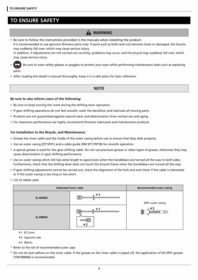
List of cables used
Dedicated inner cable Recommended outer casing
SL-M9000
SP41 outer casing
SL-M8000
1 Ø1.2mm
2 Opposite side
3 Ø4mm
* Refer to the list of recommended outer caps.
* Do not let dust adhere on the inner cable. If the grease on the inner cable is wiped off, the application of SIS SP41 grease (Y04180000) is recommended.
TO ENSURE SAFETY
5
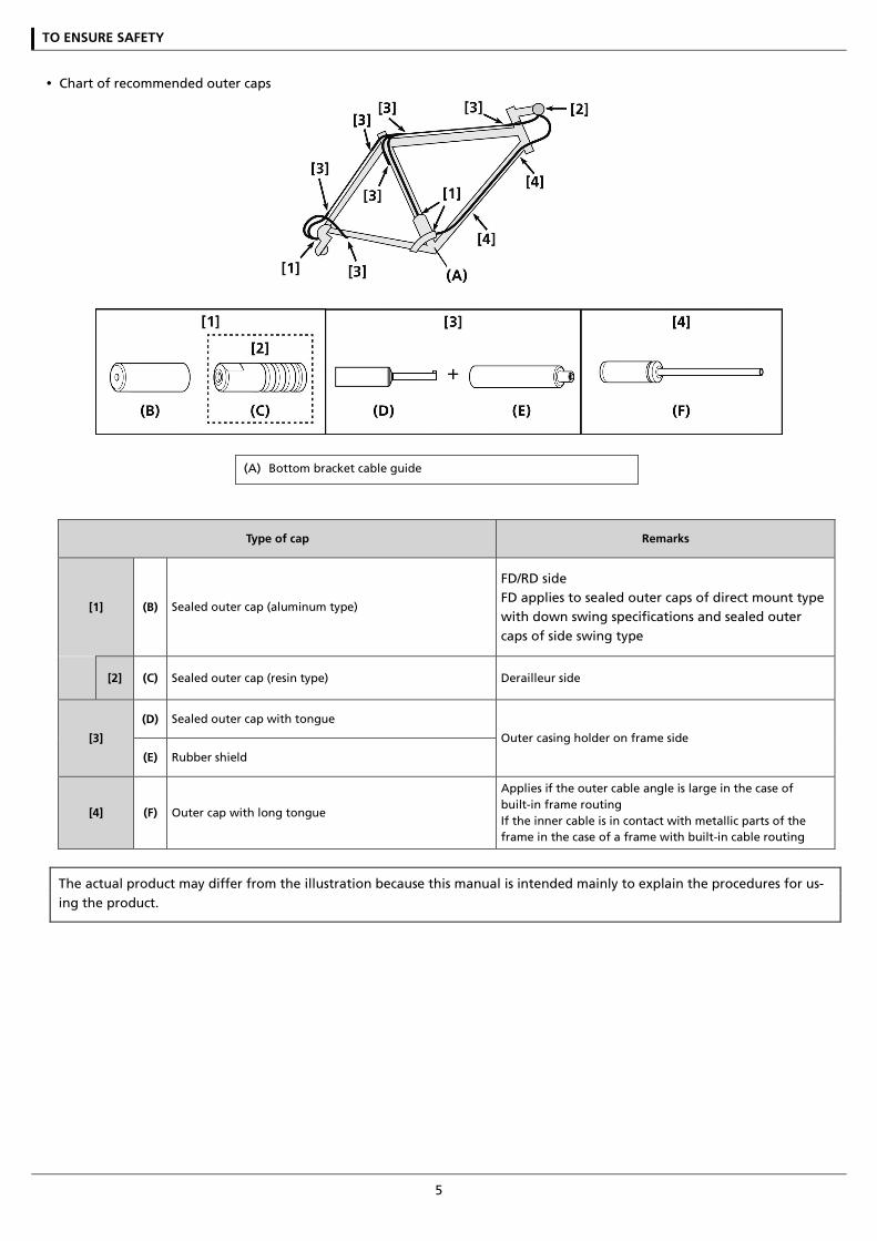
Chart of recommended outer caps
(A) Bottom bracket cable guide
Type of cap Remarks
[1] (B) Sealed outer cap (aluminum type)
FD/RD side FD applies to sealed outer caps of direct mount type with down swing specifications and sealed outer caps of side swing type
[2] (C) Sealed outer cap (resin type) Derailleur side
[3]
(D) Sealed outer cap with tongue
Outer casing holder on frame side
(E) Rubber shield
[4] (F) Outer cap with long tongue
Applies if the outer cable angle is large in the case of built-in frame routing If the inner cable is in contact with metallic parts of the frame in the case of a frame with built-in cable routing
The actual product may differ from the illustration because this manual is intended mainly to explain the procedures for us-ing the product.
LIST OF TOOLS TO BE USED

LIST OF TOOLS TO BE USED
7
LIST OF TOOLS TO BE USED The following tools are needed for installation, adjustment, and maintenance purposes.
Tool Tool Tool
2mm Allen key 4mm Allen key Screwdriver[#1]
3mm Allen key 7mm spanner Screwdriver[#2]

INSTALLATION
INSTALLATION
9
INSTALLATION
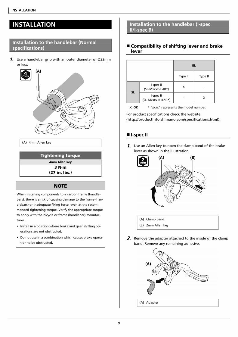
Installation to the handlebar (Normal specifications)
1. Use a handlebar grip with an outer diameter of Ø32mm or less.
(A) 4mm Allen key
Tightening torque 4mm Allen key
3 N·m {27 in. lbs.}
NOTE
When installing components to a carbon frame (handle-
bars), there is a risk of causing damage to the frame (han-
dlebars) or inadequate fixing force, even at the recom-
mended tightening torque. Verify the appropriate torque
to apply with the bicycle or frame (handlebar) manufac-
turer.
Install in a position where brake and gear shifting op-
erations are not obstructed.
Do not use in a combination which causes brake opera-
tion to be obstructed.
Installation to the handlebar (I-spec II/I-spec B)
Compatibility of shifting lever and brake lever
BL
Type II Type B
SL
I-spec II (SL-Mxxxx-IL/IR*)
X -
I-spec B (SL-Mxxxx-B-IL/IR*)
- X
X: OK * “xxxx” represents the model number.
For product specifications check the website (http://productinfo.shimano.com/specifications.html).
I-spec II
1. Use an Allen key to open the clamp band of the brake lever as shown in the illustration.
(A) Clamp band
(B) 2mm Allen key
2. Remove the adapter attached to the inside of the clamp band. Remove any remaining adhesive.
(A) Adapter
INSTALLATION
10
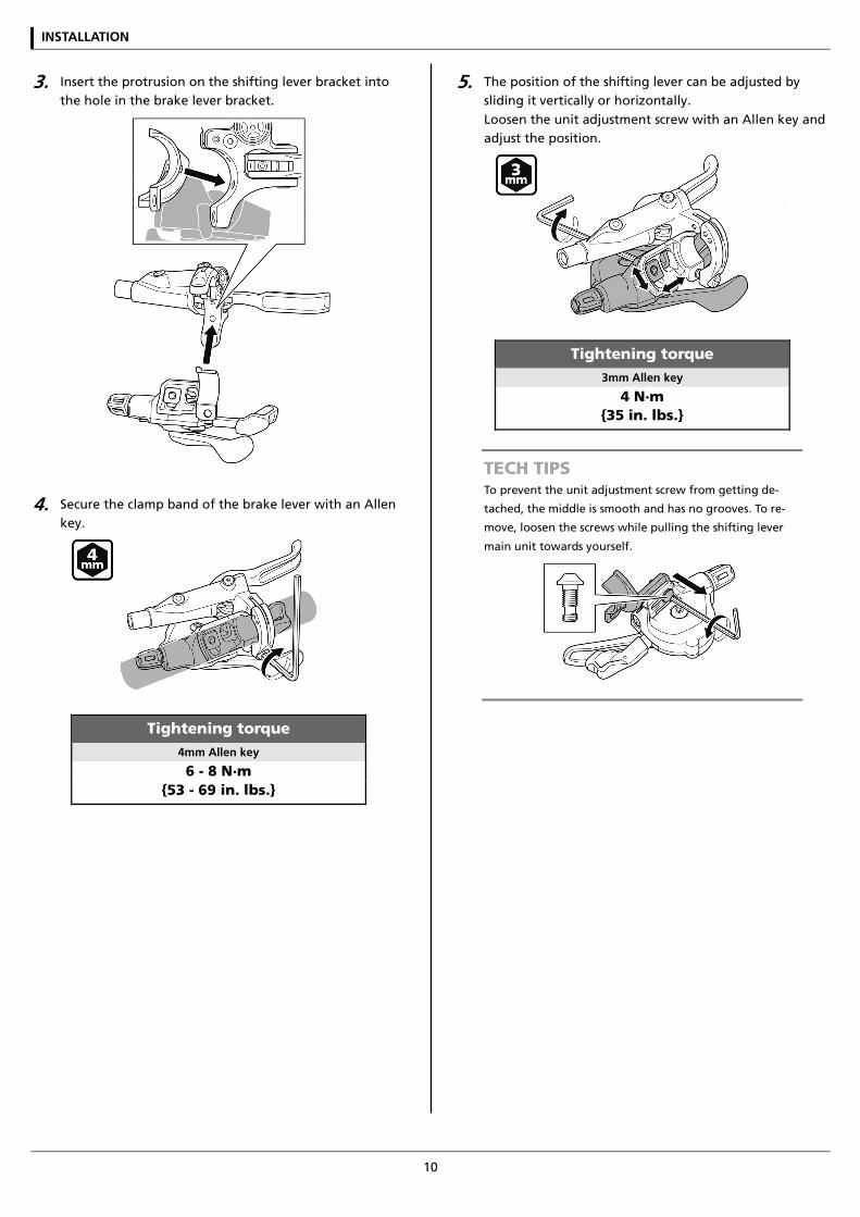
3. Insert the protrusion on the shifting lever bracket into the hole in the brake lever bracket.
4. Secure the clamp band of the brake lever with an Allen key.
Tightening torque 4mm Allen key
6 - 8 N·m {53 - 69 in. lbs.}
5. The position of the shifting lever can be adjusted by sliding it vertically or horizontally. Loosen the unit adjustment screw with an Allen key and adjust the position.
Tightening torque 3mm Allen key
4 N·m {35 in. lbs.}
TECH TIPS To prevent the unit adjustment screw from getting de-
tached, the middle is smooth and has no grooves. To re-
move, loosen the screws while pulling the shifting lever
main unit towards yourself.
INSTALLATION
11
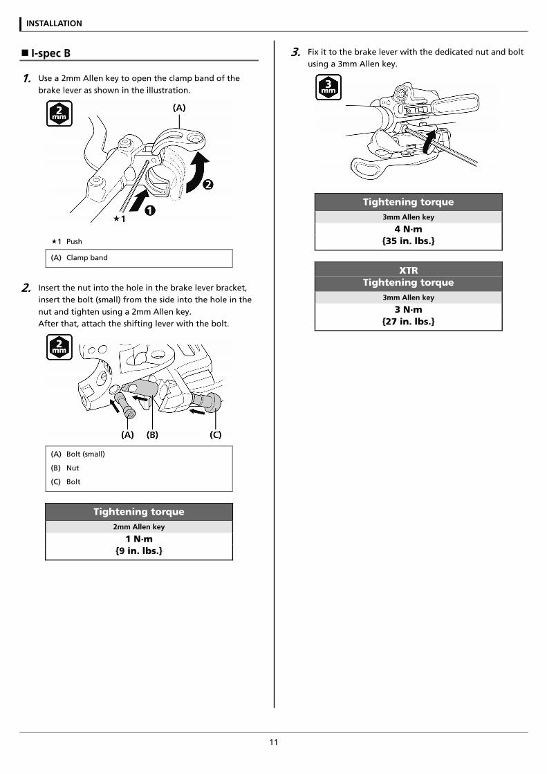
I-spec B
1. Use a 2mm Allen key to open the clamp band of the brake lever as shown in the illustration.
1 Push
(A) Clamp band
2. Insert the nut into the hole in the brake lever bracket, insert the bolt (small) from the side into the hole in the nut and tighten using a 2mm Allen key. After that, attach the shifting lever with the bolt.
(A) Bolt (small)
(B) Nut
(C) Bolt
Tightening torque 2mm Allen key
1 N·m {9 in. lbs.}
3. Fix it to the brake lever with the dedicated nut and bolt using a 3mm Allen key.
Tightening torque 3mm Allen key
4 N·m {35 in. lbs.}
XTR Tightening torque
3mm Allen key
3 N·m {27 in. lbs.}
INSTALLATION
12
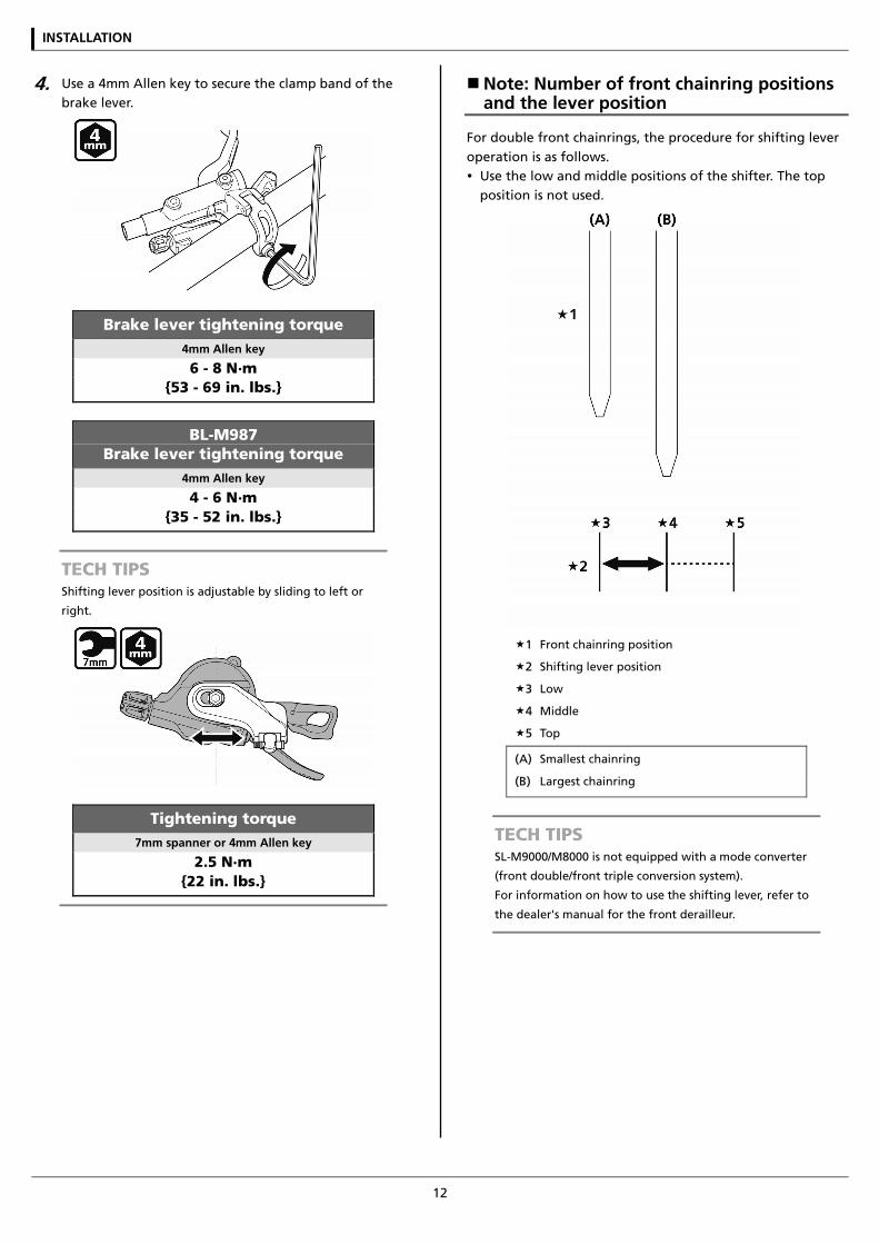
4. Use a 4mm Allen key to secure the clamp band of the brake lever.
Brake lever tightening torque 4mm Allen key
6 - 8 N·m {53 - 69 in. lbs.}
BL-M987 Brake lever tightening torque
4mm Allen key
4 - 6 N·m {35 - 52 in. lbs.}
TECH TIPS Shifting lever position is adjustable by sliding to left or
right.
Tightening torque 7mm spanner or 4mm Allen key
2.5 N·m {22 in. lbs.}
Note: Number of front chainring positions and the lever position
For double front chainrings, the procedure for shifting lever operation is as follows. Use the low and middle positions of the shifter. The top
position is not used.
1 Front chainring position
2 Shifting lever position
3 Low
4 Middle
5 Top
(A) Smallest chainring
(B) Largest chainring
TECH TIPS SL-M9000/M8000 is not equipped with a mode converter
(front double/front triple conversion system).
For information on how to use the shifting lever, refer to
the dealer's manual for the front derailleur.
MAINTENANCE
MAINTENANCE
14
MAINTENANCE
Replacing the inner cable
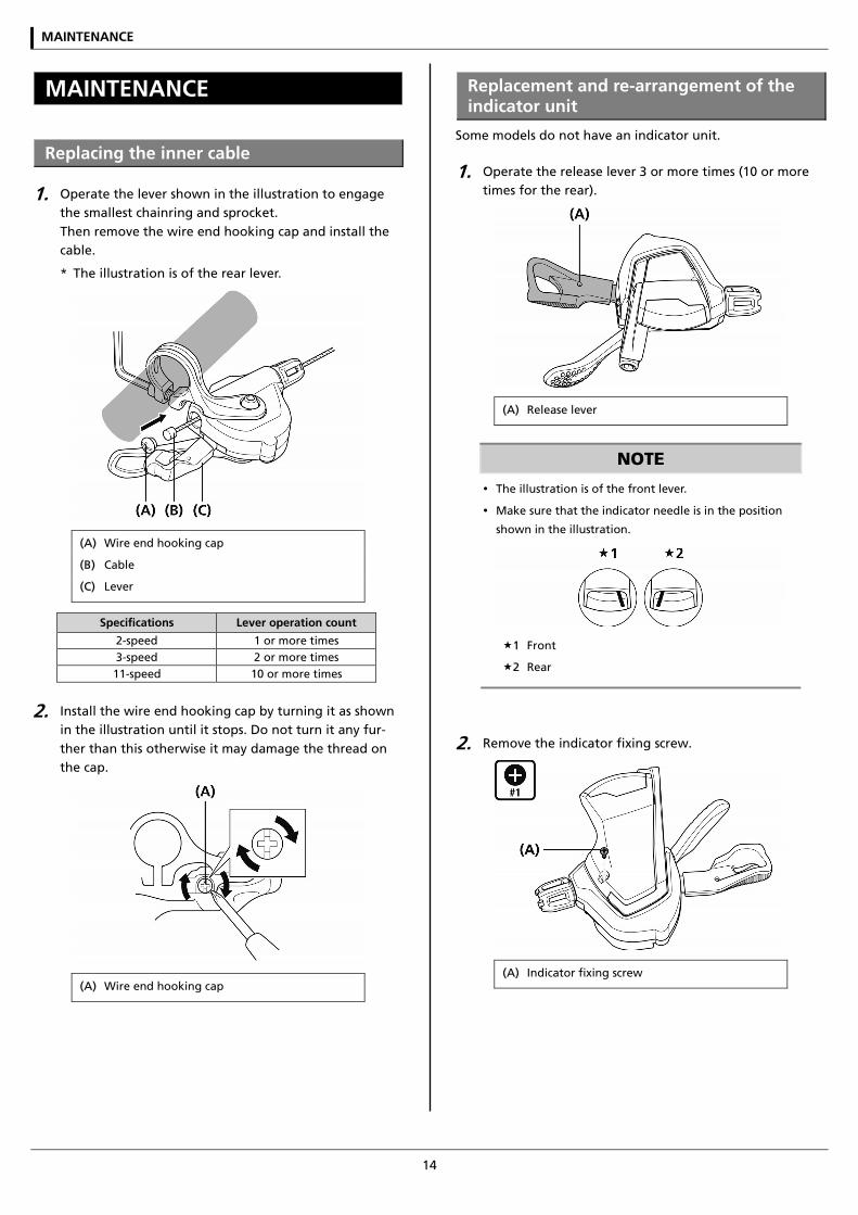
1. Operate the lever shown in the illustration to engage the smallest chainring and sprocket. Then remove the wire end hooking cap and install the cable.
* The illustration is of the rear lever.
(A) Wire end hooking cap
(B) Cable
(C) Lever
Specifications Lever operation count
2-speed 1 or more times 3-speed 2 or more times 11-speed 10 or more times
2. Install the wire end hooking cap by turning it as shown in the illustration until it stops. Do not turn it any fur-ther than this otherwise it may damage the thread on the cap.
(A) Wire end hooking cap
Replacement and re-arrangement of the indicator unit
Some models do not have an indicator unit.
1. Operate the release lever 3 or more times (10 or more times for the rear).
(A) Release lever
NOTE
The illustration is of the front lever.
Make sure that the indicator needle is in the position
shown in the illustration.
1 Front
2 Rear
2. Remove the indicator fixing screw.
(A) Indicator fixing screw
MAINTENANCE
15
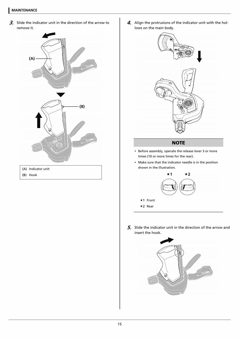
3. Slide the indicator unit in the direction of the arrow to remove it.
(A) Indicator unit
(B) Hook
4. Align the protrusions of the indicator unit with the hol-lows on the main body.
NOTE
Before assembly, operate the release lever 3 or more
times (10 or more times for the rear).
Make sure that the indicator needle is in the position
shown in the illustration.
1 Front
2 Rear
5. Slide the indicator unit in the direction of the arrow and insert the hook.
MAINTENANCE
16
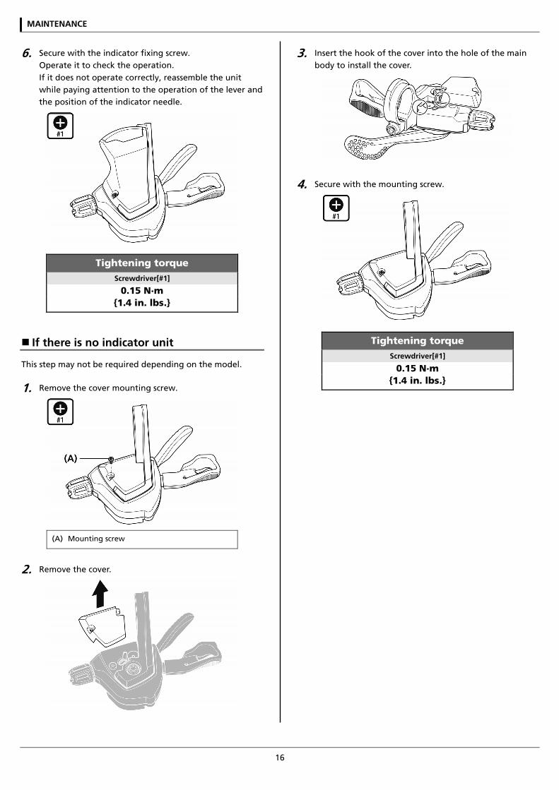
6. Secure with the indicator fixing screw. Operate it to check the operation. If it does not operate correctly, reassemble the unit while paying attention to the operation of the lever and the position of the indicator needle.
Tightening torque Screwdriver[#1]
0.15 N·m {1.4 in. lbs.}
If there is no indicator unit
This step may not be required depending on the model.
1. Remove the cover mounting screw.
(A) Mounting screw
2. Remove the cover.
3. Insert the hook of the cover into the hole of the main body to install the cover.
4. Secure with the mounting screw.
Tightening torque Screwdriver[#1]
0.15 N·m {1.4 in. lbs.}
MAINTENANCE
17
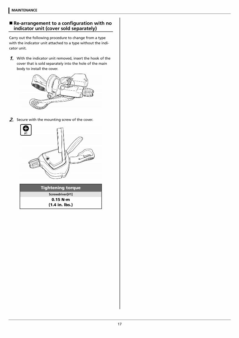
Re-arrangement to a configuration with no indicator unit (cover sold separately)
Carry out the following procedure to change from a type with the indicator unit attached to a type without the indi-cator unit.
1. With the indicator unit removed, insert the hook of the cover that is sold separately into the hole of the main body to install the cover.
2. Secure with the mounting screw of the cover.
Tightening torque Screwdriver[#1]
0.15 N·m {1.4 in. lbs.}

MAINTENANCE
18
Replacement of the shifting lever unit
Disassembly and assembly should only be carried out when replacing the shifting lever unit.
1. Loosen the cable fixing bolt (nut) of the front derailleur or rear derailleur, and then pull the inner cable out of the shifting lever unit in the same way as when in-stalling the inner cable.
2. Remove the adjustment bolt.
3. Remove the unit fixing bolt.
NOTE
Remove the indicator unit first for models which have an
indicator unit.
For normal type
(A) Unit fixing bolt (normal type)
Tightening torque 4mm Allen key
2.5 N·m {22 in. lbs.}
For I-spec II
(A) Unit fixing bolt (I-spec II)
Tightening torque 3mm Allen key
2.5 N·m {22 in. lbs.}
For I-spec B
(A) Unit fixing bolt (I-spec B)
Tightening torque 4mm Allen key or 7mm spanner
2.5 N·m {22 in. lbs.}
MAINTENANCE
19
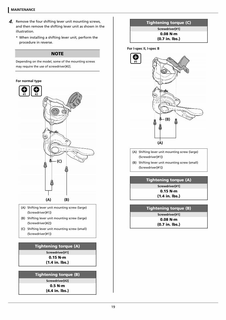
4. Remove the four shifting lever unit mounting screws, and then remove the shifting lever unit as shown in the illustration.
* When installing a shifting lever unit, perform the procedure in reverse.
NOTE
Depending on the model, some of the mounting screws
may require the use of screwdriver[#2].
For normal type
(A) Shifting lever unit mounting screw (large)
(Screwdriver[#1])
(B) Shifting lever unit mounting screw (large)
(Screwdriver[#2])
(C) Shifting lever unit mounting screw (small)
(Screwdriver[#1])
Tightening torque (A) Screwdriver[#1]
0.15 N·m {1.4 in. lbs.}
Tightening torque (B) Screwdriver[#2]
0.5 N·m {4.4 in. lbs.}
Tightening torque (C) Screwdriver[#1]
0.08 N·m {0.7 in. lbs.}
For I-spec II, I-spec B
(A) Shifting lever unit mounting screw (large)
(Screwdriver[#1])
(B) Shifting lever unit mounting screw (small)
(Screwdriver[#1])
Tightening torque (A) Screwdriver[#1]
0.15 N·m {1.4 in. lbs.}
Tightening torque (B) Screwdriver[#1]
0.08 N·m {0.7 in. lbs.}

Please note: specifications are subject to change for improvement without notice. (English) © March 2016 by Shimano Inc. HTR