
Shenandoah County, Virginia Request for Proposals for ... · Shenandoah County, Virginia . Request...
160
Shenandoah County, Virginia Request for Proposals for Project 25 Public Safety Radio Network Issued: October 12, 2017
Transcript of Shenandoah County, Virginia Request for Proposals for ... · Shenandoah County, Virginia . Request...

Shenandoah County, Virginia
Request for Proposals for
Project 25 Public Safety Radio Network
Issued: October 12, 2017

Request for Proposals Project 25 Public Safety Radio Network Shenandoah County, Virginia
i
TABLE OF CONTENTS
1. Project Overview ............................................................................................................ 1
Introduction ........................................................................................................................1
Background .........................................................................................................................1 1.2.1. Shenandoah County Overview ............................................................................................................ 1
Request for Proposal Overview ............................................................................................2
Project Summary .................................................................................................................4
Proposals Desired ................................................................................................................5 1.5.1. Systems ................................................................................................................................................ 5 1.5.2. Services ................................................................................................................................................ 6
Quality Assurance and Coordination ....................................................................................7 1.6.1. Standards and Guidelines .................................................................................................................... 7 1.6.2. P25 Standard Compliance ................................................................................................................... 8 1.6.3. Frequency Coordination and Licensing ............................................................................................... 8 1.6.4. Federal Aviation Administration (if applicable) ................................................................................... 9 1.6.5. Project Management ........................................................................................................................... 9 1.6.6. Project Meetings ............................................................................................................................... 11 1.6.7. Project Staffing .................................................................................................................................. 11 1.6.8. Quality Assurance/Quality Control Program ..................................................................................... 12
Delivery, Storage and Handling .......................................................................................... 13
Project Submittals ............................................................................................................. 13 1.8.1. Proposal ............................................................................................................................................. 14 1.8.2. Preliminary Design (45 days after notice to proceed) ....................................................................... 14 1.8.3. Final Design (90 days after notice to proceed) .................................................................................. 14 1.8.4. System Staging, Delivery and Installation ......................................................................................... 15 1.8.5. Final System Acceptance ................................................................................................................... 16
Overview .......................................................................................................................... 17
Mandatory Pre-Proposal Conference ................................................................................. 17
Schedule of Events ............................................................................................................ 18
Proposal Format ................................................................................................................ 18
Evaluation ......................................................................................................................... 21
Addenda to the Contract ................................................................................................... 21
Award of Contract ............................................................................................................. 21
2. Radio Communications System Requirements ............................................................... 23
Overview .......................................................................................................................... 23
Interoperability/P25 Statement of Requirements ............................................................... 23
System Configuration ........................................................................................................ 24 2.3.1. Redundancy and Survivability ........................................................................................................... 24

Request for Proposals 700 MHz, Project 25 Public Safety Radio Network Shenandoah County, Virginia
ii
2.3.2. Expansion .......................................................................................................................................... 25 2.3.3. Grade of Service ................................................................................................................................ 25
Site Selection .................................................................................................................... 26
Coverage ........................................................................................................................... 26 2.5.1. Coverage Maps .................................................................................................................................. 27 2.5.2. Map Criteria ....................................................................................................................................... 29 2.5.3. Coverage Model ................................................................................................................................ 29 2.5.4. TIA TSB-88 – User Choices ................................................................................................................. 30
Site Equipment .................................................................................................................. 31 2.6.1. Overview ........................................................................................................................................... 31 2.6.2. System and Site Control Equipment .................................................................................................. 31 2.6.3. Simulcast Equipment ......................................................................................................................... 32 2.6.4. Receiver Voting ................................................................................................................................. 32 2.6.5. Base Station Equipment .................................................................................................................... 32 2.6.6. Antenna Systems ............................................................................................................................... 33 2.6.7. Antenna Installation .......................................................................................................................... 33 2.6.8. Removal of Existing Infrastructure and Equipment ........................................................................... 35
Network Management System .......................................................................................... 35 2.7.1. Network Management Terminal ....................................................................................................... 37 2.7.2. Remote Terminal Units ...................................................................................................................... 39
Shared Switch – Option ..................................................................................................... 40
Mobile Data – Option ........................................................................................................ 40
Backup Consolettes – Option ............................................................................................. 41
3. Backhaul Network ........................................................................................................ 42
Overview .......................................................................................................................... 42
Digital Microwave Network ............................................................................................... 42 3.2.1. Requirements .................................................................................................................................... 42 3.2.2. Microwave Engineering ..................................................................................................................... 45
4. Site Development ......................................................................................................... 46
General ............................................................................................................................. 46
Towers .............................................................................................................................. 48
Shelters............................................................................................................................. 50
Generator and Automatic Transfer Switch ......................................................................... 55 4.4.1. Diesel Generator ............................................................................................................................... 57 4.4.2. Automatic Transfer Switch ................................................................................................................ 60 4.4.3. Diesel Fuel System ............................................................................................................................. 63
DC Power .......................................................................................................................... 63
Site Preparation ................................................................................................................ 65
Fencing ............................................................................................................................. 68

Request for Proposals 700 MHz, Project 25 Public Safety Radio Network Shenandoah County, Virginia
iii
5. Dispatch Consoles ......................................................................................................... 71
General Requirements and Features .................................................................................. 71
Trunked Requirements ...................................................................................................... 72
Conventional Requirements .............................................................................................. 74
Paging Requirements ........................................................................................................ 74
Systems Integration .......................................................................................................... 75
Logging Recorder ............................................................................................................... 75
Operator Position Equipment ............................................................................................ 76
Common Electronics Equipment ........................................................................................ 76
6. Warranty, Maintenance, and Support ........................................................................... 78
Warranty .......................................................................................................................... 78
Maintenance ..................................................................................................................... 78 6.2.1. General Requirements ...................................................................................................................... 78 6.2.2. Maintenance Standards .................................................................................................................... 79
Parts Availability ............................................................................................................... 80
Spare Equipment ............................................................................................................... 80
Lifecycle Cost – Option ...................................................................................................... 81
7. System Implementation, Test and Acceptance ............................................................... 82
General ............................................................................................................................. 82
Cutover Plan ..................................................................................................................... 82
Staging .............................................................................................................................. 82
System Installation ............................................................................................................ 83
Coverage Testing ............................................................................................................... 84
30-day Operational Test .................................................................................................... 86
Training ............................................................................................................................ 86
Final Acceptance Testing ................................................................................................... 88
As-Built Documentation .................................................................................................... 89
System Acceptance ........................................................................................................... 89
8. Subscriber Equipment ................................................................................................... 90
Overview .......................................................................................................................... 90
General Requirements ....................................................................................................... 90 8.2.1. Portable Radios ................................................................................................................................. 91 8.2.2. Mobile Radios/Control Stations ........................................................................................................ 94 8.2.3. Fleet Mapping.................................................................................................................................... 96
Subscriber Warranty and Maintenance .............................................................................. 96

Request for Proposals 700 MHz, Project 25 Public Safety Radio Network Shenandoah County, Virginia
iv
8.3.1. Subscriber Warranty .......................................................................................................................... 96 8.3.2. Subscriber Maintenance .................................................................................................................... 97
9. County Terms and Conditions ........................................................................................ 98
Glossary of Terms and Acronyms ....................................................................................... 107
Appendix A: Proposal Form ................................................................................................ 114
Appendix B: Proposal Pricing Forms ................................................................................... 117
Appendix C: Potential Candidate Tower Sites ..................................................................... 147
Appendix D: Compliance Matrix ......................................................................................... 148
Appendix E: Coverage Requirements Map .......................................................................... 154
Appendix F: Local Telecommunications Provider Fiber-Optic Network ................................ 155

Request for Proposals Project 25 Public Safety Radio Network Shenandoah County, Virginia
1
1. PROJECT OVERVIEW
INTRODUCTION
Shenandoah County, Virginia, (County) invites proposals from qualified vendors for the provision of an Association of Public-Safety Communications Officials, International (APCO) Project 25 (P25) radio communications system to support mission-critical public safety communications within the county. The proposed communications system shall provide enhanced, two-way wireless communications capabilities to all public safety users. Proposals are requested for the following:
1. A new P25 system (trunked Phase II or conventional) to replace the County’s existing
ultra-high frequency (UHF) conventional analog system
2. A new Internet Protocol (IP)-based microwave or terrestrial fiber backhaul system
3. New radio dispatch consoles for six positions at the County’s Enhanced 911 (E911) Center
4. Mobile and portable subscriber radios for the County’s first responders
5. Simulcast tone-and-voice paging
6. Civil work to support upgrades to new and existing radio sites, and tower upgrades to
support the aforementioned communications subsystems
In addition to the above, Respondents should address in their proposals system installation and commissioning, and ongoing maintenance support, to ensure a state-of-the-art system.
The proposed system will be owned by Shenandoah County. The system procurement
process is being administered by Shenandoah County. For brevity, the generic term “County” used throughout this Request for Proposal (RFP) refers to Shenandoah County, unless otherwise specified.
BACKGROUND
1.2.1. Shenandoah County Overview
A. The County’s Department of Emergency Communications (DEC) provides E911 services for all communities in the county, and dispatching services for five law enforcement agencies and 12 fire/rescue departments. The DEC also handles requests for other local government entities and is in regular communication with the Virginia State Police and adjoining public safety agencies.
B. The public-safety first responders—law enforcement, fire/rescue, and emergency
medical services (EMS)—within Shenandoah County long have been aware of radio
Request for Proposals Project 25 Public Safety Radio Network Shenandoah County, Virginia
2
system deficiencies that can and have negatively impacted the ability of first responders to communicate during both routine and critical incidents.
C. The current public safety radio system uses three sites and operates on UHF
frequencies in conventional analog mode. Various elements of the system have been installed over the last 20 years.
D. Numerous critical issues are affecting the current system. These issues include:
1. A lack of coverage and unreliable performance exist in many areas within the
county. The system design is insufficient to provide reliable public safety-grade radio system performance.
2. Interoperability is limited both within the county and with external agencies. This makes agency-to-agency communication cumbersome and less than reliable.
3. The current system design includes single points of failure that can leave first responders with no reliable way to be dispatched, or to communicate, for an extended period if a failure does occur. Combined with the reduced reliability of aging components, the overall system is susceptible to failures.
4. Channel capacity is very limited due to the conventional design, with channels being transmitted from only one site and a limited number of available frequencies.
5. Modern radio safety features, such as an emergency button and encryption for specialty units, are unavailable today.
E. The existing communications system cannot be upgraded to meet these
requirements in its present configuration.
F. It is anticipated that some of the County’s existing tower sites will be utilized for the new systems, and that additional tower sites will be added to improve coverage, including replacing towers at the DEC and building a new tower in Fort Valley. Civil work is required to upgrade existing towers and support facilities, as well as to develop new radio sites for the expanded network. It is anticipated that the work may include development of both raw-land sites, existing leased tower sites and new site locations that are existing but not currently part of the County systems.
REQUEST FOR PROPOSAL OVERVIEW
This section provides a high-level overview of this RFP.
1. Section 1, Project Overview – This section provides background information and a
general overview of the requirements contained in this RFP.
2. Section 2, Instructions to Respondents – This section provides instructions to Respondents, including, but not limited to: proposal due date, pre-proposal conference information, and evaluation criteria.

Request for Proposals Project 25 Public Safety Radio Network Shenandoah County, Virginia
3
3. Section 3, Radio Communications System Requirements – This section provides requirements for the desired communications systems. The County requires procurement of a UHF, P25 radio system. This section includes requirements for system configuration, site selection, radio frequency (RF) coverage, and site equipment. Subsections address the need for new radio dispatch consoles, network management system, and UHF tone-and-voice paging.
4. Section 4, Backhaul Network – This section provides requirements for digital microwave
backhaul equipment, consideration of fiber-optic network connectivity as an option, network management, and engineering.
5. Section 5, Site Development – If new or additional sites are necessary, this section
provides requirements for site development work, including site compound preparation, site grounding, tower deployment, shelter deployment, and electrical and generator systems.
6. Section 6, Dispatch Consoles – This section provides requirements for the new dispatch
console system and related equipment.
7. Section 7, Warranty, Maintenance, and Support – This section provides details for the existing towers to be analyzed under, and remediated to, current tower standards.
8. Section 8, System Implementation, Test and Acceptance – This section provides
requirements for training programs to be developed by the selected Respondent.
9. Section 9, Training – This section provides requirements for the warranty, extended warranty, maintenance, and support of the proposed system and subsystems.
10. Section 10, Subscriber Equipment – This section provides requirements for system
cutover, staging, installation, fleet mapping, coverage testing, and final acceptance.
11. Section 11, County Terms and Conditions – This section provides requirements for County terms and conditions, as well as subscriber equipment, including mobiles, portables, and control stations.
12. Glossary – A glossary of key terms contained in this RFP also is provided.
A. Several appendices also included with this RFP:
1. Appendix A: Proposal Form
2. Appendix B: Proposal Pricing Forms
3. Appendix C: Potential Candidate Tower Sites
4. Appendix D: Compliance Matrix
5. Appendix E: Coverage Requirements Map
Request for Proposals Project 25 Public Safety Radio Network Shenandoah County, Virginia
4
6. Appendix F: Local Telecommunications Provider Fiber-Optic Network Map
PROJECT SUMMARY
The selected Respondent shall provide the following project components:
1. Furnish and install system equipment and ancillary facilities
2. Engineering, system design, and Federal Communications Commission (FCC) licensing
preparation
3. Project management
4. Software installation and programming
5. Training
6. Acceptance testing, including coverage testing
7. Cutover plan and execution
8. Warranty and maintenance
The selected Respondent shall furnish the following complete, highly redundant, and/or fully functional systems and equipment.
1. P25 land mobile radio (LMR) communications system, including the guarantee of system
coverage and reliability
2. Point-to-point digital microwave backhaul network for primary connectivity, with consideration given to using fiber-optic network connectivity as an option. See Appendix F for a map of the local fiber-optic network and Appendix C for a candidate site list with fiber connectivity
3. Infrastructure facilities (e.g., towers, shelters, fencing)
4. Network management system (NMS)
5. Subscriber mobile and portable radio equipment
All equipment shall be provided in new condition and be covered by a full factory and/or
manufacturer’s warranty of not less than one year starting at the time of system acceptance.
The County prefers that existing radio tower sites be utilized in the new system design, if possible. Respondents may utilize other towers, or propose greenfield construction of new towers, if doing so improves system coverage and helps realize the coverage goals. The cost

Request for Proposals Project 25 Public Safety Radio Network Shenandoah County, Virginia
5
effectiveness of new greenfield towers versus adding other existing towers to the network will be an evaluation factor.
Existing towers may require structural modifications to support the proposed new system and
transitional loading. Respondents should account for the time required to remediate these towers, including time required for engineering, design, procurement, and implementation of any required modifications.
In the event additional or alternate tower sites are proposed to meet a Respondent’s
coverage guarantee, the response must include letters of commitment from those site and tower owners indicating availability of tower space to accommodate the proposed facilities and antennas. Such letters also must indicate a commitment to enter into negotiations with the County for tower space or construction on greenfield sites.
Work shall be planned, coordinated, and conducted with minimal interruption of service to
existing critical systems.
Proposals shall completely describe the equipment and methods that will be used to implement the system. The intent of this document is to allow the Respondent to propose the best equipment, technology and methods available to provide state-of-the-art public safety communications systems of the highest quality and performance.
Proposals shall not be accepted that include systems or equipment within five years of the
end of their respective lifecycles at the time of system acceptance.
Proposals shall not be accepted that include systems or equipment that will no longer be supported for software, spare parts, and repair by the Respondent or manufacturer within 15 years of system acceptance. Product roadmaps must be provided.
In the event that requirements are stated in more than one section and appear to conflict, the
more stringent requirement shall apply.
PROPOSALS DESIRED
The County desires a complete turnkey solution addressing all project systems, subsystems and components.
1.5.1. Systems
A. This RFP seeks proposals for the construction of a countywide radio system that will
include:
1. UHF, P25 system that will support first responders within Shenandoah County
2. Trunked or conventional system to meet the capacity requirements of the County
3. Tone-and-voice paging system with a standalone simulcast channel

Request for Proposals Project 25 Public Safety Radio Network Shenandoah County, Virginia
6
4. P25 dispatch consoles
5. Construction of a microwave network that will provide radio system backhaul for P25 traffic at each site, with consideration of a fiber-optic network for connectivity as an option
6. Purchase of P25 subscriber units (mobiles, portables and control stations) and
any necessary pagers
7. Site construction/improvements
1.5.2. Services
A. Design and engineer the P25 radio system to provide 95 percent mobile coverage countywide and 95 percent portable radio coverage in a 6-decibels (dB) building within the defined portable coverage area, with the portable carried on the user’s belt with a radio-mounted antenna and a wired speaker/microphone.
B. Design and engineer a microwave system to interconnect the LMR sites and E9-1-1
Center, with consideration of a fiber-optic network for connectivity as an option.
C. Conduct a structural analysis of all towers proposed for use in the system and mitigate any structural shortfalls to meet the current Telecommunications Industry Association (TIA) 222-G, Structural Standard for Antenna Supporting Structures and Antennas, Class III standard.
D. Proposal Options: Requirements described as an “OPTION” or “OPTIONAL” refer to
features or equipment that may or may not be purchased by the County, or items whose quantities are not determined yet. It is not the Respondent’s option to respond to these requirements; therefore, the Respondent is required to respond to all OPTIONAL requirements to the greatest extent possible.
E. Alternate Proposals:
1. In the event that the Respondent has a technological solution that does not meet
the exact requirements in this specifications document, the Respondent may offer more than one proposal, as long as each proposal fully addresses the intent of the requirements set forth in this document.
2. Alternate proposals shall be submitted separately under a different cover from
the base proposal and clearly marked “ALTERNATE PROPOSAL.”
3. The Respondent shall comply with the same submittal instructions in Section 2.4, Proposal Format, below.

Request for Proposals Project 25 Public Safety Radio Network Shenandoah County, Virginia
7
QUALITY ASSURANCE AND COORDINATION
1.6.1. Standards and Guidelines
A. The Respondent shall comply with the following standards, rules, regulations and
industry guidelines:
1. American National Standards Institute (ANSI)
2. National Electrical Manufacturers Association (NEMA)
3. Electronics Industry Association (EIA)
4. Telecommunications Industry Association (TIA)
5. Telecommunications Distribution Methods Manual (TDMM)
6. National Electrical Code (NEC)
7. Institute of Electrical and Electronics Engineers (IEEE)
8. Federal Communications Commission (FCC)
9. Underwriters Laboratories, Inc. (UL)
10. American Society of Testing Materials (ASTM)
11. National Fire Protection Association (NFPA) 1221
12. Other contractor/industry standards
i. Respondents shall provide information to the County for review and approval prior to contract award.
B. The Respondent shall comply with industry best practices for system installation,
grounding, bonding and transient voltage surge suppression (TVSS), as outlined in the following standards:
1. Motorola R56®, Standards and Guidelines for Communication Sites (latest
revision)
2. Harris AE/LTZ 123 4618/1, Grounding Guidelines
3. Equivalent (Respondent must provide detail)

Request for Proposals Project 25 Public Safety Radio Network Shenandoah County, Virginia
8
C. Governing codes and conflicts: If the requirements of this specifications document conflict with those of the governing codes and regulations, then the more stringent of the two shall become applicable.
D. If the Respondent cannot meet any of the standards or guidelines listed above,
Respondent shall list in its proposal any and all deviations for approval by the County.
E. The Respondent shall identify and coordinate all necessary codes, permitting, etc.,
including building permits. The Respondent shall notify the County of any issues.
F. Respondent shall be responsible for performing a structural analysis for each tower where loading will be modified, and for advising the County where remediation will be required and the cost options for proposed modifications.
1.6.2. P25 Standard Compliance
A. The proposed trunked or conventional radio system shall comply with the latest
applicable P25 suite of standards adopted as TIA and/or ANSI documents at the time of proposal submission.
B. The system shall be delivered in accordance with the P25 Phase I and Phase II
standards outlined in this RFP. If these standards change or are updated for final release, the selected Respondent shall implement the final standards at no additional charge to the County.
C. The proposed system shall not include proprietary features that prohibit or impede
the use of P25-compliant subscriber equipment provided by any equipment vendor. Any proprietary features that would be available as an option should be clearly explained.
1.6.3. Frequency Coordination and Licensing
A. LMR Licenses: It is the County’s desire to operate exclusively in the UHF band.
The Respondent shall be responsible for the research and preparation of all license acquisitions to support the new system. Following approval of the preliminary design phase, the Respondent shall provide all modifications and applicable forms to the County for review and approval. The availability of adequate spectrum may be assumed by the Respondent. The County shall be responsible for coordination and licensing fees, if any, and signatures, as applicable.
B. Microwave Licenses: The Respondent shall be responsible for all microwave
frequency research, prior coordination and preparation of all associated FCC license applications and submittals on behalf of the County. The County shall be responsible for coordination and licensing fees, if any, and signatures, as applicable.

Request for Proposals Project 25 Public Safety Radio Network Shenandoah County, Virginia
9
1.6.4. Federal Aviation Administration (if applicable)
A. The Respondent shall complete Federal Aviation Administration (FAA) forms as necessary. Respondent also shall complete any associated FCC Antenna Structure Registration (ASR) submittals.
1.6.5. Project Management
A. The Respondent shall provide a project management plan (PMP) that provides
detail on the following: Project scope, deliverables, schedule, quality assurance/quality control (QA/QC) processes, and risk management.
B. The PMP shall describe how the Respondent intends to monitor and control the
installation and deployment of the proposed system and mitigate risks to ensure that the system meets the design specifications and is delivered on time.
C. Regularly scheduled status meetings shall be established between the County’s
project team and the successful Respondent. The Respondent shall provide a schedule for these meetings subject to the County’s approval.
Scheduling
A. The Respondent shall develop and maintain a project schedule including tasks,
milestones, start and end dates, task precursors and task owners.
B. The schedule shall represent tasks associated with completing work and shall be updated with actual dates as tasks are completed.
C. The updated schedule shall be provided as an agenda item for all
County/Respondent status meetings.
D. The schedule shall address the following at a minimum:
1. Site surveys
2. Detailed design review
3. Site preparation
4. Equipment manufacturing
5. Factory acceptance test
6. Equipment delivery
7. System installation
8. System configuration

Request for Proposals Project 25 Public Safety Radio Network Shenandoah County, Virginia
10
9. System optimization
10. Acceptance testing
11. Coverage testing
12. User training
13. Fleet map development
14. System cutover
15. System documentation development and delivery
16. System and equipment warranty
Project Punch List
A. The successful Respondent shall establish and maintain a punch list, as mutually
agreed to with the County, for site facilities, equipment and acceptance tests.
B. The punch list shall be maintained in real time and published weekly. The punch list shall include the following at a minimum:
1. Sequential punch-list item numbers
2. Date identified
3. Item description
4. The party responsible for resolution
5. Expected resolution date
6. Resolution date
7. Details about how each punch-list item was resolved and tested
8. Notes about the item
C. The Respondent shall be responsible for reviewing each punch-list item and
advising the County of any changes. The status of punch-list items shall be updated during each status meeting.

Request for Proposals Project 25 Public Safety Radio Network Shenandoah County, Virginia
11
1.6.6. Project Meetings
A. A project kickoff meeting shall be scheduled prior to the beginning of the project.
B. Regular project status meetings shall be scheduled following contract award and the initial kickoff meeting.
C. The successful Respondent shall be responsible for scheduling the meetings as
well as preparing meeting agendas and minutes. In addition to those identified in Section 1.6.5.1 above, meeting agenda items shall include, at a minimum, the following items:
1. Schedule review
2. Status of deliverables
3. Risk items
4. Changes
5. Action-item assignments
1.6.7. Project Staffing
A. Project staffing shall be managed by the successful Respondent based on
workload and the level of effort required throughout the implementation/installation process; however, the positions identified below shall be staffed throughout the duration of the project and shall not be changed without prior approval of the County.
B. Respondent’s Project Manager:
1. Respondent’s project manager shall be the primary point of contact between
the County and the Respondent.
2. Respondent’s project manager shall: bear full responsibility for supervising and coordinating the installation and deployment of the communications system; be responsible for development and acceptance of the PMP; manage the execution of the project against that plan; and oversee the day-to-day project activities, deliverables and milestones completion.
3. Respondent’s project manager shall be responsible for coordination of the
regular project status meetings.

Request for Proposals Project 25 Public Safety Radio Network Shenandoah County, Virginia
12
C. Respondent’s Project Engineer:
1. Respondent’s project engineer shall have the primary responsibility for managing the system design and ensuring that the system is installed in accordance with the approved system design.
2. Any deviation from the system design shall be subject to project change control
procedures and will not be undertaken until approved by the County.
3. Respondent’s project engineer shall ensure the development of block diagrams, system-level diagrams, and rack diagrams to assist the installation team in completing the system installation.
4. The project engineer also shall supervise the development and execution of
the acceptance test plan (ATP) and coverage acceptance test plan (CATP), and guide the County’s project team through the processes and procedures necessary to prove that the system performs as specified in the contract. No test plan will be executed until approved by the County.
1.6.8. Quality Assurance/Quality Control Program
A. The successful Respondent shall include a QA/QC plan. The QA/QC plan shall be
submitted for review during preliminary design as described in this section. The plan shall address all stages of the project, including at a minimum:
1. Procurement
2. System design
3. Installation
4. Implementation
5. Testing
6. Cutover
B. The QA/QC plan shall specifically describe the plans and procedures that ensure
the proposed system is designed in accordance with the standards and requirements described in this specifications document.
C. The QA/QC plan shall be included as part of the PMP developed by the project
manager.
D. The QA/QC plan shall be an integral part of the project and include County personnel as part of the review-and-approval process for all deliverables and submittals.

Request for Proposals Project 25 Public Safety Radio Network Shenandoah County, Virginia
13
E. The proposed QA/QC plan shall address the following project tasks at a minimum:
1. Design analysis and verification
2. RF coverage analysis and verification
3. Design changes and document control
4. Material shipping, receiving and storage
5. Site preparation (if required)
6. Field installation and inspection
7. Equipment inventory and tracking
8. System testing and validation
9. Software regression testing
10. Deficiency reporting and correction
11. Implementation and cutover
12. Training and certification
DELIVERY, STORAGE AND HANDLING
The selected Respondent shall be responsible for the storage of equipment following shipment from staging. All costs associated with the storage shall be the responsibility of the selected Respondent. The County shall not be liable for equipment or material stored onsite prior to installation.
PROJECT SUBMITTALS
Key project deliverables and submittals are outlined below and are described in further detail
throughout this specifications document.
All project submittals shall be subject to review and approval by the County and its engineer/consultant.
All submittals shall be provided in hard copy, properly bound, and in electronic format on a
USB flash drive. The quantity of hard copies required shall vary for each type of submittal and shall be determined by the County prior to submission.
All submittals shall include a cover letter or letter of transmittal, signed, dated and fully
describing the contents of the submittal.

Request for Proposals Project 25 Public Safety Radio Network Shenandoah County, Virginia
14
For the duration of the project Respondent shall provide a Web-based portal or File Transfer Protocol (FTP) site for sharing and exchanging project documents.
1.8.1. Proposal
A. Respondents shall submit their proposals in accordance with the date and time
specified in Section 2.1, Overview, below. Proposal format and submittal details are provided in Section 2.4, Proposal Format, below.
1.8.2. Preliminary Design (45 days after notice to proceed)
A. The successful Respondent shall submit the preliminary design package 45 days
after receiving the notice to proceed. The preliminary design package shall include the following:
1. QA/QC plan
2. Detailed project schedule
3. System-level block diagrams
4. Patching schedules and termination details for all cabling necessary for a
complete record of the installation
5. Radio and microwave channel plans
6. Microwave path engineering report(s)
7. Equipment room overview drawings
8. Equipment rack/cabinet elevation drawings
9. Tower profile drawings indicating antenna-mounting locations
10. Detailed lists of materials for each site
11. 30-day operational test plan
12. CATP
1.8.3. Final Design (90 days after notice to proceed)
A. The contract design review (CDR) shall occur no sooner than 90 days after the selected Respondent receives the notice to proceed unless the County agrees to an earlier date, or before the proposed sites acquisition can be validated and the County provides confirmation.

Request for Proposals Project 25 Public Safety Radio Network Shenandoah County, Virginia
15
B. The CDR shall be delayed until proposed sites in the Respondent’s design can be validated, acquired and finalized.
C. Selected Respondent shall submit the final design package no earlier than 90 days
after receiving notice to proceed, which shall include the following:
1. Any updates to previously submitted design information
2. Cutover plan
3. System operation and maintenance manuals for all equipment
4. Factory test data
5. Site installation drawings
6. Structural analyses and results
7. A detailed preliminary staging acceptance test plan (SATP) outlining a comprehensive series of tests that will demonstrate proof of performance and readiness for shipment
D. The final SATP shall be submitted no later than 15 business days before the
testing starts, and shall be approved no later than five business days before the testing starts
1.8.4. System Staging, Delivery and Installation
A. System staging shall not occur earlier than the final CDR approval or site validation
and acquisition.
B. System staging must be performed in the United States.
C. The Respondent shall submit a bill of materials/packing list with two copies for each shipment of equipment. The packing list shall include the following information at a minimum for each component included in the packaging:
1. Manufacturer
2. Model
3. Serial number
4. Unique identification of the package containing the item
D. All items shipped by Respondent or its suppliers will include the above information
in a barcode format.

Request for Proposals Project 25 Public Safety Radio Network Shenandoah County, Virginia
16
1.8.5. Final System Acceptance
A. Respondent shall submit a detailed final acceptance test plan (FATP) that outlines a comprehensive series of tests that will demonstrate proof of performance and readiness for final acceptance by the County/Owner.
B. The final FATP shall be submitted no later than 15 business days before the testing
starts, and shall be approved by the County before it is considered finalized. A preliminary FATP will be submitted with the Respondent’s proposal.
C. The Respondent shall submit three final and complete sets of as-built
documentation, including the following:
1. Documentation index
2. Field test reports, with dates and actual readings
3. Coverage test reports
4. Warranty documentation
5. Detailed list of materials for each site
6. A copy of all red-line documents for each site prior to issuance of the as-built documentation
7. As-built system-level block diagrams
8. As-built site drawings, including all cabling and terminations
9. Site layout drawings, as appropriate
10. Tower drawings showing any new installations

Request for Proposals Project 25 Public Safety Radio Network Shenandoah County, Virginia
17
Instructions to Respondents
OVERVIEW
Proposals must be received by 3:00 p.m. Eastern Time (ET) on December 8, 2017.
Respondents shall submit a bound original and nine bound copies of the proposal to the County. Each package also shall include a copy of the proposal in electronic format on USB flash drive. The front of the package shall be marked “Proposal for County of Shenandoah Radio Communications System.” Proposals shall be addressed to:
SHENANDOAH COUNTY P25 RADIO SYSTEM PROPOSAL
Attention: Evan Vass Assistant County Administrator
Shenandoah County 600 Main Street – Suite 102
Woodstock, VA 22664
Respondents may submit questions to the County in either written or electronic format (email). The County will provide answers to any questions received. Oral responses shall not be binding on the County.
County contact for submission of technical questions:
Attention: R. Jason Malloy
Director of Emergency Communications Shenandoah County ECC
600 N. Main Street – Suite 109 Woodstock, VA 22664
Email: [email protected]
Respondents shall submit questions by 3:00 p.m. ET on November 7, 2017.
MANDATORY PRE-PROPOSAL CONFERENCE
A mandatory pre-proposal conference will be held on October 31, 2017, at 9:00 a.m. ET. The conference will be held at the Shenandoah County Administration Building, County Board Meeting Room, 600 North Main Street, Woodstock, VA 22664. Registration is not required.
Respondents may submit questions to the County in either written or electronic format
(email). Questions must be received at least five days prior to the pre-proposal conference for them to be addressed at the conference. During the conference, the County shall provide answers to any questions received and hold an open discussion regarding the project. Oral responses during the conference shall not be binding on the County.
The County contact for submission of technical questions is the same as listed above.

Request for Proposals Project 25 Public Safety Radio Network Shenandoah County, Virginia
18
Following the conference, all attendees shall be provided with a copy of the sign-in sheet, questions and responses.
Following the pre-proposal conference, a familiarization tour of selected existing tower sites
(Zepp and Deerhead) and the E911 Center will be conducted. The Fort Valley site will not be toured as it is anticipated that a new site will be constructed to replace that site. It is anticipated that the tours will require the remainder of the day to complete. For logistical purposes, a head count of personnel planning to view each site is requested and should be submitted to the County’s contact at least five days in advance of the tour date. Site facilities have limited space and challenging access; thus, vendors are encouraged to limit the number of persons who will need to spend time at each site.
SCHEDULE OF EVENTS
While the County is not obligated to comply with the following timeline, it intends to comply
with the following schedule, which may be changed in the County’s sole discretion.
Table 1: Schedule of Events
Event Date and Time Solicitation Issued October 12, 2017
Pre-Proposal Conference October 31, 2017, from 9:00 a.m. – 10:00 a.m. ET Site Walks October 31, 2017, from 10:00 a.m. – 5:00 p.m. ET
Written Questions Due November 7, 2017, at 3:00 p.m. ET Response/Addendum Issued As required, no later than November 21, 2017
Proposal Due December 8, 2017, at 3:00 p.m. ET Evaluation of Proposals December 2017 through January 2018
Negotiation and Contract Award
It is the County’s intention to review proposals and select a vendor to negotiate with in the first quarter of 2018. The timing of
negotiations and contract award will be based in part on funding decisions and funds availability dates.
PROPOSAL FORMAT
Respondents shall complete the compliance matrix provided in Appendix D. Failure to respond to any item in the compliance matrix may cause the proposal to be rejected.
Respondents shall adhere to the proposal format provided below, organized by section.
1. Section 1: Cover letter and non-collusion affidavit
2. Section 2: Table of contents
3. Section 3: Executive summary
4. Section 4: Qualifications

Request for Proposals Project 25 Public Safety Radio Network Shenandoah County, Virginia
19
All Respondents shall provide in their proposals, and upon request by the County, information that describes their experience and qualifications concerning similar projects, including at a minimum:
a. Descriptions of the Respondent’s qualifications
b. Resumes of key personnel and subcontractors
c. Supplementary information
d. A list of five systems/solutions of similar size and complexity, successfully completed
by the Respondent, including:
i. Name of the system/solution ii. Location iii. Contact person iv. Contact telephone number
Note: These references will be contacted. Failure of a reference to respond may count against a Respondent’s final score. Respondents are urged to contact references and request their prompt response.
5. Section 5: Description of the system/solution, including equipment, software, design, and
services to be provided
a. Radio communications system, including RF coverage predictions
b. Dispatch console
c. Tower construction, including structural analysis and remediation plan for existing towers
d. Microwave backhaul connectivity with consideration of fiber-optic network
connectivity as an option
e. System management systems
f. System event-monitoring systems
g. Additional subsystems (if applicable)
h. Detailed equipment specification sheets for all proposed equipment
i. System design information, including a complete detailed description, block diagrams, equipment layouts, and equipment lists necessary to provide a complete and comprehensive description
6. Section 6: Dispatch console system

Request for Proposals Project 25 Public Safety Radio Network Shenandoah County, Virginia
20
7. Section 7: Preliminary project schedule with detailed Gantt chart
8. Section 8: Training programs and additional information not covered in other sections
9. Section 9: Point-by-point compliance matrix
Respondents shall provide compliance statements in the spreadsheet found in Appendix D for each outline level of this RFP. Respondents shall provide a response to every section with which they do not comply. Compliance statements are limited to three choices:
a. COMPLY – The proposal meets or exceeds the specified requirement. When using
this statement, Respondent is confirming that it is providing the equipment and/or service associated with that paragraph.
b. COMPLY WITH CLARIFICATION – The proposal does not meet the exact stated
requirement; however, it meets a substantial portion, or meets the intent, of the requirement. Respondents must provide a detailed explanation when using this statement.
c. EXCEPTION – The proposal does not meet the specified requirements. Respondents
must provide a detailed explanation when using this statement.
10. Section 10: System and subsystem warranty information to include: financial plan to reimburse County for warranty work; a list of maintenance plans and alternate tiers available; spare parts list; and 15-year cost-of-ownership information.
11. Section 11: Total proposal cost and detailed pricing breakdown
a. Respondents shall provide total proposal cost and itemized pricing for both
equipment and services using the pricing forms provided in Appendix B: Proposal Pricing Forms, to the greatest extent possible. Costs for optional items also shall be provided on the forms. Each line item shall indicate the Respondent’s list cost and discount offered. Costs for services must include the hourly rate and the total number of hours. Costs for OPTIONAL items also shall be provided. Alternate proposals shall be provided with a separate set of proposal pricing forms.
b. Pricing shall be valid for a period of not less than 12-months from the date of
submittal.
c. As an option, the Respondent may provide financing options available to the County. This can include direct financing or a lease-purchase option to lease any or all portions of the radio system, subscriber equipment, microwave, and corresponding infrastructure. Lease-purchase refers to the ability of the County to implement the system and pay the Respondent in predetermined values over multiple yearly payments. Respondents shall provide leasing details as part of their responses. Responses for leasing shall contain proposed payment schedules, associated

Request for Proposals Project 25 Public Safety Radio Network Shenandoah County, Virginia
21
interest rates, maintenance, purchase options, total cost of the lease, and rights for the full period of the lease. For a direct financing option, Respondent must provide information about what aspects of the project can be financed along with payment and interest information.
12. Section 12: Documentation of financial responsibility and stability
EVALUATION
A. The County, along with an evaluation committee, shall evaluate proposals based on
numerous criteria, including:
1. RFP compliance and willingness to accept the County’s contract terms
2. Vendor experience and demonstrated ability to perform the services described
3. Cost of equipment and lifecycle costs
4. Capability, features and functionality
5. System design
6. Warranty, maintenance and support
7. Quality of work as verified by references
8. Demonstrated history of providing similar services to comparable entities
9. Any other factors the evaluation committee deems relevant
ADDENDA TO THE CONTRACT
During the proposal period, the County may issue written addenda to change or correct the specifications as issued. Such changes or corrections shall be included in the work and/or materials covered by the proposal, and such addenda shall become part of the specifications and contract.
AWARD OF CONTRACT
The County intends to award a contract(s) that includes each identified system component. However, the County specifically reserves the following rights, consistent with procuring a system that best meets the needs of the County and system users:
A. The County reserves the right to accept or reject any and all proposals, or any portion
thereof, to waive any informalities or irregularities, and to award this bid, in whole or in part, in the best interest of the County.

Request for Proposals Project 25 Public Safety Radio Network Shenandoah County, Virginia
22
B. The County reserves the right to accept all or part of any proposal, depending solely upon the requirements and needs of the County.
C. The County reserves the right to seek clarifications regarding any proposal submitted, or
specific aspects of any proposal, prior to contract award. After seeking such clarifications, the County shall allow the Respondent an opportunity to provide the requested clarification.
D. The County reserves the right to adjust item quantities and/or reconfigure the
communications system in the best interest of the County subsequent to contract award.
E. The County may request an interview with and/or oral presentation from any firms that submit a proposal. These meetings provide opportunity for the County to ask questions and for the Respondent to clarify its proposal or demonstrate its product/solution.
F. If multiple contracts are awarded, in lieu of a turnkey contract, the County may:
1. Negotiate additional scope of work to designate one of the selected Respondents as
the project’s prime contractor.
2. Or allow one of the selected Respondents to provide system integration or prime contractor services, provided that the selected Respondent has submitted a separate proposal for those services.
G. The County reserves the right to delay evaluation and award for up to 12 months following
the receipt of proposals. All proposals must be valid for a period of not-less-than one year following submittal.

Request for Proposals Project 25 Public Safety Radio Network Shenandoah County, Virginia
23
2. RADIO COMMUNICATIONS SYSTEM REQUIREMENTS
OVERVIEW
Respondents shall propose complete systems as described below. Requirements for each system are described herein and are delineated throughout this specifications document according to trunked system requirements.
1. Primary Simulcast System: UHF P25 – The digital simulcast system must consider the
radio sites detailed in Appendix C, along with any other radio site locations identified by the Respondent, and integrate them into a standalone system with a controller owned and operated by Shenandoah County. The system design between P25 conventional or P25 Phase II trunked will be dependent on the Respondent’s proposal to meet licensing and capacity requirements. The system must seamlessly integrate all sites such that end users can roam freely throughout the service area without interruption of service or the need to manually select sites. The system must utilize the latest system platform at the time of system acceptance. The system must meet the coverage and capacity needs of Shenandoah County. The system must be expandable to allow for additional capacity and features.
2. Tone-and-Voice Simulcast Paging: The system must provide geographical coverage to
meet the needs of first responders for tone-and-voice paging. The Respondent shall propose a simulcast paging system utilizing a single narrowband analog channel. The system must be compatible with fielded UHF tone and voice pagers. As an OPTION, the Respondent may propose an integrated digital voice paging solution utilizing the P25 infrastructure with compatible P25 pagers (e.g., Unication G5 pager or equivalent). For the integrated digital voice paging option, Respondents shall base their proposal on 450 pagers.
These systems shall provide mobile, portable and paging coverage throughout the county as
described in Section 3.5 below
INTEROPERABILITY/P25 STATEMENT OF REQUIREMENTS
The proposed radio system shall comply with the latest applicable P25 suite of standards adopted as TIA, ANSI and/or Electronics Industry Alliance (EIA) documents at the time of proposal submission. These standards establish technical parameters that allow compatibility and interoperability of digital radio equipment from different manufacturers.
By stating compliance with a level-two heading in the Statement of Requirements (SoR), the
Respondent claims compliance with all applicable level-three requirements in the SoR. If the Respondent is not compliant with a requirement, the Respondent shall identify the requirement by number and name, and provide a detailed explanation of why the proposed system does not meet the requirement.

Request for Proposals Project 25 Public Safety Radio Network Shenandoah County, Virginia
24
SYSTEM CONFIGURATION
2.3.1. Redundancy and Survivability
A. The proposed radio communications systems are intended to support mission-critical operations; therefore, a high degree of redundancy and survivability is required. A network topology utilizing fault tolerance shall be incorporated to the greatest extent possible through a distributed and/or redundant architecture.
B. Redundancy is required for all system elements in which failure would result in a
major failure of the system; single points of failure are not acceptable. Such elements include, but are not limited to, the following:
1. System controllers and fixed site equipment
a. System servers b. Simulcast controllers c. Network components, switches, and routers
2. Simulcast controllers and voting equipment
3. Backhaul network – Reversible ring, monitored hot standby (MHSB), or ad-hoc
routing
4. Power systems
5. Network management and fault reporting systems
C. The system shall include several modes of degraded operation, known as failure modes. The system shall maintain communications in the event of a system failure. Additionally, the system shall switch to a failure mode gracefully. Failure modes shall include the following scenarios, at a minimum:
1. Loss of single site
2. Loss of multiple sites
3. Loss of system/console controller
4. Loss of simulcast controller
5. Loss of a frequency channel due to interference
6. Loss of multiple channels due to wideband interference
7. Loss of a repeater station due to an equipment failure

Request for Proposals Project 25 Public Safety Radio Network Shenandoah County, Virginia
25
D. Respondents shall provide a description of each failure mode and describe how communications are affected by the failure.
2.3.2. Expansion
A. The systems shall be expandable by adding additional hardware and/or software to
increase coverage, capacity or features. Where possible, Respondents shall propose equipment such that the system can be easily expanded by a minimum factor of 20 percent. For example, if a transmitter combiner requires five ports for the system design, a six-port combiner should be provided for ready expansion.
B. The system shall be expandable to meet the capacities listed below through the
addition of hardware and/or software. Replacement of the system and site control equipment to meet this requirement shall not be acceptable.
1. Total frequency channels – 28
2. Total sites – 30
3. Unit identifications (IDs) – 5,000
4. Affiliated users – 5,000
5. Talkgroups – 2,000
6. Dispatch positions – 20
2.3.3. Grade of Service
A. The measure of traffic-loading capacity for any trunked system is defined by grade
of service (GoS). GoS is used to measure the probability that a radio call will not gain immediate access to a radio channel, but rather be placed in a busy queue for later processing when a voice channel becomes available. For example, a GoS of 2 percent represents that 98 percent of the radio calls attempted on the system are processed immediately, and 2 percent are placed into the user queue.
B. For proposers offering a trunked solution, the proposed system shall meet a GoS
of 1 percent, with 90 percent of units that are placed in queue receiving a channel grant within two seconds. Respondents shall use the following information in developing their designs:
1. Assume 232 active users on the system
2. Assume five calls per unit per hour
3. Assume a four-second call duration.

Request for Proposals Project 25 Public Safety Radio Network Shenandoah County, Virginia
26
4. If the Respondent’s proposed system contains multiple subsystems or cells, an additional loading increase shall be included to account for calls that involve talkgroups on two or more cells. Respondents shall provide calculations and explain justifications.
C. Respondents shall submit traffic-engineering studies in their proposals describing
how their proposed system designs meet this criterion. The traffic-engineering study shall describe the methodology used in developing the study, along with any assumptions.
D. For a conventional system design, Respondents shall propose a minimum of ten
channels operating in a simulcast configuration.
SITE SELECTION
Respondents shall determine the number and location of sites needed to provide the required coverage. The County desires that proposers consider reusing the current Zepp and Deerhead sites. The County would prefer, but does not require, these sites to be used; alternate sites may be identified if the Respondent believes it is in the best interest of the County. Respondents shall perform mandatory site visits prior to submitting their proposals to ensure a full understanding of each site’s condition.
New towers are expected at the Shenandoah County E911 Center and in Fort Valley. There
is an assumption that at least two additional sites will be required in Respondent designs (one north and one south) to meet coverage requirements; however, the number and location of sites within a Respondent’s design are the Respondent’s responsibility.
If additional sites are needed, government, utility and/or commercial sites for lease may be
proposed, as well as greenfield sites that would be owned by the County. However, it is the County’s desire to consider the long-term cost/value factor when evaluating designs.
If alternate or additional sites are identified, it will be the responsibility of the Respondent to
ensure that the identified frequencies are licensable at the proposed locations. It is also the Respondent’s responsibility to perform due diligence with the tower or land owner to determine availability of the site to accommodate the proposed antennas (lease) and/or tower and shelter (greenfield), as well as associated costs, zoning and planning restrictions. Availability and associated costs related to these sites must be documented and included in the Respondent’s proposal.
COVERAGE
The radio system shall be designed to provide highly reliable coverage within the
geographical boundaries of Shenandoah County while meeting FCC restrictions and requirements for UHF systems regarding out-of-county signal propagation.
Coverage design, implementation and testing for the system shall adhere to the TIA
Telecommunications Systems Bulletin (TSB)-88-D, Wireless Communications Systems Performance in Noise-Limited Situations, latest version.

Request for Proposals Project 25 Public Safety Radio Network Shenandoah County, Virginia
27
Channel Performance Criteria (CPC):
1. RF coverage is defined as the digital bit error rate (BER) that provides an audio signal
that delivers a minimum delivered audio quality (DAQ) score of 3.4 for both outbound (talk-out) and inbound (talk-in) communications.
2. TIA defines DAQ 3.4 as “speech understandable with repetition only rarely required,”
which is the minimum acceptable level for public safety communications.
The radio and paging systems must provide coverage as described below:
1. The system should provide mobile radio coverage of 95 percent within the county boundary with 95 percent reliability.
a. Trunk-mounted antennas should be assumed for all mobile coverage
calculations.
2. The radio system shall provide portable radio coverage of 95 percent in 6-dB buildings with 95 percent reliability within the boundaries identified in Appendix E.
a. Portable configuration is with the radio on the hip in both transmit and receive
modes using a wired speaker microphone with a radio-mounted antenna.
3. System coverage should be at DAQ 3.4 or better, per TIA TSB-88-D definitions of DAQ.
4. The tone-and-voice paging system shall provide pager radio coverage of 95 percent
in 6-dB buildings with 95 percent reliability within the boundaries identified in Appendix E. Expectation is that the same site locations as the radio system will be used for paging.
2.5.1. Coverage Maps
A. Respondents shall include a detailed description of the propagation models used
and the assumptions made in preparation of the maps. A brief description of the methodology the software used to calculate coverage also shall be included in the proposal narrative.
B. Respondents shall submit both talk-out and talk-in system composite coverage
maps for all proposed design configurations. The maps shall be clearly labeled and shall show link budget calculations for each of the following:
1. Mobile radios – Standard dash- or trunk-mount, with antenna mounted on the
trunk

Request for Proposals Project 25 Public Safety Radio Network Shenandoah County, Virginia
28
2. Portable radios – Standard portable radio outdoors:
a. Talk-out to a portable radio on hip with a swivel belt clip b. Talk-in from a portable radio at hip level with a swivel belt clip
3. Portable radios – Standard portable radio indoors
a. Talk-out to a portable radio on hip with a swivel belt clip, with 6 dB of
building loss b. Talk-in from a portable radio at hip with swivel belt clip, with 6 dB of
building loss c. Talk-out to a portable radio on hip with swivel belt clip, with 12 dB of
building loss (informational) d. Talk-in from a portable radio at hip with swivel belt clip with 12 dB of
building loss (informational)
4. Pagers: Tone-and-voice pager in street:
a. Talk-out to a pager on hip with belt clip in street b. Talk-out to a pager on hip with belt clip with 6-dB building penetration
margin
C. Coverage shall be depicted using a light transparent color or cross-hatching for those areas that meet or exceed the minimum coverage reliability threshold.
D. All maps must clearly delineate the difference between areas with coverage
predicted to be equal to or greater than DAQ 3.4 and areas that do not meet this coverage requirement. Respondents shall include the effects of simulcast interference in all coverage maps (if applicable).
E. Coverage maps must include sufficient detail to allow another party to duplicate the
predicted coverage utilizing propagation software.
F. At least one set of maps depicting mobile and portable (in a 6-dB building) radio coverage shall be provided showing coverage extending outside the service area, although the County acknowledges this is not guaranteed coverage. These maps will show the extent of interoperability coverage outside the service area.
G. Coverage maps shall be provided in the proposal in two formats:
1. 11-inch x 17-inch (minimum), full-color, hardcopy format
2. In PDF file format on USB flash drive

Request for Proposals Project 25 Public Safety Radio Network Shenandoah County, Virginia
29
2.5.2. Map Criteria
A. All maps shall include a background layer suitable for County reference (e.g., topographic map, roads, rivers). Link budgets shall be provided, clearly defining the following minimum information relating to each map and each site:
1. Base station/repeater RF power output
2. Antenna gain
3. Antenna model
4. Antenna mounting height and azimuth
5. Antenna down tilt (if applicable)
6. Transmit power and effective radiated power (ERP)
7. Receiver sensitivity
8. Transmit and receive antenna heights
9. Combiner/multicoupler/tower-top amplifier (TTA) gains/losses of each
10. Transmission line lengths and line loss
11. Mobile and portable antenna height for talk-out and talk-in
12. Mobile and portable RF output power
13. Configuration of field units (e.g., talk-out to portable inside 12 dB-loss
buildings)
14. Simulcast timing parameters (if applicable)
15. Signal strength thresholds (in decibels referenced to one milliwatt, or dBm)
B. Thirty-meter U.S. Geological Survey (USGS), National American Datum (NAD)-83 terrain elevation data shall be used for coverage simulations. Alternatively, three arc-second data may be used where 30-meter data is not available.
2.5.3. Coverage Model
A. Respondents shall employ a suitable coverage prediction model using appropriate
terrain and land-cover data for the County environment. (Reference TIA TSB-88, latest revision, for guidelines.)

Request for Proposals Project 25 Public Safety Radio Network Shenandoah County, Virginia
30
2.5.4. TIA TSB-88 – User Choices
A. User Choices:
1. UHF system
a. Minimum of six voice paths for trunking and ten for conventional b. One frequency channel for control in a trunking design
2. P25 compliance
B. Service Area:
1. The service area is the defined geographical area of the county and specific
locations identified in Appendix E.
2. The target device, usage and location are:
a. Mobile radios – Standard dash- or trunk-mount, with antenna mounted in the center of the trunk
b. Portable radios – Standard portable radio on hip with swivel belt clip:
i. Outbound (talk-out) from the transmitter to a portable radio on hip ii. Inbound (talk-in) to the transmitter from a portable radio on hip
c. Basic network coverage for mobile radios shall be designed to
accommodate vehicles traveling at speeds up to 75 miles per hour
i. This criterion is to be applied to the coverage areas defined in this Section 3.5 and to the coverage maps as defined in Section 3.5.2 above
C. CPC: Minimum CPC – BER that provides a minimum DAQ 3.4
D. Reliability Design Target: The CPC reliability design target is a service area
probability of 97 percent
E. Terrain Profile Extraction Method: map-to-grid method
F. Interference Calculation Method: Monte Carlo Simulation method
G. Metaphors to Describe the Plane of the Service Area: Tiled method
H. Required Service Area Reliability: 95 percent
I. Willingness to Accept a Lower Area Reliability to Obtain a Frequency: The County is not willing to accept lower area reliability in order to obtain a frequency.

Request for Proposals Project 25 Public Safety Radio Network Shenandoah County, Virginia
31
J. Adjacent Channel Drift Confidence Factor: Confidence that combined drift due to desired and adjacent channel stations will not cause degradation: 95 percent
K. Conformance Test Confidence Level: 99 percent
L. Sampling Error Allowance:
1. True value error: ±1 percent
2. Number of subsamples: 50
M. Pass/Fail Criterion: “Greater than” test
N. Treatment of Inaccessible Grids: All inaccessible grids will be eliminated from the
calculation.
SITE EQUIPMENT
2.6.1. Overview
A. All site equipment supplied shall be new, of high quality, designed to provide high reliability to support mission-critical communications, and in current production. The site equipment, or RF infrastructure, consists of the following components:
1. System and site control equipment
2. Simulcast equipment
3. Receiver voting
4. Transmitters
5. Receivers
6. Combiners/multicouplers
7. Antenna systems
2.6.2. System and Site Control Equipment
A. The system and site control equipment shall be capable of controlling all voice and
data channels in the proposed system. The control equipment may use a distributed or centralized architecture.
B. The control equipment shall fully support APCO P25 functional requirements,
features and performance objectives as outlined in Section 3.2.1 above, including the common air interface (CAI).

Request for Proposals Project 25 Public Safety Radio Network Shenandoah County, Virginia
32
C. Respondents shall fully describe the manner in which the proposed system and site controllers function and operate (if used).
D. Because the system and site control equipment are critical to the network,
placement of the equipment at a secure, highly stable location is of the utmost importance. Respondents shall inform the County of any deficiencies or upgrades needed at this location. This site was chosen due to its central location, proximity to maintenance personnel, and condition of facilities.
E. Respondents shall define backhaul bandwidth requirements for each backhaul link
within the network.
2.6.3. Simulcast Equipment
A. The successful Respondent shall provide all necessary simulcast components and signal-processing elements that are required to optimize voice quality in coverage overlap areas.
B. Non-captured overlap areas with delay spreads in excess of those required to meet
the DAQ objective shall be minimized inside the service area.
C. Simulcast systems shall operate without the need for frequent manual optimization and system/subsystem alignment. All alignments and adjustments shall be automated where possible (e.g., signal-conditioning adjustments for channel banks, signal launch times at sites).
2.6.4. Receiver Voting
A. Receiver voting equipment shall monitor all receivers in the simulcast system and
select the best signal for processing and rebroadcast through the network.
2.6.5. Base Station Equipment
A. General:
1. Base station equipment shall be solid state in design and function with standard site conditions for temperature, altitude and humidity.
2. Equipment shall have alarm contact interfaces to provide status to a separate
alarm system.
3. The units shall be as compact as possible, with mounting configurations for standard relay racks or cabinets.
B. Prior to implementation, the selected Respondent shall perform the following
studies at each site:

Request for Proposals Project 25 Public Safety Radio Network Shenandoah County, Virginia
33
1. Intermodulation analysis – The selected Respondent shall consider equipment from all tenants located at the proposed site, per FCC license information.
2. Maximum Permissible Exposure (MPE) study (per latest revision of Office of
Engineering & Technology [OET] Bulletin 65) – The selected Respondent shall consider equipment from all tenants located at the proposed site, per FCC license information.
3. Respondent shall gather the site data needed for these studies.
C. The successful Respondent shall resolve all issues predicted during the
intermodulation analysis and MPE studies. If an intermodulation problem is identified following implementation and within 12 months after final acceptance, the Respondent shall resolve the issue without degrading system coverage or performance, at no cost to the County.
D. Respondents shall include detailed specification sheets for all proposed equipment.
2.6.6. Antenna Systems
A. Respondents shall propose all antenna system equipment necessary for a
complete design.
B. Antennas shall be appropriate to provide the required coverage and meet applicable FCC rules and regulations.
C. Transmission line type and length shall be constructed of copper and appropriate
to provide the required coverage. Antenna line shall be of the type to withstand at least 20 years of prolonged exposure to the environment in Shenandoah County without degradation.
D. Transmitter combiners/receiver multicouplers: Respondents shall fully describe
expansion capacity for combiner and multicoupler systems.
E. Respondents shall include detailed specification sheets for all proposed equipment, including, at a minimum: antennas, receiver multicouplers, transmitter combiners, and TTAs (if applicable).
F. If applicable, TTAs shall be accompanied by a test line for troubleshooting
purposes.
G. Antenna systems shall be designed with sufficient redundancy so that a failure to any one component in the transmission system will not disable the entire site.
2.6.7. Antenna Installation
A. Antennas and cable shall be provided and installed by the selected Respondent.
Antennas shall be fed with the coaxial cable specified below.

Request for Proposals Project 25 Public Safety Radio Network Shenandoah County, Virginia
34
B. The selected Respondent shall supply, install and make operational the antennas
specified on the detailed tower and site drawings annexed to these specifications.
C. The selected Respondent shall install antennas at the appropriate height and direction specified by the County or County’s representative and the selected Respondent’s engineer.
D. Vertical transmission line shall be supported by an appropriate system designed to
securely attach antenna transmission lines when installed on tower structures.
E. Antennas shall be installed in accordance with the manufacturer’s requirements.
F. Tower lighting cables shall not be bundled along with transmission lines or other conductors anywhere within cable ladders or the building interior.
G. Each transmission line run shall have entry port boots (inside and/or outside),
lightning protectors and associated mounting brackets, and any additional jumpers required by the site-specific RF configuration. Some manufacturers provide transmission line kits, which include the main line connectors, top and bottom jumpers, line grounding kits (typically three per line), hoist grips, and weatherproofing materials.
H. Transmission lines shall be anchored to the tower using hardware recommended
by the transmission line manufacturer for that type of tower.
1. Spacing of anchoring hardware is determined by the line manufacturer and is dependent on the type and size of the line.
2. Hangers and/or angle adapters typically are provided for every three feet of
line, including any ice bridge paths. No snap-on style hanger kits shall be utilized.
3. Clamps and hardware shall be corrosion-resistant.
I. Cables shall be secured to the tower with the appropriate cable hangers and
hardware. The selected Respondent shall not use tie wraps, wire wraps, pieces of wire, tape, or similar temporary material to secure cables on the tower.
J. Cables shall be secured to the tower by the use of hanger kits supplied by the
tower contractor. Such hangers shall be used in the quantity and attached in the manner specified in this document.
K. An ice bridge with a cable support system may be utilized at the communications
shelter point of entry.
L. The transmission line support system shall run to the highest-mounted antenna and allow for two times the identified cable requirements in the contract drawings.

Request for Proposals Project 25 Public Safety Radio Network Shenandoah County, Virginia
35
M. The selected Respondent shall install and run RF jumpers from the RF surge
protectors to the radio equipment.
N. Transmission lines shall be identified in a permanent manner using metal tags (or equivalent method) located at the antenna, at the bottom of the tower, at the shelter cable entrance, and inside the shelter or building.
2.6.8. Removal of Existing Infrastructure and Equipment
A. Respondents shall be responsible for the decommissioning, removal, and disposal
of legacy equipment from existing County sites that are not used in the proposed radio system. This shall occur no earlier than the completion of system cutover.
1. The exact heights of all existing antennas are not known at this time.
Respondent can assume all existing antenna mounts are below 400 feet.
NETWORK MANAGEMENT SYSTEM
This section provides specifications and requirements for an integrated monitoring-and-control system for local and remote site facilities and equipment. The network management system (NMS) is used to provide remote indication of status, alarms and analog values, and to provide remote control relay operations. Some of the terminals may be required to manage or provision different subsystems in the network. Respondent shall provide a description of its NMS, including capabilities and available options.
System Alarms: The NMS shall acquire, process and display information in an integrated and
uniform fashion for a variety of critical systems. Alarms on major components that allow for Simple Network Management Protocol (SNMP) will be displayed via the NMS. Devices that have an option for SNMP must be properly configured to allow for transport back to the NMS. The following devices should be monitored:
1. Trunked simulcast radio system
2. Tone-and-voice simulcast paging
3. Local and remote site facilities
4. Primary and backup power systems to include generator
5. Microwave, leased line and data networks
Site Alarms: Any change in the state of site equipment shall induce an alarmed state.
Equipment monitored shall include at a minimum:
1. Surge arrestors
2. Transfer switch (normal or bypass state)

Request for Proposals Project 25 Public Safety Radio Network Shenandoah County, Virginia
36
3. Power fail
4. Heating, ventilation, and air-conditioning (HVAC)
5. Smoke detector
6. Intrusion detection
7. High temperature
8. Low temperature
9. High humidity
10. Uninterruptible power supply (UPS)/direct current (DC) power fail
11. UPS/DC power state (normal or bypass)
12. Generator (including generator run, low fuel, high temperature, fail, etc.)
13. Generator not in automatic mode
14. Floor water/flood alarm
In order to reduce false alarms, all alarm contacts normally shall be closed when no alarm is present. Any device that can send alarms via IP methods should be provided instead of contact closures.
NMS components include:
1. Network management terminals (NMTs)
2. Remote terminal units (RTUs)
Historical Reports: The Respondent shall describe the equipped capabilities the system will
provide to generate reports for system historical data including, including, the following search fields for user-specific date ranges:
1. System capacity/grade of service
2. Number of busies
3. Number of affiliated users
4. Affiliated subscriber IDs
5. Affiliation history of individual subscriber IDs

Request for Proposals Project 25 Public Safety Radio Network Shenandoah County, Virginia
37
6. Subscriber registrations/de-registrations
7. Denied registration attempts
2.7.1. Network Management Terminal
A. The NMT shall provide primary processing, display and control of information to
and from a variety of RTU locations. System status and alarm conditions shall be displayed. The system shall provide the ability to remotely access the system to check the operational status of the system and to view alarms.
B. The NMT shall be installed at a “to be determined” location of the County’s
choosing.
C. The NMT shall meet the following general requirements:
1. Expandable software and hardware architecture shall be easily updated by adding software modules and hardware boards.
2. Hardware and software platforms shall be PC-based using current versions of
hardware and software.
3. Both graphic and tabular displays shall provide instantaneous and comprehensive network status information.
4. The NMT shall provide full archiving and control functions.
5. Multiple alarm protocols for higher-level NMSs shall be mediated by the NMT.
6. The NMT shall be designed to monitor a large cross section of equipment so
that it can consolidate multiple alarm systems, rather than just poll alarms from RTU locations.
7. The NMT must perform full management functions with a local terminal.
8. The NMT shall provide email notification of alarms.
9. The NMT shall provide alarm filtration and consolidation.
10. A Web browser interface shall be provided for common management functions.
Functions that cannot be displayed for remote access need to be listed in the response.
11. A secure Web browser interface shall be provided to monitor alarms and
perform control and management functions via Intranet or Internet.

Request for Proposals Project 25 Public Safety Radio Network Shenandoah County, Virginia
38
D. NMTs/RTUs communications protocol(s) supported:
1. Respondents shall fully describe all protocols used or supported.
2. Respondents shall identify which of the following protocols are supported, either standard or as an option:
a. American Standard Code for Information Interchange (ASCII) b. Simple Network Management Protocol (SNMP) and version.
3. Proprietary protocols may be acceptable, provided that all requirements are
met.
E. Standard Features – Respondent’s solution shall include the following features:
1. Respondent shall provide programmable display screens including the following:
a. System Summary – High-level screen summary window with links to other
screens b. Change of State – Summary of points that have changed state from alarm
to normal or normal to alarm c. Standing Alarms – Summary of all points in alarm condition d. Programmable Alarm Windows – Allowing logical grouping of alarms,
such as by type or site
2. Respondent shall provide for the graphic depiction of the network allowing annunciation and point selection via icons:
a. Nested-tree depiction of the network with drill-down capability b. Capability to drive external display devices
3. Programmable console environment, including:
a. Database definition b. Screen colors c. Alarm summary formats d. Blink attributes e. Pager alarm formats f. Audible alert formats
4. Status Points – The following status types shall be supported:
a. Simple status – Contact open or closed b. Change detect – Simple status plus change detect since last scan

Request for Proposals Project 25 Public Safety Radio Network Shenandoah County, Virginia
39
5. Control Points – The following relay control types shall be supported:
a. Direct control b. Select before operate c. Batch – Control multiple relays with a single operation
6. Analog points – Display the value of a monitored quantity such as temperature,
fuel level, voltage standing wave ratio (VSWR), etc.
7. Time stamp indicating date and time of message within 0.5 seconds
8. Conditional assignable text messages (minimum 256 characters) for each point to be issued on a change of state or alarm
9. Alarm qualification – On a point basis, programmable delay before alarm is
issued
10. Alarm deactivation – On a point basis, the ability for the operator to deactivate an alarm to inhibit additional annunciation
11. Alarm history:
a. Logging of all alarms to disk and printer (selectable) b. Minimum history log of 500,000 entries
12. Email support – Text message of alarm sent to email lists
13. Ping interrogator – To confirm that servers, routers and IP-based equipment
are physically present on the network
14. Editor – Providing point configuration utilities to create and edit point databases
15. Security – Multiple levels of user name and password protection to all for flexible system management
16. Reports – Respondent shall define the reports that are available. Respondent
shall describe how trend analysis is supported and how current system status is reported. System shall be able to provide comprehensive planning and analysis, and shall have a flexible user interface.
2.7.2. Remote Terminal Units
RTUs shall be provided in sufficient quantities to monitor the entire network,
including:
1. Trunked and conventional radio network components
2. Site facilities including shelter, tower, lighting, power and generator

Request for Proposals Project 25 Public Safety Radio Network Shenandoah County, Virginia
40
3. Microwave radios, channel banks, etc.
4. Simulcast paging transmitters (if equipped)
5. Data network equipment, including routers, switches, etc.
6. Remote access to all data and provisioning aspects of the system.
7. Other miscellaneous equipment
RTUs shall be fully compatible with NMTs supplied and provide complementary
functionality wherever necessary to provide a complete working system.
RTUs shall support the following points:
1. Status/alarms – 48 minimum, expandable to 256
2. Control outputs – 8 minimum, expandable to 32
3. Analog inputs – 8 minimum, expandable to 16
RTUs shall support time stamp and system time synchronization.
Terminations for all points shall be provided on suitable terminal blocks providing ease of installation, testing and maintenance.
Respondents will submit as a part of the proposal a cloud diagram showing each of
the NMS servers and terminals in the system. This diagram will show how to remotely access each of these terminals for any of the NMS, including a proposed IP scheme.
SHARED SWITCH – OPTION
A. Respondents may provide an optional design leveraging shared network control
infrastructure in addition to the required design submission. Detailed costs of the shared switch design shall be provided, along with maintenance and warranty costs. Any present and future requirements or restrictions for Shenandoah County infrastructure to continue operating on the shared switch shall be explained.
MOBILE DATA – OPTION
A. As an option, Respondents should include the ability to utilize the P25 backbone to support
third-party data applications, including at a minimum such applications as mobile data, subscriber unit global positioning system (GPS), over-the-air programming (OTAP), over-the-air rekeying (OTAR), and fire station alerting.

Request for Proposals Project 25 Public Safety Radio Network Shenandoah County, Virginia
41
BACKUP CONSOLETTES – OPTION
A. As an option, Respondents shall provide backup consolettes for each console position. Respondents will provide details regarding the interface between the consolettes and the consoles. The design of the consolette system shall include all necessary cabling, surge protection and antennas.

Request for Proposals Project 25 Public Safety Radio Network Shenandoah County, Virginia
42
3. BACKHAUL NETWORK
OVERVIEW
A. Respondents will propose a microwave backhaul system with consideration given to a fiber-optic network for connectivity as an option. Respondents will be required to coordinate fiber-optic network availability to their proposed sites and to the E911 Center, and shall evaluate the merits of using this network where available as an option.
B. Respondents shall propose a detailed backhaul plan. The plan shall include, at a minimum,
path-loss calculations and annual availability for each path, as well as an overall network topology.
C. The County requires that the microwave system be installed and operational prior to the field
installation of radio system’s fixed network equipment (FNE), so that it may support the legacy radio system.
D. The County does not have any existing microwave equipment.
DIGITAL MICROWAVE NETWORK
A. The digital microwave network shall consist of the following components:
1. Point-to-point digital microwave radios
2. Microwave antennas
3. Antenna systems
4. Alarms
5. NMS
3.2.1. Requirements
The digital microwave backhaul network shall consist of monitored hot standby
(MHSB) or ring-protected point-to-point licensed microwave hops.
Microwave terminal equipment shall include transmitter, receiver, modem, power supply, automatic switching device, multiplexer, service channel(s), and all associated interconnections to provide a complete and functional system.
The radio shall deliver two-frequency, full-duplex operation. Space diversity
configurations are acceptable, if necessary, to meet reliability requirements.
AS AN OPTION, the network shall support multiprotocol label switching (MPLS) routing to support seamless integration and ad hoc routing with landline-based Ethernet connections.

Request for Proposals Project 25 Public Safety Radio Network Shenandoah County, Virginia
43
Capacity
1. Each hop shall be equipped for the proposed IP radio network requirements
2. Each hop shall deliver a minimum payload capacity of 155 megabits per second
(Mbps) or more, as required to serve the proposed network.
Performance Objectives
1. Each microwave hop shall be designed to meet or exceed end-to-end annual reliability performance (BER = 10-3) of 99.995 percent at the required capacity.
2. Each microwave hop shall be designed to meet or exceed end-to-end annual
quality performance (BER = 10-6) of 99.999 percent at the required capacity.
3. The mean time between failures (MTBF) for the proposed MHSB transceiver equipment shall exceed 25 years.
Frequency
1. The successful Respondent shall be responsible for all microwave frequency
research, prior coordination, and preparation of all associated FCC license applications and submittals on behalf of the County.
2. The County shall be responsible for coordination fees and licensing fees, if
any, and signatures, if applicable.
3. The Respondent shall propose the most appropriate licensed frequency band for each hop based on the requirements and FCC Part 101 regulations. Operation in the 6 gigahertz (GHz) licensed frequency band is preferred.
Transmitter
1. Respondent shall provide transmit output power referenced to the antenna port.
2. Transmit output power shall be software adjustable.
3. Automatic transmit power control (ATPC) shall be available.
4. A switch from the main transmitter to the standby transmitter shall not result in a
system outage. Respondent shall describe expected switchover time.
5. Radios shall be equipped with redundant power amplifiers. Switching between power amplifiers shall not result in a system outage.

Request for Proposals Project 25 Public Safety Radio Network Shenandoah County, Virginia
44
Receiver
1. Respondent shall provide a guaranteed receiver threshold.
2. Respondent shall provide performance criteria of the proposed radios for the following:
a. Co-channel interference b. Adjacent-channel interference c. Dispersive fade margin
3. The receiver shall be designed to ensure that the receiver with the better
performance is operational at any given moment. Respondent shall equip radios with a 10:1 split to prevent frequent switching.
4. Transfer to the backup receiver shall not result in a system outage.
Antenna System
1. Microwave antennas shall be compatible with the radio frequency bands and
conform to applicable FCC requirements. Solid parabolic-type, Category A antennas shall be used in accordance with FCC Part 101.115.
2. A pressurized elliptical waveguide shall be used. Connectors shall be standard,
premium-type, and compatible with antenna and radio and in accordance with latest revision of the ANSI/TIA-222 interfaces. Tower-mounted outdoor units (ODUs) shall not be proposed.
3. All mounting brackets, connectors, and other hardware shall be supplied as
necessary for a complete installation.
4. An automatic dehydrator/pressurization system shall be provided to maintain at least 5-psig (pounds per square foot gauge) positive pressure of conditioned air in the elliptical waveguide and antenna feed unit. Individual pressure gauges on a distribution manifold shall be provided for each line.
5. All installed antenna/transmission lines shall be purged, pressure tested, and
tested for low VSWR using return loss measurements. The minimum acceptable return loss shall be a VSWR of 1.5:1 and return loss of 14 dB.
6. All RF paths shall be tested to demonstrate proper antenna alignment by
measuring the net path loss between sites, as measured at the equipment rack interface.
7. All antenna sweep testing results shall be documented and provided in the as-
built documentation at each site.
Request for Proposals Project 25 Public Safety Radio Network Shenandoah County, Virginia
45
Microwave Network Management System (MNMS)
1. Respondents shall fully describe alarm, monitor, and control capabilities of the microwave terminal equipment, including capacity for external alarms (e.g., door alarms, generator).
2. Respondents must define each of the alarms to the MNMS, and define the
alarm protocol, e.g., SNMP v.3 or dry contact closure.
3. It is preferred by the County to have alarm and control capabilities for microwave equipment integrated into the NMS for the P25 trunked system. See Section 3.7, Network Management System. Respondents shall fully describe the nature of the interface between the systems and how to provision the microwave or MPLS paths.
Power
1. A DC power subsystem shall be provided for each microwave terminal.
3.2.2. Microwave Engineering
Respondents shall conduct physical path surveys following notice to proceed to
assure that all proposed paths meet proper clearance criteria.
Respondents also shall conduct mandatory visits at all sites and notify the County/Owner of any site modifications necessary for the microwave hop.
Respondents shall provide antenna centerline mounting height recommendations,
based upon the information gathered during the physical path surveys and site visits.
Respondents shall include fade margin calculations with the proposal, showing the preliminary antenna sizes, system gains, and system losses.
Radomes shall be provided for each microwave antenna.
The equipment shall be type-accepted for licensing under Part 101 of the FCC Rules
and Regulations.
Request for Proposals Project 25 Public Safety Radio Network Shenandoah County, Virginia
46
4. SITE DEVELOPMENT
GENERAL
A. Respondents shall consider reuse of existing County sites, sites from the candidate site list in Appendix C and new raw-land sites as they develop a design. Site selection that will support the required system performance while minimizing costs is desired. Proposals shall include items such as shelter, generator, and site development to support the radio site as appropriate to the sites being recommended.
B. Site survey information may be dated; therefore, Respondents shall perform due diligence in
verifying all proposed site data for inclusion in the proposed radio system.
C. Respondents shall be responsible for ensuring all radio sites are brought up to the latest revision of Motorola R56 or equivalent. Respondents must identify any specific enhancements required to existing radio sites during the mandatory site visits. If Respondents identify leased tower location, any associated work required to upgrade those sites to Motorola R56 or equivalent must be included.
D. Respondents shall identify and propose any additional work necessary to bring radio sites to
the latest revision of Motorola R56 or equivalent for new or existing sites, including, at a minimum:
1. Towers
2. Shelters
3. Backup power
4. Site preparation
5. Fencing
E. For the 45-day design, the successful Respondent shall provide detailed drawings including
all structures and foundations, sealed by a professional engineer registered in the State of Virginia.
1. Detailed drawings containing dimensions shall be provided that show all system
components and locations.
2. Drawings and/or specifications shall describe any auxiliary equipment.
3. Manufacturer slick sheets of all equipment used also shall be provided.
F. Code Compliance:
Request for Proposals Project 25 Public Safety Radio Network Shenandoah County, Virginia
47
1. Installation of all electrical equipment, power distribution, lighting assemblies, and associated wiring shall comply with the most recent edition of the NEC and Occupational Safety and Health Administration (OSHA) regulations.
2. All electrical equipment shall be listed or approved by Underwriters Laboratories (UL).
3. The successful Respondent and any subcontractor employed by the Respondent shall
comply with all local codes and industry best practices and guidelines stipulated in Section 1.6.1, Standards and Guidelines.
G. The successful Respondent shall assume total responsibility for maintaining liability
insurance covering the following items:
1. Project design
2. Implementation
3. Licenses
4. Shipping
5. Receiving
6. All required site work
7. Any items required for Respondent or any required subcontractors
H. Prior to any excavations, the Respondent or its subcontractor(s) shall follow appropriate procedures outlined at the following website: www.call811.com.
I. The successful Respondent will coordinate with utility companies for all utility-related items,
such as electrical service hookups and disconnects.
J. Concrete:
1. For all foundations and concrete work, the Respondent or its subcontractor(s) shall provide to the project engineer a test sample of each mix of concrete demonstrating that it has been tested for compliance with the foundation specifications set forth by the requisite site engineer. Written reports certifying the strength of the concrete shall accompany each test cylinder.
2. If any concrete used in the foundation does not meet specifications, the Respondent or
its subcontractor(s) shall remove the foundation and pour a new foundation using compliant materials, at no expense to the County/Owner.

Request for Proposals Project 25 Public Safety Radio Network Shenandoah County, Virginia
48
TOWERS
A. General:
1. If the Respondent determines that additional towers are required, or existing towers must be replaced or modified, the Respondent shall propose required solutions.
2. Any tower manufacturer supplying a tower(s) for this system shall guarantee structural
integrity of the tower for a period of not less than 20 years from the date of acceptance.
B. Tower Loading:
1. The tower and foundation shall be designed for all proposed equipment, legacy equipment, appurtenances, ancillary equipment, and initial antenna loading, plus 50 percent future antenna system growth, without addition to or modification of the finished tower or foundation.
2. The proposed tower structure shall be designed and installed in accordance with latest
revision of the ANSI/TIA-222 standard.
C. Proposed towers shall include the following:
1. Ice Bridge – A 24-inch, open mesh-type, horizontal transmission-line ice bridge, extending from the tower cable ladder to the equipment building, including 24 four-inch-diameter line entry ports, shall be provided.
2. Transmission Line Support – A vertical transmission line support system shall be
provided to securely attach the antenna transmission lines. Holes shall be provided in the tower support members, tower hanger adapter plates, or separate ladder structures to allow installation of snap-in cable hangers and bolt-in cable hangers at maximum three-foot intervals. The mounting holes shall be precision punched or drilled, and sufficiently separated to accommodate the snap-in or bolt-in hangers.
3. Climbing Access – A ladder, beginning at a point at least ten feet off the ground, shall be
provided as an integral part of the tower to permit access by authorized personnel. The tower shall be equipped with an OSHA-approved anti-fall safety device in accordance with the latest revision of ANSI/TIA-222. This device must not interfere with the climber's ease of reach by hand or foot from one rung of the ladder to the next, either going up or coming down. Two safety climbing belts shall be supplied with each new tower.
4. Lighting (as applicable):
a. Tower lighting shall be supplied as required by the applicable determination as
issued by the FAA for this project, and shall be fully compliant with FAA AC 70/7460-1K, latest revision.

Request for Proposals Project 25 Public Safety Radio Network Shenandoah County, Virginia
49
b. The system control circuitry shall provide synchronization and intensity control of the obstruction lighting system, and shall monitor the overall integrity of the lighting system for component failures or improper operation.
c. The successful Respondent or its subcontractor(s) shall wire all alarms to the
provided Type 66 block located in the communications shelter or equipment room. All alarms shall be clearly labeled.
5. A lightning ground rod shall be installed at the very top of the tower to extend at least two
feet above the top of the tower or lighting fixture.
6. Labeling shall be clearly provided near the base of all new towers for the following:
a. Make b. Model c. Serial number d. Tower height e. Latitude and longitude f. FAA and FCC identification numbers (if applicable)
D. Construction:
1. All welding must be done in the factory prior to the galvanizing process. Field welding is
not acceptable.
2. The tower shall be constructed of high-strength steel. All components and hardware shall be hot-dip galvanized with a zinc coating after fabrication, in accordance with latest revision of the ANSI/TIA-222 standards. A zinc coating shall be permanently fused to the steel, both inside and outside, so that all surfaces are protected and no painting is required for rust protection.
3. Prior to galvanization, each piece of steel and every weld must be deburred and smooth
finished.
E. Final Testing and Acceptance – Upon completion of the work, documentation detailing final inspection and testing shall be submitted, documenting the following:
1. Steel structure:
a. Vertical alignment and plumbness b. All bolts tight and torqued to specification c. No damaged or missing structural members d. All surface scratches and damage to the galvanization repaired e. No signs of stress or vibration f. All climbing ladders and other devices installed correctly g. Labels and tags

Request for Proposals Project 25 Public Safety Radio Network Shenandoah County, Virginia
50
2. Foundation:
a. Concrete finish shall exhibit no cracks or blemishes b. Grouting, if used, shall have drain holes if the tower uses hollow leg construction or
monopole design c. Backfilling and grading shall be conducted
3. Grounding – Shall meet applicable standards such as Motorola R56®; items include the
following, at a minimum:
a. Verify lugs and exothermic welds b. Test and record ground resistance c. Install lightning ground rod at top of tower
4. Ice Bridge – Install per tower manufacturer specifications
5. Lighting and controls:
a. Inspect conduit and wiring installation b. Verify proper lamp operation c. Verify alarm contact operation d. Verify labeling
6. Photographs:
a. Overall structure from north, east, south, and west b. Footers c. Grounding
SHELTERS
A. General:
1. Respondents shall propose a new or used equipment shelter at new site locations and
where existing shelters are deemed inadequate. If used shelters are proposed, the Respondent shall ensure that the used shelters meet the same specifications as a new shelter, as specified within this RFP.
2. The shelter shall be a prefabricated, preassembled shelter. The shelter can be
constructed from concrete and/or aggregate materials.
3. Respondents shall propose, as an option, shelter-mounted security cameras. Cameras shall utilize the IP-based microwave network for data transport. Backhaul capacity requirements shall be provided by the Respondent. Supporting camera-monitoring equipment shall be located at the County’s E911 Center.
Request for Proposals Project 25 Public Safety Radio Network Shenandoah County, Virginia
51
B. Size:
1. Shelter dimensions shall be determined by the selected Respondent dependent upon final design. Legacy and proposed systems shall use up to 60 percent of the floor space, leaving a minimum of 40 percent for future expansion.
2. Minimum shelter size shall be 12-foot by 16-foot, with a minimum interior height of 9 feet.
C. Foundation: The foundation for the shelter shall consist of concrete piers or a poured
concrete slab constructed by the selected Respondent or subcontractor that will properly support and secure the shelter. Foundation drawings recommended by the shelter manufacturer shall be the criteria by which the foundation is constructed.
D. Flooring:
1. Respondents are to propose a structure where the floor or solid foundation features a
minimum uniform load rating of 200 pounds per square foot with no more than 3,000 pounds over any four-square-foot area, unless additional load rating is required for batteries. This rating shall be increased in sections as necessary to support heavyweight equipment. If the shelter is delivered with the floor already assembled, the floor shall exhibit a minimum 90 pounds per square foot uniform live load capacity while the building is being lifted.
2. Floors shall be insulated to a minimum R-11 rating. Insulation shall be secured in place to
prevent shifting during construction and transportation.
3. Exterior covering of the floor shall be included to prevent rodent penetration.
4. The floor shall be covered by a high-quality, industrial/commercial-grade asphalt or vinyl tile. All edges shall be covered by wall molding.
E. Walls:
1. Walls shall be constructed to a minimum 120-miles-per-hour (mph) wind loading,
including overturning moments.
2. Walls shall withstand the effects of bullets or other projectiles equivalent to a 30.06 high-power rifle load fired from a distance of 50 feet, with no penetration to the inner cavity of the wall. No interior damage shall be sustained, including to insulation, interior walls, etc.
3. The outside walls shall be finished concrete or an aggregate composition.
4. A wall feed-through with 12 four-inch openings shall be provided on the tower side of the
building to accommodate elliptical waveguide and coaxial transmission lines. The openings shall be properly booted to provide a good weather seal. The wall feed-through shall be bonded to the site ground system per guidelines specified in Section 1.6.1, Standards and Guidelines.

Request for Proposals Project 25 Public Safety Radio Network Shenandoah County, Virginia
52
5. The inside walls shall be finished with minimum 5/8-inch plywood (or equivalent) to allow mounting of panels, blocks, etc., and trimmed with coordinated molding.
6. High-performance insulation shall provide a minimum insulation factor of R-11.
F. Roof:
1. The building roof shall support a minimum 100-pounds-per-square-foot uniform live load.
2. The roof is to be pitched to facilitate water runoff.
3. The shelter roof shall withstand the impact of ice falling from the adjacent tower without
suffering any damage, or shall otherwise be protected from such damage. Respondents are to describe in their proposals how this requirement will be met.
4. High-performance insulation shall provide a minimum insulation factor of R-19.
G. Doors:
1. Shelters shall have one 42-inch by 84-inch insulated door, with three stainless steel
tamper-proof hinges, passage-style lever handle, deadbolt lockset and fiberglass weather hood or awning. The door shall be equipped with a hydraulic door closer.
2. The exterior door shall be of aluminum or steel (stainless or galvanized) construction with
a finish to match the building finish.
3. The door shall withstand the effects of bullets or other projectiles equivalent to a 30.06 high-power rifle load fired from a distance of 50 feet, with no penetration to the inner cavity of the door. No interior damage shall be sustained, including to insulation, interior walls, etc.
4. The door sill shall be of stepped construction to prevent rain water from entering the
shelter at the bottom of the door or from around the door frame. The door frame shall have a weather seal around the door to limit air and water intrusion.
5. Locks shall be constructed of non-corroding materials, and shelter locks shall be keyed
alike for shelters. Four keys shall be provided to the County/Owner.
H. Finishing:
1. Respondents shall describe the interior and exterior finishes. Color and finishes shall be selected by the County from samples provided by the selected Respondent or its subcontractor.
2. All joints shall be sealed with a compressible, resilient sealant.
I. Alternating Current (AC) Power System:
Request for Proposals Project 25 Public Safety Radio Network Shenandoah County, Virginia
53
1. The selected Respondent shall deliver the building complete with a 200-ampere-capacity, 240-volt, single-phase electrical panel box with a ground bar.
2. This panel shall be equipped with a 200-ampere-capacity main circuit breaker used to
supply power for all electrical functions related to the site.
3. Overall panel size shall be determined by the need to provide the number of individual breakers required, plus a reserve of at least six 240-volt slots.
4. Breakers for shelter air-conditioning will be of the bolt-down, not snap-in, type.
5. Receptacles:
a. Each radio equipment unit (or rack) shall be supplied with two 20-ampere circuits,
each terminated at a typical NEMA 5-20 receptacle. Receptacles shall be mounted to the side of the overhead cable tray.
b. Service receptacles shall be mounted on the walls at six-foot intervals or less.
c. One weatherproof ground fault interrupter (GFI) exterior power receptacle shall be
provided with each shelter, to be mounted near air-conditioning units.
d. Each receptacle shall be fed from an individual breaker. The feeding breaker shall be identified at the receptacle and the receptacle shall be identified at the breaker. All breakers or circuits shall be rated at 20 amperes, unless otherwise noted.
J. Power Line Surge Suppression:
1. An AC surge protector shall be provided and installed inside the shelter.
2. An acceptable unit shall be an in-line type such as the AC Data Systems “integrated
load center.” An alternate unit must meet or exceed all of the capabilities of this model unit.
3. Minimum surge protector requirements:
a. Built-in redundancy of dual stages per phase with filtering b. Surge energy shunted to ground, not to neutral c. Front panel indicator lamps d. Remote/local status contacts e. Fusible link protected so as not to interrupt power f. Field replacement protection blocks or fuses, if needed g. UL-listed components h. 45 kiloamperes (kA)-per-phase ANSI C62.1 8/20 waveform i. Electromagnetic interference/radio frequency interference (EMI/RFI) filtering per
MIL-STD-220 j. The unit shall be capable of handling the full 240-volt, 200-ampere capacity of the
electrical system.

Request for Proposals Project 25 Public Safety Radio Network Shenandoah County, Virginia
54
K. Wiring Methods:
1. All wiring noted on the site drawings or otherwise included by the selected Respondent
shall be installed in conduit or ductwork. Where no protection method is specified, conduit shall be used.
2. All conduits and ducts shall be securely surface-mounted and supported by approved
clamps, brackets, or straps as applicable, and held in place with properly selected screws. No wiring shall be embedded inside any walls, floor or ceiling. Entrance power, outside light, air-conditioning outlet, and telecommunications are the only wiring that may penetrate shelter walls or floor.
3. All wire raceways, conduits, etc. are to be mechanically joined and secured.
4. Flexible steel conduit or armored cable shall protect wiring connected to motors, fans,
etc., and other short runs where rigid conduit is not practical.
5. Unless otherwise specified, all power wiring shall be a minimum #12 American wire gauge (AWG)-size solid copper conductors with insulation rated for 600 volts AC (VAC).
L. Portable Generator Support
1. The shelter shall have an external generator power connector for portable generator
support. The Respondent shall provide an Appleton connector, or equivalent, on the outside of the shelter on the short wall closest to the shelter door, or where possible.
M. Light Fixtures:
1. Ceiling-mounted, four-foot, fluorescent light fixtures (two 40-watt [W] bulbs per fixture)
with RFI ballasts shall be supplied for the equipment shelters. A sufficient quantity of light fixtures shall be supplied to provide a uniform light level throughout the building of 150 foot candles at four feet above the floor.
2. Light fixtures shall be fed as a gang from a common breaker and controlled by an on/off
switch near the door.
N. Outdoor Lighting:
1. An exterior 100-W, wall-mounted, motion-controlled light shall be mounted on the front entrance of the shelter.
2. The exterior lighting system shall be fed from a separate, appropriately rated breaker
and light switch by the door.
Request for Proposals Project 25 Public Safety Radio Network Shenandoah County, Virginia
55
O. Heating, ventilation, and air-conditioning:
1. Respondents shall provide an HVAC system for each shelter proposed. Respondents shall propose dual air-conditioning units with lead lag controller. Each air-conditioning unit shall be sized for 100 percent of the building’s required cooling capacity, as determined by British thermal unit (BTU) analysis.
2. The selected Respondent shall perform BTU analysis (heat-load calculations) for all
shelter equipment during preliminary design to verify HVAC system size. All calculations shall include a 50-percent expansion factor, and all assumptions regarding power consumption, duty factor, and heat loading shall be thoroughly explained.
3. Each unit shall be capable of maintaining an inside ambient temperature range
between 65 and 85 degrees (°) Fahrenheit (F). Each unit shall be sized to maintain temperatures inside the shelter at 70° F when exterior temperatures go as high as 100° F.
4. The HVAC system shall be controlled by a wall-mounted thermostat. The thermostat
shall turn the heater on when the temperature inside the shelter drops to 65° F and off when it rises to 68° F. It shall turn on the air-conditioner when the interior temperature reaches 78° F and off when the temperature drops below 75° F. Thermostat control shall be adjustable within the range of 45° to 85° F.
P. Antenna Cable Conduit Entry: A bulkhead panel shall be supplied to accommodate coaxial
transmission lines between 1/2-inch and 15/8-inch diameter elliptical waveguides. A minimum of 12 transmission lines shall be accommodated with four-inch openings. The building manufacturer shall seal the conduits into the wall to assure that they are watertight.
Q. Cable Tray: All new shelters shall be equipped with cable trays. The selected Respondent
shall install a minimum 18-inch-wide cable-tray system above the equipment.
R. Shelters shall be supplied with at least one ten-pound, carbon-dioxide (CO2) fire extinguisher, an approved eye-wash station and first-aid kit.
GENERATOR AND AUTOMATIC TRANSFER SWITCH
A. Respondent shall provide an emergency generator system at each new radio
communications site for backup power, sized appropriately for the system. For existing sites where a generator may be reused, an assessment of sufficiency should be completed and any recommended enhancements proposed.
B. This section provides specifications and requirements for standby power systems to supply
electrical power in the event that the normal supply fails. Standby power systems shall consist of a liquid-cooled engine, an AC alternator and system controls with all necessary accessories for a complete operating system, including at a minimum the items as specified.
C. Respondent shall perform electrical-loading analysis for shelter equipment, including HVAC
subsystems, during preliminary design to verify generator size and fuel-tank capacity. All

Request for Proposals Project 25 Public Safety Radio Network Shenandoah County, Virginia
56
electrical-loading calculations shall include a 50 percent expansion factor, and all assumptions regarding power consumption and duty factor shall be thoroughly explained.
1. For the purpose of the proposal, the Respondent shall assume the following:
a. Single phase b. 60 Hz operating frequency c. 0.8 power factor d. Propane fuel e. Minimum 72-hour runtime
D. In the event of a commercial power outage, the emergency generator shall provide power to
the entire shelter without a system outage.
E. Quality Assurance – The system shall be supplied by a manufacturer that has been regularly engaged in the production of engine-alternator sets, automatic transfer switches (ATS), and associated controls for a minimum of ten years, thereby identifying one source of supply and responsibility.
F. The generator system and all accessories and ancillary equipment shall comply with the
following standards:
1. NFPA 37, Flammable and Combustible Liquids Code
2. NFPA 55, Standard for the Storage and Handling of Compressed Gases
3. NFPA 70, National Electrical Code, with particular attention to Article 700, “Emergency Systems”
4. NFPA 110, Requirements for Level 1 Emergency Power Supply System
5. NFPA 101, Code for Safety to Life from Fire in Buildings and Structures
6. ANSI/NEMA MG 1, Motors and Generators
7. ANSI/NEMA AB 1, Molded Case Circuit Breakers
8. ANSI/NEMA 250, Enclosures for Electrical Equipment (1,000 Volts Maximum)
G. Labeling and Identification – All wiring harnesses and connectors shall be clearly identified by
number and function according to the associated schematic diagrams and documentation provided by the Respondent.
H. Factory Testing:
1. Before shipment of the equipment, the generator set shall be tested under rated load
for performance and proper functioning of control and interfacing circuits. Tests shall include:
Request for Proposals Project 25 Public Safety Radio Network Shenandoah County, Virginia
57
a. Verification that all safety shutdowns are functioning properly b. Verification of single-step load pick-up per NFPA 110-1996, paragraph 5-13.2.6 c. Verification of transient and voltage-dip responses and steady-state voltage and
speed (frequency) checks d. Full load test for a minimum of one hour
2. Respondent shall provide complete report(s) of all testing performed.
I. Startup and Checkout:
1. The supplier of the electricity-generating plant and associated items covered herein
shall provide factory-trained technicians to check the completed installation and to perform an initial startup inspection to include:
a. Ensuring that the engine starts (both hot and cold) within the specified timeframe.
b. Verifying that engine parameters are within specification.
c. Verification of no-load frequency and voltage adjustment, if required.
d. Testing of all generator automatic shutdowns.
e. Performing a simulation of power failure to test generator startup and the ability
of the ATS to pick up building load correctly.
f. Returning to commercial power and testing the generator and ATS to demonstrate correct cycling to normal commercial power.
g. Performing a load test of the generator, to ensure full-load frequency and voltage
is within specification when using building load. This test shall be run for a minimum of one hour.
h. Testing and verifying all remote indicators and controls.
2. Respondent shall provide complete report(s) of all testing performed.
4.4.1. Diesel Generator
A. The prime mover shall be a liquid-cooled, diesel engine.
B. The engine shall have a sufficient horsepower rating to drive the generator to full
output power without a gear box between the engine and generator.
C. The engine shall have a battery-charging DC alternator with a solid-state voltage regulator.

Request for Proposals Project 25 Public Safety Radio Network Shenandoah County, Virginia
58
D. The generator shall meet temperature-rise standards for Class H insulation, operating within Class F standards for extended life.
E. The alternator shall have internal thermal-overload protection and an automatic-reset
field circuit breaker.
F. One-step load acceptance shall be 100 percent of the generator set nameplate rating, and shall meet the requirements of NFPA 110, paragraph 5-13.2.6.
G. The electricity-generating plant shall be mounted with vibration isolators on a welded-
steel base that shall permit suitable mounting to any level surface.
H. A main-line-output circuit breaker carrying the UL mark shall be factory installed.
1. Form C auxiliary contacts rated at 250-volt AC/10 amperes shall be provided to allow remote sensing of the breaker status.
2. A system utilizing manual-reset field circuit breakers and current transformers is
unacceptable.
I. An alternator strip heater shall be installed to prevent moisture condensation from forming on the alternator windings.
J. Controls:
1. All engine alternator controls and instrumentation shall be designed, built, wired,
tested and shock-mounted in a NEMA 1 enclosure mounted to the generator set by the manufacturer. It shall contain panel lighting, a fused DC circuit to protect the controls and a +/- 5 percent voltage-adjusting control.
2. The generator set shall contain a complete two-wire automatic engine start-stop
control that starts the engine on closing contacts and stops the engine on opening contacts.
3. A programmable cyclic cranking limiter shall be provided to open the starting
circuit after four attempts if the engine has not started within that time. Engine control modules must be solid-state plug-in type for high reliability and easy service.
4. The panel shall include:
a. Analog meters to monitor:
i) AC voltage ii) AC current iii) AC frequency
b. Phase selector switch

Request for Proposals Project 25 Public Safety Radio Network Shenandoah County, Virginia
59
c. Emergency stop switch
d. Audible alarm
e. Battery charger fuse
f. Programmable engine control
g. Monitoring module
5. The programmable module shall include:
a. Manual on/off/auto switch
c. Four light-emitting diode (LED) status lights to indicate:
i) Not in Automatic Mode ii) Alarm Active iii) Generator Running iv) Generator Ready
6. The module shall display all pertinent unit parameters including:
a. Generator Status – on/off/auto
b. Instrumentation – Real-time readouts of the following engine and alternator
analog values:
i) Oil pressure ii) Coolant temperature iii) Fuel level iv) DC battery voltage v) Run-time hours
c. Alarm Status:
i) High or low AC voltage ii) High or low battery voltage iii) High or low frequency iv) High or low oil pressure v) Low water level vi) High or low water temperature vii) High and pre-high engine temperature viii) High, low and critical-low fuel levels (where applicable) ix) Over crank x) Over speed xi) Unit not in automatic mode

Request for Proposals Project 25 Public Safety Radio Network Shenandoah County, Virginia
60
K. Unit Accessories:
1. Weather-protective enclosure:
a. The generator set shall be factory enclosed in a heavy-gauge steel enclosure
constructed with 12-gauge corner posts, uprights and headers.
b. The enclosure shall be coated with electrostatically applied powder paint, baked and finished to manufacturer’s specifications.
c. The enclosure shall have large, hinged doors to allow access to the engine,
alternator and control panel.
2. The exhaust silencer(s) shall be provided of the size recommended by the manufacturer and shall be of critical grade.
3. The generator set shall include an automatic dual-rate battery charger
manufactured by the generator set supplier. The battery charger shall be factory installed on the generator set. Due to line-voltage-drop concerns, a battery charger mounted in the transfer switch is unacceptable.
4. A heavy-duty, lead-acid, 12-volt DC battery shall be provided by the generator
set manufacturer. The generator set shall have a frame suitable for mounting the battery and shall include all connecting battery cables.
4.4.2. Automatic Transfer Switch
A. The ATS shall be compatible with the generator set so as to maintain system
compatibility and local service responsibility for the complete emergency power system.
B. Representative production samples of the ATS supplied shall have demonstrated
through tests the ability to withstand at least 10,000 mechanical operation cycles. One operation cycle is defined as the electrically operated transfer from normal to emergency and back to normal.
C. Wiring must comply with NEC table 373-6(b). The manufacturer shall furnish
schematic and wiring diagrams for the particular ATS proposed and a typical wiring diagram for the entire system.
D. Ratings and Performance:
1. The ATS shall be adequately sized to match the generator and shelter electrical
systems.

Request for Proposals Project 25 Public Safety Radio Network Shenandoah County, Virginia
61
2. The ATS shall be a two-pole design rated for 600-VAC, 200-amperes continuous operation in ambient temperatures of -20° F (-29° Celsius [C]) to +140 degrees F (+60° C).
3. The operating mechanism shall be a single operating coil design, electrically
operated and mechanically held in position.
4. A provision shall be supplied to be able to manually operate the switch in the event of logic or electrical coil failure.
E. Controls:
1. A solid-state under-voltage sensor shall monitor all phases of the normal source
and provide adjustable ranges for field adjustments for specific application needs.
a. Pick-up and drop-out settings shall be adjustable from a minimum of 70
percent to a maximum of 95 percent of nominal voltage.
b. A utility-sensing interface shall be used, stepping down system voltage of 120/240 VAC single phase to 24 VAC, helping to protect the printed circuit board from voltage spikes and increasing personnel safety when troubleshooting.
2. Controls shall signal the generator set to start in the event of a power
interruption.
a. A solid-state time-delay start, adjustable from 0.1 to 10 seconds, shall delay this signal to avoid nuisance start-ups on momentary voltage dips or power outages.
3. Controls shall transfer the load to the generator set after it reaches proper
voltage.
a. Adjustable from 70–90 percent of system voltage.
b. Adjustable from 80–90 percent of system frequency.
c. A solid-state time delay, adjustable from 5 seconds to 3 minutes, shall delay this transfer to allow the generator to warm up before application of load.
d. There shall be a switch to bypass this warm-up timer when immediate
transfer is required.
4. Controls shall retransfer the load to the line after normal power restoration.
a. A return-to-utility timer, adjustable from 1 to 30 minutes, shall delay this transfer to avoid short-term normal power restoration.

Request for Proposals Project 25 Public Safety Radio Network Shenandoah County, Virginia
62
5. The operating power for transfer and retransfer shall be obtained from the source
to which the load is being transferred.
6. Controls shall signal the generator to stop after the load retransfers to normal.
a. A solid-state engine cool-down timer, adjustable from 1 to 30 minutes, shall permit the engine to run unloaded to cool down before shutdown.
b. Should the utility power fail during this time, the switch shall immediately
transfer back to the generator.
7. The transfer switch shall have a time-delay-neutral feature to provide a time delay, adjustable from 0.1 to 10 seconds, during the transfer in either direction, during which time the load is isolated from both power sources. This allows residual voltage components of motors or other inductive loads (such as transformers) to decay before completing the switching cycle.
8. A switch shall be provided to bypass all transition features when immediate
transfer is required.
9. The transfer switch shall have an in-phase monitor, which allows the switch to transfer between live sources if their voltage waveforms become synchronous within 20 electrical degrees within 10 seconds of the transfer-initiation signal.
a. If the in-phase monitor will not allow such a transfer, the control must default
to time-delay-neutral operation.
10. Front-mounted controls shall include a selector switch to provide for a NORMAL TEST mode with full use of time delays; FAST TEST mode that bypasses all time delays to allow for testing the entire system in less than one minute; or AUTOMATIC mode to set the system for normal operation.
a. The controls shall provide bright lamps to indicate the transfer switch position
in either UTILITY (white) or EMERGENCY (red). A third lamp is needed to indicate STANDBY OPERATING (amber). These lights must be energized from the utility source or the generator set.
b. The controls shall provide a manually operated handle to allow for manual
transfer. This handle must be mounted inside the lockable enclosure and be accessible only to authorized personnel.
c. The controls shall provide a safety disconnect switch to prevent load transfer
and automatic engine start while performing maintenance. This switch also shall be used for manual transfer switch operation.
d. The controls shall provide LED status lights to give a visual readout of the
operating sequence including:
Request for Proposals Project 25 Public Safety Radio Network Shenandoah County, Virginia
63
i) Utility on ii) Engine warmup iii) Standby ready iv) Transfer to standby v) In-phase monitor vi) Time-delay neutral vii) Return to utility viii) Engine cool down ix) Engine minimum run
4.4.3. Diesel Fuel System
A. Respondent shall provide a complete fuel system including tank(s) and all associated
piping, valves, controls, etc.
B. Above-ground tanks shall be bulletproof or protected.
C. Tank and fuel system components shall be sized to provide a minimum of 72 hours of run time at full load.
D. Fuel tank shall be integral to the generator.
E. Clear access shall be provided for refueling.
F. Controls and Monitoring Equipment:
1. Fuel capacity gauge with low-fuel-level alarm contact closure
2. Multi-valve for filling, pressure relief and gauging
DC POWER
A. Respondents shall provide a -48 VDC power system to support P25 equipment, microwave
equipment, and ancillary site equipment at existing and proposed sites used in the proposed system design.
B. Respondents shall provide dedicated 220-VAC/30-amp circuits for each pair of rectifiers on
the DC plant, and provide electrical connections and grounding to the DC plant.
C. The selected Respondent shall perform electrical-loading analysis for shelter equipment, radio system equipment, and microwave equipment, excluding HVAC subsystems, during preliminary design to verify the DC system size required. All assumptions regarding power consumption and duty factor shall be thoroughly explained.
D. Respondents shall appropriate distribution breakers and circuits for DC power to each
designated row of equipment racks. Equipment installed within those racks shall be immediately accessible to the DC power source.

Request for Proposals Project 25 Public Safety Radio Network Shenandoah County, Virginia
64
E. Quality Assurance:
1. Electrical components, devices, and accessories shall be listed and labeled, as defined in
NFPA 70, by a qualified testing agency, and marked for intended location and application.
2. UL compliance shall be listed and labeled under UL 1778 by a nationally recognized
testing laboratory (NRTL).
3. NFPA compliance shall identify UPS components as suitable for installation in computer rooms according to NFPA 75, Standard for the Protection of Information Technology Equipment.
F. Performance Requirements:
1. Input:
a. Single-phase, three-wire b. Voltage: 120/240 V nominal c. Frequency: 50/60 Hz +/- 3 Hz
2. Output:
a. Capacity: Assumed at 1,000 amperes, to be finalized during the design phase b. Voltage: -24/-48 VDC, 12 VDC, and 120 VAC
3. Minimum Duration of Supply – If the DC power system is the sole backup energy source,
duration of the supply is eight hours. Respondents shall assume 50 percent average base station/repeater usage (transmit and receive) for eight-hour runtime calculations. Respondents also shall ensure four hours of DC runtime under 100 percent load.
4. EMI Emissions – Comply with FCC Rules and Regulations and with Title 47 of the Code
of Federal Regulations (CFR), Part 15 for Class A equipment.
5. Electronic Equipment – Solid-state devices using hermetically sealed semiconductor elements. Devices include rectifier-charger, inverter, and system controls.
6. Surge Suppression – Protect internal DC components from surges that enter at each AC
power input connection, and protect controls and output components.
G. Tests and Inspections:
1. Comply with manufacturer's written instructions.
2. Inspect interiors of enclosures, including the following:
a. Integrity of mechanical and electrical connections

Request for Proposals Project 25 Public Safety Radio Network Shenandoah County, Virginia
65
b. Component type and labeling verification c. Ratings of installed components
3. Test manual and automatic operational features, as well as system-protection and alarm
functions.
4. Provide inspection reports.
H. Demonstration: Train County’s maintenance personnel to adjust, operate, and maintain the DC power system.
SITE PREPARATION
A. The successful Respondent shall perform all preparations for site improvements as
necessary. Work includes the following at a minimum:
1. Protecting existing plants and grass to remain
2. Removing existing plants and grass as necessary
3. Clearing and grubbing
4. Stripping and stockpiling topsoil
5. Removing above- and below-grade site improvements
6. Disconnecting, capping or sealing, and removing site utilities
7. Temporary erosion and sedimentation control measures
8. Access road development
B. The following Construction Specifications Institute (CSI) standard sections are referenced, but are not included in this specifications document:
1. Division 1 Section, Temporary Facilities and Controls – for temporary utilities, temporary
construction and support facilities, temporary security and protection facilities, and temporary erosion and sedimentation control procedures
2. Division 1 Section, Execution Requirements – for verifying utility locations and for
recording field measurements
3. Division 1 Section, Selective Demolition – for partial demolition of buildings or structures undergoing alterations
4. Division 2 Section, Building Demolition – for demolition of buildings, structures, and site
improvements

Request for Proposals Project 25 Public Safety Radio Network Shenandoah County, Virginia
66
5. Division 2 Section, Tree Protection and Trimming – for protecting trees remaining onsite that are affected by site operations
6. Division 2 Section, Earthwork – for soil materials, excavating, backfilling, and site grading
7. Division 2 Section, Lawns and Grasses – for finish grading including preparing and
placing planting soil mixes and testing of topsoil material
C. The successful Respondent or its subcontractor(s) shall comply with local guidelines for erosion and sedimentation (E&S) control.
D. The Respondent shall carefully examine and study existing conditions, difficulties and utilities
affecting execution of work. Later claims for additional compensation due to additional labor, equipment or materials required due to difficulties encountered or underground water conditions will not be considered.
E. The Respondent shall verify that existing plant life to remain and clearing limits are clearly
tagged, identified and marked in such a manner as to ensure the safety of said plant life throughout construction operations.
F. Protection:
1. Respondent shall protect and maintain benchmark, monument, property corner, and
other reference points, reestablishing them by registered professional surveyor if disturbed or destroyed, at no cost to the County.
2. Respondent shall locate and identify existing utilities that are to remain and protect them
from damage, reestablishing them if disturbed or destroyed, at no cost to the County.
3. Respondent shall protect trees, plant growth and features to remain as final landscape. Branches or roots of any trees that are to remain shall not be disturbed. Adequate guards, fences, lighting, warning signs and similar items shall be provided and maintained as required.
4. Respondent shall install protection such as fencing, boxing of tree trunks, or other
measures as approved by the project engineer.
5. Respondent shall conduct operations with minimum interference to public or private accesses and facilities; maintain ingress and egress at all times; and clean or sweep any roadways daily or as required by the governing authority. At such times as deemed necessary by the County, dust control shall be provided by water-sprinkling systems or equipment provided by the Respondent or its subcontractor(s).
6. When appropriate, the Respondent shall provide traffic control as required, in accordance
with contract documents, the U.S. Department of Transportation "Manual of Uniform Traffic Control Devices" and the Virginia Department of Transportation requirements.

Request for Proposals Project 25 Public Safety Radio Network Shenandoah County, Virginia
67
G. Clearing:
1. Respondent shall clear areas required for access to the site and execution of work.
2. Unless otherwise indicated, the Respondent shall remove trees, shrubs, grass, other vegetation, improvements, or obstructions interfering with the installation of new construction. Removal includes digging out stumps, roots and root material. Depressions caused by clearing and grubbing operations are to be filled to sub-grade elevation to avoid water pooling. Satisfactory fill material shall be placed in horizontal layers not exceeding eight-inches loose depth, and thoroughly compacted per fill requirements of this section and CSI Division 2, Site Construction, Section 02200.
3. The Respondent shall remove grass, trees, plant life, stumps and all other construction
debris from the site to a location that is suitable for handling such material according to state laws and regulations.
H. Demolition – Respondent shall remove existing pavement, utilities, curbing and shrubbery as
necessary for construction of improvements.
I. Topsoil Excavation:
1. The Respondent shall strip topsoil from areas that are to be filled, excavated, landscaped or regraded to such a depth that it prevents intermingling with underlying subsoil or questionable material.
2. Respondent shall stockpile topsoil in storage piles in areas not scheduled for
construction, job trailer location or equipment laydown, or where directed by the project engineer. Storage piles shall be constructed to freely drain surface water. Storage piles shall be covered as required to prevent windblown dust. Unsuitable soil shall be disposed of as specified for waste material, unless otherwise desired by the County. Excess topsoil shall be removed from the site by Respondent or its subcontractor(s).
3. Final topsoil coatings shall consist of organic soil applied in depth of not less than six
inches. Satisfactory topsoil is reasonably free of subsoil, clay lumps, stones and other objects greater than two inches in diameter, as well as weeds, roots and other objectionable material.
J. Access Roads:
1. A 12-foot-wide access road shall be provided to the fence gate at new sites. For existing
access roads, Respondent shall evaluate sufficiency and propose improvements where necessary.
2. Road beds shall be prepared, rolled and provided with six inches of aggregate base
course.
3. Roads shall be graded appropriately for proper drainage and minimal erosion.

Request for Proposals Project 25 Public Safety Radio Network Shenandoah County, Virginia
68
FENCING
A. The Respondent shall provide chain-link fencing around the perimeter of all new proposed sites.
B. Framework: Type I or Type II steel pipe
1. Type I – Schedule 40 steel pipe with 1.8 ounces of zinc coating per square foot of
surface area conforming to ASTM F1083.
2. Type II – Pipe manufactured from steel conforming to ASTM A569. External surface triple coated per ASTM F1234. Type II pipe shall demonstrate the ability to resist 1,000 hours of exposure to salt spray with a maximum of five percent red rust in a test conducted in accordance with ASTM B117.
3. All coatings are to be applied inside and out after welding.
4. Unless otherwise noted, Type II framework shall be provided.
5. Pipe shall be straight, true to section and conform to the following weights:
Table 2: Type I and Type II Steel Pipe Specifications
Pipe Size Outside Diameter (O.D.)
Type I Weight (Lbs./Ft.)
Type II Weight (Lbs./Ft.)
1 5/8” 2.27 1.84 2” 2.72 2.28
2 ½” 3.65 3.12 3” 5.79 4.64
3 1/2” 7.58 5.71 4” 9.11 6.56
6 5/8” 18.97 N/A
C. Fabric:
1. Aluminized fabric shall be manufactured in accordance with ASTM A491 and coated before weaving with a minimum of 0.4 ounces of aluminum per square foot of surface area. The steel wire and coating shall conform to ASTM A817. Fabric shall be nine-gauge wire woven in a two-inch diamond mesh. The top selvage shall be twisted and barbed. The bottom selvage shall be knuckled.
2. Zinc-coated fabric shall be galvanized after weaving with a minimum of 1.2 ounces of
zinc per square foot of surface area, and shall conform to ASTM A392, Class I. Fabric shall be nine-gauge wire woven in a two-inch diamond mesh. The top selvage shall be twisted and barbed. The bottom selvage shall be knuckled.

Request for Proposals Project 25 Public Safety Radio Network Shenandoah County, Virginia
69
D. Fence Posts:
Table 3: Fence Post Specifications
Fence Posts Type I - II Fabric Height Line Post O.D. Terminal Post O.D. Under 6’ 2” 2 ½” 6’-9’ 2 ½” 3” 9’-12’ 3” 4”
E. Gate Posts:
Table 4: Gate Posts Specifications
Gate Posts Type II Single Gate Width Double Gate Width Post O.D. Type II Up to 6’ Up to 12’ 3” 7’ to 12’ 13’ to 25’ 4”
F. Rails and Braces: 1 5/8-inch outside diameter (O.D.)
G. Gates: Frame assembly of two-inch O.D. pipe (Type I or Type II) with welded joints. Weld areas shall be repaired with zinc-rich coating applied per manufacturer's directions. The fence fabric shall match the fence posts, gateposts and gates. Gate accessories, hinges, latches, center stops, keepers and necessary hardware shall be of a quality required for industrial and commercial application. Latches shall permit padlocking. Respondent shall provide one padlock for each gate with three keys for each padlock. All padlocks shall be keyed alike.
H. Installation:
1. General – Fence installation shall conform to ASTM F567, Standard Practice for
Installation of Chain-Link Fence.
2. Height – Fence height shall be as indicated on contract drawings. If no height is indicated, the fence shall be seven-feet high, plus one foot for barbed wire.
3. Post Spacing – Line posts shall be uniformly spaced between angle points at intervals
not exceeding ten feet.
4. Bracing – Gate and terminal posts shall be braced back to adjacent line posts with horizontal brace rails and diagonal truss rods.

Request for Proposals Project 25 Public Safety Radio Network Shenandoah County, Virginia
70
5. Top Rail – The top rail shall be installed through the line post loop caps, connecting sections with sleeves to form a continuous rail between terminal posts.
6. Fencing shall have a bottom rail instead of a tension wire.
7. Fabric – The fabric shall be pulled taut with the bottom selvage two inches above
grade. The fabric shall be fastened to the terminal posts with tension bars threaded through mesh and secured with tension bands at maximum 15-inch intervals. The fabric shall be tied to the line posts and top rails with tie wires spaced at a maximum of 12 inches on posts and 24 inches on rails. The fabric shall be attached to the bottom rail with top rings at maximum 24-inch intervals.
8. Barbed Wire – Barbed wire shall be anchored to the terminal extension arms, pulled
taut and firmly installed in the slots of the line post extension arms.
9. Valleys – Should the fence cross a ditch or drainage swell, 3/8-inch diameter aluminum alloy rods shall be driven vertically 18 inches into the ground on four-inch centers, and woven through the fence fabric to provide security for these areas.
10. Vegetation stop and aggregate shall be applied to the entire compound area (the area
inside the fencing) and six inches beyond the fencing. Vegetation stop shall be constructed with weed barrier geotextile and aggregate shall be applied three inches in depth and consist of American Association of State Highway and Transportation Officials (AASHTO) #10 coarse aggregate.

Request for Proposals Project 25 Public Safety Radio Network Shenandoah County, Virginia
71
5. DISPATCH CONSOLES
GENERAL REQUIREMENTS AND FEATURES
A. Respondents shall provide pricing for replacement of the existing six consoles with state-of-the-art, IP-controlled consoles.
B. The dispatch console is a critical link for public safety personnel. It is here that the dispatch
operator must relay critical information from the public to public safety personnel in the field. At times, the dispatcher may be in stressful conditions with lives at risk. It is imperative that the dispatch console be laid out in a manner that results in the operation of such consoles being second nature to the dispatch personnel. The dispatch console shall provide the operator with as much information as necessary without the screen being cluttered, and shall be easily navigated to perform necessary functions. Features of the console shall include the following at a minimum:
1. Dispatch console equipment (operator positions) shall be designed to be placed on
existing furniture and provide operators with an ergonomic design that permits ease of operation over extended periods, typically eight to 12 hours for each operator.
2. Console positions shall be able to acoustically cross-mute channels to eliminate acoustic
feedback between operators.
3. The screen display shall be designed so that all dispatching functions shall be operable from one display.
4. The screen display shall be very flexible, enabling authorized personnel to determine
which functions are available at each operator position.
5. New features and screen configurations shall be supported through software programming and not hardware reconfiguration.
6. Capability to program, store, retrieve, and edit multiple custom operator screens and
configurations for each operator position shall be provided.
7. Operator screen configurations and alias database shall be stored locally or on a centrally located server.
8. The dispatch console shall display an alias name on screen when a unit with a radio ID
stored in the alias database is transmitting.
9. Operator positions shall have the ability to decrypt and encrypt secure voice communications. Channels shall have a distinctive icon if encryption is being used for that channel. All consoles shall be configured to provide end-to-end Advanced Encryption Standard (AES) encryption to personnel in the field.
Request for Proposals Project 25 Public Safety Radio Network Shenandoah County, Virginia
72
10. Upon activation of an emergency alarm by field units, dispatch positions shall provide an audible alert, display calling unit ID, and provide a visual alert of an emergency activation.
11. Operators shall have the ability to utilize a headset, foot pedal, or stationary gooseneck-
type microphone for transmitting audio.
12. The capability to converse on the telephone utilizing the same operator headset that is used for radio conversations shall be provided.
13. Instant recall shall be provided allowing the operator to review and verify his or her recent
traffic. Playback shall be available at the operator position.
C. As an OPTION, Respondents shall propose an automated text-to-speech solution that will integrate with the County’s New World CAD system. The automated speech shall be interfaced with the P25 radio system channels or talkgroups, and the tone-and-voice paging system. The text-to-speech solution shall enable voice calls to be generated automatically through the CAD system without dispatcher intervention.
TRUNKED REQUIREMENTS
A. Dispatch consoles shall be compatible with a proposed P25 trunked radio system. Dispatch
consoles shall directly interface with single- and multisite trunked system controllers, and shall allow interoperability between trunked and non-trunked channels in the system.
B. Dispatch consoles shall be able to monitor and transmit on all proposed trunked systems.
Backward compatibility with the existing trunked system for ease of cutover is desired, but not required.
C. Dispatch consoles shall be equipped with an instant transmit switch for each talkgroup
displayed.
D. In a trunked system with radio IDs, the push-to-talk (PTT) ID of the unit calling shall appear in addition to a call indicator. After the call is completed, the unit’s PTT ID shall remain displayed until another call is received.
E. To aid dispatchers in a busy system, a list of the last 15 radio IDs shall be available in a
“recent calls” list.
F. Dispatch equipment shall include an instant transmit switch for each conventional repeater channel and/or base station.
G. On conventional resources capable of operating on multiple frequencies/modes, a
control/indicator shall be provided to select the desired transmit frequency/mode (select channel). The select-channel function shall cause the associated channel to switch frequencies/modes. Once a channel has been selected, the operator shall be able to transmit on this channel by pressing the footswitch or transmit button.

Request for Proposals Project 25 Public Safety Radio Network Shenandoah County, Virginia
73
H. A transmit-audio-level meter shall be provided that indicates the level of transmitted voice. This meter also shall indicate the level of receive audio present on the selected channel.
I. Operator positions shall have the ability to independently set each channel’s volume level.
Minimum audio levels shall be capable of being set to avoid missed calls.
J. A control/indicator shall be provided to allow the operator to mute or unmute audio from unselected channels. Selected audio and unselected audio shall be audible from separate speakers.
K. A control/indicator shall be provided that enables the operator to select multiple channels,
which in turn gives the dispatcher the ability to broadcast to several channels at once.
L. Operators shall have the ability to patch two or more conventional repeaters and/or base stations together so that users may communicate directly. Operator positions shall be equipped such that a minimum of eight simultaneous patches shall be available.
M. To enhance dispatcher effectiveness in a PTT ID system, the various display modes
available shall interact as follows:
1. An operator shall have the capability of setting up (and subsequently knocking down) an emergency call from the dispatch console position.
2. An option shall be provided to allow private communication between a dispatch console
operator and a radio user. Once the operator is involved in a private call on a specific resource, the operator shall not receive audio from another radio attempting to call on that same resource.
3. An option shall be provided that assigns priority to associated talkgroups. The dispatcher
shall have the choice between normal preset priority and tactical priority, with tactical being the second-highest priority for a talkgroup in a system.
N. In the cases of multi-talkgroup transmit or talkgroup patch, the use of more than one trunked
repeater shall not be allowed; the talkgroups shall be merged onto a single repeater to conserve repeaters.
O. It shall be possible to temporarily mute unselected talkgroups. The unselected audio will un-
mute automatically after a programmable preset time. Mute shall be 20 dB minimum.
P. Dispatch consoles shall have the capability to patch together two or more talkgroups so that users may communicate directly.
Q. If the dispatcher attempts to make a call on a trunked radio system connected to the dispatch
consoles and all trunked channels are busy, visual and audible alerts will be initiated at the dispatch consoles.

Request for Proposals Project 25 Public Safety Radio Network Shenandoah County, Virginia
74
CONVENTIONAL REQUIREMENTS
A. Dispatch equipment shall include an instant transmit switch for each conventional repeater channel and/or base station.
B. On conventional resources capable of operating on multiple frequencies/modes, a
control/indicator shall be provided to select the desired transmit frequency/mode (select channel). The select-channel function shall cause the associated channel to switch frequencies/modes. Once a channel has been selected, the operator shall be able to transmit on this channel by pressing the footswitch or transmit button.
C. A transmit-audio-level meter shall be provided that indicates the level of transmitted voice.
This meter also shall indicate the level of receive audio present on the selected channel.
D. Operator positions shall have the ability to independently set each channel’s volume level. Minimum audio levels shall be capable of being set to avoid missed calls.
E. A control/indicator shall be provided to allow the operator to mute or unmute audio from
unselected channels. Selected audio and unselected audio shall be audible from separate speakers.
F. A control/indicator shall be provided that enables the operator to select multiple channels,
which in turn gives the dispatcher the ability to broadcast to several channels at once.
G. Operators shall have the ability to patch two or more conventional repeaters and/or base stations together so that users may communicate directly. Operator positions shall be equipped such that a minimum of eight simultaneous patches shall be available.
H. To aid dispatchers in a busy system, a list of the last 15 radio IDs shall be available in a “recent
calls” list.
PAGING REQUIREMENTS
A. Consoles shall support current signaling methods as well the proposed paging format. Additional features shall be described.
B. The Respondent shall describe the following paging formats supported:
1. Quick Call I
2. Quick Call II
3. Dual-tone multi-frequency (DTMF)
4. MDC-1200 selective call
5. Trunking call alert

Request for Proposals Project 25 Public Safety Radio Network Shenandoah County, Virginia
75
6. Post Office Code Standardization Advisory Group (POCSAG) 512/1200/2400 bits
C. Preprogrammed pages and groups shall be created and modified using the console alias database program.
D. A manual page feature shall be provided.
E. A visible indication shall be given when each page ends.
F. A list of standard pages shall be created to enable the operator to select or stack pages to be
sent to multiple recipients.
G. An instant page feature shall allow operators to send multiple pages with the single press of a button.
H. Consoles shall be capable of transmitting at least three distinctive alert tones indicating to
field units the priority or type of dispatch to follow.
SYSTEMS INTEGRATION
A. The console system shall integrate with a minimum five subsystems utilized by the County at the E911 Center.
B. The dispatch console system shall support interfaces with the New World computer-aided
dispatch (CAD) systems in use by Shenandoah County to provide the ability for the CAD systems to automatically select recommended stations for dispatch.
C. The dispatch console system shall support connections to both existing resources and
conventional resources as determined by the County.
LOGGING RECORDER
A. Respondent shall propose a logging recorder solution that will interface with the County’s existing NICE logger utilized for 9-1-1 telephony. The proposal must include an upgrade of the County’s existing NICE logger to the latest suite of NICE Inform. The proposed solution must provide a single NICE Inform portal that can access both radio traffic and telephony.
B. The Logging recorder shall be provided for each talkgroup used for primary dispatch and
select tactical talkgroups, as well as selected receive audio and the operator’s transmit audio for each dispatch position. The recorder shall support recording the maximum number of proposed simultaneous talk paths, plus audio from the four console positions at the dispatch centers.
C. The County desires a logging recorder link that will support a direct connection without
requiring a conventional interface. The Respondent must include any required application program interface (API) associated with completing the connection. The Respondent shall identify within its proposal all replay requirements necessary to complete the interface.

Request for Proposals Project 25 Public Safety Radio Network Shenandoah County, Virginia
76
OPERATOR POSITION EQUIPMENT
A. All equipment supplied for use by the dispatch operators shall be capable of withstanding the 24 hours a day, 7 days a week (24 x 7) environment of today’s dispatch centers.
B. All equipment supplied for use by the dispatch operators shall be integrated into the existing
console furniture at the dispatch locations.
C. Operator position display monitors will be, at a minimum, 19-inch liquid crystal display (LCD) or light-emitting diode (LED) screens, with resolution of 1920 x 1080 or better.
D. Keyboards shall be a standard 101-key keyboard.
E. Operator functions shall be executed by positioning a screen pointer (cursor) over the
appropriate icon and pressing the mouse button, or by touching the monitor screen.
F. A high-quality gooseneck-type microphone shall be provided for each operator position.
G. Headset jacks shall be provided that enable the operator to hear select audio via a headset and allow the operator to respond via a microphone attached to the headset. The headset plug inserted into the jack shall automatically disconnect the console’s microphone and mute the select speakers.
H. Optional pricing for wireless headsets shall be provided by the Respondents.
I. A heavy-duty footswitch shall be provided to allow the operator to key the selected channel
hands-free.
J. If personal computers (PCs) are supplied, they shall be capable of providing a graphical user interface (GUI) using the Microsoft® Windows 7 operating system, be capable of local-area network (LAN) client-server architecture for network access, and be capable of supporting multiple Microsoft® Windows 7-compliant applications.
K. PCs supplied shall be based on present state-of-the-art PC technology.
COMMON ELECTRONICS EQUIPMENT
A. The common electronics equipment shall contain all equipment necessary to route audio and
control signals between the dispatch operator positions and the proposed P25 system.
B. The common electronics equipment shall be capable of controlling the proposed P25 trunked or conventional system.
C. The common electronics equipment shall be capable of controlling the channels
required/proposed.
D. The common electronics equipment shall not have a single point of failure. Redundant cards and power supplies shall be used when feasible.

Request for Proposals Project 25 Public Safety Radio Network Shenandoah County, Virginia
77
E. The common electronics equipment shall be connected to the radio system directly; RF
control stations shall not be used as primary connection to the radio system.
F. The common electronics equipment shall be capable of receiving alarm information from distant communications sites and displaying this information on the dispatch screen.
G. The common electronics equipment shall allow for a remote dispatch position. This remote
dispatch position shall be connected via a LAN/WAN connection.

Request for Proposals Project 25 Public Safety Radio Network Shenandoah County, Virginia
78
6. WARRANTY, MAINTENANCE, AND SUPPORT
WARRANTY
A. The proposed communications system shall have a warranty period of one year. The one-year warranty period shall commence upon final acceptance.
B. Respondent shall provide a single toll-free telephone number that answers 24 hours a day, 7
days a week, 365 days a year (24 x 7 x 365), for service requests and warranty claims.
C. Respondent shall state in its proposal the name, address, and capabilities of the service station(s) providing warranty service.
D. The following procedures shall be followed during the warranty period:
1. Warranty maintenance shall be performed 24 hours a day with no additional charges
for work on critical infrastructure outside of normal 8:00 a.m. to 5:00 p.m. business hours.
2. The service facility shall provide prompt repair service, with service personnel arriving
onsite within two hours after a service request by the County, and returning the system to service within four hours after a service request by the County.
3. On-call County technical personnel shall be notified when service personnel have been
dispatched, and be given the opportunity to accompany the warranty provider.
4. The County shall be provided with written documentation indicating the cause of the service outage, the resolution, and all post-repair testing procedures to ensure proper operation. In the event County-owned spares are used to complete the repair, the model and serial number of both the defective unit and the spare shall be noted in the documentation.
5. For all equipment needing factory or depot repairs, a comprehensive tracking system shall be put in place by the Respondent to track units to and from the factory/depot.
MAINTENANCE
A. Respondent shall maintain and repair all systems, equipment, hardware and software
throughout the implementation, migration and warranty periods. The County reserves the right to have technical staff onsite to witness, and if desired, assist in the maintenance and troubleshooting procedures. This does not relieve the Respondent from its warranty and maintenance responsibilities as defined in this specifications document.
6.2.1. General Requirements
A. The approach to maintenance of this system shall be one of preventive maintenance.
B. Comprehensive maintenance services shall be proposed for each system.

Request for Proposals Project 25 Public Safety Radio Network Shenandoah County, Virginia
79
C. Maintenance plans should be based on the quantities of equipment included in the
proposed system. Plans shall include yearly pricing for years two through 15 following system acceptance (year one is provided under warranty). Pricing shall be broken out according to each of the services defined below. These plans shall include:
1. Fixed equipment onsite service
a. Two-hour response time, four-hour restoration time
2. Fixed equipment mail-in board repair
a. Emergency response – next day
3. All fixed equipment maintenance plans shall provide 24-hour system support so
that users can dial one toll-free number to report problems and/or receive technical support.
4. Respondent’s staff will dispatch the proper technician in the prescribed response
time to resolve the problem, if Respondent is unable to resolve the problem through telephone consultation.
5. Maintenance plans shall include a semiannual preventive-maintenance check to
include a retune of all RF components, including base stations, subscriber radios, and microwave radios. The retune should restore components to the manufacturer specifications.
6. Maintenance plans shall include 24 x 7 system monitoring and dispatch services.
7. Maintenance plans shall include the regular update of antivirus software on all
servers and workstations.
6.2.2. Maintenance Standards
A. Replacement parts used in repairs shall be equal in quality and ratings to the original parts.
B. Equipment shall be maintained in a clean condition. Oil, dust and other foreign
substances shall be removed on a routine basis.
C. Equipment and system performance shall be maintained at the level initially described in these equipment and systems specifications. The service organization shall maintain records to confirm this has been done at intervals defined by the County.
D. Respondent shall provide only factory-trained and -authorized maintenance
personnel.

Request for Proposals Project 25 Public Safety Radio Network Shenandoah County, Virginia
80
E. If fixed equipment or a fixed equipment module fails more than twice during the
acceptance test or twice during the first year, the Respondent shall meet with the County to discuss and explain such failures. If, in the opinion of the County, these failures indicate that the equipment is potentially prone to continuing failures, the Respondent shall replace it at no cost to the County.
F. Automatic system alerts generated via email or short message service (SMS) and
sent to maintenance personnel that indicate system impairment shall constitute an actionable event requiring technician response.
PARTS AVAILABILITY
A. From the date of final acceptance to the seventh anniversary of the date of final acceptance,
the Respondent shall maintain replacement parts for all delivered equipment.
B. In the event that the Respondent plans to discontinue stocking any part required for maintenance after the seventh anniversary of final acceptance, the Respondent shall send written notice to the County 24 months prior to the date of discontinuance, to allow for last-time buys and replenishment.
C. In the event the Respondent plans to discontinue manufacturing any part required for
maintenance, the Respondent shall notify the County within one week following the publication of the cancellation notice. The manufacturer shall sufficiently stock the parts to be made available to the County for a minimum period of five years following cancellation.
D. All parts ordered on a priority basis shall be delivered within 24 hours after placing an order.
Respondent shall provide year-round, 24-hour ordering facilities via telephone, Internet, email and fax service.
SPARE EQUIPMENT
A. Respondent shall propose to the County recommended spare parts for the system,
subsystems and individual equipment.
B. The list of spare parts shall include the following, at a minimum:
1. Any vendor-identified field-replaceable units (FRUs).
2. Any infrastructure component that does not have FRUs that can cause a critical failure if it were to fail. Examples could include base station antennas and other non-modular components.
3. Power supplies.
4. Spares for less-critical items.

Request for Proposals Project 25 Public Safety Radio Network Shenandoah County, Virginia
81
C. The list shall include items that will rapidly and completely restore all critical system functionality with the least amount of effort, e.g., board replacement instead of troubleshooting to the component level when a critical unit has failed.
D. The quantities of spares in the list shall be appropriately sized to accommodate equipment
quantities in the system.
E. The list shall define the primary equipment category each spare kit supports, e.g., transceiver board for a repeater, interface board for a console, etc.
F. The system engineering design documentation shall include a narrative on the Respondent’s
ability to replace failed units from stock, as well as the process and timing to repair, replace and return failed units delivered for repair.
G. System engineering design documentation also shall include the lifecycle of equipment, parts
and other maintenance support for the system.
H. Spares shall be included in any system update to keep them current.
LIFECYCLE COST – OPTION
A. As an option, the Respondent shall propose an extended warranty for additional years beyond the initial warranty, renewable on an annual basis. Pricing shall be provided for the terms of five years, ten years, and 15 years.
B. As an option, the Respondent shall propose a complete hardware and software maintenance
package that provides a complete cost of ownership for the system(s) being offered to the County. The package should include system maintenance, software updates, system release updates, and hardware updates for those components that reach end of life (EOL) within the support period. Costs associated with the cost of ownership should be provided for the terms of five years, ten years, and 15 years.
C. Respondent shall fully describe the terms and conditions of the extended maintenance plan
in its proposal.
D. Shenandoah County desires to have all maintenance, repair, and updates of all components covered by the proposed maintenance plan.

Request for Proposals Project 25 Public Safety Radio Network Shenandoah County, Virginia
82
7. SYSTEM IMPLEMENTATION, TEST AND ACCEPTANCE
GENERAL
A. Respondent shall attend biweekly project and construction meetings as deemed necessary by the County prior to and during installation. Additional meetings may be scheduled at the discretion of the County.
B. If any changes in the overall timeline occur, the Respondent shall update the project
schedule for discussion during these project meetings.
C. Respondent shall provide written minutes of all meetings no later than five business days after the meeting.
CUTOVER PLAN
A. Respondent shall be responsible for planning and coordinating the implementation of all
equipment, subsystems and the overall system.
B. Execution of the cutover plan shall ensure that new systems are brought online with minimum interruption to all existing systems and communications.
C. During final design, Respondent shall deliver a preliminary cutover plan describing how the
radio system will be phased into a fully operational system.
1. Respondent shall successfully complete all tests and training prior to the actual cutover of systems.
2. Respondent shall provide the necessary labor to cutover from existing systems to the
proposed system.
3. The plan shall include the schedule and procedures associated with the transition of each operational user group. The plan shall specifically address how the existing users will begin using the new system with minimal operational impact.
4. The plan shall provide detailed component or subsystem cutover plans, and specifically
delineate between systems that affect and do not affect ongoing operations.
5. The plan shall include contingencies.
6. The County reserves the right to approve and change the cutover plan as it relates to any or all system components.
STAGING
A. Each individual assembly or equipment unit shall undergo factory testing prior to shipment.

Request for Proposals Project 25 Public Safety Radio Network Shenandoah County, Virginia
83
B. Standard factory test documentation, documenting the tests performed and indicating successful completion of testing, shall be submitted to the County.
C. System Staging:
1. The complete system shall be staged and tested at the factory, in the United States, to
the greatest extent practical. The intent of the staging tests is to demonstrate to the County that the system is ready for shipment and installation. The selected Respondent shall provide travel expense coverage for three County personnel and two engineer/consultants to participate in the staging acceptance test plan (SATP).
2. The selected respondent shall provide all necessary technical personnel and test
equipment to conduct staging tests. All deviations, anomalies and test failures shall be resolved at the selected Respondent's expense.
3. The selected respondent shall use an approved SATP. It is expected that a preliminary
SATP has been performed and all tests have been successful before the County witnesses the official SATP. The SATP shall be signed and dated by the selected Respondent and County representatives and engineers/consultants following completion of all tests. All tests in the SATP shall be marked as either pass, fail, or pass qualify.
4. Failed tests shall be documented, corrected and retested. All defective components shall
be replaced and retested. Defective components that cannot be corrected shall be replaced at the expense of the selected Respondent.
5. Retest of individual failed SATP tests or the entire plan shall be at the County’s
discretion.
6. The fully executed and completed SATP document shall be provided to the County.
7. Major subsystems, such as the microwave system, may be tested at a different facility, at a different time, from the radio system. However, all of the items identified above shall apply if the subsystems are staged at different locations and times.
SYSTEM INSTALLATION
A. Installation shall include a complete, tested system to include placement of associated
cabling, appropriate system layout, and terminal connections. Respondent shall provide associated power supplies and any other hardware, adapters and/or connections to deliver a complete operable system to the County at the time of acceptance.
B. All installations shall be performed by factory-authorized or Respondent-affiliated service
shops. Other shops or installers may be used upon mutual agreement between the County and Respondent. Qualified, adequately trained personnel familiar with this type of work shall perform all installations. Respondent shall provide the names of the service shops, their qualifications, a description of their certified training on the proposed system, a summary of their experience and a list of five references (minimum) for each proposed shop.

Request for Proposals Project 25 Public Safety Radio Network Shenandoah County, Virginia
84
C. Prior to the start of the system installation, the Respondent shall participate in a mandatory project site survey with the County or County’s representative to confirm actual equipment location within each space. At that time, the exact equipment locations shall be determined and documented by the Respondent.
D. Respondent shall coordinate with others, as appropriate, to confirm that any preparation work
that affects the installation of the base station equipment, such as tower work, coring, bracing, conduit, electrical, etc., is complete before final inspection.
E. Respondent shall provide and pay for all materials necessary for the execution and
completion of all work. Unless otherwise specified, all materials incorporated into the permanent work shall be new and shall meet the requirements of this specifications document. All materials furnished and work completed shall be subject to inspection by the County or the County’s representative.
F. Equipment supplied as spare equipment shall not be used for installation of the proposed
system. All spare equipment shall be supplied in an unused condition.
G. All equipment and devices shall be cleaned internally and externally, and all damaged finishes shall be repaired.
H. Worksites shall be left neat and be broom swept upon completion of work each day. All
shelter floors will be cleaned thoroughly and all scuff marks and abrasions shall be removed prior to acceptance. All trash shall be removed weekly.
I. Inspection:
1. The County shall conduct an inspection of the installations upon substantial completion.
Any deficiencies shall be documented on a single punch list and provided to the Respondent for resolution.
2. Final acceptance testing shall not commence until all punch-list items are resolved.
COVERAGE TESTING
A. Respondent shall submit a preliminary coverage acceptance test plan (CATP) with the
proposal. The final CATP shall be submitted during the final design stage of the project.
B. CATP:
1. The CATP shall be consistent with the procedures and guidelines outlined in TIA TSB-88, latest revision.
2. Retries only will be allowed if there is a proven equipment failure.
3. Coverage testing shall commence only after the radio system is fully tested and aligned.
Changes to the system by the vendor to improve coverage shall require retesting of coverage at the County’s discretion, and at no cost to the County.
Request for Proposals Project 25 Public Safety Radio Network Shenandoah County, Virginia
85
4. Respondent shall perform two types of coverage testing. Each type of test will include an
inbound test and an outbound test. Both types of testing shall be complementary and serve to fully verify that coverage requirements are met both technically and operationally.
a. Automated objective mobile drive testing
b. Non-automated subjective DAQ testing (intelligibility testing)
5. Test Configurations:
a. Testing configurations for the objective and subjective testing shall represent typical
operating configurations to the greatest extent possible, using portable and mobile radio equipment to be used with the system.
b. Automated Objective Mobile Drive Testing:
i. Respondent shall test both the signal level and bit error rate (BER), as
applicable, at a statistically significant number of test locations throughout the county utilizing automated test equipment.
ii. Both outbound (talk-out) and inbound (talk-in) BER testing shall be conducted.
iii. The County requires BER testing conducted at a failure rate of two percent for frequency division multiple access (FDMA) and 2.4 percent for time division multiple access (TDMA).
iv. For testing purposes, the county shall be divided into 1/4-square-mile bins (1/2 mile by 1/2 mile). Respondent or its subcontractor(s) may subdivide grids if necessary.
v. Respondent shall complete the “estimate of proportions” test identified in TSB88 to validate that ½ mile by ½ mile grids yield a sufficient number of test points to achieve statistical significance, accounting for inaccessible grids. If there are an insufficient number of grids, then smaller grid sizes shall be proposed.
vi. Inaccessible grids shall not count as either a pass or fail in the statistical analysis.
vii. Respondent shall not be allowed to retest any failed grids without authorization from the County.
viii. Respondent shall develop a link budget to ensure that the receiver utilized in the automated drive testing receives the equivalent signal strength of the specified coverage configuration (i.e., portable radio worn at hip level). Respondent shall utilize attenuators to properly account for gains and losses of the testing setup, plus any required in-building losses.
ix. All test equipment must be calibrated prior to testing, and signal losses through each component must be tested.
x. Respondent shall provide an NMO adaptor to test signal losses through the testing antenna port and cable.

Request for Proposals Project 25 Public Safety Radio Network Shenandoah County, Virginia
86
c. Non-automated Subjective DAQ Testing:
i. Non-automated subjective DAQ coverage testing shall be conducted using typical portable radios supplied with the system.
ii. Talk-out and talk-in performance shall be documented. iii. Respondent shall provide a standardized test form for testing.
d. Respondent shall guarantee coverage for both subjective and objective drive testing
at the levels specified.
e. Both the objective and subjective tests must independently yield a ratio of passing grids to total grids tested greater than the mandated coverage percentages.
30-DAY OPERATIONAL TEST
A. Respondent shall perform a 30-calendar day operational test of the system to ensure that all
hardware and software defects have been corrected prior to entering final proof-of-performance testing. The fully integrated operation of the system, including all individual subsystems, shall be demonstrated during these tests. The tests shall be designed to demonstrate the reliability, long-term stability and maintainability of the systems. A failure of any critical component of the system during this test will cause the test to restart after the repair is completed. Respondent and the County shall agree on what constitutes a critical failure prior to commencing this test.
B. Respondent shall provide a 30-day operational test plan during the preliminary design phase.
TRAINING
A. The selected Respondent shall develop and conduct training programs to allow personnel to
become knowledgeable with the system, subsystems, and individual equipment.
B. The selected Respondent shall provide complete and comprehensive system management training for up to 12 staff charged with managing the system. This training shall include the following, at a minimum:
1. System theory of operation
2. Monitoring and managing the system’s performance (system manager level)
3. System monitoring techniques
4. Writing and printing system reports
C. The selected Respondent shall provide complete and comprehensive operational training for
up to 20 user agency dispatchers on the provided dispatch console systems. This training shall include the following, at a minimum:

Request for Proposals Project 25 Public Safety Radio Network Shenandoah County, Virginia
87
1. Setup and use of all functional elements and features included in the consoles
2. All GUI elements, manipulation, function, and use
3. Patching and multiple talkgroup operation
4. Use of headsets, microphones, speakers, and mouse controls
D. The selected Respondent shall provide operator train the trainer for up to 50 end user personnel on the proper operation and care of assigned mobile and portable radio equipment. This training shall include the following, at a minimum:
1. Proper microphone technique
2. Button, knob, and keypad functionality as programmed for that agency
3. Proper battery maintenance
4. Screen icon interpretation and meaning
E. Respondent shall fully describe all proposed training programs detailing how Respondent
intends to provide training. The training description shall include the following:
1. A list of all subjects with a description of each
2. Class materials to be provided by the Respondent
3. Number of classes
4. Class duration
5. Need for recurring training
6. Class size
7. Class cost
F. All operator training shall be conducted at “to be determined” locations within Shenandoah County. System management training shall be provided on the Shenandoah County system where practical. Technical training requiring lab and live system training may be scheduled at the selected Respondent’s training facility. The selected Respondent shall coordinate with the County regarding the number of attendees and schedule at least one month prior to the first scheduled class.
G. Classes shall be scheduled as near to system cutover as possible. Respondent shall work
with the County to develop the schedule.

Request for Proposals Project 25 Public Safety Radio Network Shenandoah County, Virginia
88
H. Respondent shall train County employees or designated individuals. A train-the-trainer approach is best and will be used to train other users.
I. Respondent shall provide all instructional materials, including printed manuals, audiovisual
presentations, interactive self-paced PC programs, and complete equipment operating instructions for all technical and operational training classes.
1. Actual and/or exact model and series of equipment being delivered shall be made
available for hands-on use and operation during training.
2. All instructional materials shall be subject to the approval of the County and shall become property of the County.
3. Additional training courseware and related media to be used in future academy training
and refresher training shall be provided in a reproducible format with no limitation on the number of copies to be reproduced for training use. At least one hard copy and an electronic copy (on CD or USB stick) of all materials shall be provided.
FINAL ACCEPTANCE TESTING
A. Prior to final acceptance testing, Respondent shall verify and document that all equipment,
hardware and software are upgraded to the latest factory revision including subscribers. Multiple revision levels among similar equipment are not acceptable. An FATP may not proceed without an agreed-upon final acceptance plan. This plan will be submitted to the county at least 45 days before testing. No testing may begin without County approval of the plan. The County shall be given two weeks written notice that the system is ready for final acceptance testing.
B. FATP:
1. Respondent shall use the completed and approved FATP. It is expected that a
preliminary FATP has been performed and all tests have been successful before the County witnesses the official FATP. The FATP shall be signed and dated by Respondent and County representatives following completion of all tests. All tests in the FATP shall be marked as either pass, fail, or pass qualify.
2. Respondent shall provide all necessary technical personnel and test equipment to
conduct FATP tests. All deviations, anomalies, and test failures shall be resolved at the Respondent's expense.
3. Failed tests shall be documented, corrected and retested. All defective components shall
be replaced and retested. Defective components that cannot be corrected shall be replaced at the Respondent’s expense.
4. Retest of individual failed FATP tests or the entire plan shall be at the County’s
discretion.

Request for Proposals Project 25 Public Safety Radio Network Shenandoah County, Virginia
89
5. The fully executed and completed FATP document shall be provided to the County.
AS-BUILT DOCUMENTATION
A. At the completion of the installation phase, Respondent shall provide complete as-built documentation as outlined below:
1. Equipment provided
2. Plan and elevation drawings of all equipment, including antennas on towers
3. Cabling and terminations
4. Block and system-level diagrams
5. Programming
6. Setup and alignment information
7. Successfully completed, signed and dated SATP
SYSTEM ACCEPTANCE
A. The County shall deem the system ready for final acceptance following successful completion
and approval of the following:
1. Final design submittals
2. SATP
3. System installation
4. Final inspection and punch-list resolution
5. As-built documentation
6. FATP, including CATP
7. 30-day operational test completion
8. Training

Request for Proposals Project 25 Public Safety Radio Network Shenandoah County, Virginia
90
8. SUBSCRIBER EQUIPMENT
OVERVIEW
A. Subscriber equipment includes all UHF band, non-fixed user equipment, such as:
1. 552 portable radios
2. 234 mobile radios
3. 27 control stations
4. Approximately 450 tone-and-voice pagers
B. There are an estimated 813 subscriber radios that will need to be replaced across primary system users to ensure compliance with a P25 UHF system (trunked or conventional). Subscriber radio proposals submitted in response to this solicitation must permit direct purchasing by any municipality, local government or public safety entity on the Shenandoah County system, at the discounted pricing levels provided.
C. Given the large number of subscriber radio replacements required, Respondents are
encouraged to provide competitive pricing and bulk-purchase discounts and incentives.
D. Respondents shall provide unit pricing for all user subscriber equipment and accessories. Pricing information shall be provided for the full range of installation configurations offered by the Respondent, with the specific installation costs for each.
E. Respondent shall provide an LMR-over-cellular network solution as an option to the County.
Pricing shall include all needed equipment, labor, project management and licensing for the proposed solution. A minimum of 100 user licenses is sought, with pricing for additional blocks of licenses.
GENERAL REQUIREMENTS
A. All subscriber equipment shall be of high quality and intended to provide high reliability under
heavy use in severe environments. Equipment shall be type-accepted by the FCC in accordance with the Commission’s Part 90 Rules and Regulations.
B. All subscriber equipment shall meet MIL-STD-810 C, D, E, and F.
C. All subscriber equipment shall be software programmable.
D. All subscriber equipment shall support the following operating modes:
1. Conventional analog frequency modulation (FM) network
2. Conventional analog FM off-network (talkaround)

Request for Proposals Project 25 Public Safety Radio Network Shenandoah County, Virginia
91
3. Conventional P25 Phase I network
4. Conventional P25 Phase I off-network (talkaround)
5. Trunked P25 Phase II network (if a P25 Phase II network is proposed)
E. All equipment shall be programmed for operation on the proposed system that will be
procured through this RFP.
F. Respondents shall propose a comprehensive subscriber maintenance program that includes provisions for subscriber repair and preventive maintenance on annual and biannual schedules.
8.2.1. Portable Radios
A. Respondents shall provide pricing for portable radios in the Proposal Pricing Forms
(Appendix B). There are approximately 552 portable radios on the system that will need to be replaced. All portables shall be included under Model 2 (see description below) for the purposes of the proposal; however, unit pricing shall be included for the other models as well as all available feature sets, and the municipality, local government or public safety entity will select the desired model and feature(s).
B. Respondents shall include unit programming.
C. As an option, Respondent shall propose radios certified as intrinsically safe.
D. Respondents shall provide the highest-tier product available, highly reliable and
intended for mission-critical operations. Pricing shall be provided for a minimum of three models:
1. Model 1: Basic model, typically identified with no keypad or display
2. Model 2: Mid-range model, typically identified with limited keypad and display
3. Model 3: Advanced model, typically identified with full keypad and display
E. Features:
1. Full compliance with P25 features and operation
2. PTT button
3. Top-mounted on/off volume knob
4. Talkgroup/channel selector

Request for Proposals Project 25 Public Safety Radio Network Shenandoah County, Virginia
92
5. Emergency button, protected from inadvertent activation
6. Alphanumeric display (on applicable models), minimum of eight characters
7. Transmit indicator
8. OPTIONAL – OTAP and associated fixed equipment
9. OPTIONAL – OTAR and associated fixed equipment
10. OPTIONAL – Subscriber radio GPS and associated fixed equipment
F. Battery:
1. Respondents shall provide pricing for a battery sized to support a 12-hour shift.
2. Respondents shall propose batteries certified as intrinsically safe as an option.
3. Batteries shall provide a minimum operational use of eight hours based on a 5-5-
90 duty cycle.
4. Recharge time to full capacity shall not exceed one hour.
5. Lithium-ion batteries are required.
6. Respondents shall provide detailed specifications for all batteries proposed, including the following, at a minimum:
a. Battery life b. Total battery lifecycle expectancy c. Recharge time d. Dimensions e. Weight f. Warranty
G. Accessories: Respondents shall provide as a base proposal with 275 wired remote
speaker microphones for law enforcement with a standard swivel case and single charger. OPTIONAL pricing for all accessories, including the following, at a minimum:
1. AES encryption
2. Data cables
3. Battery chargers
a. Single-bay battery charger

Request for Proposals Project 25 Public Safety Radio Network Shenandoah County, Virginia
93
b. Multiple-bay battery charger c. Vehicular charger
4. Alternate antennas
5. Remote speaker microphone
6. Remote speaker microphone with antenna
7. Wireless remote speaker microphone
8. Large/rugged remote speaker microphone for high-noise environments
9. Headset
a. Wired b. Wireless/Bluetooth
10. Carrying cases/belt clips
H. Respondents shall provide detailed equipment specifications for all proposed
portables and accessories, including the following information:
1. Radio dimensions
2. Radio weight with battery
3. Antenna type
4. Frequency channel capacity
5. General features, transmit/receive parameters, and mechanical specifications
I. Multiband portable radios:
1. As an option, Respondent shall provide multiband portable radios capable of operating in the following frequency bands:
a. VHF: 136–174 MHz b. UHF: 380–520 MHz c. 700/800 MHz: 762–870 MHz
2. Respondents shall provide detailed specifications for radios and all accessories.

Request for Proposals Project 25 Public Safety Radio Network Shenandoah County, Virginia
94
8.2.2. Mobile Radios/Control Stations
A. Respondent shall provide pricing for mobile radios and control stations in the Proposal Pricing Forms (Appendix B). There are approximately 234 mobiles and 27 control station radios on the system that will need to be replaced. All mobile radios and control stations shall be included as dash mount model 2 (mid-tier) for the purposes of the proposal; however, unit pricing shall be included for remote mounts, as well as all available configurations and feature sets.
B. Pricing shall include installation and programming.
C. Respondents shall provide pricing for a minimum of three tiers with the base proposal
cost at the mid-tier.
D. Mobile radios shall be supplied complete with microphone, external speaker, cables, fusing, mounting hardware, coaxial cable and antennas to provide for a complete installation.
E. Control station radios shall be supplied complete with desk microphone, speaker,
cables, coaxial cable and omnidirectional antennas to provide for a complete installation.
F. OPTIONAL – Control station configurations shall be offered with both a deskset
consolette setup with built-in power supply, and as a mobile radio with a DC power supply.
G. Respondents shall provide pricing for dash-mounted units and remote-mounted units.
H. Features:
1. Full compliance with P25 features and operation
2. Remote speaker microphones
3. Front-mounted on/off volume knob
4. Talkgroup/channel selector
5. Emergency button, protected from inadvertent activation
6. Alphanumeric display
7. Transmit indicator
8. Dash- and remote-mount configurations
9. OPTIONAL – OTAP and associated fixed equipment

Request for Proposals Project 25 Public Safety Radio Network Shenandoah County, Virginia
95
10. OPTIONAL – OTAR and associated fixed equipment
11. OPTIONAL – Subscriber radio GPS and associated fixed equipment
12. OPTIONAL – Control station combiners for configurations supporting 4/8/12/16/32 ports
I. Accessories: Respondents shall provide OPTIONAL pricing for all accessories,
including the following, at a minimum:
1. AES encryption
2. Cables:
a. Data cables b. Extension cables c. Adapters d. Power cables
3. Antennas
4. External speakers
5. Public address kits
6. Remote speaker microphones
7. Desktop microphone (control stations only)
8. GPS functionality and associated fixed network hardware
9. Mobile data interface
J. Respondents shall provide detailed equipment specifications for all proposed mobiles
and accessories, including the following information:
1. Radio dimensions
2. Radio weight with battery
3. Antenna type
4. Frequency channel capacity
5. General features, transmit/receive parameters, and mechanical specifications

Request for Proposals Project 25 Public Safety Radio Network Shenandoah County, Virginia
96
K. Multiband mobile radios:
1. As an option, Respondent shall provide multiband mobile radios capable of operating in the following frequency bands:
a. VHF: 136 – 174 MHz b. UHF: 380 – 520 MHz c. 700/800 MHz: 762 – 870 MHz
2. Respondents shall provide detailed specifications for radios and all accessories.
8.2.3. Fleet Mapping
A. Respondent shall develop the actual fleet map with input and direction from the
County. The fleet map shall contain at a minimum:
1. Talkgroup ID
2. Agency
3. Emergency actions
4. Encryption capability
5. Roaming capability
6. Priority
7. Scan
B. Respondent also shall develop subscriber unit programming templates. These templates shall have the basic features and functions defined for a particular subscriber unit and user type. Templates shall be developed on a per-agency basis.
C. Once the fleet map and templates are approved and completed, the Respondent
shall use these for installation of subscriber units and for further configuration of the system. Respondent shall submit these with the final as-built documentation
SUBSCRIBER WARRANTY AND MAINTENANCE
8.3.1. Subscriber Warranty
Respondents shall offer a subscriber radio warranty that commences on final acceptance of
the County’s P25 system or upon delivery of the radios, whichever is later; any subsequent purchases shall include warranty periods of at least one year that co-terminate with the warranty or maintenance periods of any previously purchased radios, unless otherwise agreed by the purchasing entity. The warranty shall include the repair of any radio that fails

Request for Proposals Project 25 Public Safety Radio Network Shenandoah County, Virginia
97
due to manufacturer defects within the warranty period, at no additional cost to the owning agency.
8.3.2. Subscriber Maintenance
Respondents shall offer subscriber maintenance plans on a recurring fee structure to provide
added services and coverage beyond the initial warranty period. Respondents shall provide pricing in the Proposal Pricing Forms (Appendix B) for the following subscriber maintenance packages:
1. Extended warranty beyond the initial warranty period for failures that occur due to
manufacturer defects or normal wear and tear
2. Preventive maintenance plan to restore the radios to the manufacturer’s specifications at the following recurring intervals:
a. One year b. Two years
3. Accidental damage replacement plan to cover the repair or replacement of radios
that have failed due to accidental damage, at no additional cost to the owning agency
Respondents shall offer subscriber maintenance pricing on a per-request fee structure to
provide added services and coverage beyond the initial warranty period. Respondents shall provide pricing in the Proposal Pricing Forms (Appendix B) for the following subscriber maintenance services:
1. Factory repair of a radio that has failed due to manufacturer defects or normal
wear and tear
2. Preventive maintenance to restore the radios to the manufacturer’s specifications
3. Factory repair of a radio that has failed due to accidental damage
4. Programming of a radio to update the radio’s programming parameters
5. Programming of a radio to update the radio’s firmware (firmware purchased separately)

Request for Proposals Project 25 Public Safety Radio Network Shenandoah County, Virginia
98
9. COUNTY TERMS AND CONDITIONS
Remainder of page intentionally left blank.


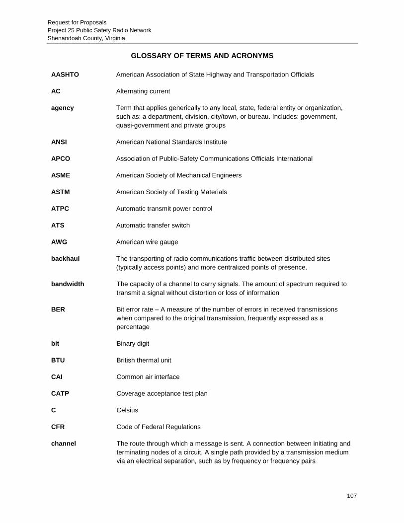
Request for Proposals Project 25 Public Safety Radio Network Shenandoah County, Virginia
107
GLOSSARY OF TERMS AND ACRONYMS AASHTO American Association of State Highway and Transportation Officials
AC Alternating current
agency Term that applies generically to any local, state, federal entity or organization, such as: a department, division, city/town, or bureau. Includes: government, quasi-government and private groups
ANSI American National Standards Institute
APCO Association of Public-Safety Communications Officials International
ASME American Society of Mechanical Engineers
ASTM American Society of Testing Materials
ATPC Automatic transmit power control
ATS Automatic transfer switch
AWG American wire gauge
backhaul The transporting of radio communications traffic between distributed sites (typically access points) and more centralized points of presence.
bandwidth The capacity of a channel to carry signals. The amount of spectrum required to transmit a signal without distortion or loss of information
BER Bit error rate – A measure of the number of errors in received transmissions when compared to the original transmission, frequently expressed as a percentage
bit Binary digit
BTU British thermal unit
CAI Common air interface
CATP Coverage acceptance test plan
C Celsius
CFR Code of Federal Regulations
channel The route through which a message is sent. A connection between initiating and terminating nodes of a circuit. A single path provided by a transmission medium via an electrical separation, such as by frequency or frequency pairs

Request for Proposals Project 25 Public Safety Radio Network Shenandoah County, Virginia
108
communications Information transfer among or between users. In public safety communications, the ability of public safety agencies to talk across agencies
connectivity The complete path between two terminals
conventional A radio system with dedicated, single-purpose channels (can be shared between several users with different operational needs; e.g., fire and police). A user must select the specific channel to be used
coverage The geographic area included within the range of a wireless radio system.
CPC Channel performance criterion
CSI Construction Specifications Institute
CSSI Console subsystem interface
DAQ Delivered audio quality
dB Decibel
dBm Decibel referenced to one milliwatt. (zero dBm)
DC Direct current
digital Radio transmission method that replaces analog systems and transmits its signal in binary 1s and 0s the same as a computer. One major difference is that digital signals do not degrade gradually the way analog signals do as the distance between the transmitter and receiver increases
DS-0 A basic digital signaling rate of 64 kilobits per second (kbps), corresponding to the capacity of one voice-frequency-equivalent channel. The DS-0 rate, and its equivalents E-0 and J-0, form the basis for the digital multiplex transmission hierarchy in telecommunications systems used in North America.
DS-1 Digital Signal, Level 1
DTMF Dual-tone multi-frequency
EIA Electronic Industries Alliance
EMI Electromagnetic interference
encryption The reversible transformation of data from the original (plain text) format to a difficult-to-interpret format as a mechanism for protecting its confidentiality, integrity and sometimes its authenticity. Encryption uses an encryption algorithm and one or more encryption keys.
ERP Effective radiated power

Request for Proposals Project 25 Public Safety Radio Network Shenandoah County, Virginia
109
F Fahrenheit
FAA Federal Aviation Administration
FATP Final acceptance test plan
FCC Federal Communications Commission
FDMA Frequency division multiple access
first responders The first professionals called to an incident or emergency that provides immediate support services during prevention, response, and recovery operations
FM Frequency Modulation – A signal transmission with constant signal strength, where the center frequency varies in proportion to the voice being transmitted. FM signals are not susceptible to most interference sources. Radio systems operating on FM are being replaced by digital systems
frequency The number of cycles or events of a periodic process in a unit of time
frequency bands The spectrum of transmission space where mobile radio systems operate in the United States. They are (from low to high):
High HF 25-29.99 MHz Low VHF 30-50 MHz High VHF 150-174 MHz Low UHF 450-470 MHz UHF TV Sharing 470-512 MHz 700 MHz 764-776 & 7940806 MHz 800 MHz 806-869 MHz 2.4 GHz 4.9 GHz
FRU Field replaceable unit
gateway A device that can transparently interconnect radio audio paths so that agencies can patch into each other's radio channels in real time. This can be done at the baseband level or using IP. A gateway provides interconnection between two networks with different communications protocols
GFI Ground fault interrupter
GHz Gigahertz (1 billion hertz)
GoS Grade of service
GPS Global Positioning System – A U.S. satellite system that lets persons or systems determine their position with extreme accuracy using GPS receivers

Request for Proposals Project 25 Public Safety Radio Network Shenandoah County, Virginia
110
GUI Graphical user interface
HVAC Heating/ventilation/air conditioning
Hz Hertz (same as cycles per second)
ID Identification
IEEE Institute of Electrical and Electronic Engineers
infrastructure Dedicated telecommunications networks; the hardware and software needed to complete and maintain a public safety communications system
interference Extraneous energy, from natural or man-made sources, that impedes the reception of desired RF signals
interoperability The ability of diverse systems and organizations to work together (interoperate). In public safety, the ability of personnel to exchange voice and data communications with staff from other agencies, on demand and in real time
intranet A private computer network that uses Internet technologies to share an organization's information or operational systems with its employees in a secure manner.
IP Internet Protocol
ISSI Inter-RF subsystem interface
kHz kilohertz (1000 hertz)
kVA Kilovolt ampere
kW Kilowatts
LAN Local-area network
LCD Liquid crystal display
LED Light-emitting diode
LMR Land mobile radio – A public or private radio service providing two-way communication, service paging and radio signaling on land.
Mbps Megabits per second (1 million bits per second)
MHSB Monitored hot standby
MHz Megahertz (1 million hertz)

Request for Proposals Project 25 Public Safety Radio Network Shenandoah County, Virginia
111
modem An acronym for modulator/demodulator, which is a device that translates digital signals coming from a computer into analog signals that can be transmitted over standard telephone lines. The modem also translates the analog signals back into digital signals that a computer can understand.
MPE Maximum permissible exposure
MTBF Mean time between failures
NAD National American Datum
NEBS Network Equipment Building System
NEC National Electrical Code
NEMA National Electrical Manufacturers Association
NFPA National Fire Protection Association
NiMH Nickel-metal hydride
NMI Network management interface
NMS Network management system
NMT Network management terminal
NPSPAC National Public Safety Planning Advisory Committee
NRTL Nationally recognized testing laboratory
O.D. Outside diameter
OET Office of Engineering & Technology
OSHA Occupational Safety and Health Administration
OTAP Over-the-air programming
PC Personal computer
P25 or APCO 25 Project 25 – A suite of standards for digital radio communications for use by federal, state/province and local public safety agencies in North America to enable them to communicate with other agencies and mutual-aid response teams in emergencies
psig Pounds per square inch gauge
PTT Push to talk

Request for Proposals Project 25 Public Safety Radio Network Shenandoah County, Virginia
112
Public safety spectrum
Specific bands of frequencies set aside by the FCC for use by public safety agencies. They are:
Low Band (25-50 MHz) VHF High Band (150-174 MHz) 220 MHz Band (220-222 MHz) UHF Band (450-470 MHz) 700 MHz Band (764-776 and 794-806 MHz) 800 MHz Band (806-824 and 851-869 MHz) 4.9 GHz Band
QA/QC Quality assurance/quality control
R56 Motorola Installation Standards and Guidelines for Communication Systems
receiver The component(s) of a radio device that converts the radio waves into audible signals
repeater A special receiver/transmitter combination that receives a signal on one frequency and retransmits a new signal on another frequency, usually within the same frequency band, sometimes referred to as a relay station.
Respondent Any individual or entity bidding on the right to supply products and services in response to this RFP
RF Radio frequency
RFI Radio frequency interference
RFP Request for proposals
RTU Remote terminal unit
SATP Staging acceptance test plan
Selected Respondent
Any individual or entity selected from among all Respondents to supply products and services in response to this RFP
SoR Statement of requirements
spectrum The range of electromagnetic radio frequencies that can be decomposed into frequency components, used in the transmission of sound, data and television
subscriber User/customer on a network.
subscriber unit User’s equipment (usually a mobile or portable radio)
talkgroup An assigned talk path similar to a channel on a conventional system.
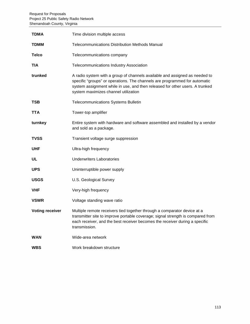
Request for Proposals Project 25 Public Safety Radio Network Shenandoah County, Virginia
113
TDMA Time division multiple access
TDMM Telecommunications Distribution Methods Manual
Telco Telecommunications company
TIA Telecommunications Industry Association
trunked A radio system with a group of channels available and assigned as needed to specific “groups” or operations. The channels are programmed for automatic system assignment while in use, and then released for other users. A trunked system maximizes channel utilization
TSB Telecommunications Systems Bulletin
TTA Tower-top amplifier
turnkey Entire system with hardware and software assembled and installed by a vendor and sold as a package.
TVSS Transient voltage surge suppression
UHF Ultra-high frequency
UL Underwriters Laboratories
UPS Uninterruptible power supply
USGS U.S. Geological Survey
VHF Very-high frequency
VSWR Voltage standing wave ratio
Voting receiver Multiple remote receivers tied together through a comparator device at a transmitter site to improve portable coverage; signal strength is compared from each receiver, and the best receiver becomes the receiver during a specific transmission.
WAN Wide-area network
WBS Work breakdown structure

Request for Proposals Project 25 Public Safety Radio Network Shenandoah County, Virginia
114
APPENDIX A: PROPOSAL FORM

OFFICIAL PROPOSAL FORM
The undersigned proposer agrees, if awarded a contract by the Shenandoah
County, VA to provide a P25 Public Safety Radio System as specified in accordance
with the foregoing Request for Proposal for the price specified below.
THIS PROPOSAL ADDRESSES THE FOLLOWING NETWORK
COMPONENTS (check each as applicable)
P25 Radio System ____ Tone and Voice Paging System ____ Dispatch Console System ____ Network Management ____ Digital Microwave Network ____ Site Development ____ Towers ____ Shelters ____ Generators ____ P25 Subscriber Units ____ Tone and voice pagers ____
TOTAL PROPOSAL PRICE
TOTAL BASE PROPOSAL AMOUNT………………………..$_____________
NAME OF PROPOSER (type or print)
ADDRESS
AUTHORIZED SIGNATURE
AFFIX CORPORATE _________________________________ SEAL HERE PRINT NAME AND TITLE OF SIGNER (If proposer is a corporation)
___(_____)________________________ AREA CODE & TELEPHONE ___(_____)________________________ FAX NUMBER

Proposer is (check one):
_______Corporation incorporated in the State of ____________
_______General Partnership
_______Limited Partnership
_______Sole Proprietorship
_______Other (specify) ___________________________

Request for Proposals Project 25 Public Safety Radio Network Shenandoah County, Virginia
117
APPENDIX B: PROPOSAL PRICING FORMS

Appendix B - Pricing WorkbookShenandoah County, VA
Pricing Workbook Instructions and Guidelines
Detailed line‐item pricing for all material and services is requested. Respondents may add lines and columns to accommodate the in‐depthpricing detail requested.
A separate worksheet should be generated for each tower site and equipment location, including, but not limited tothe core controllers, simulcast cell controllers, each site where RF equipment is located, and dispatch locations
Antenna systems for LMR and microwave systems should be listed on the worksheet page for that site. Additional lines may be inserted as needed.
Accessories available for mobile and portable radios should be listed. Separate catalogs and price lists for accessories are requested.
The 15 year Cost of Ownership should include all services available from the respondent.
This Pricing Workbook has been developed to foster conformity of respondents' pricing proposals and aid in evaluation of these

Appendix B - Pricing WorkbookShenandoah County, VA
Description Total
RFP Requirements
P25 Radio Communications System $0.00
Remote Site Equipment $0.00
Network Management Systems $0.00
Dispatch Console System $0.00
Microwave Network $0.00
Remote Site Facilities $0.00
Portable Radio Type 1 - No Keypad $0.00
Portable Radio Type 2 - Limited Keypad $0.00
Portable Radio Type 3 - Full Keypad $0.00
Single Band Mobile Radio - Dash Mount $0.00
Single Band Mobile Radio - Remote Mount $0.00
Desktop/Remote Consolette Stations $0.00
15 Year Cost of Ownership $0.00
Additional Costs/Discounts (list separately) $0.00
$0.00
TOTAL PROPOSAL COST $0.00
RFP OPTIONS
Radio Communications System $0.00
Microwave Network $0.00
Subscriber Equipment $0.00
RESPONDENTS SHALL COMPLETE SPEPARATE PRICING FORMS
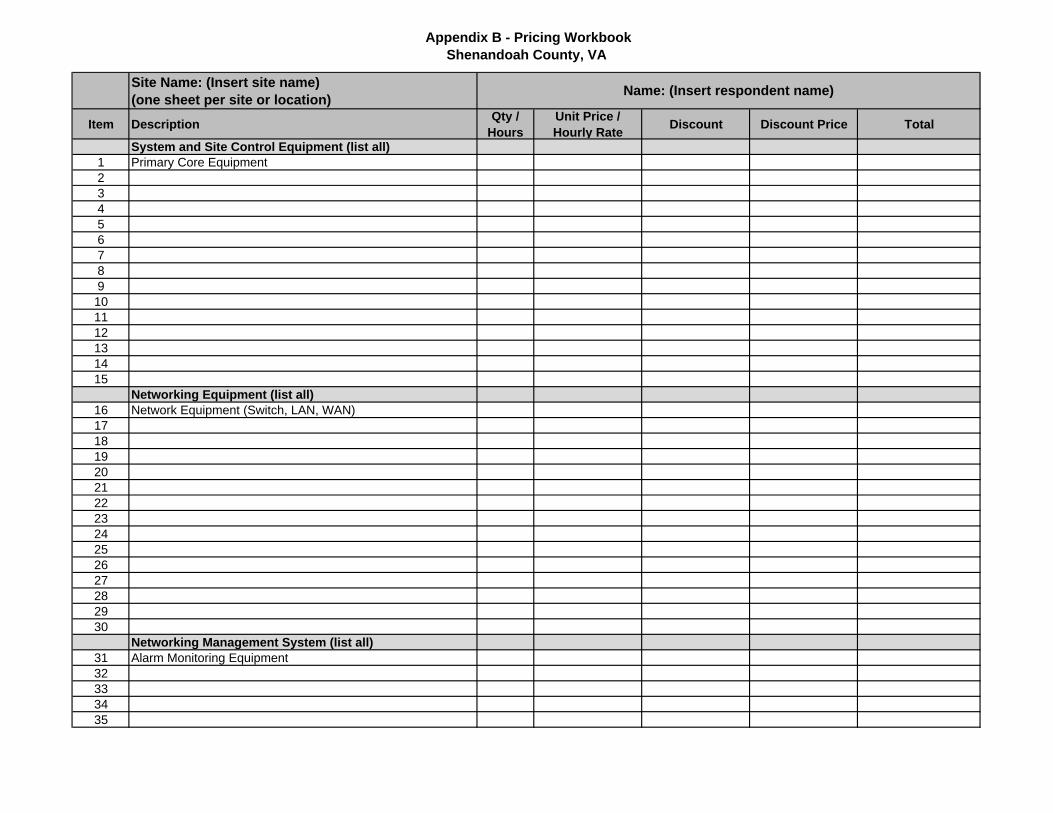
Appendix B - Pricing WorkbookShenandoah County, VA
Site Name: (Insert site name)(one sheet per site or location)
Item Description Qty / Hours
Unit Price / Hourly Rate Discount Discount Price Total
System and Site Control Equipment (list all)1 Primary Core Equipment23456789101112131415
Networking Equipment (list all)16 Network Equipment (Switch, LAN, WAN) 1718192021222324252627282930
Networking Management System (list all)31 Alarm Monitoring Equipment32333435
Name: (Insert respondent name)

Appendix B - Pricing WorkbookShenandoah County, VA
Item Description Qty / Hours
Unit Price / Hourly Rate Discount Discount Price Total
36373839404142434445
Miscellaneous 46 Simulcast Equipment (provide details)47 Receiver Voting Equipment (provide details)48 Over the air programming (OTAP)49 Over the air rekeying (OTAR)50 GPS Location515253545556 Other (list all)575859606162636465
Engineering & Services66 Project Management67 System Engineering68 System Staging69 Coverage and Acceptance Testing70 Documentation71 Other services (list all)727374

Appendix B - Pricing WorkbookShenandoah County, VA
Item Description Qty / Hours
Unit Price / Hourly Rate Discount Discount Price Total
75Training
76 Operational training77 User training 78 System manager training 79 Maintenance training 80 Other (list all)8182838485
Warranty & Maintenance86 1 year total system warranty after acceptance87 Year #288 Year #389 Year #490 Year #591 Other (list all)92939495
TOTAL $0.00

Appendix B - Pricing WorkbookShenandoah County, VA
Site Name: (Insert site name)(one sheet per site or location)
Item Description Qty / Hours
Unit Price / Hourly Rate Discount Discount Price Total
Networking Equipment (list all)123456789101112131415
Site Equipment16 Repeaters17 Transmit combiner18 Receiver multicoupler19 Receiver tower top preamplifier20 Antenna system21 Software (list all)22 Other (list all)23242526272829303132333435
Miscellaneous 36 Simulcast Equipment (provide details)37 Receiver Voting Equipment (provide details)38 Other (list all)
Name: (Insert respondent name)

Appendix B - Pricing WorkbookShenandoah County, VA
Item Description Qty / Hours
Unit Price / Hourly Rate Discount Discount Price Total
39404142434445
Engineering & Services46 Project management47 System Engineering48 System Staging49 Acceptance Testing50 Documentation51 Other services (list all)52535455
TOTAL $0.00
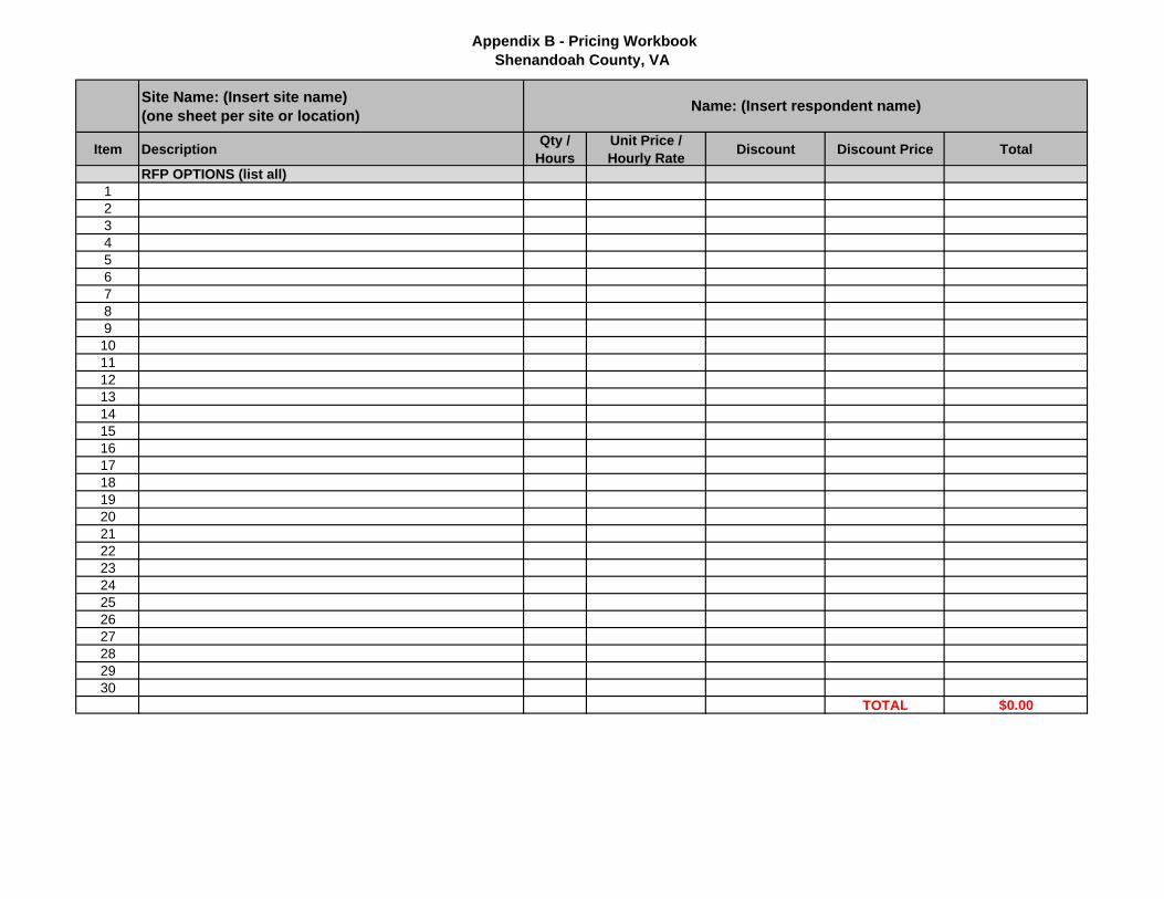
Appendix B - Pricing WorkbookShenandoah County, VA
Site Name: (Insert site name)(one sheet per site or location)
Item Description Qty / Hours
Unit Price / Hourly Rate Discount Discount Price Total
RFP OPTIONS (list all)123456789101112131415161718192021222324252627282930
TOTAL $0.00
Name: (Insert respondent name)

Appendix B - Pricing WorkbookShenandoah County, VA
Network Management SystemSite Name: (Insert site name)
Item Description Qty / Hours
Unit Price / Hourly Rate Discount Discount Price Total
1 Network Management System Equipment (Radio)2 Network Management System Equipment (Microwave)3456789
1011121314151617181920
Engineering & Services21 Project Management22 System Engineering23 System Staging24 Installation25 Acceptance Testing26 Documentation27 Other Services (list all)28293031
Name: (Insert respondent name)

Appendix B - Pricing WorkbookShenandoah County, VA
Network Management SystemSite Name: (Insert site name)
Item Description Qty / Hours
Unit Price / Hourly Rate Discount Discount Price Total
Name: (Insert respondent name)
Training (List all)3132333435
Support & Maintenance After First Year Warranty37 Year 238 Year 339 Year 440 Year 541 Other (list all)4445
TOTAL $0.00

Appendix B - Pricing WorkbookShenandoah County, VA
Location Name: (Insert location name)(one page per console site location)
Item Description Qty / Hours
Unit Price / Hourly Rate Discount Discount Price Total
Dispatch Console System1 Common electronics equipment (list all)2 Network equipment3 Auxiliary I/O interfaces4 Conventional channel gateways5 Console Operator Position6 LCD display7 Footswitch8 Headset9 Software10 Logging recorder or interface11 Spare equipment (list all)12 Other (list all)1314151617181920
Engineering & Services21 Project Management22 System Engineering23 System Staging24 Acceptance Testing25 Documentation26 Other Services (list all)27282930
Training (List all)3132333435
Warranty & Maintenance36 1 year total system warranty after acceptance
Name: (Insert respondent name)

Appendix B - Pricing WorkbookShenandoah County, VA
Location Name: (Insert location name)(one page per console site location)
Item Description Qty / Hours
Unit Price / Hourly Rate Discount Discount Price Total
Name: (Insert respondent name)
37 Year #238 Year #339 Year #440 Year #541 Other (list all)42434445
TOTAL $0.00

Appendix B - Pricing WorkbookShenandoah County, VA
Hop Name: (Insert hop name)Site Name: (Insert site name)(one page per new or upgraded hop)
Item Description Qty / Hours
Unit Price / Hourly Rate Discount Discount Price Total
Site A - Terminal Equipment1 Microwave radio2 Multiplex equipment3 Microwave antenna system equipment (provide details)4 DC power system and power supply5 Programming6 Physical path surveys7 Alarm and control8 Spare equipment (list all)9 Other (list all)101112131415161718192021
Site B - Terminal Equipment22 Microwave radio23 Multiplex equipment24 Antenna system25 Power supply and battery subsystem26 Programming27 Alarm and control28 Spare equipment (list all)29 Other (list all)303132333435363738
Name: (Insert respondent name)

Appendix B - Pricing WorkbookShenandoah County, VA
Hop Name: (Insert hop name)Site Name: (Insert site name)(one page per new or upgraded hop)
Item Description Qty / Hours
Unit Price / Hourly Rate Discount Discount Price Total
Name: (Insert respondent name)
394041
Networking Equipment (list all)42434445464748495051
Networking Management Equipment (list all)52535455565758596061
Engineering & Services62 Project Management63 Path Engineering64 System Staging65 Acceptance Testing66 Documentation67 Other Services (list all)68697071
Training (List all)727374

Appendix B - Pricing WorkbookShenandoah County, VA
Hop Name: (Insert hop name)Site Name: (Insert site name)(one page per new or upgraded hop)
Item Description Qty / Hours
Unit Price / Hourly Rate Discount Discount Price Total
Name: (Insert respondent name)
7576
Warranty & Maintenance77 1 year total system warranty after acceptance78 Other (list all)798081
TOTAL $0.00

Appendix B - Pricing WorkbookShenandoah County, VA
Hop Name: (Insert hop name)(one sheet per hop (as applicable)) Name: (Insert respondent name)
Item Description Qty / Hours
Unit Price / Hourly Rate Discount Discount Price Total
RFP OPTIONS (list all)123456789101112131415161718192021222324252627282930
TOTAL $0.00

Appendix B - Pricing WorkbookShenandoah County, VA
Remote Site FacilitiesSite Name: (Insert tower name)(one page per site location)
Name: (Insert respondent name)
Item Description Qty / Hours
Unit Price / Hourly Rate Discount Discount Price Total
Remote Site Facilities1 Tower modifications or new tower (provide details)2 Tower analysis3 Site preparation and finishing 4 Equipment shelter5 Emergency generator and fuel system 6 Automatic Transfer switch7 Alarms and security8 Grounding and surge protection9 Spare equipment (list all)10 Other (list all, including RFP OPTIONS)1112131415161718
Engineering & Services19 Project Management20 System Engineering21 System Staging22 Acceptance Testing23 Documentation24 Other Services (list all)25262728
Training (List all)29303132
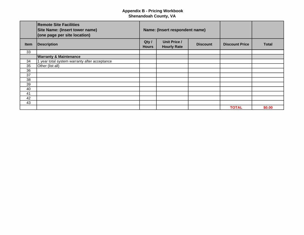
Appendix B - Pricing WorkbookShenandoah County, VA
Remote Site FacilitiesSite Name: (Insert tower name)(one page per site location)
Name: (Insert respondent name)
Item Description Qty / Hours
Unit Price / Hourly Rate Discount Discount Price Total
33Warranty & Maintenance
34 1 year total system warranty after acceptance35 Other (list all)3637383940414243
TOTAL $0.00

Appendix B - Pricing WorkbookShenandoah County, VA
Portable Radio Type 1 - No Keypad
Item Description Qty / Hours
Unit Price / Hourly Rate Discount Discount Price Total
1 Portable Radio Type 1 - No Keypad2 Digital Operation3 P25 Trunking Operation4 TDMA5 Antenna options (list all)6 Data Operation7 GPS8 OTAP9 AES Encryption10 Bluetooth11 Intrinsically safe radio12 Documentation13 Software14
Accessories:15 Battery, NiMH16 Battery, L-ion17 High capacity battery18 Intrinsically safe battery19 Headset, wired20 Headset, wireless21 Remote Speaker Mic22 Remote speaker Mic, with antenna23 Carry Cases, belt clip options (list all)24 Single Unit Charger25 Multi-Unit Charger with Display26 Multi-Unit Charger without Display27 Vehicular Charger28 Data cables (list all)29
Engineering & Services30 Programming & Delivery313233343536373839
Training4041424344
Support & MaintenanceAfter First Year Warranty
45 Year 246 Year 347 Year 448 Year 549
Preventive Maintenance (Per Year)50 Every 6 months51 Every 1 year52 Every 2 years53545556 Other (list all)5758
TOTAL $0.00
Name: (Insert respondent name)

Appendix B - Pricing WorkbookShenandoah County, VA
Portable Radio Type 2 - Limited Keypad
Item Description Qty / Hours
Unit Price / Hourly Rate Discount Discount Price Total
1 Portable Radio Type 2 - Limited Keypad2 Digital Operation3 P25 Trunking Operation4 TDMA5 Antenna options (list all)6 Data Operation7 GPS8 OTAP9 AES Encryption10 Bluetooth11 Intrinsically safe radio12 Documentation13 Software14
Accessories:15 Battery, NiMH16 Battery, L-ion17 High capacity battery18 Intrinsically safe battery19 Headset, wired20 Headset, wireless21 Remote Speaker Mic22 Remote speaker Mic, with antenna23 Carry Cases, belt clip options (list all)24 Single Unit Charger25 Multi-Unit Charger with Display26 Multi-Unit Charger without Display27 Vehicular Charger28 Data cables (list all)29
Engineering & Services30 Programming & Delivery313233343536373839
Training4041424344
Support & MaintenanceAfter First Year Warranty
45 Year 246 Year 347 Year 448 Year 549
Preventive Maintenance (Per Year)50 Every 6 months51 Every 1 year52 Every 2 years53545556 Other (list all)5758
TOTAL $0.00
Name: (Insert respondent name)

Appendix B - Pricing WorkbookShenandoah County, VA
Portable Radio Type 3 - Full Keypad
Item Description Qty / Hours
Unit Price / Hourly Rate Discount Discount Price Total
1 Portable Radio Type 3 - Full Keypad2 Digital Operation3 P25 Trunking Operation4 TDMA5 Antenna options (list all)6 Data Operation7 GPS8 OTAP9 AES Encryption10 Bluetooth11 Intrinsically safe radio12 Documentation13 Software14
Accessories:15 Battery, NiMH16 Battery, L-ion17 High capacity battery18 Intrinsically safe battery19 Headset, wired20 Headset, wireless21 Remote Speaker Mic22 Remote speaker Mic, with antenna23 Carry Cases, belt clip options (list all)24 Single Unit Charger25 Multi-Unit Charger with Display26 Multi-Unit Charger without Display27 Vehicular Charger28 Data cables (list all)29
Engineering & Services30 Programming & Delivery313233343536373839
Training4041424344
Support & MaintenanceAfter First Year Warranty
45 Year 246 Year 347 Year 448 Year 549
Preventive Maintenance (Per Year)50 Every 6 months51 Every 1 year52 Every 2 years53545556 Other (list all)5758
TOTAL $0.00
Name: (Insert respondent name)

Appendix B - Pricing WorkbookShenandoah County, VA
Portable Radio - Multiband
Item Description Qty / Hours
Unit Price / Hourly Rate Discount Discount Price Total
1 Portable Radio - Multiband2 Digital Operation3 P25 Trunking Operation4 TDMA5 Antenna options (list all)6 Data Operation7 GPS8 OTAP9 AES Encryption10 Bluetooth11 Intrinsically safe radio12 Documentation13 Software14
Accessories:15 Battery, NiMH16 Battery, L-ion17 High capacity battery18 Intrinsically safe battery19 Headset, wired20 Headset, wireless21 Remote Speaker Mic22 Remote speaker Mic, with antenna23 Carry Cases, belt clip options (list all)24 Single Unit Charger25 Multi-Unit Charger with Display26 Multi-Unit Charger without Display27 Vehicular Charger28 Data cables (list all)29
Engineering & Services30 Programming & Delivery313233343536373839
Training4041424344
Support & MaintenanceAfter First Year Warranty
45 Year 246 Year 347 Year 448 Year 549
Preventive Maintenance (Per Year)50 Every 6 months51 Every 1 year52 Every 2 years53545556 Other (list all)5758
TOTAL $0.00
Name: (Insert respondent name)
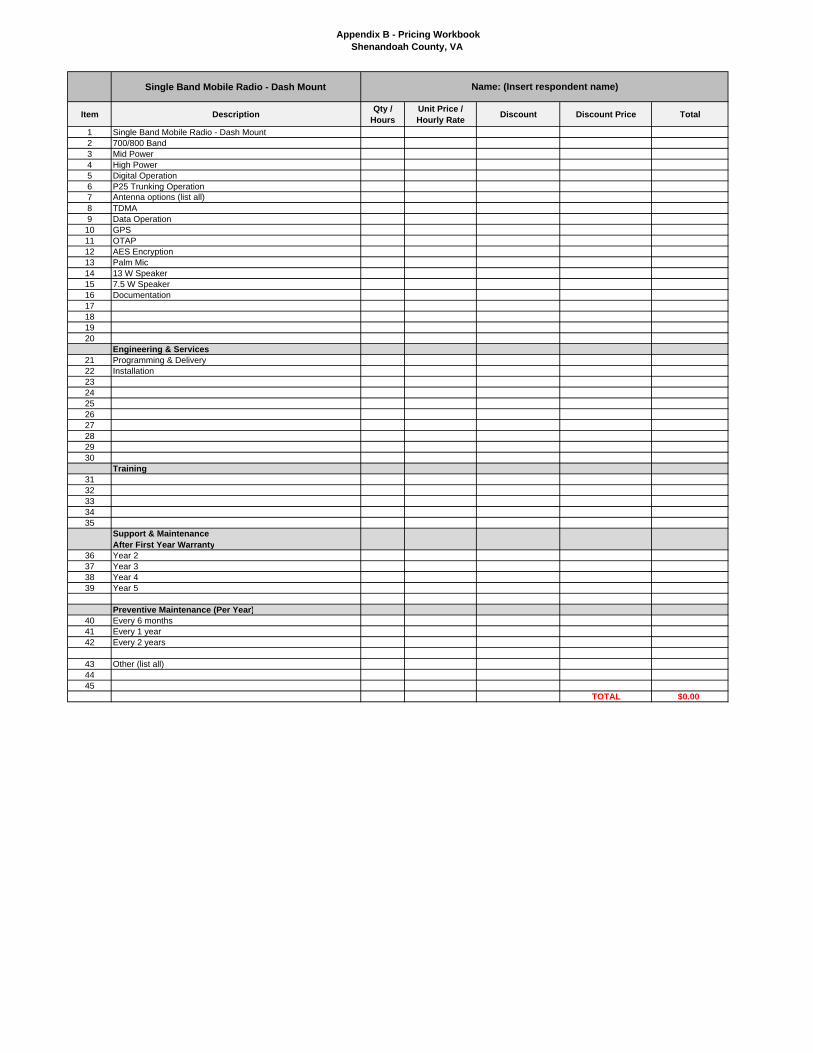
Appendix B - Pricing WorkbookShenandoah County, VA
Single Band Mobile Radio - Dash Mount
Item Description Qty / Hours
Unit Price / Hourly Rate Discount Discount Price Total
1 Single Band Mobile Radio - Dash Mount2 700/800 Band3 Mid Power4 High Power5 Digital Operation6 P25 Trunking Operation7 Antenna options (list all)8 TDMA9 Data Operation
10 GPS11 OTAP12 AES Encryption13 Palm Mic14 13 W Speaker15 7.5 W Speaker16 Documentation17181920
Engineering & Services21 Programming & Delivery22 Installation2324252627282930
Training3132333435
Support & MaintenanceAfter First Year Warranty
36 Year 237 Year 338 Year 439 Year 5
Preventive Maintenance (Per Year)40 Every 6 months41 Every 1 year42 Every 2 years
43 Other (list all)4445
TOTAL $0.00
Name: (Insert respondent name)

Appendix B - Pricing WorkbookShenandoah County, VA
Single Band Mobile Radio - Remote Mount
Item Description Qty / Hours
Unit Price / Hourly Rate Discount Discount Price Total
1 Single Band Mobile Radio - Remote Mount2 700/800 Band3 Mid Power4 High Power5 Digital Operation6 P25 Trunking Operation7 Antenna options (list all)8 TDMA9 Data Operation10 GPS11 OTAP12 AES Encryption13 Palm Mic14 13 W Speaker15 7.5 W Speaker16 Remote Mount Cable (list all)17 Remote speaker mic (list all)18 Power cables (list all)19 Documentation20 Adapters (list all)21 Other (list all)22
Engineering & Services23 Programming & Delivery24 Installation2526272829303132
Training3334353637
Support & MaintenanceAfter First Year Warranty
38 Year 239 Year 340 Year 441 Year 542
Preventive Maintenance (Per Year)43 Every 6 months44 Every 1 year45 Every 2 years4647 Other (list all)4849
TOTAL $0.00
Name: (Insert respondent name)

Appendix B - Pricing WorkbookShenandoah County, VA
Desktop/Remote Consolette Stations
Item Description Qty / Hours
Unit Price / Hourly Rate Discount Discount Price Total
1234567891011
Digital Desktop Remote Control System121314151617
Control Station Antenna System18192021222324
Engineering & Services25 Programming & Delivery26 Installation27282930
Training3132333435
Support & MaintenanceAfter First Year Warranty
36 Year 237 Year 338 Year 439 Year 5
Preventive Maintenance (Per Year)40 Every 6 months41 Every 1 year42 Every 2 years
43 Other (list all)4445
TOTAL $0.00
Name: (Insert respondent name)

Appendix B - Pricing WorkbookShenandoah County, VA
Single Band Mobile Radio - Remote Mount
Item Description Qty / Hours
Unit Price / Hourly Rate Discount Discount Price Total
1 Paging Infrastructure2 Pagers (list all options)3 Software4 Documentation5 Other (list all)678910111213141516171819202122
Engineering & Services23 Programming & Delivery24 Installation252627282930
TOTAL $0.00
Name: (Insert respondent name)

Appendix B - Pricing WorkbookShenandoah County, VA
Recommended Spares and Test Equipment
Item Description Qty / Hours
Unit Price / Hourly Rate Discount Discount Price Total
1 Recommended Spare Parts for Main P25 System Core
2 Recommended Spare Parts for Main P25 System Simulcast System
3 Recommended Spare Parts for Paging System4 Recommended Spare Parts for Console System
5 Recommended Spare Parts for Network Management System
6 Recommended Spare Parts for Microwave System
7 Recommended Spare Parts for Conventional Interoperabilty Overlay System
89
1011121314151617181920
Engineering & Services (as applicable)21 Programming & Delivery22 Installation232425
TOTAL $0.00
Name: (Insert respondent name)

Appendix B - Pricing WorkbookShenandoah County, VA
Total 15 Year Cost of Ownership
Item Service Description Year 1 (Included with Warranty) Year 2 Year 3 Year 4 Year 5 Year 6
1 P25 System Upgrade Agreement - Hardware and Software2 Remote Technical Support3 System Monitoring4 System Dispatch Service5 Field Technical Support6 Equipment Annual Preventive Maintenance7 Equipment Parts Replacement8 Microwave Service9 Disaster Preparedness Services10 Disaster Recovery Services
11 Security Update Service: inlcudes antivirus, security patches.
12 Other13141516171819 TOTAL
*Note: Year 1 begins upon system acceptance.

Appendix B - Pricing WorkbookShenandoah County, VA
Year 7 Year 8 Year 9 Year 10 Year 11 Year 12 Year 13 Year 14 Year 15
Name: (Insert respondent name)

Request for Proposals Project 25 Public Safety Radio Network Shenandoah County, Virginia
147
APPENDIX C: POTENTIAL CANDIDATE TOWER SITES
Address City St Zip Site Latitude Site Longitude 67 Breckenridge Road Strasburg VA 22657 39.00330999 -78.37764012 168 Quarry Lane Strasburg VA 22657 39.01061997 -78.32937996 1181 Mount Olive Road Toms Brook VA 22660 38.96604 -78.44195988 3075 South Ox Road Edinburg VA 22824 38.84163003 -78.56781984 192 Short Run Lane Mt. Jackson VA 22842 38.77104 -78.630776 124 South Main Street Edinburg VA 22824 38.82152997 -78.56624988 495 Tussing Lane Mt. Jackson VA 22842 38.77972222 -78.77613889 12419 Senedo Road Mt. Jackson VA 22842 38.809755 -78.713582 100 Reliance Road Middletown VA 22645 39.02820003 -78.27109992 326 Banks Fort Road Strasburg VA 22657 38.99180997 -78.36082992 157 Leigh Lane Basye VA 22811 38.81067003 -78.76834992 6827 Orkney Grade Mt. Jackson VA 22842 38.77225002 -78.73311096 15250 Senedo Road Edinburg VA 22824 38.83875 -78.67527778 329 Earl Sine Road Edinburg VA 22824 38.87652996 -78.63627816 3370 Smith Creek Road New Market VA 22844 38.64517002 -78.63672204 15225 Gold Nugget Drive Fulks Run VA 22830 38.67532803 -78.93563292 1507 Cottontown Road Strasburg VA 22657 39.065625 -78.382653 2844 Wardensville Pike Star Tannery VA 22654 39.10115403 -78.49503396 1507 Cottontown Road Strasburg VA 22657 39.0655 -78.383241 6194 Woodstock Tower Road Fort Valley VA 22652 38.84774004 -78.41814984 200 Brill Road Star Tannery VA 22654 39.09630996 -78.45033996 3557 Old Valley Pike New Market VA 22844 38.67900003 -78.65807004 212 Piccadilly Street Edinburg VA 22824 38.823045 -78.565951 460 Harman Road Maurertown VA 22644 38.931256 -78.481106 3557 Old Valley Pike New Market VA 22844 38.67900003 -78.65807004
Note: The towers all have fiber optic network connectivity.

Request for Proposals Project 25 Public Safety Radio Network Shenandoah County, Virginia
148
APPENDIX D: COMPLIANCE MATRIX

RFP for P25 Public Safety Radio System Shenandoah County, VA Appendix DCompliance Matrix
RFP Section Description
Respondent's Statement of Compliance_____________________________Select One Choice: 1) Comply 2) Comply with Clarification 3) Exception
Respondent's Clarifications and Comments
1.0 Project Overview1.1 Introduction1.2 Background1.2.1 Shenandoah County Overview1.3 RFP Overview1.4 Project Summary1.5 Proposals Desired1.5.1 Systems1.5.2 Services1.6 Quality Assurance and Coordination1.6.1 Standards and Guidelines1.6.2 P25 Standard Compliance1.6.3 Frequency Coordination and Licensing1.6.4 Federal Aviation Administration (if applicable)1.6.5 Project Management1.6.6 Project Meetings1.6.7 Project Staffing1.6.8 Quality Assurance/Quality Control Program1.7 Delivery, Storage and Handling1.8 Project Submittals1.8.1 Proposal1.8.2 Preliminary Design (45 days after contract award)1.8.3 Final Design (90 days after contract award)1.8.4 System Staging, Delivery and Installation1.8.5 Final System Acceptance2.0 Instructions to Respondents2.1 Overview2.2 Pre-Proposal Conference2.3 Schedule of Events
Page 1 of 5

RFP for P25 Public Safety Radio System Shenandoah County, VA Appendix DCompliance Matrix
RFP Section Description
Respondent's Statement of Compliance_____________________________Select One Choice: 1) Comply 2) Comply with Clarification 3) Exception
Respondent's Clarifications and Comments
2.4 Proposal Format2.5 Evaluation2.6 Addenda to the Contract2.7 Award of Contract3 Radio Communications System Requirements3.1. Overview3.2. Interoperability/P25 Statement of Requirements3.3. System Configuration3.3.1. Redundancy and Survivability3.3.2. Expansion3.3.3. Grade of Service – Trunked System3.4. Site Selection3.5. Coverage3.5.1. Coverage Maps3.5.2. Map Criteria3.5.3. Coverage Model3.5.4. TIA TSB-88 – Annex E User Choices3.6. Site Equipment3.6.1. Overview3.6.2. System and Site Control Equipment3.6.3. Simulcast Equipment3.6.4. Receiver Voting3.6.5. Base Station Equipment3.6.6. Antenna Systems3.6.7. Antenna Installation3.6.8. Removal of Existing Infrastructure and Equipment3.7. Network Management System3.7.1. Network Management Terminal3.7.2. Remote Terminal Units
Page 2 of 5

RFP for P25 Public Safety Radio System Shenandoah County, VA Appendix DCompliance Matrix
RFP Section Description
Respondent's Statement of Compliance_____________________________Select One Choice: 1) Comply 2) Comply with Clarification 3) Exception
Respondent's Clarifications and Comments
3.8. Shared Switch – Option3.9. Mobile Data – Option3.10. Backup Consolettes – Option4 Backhaul Network4.1. Overview4.2. Digital Microwave Network4.2.1. Requirements4.2.2. Microwave Engineering5 Site Development5.1. General5.2. Towers5.3. Shelters5.4. Generator and Automatic Transfer Switch5.4.1. Diesel Generator5.4.2. Automatic Transfer Switch5.4.3. Diesel Fuel System5.5 DC Power5.6 Site Preparation5.7 Fencing6 Dispatch Consoles6.1. General Requirements and Features6.2. Trunked Requirements6.3. Conventional Requirements6.4. Paging Requirements6.5. Systems Integration6.6. Logging Recorder6.7. Operator Position Equipment6.8. Common Electronics Equipment7 Warranty, Maintenance, and Support
Page 3 of 5

RFP for P25 Public Safety Radio System Shenandoah County, VA Appendix DCompliance Matrix
RFP Section Description
Respondent's Statement of Compliance_____________________________Select One Choice: 1) Comply 2) Comply with Clarification 3) Exception
Respondent's Clarifications and Comments
7.1. Warranty7.2. Maintenance7.2.1. General Requirements7.2.2. Maintenance Standards7.3. Parts Availability7.4. Spare Equipment7.5. Lifecycle Cost – Option8 System Implementation, Test and Acceptance8.1. General8.2. Cutover Plan8.3. Staging8.4. System Installation8.5. Coverage Testing (Radio System Respondents Only)8.6. 30-day Operational Test8.7. Training8.8. Final Acceptance Testing8.9. As-Built Documentation8.10. System Acceptance9 Subscriber Equipment9.1. Overview9.2. General Requirements9.2.1 Portable Radios9.2.2 Mobile Radios/Control Stations9.2.3 Fleet Mapping9.3 Subscriber Warranty and Maintainence9.3.1 Subscriber Warranty9.3.2 Subscriber Maintenance10 County Terms and ConditionsGlossary of Terms and Acronyms
Page 4 of 5

RFP for P25 Public Safety Radio System Shenandoah County, VA Appendix DCompliance Matrix
RFP Section Description
Respondent's Statement of Compliance_____________________________Select One Choice: 1) Comply 2) Comply with Clarification 3) Exception
Respondent's Clarifications and Comments
Appendix A - Proposal FormAppendix B - Proposal Pricing FormsAppendix C - Candidate Site ListAppendix D - Compliance MatrixAppendix E - Coverage Requirements Map
Page 5 of 5

Request for Proposals Project 25 Public Safety Radio Network Shenandoah County, Virginia
154
APPENDIX E: COVERAGE REQUIREMENTS MAP The following map indicates where 6-dB in-building coverage for portables is required.

Request for Proposals Project 25 Public Safety Radio Network Shenandoah County, Virginia
155
APPENDIX F: LOCAL TELECOMMUNICATIONS PROVIDER FIBER-OPTIC NETWORK
Note: Green is buried fiber, blue is aerial fiber, Magenta is shared fiber