
Sheet Meatal Failure
10
Y. Park 1 J. S. Colton Professor, Fellow ASME The George W. Woodruff School of Mechanical Engineering, Georgia Institute of Technology, Atlanta, GA 30332-0405 Failure Analysis of Rapid Prototyped Tooling in Sheet Metal Forming—V-Die Bending The demand for rapid, low-cost die fabrication and modification technology is greater than ever in the sheet metal forming industry. One category of rapid tooling technology involves the use of advanced polymers and composite materials to fabricate metal forming dies. However, due to their lack of strength as compared to conventional metal dies, the use of polymer dies is often limited to prototype or short-run production. In addition, because the mechanisms by which they fail are not fully understood, the dies are designed on the basis of experience and intuition. This study investigates the failure of V-bending dies fabricated from an easy-to-machine, polyurethane-based, composite board stock. Based on the mechanical behavior of the die material, several failure criteria are pro- posed to predict die failure mode and the corresponding die life. Both computational and experimental methods are employed to assess the accuracy of the criteria and to identify the dominant process parameters in V-die bending. @DOI: 10.1115/1.1828053# 1 Introduction Sheet metal forming is one of the most commonly practiced fabrication processes in industry. Throughout the years, the sheet metal forming industry experienced technological advances that allowed the production of complex parts. However, the advances in die design and fabrication progressed at a much slower rate, and they still depend heavily on trial-and-error and the experi- ences of skilled workers. One trend evident in today’s manufacturing industry is the growing demand for faster turn-around times and a more efficient means of producing prototype and short-run tooling. In most manufacturing industries, prototype fabrication is a crucial step in the development or modification of a product before proceeding to large-scale production. It allows an early assessment of the part during the design stage, and enables a reduction in the product development time. Also, the trend of customer needs is heading towards low-volume production of diverse products. This trend gave rise to the development of rapid prototyping ~RP! and tool- ing ~RT! technologies. Many research efforts have been dedicated to developing RT techniques for sheet metal forming, pioneered by Nakagawa @2# and Dickens @3#. Du et al. @4# and Cheah et al. @5# investigated various direct and indirect RT techniques, which use advanced computer-aided techniques and computer-controlled machines to produce nonferrous tooling. The authors performed and made comparisons among three approaches—selective laser sintering ~SLS!, stereolithography ~SLA!, and high-speed computer nu- merical controlled ~CNC! milling—in terms of tool life and tool development cost and time, which can serve as a criteria for the selection of a RT process. Walczyk and Hardt @6# developed the profiled edge lamination ~PEL! tooling method, in which contoured-edge lamination members are stacked side-by-side and reoriented to a vertical plane, solving the stair-stepped surface problem. Compared to CNC machining, the PEL method elimi- nates most tooling accessibility problems, reduces limitations on die geometry, and allows for faster fabrication. One of the techniques that has been drawing attention from industry recently is the application of aluminum trihydrate~ATH!- filled polyurethane as a tooling material. An example is Ren Shape™ 5166. The foremost advantage is its good machinability, which allows a significant reduction in the die fabrication time. The ATH-filled polyurethane also exhibits high compressive strength and impact resistance among its class, which helps the die resist deformation and retain sharp edges. Despite their advantages in terms of lead time and cost, poly- mer composite dies have several shortcomings. Due to their lack of strength as compared to conventional die materials, the life of polymer composite dies is an issue. The sectors of industry that use these dies have been hindered by their premature failure—that is, the dies fail before the desired number of sheet metal parts are produced. Moreover, because the mechanisms by which they fail are not fully understood, in most cases dies still are designed on the basis of experience and intuition. In practice, the polymer composite tool manufacturers actually depend on the design stan- dards and guidelines established for metal dies. Unlike sheet metal forming, where die failure is not much of an issue because the stiffness of the formed parts is significantly lower than that of the die, a number of studies have been geared toward the failure analysis of the dies in bulk metal forming. Most of them involve computer-aided techniques with the common goal of reducing development time and cost by replacing full-scale process trials with computational simulations. Numerical simula- tion and modeling of metal forming processes, based on the knowledge of underlying process mechanics and validated by ex- perimental results, are powerful tools for optimizing process pa- rameters @7#. A number of studies estimated the mechanical fa- tigue life of cold forging or extrusion dies @8–11#. However, studies on the failure of sheet metal forming dies have been rather limited as these often are assumed to have infinite lives, which is not necessarily true for polymer composite dies. This paper proposes a fracture mechanics and fatigue-based method to determine the failure mode of a 90 deg V-bending die fabricated from a polymer composite and to determine the fatigue life of the die if the die is predicted to fail by fatigue. The research used machinable ATH-filled polyurethane board stock, known as Ren Shape™ 5166 by Vantico Inc. In the case of fatigue failure, four representative fatigue models were investigated to determine the most accurate life estimation criterion. Subsequently, finite element analyses ~FEA! were performed to simulate the V-die bending process and to obtain the stress–strain response. Experi- ments were performed to verify the proposed die failure mode and life prediction method as well as the FEA results. Finally, a para- 1 Currently at the Department of Industrial and Manufacturing, FAMU-FSU College of Engineering, Tallahassee, FL. Contributed by the Manufacturing Engineering Division for publication in the JOURNAL OF MANUFACTURING SCIENCE AND ENGINEERING. Manuscript received August 11, 2003; revised February 11, 2004. Associate Editor: J. Cao. 116 Õ Vol. 127, FEBRUARY 2005 Copyright © 2005 by ASME Transactions of the ASME
-
Upload
anand-kesarkar -
Category
Documents
-
view
2 -
download
0
description
Sheet Meatal Failure
Transcript of Sheet Meatal Failure
aterlogyrmings, theion,signedndingstock.pro-l andentify
Y. Park1
J. S. ColtonProfessor, Fellow ASME
The George W. Woodruff School of MechanicalEngineering,
Georgia Institute of Technology,Atlanta, GA 30332-0405
Failure Analysis of RapidPrototyped Tooling in Sheet MetalForming—V-Die BendingThe demand for rapid, low-cost die fabrication and modification technology is grethan ever in the sheet metal forming industry. One category of rapid tooling technoinvolves the use of advanced polymers and composite materials to fabricate metal fodies. However, due to their lack of strength as compared to conventional metal dieuse of polymer dies is often limited to prototype or short-run production. In additbecause the mechanisms by which they fail are not fully understood, the dies are deon the basis of experience and intuition. This study investigates the failure of V-bedies fabricated from an easy-to-machine, polyurethane-based, composite boardBased on the mechanical behavior of the die material, several failure criteria areposed to predict die failure mode and the corresponding die life. Both computationaexperimental methods are employed to assess the accuracy of the criteria and to idthe dominant process parameters in V-die bending.@DOI: 10.1115/1.1828053#
t
e
io
g
d
e
fm
r
enility,e.ve
the
oly-lack
ofthatthatarefailonertan-
anntlyaredstoalalela-theex-
pa-fa-
therh is
aseddieguechasre,ineite
eperi-
andra-
h
1 IntroductionSheet metal forming is one of the most commonly practic
fabrication processes in industry. Throughout the years, the smetal forming industry experienced technological advancesallowed the production of complex parts. However, the advanin die design and fabrication progressed at a much slower rand they still depend heavily on trial-and-error and the expences of skilled workers.
One trend evident in today’s manufacturing industry is tgrowing demand for faster turn-around times and a more efficmeans of producing prototype and short-run tooling. In mmanufacturing industries, prototype fabrication is a crucial stepthe development or modification of a product before proceedinlarge-scale production. It allows an early assessment of theduring the design stage, and enables a reduction in the prodevelopment time. Also, the trend of customer needs is heatowards low-volume production of diverse products. This tregave rise to the development of rapid prototyping~RP! and tool-ing ~RT! technologies.
Many research efforts have been dedicated to developingtechniques for sheet metal forming, pioneered by Nakagawa@2#and Dickens@3#. Du et al. @4# and Cheah et al.@5# investigatedvarious direct and indirect RT techniques, which use advancomputer-aided techniques and computer-controlled machineproduce nonferrous tooling. The authors performed and mcomparisons among three approaches—selective laser sint~SLS!, stereolithography~SLA!, and high-speed computer numerical controlled~CNC! milling—in terms of tool life and tooldevelopment cost and time, which can serve as a criteria forselection of a RT process. Walczyk and Hardt@6# developed theprofiled edge lamination~PEL! tooling method, in whichcontoured-edge lamination members are stacked side-by-sidereoriented to a vertical plane, solving the stair-stepped surproblem. Compared to CNC machining, the PEL method elinates most tooling accessibility problems, reduces limitationsdie geometry, and allows for faster fabrication.
One of the techniques that has been drawing attention findustry recently is the application of aluminum trihydrate~ATH!-
1Currently at the Department of Industrial and Manufacturing, FAMU-FSCollege of Engineering, Tallahassee, FL.
Contributed by the Manufacturing Engineering Division for publication in tJOURNAL OF MANUFACTURING SCIENCE AND ENGINEERING. Manuscript receivedAugust 11, 2003; revised February 11, 2004. Associate Editor: J. Cao.
116 Õ Vol. 127, FEBRUARY 2005 Copyright ©
edheethatcesate,ri-
heentstinto
partducting
nd
RT
ceds toadering-
the
andacei-on
om
filled polyurethane as a tooling material. An example is RShape™ 5166. The foremost advantage is its good machinabwhich allows a significant reduction in the die fabrication timThe ATH-filled polyurethane also exhibits high compressistrength and impact resistance among its class, which helpsdie resist deformation and retain sharp edges.
Despite their advantages in terms of lead time and cost, pmer composite dies have several shortcomings. Due to theirof strength as compared to conventional die materials, the lifepolymer composite dies is an issue. The sectors of industryuse these dies have been hindered by their premature failure—is, the dies fail before the desired number of sheet metal partsproduced. Moreover, because the mechanisms by which theyare not fully understood, in most cases dies still are designedthe basis of experience and intuition. In practice, the polymcomposite tool manufacturers actually depend on the design sdards and guidelines established for metal dies.
Unlike sheet metal forming, where die failure is not much ofissue because the stiffness of the formed parts is significalower than that of the die, a number of studies have been getoward the failure analysis of the dies in bulk metal forming. Moof them involve computer-aided techniques with the common gof reducing development time and cost by replacing full-scprocess trials with computational simulations. Numerical simution and modeling of metal forming processes, based onknowledge of underlying process mechanics and validated byperimental results, are powerful tools for optimizing processrameters@7#. A number of studies estimated the mechanicaltigue life of cold forging or extrusion dies@8–11#. However,studies on the failure of sheet metal forming dies have been ralimited as these often are assumed to have infinite lives, whicnot necessarily true for polymer composite dies.
This paper proposes a fracture mechanics and fatigue-bmethod to determine the failure mode of a 90 deg V-bendingfabricated from a polymer composite and to determine the fatilife of the die if the die is predicted to fail by fatigue. The researused machinable ATH-filled polyurethane board stock, knownRen Shape™ 5166 by Vantico Inc. In the case of fatigue failufour representative fatigue models were investigated to determthe most accurate life estimation criterion. Subsequently, finelement analyses~FEA! were performed to simulate the V-dibending process and to obtain the stress–strain response. Exments were performed to verify the proposed die failure modelife prediction method as well as the FEA results. Finally, a pa
U
e
2005 by ASME Transactions of the ASME

i
t
i
a
g tothedieec-ure,ndi-lewereooks
959,herethe
y insedtheeshility
sact
izein a
actcon-be
ding0.3e’’e theoreak-
di--re-rtsfour
de
heytem.die
l
s
metric study was performed to identify the dominant processrameters that govern tool life, based on which die design gulines were proposed.
2 Simulation of V-Die Bending
2.1 Mechanics of Sheet Metal Bending. V-die bending isone of the most fundamental sheet metal forming processes.terms used in bending are defined and illustrated in Fig. 1@12#.The basic design and process parameters in V-die bending incbend radiusRb , bend anglea, die opening~distance between dieshoulders! W, properties of sheet metal, sheet thicknessT, andpunch speedvp . During V-die bending, the punch first contacthe unsupported sheet metal. By progressing farther down,punch forces the material to follow along, until finally bottominon the ‘‘V’’ shape of the die@13#.
2.2 Pre-Processing. A commercial FEA package,ABAQUS/
CAE, was used to simulate two-dimensional 90 deg V-die bendThis section describes the ‘‘base’’ model shown in Fig. 2, whichused as a reference model in the parametric study in Sec. 5.2.to symmetry, only half of the model was taken into account.shown in the figure, the model consisted of punch, workpiece,die. The punch and the die were modeled as isotropic, elasticdeformable bodies with the mechanical properties of Ren Shap5166 ~i.e., Young’s modulus of 7.2 GPa and Poisson’s ratio0.34 @1#!. Annealed aluminum 1100 was selected for the sh
Fig. 1 V-die bending terminology †12‡
Fig. 2 Finite element model of V-die bending
Journal of Manufacturing Science and Engineering
pa-de-
The
lude
stheg
ng.isDueAsnd
allye™ofeet
metal and was modeled as elastic and linearly strain-hardeninrealistically account for plastic deformation. The nodes alongcenterline of symmetry and those on the bottom surface of thewere constrained in the horizontal and vertical directions, resptively. Forming was assumed to take place at room temperatand therefore thermal strains were neglected. The process cotions for the ‘‘base’’ model are summarized in Column A of Tab1. A matched punch-die set was used, and the geometriesdetermined based on the design guidelines provided by handb@13,14#.
2.3 FE Model Validation: Computational. The ‘‘base’’model contained 1078, 2256, and 1114 elements and 1000, 1and 980 nodes in the punch, die, and sheet, respectively. Twere five elements in the sheet thickness direction. Due tononlinear nature of the sheet metal forming process, instabilitthe solution may result. Accordingly, an iterative method was uto find the optimal mesh density. The minimum mesh sizes atpunch–blank–die interface were determined by refining the muntil solution convergence was reached and localized instabwas eliminated.
The minimum mesh size along the ‘‘V’’ profile in the die wavaried from 0.1 to 0.6 mm by increments of 0.1 mm. The contstresses~or traction!, total strain energies, and bending force~orpunch force! curves were compared, and the optimal mesh swas selected such that further refinement no longer resultedsignificant improvement in solution accuracy. While the contstresses enabled the investigation of local convergence at thetact surfaces, global convergence of the entire model couldachieved by comparing the total strain energies and the benforces with respect to mesh size. The minimum mesh size ofmm was chosen as the optimal value for the current ‘‘basmodel. The stresses in the punch were not considered becauspreliminary FEA revealed that the die was subjected to a msevere condition under both tension and compression, thus ming the die more prone to failure.
3 Die Failure Mode and Life Prediction
3.1 Overview of Failure Modes in Sheet Metal FormingDies. Possible failure modes in sheet metal forming were mofied from Cser’s model@15#, which investigated bulk metal forming dies, and are illustrated in Fig. 3. The horizontal axis repsents the tool life, typically defined as the number of paproduced before the die is assessed to have failed. There aremajor failure modes in sheet metal forming dies:~1! fracture dueto overload,~2! plastic deformationdue to cyclic compressivecontact pressure,~3! fatigue due to microcrack nucleation angrowth, and~4! wear due to relative, frictional movement at thpunch–workpiece–die interface.
Fracture and fatigue are particularly detrimental because toften cause an immediate breakdown of a manufacturing sysThe result is a significant delay in production because the
Table 1 Process conditions for FEA and experiment
Process parameter Symbol A B
Bend radius Rb 5 mm 5 mmDie shoulder radius Rs 5 mm 5 mm
Die opening W 30 mm 25 mmDie width Wd 100 mm 100 mmDie height H 45 mm 45 mm
Length of bend~Die thickness into the paper!
L 1 mm 8.5 mm
Sheet material N/A 1100-O Al 3003-H14 ASheet thickness T 1 mm 0.8 mm
Sheet width Ws 50 mm 80 mmPunch travel distance dp 12.5 mm 9.5 mm
Punch speed vp 120 mm/min 120 mm/minFriction coefficient m No friction m50.2
Miscellaneous N/A Plane strain Plane stres
FEBRUARY 2005, Vol. 127 Õ 117

118
Fig. 3 Paths leading to tool failure †15‡
tf
m
edie
a
t
e
e
-stud-
es-pli-™llerichlainsr of
e onbut
nde
eledthe
act-h inheaxi-rial.
nrela-
requires removal, repair, and re-installation. Plastic deformaand wear are less critical in terms of their influence on manuturing flow; however, they also call for an immediate attentionsheet metal forming because the parts produced are extresensitive to die defects due to their large surface-to-volume raIn other words, a small geometric abnormality in the die mresult in a serious part defect, such as wrinkling.
Compared to bulk metal forming, which is marked by higlocalized stresses in the die due to the large volume of mflowing in the workpiece, sheet metal forming dies are exposea relatively lower state of stress. Therefore, progressive detertion, such as wear, is a dominant failure mode in sheet mforming for low to moderate die geometry complexity, as longthere is no detrimental die design flaws~that is, the design is inaccordance with standard guidelines!. However, when it comes topolymer composite dies, all of the four failure modes listed abomay be significant, and as it turns out, the dominant failure modepend on the specific sheet metal forming process.
Among the four failure modes, fracture and fatigue dominV-die bending. Permanent deformation due to excessive compsive load may occur, most likely at the bend region, but it doeslead to a significant part defect, that is, geometric irregularity,long as a matched punch and die are used. Wear tends to occthe die shoulders where the vast majority of sliding betweensheet metal and the die takes place at the beginning stage ofstamping cycle. However, wear at the die shoulders does nofect the final geometry of the part because it depends on themensions of punch nose radius and the bend radius in the di
Õ Vol. 127, FEBRUARY 2005
ionac-inely
tio.ay
htalto
ora-tal
as
vedes
teres-notasur attheeachaf-di-.
3.2 Fracture. Fracture or ‘‘rupture’’ occurs in a bending diwhen the die fails catastrophically at the first stamping cycle~orsometimes after several cycles! due to punch overload. As demonstrated by a series of mechanical tests and fractographicalies performed by Park@1#, Ren Shape™ 5166 is a low-ductilitypolymer composite used for sheet metal forming, so it is necsary to look at the fracture mechanism from the viewpoint apcable to brittle or semi-brittle solids. The fracture of Ren Shape5166 is dominated by debonding between the matrix and the fiparticles. The matrix-filler interface provides the path along wha crack can propagate. The debonding mechanism also expthe tension-compression asymmetry in the mechanical behavioRen Shape™ 5166; that is, debonding has a greater influenctensile properties, reducing the tensile strength significantly,not the compressive strength.
The conditions under which a V-bending die ruptures depelargely on the volume of the material under the ‘‘notch’’ or thbend radius, denoted by the heightd in Fig. 4. It is important tounderstand that die rupture occurs when the punch has travbeyond the exact-bottoming stroke. Tensile stresses exist inbottom center of the die when the punch travels beyond the exbottoming stroke, defined as the distance traveled by the puncaddition to the stroke for exact bottoming. A crack initiates on tbottom surface of the die and propagates quickly when the mmum tensile stress exceeds the flexural strength of the mateThe probability of reaching this condition increases asd de-creases. With smalld, the flexibility near the bend radius regioincreases, thus causing the die to flex under loading. The cor
Fig. 4 Bottom crack induced by punch overload and critical stresses
Transactions of the ASME

Journa
Fig. 5 Propagation of critically stressed region: „a… Punch over-travel Dd pÄ0.32 mm; „b… punch over-travelDd pÄ0.73 mm
e
t
l
p
Fut
h
i
t
c
aa
n,
k inectsn--
e tosig-yo pre-
s de-p-
pointenta-tionthels a
hase istheatest
um-
dvon
ing
ein’s
tion between the fracture criterion~multiaxial stress state! and theflexural strength~uniaxial stress state! can be justified becauswith smalld the stress state at the bend region resembles thatthin flexure specimen, which is subjected to a uniaxial statestress.
Figure 5 illustrates the progression of the severely stressedas the punch over-travel increases. The figure suggests tharupture can be avoided with a sufficiently larged by preventingthe maximum stress on the bottom surface of the die from reaing the flexural strength. If more material is present underbend region, the bulk of the material helps accommodate theformation, thus prohibiting the propagation of the criticalstressed region to the bottom surface of the die.
3.3 Fatigue. In a series of sheet metal bending cycles, tdie experiences cyclically varying stresses as loads are aprepeatedly. Depending on the location within the die, the strstate to which the material is subjected may vary significantly.example, when the die is fully loaded, the material in the bregion exhibits relatively low stresses, while stress concentratakes place in the bend radius region. As the most criticastressed region undergoes cyclic loading, a crack eventunucleates at this location and leads to failure.
This research adopted the local stress-life approach, wworks well when the following assumptions are valid@16#: ~1!fracture is initiation-controlled,~2! the operating stress range isthe elastic regime, that is, the maximum stress level doesexceed the yield strength of the material, and~3! the stress ampli-tude is constant. The low-ductility behavior of Ren Shape™ 51is the key material characteristic that helps satisfy the assumpabove. In brittle materials, the total fatigue life is dominatedthe life to crack initiation rather than the life expended in crapropagation. This is due to the fact that very little plastic flotakes place at the crack tip, and the high stress near the craccauses the interatomic bonds to rupture, resulting in the menism of fast crack propagation known ascleavage. If plasticitycan be neglected, the material can accommodate only elstrains, which automatically makes the second assumption vThe third assumption of constant stress amplitude effectivmimics the loading condition in a typical sheet metal bending dIf a die is designed to produce identical parts and to operate uthe same operating conditions~for example, loading, clampinglubrication, and environment! during its service life, then it can beassumed that the die is subjected to approximately the sameof stress during each stamping cycle.
The fatigue life for a material such as Ren Shape™ 5166
l of Manufacturing Science and Engineering
in aof
areat die
ch-hede-y
heliedessorlkionllyally
ich
nnot
66ionsbyckwk tipha-
sticlid.
elyie.der
state
is
defined as the number of cycles expended to nucleate a cracthe material. The underlying assumptions are that thermal effare negligible~which is warranted if the test frequency is maitained below 10 Hz@17#!, and that the brittle nature of the material allows fast crack propagation~that is, the life expended in thepropagation of a crack is not significant!. Typically, increasing thetest frequency beyond 10 Hz makes a polymeric material pronhysteretic heating and to thermal softening, which leads to anificant reduction in fatigue life. The following four generallaccepted stress-based fatigue approaches were investigated tdict die life in V-die bending.
Maximum Tensile Principal Stress Approach.This method ismost reasonable from a mechanics standpoint because crackvelop in the direction of the maximum tensile stress. This aproach is based on the assumption that a crack develops at athat experiences the greatest tensile cyclic stress. One represtive point occurs at the bend region where stress concentratakes place due to sharp curvature. The time history plot ofmaximum principal tensile stress at the bend region reveasharp peak, which corresponds to the instant when the punchtraveled over its maximum stroke. This suggests that the disubject to zero-to-tension cyclic loading, which requires thatmean stress and the stress amplitude are identical. The grevalue of the maximum principal stress, (s1)max, that occurs dur-ing an entire bending cycle is compared to theS2N curve ob-tained from the zero-to-tension fatigue tests to determine the nber of cycles to failure.
Effective Stress Approach.One stress quantity often utilizeto evaluate fatigue life is the effective stress based on theMises criterion as expressed in Eq.~1!.
sae51
&A~s1a2s2a!21~s2a2s3a!21~s3a2s1a!2 (1)
wheresae is the amplitude of the effective stress, ands1a , s2a ,and s3a are the amplitudes of principal stresses for fluctuatmultiaxial stresses. If the mean stress is zero,sae can be applieddirectly to theS2N curves obtained from fully reversed fatigutests, and the fatigue life can be determined using the Basquequation~Eq. ~2!!.
sae5ANfB5s f8~2Nf !
b (2)
FEBRUARY 2005, Vol. 127 Õ 119

e
ep
-
i
e
u
q
h
s
c
the
ea-m,
l. Aiented
1hel thetheThe
romaxi-that
anu-die
mul-. 6.
wereadie
augeulkbe-ion,idedarsedieTheause
ula-FE
igh-re
ns ofdel
r in
hasThely in
whereA, B, s f8 , andb are material constants that can be detmined by fitting a linear function to theS2N curve on a semi-logor log–log scale. The maximumsae would yield the shortest fa-tigue life, which would be the life of the die.
Complications arise when the fluctuation takes place at a nzero mean stress, which is usually the case in sheet metal benIn order to consider the effect of mean stress, the following mofication has to be made. First, the effective value of the mstress should be defined in terms of the mean values of thecipal stresses as Eq.~3!.
s̄m5s1m1s2m1s3m (3)
Then, the values obtained from Eqs.~1! and ~2! are incorporatedinto the modified Goodman equation to obtain Eq.~4!.
saeusm505sae
12s̄m
su
(4)
wheresaeusm50 is the equivalent fully reversed cyclic stress amplitude andsu is the ultimate strength. Forsu , the ultimate ten-sile strength is used if theS2N data obtained from uniaxial tension fatigue tests are used and the flexural strength if that obtafrom flexure fatigue tests are used. Again, the greatest equivafully reversed cyclic stress amplitude, (saeusm50)max, can be usedin the Basquin’s equation in place ofsae to obtain the number ofcycles to failure.
Smith–Watson–Topper Stress Approach.In order to accountfor mean stress effects, Smith, Watson, and Topper@18# proposedEq. ~5! as a cumulative damage evaluation method.
sSWT5Asmaxsa5s f8~2Nf !b (5)
In the actual life prediction application,sSWT in Eq. ~5! is re-placed by its greatest value (sSWT)max over the entire stampingcycle. The introduction of this function is based on the hypothethat there is a single stress–strain function governing the fatof materials. For each material, thesSWT2N plot reduces the datafrom multiple tests with different stress ratios to a single curv
Maximum Shear Plane Approach (Simplified Critical Plane Aproach). The maximum shear plane approach adopts the maxial fatigue theories known as critical plane approaches, whtake into account the normal and shear stresses on the mostcal plane on which damage and cracking occur. The maximshear plane approach proposed in this paper considers the nostresssn acting on the maximum shear plane to obtain the fatiglife. The FE simulation produces stress components at eachment as output, from whichsn can be easily calculated using thcoordinate transformation and Mohr’s circles. Then,sn is referredto the zero-to-tensionS2N curve to find the corresponding fatigue life.
4 Experimental Methods
4.1 Experimental Setup. The experimental setup for V-diebending consisted of the die set, test apparatus, and data action system. The punch and die were machined out of a RShape™ 5166 board using a milling machine equipped witCNC controller. An Instron Model 4466 universal testing systeequipped with a 10 kN load cell was used as the test apparaThe test method was pre-programmed with the Instron Seriesoftware.
4.2 FE Model Validation: Experimental. The experimen-tal validation of the FE model described in Section 2.2 incorprated the application of strain gauges. A new set of processditions, as shown in Column B of Table 1, was selectedaccommodate machine limitations, such as the capacity ofload frame and of the load cell and material availability. For e
120 Õ Vol. 127, FEBRUARY 2005
r-
on-ding.di-anrin-
-
inedlent
sisgue
.
p-lti-ichcriti-umrmalueele-e
-
uisi-ena
m,tus.IX
o-on-tothex-
ample, a small enough die thickness was selected to allow forsmall maximum bending force required~as the bending force isproportionately related to die thickness! and to maintain the die ina plane stress condition, which is significant in strain gauge msurements. In addition, 3003-H14 aluminum of thickness 0.8 mwhich was readily available, was used as the blank materiametal-polymer friction coefficient of 0.2 at the punch–blank–dinterface was used, which is based on the friction tests presein @1#. A new FE model was constructed according to Tableusing ABAQUS/CAE, and the analysis was performed to obtain tstress–strain responses in the die. The parameters to contropunch during its downward motion were selected such thatpunch was stopped when the bending force reached 300 N.force 300 N was chosen so as to protect the load frame foverloading. The process was force-controlled so that the mmum load reached was well under the load cell capacity andthe die was not overloaded.
Three 45 deg rectangular stacked rosette strain gauges, mfactured by Measurements Group, Inc., were bonded to thesurface at representative points, and corresponding strains sitaneously were measured to the directions indicated in Fig~The strain gauges are not shown in scale.! Only two directionswere selected for each strain gage because only six channelsavailable in the signal conditioning amplifier. Two gauges with0.38-mm gauge length measured the strains in the bend andshoulder regions, where the strain gradients were large. One gwith a 3.05-mm gauge length measured the strains in the bregion of the die. A larger gauge was selected for the lattercause the strain gradients were relatively small in the bulk regand therefore averaging the strains over the gauge length prova more accurate value corresponding to the strain in the cobulk element in the FE model. Figure 7 shows the actual V-bending experimental setup and the locations of the gauges.strain gauges in Fig. 7 appear larger than they actually are becthey have been covered with silicone~black! to stabilize the elec-trical connection.
Table 2 compares six strain components obtained from simtion and measurement. The two sets of data indicate that themodel and analysis yield accurate results, especially in the hgradient regions, which are more important from a die failustandpoint. As the gauge locations encompass both the regiohigh and low strain gradients, the local accuracy of the FE mocan be extended to the entire model.
5 Results and Discussions
5.1 Stress Analysis at Die Bend Region.The final stage ofa V-die bending process is the most important step to considedie stress–strain analysis. Figure 8~a! illustrates a FE simulationresult of the punch–blank–die configuration when the punchbottomed exactly for a typical sheet metal bending process.three components were modeled such that they match perfect
Fig. 6 Strain gauge locations and measurement orientations
Transactions of the ASME

t
ai
l
i
hadthe
thealu-FE
ysig-iebe
ess.theacher-andaxi--rarlife-mosttry.
en-
the final stage. A magnification of the punch–blank–die interfashows that the three components do not conform completely acontact surfaces. The gap at region A suggests that the die masubjected to a loading condition similar to three-point beam being due to the elastic deformation of the die set and the stiffnesthe sheet metal. As a result, region B~where the sheet metacomes into contact with the die! acts as one of the supports ansubjects the die to compressive stresses. Therefore, regions AB are the points of interest associated with die failure, whichdominated by high tensile and compressive stresses, respect
This observation is supported by the corresponding stresstribution in the die set. Figure 8~b! shows the maximum principastress distribution in punch and die. The sheet metal has bremoved from the model to capture the stress gradients in theset. The stress states in regions A~tension! and B ~compression!are in good agreement with Fig. 8~a!, that is, the gap and thecontact areas. This physical phenomenon was further verthrough experiments. Figure 9 shows a top view of the ‘‘V’’ suface of a polymer composite die used in this research after 1
Fig. 7 Experimental setup for V-die bending
Table 2 A comparison of simulated and measured strains
Gauge Location Orientation Strain~m«!
Simulated Experimental
1 Die bend («1)0 354 395(«1)90 2976 2955
2 Die shoulder («2)45 22 25(«2)90 240 239
3 Die center («3)45 242 238(«3)90 271 283
Journal of Manufacturing Science and Engineering
cethey bend-s ofldandre
vely.dis-
eendie
fiedr-000
parts have been produced. The punch was traveled until itexactly bottomed. The dark regions indicate the areas wherealuminum particles rubbed off through repetitive loading, andlight regions indicate the areas that had no contact with theminum sheet. These regions agree with regions A and B in themodel.
5.2 Parametric Study. The purpose of the parametric studwas to identify the dominant parameters that have the mostnificant influence on the failure of the die and the die life. V-dbending typically involves a number of parameters, which canclassified into three categories: geometric, material, and proc
The ‘‘base’’ FE model described in Table 1 was used asreference model, from which the parameters were varied. For ecase, the ‘‘base’’ model was modified, and the FEA was pformed. Table 3 shows the parameters that were consideredthe output damage parameters, which include the greatest mmum principal stress (s1)max, the maximum effective stress amplitude (saeusm50)max, the maximum Smith–Watson–Toppestress (sSWT)max, and the normal stress on the maximum sheplanesn , which are the stress values associated with fatigueprediction~Section 3.3!. The upper and lower limits of the parameters were determined based on the range that reflects thecommonly used dimensions and working conditions in indusThe die height at the bend regiond was used~instead of theoverall heightH), as it quantifies the volume of material at thbend region, which is significant in fracture prediction. Also, i
Fig. 9 Top view of ‘‘V’’ surface of the die after 1000 stampingcycles
Fig. 8 Punch-blank-die configuration in a typical V-die bending: „a… Geometric representation; „b… maximumprincipal stress distribution
FEBRUARY 2005, Vol. 127 Õ 121
5
122 Õ Vol. 127
Table 3 Effects of parameter variation
Parameter Value Stress~MPa!
(s1)max (saeusm50)max (sSWT)max sn
Bend radius@mm# 3 8.77 10.73 8.35 4.395 4.31 9.24 5.50 2.157 2.54 7.94 2.06 1.2710 2.11 3.97 1.55 1.05
Die shoulder radius~mm!
3 4.39 9.42 5.89 2.195 4.31 9.24 5.50 2.157 4.19 8.96 4.99 2.0810 4.15 9.01 4.55 2.07
Die opening~mm!
20 3.89 7.54 4.70 1.9430 4.31 9.24 5.50 2.1540 5.72 9.90 7.86 2.8650 6.13 9.82 8.13 3.06
Die width~mm!
80 4.70 9.38 5.71 2.3490 4.47 9.37 5.28 2.23100 4.31 9.24 5.50 2.15110 4.19 9.32 5.25 2.10
Die height~mm!
25 11.65 12.15 12.36 5.8235 10.12 11.62 11.12 4.9445 8.95 9.24 9.36 2.15
Sheet thickness~mm! 0.6 2.95 5.36 3.13 1.481.0 4.31 9.24 5.50 2.151.4 6.82 10.54 7.10 3.41
Frictioncoefficient
0 4.31 9.24 5.50 2.150.1 3.42 9.27 4.83 1.670.2 3.41 9.29 5.77 1.570.3 3.68 9.60 6.19 1.840.4 4.46 10.17 5.68 2.23
Sheet strength(sY1suts)
~MPa!
125 ~1100-O Al! 4.31 9.24 5.50 2.15243.3~copper! 7.66 10.40 7.95 3.53
285 ~5052-O Al! 9.46 13.57 8.63 4.39400 ~70–30 brass! 12.28 15.78 13.67 5.97
Punch over-travel~mm!
0 4.31 9.24 5.50 2.150.15 26.12 16.51 18.47 13.060.25 35.67 24.46 25.23 16.530.35 46.25 32.91 34.58 20.93
Die constraint Unconstrained 4.31 9.24 5.50 2.1Constrained 3.98 9.28 5.39 1.95
tu
e
t
ng
e
iil
i
t bee ofssfur-ve ather iseethasancef
die
1.sesdieailAered
ingadhetedancess
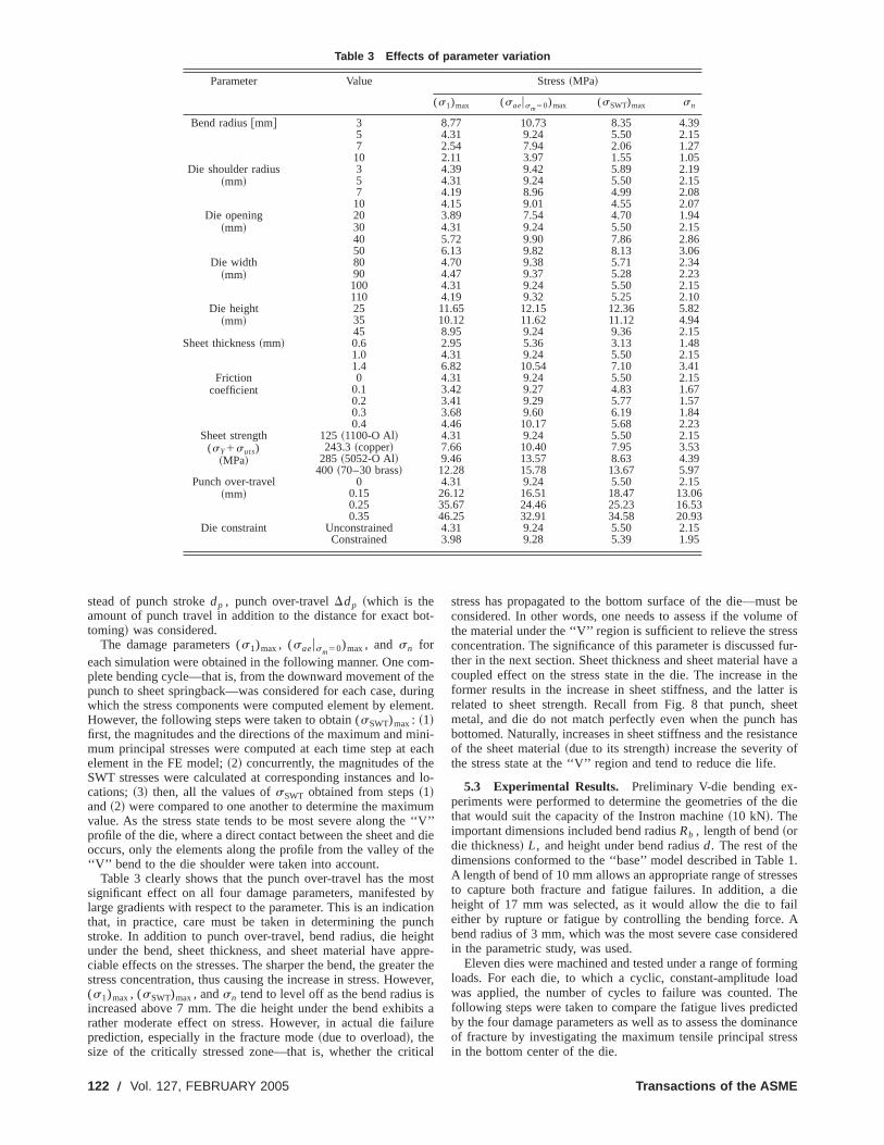
stead of punch strokedp , punch over-travelDdp ~which is theamount of punch travel in addition to the distance for exact btoming! was considered.
The damage parameters (s1)max, (saeusm50)max, and sn foreach simulation were obtained in the following manner. One coplete bending cycle—that is, from the downward movement ofpunch to sheet springback—was considered for each case, dwhich the stress components were computed element by elemHowever, the following steps were taken to obtain (sSWT)max: ~1!first, the magnitudes and the directions of the maximum and mmum principal stresses were computed at each time step atelement in the FE model;~2! concurrently, the magnitudes of thSWT stresses were calculated at corresponding instances ancations;~3! then, all the values ofsSWT obtained from steps~1!and~2! were compared to one another to determine the maximvalue. As the stress state tends to be most severe along theprofile of the die, where a direct contact between the sheet andoccurs, only the elements along the profile from the valley of‘‘V’’ bend to the die shoulder were taken into account.
Table 3 clearly shows that the punch over-travel has the msignificant effect on all four damage parameters, manifestedlarge gradients with respect to the parameter. This is an indicathat, in practice, care must be taken in determining the pustroke. In addition to punch over-travel, bend radius, die heiunder the bend, sheet thickness, and sheet material have aciable effects on the stresses. The sharper the bend, the greatstress concentration, thus causing the increase in stress. How(s1)max, (sSWT)max, andsn tend to level off as the bend radiusincreased above 7 mm. The die height under the bend exhibrather moderate effect on stress. However, in actual die faiprediction, especially in the fracture mode~due to overload!, thesize of the critically stressed zone—that is, whether the crit
, FEBRUARY 2005
ot-
m-heringent.
ini-each
d lo-
um‘‘V’’die
he
ostby
tionchht
ppre-r the
ever,sts aure
cal
stress has propagated to the bottom surface of the die—musconsidered. In other words, one needs to assess if the volumthe material under the ‘‘V’’ region is sufficient to relieve the streconcentration. The significance of this parameter is discussedther in the next section. Sheet thickness and sheet material hacoupled effect on the stress state in the die. The increase informer results in the increase in sheet stiffness, and the latterelated to sheet strength. Recall from Fig. 8 that punch, shmetal, and die do not match perfectly even when the punchbottomed. Naturally, increases in sheet stiffness and the resistof the sheet material~due to its strength! increase the severity othe stress state at the ‘‘V’’ region and tend to reduce die life.
5.3 Experimental Results. Preliminary V-die bending ex-periments were performed to determine the geometries of thethat would suit the capacity of the Instron machine~10 kN!. Theimportant dimensions included bend radiusRb , length of bend~ordie thickness! L, and height under bend radiusd. The rest of thedimensions conformed to the ‘‘base’’ model described in TableA length of bend of 10 mm allows an appropriate range of stresto capture both fracture and fatigue failures. In addition, aheight of 17 mm was selected, as it would allow the die to feither by rupture or fatigue by controlling the bending force.bend radius of 3 mm, which was the most severe case considin the parametric study, was used.
Eleven dies were machined and tested under a range of formloads. For each die, to which a cyclic, constant-amplitude lowas applied, the number of cycles to failure was counted. Tfollowing steps were taken to compare the fatigue lives predicby the four damage parameters as well as to assess the dominof fracture by investigating the maximum tensile principal strein the bottom center of the die.
Transactions of the ASME
ec
h
om
u
g.
p
ions
ests
tte.allyvet ap-ulatedd torse-essre-thes the
areeredpre-tress
e ofrs
am--
1. Punch displacement-controlled experiments were performat a prescribed punch force. That is, the displacement was dmined such that it would allow the desired maximum punch forThe load ranged between 5.1 and 8.8 kN. 2.
2. The FEA was performed, such that the punch was displafurther than would cause a punch force of 8.8 kN. The punchto be over-traveled to cause the force range described in Step~1!.The stress tensors were extracted for the time steps that csponded to the force range and were used to compute the daparameters along the ‘‘V’’ surface and in the bottom center.~Onlythe maximum tensile principal stresss1 was calculated for thebottom center.! Each damage parameter was expressed as a ftion of the maximum bending force in the range of interest~6.59,7.30, 8.35, 8.73, and 9.32 kN! to yield an equation correspondinto the curve~either linear or power law! fitted to the data pointsThe maximum tensile principal stresses in the die bottom awere fitted, and the equation of the fitted line iss153.51Fmax20.34 @MPa#, whereFmax is the punch force at a given time ste
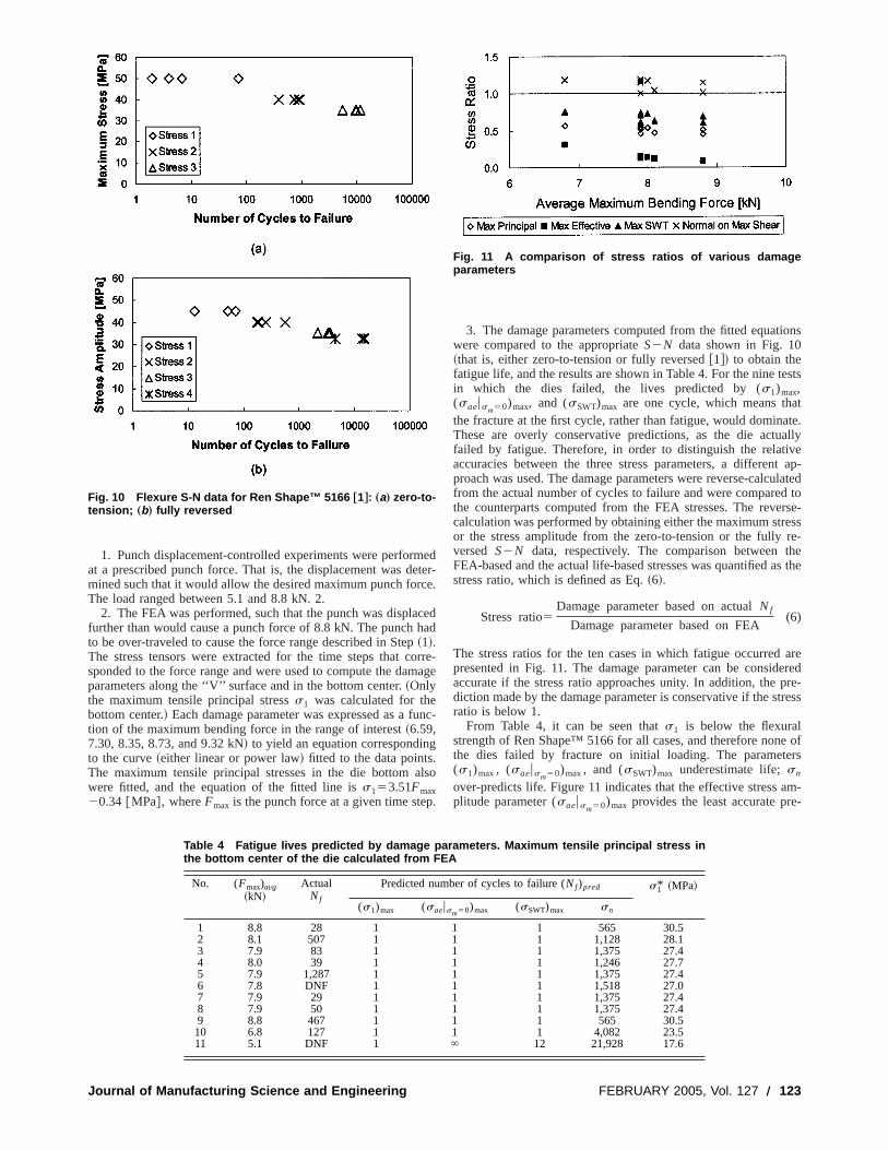
Fig. 10 Flexure S-N data for Ren Shape™ 5166 †1‡: „a… zero-to-tension; „b… fully reversed
Journal of Manufacturing Science and Engineering
edter-e.
cedad
rre-age
nc-
lso
.
3. The damage parameters computed from the fitted equatwere compared to the appropriateS2N data shown in Fig. 10~that is, either zero-to-tension or fully reversed@1#! to obtain thefatigue life, and the results are shown in Table 4. For the nine tin which the dies failed, the lives predicted by (s1)max,(saeusm50)max, and (sSWT)max are one cycle, which means thathe fracture at the first cycle, rather than fatigue, would dominaThese are overly conservative predictions, as the die actufailed by fatigue. Therefore, in order to distinguish the relatiaccuracies between the three stress parameters, a differenproach was used. The damage parameters were reverse-calcfrom the actual number of cycles to failure and were comparethe counterparts computed from the FEA stresses. The revecalculation was performed by obtaining either the maximum stror the stress amplitude from the zero-to-tension or the fullyversed S2N data, respectively. The comparison betweenFEA-based and the actual life-based stresses was quantified astress ratio, which is defined as Eq.~6!.
Stress ratio5Damage parameter based on actualNf
Damage parameter based on FEA(6)
The stress ratios for the ten cases in which fatigue occurredpresented in Fig. 11. The damage parameter can be considaccurate if the stress ratio approaches unity. In addition, thediction made by the damage parameter is conservative if the sratio is below 1.
From Table 4, it can be seen thats1 is below the flexuralstrength of Ren Shape™ 5166 for all cases, and therefore nonthe dies failed by fracture on initial loading. The paramete(s1)max, (saeusm50)max, and (sSWT)max underestimate life;sn
over-predicts life. Figure 11 indicates that the effective stressplitude parameter (saeusm50)max provides the least accurate pre
Fig. 11 A comparison of stress ratios of various damageparameters
Table 4 Fatigue lives predicted by damage parameters. Maximum tensile principal stress inthe bottom center of the die calculated from FEA
No. (Fmax)avg~kN!
ActualNf
Predicted number of cycles to failure (Nf)pred s1* ~MPa!
(s1)max (saeusm50)max (sSWT)max sn
1 8.8 28 1 1 1 565 30.52 8.1 507 1 1 1 1,128 28.13 7.9 83 1 1 1 1,375 27.44 8.0 39 1 1 1 1,246 27.75 7.9 1,287 1 1 1 1,375 27.46 7.8 DNF 1 1 1 1,518 27.07 7.9 29 1 1 1 1,375 27.48 7.9 50 1 1 1 1,375 27.49 8.8 467 1 1 1 565 30.510 6.8 127 1 1 1 4,082 23.511 5.1 DNF 1 ` 12 21,928 17.6
FEBRUARY 2005, Vol. 127 Õ 123

fei
s
sptd
rd
d
g
us
i
ii
renrs
R
rvo-/mins.sig-ityeed
hehethe
d-that
thede ofreap-
ns.traintheilure
oading.s on
tressingideshatby
terialuide-,
edd. Ain-ith
elartin
e to
h-uldh,offor
,’’
ing
of
2,J.
.,t.
al
diction. The parameters (sSWT)max andsn offer similar degrees ofaccuracy, as the ideal stress ratio line lies between the two.
Figure 12~a! presents the typical fatigue failure mode that ocurred in a V-bending die. The crack nucleated near the end obend arc~as indicated in the figure! and propagated through thheight of the die leading to fracture. The location of crack inittion is in agreement with the stress states predicted by the FThe photo of a die that underwent catastrophic fracture~or‘‘crushing’’ ! due to punch overload is shown in Fig. 12~b!. Thecrack initiated in the bottom center of the die and propagaupward. The crack was caused by the maximum tensile princstress~which acts in the horizontal direction!, as can be seen by itorientation.
5.4 General Die Design Guidelines. The parametric studyand the experimental results presented in the previous sectionbe used to develop general tool design guidelines for Ren Sha5166. For V-die bending, it is desirable to design the die suchfracture or fatigue does not occur before producing the intennumber of parts.
As for determining the geometries of a V-bending die, the ‘‘Vnotch can be considered as the stress raiser. Naturally, as theradius ~or notch radius! decreases, the critical stresses increaBased on the FEA performed in the parametric study, the stlevels show an exponential decrease with increasing bend raFollowing an exponential decay, the stresses tend to level ofthe bend radius increases beyond 7 mm. This rule applies todies that have sufficient thickness~or length of bend!, as the FEAwas performed under plane strain condition. It is recommenthat a die opening of less than 30 mm be used, which wowarrant stabilized minimal stress levels. In addition, die heiunder the bend radius must be chosen carefully such that theume of material is large enough to absorb the strain energy dudeformation, especially when a small bend radius is used anlarge punch over-travel is applied.
Further modification can be applied to die geometry to redthe stress concentration in the ‘‘V’’ region. As observed previouin Fig. 8, the nonconformity between the sheet metal and theleads to the tensile stress at the gap, which subjects the dfatigue crack nucleation. The die can be designed such that mmaterial is present to ‘‘fill’’ or compensate for the gap, thus dtributing the compressive stress more uniformly and minimizthe tensile stress. It is recommended that the modification be mbased on the FEA, as the amount of gap depends on severarameters, namely, sheet material and thickness, and bend raHowever, the amount and the geometry of the additional matemust be determined carefully, as it may distort the final geomeof the part being bent, as well as the stress in the die.
Important process parameters to consider include punch stand speed. Because the stresses at the ‘‘V’’ notch and thereforassociated die life are extremely sensitive to punch travel distaIn the FEA, the stress increased by as much as 10 MPa pemm of punch over-travel. Therefore, modified bending processuch as coining, which involves high, localized compressstresses between punch nose and die surface to compensaspringback, are not recommended. The manufacturer of
Fig. 12 Failure modes in a V-bending die: „a… fatigue failure;„b… fracture due to overload
124 Õ Vol. 127, FEBRUARY 2005
c-the
a-EA.
tedipal
cane™hated
’’bendse.essius.
f asthe
eduldhtvol-ringd a
celydiee toore
s-ngadel pa-dius.rialtry
okethece.0.1es,
ivete for
en
Shape™ 5166 specifies that the punch be driven by a sehydraulic system and that the speed does not exceed 760 mm~30 in/min! for most types of sheet metal forming operationHowever, for V-die bending, the punch speed should be keptnificantly lower than the specified value due to the high sensitivto punch over-travel. For example, doubling the crosshead spof the Instron~with no other load exerted except the weight of tload cell itself! resulted in doubling the force measured by tload cell due to the inertia of the crosshead unit. Therefore,punch speed~or the frequency if repetitive stamping is consiered! must be selected well below the suggested speed, suchplaten and die inertia effects are minimized.
6 ConclusionIn this paper, a failure analysis-based method to estimate
fatigue life of a 90° V-bending die fabricated from ATH-fillepolyurethane was presented. Based on the low-ductility naturthe tooling material, dictated by the matrix-filler debonding failumechanism, it was found that the local stress-based fatigueproach was appropriate for die failure mode and life predictioThe damage analysis of V-bending dies involved the stress–sanalysis of the forming process using the FEA and applyingdamage parameters to the materials data to predict die famode and life.
The experimental results showed that fracture due to overland fatigue are the competing die failure modes in V-die bendAmong the damage parameters considered, the normal stresthe maximum shear plane and the Smith–Watson–Topper sprovide the most accurate fatigue life prediction, the latter bemore conservative; the maximum tensile principal stress provsuitable fracture prediction. A parametric study revealed tpunch over-travel is the most significant parameter, followedbend radius, sheet thickness and strength, and volume of maunder the bend radius. These results establish the generic glines for V-bending die design for low-ductility, powder-filledpolymer composite tooling materials.
In order to expand the range of application of the developmethod, parts with more complex geometries can be considererectangular drawn part would be a good place to start, as itvolves both bending and stretching. However, since it deals was a three-dimensional problem~as the critical region is likely tobe at the corners!, the corresponding three-dimensional FE modmust be developed. A further modification to the rectangular pwould be adding local, protruding features, which would resultadding more critically stressed regions. Then the task would bdetermine the location of failure as well as the mode itself.
AcknowledgmentThe authors gratefully acknowledge Vantico Inc. for their tec
nical support and supply of their products. The authors also wolike to thank Professors David McDowell, Christopher LyncMin Zhou, and Richard Neu in the George W. Woodruff SchoolMechanical Engineering at Georgia Institute of Technologytechnical support and helpful discussions.
References@1# Park, Y., 2003, ‘‘Sheet Metal Forming Using Rapid Prototyped Tooling
Ph.D. thesis, Georgia Institute of Technology.@2# Nakagawa, T., 2000, ‘‘Advances in Prototype and Low Volume Sheet Form
and Tooling,’’ J. Mater. Process. Technol.,98, pp. 244–250.@3# Soar, R., Arthur, A., and Dickens, P., 1996, ‘‘Processing and Application
Rapid Prototyped Laminate Production Tooling,’’Proceedings of the 2nd Na-tional Conference on Rapid Prototyping and Tooling Research, pp. 65–76.
@4# Du, Z. H., Chua, C. K., Chua, Y. S., Loh-Lee, K. G., and Lim, S. T., 200‘‘Rapid Sheet Metal Manufacturing. Part 1: Indirect Rapid Tooling,’’ Int.Adv. Manuf. Technol.,19, pp. 411–417.
@5# Cheah, C. M., Chua, C. K., Lee, C. W., Lim, S. T., Eu, K. H., and Lin, L. T2002, ‘‘Rapid Sheet Metal Manufacturing. Part II: Direct Rapid Tooling,’’ InJ. Adv. Manuf. Technol.,19, pp. 510–515.
@6# Walczyk, D. F., and Hardt, D. E., 1998, ‘‘Rapid Tooling for Sheet Met
Transactions of the ASME
o
a
R
sa
ld
-
ion
Forming Using Profiled Edge Laminations—Design Principles and Demstration,’’ ASME J. Manuf. Sci. Eng.,120, pp. 746–754.
@7# Altan, T., and Vazquez, V., 1996, ‘‘Numerical Process Simulation for Tool aProcess Design in Bulk Metal Forming,’’ CIRP Ann.,45, pp. 599–615.
@8# Knoerr, M., Lange, K., and Altan, T., 1994, ‘‘Fatigue Failure of Cold ForginTooling: Causes and Possible Solutions through Fatigue Analysis,’’ J. MProcess. Technol.,46, pp. 57–71.
@9# Hettig, A., Reiss, W., and Lange, K., 1989, ‘‘A Study of Tool Fracture in CoExtrusion,’’ Transactions of NAMRI/SME,XVII , Columbus, OH, pp. 49–53.
@10# Knoerr, M., Lange, K., and Altan, T., 1992, ‘‘An Integrated Approach to Prcess Simulation and Die Stress Analysis in Forging,’’ Transactions of NAMSME, XX , Pullman, WA, pp. 53–60.
@11# Geiger, M., Hansel, M., and Rebhan, T., 1992, ‘‘Improving the Fatigue Retance of Cold Forging Tools by FE Simulation and Computer Aided Die Sh
Journal of Manufacturing Science and Engineering
n-
nd
gter.
ld
o-I/
is-pe
Optimization,’’ IMechE, Part B: J. of Eng. Manuf.,206, pp. 143–150.@12# Kalpakjian, S., 1997,Manufacturing Processes for Engineering Materials, 3rd
ed., Addison-Wesley, Menlo Park, CA.@13# Suchy, I., 1998,Handbook of Die Design, McGraw-Hill, New York, NY.@14# American Society of Tool and Manufacturing Engineers, 1965,Die Design
Handbook, 2nd ed., McGraw-Hill, New York, NY.@15# Cser, L., and Geiger, M., 1991, ‘‘A Generalized Life Time Model for Co
Extrusion Tools,’’ CIRP Ann.,40~1!, pp. 299–301.@16# Bannantine, J. A., Comer, J. J., and Handrock, J. L., 1990,Fundamentals of
Metal Fatigue Analysis, Prentice–Hall, Englewood Cliffs, NJ.@17# Suresh, S., 1998,Fatigue of Materials, Cambridge University Press, Cam
bridge, UK.@18# Smith, K. N., Watson, P., and Topper, T. H., 1970, ‘‘A Stress–Strain Funct
for the Fatigue of Metals,’’ J. Mater.,5~4!, pp. 767–778.
FEBRUARY 2005, Vol. 127 Õ 125


![Fact sheet Heart failure sheets/fact sheet - heart failure.pdf · NICE guidance Chronic heart failure in adults: diagnosis and management [NG106], Section 1.1 Team working in the](https://static.fdocuments.in/doc/165x107/5ecdc0dfe662ff557e19b2c3/fact-sheet-heart-failure-sheetsfact-sheet-heart-nice-guidance-chronic-heart.jpg)


