
Sheet Descriptions TeleGlide Riser (24 Series ... · Riser/Adapter Upper Clamp Lower Clamp Figure 4...
4
Striem 3100 Brinkerhoff Kansas City, KS 66115 Tel: 913-222-1500 Fax: 913-291-0457 www.striemco.com Made in the U.S.A Adapter Adapter Cover Cover Gasket Gasket OS-100/OCT-275/ PS-275/CB-275/LB-275/BB-275 (standard) Upper clamp Lower clamp Lower clamp Upper clamp Cut location "C" LR24 (long riser) (optional component) Gasket Upper Clamp Lower Clamp Cut location "B" SR24 (short riser) (optional component) Gasket Lower Clamp Upper Clamp OS-35/OCT-35/PS-35/LB-35, OS-50/ OCT-50/PS-50/CB-50/LB-50/BB-50, OS-75/OCT-125/PS-125/CB-125/LB-125/BB-125 (standard) Adapter Cover Gasket Upper clamp Lower clamp Finished floor Figure 1 Riser Height Adapter Unit Call Striem with questions or suggestions @ 1-913-222-1500 Customer Service Hours: 8 AM-5 PM CST Figure 2 Adapter Riser Riser Height + Distance from step 5 4" Cut Mark Figure 3 Adapter Riser exceed 4"* Must be at least 2-1/2" and cannot Gasket Unit Riser/Adapter Upper Clamp Lower Clamp Figure 4 *3" for a GB-35 with 4" connections 5. Adjust adapter upwards to reach 20" to 22" 6. Adjust adapter upwards to reach 35" to 37" Cut location "A" Adapter Cover Adapter & Cover (standard component) Tools included (with base unit(s)) 7/16" Nut driver tool/bit • Silver permanent marker • Tools Needed: Tape measure • Regular or cordless drill with 1/2" chuck • Tools needed if Riser(s) require cutting: Jigsaw or • Cordless circular saw or • Reciprocating saw • Riser Assembly Instructions/Steps: If unit is to be installed on grade (on-the-floor), there is no need for any adjustments. 1. Unit is ready to be put into service. If unit is to be buried: Once unit is set so that the pipe connections line up with 2. jobsite piping, measure total riser height needed from top of cover to finished grade. Make sure you include any future tile work, etc. that may be installed in your finished grade measurements. See figure 1. Select according riser(s) needed based off Table 1. 3. If riser(s) is needed, remove cover(s) from adapter and remove adapter from main 4. unit by loosening upper clamp with included nut driver bit (lower band is factory set do not adjust or remove). On the floor near the unit, insert adaptor into first riser until it stops. If needed, insert bottom of first riser into top of second riser until it stops. You may need to tighten upper clamps during this step to keep risers from shifting. Adapter and riser(s) should sit level with each other. Removal of cover during this process will ease assembly. From the top of the adapter, measure your needed total riser height downward to the 5. sidewall of the riser. Then, add 5” (for OS-35, OCT-35, PS-35, or OS-50, OCT-50, PS-50, LB-50, BB-50) or 6” ( for OS-75, OCT-125, PS-125, CB-125, LB-125, BB-125 or OS-100, OCT-275, PS-275, CB-275, LB-275, BB-275). For example, if you have an OS-250 and need a 15-1/2” extension, you would measure down from the top of the adapter 21-1/2” (15-1/2” + 6” = 21-1/2”). See Figure 2. Refer to Table 2, Table 3 or Table 3a to determine if, and where, any cuts need to be made. 6. If a cut needs to be made, make a circular line around the sidewall of the riser with the included silver marker at your riser height +dimension from step 5 . Using a jigsaw, circular saw or reciprocating saw, cut along your line. Discard/recycle the cutoff scrap. Whether the riser needs to be cut or not, make another mark with the silver marker on the 7. sidewall of the riser a distance of 4 INCHES (3 INCHES for a GB-35 w/ 4” connections) above the edge just cut. If you did not make a cut (meaning your riser height + dimension from step 5 line was beyond the bottom edge of your riser), still mark the sidewall of the riser 4 INCHES above where your riser height + dimension from step 5 line would have been. DO NOT cut this new line. Once the riser is installed into the main unit, this new line will end up at the top of the gasket and will aid in re-assembly. See Figure 3. IMPORTANT: Before the next step: 8. Make sure diffuser/s (if applicable) are installed inside the main unit at the appropriate 1. locations and check if there needs to be any flow control adjustment on the inlet diffuser. Refer to sheet 2 of the unit's installation instructions for flow control adjustment. Refer to sheet 1 of the unit's installation instructions for leak/water testing procedures. 9. Take riser(s) and adapters apart to reduce the weight during installation. Wipe all sidewalls and 10. inside of gasket with a damp cloth to remove jobsite dust/debris. Install components into the main unit starting from the lowest (cut) riser and working your way toward the finished floor level. Upper clamps at each gasket need to be loosened or removed to aid in assembly. Once riser(s)/adapter is inserted into gasket, upper clamp can be tightened. Verify that the bottom of the lowest riser is protruding at least 2-1/2” but no more than 4” into 11. the main unit from the top of the gasket. Your mark from step 7 should be at the top edge of the gasket on the main unit. If measurements were made correctly, this should happen automatically. See figure 4. If tilting of the adapter is required to be flush with finished grade, it must be done AFTER all 12. clamps have been tightened with riser(s)/adaptor in a vertical and level position. Tilting is achieved by using the flexibility of the gasket. If tilting is done before clamps are tightened, a perfect gasket seal may be compromised. Schier recommends tilting only the adapter versus the entire riser assembly to make sure your riser height is maintained. Tighten all clamps to a minimum of 5 and a maximum of 8 ft lbs. of torque. Use the same torque 13. as you would tighten a rubber no-hub coupling. The adapter must be adjusted upward to achieve certain extension heights. See Table 2, 14. Table 3 or Table 3a. If jobsite riser height conditions change after the above steps have been completed, there 15. may still be room for vertical adjustment in both directions. As long as minimum and maximum overlaps are maintained (see Figure 4), the adapter/riser(s) can be adjusted/cut as many times as necessary. Please follow these steps from the beginning to ensure the proper overlaps are maintained. 1. Adjust adapter upwards to reach 22" to 24" 2. Adjust adapter upwards to reach 37" to 39" 3. Adjust adapter upwards to reach 56" to 58" 4. Adjust adapter upwards to reach 70" to 72" 7. Adjust adapter upwards to reach 19" to 21" 8. Adjust adapter upwards to reach 34" to 36" TeleGlide Riser (24 Series) Installation Guidelines Sheet Descriptions Sheet #1 - OS Series, OCT Series, PS Series, CB Series, LB Series, BB Series (-50 thru - 275) Sheet #2 - BB Series (-500 & -1200) Sheer #3 - NT Series Sheet #4 - SV Series * For model PS-125-B with 6" connectors, the adapter will need to be trimmed if the riser height needed is between 0"-2". TELEGLIDE RISER (24 SERIES) INSTALLATION GUIDE ECO: 10/27/17 RS REV: DATE: DWG BY: DESCRIPTION: PROPRIETARY AND CONFIDENTIAL THE INFORMATION CONTAINED IN THIS DRAWING IS THE SOLE PROPERTY OF STRIEM, LLC. ANY REPRODUCTION IN PART OR AS A WHOLE WITHOUT THE WRITTEN PERMISSION OF STRIEM, LLC. IS PROHIBITED. SHEET NUMBER: 1 of 4
Transcript of Sheet Descriptions TeleGlide Riser (24 Series ... · Riser/Adapter Upper Clamp Lower Clamp Figure 4...

Striem3100 Brinkerhoff
Kansas City, KS 66115Tel: 913-222-1500Fax: 913-291-0457
www.striemco.com
Made in the U.S.A
Adapter
Adapter
Cover
Cover
GasketGasket
OS-100/OCT-275/PS-275/CB-275/LB-275/BB-275
(standard)
Upper clampLower clamp
Lower clampUpper clamp
Cut location "C"
LR24 (long riser)
(optional component)
Gasket
Upper Clamp
Lower Clamp
Cut location "B"
SR24 (short riser)
(optional component)
Gasket
Lower Clamp
Upper Clamp
OS-35/OCT-35/PS-35/LB-35, OS-50/OCT-50/PS-50/CB-50/LB-50/BB-50,
OS-75/OCT-125/PS-125/CB-125/LB-125/BB-125(standard)
Adapter Cover
GasketUpper clampLower clamp
Finished floor
Figure 1
Riser Height
Adapter
Unit
Call Striem with questions or suggestions @ 1-913-222-1500 Customer Service Hours: 8 AM-5 PM CST
Figure 2Adapter Riser
Riser Height + Distance from step 5 4"
CutMark
Figure 3
Adapter
Riser
exceed 4"*
Must be at least2-1/2" and cannot
Gasket
Unit
Riser/Adapter
Upper Clamp
Lower Clamp
Figure 4*3" for a GB-35 with 4" connections
5. Adjust adapter upwards to reach 20" to 22" 6. Adjust adapter upwards to reach 35" to 37"
Cut location "A"Adapter
Cover
Adapter & Cover (standard component)Tools included (with base unit(s))
7/16" Nut driver tool/bit•Silver permanent marker•
Tools Needed:Tape measure•Regular or cordless drill with 1/2" chuck•
Tools needed if Riser(s) require cutting:Jigsaw or•Cordless circular saw or•Reciprocating saw•
Riser Assembly Instructions/Steps:If unit is to be installed on grade (on-the-floor), there is no need for any adjustments. 1.Unit is ready to be put into service.
If unit is to be buried: Once unit is set so that the pipe connections line up with 2.jobsite piping, measure total riser height needed from top of cover to finished grade. Make sure you include any future tile work, etc. that may be installed in your finished grade measurements. See figure 1.
Select according riser(s) needed based off Table 1.3.
If riser(s) is needed, remove cover(s) from adapter and remove adapter from main 4.unit by loosening upper clamp with included nut driver bit (lower band is factoryset do not adjust or remove). On the floor near the unit, insert adaptor into first riser until it stops. If needed, insert bottom of first riser into top of second riser until it stops. You may need to tighten upper clamps during this step to keep risers from shifting. Adapter and riser(s) should sit level with each other. Removal of cover during this process will ease assembly.
From the top of the adapter, measure your needed total riser height downward to the 5.sidewall of the riser. Then, add 5” (for OS-35, OCT-35, PS-35, or OS-50,OCT-50, PS-50, LB-50, BB-50) or 6” ( for OS-75, OCT-125, PS-125, CB-125,LB-125, BB-125 or OS-100, OCT-275, PS-275, CB-275, LB-275, BB-275). For example, if you have an OS-250 and need a 15-1/2” extension, you would measure down from the top of the adapter 21-1/2” (15-1/2” + 6” = 21-1/2”). See Figure 2.
Refer to Table 2, Table 3 or Table 3a to determine if, and where, any cuts need to be made. 6.If a cut needs to be made, make a circular line around the sidewall of the riser with the included silver marker at your riser height +dimension from step 5. Using a jigsaw, circular saw or reciprocating saw, cut along your line. Discard/recycle the cutoff scrap.
Whether the riser needs to be cut or not, make another mark with the silver marker on the 7.sidewall of the riser a distance of 4 INCHES (3 INCHES for a GB-35 w/ 4” connections) above the edge just cut. If you did not make a cut (meaning your riser height + dimension from step 5 line was beyond the bottom edge of your riser), still mark the sidewall of the riser 4 INCHES above where your riser height + dimension from step 5 line would have been. DO NOT cut this new line. Once the riser is installed into the main unit, this new line will end up at the top of the gasket and will aid in re-assembly. See Figure 3.
IMPORTANT: Before the next step:8.Make sure diffuser/s (if applicable) are installed inside the main unit at the appropriate1.
locations and check if there needs to be any flow control adjustment on the inlet diffuser.Refer to sheet 2 of the unit's installation instructions for flow control adjustment.Refer to sheet 1 of the unit's installation instructions for leak/water testing procedures.9.
Take riser(s) and adapters apart to reduce the weight during installation. Wipe all sidewalls and 10.inside of gasket with a damp cloth to remove jobsite dust/debris. Install components into the main unit starting from the lowest (cut) riser and working your way toward the finished floor level. Upper clamps at each gasket need to be loosened or removed to aid in assembly. Once riser(s)/adapter is inserted into gasket, upper clamp can be tightened.
Verify that the bottom of the lowest riser is protruding at least 2-1/2” but no more than 4” into 11.the main unit from the top of the gasket. Your mark from step 7 should be at the top edgeof the gasket on the main unit. If measurements were made correctly, this should happen automatically. See figure 4.
If tilting of the adapter is required to be flush with finished grade, it must be done AFTER all 12.clamps have been tightened with riser(s)/adaptor in a vertical and level position. Tilting is achieved by using the flexibility of the gasket. If tilting is done before clamps are tightened, a perfect gasket seal may be compromised. Schier recommends tilting only the adapter versus the entire riser assembly to make sure your riser height is maintained.
Tighten all clamps to a minimum of 5 and a maximum of 8 ft lbs. of torque. Use the same torque 13.as you would tighten a rubber no-hub coupling.
The adapter must be adjusted upward to achieve certain extension heights. See Table 2, 14.Table 3 or Table 3a.
If jobsite riser height conditions change after the above steps have been completed, there 15.may still be room for vertical adjustment in both directions. As long as minimum and maximum overlaps are maintained (see Figure 4), the adapter/riser(s) can be adjusted/cut as many times as necessary. Please follow these steps from the beginning to ensure the proper overlaps are maintained.
1. Adjust adapter upwards to reach 22" to 24" 2. Adjust adapter upwards to reach 37" to 39" 3. Adjust adapter upwards to reach 56" to 58"4. Adjust adapter upwards to reach 70" to 72"
7. Adjust adapter upwards to reach 19" to 21" 8. Adjust adapter upwards to reach 34" to 36"
TeleGlide Riser (24 Series) Installation GuidelinesSheet Descriptions
Sheet #1 - OS Series, OCT Series, PS Series, CB Series, LB Series, BB Series (-50 thru - 275)Sheet #2 - BB Series (-500 & -1200)Sheer #3 - NT SeriesSheet #4 - SV Series
* For model PS-125-B with 6" connectors, the adapter will need to be trimmedif the riser height needed is between 0"-2".
TELEGLIDE RISER (24 SERIES) INSTALLATION GUIDE
ECO:10/27/17RS REV:DATE:DWG BY:
DESCRIPTION:
PROPRIETARY AND CONFIDENTIALTHE INFORMATION CONTAINED IN THIS DRAWING IS THE SOLE PROPERTY OF STRIEM, LLC.
ANY REPRODUCTION IN PART OR AS A WHOLE WITHOUT THE WRITTEN PERMISSION OF STRIEM, LLC. IS PROHIBITED.
SHEET NUMBER: 1 of 4

Striem3100 Brinkerhoff
Kansas City, KS 66115Tel: 913-222-1500Fax: 913-291-0457
www.striemco.com
Made in the U.S.A
Call Striem with questions or suggestions @ 1-913-222-1500 Customer Service Hours: 8 AM-5 PM CST
Cut location "C"
LR24 (long riser)
(optional component)
Gasket
Upper Clamp
Lower Clamp
Cut location "B"
SR24 (short riser)
(optional component)
Gasket
Lower Clamp
Upper Clamp
Figure 2Adapter Riser
Riser Height + Distance from step 5 4"
CutMark
Figure 3
Adapter
Riser
exceed 4"
Must be at least2-1/2" and cannot
Gasket
Unit
Riser/Adapter
Upper Clamp
Lower Clamp
Figure 4
Cut location "A"Adapter
Cover
Adapter & Cover (standard component)
Riser Height
Figure 1
Finished floor
Unit
Cover
Adapter
Upper clampLower clamp
Gasket
BB-500, BB-1200
Tools included (with unit(s))7/16" Nut driver tool/bit•Silver permanent marker•
Tools Needed:Tape measure•Regular or cordless drill with 1/2" chuck•
Tools needed if Riser(s) require cutting:Jigsaw or•Cordless circular saw or•Reciprocating saw•
Riser Assembly Instructions/Steps:If unit is to be installed on grade (on-the-floor), there is no need for any adjustments. 1.Unit is ready to be put into service.
If unit is to be buried: Once unit is set so that the pipe connections line up with 2.jobsite piping, measure total riser height needed from top of cover to finished grade. Make sure you include any future tile work, etc. that may be installed in your finished grade measurements. See figure 1.
Select according riser(s) needed based off Table 1.3.
If riser(s) is needed, remove cover(s) from adapter and remove adapter from main 4.unit by loosening upper clamp with included nut driver bit (lower band is factoryset do not adjust or remove). On the floor near the unit, insert adaptor into first riser until it stops. If needed, insert bottom of first riser into top of second riser until it stops. You may need to tighten upper clamps during this step to keep risers from shifting. Adapter and riser(s) should sit level with each other. Removal of cover during this process will ease assembly.
From the top of the adapter, measure your needed total riser height downward to the 5.sidewall of the riser. Then, add 6”. For example, if you have a BB-500 and need a 15-1/2” extension, you would measure down from the top of the adapter 21-1/2” (15-1/2” + 6” = 21-1/2”). See Figure 2.
Refer to Table 2, to determine if, and where, any cuts need to be made. 6.If a cut needs to be made, make a circular line around the sidewall of the riser with the included silver marker at your riser height +dimension from step 5. Using a jigsaw, circular saw or reciprocating saw, cut along your line. Discard/recycle the cutoff scrap.
Whether the riser needs to be cut or not, make another mark with the silver marker on the 7.sidewall of the riser a distance of 4 INCHES above the edge just cut. If you did not make acut (meaning your riser height + dimension from step 5 line was beyond the bottom edge ofyour riser), still mark the sidewall of the riser 4 INCHES above where your riser height+ dimension from step 5 line would have been. DO NOT cut this new line. Once the riser is installed into the main unit, this new line will end up at the top of the gasket and will aid in re-assembly. See Figure 3.
IMPORTANT: Before the next step:8.Refer to sheet 1 of the installation instructions for leak/water testing procedures.1.
Take riser(s) and adapters apart to reduce the weight during installation. Wipe all sidewalls and 9.inside of gasket with a damp cloth to remove jobsite dust/debris. Install components into the main unit starting from the lowest (cut) riser and working your way toward the finished floor level. Upper clamps at each gasket need to be loosened or removed to aid in assembly. Once riser(s)/adapter is inserted into gasket, upper clamp can be tightened.
Verify that the bottom of the lowest riser is protruding at least 2-1/2” but no more than 4” into 10.the main unit from the top of the gasket. Your mark from step 7 should be at the top edgeof the gasket on the main unit. If measurements were made correctly, this should happen automatically. See figure 4.
If tilting of the adapter is required to be flush with finished grade, it must be done AFTER all 11.clamps have been tightened with riser(s)/adaptor in a vertical and level position. Tilting is achieved by using the flexibility of the gasket. If tilting is done before clamps are tightened, a perfect gasket seal may be compromised. Striem recommends tilting only the adapter versus the entire riser assembly to make sure your riser height is maintained.
Tighten all clamps to a minimum of 5 and a maximum of 8 ft lbs. of torque. Use the same torque 12.as you would tighten a rubber no-hub coupling.
The adapter must be adjusted upward to achieve certain extension heights. See Table 2.13.
If jobsite riser height conditions change after the above steps have been completed, there 14.may still be room for vertical adjustment in both directions. As long as minimum and maximum overlaps are maintained (see Figure 4), the adapter/riser(s) can be adjusted/cut as many times as necessary. Please follow these steps from the beginning to ensure the proper overlaps are maintained.
1. Adjust adapter upwards to reach 22" to 24" 2. Adjust adapter upwards to reach 37" to 39" 3. Adjust adapter upwards to reach 56" to 58"4. Adjust adapter upwards to reach 70" to 72"
TeleGlide Riser (24 Series) Installation Guidelines
TELEGLIDE RISER (24 SERIES) INSTALLATION GUIDE
ECO:10/27/17RS REV:DATE:DWG BY:
DESCRIPTION:
PROPRIETARY AND CONFIDENTIALTHE INFORMATION CONTAINED IN THIS DRAWING IS THE SOLE PROPERTY OF STRIEM, LLC.
ANY REPRODUCTION IN PART OR AS A WHOLE WITHOUT THE WRITTEN PERMISSION OF STRIEM, LLC. IS PROHIBITED.
NOTES:Striem Lab Basins are not to be installed in any other manner except as shown. Consult local codes for separate trapping requirements, cleanout locations and additional installation instructions.
SHEET NUMBER: 2 of 4
Striem3100 Brinkerhoff
Kansas City, KS 66115Tel: 913-222-1500Fax: 913-291-0457
www.striemco.com
Made in the U.S.A
Call Striem with questions or suggestions @ 1-913-222-1500 Customer Service Hours: 8 AM-5 PM CST
Cut location "C"
LR24 (long riser)
(optional component)
Gasket
Upper Clamp
Lower Clamp
Cut location "B"
SR24 (short riser)
(optional component)
Gasket
Lower Clamp
Upper Clamp
Figure 2Adapter Riser
Riser Height + Distance from step 5 4"
CutMark
Figure 3
Adapter
Riser
exceed 4"*
Must be at least2-1/2" and cannot
Gasket
Unit
Riser/Adapter
Upper Clamp
Lower Clamp
Figure 4
Cut location "A"Adapter
Cover
Adapter & Cover (standard component)
Cover
Adapter
Upper clampLower clamp
Gasket
NT-30H thru NT-2000
Riser Height
Figure 1
Finished floor
Unit
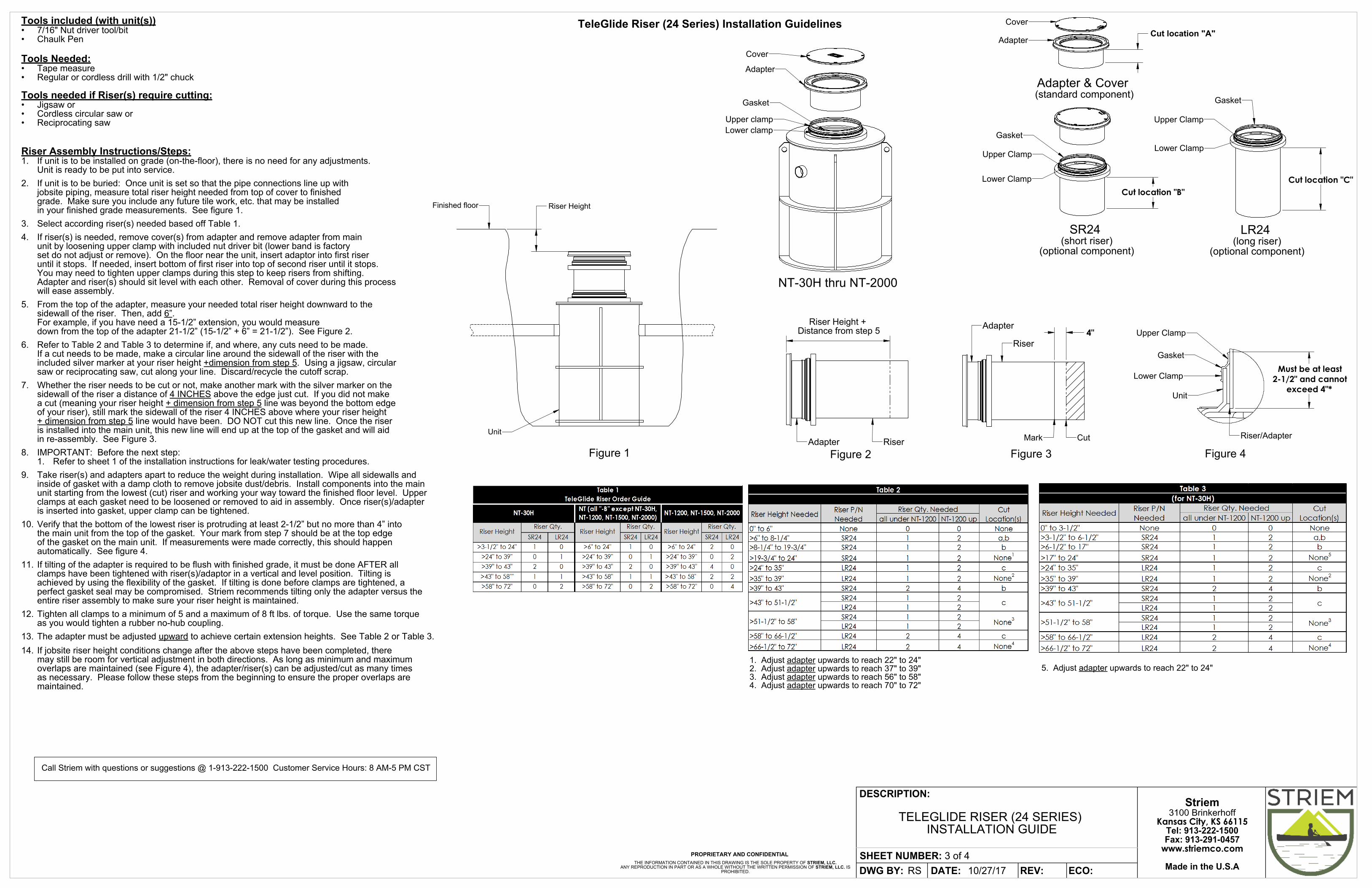
Tools included (with unit(s))7/16" Nut driver tool/bit•Chaulk Pen•
Tools Needed:Tape measure•Regular or cordless drill with 1/2" chuck•
Tools needed if Riser(s) require cutting:Jigsaw or•Cordless circular saw or•Reciprocating saw•
Riser Assembly Instructions/Steps:If unit is to be installed on grade (on-the-floor), there is no need for any adjustments. 1.Unit is ready to be put into service.
If unit is to be buried: Once unit is set so that the pipe connections line up with 2.jobsite piping, measure total riser height needed from top of cover to finished grade. Make sure you include any future tile work, etc. that may be installed in your finished grade measurements. See figure 1.
Select according riser(s) needed based off Table 1.3.
If riser(s) is needed, remove cover(s) from adapter and remove adapter from main 4.unit by loosening upper clamp with included nut driver bit (lower band is factoryset do not adjust or remove). On the floor near the unit, insert adaptor into first riser until it stops. If needed, insert bottom of first riser into top of second riser until it stops. You may need to tighten upper clamps during this step to keep risers from shifting. Adapter and riser(s) should sit level with each other. Removal of cover during this process will ease assembly.
From the top of the adapter, measure your needed total riser height downward to the 5.sidewall of the riser. Then, add 6”. For example, if you have need a 15-1/2” extension, you would measure down from the top of the adapter 21-1/2” (15-1/2” + 6” = 21-1/2”). See Figure 2.
Refer to Table 2 and Table 3 to determine if, and where, any cuts need to be made. 6.If a cut needs to be made, make a circular line around the sidewall of the riser with the included silver marker at your riser height +dimension from step 5. Using a jigsaw, circular saw or reciprocating saw, cut along your line. Discard/recycle the cutoff scrap.
Whether the riser needs to be cut or not, make another mark with the silver marker on the 7.sidewall of the riser a distance of 4 INCHES above the edge just cut. If you did not makea cut (meaning your riser height + dimension from step 5 line was beyond the bottom edgeof your riser), still mark the sidewall of the riser 4 INCHES above where your riser height+ dimension from step 5 line would have been. DO NOT cut this new line. Once the riseris installed into the main unit, this new line will end up at the top of the gasket and will aidin re-assembly. See Figure 3.
IMPORTANT: Before the next step:8.Refer to sheet 1 of the installation instructions for leak/water testing procedures.1.
Take riser(s) and adapters apart to reduce the weight during installation. Wipe all sidewalls and 9.inside of gasket with a damp cloth to remove jobsite dust/debris. Install components into the main unit starting from the lowest (cut) riser and working your way toward the finished floor level. Upper clamps at each gasket need to be loosened or removed to aid in assembly. Once riser(s)/adapter is inserted into gasket, upper clamp can be tightened.
Verify that the bottom of the lowest riser is protruding at least 2-1/2” but no more than 4” into 10.the main unit from the top of the gasket. Your mark from step 7 should be at the top edgeof the gasket on the main unit. If measurements were made correctly, this should happen automatically. See figure 4.
If tilting of the adapter is required to be flush with finished grade, it must be done AFTER all 11.clamps have been tightened with riser(s)/adaptor in a vertical and level position. Tilting is achieved by using the flexibility of the gasket. If tilting is done before clamps are tightened, a perfect gasket seal may be compromised. Striem recommends tilting only the adapter versus the entire riser assembly to make sure your riser height is maintained.
Tighten all clamps to a minimum of 5 and a maximum of 8 ft lbs. of torque. Use the same torque 12.as you would tighten a rubber no-hub coupling.
The adapter must be adjusted upward to achieve certain extension heights. See Table 2 or Table 3.13.
If jobsite riser height conditions change after the above steps have been completed, there 14.may still be room for vertical adjustment in both directions. As long as minimum and maximum overlaps are maintained (see Figure 4), the adapter/riser(s) can be adjusted/cut as many times as necessary. Please follow these steps from the beginning to ensure the proper overlaps are maintained.
TeleGlide Riser (24 Series) Installation Guidelines
1. Adjust adapter upwards to reach 22" to 24" 2. Adjust adapter upwards to reach 37" to 39" 3. Adjust adapter upwards to reach 56" to 58"4. Adjust adapter upwards to reach 70" to 72"
5. Adjust adapter upwards to reach 22" to 24"
TELEGLIDE RISER (24 SERIES) INSTALLATION GUIDE
ECO:10/27/17RS REV:DATE:DWG BY:
DESCRIPTION:
PROPRIETARY AND CONFIDENTIALTHE INFORMATION CONTAINED IN THIS DRAWING IS THE SOLE PROPERTY OF STRIEM, LLC.
ANY REPRODUCTION IN PART OR AS A WHOLE WITHOUT THE WRITTEN PERMISSION OF STRIEM, LLC. IS PROHIBITED.
NOTES:Striem Lab Basins are not to be installed in any other manner except as shown. Consult local codes for separate trapping requirements, cleanout locations and additional installation instructions.
SHEET NUMBER: 3 of 4
Striem3100 Brinkerhoff
Kansas City, KS 66115Tel: 913-222-1500Fax: 913-291-0457
www.striemco.com
Made in the U.S.A
Cut location "C"
LR24 (long riser)
(optional component)
Gasket
Upper Clamp
Lower Clamp
Cut location "B"
SR24 (short riser)
(optional component)
Gasket
Lower Clamp
Upper Clamp
Figure 2Adapter Riser
Riser Height + Distance from step 5 3"
CutMark
Figure 3
Adapter
Riser
exceed 4"*
Must be at least2-1/2" and cannot
Gasket
Unit
Riser/Adapter
Upper Clamp
Lower Clamp
Figure 4
Cut location "A"Adapter
Cover
Adapter & Cover (standard component)Adapter
Upper clamp
Lower clampGasket
Cover
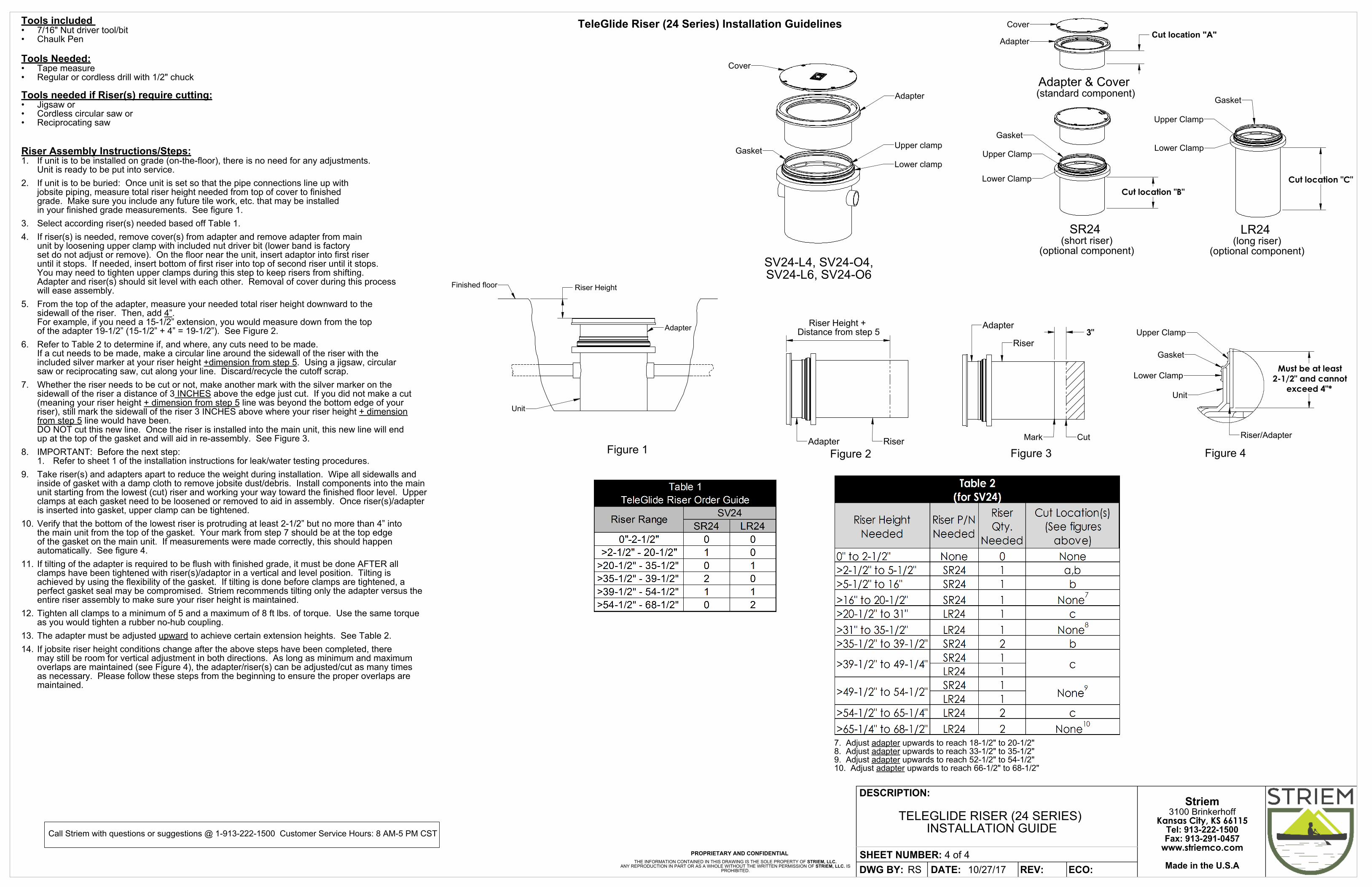
SV24-L4, SV24-O4, SV24-L6, SV24-O6
Riser Height
Figure 1
Finished floor
Adapter
Unit
7. Adjust adapter upwards to reach 18-1/2" to 20-1/2" 8. Adjust adapter upwards to reach 33-1/2" to 35-1/2" 9. Adjust adapter upwards to reach 52-1/2" to 54-1/2" 10. Adjust adapter upwards to reach 66-1/2" to 68-1/2"
Tools included 7/16" Nut driver tool/bit•Chaulk Pen•
Tools Needed:Tape measure•Regular or cordless drill with 1/2" chuck•
Tools needed if Riser(s) require cutting:Jigsaw or•Cordless circular saw or•Reciprocating saw•
Riser Assembly Instructions/Steps:If unit is to be installed on grade (on-the-floor), there is no need for any adjustments. 1.Unit is ready to be put into service.
If unit is to be buried: Once unit is set so that the pipe connections line up with 2.jobsite piping, measure total riser height needed from top of cover to finished grade. Make sure you include any future tile work, etc. that may be installed in your finished grade measurements. See figure 1.
Select according riser(s) needed based off Table 1.3.
If riser(s) is needed, remove cover(s) from adapter and remove adapter from main 4.unit by loosening upper clamp with included nut driver bit (lower band is factoryset do not adjust or remove). On the floor near the unit, insert adaptor into first riser until it stops. If needed, insert bottom of first riser into top of second riser until it stops. You may need to tighten upper clamps during this step to keep risers from shifting. Adapter and riser(s) should sit level with each other. Removal of cover during this process will ease assembly.
From the top of the adapter, measure your needed total riser height downward to the 5.sidewall of the riser. Then, add 4”. For example, if you need a 15-1/2” extension, you would measure down from the topof the adapter 19-1/2” (15-1/2” + 4” = 19-1/2”). See Figure 2.
Refer to Table 2 to determine if, and where, any cuts need to be made. 6.If a cut needs to be made, make a circular line around the sidewall of the riser with the included silver marker at your riser height +dimension from step 5. Using a jigsaw, circular saw or reciprocating saw, cut along your line. Discard/recycle the cutoff scrap.
Whether the riser needs to be cut or not, make another mark with the silver marker on the 7.sidewall of the riser a distance of 3 INCHES above the edge just cut. If you did not make a cut(meaning your riser height + dimension from step 5 line was beyond the bottom edge of yourriser), still mark the sidewall of the riser 3 INCHES above where your riser height + dimensionfrom step 5 line would have been. DO NOT cut this new line. Once the riser is installed into the main unit, this new line will end up at the top of the gasket and will aid in re-assembly. See Figure 3.
IMPORTANT: Before the next step:8.Refer to sheet 1 of the installation instructions for leak/water testing procedures.1.
Take riser(s) and adapters apart to reduce the weight during installation. Wipe all sidewalls and 9.inside of gasket with a damp cloth to remove jobsite dust/debris. Install components into the main unit starting from the lowest (cut) riser and working your way toward the finished floor level. Upper clamps at each gasket need to be loosened or removed to aid in assembly. Once riser(s)/adapter is inserted into gasket, upper clamp can be tightened.
Verify that the bottom of the lowest riser is protruding at least 2-1/2” but no more than 4” into 10.the main unit from the top of the gasket. Your mark from step 7 should be at the top edgeof the gasket on the main unit. If measurements were made correctly, this should happen automatically. See figure 4.
If tilting of the adapter is required to be flush with finished grade, it must be done AFTER all 11.clamps have been tightened with riser(s)/adaptor in a vertical and level position. Tilting is achieved by using the flexibility of the gasket. If tilting is done before clamps are tightened, a perfect gasket seal may be compromised. Striem recommends tilting only the adapter versus the entire riser assembly to make sure your riser height is maintained.
Tighten all clamps to a minimum of 5 and a maximum of 8 ft lbs. of torque. Use the same torque 12.as you would tighten a rubber no-hub coupling.
The adapter must be adjusted upward to achieve certain extension heights. See Table 2.13.
If jobsite riser height conditions change after the above steps have been completed, there 14.may still be room for vertical adjustment in both directions. As long as minimum and maximum overlaps are maintained (see Figure 4), the adapter/riser(s) can be adjusted/cut as many times as necessary. Please follow these steps from the beginning to ensure the proper overlaps are maintained.
TeleGlide Riser (24 Series) Installation Guidelines
Call Striem with questions or suggestions @ 1-913-222-1500 Customer Service Hours: 8 AM-5 PM CST
TELEGLIDE RISER (24 SERIES) INSTALLATION GUIDE
ECO:10/27/17RS REV:DATE:DWG BY:
DESCRIPTION:
PROPRIETARY AND CONFIDENTIALTHE INFORMATION CONTAINED IN THIS DRAWING IS THE SOLE PROPERTY OF STRIEM, LLC.
ANY REPRODUCTION IN PART OR AS A WHOLE WITHOUT THE WRITTEN PERMISSION OF STRIEM, LLC. IS PROHIBITED.
NOTES:Striem Lab Basins are not to be installed in any other manner except as shown. Consult local codes for separate trapping requirements, cleanout locations and additional installation instructions.
SHEET NUMBER: 4 of 4