SHEAR CONNECTION: DESIGN OF W-SHAPE BEAM TO W … · 3 = ⋅ Length of Beam, Lbm:=15ft 0in+ SHEAR...
21
SHEAR CONNECTION: DESIGN OF W-SHAPE BEAM TO W-SHAPE COLUMN WEB SHEAR PLATE CONNECTION (FULL-DEPTH EXTENDED SHEAR PLATE) CALCULATION FOR SHEAR CONNECTION 7.xmcd 1 of 21
Transcript of SHEAR CONNECTION: DESIGN OF W-SHAPE BEAM TO W … · 3 = ⋅ Length of Beam, Lbm:=15ft 0in+ SHEAR...

SHEAR CONNECTION: DESIGN OF W-SHAPE BEAM TO W-SHAPE
COLUMN WEB SHEAR PLATE CONNECTION (FULL-DEPTH EXTENDED
SHEAR PLATE)
CALCULATION FOR SHEAR CONNECTION 7.xmcd 1 of 21

Fycol 50 ksi⋅= dcol 14 in⋅= twcol 0.415 in⋅= k1col 1.063 in⋅=
Fucol 65 ksi⋅= bfcol 10 in⋅= tfcol 0.72 in⋅= kcol 1.563 in⋅=
Agcol 20 in2⋅= Sxcol 103 in
3⋅= E 29000ksi:=
W18X86 - A992BEAM PROPERTIES (bm):
Fybm 50 ksi⋅= dbm 18.4 in⋅= twbm 0.48 in⋅= k1bm 1.063 in⋅=
Fubm 65 ksi⋅= bfbm 11.1 in⋅= tfbm 0.77 in⋅= kbm 1.625 in⋅=
Agbm 25.3 in2⋅= Sxbm 166 in
3⋅= Length of Beam, Lbm 15ft 0in+:=
A572-50SHEAR PLATE (pl):
Fypl 50 ksi⋅= Fupl 65 ksi⋅= tpl 1in:=
A36 (AS REQUIRED)STIFFENER PLATE (st):
Fyst 36 ksi⋅= Fust 58 ksi⋅= tst3
8in:=
BOLTS:
I. DESIGN DATA AND LOAD ( LRFD - AISC 14th Edition )
For Shear Plate to Beam Connection:
Bolt Diameter, db 1 in⋅= Bolt_Type "A490-N"=
Bolt Shear Strength, Λrv 40.055 kips⋅= Conn_type "Bearing-type"=
Bolt Tensile Strength, Λrn 66.562 kips⋅=
W14X68 - A992COLUMN PROPERTIES (col):
Beam Edge Distance, Lehbm 1.5 in⋅= Hole diameter:
Plate Vertical Edge
Distance,
Shear Plate,Lev 1.5 in⋅=
hdplv 1.125 in⋅= hdplh 1.375 in⋅=
Plate Horizontal Edge
Distance,Leh 1.5 in⋅=
Beam,
hdbm 1.125 in⋅=Bolt Vertical Spacing, s 3 in⋅=
Bolt Horizontal Spacing
(For Multiple bolt
lines),
sv 3 in⋅=
CALCULATION FOR SHEAR CONNECTION 7.xmcd 2 of 21
Bolt First Down from
Top of beam,
D 3.25 in⋅=
Gap between edge of
beam to edge of support,gap
1
2in:=
number of bolt rows: nr 5:=
number of vertical bolt lines: nv 4:=
total number of bolts: n nr nv⋅:= n 20=
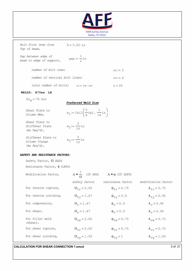
WELDS: E70xx LH
Fuw 70 ksi⋅= Preferred Weld Size
Shear Plate to
Column Web,w1 Ceil
5
8tpl
1
16in,
:=
Shear Plate to
Stiffener Plate
(As Req'd),
w2
3
16in:=
Stiffener Plate to
Column Flange
(As Req'd),
w3
3
16in:=
SAFETY AND RESISTANCE FACTORS:
Safety Factor, Ω (ASD)
Resistance Factor, φ (LRFD)
Modification Factor, Λ1
Ω= (IF ASD) Λ ϕ= (IF LRFD)
safety factor resistance factor modification factor
For tension rupture, Ωtr 2.00= ϕtr 0.75= Λtr 0.75=
For tension yielding, Ωty 1.67= ϕty 0.9= Λty 0.90=
For compression, Ωc 1.67= ϕc 0.9= Λc 0.90=
For shear, Ωv 1.67= ϕv 0.9= Λv 0.90=
For fillet weld
(shear),
Ωvw 2.00= ϕvw 0.75= Λvw 0.75=
For shear rupture, Ωvr 2.00= ϕvr 0.75= Λvr 0.75=
For shear yielding, Ωvy 1.50= ϕvy 1= Λvy 1.00=
CALCULATION FOR SHEAR CONNECTION 7.xmcd 3 of 21

For bearing, Ωbrg 2.00= ϕbrg 0.75= Λbrg 0.75=
For web compression
buckling,
Ωcb 1.67= ϕcb 0.9= Λcb 0.90=
For web crippling, Ωcr 2.00= ϕcr 0.75= Λcr 0.75=
For web yielding, Ωwy 1.50= ϕwy 1= Λwy 1.00=
For flexural local
buckling,ϕb 0.9= Λb 0.90=
For flexural rupture, Ωfr 2.00= ϕfr 0.75=
Ωb 1.67=
APPLIED LOAD:
% UDL, UDL 0.5:=
Given Load if any, Vgiv 0kips:=
Λfr 0.75=
50% UDLBeam Shear Load, V 186 kips⋅=
Opposite Beam Shear
Load (if any),
V2 0kips:=
II. CALCULATIONS:
A. BEAM CHECK
1. Bolt Bearing Capacity on Beam
(AISC 14th Ed. Specifications Chapter J, Section J3.10,
pages 16.1-127 to 16.1-128)
Bearing Area,
Abrgbm db twbm⋅:=
Abrgbm 0.48 in2⋅=
Bolt centerline distance from face of support,
ab 0.5 bfcol twcol−( ) gap+ Lehbm+ 0.5 nv 1−( ) sv⋅+:=
ab 11.292 in⋅=
CALCULATION FOR SHEAR CONNECTION 7.xmcd 4 of 21
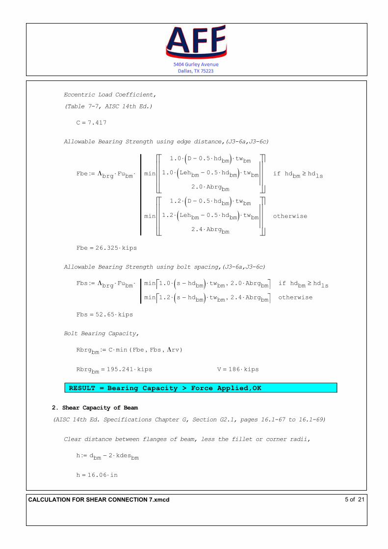
Eccentric Load Coefficient,
(Table 7-7, AISC 14th Ed.)
C 7.417=
Allowable Bearing Strength using edge distance,(J3-6a,J3-6c)
Fbe Λbrg Fubm⋅ min
1.0 D 0.5 hdbm⋅−( )⋅ twbm⋅
1.0 Lehbm 0.5 hdbm⋅−( )⋅ twbm⋅
2.0 Abrgbm⋅
hdbm hdls≥if
min
1.2 D 0.5 hdbm⋅−( )⋅ twbm⋅
1.2 Lehbm 0.5 hdbm⋅−( )⋅ twbm⋅
2.4 Abrgbm⋅
otherwise
⋅:=
Fbe 26.325 kips⋅=
Allowable Bearing Strength using bolt spacing,(J3-6a,J3-6c)
Fbs Λbrg Fubm⋅ min 1.0 s hdbm−( )⋅ twbm⋅ 2.0 Abrgbm⋅, hdbm hdls≥if
min 1.2 s hdbm−( )⋅ twbm⋅ 2.4 Abrgbm⋅, otherwise
⋅:=
Fbs 52.65 kips⋅=
Bolt Bearing Capacity,
Rbrgbm C min Fbe Fbs, Λrv, ( )⋅:=
Rbrgbm 195.241 kips⋅= V 186 kips⋅=
RESULT = Bearing Capacity > Force Applied,OK
2. Shear Capacity of Beam
(AISC 14th Ed. Specifications Chapter G, Section G2.1, pages 16.1-67 to 16.1-69)
Clear distance between flanges of beam, less the fillet or corner radii,
h dbm 2 kdesbm⋅−:=
h 16.06 in⋅=
CALCULATION FOR SHEAR CONNECTION 7.xmcd 5 of 21

Limiting depth-thickness ratio,
htw
h
twbm
:=
htw 33.458=
Clear distance between transverse stiffeners,
a 0in htw 260<if
min 3 h⋅260
htw
2
h⋅,
otherwise
:=
a 0 in⋅=
Web plate buckling coefficient,
kv 5 htw 260<if
55
a
h
2+ otherwise
:=
(G2-6)
kv 5=
Web shear coefficient,
Cv 1 htw 1.1kv E⋅
Fybm
⋅≤if
1.1kv E⋅
Fybm
⋅
htw
1.1kv E⋅
Fybm
⋅ htw< 1.37kv E⋅
Fybm
⋅≤if
1.51 E⋅ kv⋅
htw2Fybm
1.37kv E⋅
Fybm
⋅ htw<if
:=(G2-3)
(G2-4)
(G2-5)
Cv 1=
CALCULATION FOR SHEAR CONNECTION 7.xmcd 6 of 21

Shear Capacity of Section,
Rvbm Λvbm 0.6⋅ Fybm⋅ dbm⋅ twbm⋅ Cv⋅:= (G2-1)
Rvbm 264.96 kips⋅= V 186 kips⋅=
RESULT = Shear Capacity of Section > Force Applied, OK
B. BEAM TO SHEAR PLATE CHECK
1. Eccentric Bolt Shear Capacity
(AISC 14th Ed, Manual Part 7, pages 7-6 to 7-12)
Shear Capacity per bolt,
Λrv 40.055 kips⋅=
Eccentric Bolt Capacity,
Reb C Λrv⋅:=
Reb 297.072 kips⋅= V 186 kips⋅=
RESULT = Bolt Shear Capacity > Force Applied, OK
2. Check for Spacing
(AISC 14th Ed. Specifications Chapter J, Section J3.3 and J3.5, pages 16.1-122
to 16.1-124)
Vertical Spacing,
s 3 in⋅=
smin 22
3db⋅:=
smin 2.667 in⋅=
smax min 12in 24 min twbm tpl, ( )⋅, ( ):=
smax 11.520 in⋅=
RESULT = s > s.min & s < s.max, OK
CALCULATION FOR SHEAR CONNECTION 7.xmcd 7 of 21

Horizontal Spacing,
sv 3 in⋅=
svmin 22
3db⋅:=
svmin 2.667 in⋅=
svmax min 12in 24 min twbm tpl, ( )⋅, ( ):=
svmax 11.520 in⋅=
RESULT = sv > sv.min & sv < sv.max, OK
3. Check for Edge Distance
(AISC 14th Ed. Specifications Chapter J, Section J3.4 and J3.5, pages 16.1-122
to 16.1-124)
Vertical Edge Distance,
Lev 1.5 in⋅=
Lemin 1.25 in⋅=
C2 0 in⋅=
Levmin Lemin C2+:=
Levmin 1.25 in⋅=
Levmax min 6in 12 tpl⋅, ( ):=
Levmax 6.000 in⋅=
RESULT = Lev > Lev.min & Lev < Lev.max, OK
Horizontal Edge Distance,
Leh 1.5 in⋅=
Lehbm 1.5 in⋅=
Lemin 1.25 in⋅=
Lehminpl 1.375 in⋅=
Lehminbm 1.25 in⋅=
CALCULATION FOR SHEAR CONNECTION 7.xmcd 8 of 21
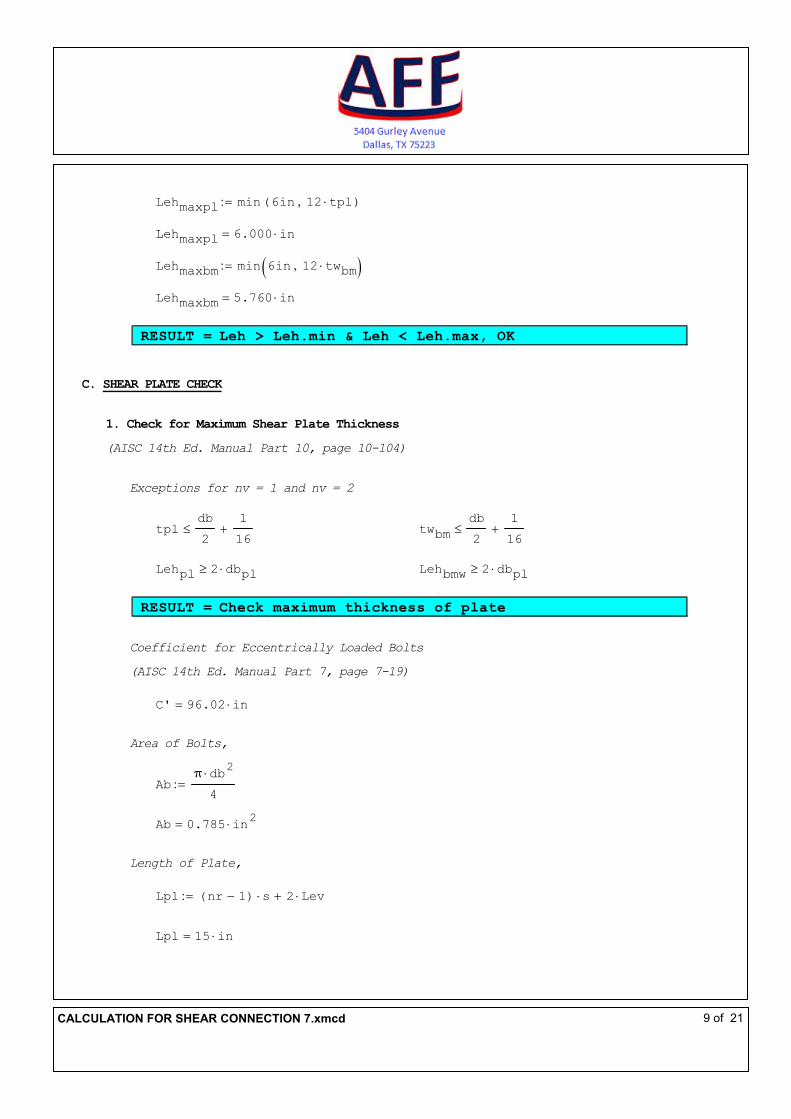
Lehmaxpl min 6in 12 tpl⋅, ( ):=
Lehmaxpl 6.000 in⋅=
Lehmaxbm min 6in 12 twbm⋅, ( ):=
Lehmaxbm 5.760 in⋅=
RESULT = Leh > Leh.min & Leh < Leh.max, OK
C. SHEAR PLATE CHECK
1. Check for Maximum Shear Plate Thickness
(AISC 14th Ed. Manual Part 10, page 10-104)
Exceptions for nv = 1 and nv = 2
tpldb
2
1
16+≤ twbm
db
2
1
16+≤
Lehpl 2 dbpl⋅≥ Lehbmw 2 dbpl⋅≥
RESULT = Check maximum thickness of plate
Coefficient for Eccentrically Loaded Bolts
(AISC 14th Ed. Manual Part 7, page 7-19)
C' 96.02 in⋅=
Area of Bolts,
Abπ db
2⋅
4:=
Ab 0.785 in2⋅=
Length of Plate,
Lpl nr 1−( ) s⋅ 2 Lev⋅+:=
Lpl 15 in⋅=
CALCULATION FOR SHEAR CONNECTION 7.xmcd 9 of 21

Maximum Thickness,
tplmax
6
Fnv1
0.9Ab⋅ C'⋅
⋅
Fypl Lpl2⋅
:=
tplmax 3.039 in⋅= tpl 1 in⋅=
RESULT = Plate Thickness < Max Thickness Permitted,OK
Governing Shear Plate Thickness
tplg
tpl tpl tplmax<if
tpl tpl tplmax=if
Floor tplmax
1
16in,
otherwise
Casepl 1=if
tpl otherwise
:=
tplg 1 in⋅=
2. Check for Stiffener Plate Requirement
(AISC 14th Ed. Manual Part 10, pages 10-105 to 10-106)
("On the Need for Stiffeners for the Effect of Lap Eccentricity on Extended
Single-Plate Connections", William A. Thornton and Patrick J. Fortney)
First bolt line distance from the face of support,
ab1 0.5 bfcol twcol−( ) gap+ Lehbm+:=
ab1 6.793 in⋅=
Available Strength to Resist Lateral Displacement,
Rreqst Λb1500 π⋅Lpl tplg
3⋅
ab12
⋅ ksi⋅:= (10-6)
Rreqst 1378.845 kips⋅= V 186 kips⋅=
RESULT = Lateral Displacement Capacity > Force Applied, OK
CALCULATION FOR SHEAR CONNECTION 7.xmcd 10 of 21

Check for Requirement of Stiffener Plates,
η
Rreqst
V:=
η 7.413=
RESULT = Stiffener Plates are NOT Required
Required Torsional Moment,
Mt V
twbm tpl+
2
⋅:= (10-8)
Mt 137.64 kips in⋅⋅=
Lateral Bending Capacity of Plate,
Rlbpl max Λvy 0.6⋅ Fypl⋅V
Lpl tplg⋅−
Lpl tplg2⋅
2⋅ 0kips in⋅,
:=
Rlbpl 132 kips in⋅⋅=
Lateral Bending Capacity of Beam,
Rlbbm
2 V2⋅ twbm tplg+( )⋅ bfbm⋅
Λb Fybm⋅ Lbm⋅ twbm2⋅
:=
Rlbbm 609.078 kips in⋅⋅=
Torsional Buckling Capacity,
Mreqst Rlbpl Rlbbm+ Beam_type "Composite"=if
Rlbpl otherwise
:= (10-7)
Mreqst 741.078 kips in⋅⋅= Mt 137.64 kips in⋅⋅=
RESULT = Torsional Buckling Capacity > Applied Force, OK
CALCULATION FOR SHEAR CONNECTION 7.xmcd 11 of 21

3. Bolt Bearing Capacity of Shear Plate
(AISC 14th Ed. Specifications Chapter J, Section J3.10,
pages 16.1-127 to 16.1-128)
Bearing Area,
Abrgpl db tplg⋅:=
Abrgpl 1 in2⋅=
Allowable Bearing Strength using edge distance, (J3-6a,J3-6c)
Fbe Λbrg Fupl⋅ min
1.0 Lev 0.5hdplv−( )⋅ tplg⋅
1.0 Leh 0.5hdplh−( )⋅ tplg⋅
2.0 Abrgpl⋅
hdplh hdls≥if
min
1.2 Lev 0.5hdplv−( )⋅ tplg⋅
1.2 Leh 0.5hdplh−( )⋅ tplg⋅
2.4 Abrgpl⋅
otherwise
⋅:=
Fbe 47.531 kips⋅=
Allowable Bearing Strength using bolt spacing, (J3-6a,J3-6c)
Fbs Λbrg Fupl⋅ min 1.0 s hdplv−( )⋅ tplg⋅ 2.0 Abrgpl⋅, hdplh hdls≥if
min 1.2 s hdplv−( )⋅ tplg⋅ 2.4 Abrgpl⋅, otherwise
⋅:=
Fbs 109.687 kips⋅=
Bolt Bearing Capacity,
Rbrgpl C min Fbe Fbs, Λrv, ( )⋅:=
Rbrgpl 297.072 kips⋅= V 186 kips⋅=
RESULT = Bearing Capacity > Force Applied, OK
CALCULATION FOR SHEAR CONNECTION 7.xmcd 12 of 21

4. Shear Yielding Capacity of Shear Plate
(AISC 14th Ed, Specifications Chapter J, Section J4.2, page 16.1-129)
Length of Plate,
Lpl nr 1−( )s 2Lev+:=
Lpl 15 in⋅=
Check if Length of Plate is acceptable,
(AISC 14th Ed, Manual Part 10, page 10-106)
Length "Plate Length is OK per AISC Requirements" Lpl 0.5 dbm 2kbm−( )≥if
"Increase Plate Length per AISC Requirements" otherwise
:=
Length "Plate Length is OK per AISC Requirements"=
Gross Shear Capacity,
Rvypl Λvy 0.6⋅ Fypl⋅ tplg⋅ Lpl⋅:= (J4-3)
Rvypl 450 kips⋅= V 186 kips⋅=
RESULT = Shear Yielding Capacity > Force Applied, OK
5. Shear Rupture Capacity of Shear Plate
(AISC 14th Ed, Specifications Chapter J, Section J4.2, page 16.1-129)
Net Area,
Anv Lpl nr hdplv⋅−( ) tplg⋅:=
Anv 9.375 in2⋅=
Shear Rupture Capacity,
Rvrpl Λvr 0.6⋅ Fupl⋅ Anv⋅:= (J4-4)
Rvrpl 274.219 kips⋅= V 186 kips⋅=
RESULT = Shear Rupture Capacity > Force Applied, OK
CALCULATION FOR SHEAR CONNECTION 7.xmcd 13 of 21

6. Block Shear Capacity of Shear Plate
(AISC 14th Ed. Specifications Chapter J, Section J4.3, page 16.1-129)
Reduction Factor, Ubs 1.0 nv 1=if
0.5 nv 1>if
:= (tension stress is uniform)
(tension stress is non-uniform)
Ubs 0.5=
Gross Shear Area
Agv nr 1−( ) s⋅ Lev+[ ] tplg⋅:=
Agv 13.5 in2⋅=
Net Tension Area
Ant Leh nv 1−( ) sv⋅+ nv 0.5−( ) hdplh⋅− tplg⋅:=
Ant 5.687 in2⋅=
Net Shear Area
Anv nr 1−( ) s⋅ Lev+ nr 0.5−( ) hdplv⋅− tplg⋅:=
Anv 8.438 in2⋅=
Block Shear Capacity of Plate, (J4-5)
Rbspl Λbs min 0.6Fupl Anv⋅ Ubs Fupl⋅ Ant⋅+ 0.6 Fypl⋅ Agv⋅ Ubs Fupl⋅ Ant⋅+, ( ):=
Rbspl 385.43 kips⋅= V 186 kips⋅=
RESULT = Block Shear Capacity > Force Applied, OK
7. Local Buckling Capacity of Shear Plate
(AISC 14th Ed., Manual Part 9, page 9-9)
Distance of bolt line to support,
ab gap Lehbm+( ) Stiffeners "Required"=if
ab1 otherwise
:=
ab 6.793 in⋅=
CALCULATION FOR SHEAR CONNECTION 7.xmcd 14 of 21

Coefficient,
λ
Lpl Fypl⋅
10 tplg⋅ 475 280Lpl
ab
2
+⋅
1
ksi
⋅:=
λ 0.247=
Q 1 λ 0.7≤if
1.34 0.486 λ⋅− 0.7 λ< 1.41≤if
1.30
λ2
otherwise
:=
Q 1=
Allowable Buckling Stress,
Fcr Fypl Q⋅:=
Fcr 50 ksi⋅=
Gross Plastic Section Modulus,
Zxpl
tplg Lpl2⋅
4
:=
Zxpl 56.25 in3⋅=
Eccentricity,
epl ab:=
epl 6.793 in⋅=
Buckling Capacity,
Rbcpl Λb
Fcr Zxpl⋅
epl
⋅:=
Rbcpl 372.654 kips⋅= V 186 kips⋅=
RESULT = Local Buckling Capacity will not Control!
CALCULATION FOR SHEAR CONNECTION 7.xmcd 15 of 21

8. Flexural Yielding Capacity with von-Mises shear reduction
(AISC 14th Ed., Manual Part 10, page 10-103/Muir, Larry and Hewitt,Christopher,
"Design of Unstiffened Extended Single-Plate Shear Connections", Engineering
Journal, 2nd Quarter 2009, page 69.)
Flexural Capacity,
Rfcpl
Λb Fypl⋅ Lpl⋅ tplg⋅
2.25 16
epl
Lpl
2
⋅+
:=
Rfcpl 287.015 kips⋅= V 186 kips⋅=
RESULT = Flexural Yielding Capacity > Applied Force, OK
9. Flexural Rupture Capacity
(AISC 14th Ed., Steel Construction Manual Design Examples page IIA-104)
Net Plastic Section Modulus,
Znetpl
tpl Lpl2⋅
4
hdplv s⋅ tpl⋅ nr2
1−( )⋅
4−
tpl hdplv( )2⋅
4−
mod nr 2, ( ) 0>if
tpl Lpl2⋅
4
hdplv nr2⋅ s⋅ tpl⋅
4− mod nr 2, ( ) 0=if
:=
Znetpl 35.684 in3⋅=
Flexural Rupture Capacity,
(AISC 14th Ed., Manual Part 15, page 15-4)
Rfrpl
Λfr Fupl⋅ Znetpl⋅
epl
:=
Rfrpl 256.102 kips⋅= V 186 kips⋅=
RESULT = Flexural Rupture Capacity > Applied Force, OK
CALCULATION FOR SHEAR CONNECTION 7.xmcd 16 of 21

9. Interaction of Shear Yielding, Shear Buckling, and Flexural Yielding of Plate
(AISC 14th Ed. Manual Part 10, page 10-104 to 10-105)
From AISC Manual Equation 10-5,
Vr
Vc
2Mr
Mc
2
+ 1.0≤
Vr V:=
Vr 186 kips⋅=
Mr Vr 0.5 bfcol twcol−( ) gap+ Lehbm+ 0.5 nv 1−( ) sv⋅+ ⋅:=
Mr 2100.405 kips in⋅⋅=
Shear yielding,
Vc Λvy 0.6⋅ Fypl⋅ tplg⋅ Lpl⋅:=
Vc 450 kips⋅=
Flexural yielding,
Mc Λb Fypl⋅ Zxpl⋅:=
Mc 2531.25 kips in⋅⋅=
Interaction,
Vr
Vc
2Mr
Mc
2
+ 0.859=
RESULT = Interaction < 1.0, OK
CALCULATION FOR SHEAR CONNECTION 7.xmcd 17 of 21

1. Weld Check for Shear Plate to Column Web
(AISC 14th Ed. Manual Part 8, pages 8-9 to 8-15)
No. of Weld side, nws 2:=
Minimum weld size,
wmin1
5
8in⋅= w1
5
8in⋅=
RESULT = Preferred Weld Size = Minimum Weld Size, OK
2. Weld Check for Shear Plate to Stiffener Plate
Minimum weld size,
wmin2
3
16in⋅= w2
3
16in⋅=
RESULT = This check is not applicable
3. Weld Check for Stiffener Plate to Column Flange
Minimum weld size,
wmin3
3
16in⋅= w3
3
16in⋅=
D. SHEAR PLATE TO COLUMN CHECK
RESULT = This check is not applicable
E. COLUMN CHECK
1. Rupture Strength at Weld for Column Web
(AISC 14th Ed. Manual Part 10, page 10-134)
Length of weld,
Lw nr 1−( ) s⋅ 2 Lev⋅+:=
Lw 15 in⋅=
CALCULATION FOR SHEAR CONNECTION 7.xmcd 18 of 21

Length of weld on opposite beam,
Lwo 12in:=
Effective Web Thickness,
tweff twcol
V
Lw
V
Lw
V2
Lwo
+
⋅:=
tweff 0.415 in⋅=
Rupture Strength at Weld,
Rvcol Λvr 0.6⋅ Fucol⋅ tweff⋅ nws⋅ Lw⋅:=
Rvcol 364.162 kips⋅= V 186 kips⋅=
RESULT = Column Web Capacity > Force Applied, OK.
CALCULATION FOR SHEAR CONNECTION 7.xmcd 19 of 21

III. DETAILS
A. SKETCH
SHEAR CONNECTION: DESIGN OF W-SHAPE BEAM TO W-SHAPE COLUMN
WEB SHEAR PLATE CONNECTION (FULL-DEPTH EXTENDED SHEAR PLATE)
CALCULATION FOR SHEAR CONNECTION 7.xmcd 20 of 21

B. TABLE: SHEAR CONNECTION SCHEDULE
IV. REFERENCES
Steel Construction Manual ( 14th )- LRFD American Institute of Steel
Construction, Inc. 2010
Size Gradetpl
(in)Grade
db
(in)Type nr nv
s
(in)
sv
(in)
Lev
(in)
Leh
(in)
W14X68 A992 3 1/4 1 A572-
501 A490-N 5 4 3 3 1 1/2 1 1/2
Column Bolt Spacing Edge DistanceShear Plate Bolts at Shear PlateD
(in)
Edge
Distance
Size Gradetst
(in)Grade
Lehbm
(in)
w1
(in)
w2
(in)
w3
(in)
W18X86 A992 NR NR 1 1/2 1/2 5/8 NR NR 186.00 195.24Bolt Bearing on
Beam Web
gap
(in)
Rcap
(kips)
Beam
Shear
Load
(kips)
BeamGoverning
Capacity
Weld SizeStiffener
Plate
CALCULATION FOR SHEAR CONNECTION 7.xmcd 21 of 21