SHEAR AND MOMENT TRANSFER BETWEEN CONCRETE SLABS AND …
21
PORTLAND CEMENT ASSOCIATION RESEARCH AND DEVELOPMENT LABORATORIES SHEAR AND MOMENT TRANSFER BETWEEN CONCRETE SLABS AND COLUMNS By Norman W. Hanson and John M. Hanson Reprinted from Journal of the PCA Research and Development Laboratories Vol. 10, No. 1, 2-16 (January 1968) @ por+land Cement Association, 1968
Transcript of SHEAR AND MOMENT TRANSFER BETWEEN CONCRETE SLABS AND …

PORTLAND CEMENT ASSOCIATIONRESEARCH AND DEVELOPMENT LABORATORIES
SHEAR AND MOMENT
TRANSFER BETWEEN
CONCRETE SLABS
AND COLUMNS
By Norman W. Hanson andJohn M. Hanson
Reprinted from Journal of the PCA
Research and Development Laboratories
Vol. 10, No. 1, 2-16 (January 1968)@ por+land Cement Association, 1968
SHEAR AND MOMENT TRANSFER BETWEENCONCRETE SLABS AND COLUMNS
By Norman W. Hanson and John M. Hanson
PORTLAND CEMEN’I ASSOCIATION
RESEARCH AND DEVELOPMENT LABORATORIES
.5420 Old orchard Road
Skokit!, Illinois 60076

N. W. Hanson J. M. Hanson
Shear and Moment Transfer
Between Concrete Slabs
and Columns
ByNorman W. Hanson
Senior Developmerd Engineer, andJohn M. Hanson
Senior Development EngineerStructural Development SectionResearch and Development LaboratoriesPortland Cement Association
SYNOPSIS
The strength of flat slabs near columns was investi-gated by 17 tests involving combined shear and un-balanced momenf loadings. Sixteen reinforced concreteslab-column specimens containing square or rectangu-lar interior columns and one specimen with a squareedge column were tested. Narrow rectangular hOleswere located adiacent to the columns in eight of thespecimens. Reversals of loading simulating earfhqua~eeffects were applied to three of the specimens. Fourdesign methods for shear strength, presented by DiStasio and Van Buren, Johannes Moe, ACI-ASCE Com-mittee 326, and the Commentary on the 1963 AC IBuilding Code, are evaluated in terms of Moe’s dataand test data reported herein. A modification of theCommittee 326 method is re.OmmendeJ fOr prac+icaldesign.
KEY WORDS: columns (structural ); concrete slabs:cyclic loads; flat plates (concrete ): flexural tests:openings: punching shear; shear tests; structural analy-sis
Design of flat plate concrete slabs is oftencon trolled by shear strength of the slab.Earthquake and wind loadings may causesubstantial unbalanced moments to betransferred between the slab and the col-umn. This makes shear even more criticalthan for gravity load alone.
The shear strength near columns ofsymmetrically loaded slabs has been exten-sively investigated. Previous work on thissubject was summarized by ACI-ASCECommittee 326 (now 426) on Shear andDiagonal Tension. c1) *
Only limited analytical and experimen-tal study has been devoted to slabcolumnjunctions subjected to both shear and un-balanced moment. This paper reports testsof specimens under such loading. Fourmethods for shear strength computation ofthese junctions are evaluated.
The 17 tests reported in this paper in-clude square and rectangular interior col-umns, square edge columns, and square in-terior columns with adjacent slab openings.Reversals of loading were applied to threeinterior column test specimens.
*Numbers in parentheses designate references atend of paper.
2 Journal of The PCA Research and
BACKGROUND
Previous Tesk
In 1959 Rosenthal z) reported the resultsof tests on simply supported circular rein-forced concrete slabs. These tests includedthree specimens loaded eccentricallythrough a centrally located circular stubcolumn.
The following year Tsuboi and Kawagu-chi fs) reported nine tests on square mortarslabs. Three of these slabs were made ofplain mortar. The distribution of the rein-forcement in the other six slabs varied, al-though all six contained an equal total~mount of reinforcement. These specimenswefe Joaded by applying a couple throughcentrally located square column stubs.
Kreps ~nd Reese(A) have reported the re-sults of six tests carried out by Frederickand ,Pollauf ( 5) on square flat plate speci-mens. These test were carried out to deter-
!mine the effecti e width of slab resistingmoment. Distribution. of reinforcement wasincluded as an important variable.
In 1961, Johannes Moe reported, in 13uL-
LETIN D47,( G)* 12 tests on 6-ft-square, 6-in. -thick slabs. The test specimens were simplysupported, and the corners were free to lift.Load was applied at different eccentricitiesthrough a centrally located square stub col-umn. The results of 10 of these tests arepresented in Table 1. Specimens M4 andM5 are not included here because theyfailed in flexure rather than shear. All thespecimens except M7 and M9 had a 2-in. -
●PCA DEVELOPMENT DES’ARTMENT BWLLETINSwillbe identified in the text primarily by tbe BuI.-LETINnumber. BI.JLLETSNSare available on re-quest in the United States and Canada.
diameter hole through the slab locatedalong the line of action of the applied load.
Methods for Pred;cfing Strength
Di Stasio and Van Buren.(7) A workingstress method of analysis was recommendedfor the strength of the slab-column junctionunder combinecl shear and unbalancedmoment loadings. The major criterion oftheir method is limitation” of the verticalshear stress on critical sections located at
spe:ified distances outside of the columnperiphery. The vertical shear stress is as-sumed to be distributed as shown in Fig. 1for typicaI interior and exterior flat plate-column connections. The vertical shearstress, v,, is calculated from
[ 1St V (M–m.~–mcD)c Cl..(l)
“== ~+ .Jc
where
c,= 1I+(n–l)p
and where, for an interior column
AC=2t(x+y)
~c _ X;t + Xt’ ‘~+yt
In Eq. (l), V and M are the resultant shearand unbalanced moment acting at the cen-troidal axis, c — c, of the critical section.The flexural moments on sides AB and CDof the critical section defined by x and yare mA~ and mcD. They are assumed equalto the moment that produces the maximumworking stress in either the concrete or ten-sion steel, including the effect of any com-pression steel. A= and J, are properties of
TABLE 1– SLAB TESTS BY MOE(6)
Effective Cylinder Reinforcement UltimateRatio, p
Ultimate
Specimen Depth, Column Strength, Moment
No.
ShearSize Transferred Tmn,f.srmsd
(i;.) (in.) i:;)Bottom TopFoce Face [i.. kips) (kips)
MIA 4.88 12X12 3020 0.0129 0 0 97.3
M2A 4.88 12X12 2250 0.0129 0 349 47.8
M4A 4.88 12X12 2560 0.0129 0 553 32.3
M2 4.88 12X12 3730 0.0129 0 506 65.7
M3 4.88 12X12 3295 0.0129 0 621 46.6
M6 4.81 10X1O 3s40 0.0117 0 356 53.8M7 4.81 10X1O 3620 0.0117 0 168 70.0
MB 4.B 1 10X1O 3570 0.0117 0.0054 57B 33.6
M9 4.81 10X1O 3370 0.0117 0 300 60.0
M1O 4.81 10X1O 3060 0.0117 0.0054 4B5 40.0
Development Laboratories, Januaq 19683
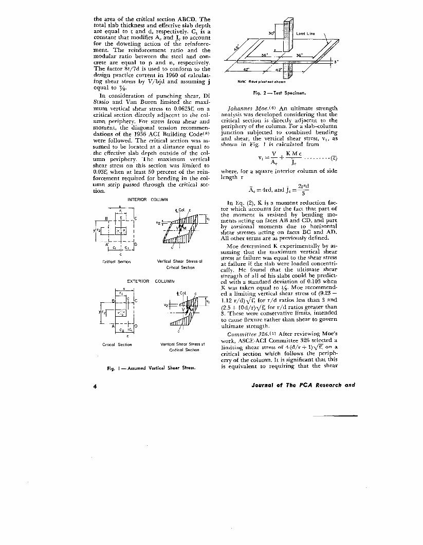
the area of the critical section ABCD. Thetotal slab thickness and effective slab depthare equal to t and d, respectively. Cl is aconstant that modifies A= and J. to accountfor the doweling action of the reinforce-ment. The reinforcement ratio and themodular ratio between the steel and con-crete are equal to p and n, respectively.The factor 8t/7d is used to conform to thedesign practice current in 1960 of calculat-ing shear stress by V/bjd and assuming jequal to 7/s.
In consideration of punching shear, DiStasio and Van Buren limited the maxi-mum vertical shear stress to 0.0625f~ on acritical section directly adjacent to the col-umn periphery. For stress from shear andmoment, the diagonal tension recommen-dations of the 1956 ACI Building Codef 81were followed. The critical section was as-sumed to be located at a distance equal tothe effective slab depth outside of the col-umn periphery. The maximum verticalshear stress on this section was limited to0.03f~ when at least 50 percent of the rein-forcement required for bending in the col-umn strip passed through the critical sec-tion,
INTERIOR COLUMN
x
~
rl
Bc -—
p+ ‘
r lC
Y r2 I .~~,’ I
L– ––i
‘W”c
Crit id Secilon
IV2
Vertical Shear Stress at
Criticol Section
ExTERIOR COLUMN
v I
c
Critical Section Vertical Shear Stress at
Critical Section
Fig. I — Assumed Vertical Shear Stress.
- .0
30” Lad Line
_z@/ ,7 J ,..&
s.
36” !,
3“
,! ,,
NOW Bose pivotmt shown
Fig. 2 - Test Specimen.
Johannes Moe.t G) An ultimate strengthanalysis was developed considering that thecritical section is directly adjacent to theperiphery of the column. For a slab-columnjunction subjected to combined bendingand shear, the vertical shear stress, VI, asshown in Fig. 1 is calculated from
v KMcVI ==--+ -.........(2)
A, J,
where, for a square interior column of sidelength r
Zr,d& = 4rd, and J,= ~
In Eq. (2), K is a moment reduction fac-tor which accounts for the fact that part ofthe moment is resisted by bending mo-ments acting on faces AB and CD, and partby torsional moments due to horizontalshear stresses acting on faces BC and AD.All other terms are as previously defined.
Moe determined K experimentally by as-suming that the maximum vertical shearstress at failure was equal to the shear stressat failure if the slab were loaded concentri-cally. He found that the ultimate shearstrength of all of his slabs could be predict-ed with a standard deviation of 0.103 whenK was taken equal to 1/3. Moe recommend-ed a limiting vertical shear stress of (9.23 —1.12 r/d) ~~. for r/d ratios less than 3 and
(2.5 + 10d/r) ~~ for r/d ratios greater than3. These were conservative limits, intendedto cause flexure rather than shear to governultimate strength.
Committee 326. ( 1) After reviewing Moe’swork, ASCE-ACI Committee 326 selected alimiting shear stress of 4 (d/r + 1) ~z on acritical section which follows the periph-ery of the column. It is significant that thisis equivalent to requiring that the shear
4 Journal of The PCA Research and

stress be limited to 4~~ on the critical sec-tion used in the 1963 ACI BuildingCodef 1o) and located at a distance d/2 out-side of the column periphery. Committee326 used the following expression to evalu-ate the results of 25 tests:
—..........(3)~l=y+KycAC J=
where, for an interior column
AC=2d(x+y)
All other terms are as previously defined.Based on this evaluation, Committee 326recommended limiting the shear stress to4 ~~ on a design critical section located adistance d/2 from the column and assum-ing K = 0.2.
Commentaryc~) on 1963 A CI BuildingCode. The Commentary also included aworking stress method for evaluating thestrength of the slabcolumn junction. Thismethod uses the equation
to calculate the maximum shear stress on acritical section defined in Fig. 1 by x and yequal to (rl + d) and (r, + 3t), respectively.All terms are as defined previously. Thiscalculated shear stress is limited to allow-able values specified in the 1963 ACIBuilding Code. ( 1o)
EXPERIMENTAL INVESTIGATION
Specimen Description
Seventeen specimens were tested. Eachwas intended to represent, in reduced scale,an isolated portion of slab surrounding acolumn as shown in Fig. 2. The columnhad hinged reaction points 30 in. aboveand below the surfaces of the 3-in. -thickslab. Loads were applied to the slab alonglines 36 in. from the centerline of the col-umn.
Four different column and slab configu-rations were tested. These were designatedas A, B, C, and D as shown in Fig. 3. Thecolumns in configurations A, B, and C werelocated in the center of a 48 x 84-in. slab.These included 12 specimens with 6-in. -square ~olumns located as in A, two sPeci-mens with a 6 x 12-in. column located as inB, and two specimens with a 12x 6-in. col-
6x6-in, Column 6x12-in. Column
12x6-in. Column 6x6-in. Column
Fig. 3 — Slab-and-Column Configurations.
umn located as in C. The remaining speci-men was made with a 6-in. -square columnlocated adjacent to and centered along thelong edge of a 48 x 45-in. slab, as shown inD.
The slabs were reinforced with two matsof No. 3 deformed bars spaced 3 in. center-to-center in each direction. The mats wereplaced so that the bars parallel to the longside of the slab were covered by 8/8 in. ofconcrete.
Pairs of 1 x 6-in. holes, as shown in Fig.4, were blocked out of the slab in eight of
81 11L
=—
‘@❑
p3—u6(’
“c“
dIl!ld-k-l-k
Fig. 4 — Holes Through Slabs.
Development Laboratories, January 7968

TABLE 2—MATERIAL PROPERTIES
Specimen r
No. S (j~i) (~i)
Al 4390 53.0A2 4540 54.5A3L 5370 52.8A4L 4850 54.2A5C 5080 53.9A6C S060 53.4B7 4780 51.4C8 4760 S9.6
A9 5040 53.5A1OL 4480 51.4A1l C 4850 50.5
Al 2 4820 54.0Al 3L 4760 53.7A14C 5160 54.0D15 4510 53.0B16 4410 49.4C17 5220 49.5
BThe first letter i“d LZCJtes the m ecimen confk ma tic.., os. .shown in Fig. 3. The last letter, when used, indicates thespecimens with holes, as shown i“ Fig. 4.
the specimens with square columns. Theseholes were located adjacent to the columnand either parallel to the long side or theshort side of the slab, indicated by L and C,respectively. The slab reinforcement wasrun through the holes.
The columns were reinforced with fourNo. 6 deformed bars. These bars wereplaced in the corners of the column with1/2 in. of concrete cover on each side. Tiesmade from No. 2 smooth bars, spaced at 4in. center-to-center, were used in the col-umn outside of the slab region.
MaterialsThe concrete was made with Type I
portland cement, Elgin sand and s/8-in.maximum size gravel. Measured slumpsranged from one to three inches. Concretestrengths at the time of test are listed inTable 2. Each of the strengths listed is theaverage from tests on six 6 x 12-in. cylin-ders. Three of these cylinders were takenfrom each of the two batches of concreteused for each specimen.
The reinforcement, with the exception ofthe smooth No. 2 bars used as column ties,met the requirements of ASTM A 15-66(11 Jintermediate grade steel with deformationsconforming to ASTM A305-65.( 1z) Theyield strength of the slab reinforcement ineach specimen is listed in Table 2.
Fabrication
The form for the test specimens wasmade of ~~-in. plywood suitably stiffened
6
with 2 x 4-in. lumber, and it was constrict-ed in such a manner that the entire speci-men could be cast at one time. The formwas oiled with a light form oil prior to cast-ing. The reinforcing mats were tied togeth-er with iron wire and were supported onwire chairs.
Two 6-cu-ft batches of concrete were re-quired to cast each specimen and its 6 x 12-in. test cylinders. The lower column andthe slab were placed severaI hours beforethe upper column was cast. An internal vi-brator was used to consolidate the concrete.The slab was screeded and the surface fin-ished with a wooden float.
About eighteen hours after the concretewas placed, the slab surface was coveredwith wet burlap and plastic sheets. Thismoist curing continued for seven days. Thespecimens were then removed from theform and stored for another seven days inthe laboratory at 73 F and 50 percent rela-tive humidity prior to testing. The test cyl-inders were cast in steel molds. They werevibrated internally and were cured in thesame way as the sIab-column specimens.
-L
I
I [r 3. +,[
4 “ ,S6°
30”
+I
Ilm
{,1
I
!$/Fig. 5 — Loading Methods.
Journal of The PCA Research and
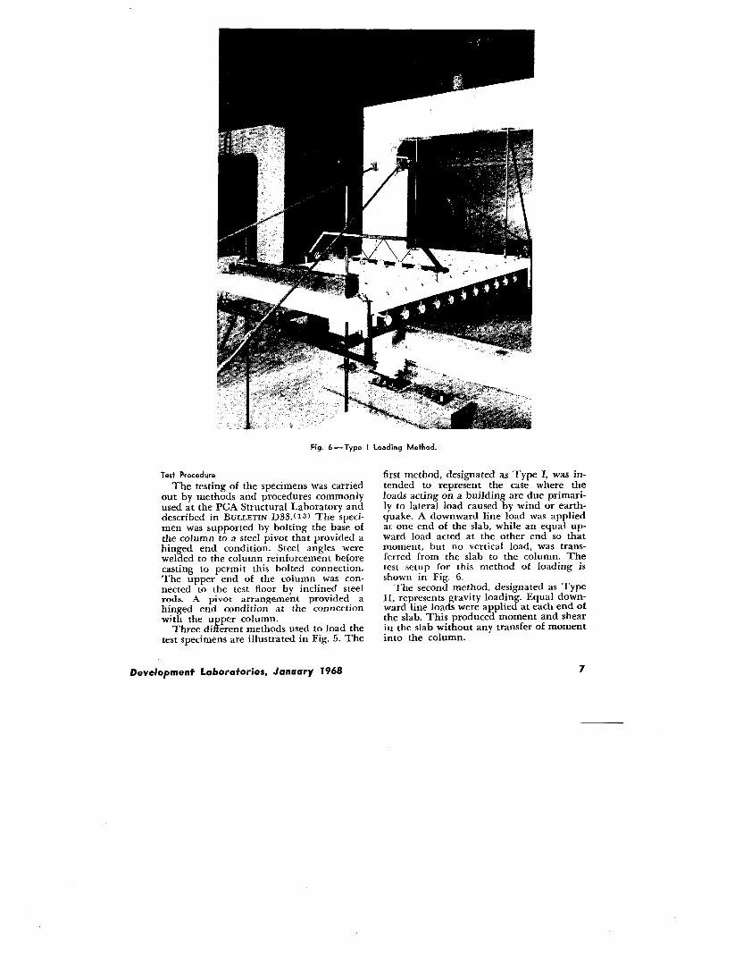
Fig. 6— Type I Loading Method.
Test Procedure
The testing of the specimens was carriedout by methods and procedures commonlyused at the PCA Structural Laboratory anddescribed in BULLETIN D33. (1s) The speci-men was supported by bolting the base ofthe column to a steel pivot that provided ahinged end condition. Steel angles werewelded to the column reinforcement beforecasting to permit this bolted connection.The upper end of the column was con-nected to the test floor by inclined steelrods. A pivot arrangement provided ahinged end condition at the connectionWith the upper column.
Three different methods used to load thetest specimens are illustrated in Fig. 5. The
Development Laboratories, January 1968
first method, designated as Type 1, was in-tended to represent the case where theloads acting on a building are due primari-ly to lateral load caused by wind or earth-quake. A downward line load was appliedat one end of the slab, while an equal up-ward load acted at the other end so thatmoment, but no vertical load, was trans-ferred from the slab to the column. Thetest setup for this method of loading isshown in Fig. 6.
The second method, designated as TypeII, represents gravity loading. Equal down-ward line loads were applied at each end ofthe slab. This produced moment and shearin the slab without any transfer of momentinto the column.
7
The third method, Type 111, representsloading caused by a combination of lateraland gravity loads. A downward line loadwas applied at only one end of the slab.This produced combined moment andshear at the slab-column junction.
Three of the specimens subjected to theType I loading were also subjected to rever-sal of loading. In these tests, the directionof the applied loads was reversed afterreaching 25, 50 and 75 percent of the ex-pected failure load.
Downward line loads on the slab wereapplied through a 4 x 4-in. steel tube cross-head 39 in. long as shown in Fig. 6. Eachsteel tube was seated in plaster on the slabsurface, Two steel rods 36 in. apart con-nected the steel tube to a similar crossheadbeneath the test floor. A 10-ton hydraulicram at the center of the lower crossheadreacted against the underside of the testfloor in the manner described in BULLETIND33. ( 13) The hydraulic ram was connectedby a flexible hydraulic hose to a pump andmeasurmg unit.
To produce upward line loads, the steeltube was placed against the underside ofthe slab. The hydraulic ram reacted againstan overhead concrete frame attached to thetest floor, as shown in Fig. 6. The loadswere measured by means of load cellsplaced between the hydraulic rams andtheir reaction.
Test loads were applied in increments of
approximately 5 percent Of the expectedfailure load. To apply a load increment,
{ ‘-——----I-I
___ ‘— ------ I
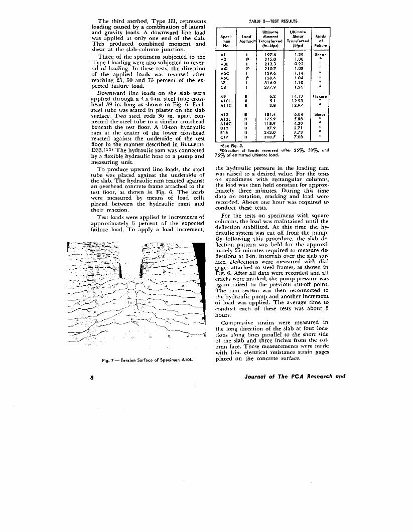
Fig. 7 — Tension Surface of Specimen AIOL.
Speci-menNo.
AlA2A3LA4LA5CA6CB7C8
A9A1OLA1l C
A12A13LA14CD15B16C17
TABLE 3—TEST RESULTS
LoadMethod
Ilb
Ilb
Ilb
II
IIIIII
IllIllIll111IllIll
UltimateMoment
lrronsferrec[in.-kipd
197.6215.0213.3210.7139.6150.6316.0277.9
6.25.13.8
181.4175.9118.9
87.9242.0218.7
UltimateShear
rr.ansferrec[kips)
1.291.080.921.081.141.041.101.26
14.1312.9312.97
6.045.884.302.717.737.08
Modeof
Faihm
ShearII“u.““.
Flexure“.
Shear.II““.
‘See Fig. 5.bDirection of loads reversed after 25% 50% and
75~o of estimated ultimate load.
the hydraulic pressure in the loading ramwas raised to a desired value. For the testson specimens with rectangular columns,the load was then held constant for approx-imately three minutes. During this timedata on rotation, cracking and load wererecorded. About one hour was required toconduct these tests.
For the tests on specimens with squarecolumns, the load was maintained until thedeflection stabilized. At this time the hy-draulic system was cut off from the pump.By following this procedure, the dab de-flection pattern was held for the approxi-mately 25 minutes required to measure de-flections at 6-in. intervals over the slab sur-face. Deflections were measured with dialgages attached to steel frames, as shown inFig. 6. After all data were recorded and allcracks were marked, the pump pressure wasagain raised to the previous cut-off point.The ram system was then reconnected tothe hydraulic pump and another incrementof load was applied. The average time toconduct each of these tests was about 5hours.
Compressive strains were measured inthe long direction of the slab at four loca-tions along lines parallel to the short sideof the slab and three inches from the col-umn face. These measurements were madewith 1-in. electrical resistance strain gagespiaced on the concrete surface.
8 Journal of The PCA Research and
Test Result~
The ultimate moments and shears trans-ferred from the slab to the column at thefailure load of each test specimen are givenin Table 3. The values include appliedload and weight of the slab and loadingequipment.
It may be noted that the ultimate mo-ments transferred by Specimens Al and AZ,A3L and A4L, and A5C and A6C indicatea small spread of test results of 10 percentor less for similar conditions. The second ofeach of these pairs was subjected to thesame type of loading as the first, except forreversal of loading. In two of the threeduplications, the ultimate moment afterreversals was higher than without reversals.
All of the test specimens except A9,AIOL, and Al lC failed in shear. Thesethree specimens were subjected to the Type11 loading and failed in flexure, as if theslab were acting as a wide beam. In allthree tests the ultimate moment sustainedby the slab was greater than the flexuralcapacity computed according to the 1963ACI Building Codet 10) assuming the fullwidth of the slab along a section ad jscentto the column face to be effective. The ulti-mate flexural strengths of Specimens A 10Land Al IC, with holes parallel to the longand short sides of the column, respectively,were very nearly equal and only about 10percent less than that of the comparableslab without holes, Specimen A9. A photo-graph of the tension side of the slab ofSpecimen A1OL after failure is shown inFig. 7.
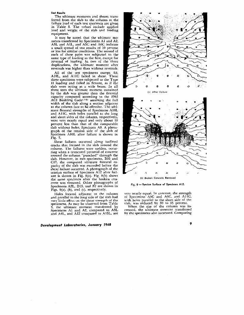
Shear failures occurred along inclinedcracks that formed in the slab around thecolumn. The failure$ were sudden, occur-ring when a truncated pyramid of concretearound the column “punched” through theslab. However, in two specimens, B16 andC 17, the computed ultimate flexural ca-pacity of the slab was exceeded before theshear failure occurred. A photograph of thetension surface of Specimen A12 after fail-ure is shown in Fig. 8(a). Fig. 8(b) showsthe same specimen after the broken con-crete was removed. Other photographs ofSpecimens A3L, D 15, and B7 are shown inFigs. 9(a), (b), and (c), respectively.
Holes located adjacent to the columnand parallel to the long side of the slab hadvery little effect on the shear strength of thespecimens. As may be observed from Table3, the ultimate moment transferred bySpecimens A 1 and AZ, compared to A3Land A4L, and A12 compared to A13L, are
(o) After Failure
e
mP -) c) a
(b) Broken Concrete Removed
Fig. 8 — Tension Surface of Specimen A12.
very nearly equal. In contrast, the strengthof Specimens A5C and A6C, and A14C,with holes parallel to the short side of theslab, was reduced by 30 to 35 percent.
When the size of the column was in-creased, the ultimate moment transferredby the specimens also increased. Comparing
Development Lobora+ories, January 1968 9
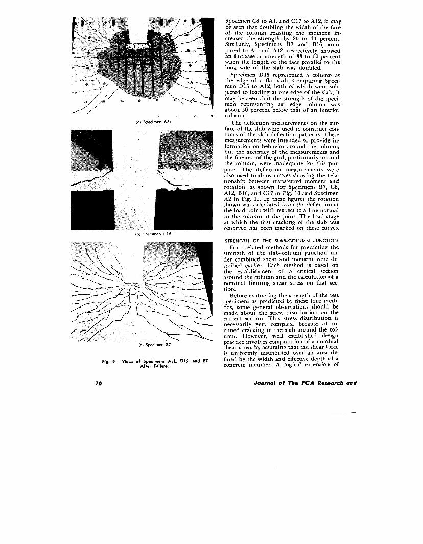
7 e. a(a) Specimen A3L
m.m(b) Specimen DI 5
Fig. 9—ViQws of Specimens A3L, DI 5, and B7After Failure.
Specimen C8 to Al, and C17 to A12, it maybe seen that doubling the width of the faceof the column resisting the moment in-creased the strength by 20 to 40 percent.Similarly, Specimens B7 and B 16, com-pared to Al and A 12, respectively, showedan increase in strength of 33 to 60 percentwhen the length of the face parallel to thelong side of the slab was doubled.
Specimen D 15 represented a column atthe edge of a flat slab. Comparing Speci-men D 15 to A12, both of which were sub-jected to loading at one edge of the slab, itmay be seen that the strength of the speci-men representing an edge column wasabout 50 percent below that of an interiorcolumn.
The deflection measurements on the sur-face of the slab were used to construct con-tours of the slab deflection patterns. Thesemeasurements were intended to provide in-formation on behavior around the column,but the accuracy of the measurements andthe fineness of the grid, particularly aroundthe column, were inadequate for this pur-pose. The deflection measurements werealso used to draw curves showing the rela-tionship between transferred moment androtation, as shown for Specimens B7, C8,A12, B16, and C17 in Fig. 10 and SpecimenA2 in Fig. 11. In these figures the rotationshown was calculated from the deflection atthe load point with respect to a line normalto the column at the joint. The load stageat which the first cracking of the slab wasobserved has been marked on these curves.
STRENGTH OF THE SLAB-COLUMN JUNCTION
Four related methods for predicting thestrength of the slab-column junction un-der combined shear and moment were de-scribed earlier. Each method is based onthe establishment of a critical sectionaround the column and the calculation of anominal limiting shear stress on that sec-tion.
Before evaluating the strength of the testspecimens as predicted by these four meth-ods, some general observations should bemade about the stress distribution on thecritical section. This stress distribution isnecessarily very complex, because of in-clined cracking in the slab around the col-umn. However, well established designpractice involves computation of a nominalshear stress by assuming that the shear forceis uniformly distributed over an area de-fined by the width and effective depth of aconcrete member. A logical extension of
70 Journal of The PCA Research and

this practice is to assume that an unbal-anced moment creates additional shearingstresses which, over part of the critical sec-tion, add to the direct shear stresses. Themaximum combined shear stress thus ob-tained then becomes the criterion on whichthe strength of the junction is based.
Actually, only part of the total momenttransferred at the slab-column junctioncreates shearing stresses that add to the di-rect shear stresses. Part of the moment isresisted by flexural stresses acting on sidesAB and CD of the critical section shown inFig. 1. The remainder of the moment isresisted by both vertical and horizontalshear stresses acting on sides BC and AD,and by vertical shear stresses acting on sidesAB and CD. AII four methods assume thatthe vertical shear stresses vary linearly withthe distance from the centroidal axis. Thisassumption leads to expressions having theform of Eqs. (l), (2), (3), and (4). Theseequations differ primarily in location ofthe critical section and the portion of themoment assumed to produce the addedshear stress.
Comparison of Measured andComputed Strengths
Both Moe’s method and the method rec-ommended by Committee 326 assume thatthe added shear stress is proportional to thetotal moment transferred, i.e., to KM. InEq. (2), ~. is equal to /x2dA taken overthe entire area of the critical section, where-
as in Eq. (3), ~C is equal to Jx2dA takenover the entire area plus jyzdA taken oversides BC and DA of the critical section. Inthese integrals x and y are horizontal andvertical distances, respectively, from thecentroidal axis to an element of area dA.Thus KM in Eq. (2) is that part of thetotal moment which produces only verticalshear stress, while KM in Eq. (3) is that
Fig. 10 — Moment-Rotation Curves.
$tA’I
~“ t
n“ fId
E 1oo- -Y03
5(Y1-1-
Crack Observedfizoz
I [ 1 1-0.03 -0.02 -0.01 / 0.01
/0.02
ROTATION, RADIANS
/’
/’
/’/
--1oo
- --200
Fig. I I — Moment-Rotation Curve for A2.
part of the total moment which producesboth vertical and horizontal shearing stress.This does not explain the difference be-tween the K-values of 0.33 recommendedby Moe for use in Eq. (2) and 0.2 recom-mended by Committee 326 for use in Eq.(3). On the contrary, this reasoning wouldindicate that the K-value in Eq. (3) shouldbe greater than in Eq. (2).
Di Stasio and Van Buren’s method, andthe method in the 1963 ACI Building CodeCommentary, assume that the added shearstress is proportional to the total momenttransferred minus the moment resisted bysides AB and CD of the critical section, i.e.to (M — mA~ — mc~). Since the momentresisted by sides AB and CD is a predeter-mined quantity, shear stress is producedonly when M exceeds m*~ + mc~.
Di Stasio and Van Buren. In this evalua-tion of the strength of the test specimens,the Di Stasio and Van Buren method wasmodified to conform to the 1963 AGI Build-ing Code. Consequently, the shear workingstress was assumed to be 2 Y7., and thecritical section was taken at a distance
Development Laboratories, January 1968 11
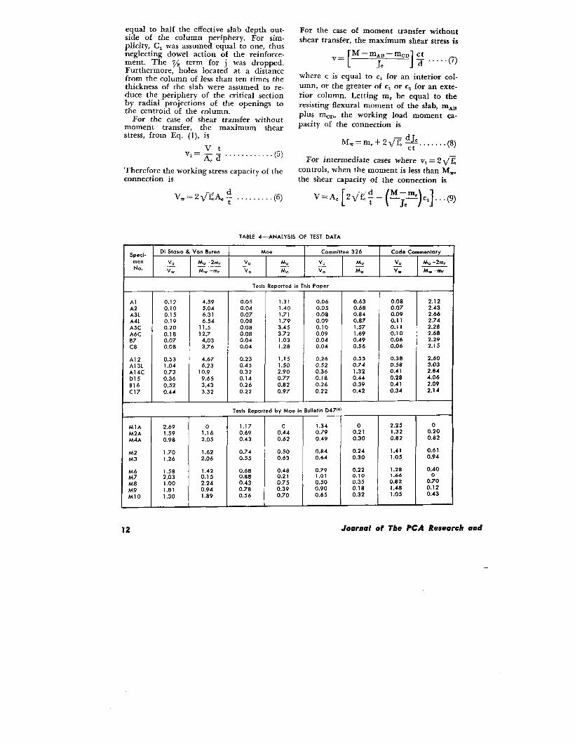
equal to half the effective slab depth out-side of the column periphery. For sim-plicity, Cl was assumed equal to one, thusneglecting dowel action of the reinforce-ment. The 7/8 term for j was dropped.Furthermore, holes located at a distancefrom the column of less than ten times thethickness of the slab were assumed to re-duce the periphery of the critical sectionby radial projections of the openings tothe centroid of the column.
For the case of shear transfer withoutmoment transfer, the maximum shearstress, from Eq. (l), is
Vt‘==~ ii”””””””””””’(5)
Therefore the working stress capacity of theconnection is
For the case of moment transfer withoutshear transfer, the maximum shear stress is
[M–mAB–%sI Ct
V=
J. 1 x . . ...(7)
where c is equal to c1 for an interior col-umn, or the greater of c1 or Cz for an exte-rior column. Letting m= be equal to theresisting flexural moment of the slab, mAB
plus mo~, the working load moment ca-pacity of the connection is
MW=mr+2~~ ~.... . ..(8)
For intermediate cases where v,= 2 ~~
controls, when the moment is less than MW,the shear capacity of the connection is
VW=2~zAc ; . . . . . . ...(6) V=A. [2ti~+- [~)c1](9)
TAtlLE 4—ANALYSIS OF TEST DATA
Speci-Di Stasio & Van Buren Moe Committee 326 Code Commentary
men v. M, –2rnr v“ q v. MuNo.
v.
v.
M. –2m,
Mw –m, < Mo v. Mo E Mw –m,
Tests Reported in This Paper
Al 0.12 4.59 0.05 1.31 0.06 0.63 0.08 2.12A2 0.10 5.04 0.04 1.40 0.05 0.68 0.07 2.43A3L 0.15 6.31 0.07 1.71 0.08 0.84 0.09 2.66A4L 0.19 6.54 0.08 1.79 0.09 0.87 0.11 2.74A5C 0.20 11.5 0.08 3.45 0.1o 1.57 0.11 2.28A6C 0.18 12.7 0.08 3.72 0.09 1.69 0.10 2.6807 0.07 4.03 0.04 1.03 0.04 0.49 0.06 2.29C8 0.0s 3.76 0.04 1.28 0.04 0.56 0.06 2.15
A12 0.53 4.67 0.23 1.15 0.26 0.55 0.38 2.60
A13L 1.04 6.23 0.45 I .50 0.52 0.74 0.58 3.03
A14C 0.73 10.9 0.32 2.9o 0.36 1.32 0.41 2.84
D15 0.36 9.65 0.14 0.77 0.18 0.44 0.28 4.06
B16 0.52 3.43 0.26 0.82 0.26 0.39 0.41 2.09
C17 0.44 3.32 0.22 0.97 0.22 0.42 0.34 2.14
Tests Reported by Moe in Bulletin D47@)
MIA 2.69 0 1.17 0 1.34 0 2.25 0
M2A 1.59 1.16 0.69 0.44 0.79 0.21 1.32 0.20
M4A 0.98 2.o5 0.43 0.62 0.49 0.30 0.82 0.82
M2 1.70 1.62 0.74 0.50 0.84 0.24 1.41 0.61
M3 1.26 2,06 0.55 0.63 0.64 0.30 1.05 0.94
M6 1.58 1.42 0.68 0.48 0.79 0.22 1.28 0.40
M7 2.03 0.15 0.68 0.21 1,01 0.10 1.66 0
M8 1.00 2.24 0.43 0.75 0.50 0.35 0.82 0.70
1.81 0.94 0.78 0.39 0.90 0.18 1.48 0.12
so 1.30 1.89 0.56 0.70 0.65 0.32 1.05 0.43
12 Journal of The PCA Research and

Combining Eqs. (6), (8), and (9) gives thestrength interaction equation
v M–m,z’l– MW – m=
. . . . . ..(10)
Now assuming that the working shear, V,and moment, M, for the test specimens areone half of the ultimate shear, VU, and mo-ment, MU, respectively, Eq. (10) becomes
v Mu–2mr<=2– MW–m, ””””””
.(11)
The values of Vu/VW and (Mu – 2 m,)/(I& – m,) for the test specimens listed inTables 1 and 3 are given in Table 4. Testspecimens that failed in flexure were notincluded. In calculating m, for the testspecimens with holes, it was assumed thatthe reinforcement running through theholes was stressed to its working stress limit.These vaIues are ako pIotted as an inter-action diagram in Fig. 12. It may be seenthat all of the experimental points are out-side of the dashed line that representsEq. (11). This indicates that the working
shear stress of 2 ~?c was conservative for asafety factor of 2.
Johannes Moe. In Moe’s method, thecritical section is assumed to be locatedadjacent to the column periphery. Theultimate shear stress is calculated from Eq.(2). For the case of shear transfer withoutmoment transfer, the ultimate shear ca-pacity of the connection is
VO=VUA . . . . . . . . . . . . (12)
&Vw
3 - A Author< tests
L Holesc1E Edge Column
2 q\*
I -
I ~~ ,J
&\ . .
\*. .\
p
\ . .\
I&
\\ -. A :.
\o - ..-
0 2 3 4 5 ~:
Mu-2mr #[
Mw–mr~–
Fig. 12 — Working Stress Method Recommended byDi S+asio and Van Buren.
DeveIopmenf Laboratories, January 1968
21
I . Moejtests I1.5
t
- Auihors’ tests
k} f+Oles 1
&l 1E Edge Column
Vo \*\*. ;
\’0.5 \ . .
Y“ -L\. AcEA\ - “
I‘+/
co *A , .-L
o 05 15 2 25 31
~ ::.
Mo
Fig. 13— Ultimate Strength MethodRecommended by Moe
where vu was assumed equal to (9.23 – 1.12
r/d) ~Z since r/d was less than 3 in all ofthe tests in Tables 1 and 3. Similarly, forthe case of moment transfer without sheartransfer, the ultimate moment capacity ofthe connection is
MO= ;~c— . . . . . . . . . ..(13)
where c is equal to c, for an interior col-umn or the greater of c1 or Cz for an ex-terior column.
For intermediate cases where v, controls,the ultimate shear capacity of the connec-tion is
[
KM. C
1V.=AC v.–- . . . .
1..(14)
Combining Eqs. (12), (13), and (14) givestie strength equation
The values of V./VO and Mu/Mo, assumingK equal to IA for tests reported in thispaper and in BULLETIN D47, ( G) are givenin Table 4 and plotted in Fig. 13. It maybe seen that Moe’s method conservativelypredicted the ultimate strength of all butone of these tests.
Committee 526. The method of com-puting the strength of the slab-column junc-tion recommended by Committee 326 leadsto an equation similar to Moe’s, The criti-cal section is assumed to be located a dis-tance d/2 from the face of the column. The
- 4 @%. Values ofultimate shear stress, VU, NV~VO and MJMO, assuming K equal to
13
2
[
. Moe’s tes!s
15 - Authors’ tests
‘co 0.5 1.5 2 25 3
Fig. 14 — Ultimate Strength Method Recommendedby Commit+ee 326 [K= 0.2)
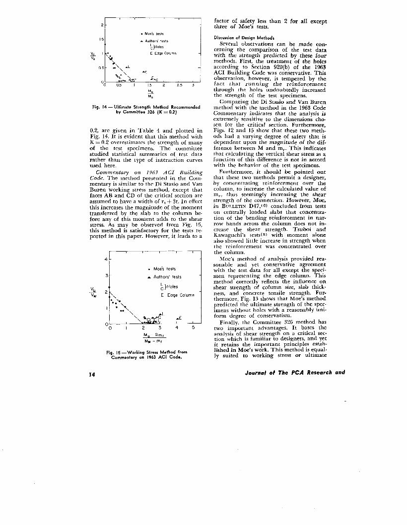
0.2, are given in Table 4 and plotted inFig. 14. It is evident that this method withK = 0.2 overestimates the strength of manyof the test specimens. The committeestudied statistical summaries of test datarather than the type of interaction curvesused here.
Commentary on 1963 A C[ BuildingCode. The method presented in the Com-mentary is similar to the Di Stasio and VanBuren working stress method, except thatfaces AB and CD of the critical section areassumed to have a width of t-z+ 3t. In effectthis increases the magnitude of the momenttransferred by the slab to the column be-fore any of this moment adds to the shearstress. As may be observed from Fig. 15,this method is satisfactory for the tests re-ported in this paper. However, it leads to a
4
t . Moe’s tests
‘t A Authors’ testsi
AL~ }Holes
E Edge Column
ALa., %-c -E
k
2 3 4 5
Mu– 2rnr
Mw–mr
Fig. 15 — Working Stress Method fromCommentary on 1963 ACI Code.
factor of safety less than 2 for all exceptthree of Moe’s tests.
Discussion of Design Methods
Several observations can be made con-cerning the comparison of the test datawith the strength predicted by these fourmethods. First, the treatment of the holesaccording to Section 920(b) of the 1963ACI Building Code was conservative. Thisobservation, however, is tempered by thefact that running the reinforcementthrough the holes undoubtedly increasedthe strength of the test specimens.
Comparing the Di Stasio and Van Burenmethod with the method in the 1963 CodeCommentary indicates that the analysis isextremely sensitive to the dimensions cho-sen for the critical section. Furthermore,Figs. 12 and 15 show that these two meth-ods had a varying degree of safety that isdependent upon the magnitude of the dif-ference between M and m,. This indicatesthat calculating the vertical shear stress as afunction of this difference is not in accordwith the behavior of the test specimens.
Furthermore, it should be pointed outthat these two methods permit a designer,by concentrating reinforcement over thecolumn, to increase the calculated value ofm,, thus seemingly increasing the shearstrength of the connection. However, Moe,in BULLETIN D47, tG) concluded from testson centrally loaded slabs that concentra-tion of the bending reinforcement in nar-row bands across the column does not in-crease the shear strength. Tsuboi andKawaguchi’s testsfs) with moment alonealso showed little increase in strength whenthe reinforcement was concentrated overthe column.
Moe’s method of analysis provided rea-sonable and yet conservative agreementwith the test data for all except the speci-men representing the edge column. Thismethod correctly reflects the influence onshear strength of column size, slab thick-ness, and concrete tensile strength. Fur-thermore, Fig. 13 shows that Moe’s methodpredicted the ultimate strength of the spec-imens without holes with a reasonably uni-form degree of conservatism.
Finally, the Committee 326 method hastwo important advantages. It bases theanalysis of shear strength on a critical sec-tion which is familiar to designers, and yetit retains the important princi pies estab-lished in Moe’s work. This method is equal-ly suited to working stress or ultimate
Journal of The PCA Research and
I I 1 1 1 1
2 -
. M& tesk
1.5- - Authors! tests
~} Holes
k,E Edge column
<% \*
<9*0.s \“
Y+A* AC-s L&L
o . A. +o 0.5 I 1.5 2 2.5 3 3.5
&u
%
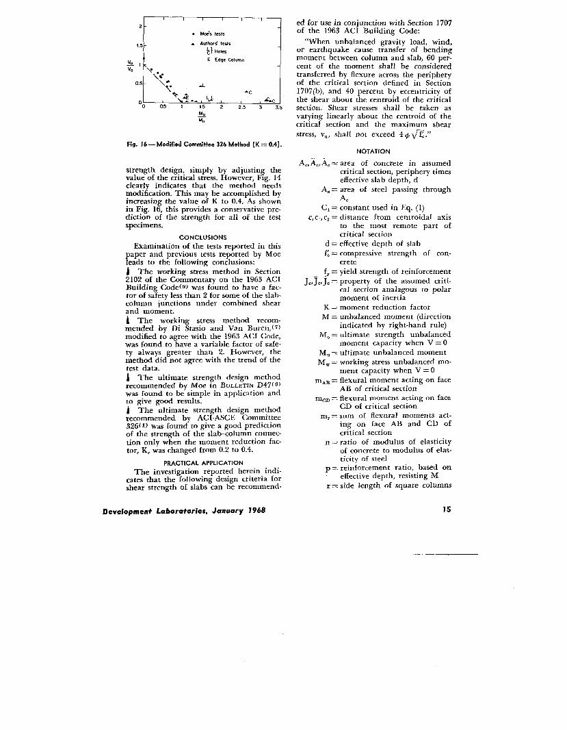
Fig. 16 — Modified Commit%. 326 Method [K= 0.4).
strength design, simply by adjusting thevalue of the critical stress. However, Fig. 14clearly indicates that the method needsmodification. This may be accomplished byincreasing the value of K to 0.4. As shownin Fig. 16, this provides a conservative pre-diction of the strength for all of the testspecimens.
CONCLUSIONS
Examination of the tests reported in thispaper and previous tests reported by Moeleads to the following conclusions:
j The working stress method in Section2102 of the Commentary on the 1963 ACIBuilding Code{ g> was found to have a fac-tor of safety less than 2 for some of the slab-column junctions under combined shearand moment.A The working stress method recom-mended by Di Stasio and Van Buren,(7)modified to agree with the 1963 ACI Code,was found to have a variable factor of safe-ty always greater than 2. However, themethod did not agree with the trend of thetest data.
1 The ultimate strength design methodrecommended by Moe in BULLETIN D47 f‘)was found to be simple in application andto give good results.i The ultimate strength design methodrecommended by ACI-ASCE Committee326(1) was found to give a good predictionof the strength of the slab-column connec-tion only when the moment reduction fac-tor, K, was changed from 0.2 to 0.4.
PRACTICAL APPLICATION
The investigation reported herein indi-cates that the following design criteria forshear strength of slabs can be recommend-
ed for use in conjunction with Section 1707of the 1963 ACI Building Code:
“When unbalanced gravity load, wind,or earthquake cause transfer of bendingmoment between column and slab, 60 per-cent of the moment shall be consideredtransferred by flexure across the peripheryof the critical section defined in Section1707(b), and 40 percent by eccentricity ofthe shear about the centroid of the criticalsection. Shear stresses shall be taken asvarying linearly about the centroid of thecritical section and the maximum shearstress, VU, shall not exceed 4 + ~~..”
NOTATION
A., &AC = area of concrete in assumedcritical section, periphery timeseffective slab depth, d
A,= area of steel passing throughAC
C,= constant used in Eq. (1)c, cl, Cz= distance from centroidal axis
to the most remote part ofcritical section
d = effective depth of slabf: = compressive strength of con-
cretef,= yield strength of reinforcement
J~,7,,J~ = property of the assumed criti-cal section analagous to polarmoment of inertia
K = moment reduction factorM = unbalanced moment (direction
indicated by right-hand rule)MO= ultimate strength unbalanced
moment capacity when V = OMu= ultimate unbalanced momentMm= working stress unbalanced mo-
ment capacity when V = OmA~ = flexural moment acting on face
AB of critical section
mc~ = flexural moment acting on face
CD of critical sectionm,= sum of flexural moments act-
ing on face AB and CD ofcritical section
n = ratio of modulus of elasticityof concrete to modulus of elas-ticity of steel
p = reinforcement ratio, based oneffective depth, resisting M
r = side length of square columns
Development Laboratories, January 1968

rl = width of face of column paral-lel to plane of M
rz = width of face of column per-pendicular to plane of M
t = thickness of slabV = shear
VO = ultimate strength shear capac-ity when M = O
V.= ultimate shearVW= working stress shear capacity
when M = Ov, vi, V2= vertical shear stress
Vu = ultimate shear stress
x = dimension of critical section asshown in Fig. 1
y = dimension of critical section asshown in Fig. 1
@ = capacity reduction factor usedin 1963 ACI Building Code
ACKNOWLEDGMENTS
The investigation reported herein wascarried out in the Structural Laboratory ofthe Portland Cement Association. Credit isdue to W. W. Berglund, B. W. Fullhart,W. H. Graves, W. Hummerich, and O. A.Kurvits for assistance in the manufactureand testing of the specimens.
REFERENCES
1. ACI-ASCE Committee 326, “Shear and DiagonalTension,” Journal of the American ConcreteInstitute, (January to March 1962); Proceedings,59, 1-30, 277-334, and 353-395 (1962).
Z RosenthaI, Israel, “Experimental Investigationof Flat Plate Floors,” Journal of the AmericanConcrete Institute (August 1959); Proceedings,56, 153-166 (1959-60).
‘3. Tsuboi, Yoshikatsu, and Kawaguchi, Mamom,“On Earthquake Resistant Design of Flat Slabsand Concrete Shell Structures, ” PROCEEDINGSOFmm SECOND WORLD CONFERENCE ON EARTHQUAKE
ENGINWXING, TOKYO AND KYOTO, JAPAN, Vol.HI. 1693-1708, UUly 1960).
4. Kreps, Robert R., and Reese, Raymond C., Dis-cussion of a paper by Di Stasio, J., and Van
Buren, M. P.: “’Transfer of Bending MomentBetween Flat Plate Floor and Column,” Journalof the A merican Concrete Institute (March 1961);Proceedings, 57, 1261-1263 (1960-61).
5. Frederick, G. R. and Pollauf. F. P., “Experi.mental Determination of tbe Transmission ofColumn Moments to Flat Plate Floors.” Un-
6.
7.
8.
9.
publisbed Report of University of Toledo, To.ledo, Ohio (May 1959).
Moe, Johannes, “Shearing Strength of Rein-forced Concrete Slabs and Footings Under Con-centrated Loads, ” Development DepartmentBulletin D47, Portland Cement Association(April 1961), 130 pages.
Di Stasio, Joseph, and Van Buren, M. P.,“Transfer of Bending Moment between FiatPlate Floor and Column,” Journal of the Ameri-can Concrete Institute (September 1960); Pro-ceedings 57, 299-314 (1960-61).
ACI STANDAIZJ BUILDING CODE REQUIREMENTS FORREINFORCED CONCIWTE (ACI 318-56), Journal ofthe A rnerican Concrete Institute (May 1956);Proceedings 52, 913-986 (1955-56).
ACI Committee 318, COMMENTARY ON BIJILCIINGCODE REQUIREMENTS FOR REINFORCEDCONCRETE(ACI 318-62), Publication SP-10, American Con-crete Institute, Detroit, Michigan (1965), 91pages. Also printed in ACI MANCIALOF CON-
;RE”m PFLK%E, PART 2, pp. 318-145 to 318-239(1967).
10. AC1 STANDATW BUILDING CODE REQUIREMENTS FORREINFORCED CONCRETE (ACI 318-63), AmericanConcrete Institute, Detroit, Michigan (June1963), 144 pages.
1I. ASTM Designation: A 15-66, “Standard Specifi-cations for Billet-Steel Bars for Concrete Rein-forcement, “American Society for Testing andMaterials, Philadelphia, Pennsylvania.
12. ASTM Designation: A 305-65, “Standard Speci-fications for Minimum Requirements for theDeformations of Deformed Steel Bars for Con-crete Reinforcement.” As in Reference 11.
13. Hognestad, Eivind, Hanson, N. W., Kriz, Ladis-lav B., and Kurvits, Otto A., “Facilities andTest Methods of PCA Structural Laboratory,”papers under various titles in Journal of thePCA Research and Development Laboratories,1, No. I, 12-20, 40-44 (January 1959); 1, No. 2,30-37 (May 1959); 1, No. 3, 35-41 (September1959); reprinted as PCA Deuelo@nent Depart-ment Bulletin D33.
PCA .R&D.Ser.1312-2
16 Journal of The PCA Research and Development Loborotories, January 1968

Bulletins Published by the
Development Department
Research and Development Laboratories
of the
Portland Cement Association
DIOO—’’Index of Development Department Bulletins D1-D99. Annotated List with Authorand Subject Index.”
Published by Portland Cement Association, Research and Development Laboratories,Skokie, Illinois (1967).
DIO1—’’Rotational Capacity of Hinging Regions in Reinforced Concrete Beams, ” by ALANH. MATTOCK.
Reprinted from FLEXURALMSCSiANICSOF REINFORCEDCONCRETE,Proceedings of the Inter-national SU?nposiwn, Miami, Fla. (November 1964) pages 143-181, joint sponsorship.Copyrighted 1965 by American Society of Civil Engineers.
D102—’’Tests of Partially Prestressed Concrete Girders,” by DONALDD. MAGURAand EXVINDHOGNESTAD.
Reprinted from the Journal of the Structural Division, Proceedings of the AmericanSocietu of Civil Engineers, Proc. Paper 4685, 92, ST 1, 327-350 (February 1966).
D103—’’Influence of Size and Shape of Member on the Shrinkage and Creep of Concrete,”by TORBENC. HANSEN and ALAN H. MATTOCK.
Reprinted from Journal of the American Concrete Institute (February 1966): Proceed-ings 63, 267-29o (1966).
D104-’’CasiniPlacece Concrete Residences With Insulated Walls,” by HARRY L. SCOGGIN.Reprinted from Journa~ of the PCA Research and Development Laboratories, 8, No. 2,21-29 (May 1966).
D105—’’Tensile Testing of Concrete Block and Wall Elements,” by RICHARD O. HEDsTRoM.
Reprinted from Journal of the PCA Research and Development Laboratories, 8, No. 2,42-52 (May 1966).
D106—’’High Strength Bars as Concrete Reinforcement, Part 8. Similitude in FlexuralCracking of T-Beam Flanges,” by PAUL H. KAAR.
Reprinted from Journal of the PCA Research and Development Laboratories, 8, No. 2,2-12 (May 1966).
D107—’’Seismic Resistance of Reinforced Concrete—A Laboratory Test Rig,” by NORMANW. HANSON and HAROLD W. CONNER.
Reprinted f mm Journal of the PCA Research and Development Laboratories, 8, No. 3,2-9 (September 1966).
D108—’’Rotational Capacity of Reinforced Concrete Beams,” by W. GENE CORLEY.Reprinted from Jaurnat of the Structural Division, Proceedings of the American Sa-tiety of C!ioit Engineers, Proc. Paper 4939, 92, ST5, 121-146 (October 1966).
DI09—’’Laboratory Studies of the Skid Resistance of Concrete,” by G. G. BALMER andB. E. COLLEY.
Reprinted from ASTM Jou?’nat of Materials L No. 3, 536-559 (September 1966).
Dl10—’’Connections in Precast Concrete Structures—Column Base Plates;’ by R. w.LAFRAUCH and D. D. MAGURA.
Reprinted from Journal of the Prestressed Concrete Institute, 11, No. 6, 16-39 (De-cember 1966).
Dill—’’Laboratory Study of Shotcrete,” by ALBERT LITVIN and JOSEPH J. SHIDELER.
Reprinted from Symposium cm Shotcreting, American Concrete Institute, Paper No.13 in Publicatic.n SP-14, 165-184 (1966).
Dl12—’’Tests on Soil-Cement and Cement-Modified Bases in Minnesota.’” by TO.WJORN J.LARSEN.
Reprinted fmm Journal of the PCA Research and Development Laboratories. 9. No. 1.25-47 (January 1967).

Dl13—’’Structural Model Testing—Reinforced and Prestressed Mortar Beams.” by DON-ALLID. MAGURA.
Reprinted from Journal of the PCA Research and Deuefopment Laboratories, 9, No. 1,2-24 (January 1967).
Dl14-’’GeneraI Relation of Heat Flow Factors to the Unit Weight of Concrete, ” byHAROLD W. BREWER.
Reprinted from Journat oj the PC!A Research and Development Laboratories, 9, No. 1,48-60 (January 1967).
D115—” Sand Replacement in Structural Lightweight Concrete--sintering Grate Aggre-gates,” by DON6LD W. PFEIFER and J. A. HANSON.
Reprinted from Journa[ of the American Concrete Institute (March, 1967); Proceedings64, 121-127 (1987) .
D116—” Fatigue Tests of Reinforcing Bars—Tack Welding of Stirrups: by KENNZTR T.BURTON and EIVIND HOGNESTAD.
Reprinted from Journat of the American Concrete Institute (May, 19S7); Proceedings64, 244-252 (1967).
D117—” Connections in Precast Concrete Structures—Effects of Restrained Creep andShrinkage,” by K. T. BURTON, W. G. CORLEY, and E. HOGNESTAD.
~9&r#ted from Journal of the Prestressed Concrete Institute, 12, No. 2, 16-37 (April,
Dl18—’’CasiniPlacece Concrete Residences with Insulated Walls-Influence of Shear Con-nectors on Flexural Resistance,” by HARRY L. SCOGGINand DONALDW. PFSIFSR.
Reprinted from Journal of the PCA Research and Devetafnnent Laboratories, 9, No. 2,2-7 (May 1967).
Dl19—’’Fatigue of Soil-Cement,” by T. J. LARSEN and P. J. NUSSBAUM.
Reprinted from Journal of the PCA Research and Development Laboratories, 9, No 2,37-59 (May 1967).
D120-’’Sand Replacement in Structural Lightweight Concrete-Splitting Tensile Strength,”by DONALDW. PFEIFER.
Reprinted from Joumat of the American Concrete Institute (July 1967); Proceedings 64,384-392 (1967).
D121—’’Seismic Resistance of Reinforced Concrete Beam-Column Joints,” by NORMANW. HANSON and HAROLDW. CONNER.
Reprinted from Journal of the Structural Division, Proceedings of the American Societyof Civil Engineers, Proc. Paper 5537, 93, ST5, 533-560 (October 1967).
D122—’’Precast Rigid Frame Buildings—Test of Scarf Connections: by PAUL H. KAAR andHAROLD W. CONNER.
Reprinted from Journal of the PCA Research and Deve@pment Laboratories, 9, No. 3.34-42 (September 1967).
D123—’’Precast Rigid Frame Buildings—Component Tests,” by HAROLDW. CONNER andPAUL H. KAAR.
Reprinted from Journal of the PCA Research and Development Laboratories, 9, No. 3,43-55 (September 1967).
D124-’’Aggregate Interlock at Joints in Concrete Pavements,” by B. E. COLLEYand H. A.HUMPHREY.
Reprinted from Highway Research RECORD,Number 159, 1-1S (1967).
D125—’’Cement Treated Subbases for Concrete Pavements,” by L. D. CEILDS.Reprinted from Highway Research RECOSD,Number 189, 19-43 (1967).
D126—’’Sand Replacement in Structural Lightweight Concrete—Freezing and ThawingTests,” by DONALD W. PFEIFER.
Reprinted from Journal of the American Concrete lnsSttute (November 1s67); Pn%eed-ings 64, 735-744 ( 1967).
D127—’ ‘Ultimate Torque of Reinforced Rectangular Beams,” by TrioMAs T. C. HSU.
Reprinted from Jmmal of the st~ctural Di~~, proceedings Of the American S*ctety of Civil Engineers, Proc. Paper 5814, 94, ST2, 4S5-S10 (February 1966).
D128--’’Sand Replacement in Structural Lightweight Concrete-Creep and ShrinkageStudies,” by DONALDW. PFEIFER.
Reprinted from Journat of the American Concrete Institute (February 1968); Pro-ceedings, 65, 131-140 (1968).
D129-’’Shear and Moment Transfer Between Concrete Slabs and Columns,” by NORMANW. HANSON and JonN M. HANSON.
Reprinted from Journal of the PCA Research and Development Laboratories, 10, No.1, 2-16 (January 1968)
Printed in U.S.A.
“Shear and Moment Transfer BetweenConcrete Slabs and Columns”
uKEY WORDS: columns (structural); concrete slabs; cyclic loads; flat plates (concrete); Iflexural tests; openings; punching shea~ shear tests; structural analysis
ISYNOPSIS: The strength of flat slabs near columns was investigated hy 17 tests in-volving combined shear and unbalanced moment loadings. Sixteen reinforced concrete isIa&cOlumn specimens containing square or rectangular interior columns and one IsPecimen with a square edge cOlumn were tested. NarrO~ rectangular holes werelocated adjacent to the columnsin eight of the specimens. Reversals of loading simulat-
:ing earthquake effects were applied to three of the specimens. Four design methods
1for shear strength, presented by DiStasio and Van Buren, Jobannes Moe, ACI-ASCE
ICommittee 326, and the Commentary on the 1963 ACI Building Code, are evaluatedIin terms of Moe’s data and test data reported herein. A modification of the Committee
326 method is recommended for practical design. 1IIII
REFERENCE: Hanson, Norman W., and HansOn, JOhn M.i Jowwal Of the pCA ResearchIand Development Laboratories (Portland Cement Association, U.S.A.), Vol. 10, No. 1,
January 1968, pp. 2-16; PCA Development Department Bulletin D129. III
“Shear and Moment Transfer Between I
Concrete Slabs and Columns” +KEY WORDS: colurrms (structural); cOncrete slabs; cyclic 10ads; ffat plates (cOncrete):
flexural tests; openings; punching shear; shear tests; structural analysis II
SYNOPSIS: The strength of flat slabs near columns was investigated by 17 tests ill- ivolving combined shear and unbalanced moment loadings. Sixteen reinforced concrete Islab-column specimens containing square or rectangular interior columns and nnc Ispecimen with a square edge column were testecl. Narrow mctan~rr]ar holes were Ilocated adjacent to the columns in eight of the specimens. Reversals of loading simulat- 1ing earthquake effects were applied to three of the specimcus. Four design methodsfor shear strength, presente(l by Di Stasio an(l Van Buren, Jobannes Moe, ACI-ASCE iCommittee 326, and the Commentary on the 1963 ACI Building Cmle, arc evaluated Iin terms of Moe’s data and test data reported herein. A modification nf the Cummittee I326 method is recommended for practical design. I
III
REFERENCE: Hanson, Norman W., and HansOn. J(Jhn M., .lour?za~ Of the ~CA l{e.$earcll Iand Development Laboratories (Portland Cement Association, U.S.A.), VO1. 10. No. 1,January 1968, pp. 2-16; PCA Deuelop)uent Department Bulletin 1)129.
III
“Shear and Moment Transfer BetweenI
Concrete Slabs and Columns”I
KEY WORDS: columns (structural); concrete slabs; cyclic loads; flat plates (concrete);I
ffexural tests; openings; punching shear; shear tests; structural analysisII
SYNOPSIS: The Strewfr of ffat slabs near cOlumns was investigated bY 17 ‘ests ‘*1- 1
volving combined shear and unbalanced moment loadings. Sixteen reinforced concrete I
slab–column specimens containing square or rectangular intel-ior columns and one I
specimenwitha square edge column were tested. Narrow rectangular holes were I
located adjacent to the columns in eight of the specimens. Reversals of loading simulat- 1ing earthquake effects were applied to three of the specimens. Four design methods I
for shear strength, presented by Di Stasio and Van Buren, JOhannes MOe, ACI-ASCE I
Committee 326, and the Commentary on the 1963 ACI Building Code, are evaluated I
in terms of Moe’s data and test data reported bercin. A modification of the Committee I326 method is recommended for practical design. I
1I
REFERENCE: Hanson, Norman W., and Hanson, John M., Journal of the PCA ResearchII
and Develo@ent Laboratorie.~ (Portland Cement Association, U.S.A.), Vol. 10, No. I, IJanuary 1968, pp. 2-16; PCA Development Departtnerlt Bulletin D129. I
1