Shared Access Networks - Computer Sciencehzhang/courses/4290/Lectures/2-1 - sharedMedia… ·...
69
Shared Access Networks Acknowledgement: this lecture is partially based on the slides of Dr. Larry Peterson Direct link networks: point-to-point links shared access networks Problem: physically connecting hosts Hongwei Zhang http://www.cs.wayne.edu/~hzhang
Transcript of Shared Access Networks - Computer Sciencehzhang/courses/4290/Lectures/2-1 - sharedMedia… ·...
Shared Access Networks
Acknowledgement: this lecture is partially based on the slides of Dr. Larry Peterson
Direct link networks:� point-to-point links� shared access networks
Problem: physically connecting hosts
Hongwei Zhang
http://www.cs.wayne.edu/~hzhang
Key issue?
Efficient, fair access control
Outline
� Bus (Ethernet)
� Token ring (FDDI)
� Wireless (802.11)
� Discussion
Outline
� Bus (Ethernet)
� Token ring (FDDI)
� Wireless (802.11)
� Discussion
Ethernet Overview
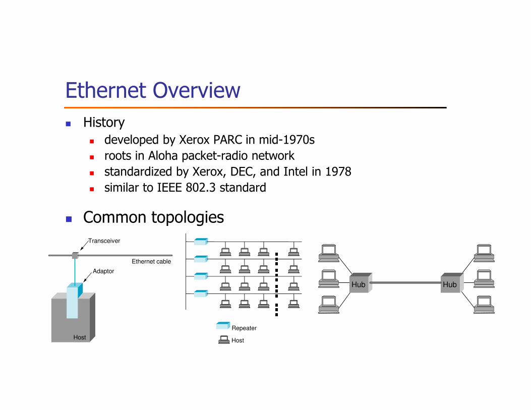
� History� developed by Xerox PARC in mid-1970s� roots in Aloha packet-radio network� standardized by Xerox, DEC, and Intel in 1978� similar to IEEE 802.3 standard
� Common topologiesTransceiver
Ethernet cable
Adaptor
Host
Repeater
Host
■■■■■■■■■■■■ Hub Hub
Ethernet (contd.)
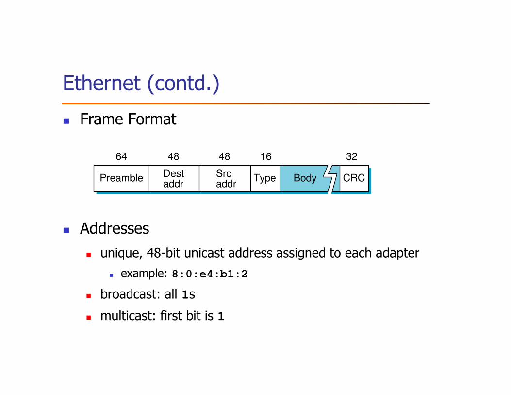
� Frame Format
� Addresses
� unique, 48-bit unicast address assigned to each adapter
� example: 8:0:e4:b1:2
� broadcast: all 1s
� multicast: first bit is 1
Destaddr
64 48 32
CRCPreamble Srcaddr
Type Body
1648
Ethernet (contd.)
� Bandwidth: 10Mbps, 100Mbps, 1Gbps
� Length: 2500m (500m segments with 4 repeaters)
� CSMA/CD� carrier sense� multiple access� collision detection
� Challenge: how to design distributed algorithm for efficient, fair
channel access?
Transmit Algorithm
� If line is idle…
� send immediately
� upper bound message size of 1500 bytes
� must wait 9.6us between back-to-back frames � To allow for receiver to be ready for the next reception
� 96 bits (minimum # of bits transmitted in the presence of collision) time for 10Mbps Ethernet
� If line is busy…
� wait until idle and transmit immediately
� called 1-persistent (special case of p-persistent)
Algorithm (contd.)
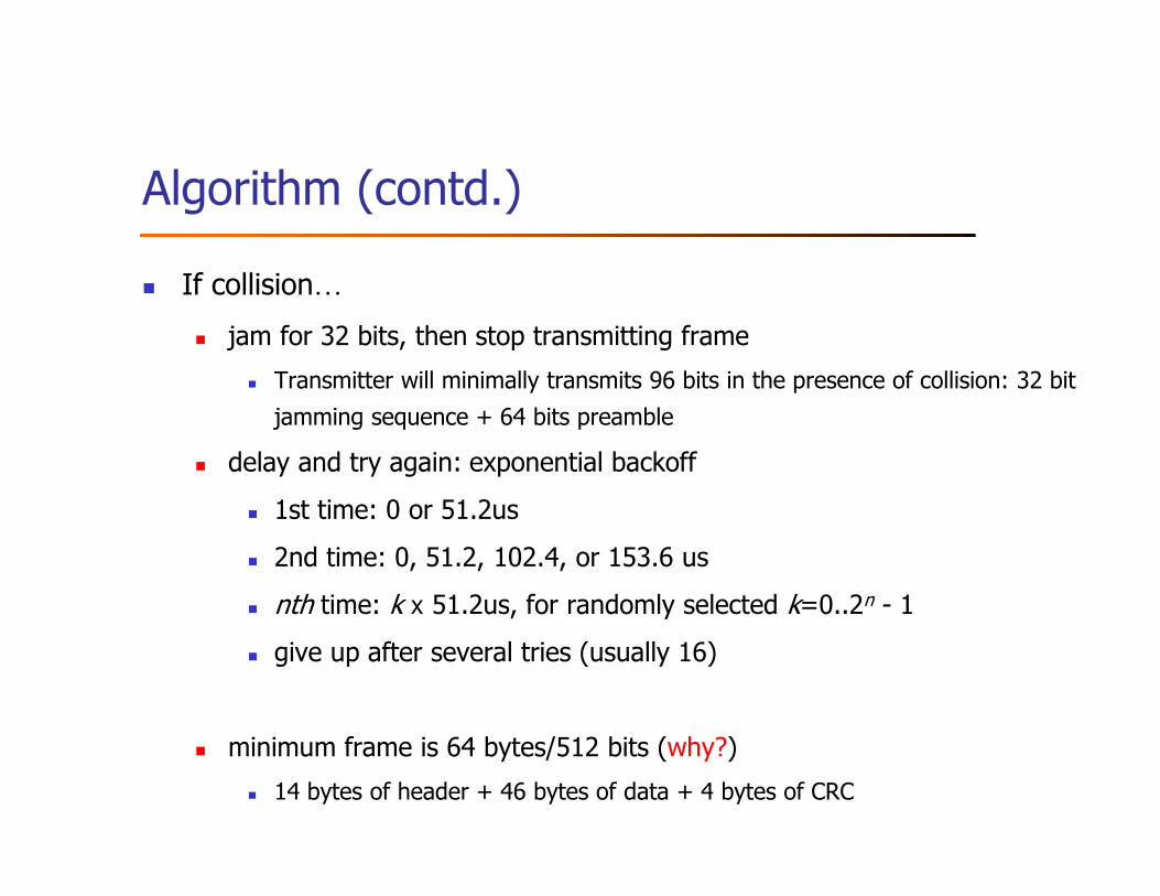
� If collision…
� jam for 32 bits, then stop transmitting frame
� Transmitter will minimally transmits 96 bits in the presence of collision: 32 bit
jamming sequence + 64 bits preamble
� delay and try again: exponential backoff
� 1st time: 0 or 51.2us
� 2nd time: 0, 51.2, 102.4, or 153.6 us
� nth time: k x 51.2us, for randomly selected k=0..2n - 1
� give up after several tries (usually 16)
� minimum frame is 64 bytes/512 bits (why?)
� 14 bytes of header + 46 bytes of data + 4 bytes of CRC
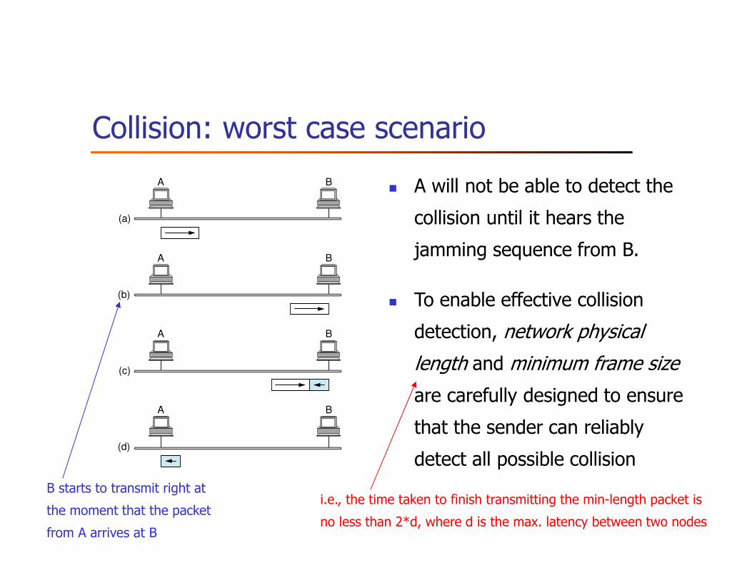
Collision: worst case scenario
(a)
(b)
(c)
A B
A B
A B
A B
(d)
� A will not be able to detect the
collision until it hears the
jamming sequence from B.
� To enable effective collision
detection, network physical
length and minimum frame size
are carefully designed to ensure
that the sender can reliably
detect all possible collision
i.e., the time taken to finish transmitting the min-length packet is
no less than 2*d, where d is the max. latency between two nodes
B starts to transmit right at
the moment that the packet
from A arrives at B
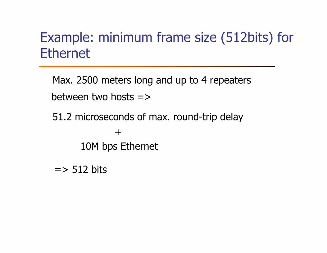
Example: minimum frame size (512bits) for Ethernet
Max. 2500 meters long and up to 4 repeaters
between two hosts =>
51.2 microseconds of max. round-trip delay
+
10M bps Ethernet
=> 512 bits
Outline
� Bus (Ethernet)
� Token ring (FDDI)
� Wireless (802.11)
� Discussion
Token Ring Overview
� Examples
� 4Mbps/16Mbps IEEE 802.5 (based on earlier IBM ring)
� 100Mbps Fiber Distributed Data Interface (FDDI)
Token Ring (contd.)
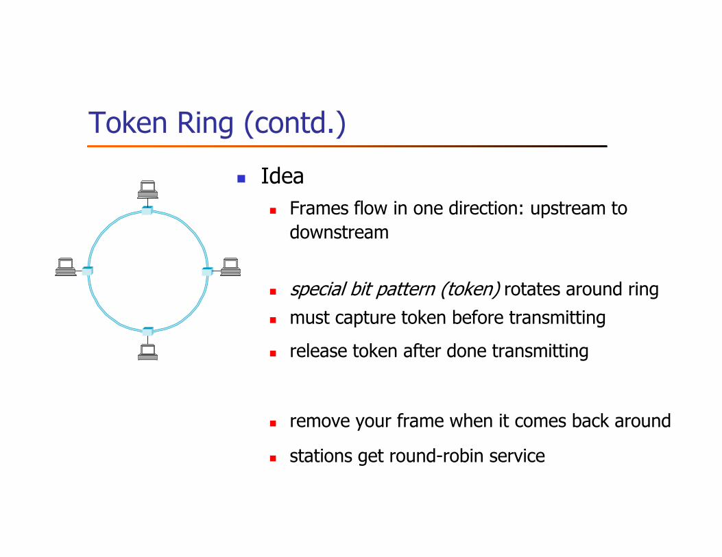
� Idea
� Frames flow in one direction: upstream to downstream
� special bit pattern (token) rotates around ring
� must capture token before transmitting
� release token after done transmitting
� remove your frame when it comes back around
� stations get round-robin service

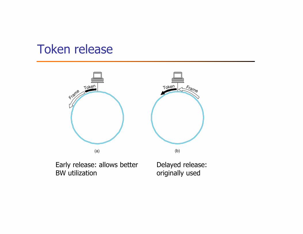
Token release
Token
Fram
eToken Frame
(a) (b)
Delayed release: originally used
Early release: allows better BW utilization
Token Ring: construct
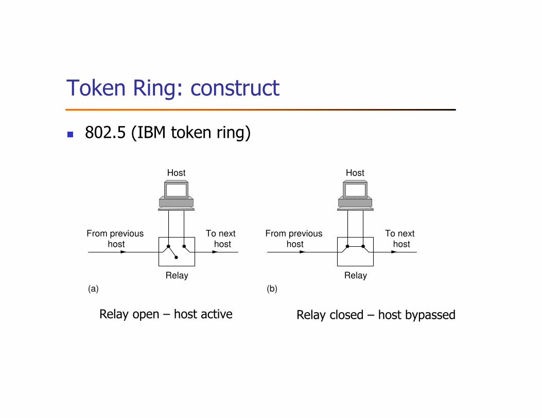
� 802.5 (IBM token ring)
Host
From previoushost
To nexthost
Relay
(a)
Host
Host Host
From previoushost
To nexthost
Relay
(b)
Relay open – host active Relay closed – host bypassed
Token Ring: construct (contd.)
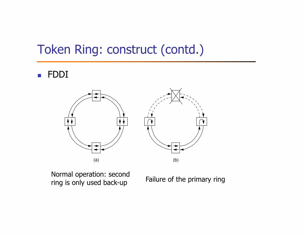
� FDDI
(a) (b)
Normal operation: second ring is only used back-up Failure of the primary ring
Token release
Token
Fram
eToken Frame
(a) (b)
Delayed release: originally used
Early release: allows better BW utilization
Our discussion here
focuses on FDDI, since 802.5 is pretty much a legacy
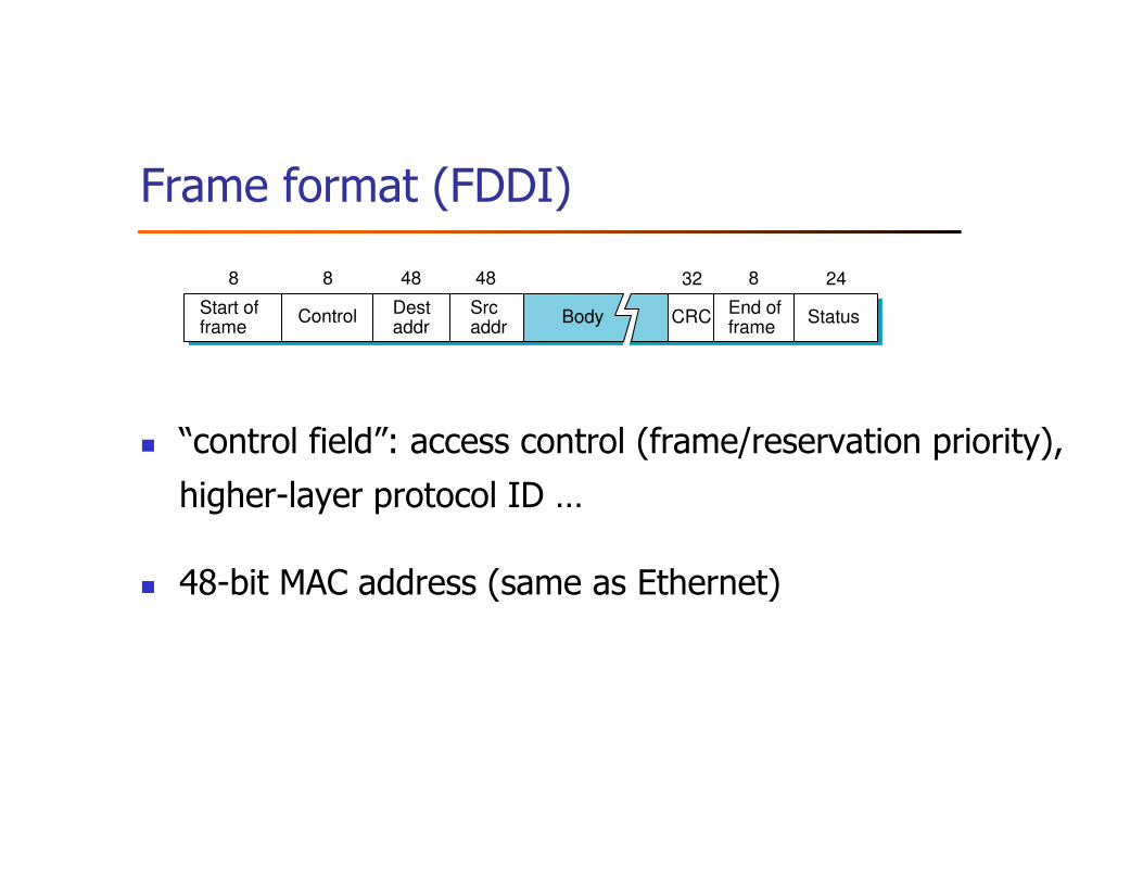
Frame format (FDDI)
� “control field”: access control (frame/reservation priority),
higher-layer protocol ID …
� 48-bit MAC address (same as Ethernet)
Control
8 8 8 24
CRCStart offrame
End offrame
Destaddr
Body
4848
Srcaddr
Status
32
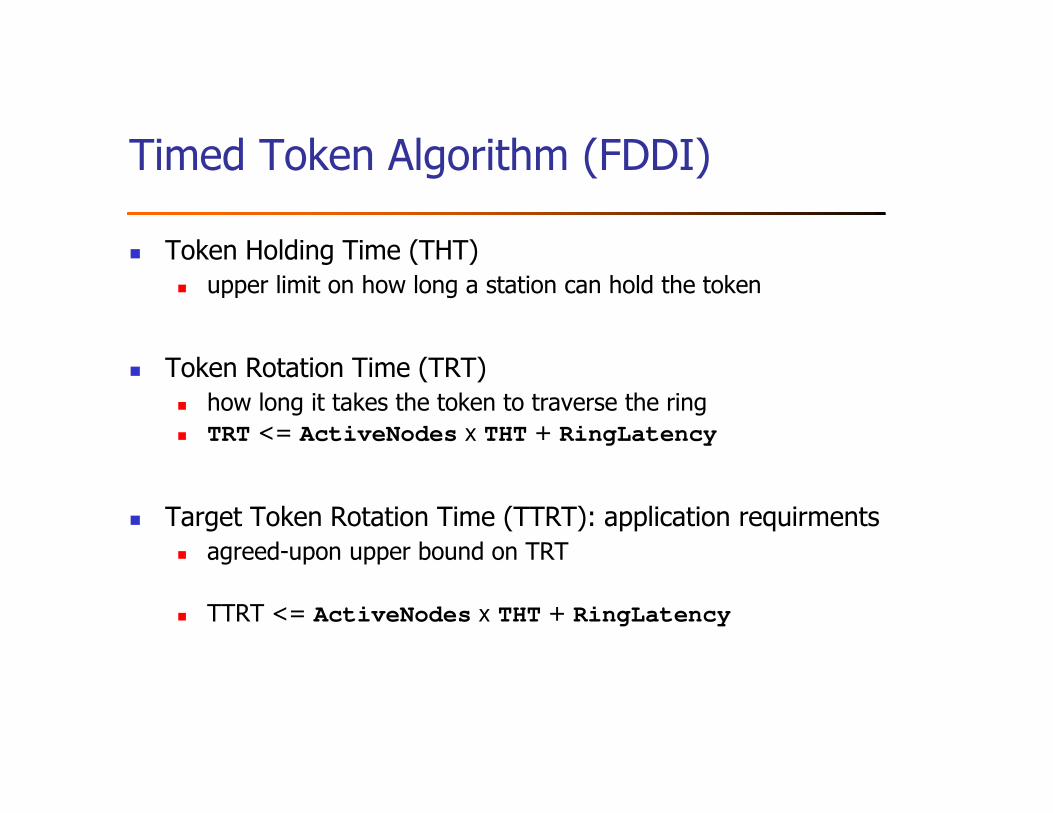
Timed Token Algorithm (FDDI)
� Token Holding Time (THT)� upper limit on how long a station can hold the token
� Token Rotation Time (TRT)� how long it takes the token to traverse the ring� TRT <= ActiveNodes x THT + RingLatency
� Target Token Rotation Time (TTRT): application requirments� agreed-upon upper bound on TRT
� TTRT <= ActiveNodes x THT + RingLatency
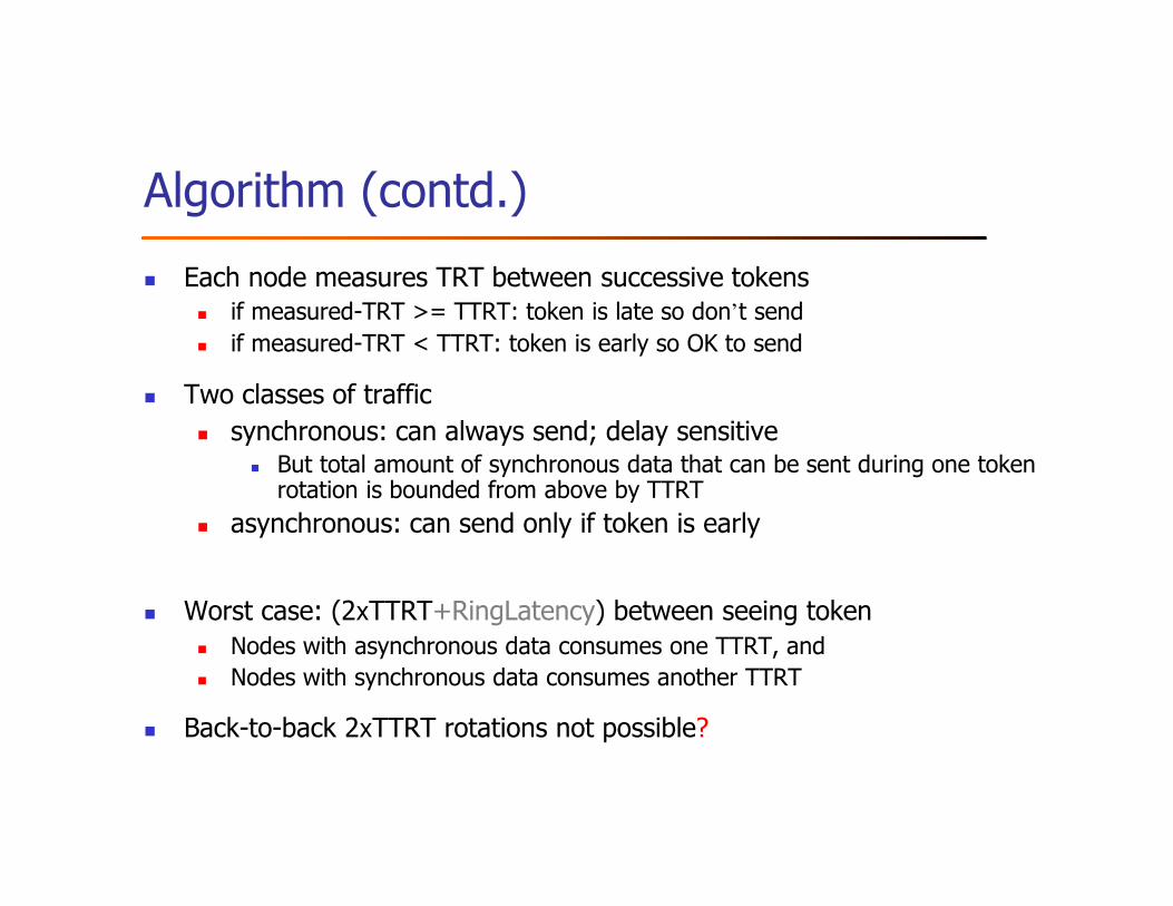
Algorithm (contd.)
� Each node measures TRT between successive tokens� if measured-TRT >= TTRT: token is late so don’t send� if measured-TRT < TTRT: token is early so OK to send
� Two classes of traffic
� synchronous: can always send; delay sensitive� But total amount of synchronous data that can be sent during one token rotation is bounded from above by TTRT
� asynchronous: can send only if token is early
� Worst case: (2xTTRT+RingLatency) between seeing token� Nodes with asynchronous data consumes one TTRT, and � Nodes with synchronous data consumes another TTRT
� Back-to-back 2xTTRT rotations not possible?
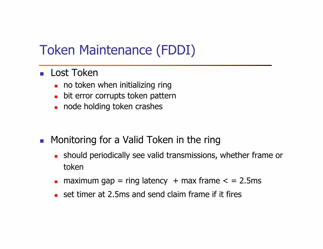
Token Maintenance (FDDI)
� Lost Token� no token when initializing ring� bit error corrupts token pattern� node holding token crashes
� Monitoring for a Valid Token in the ring
� should periodically see valid transmissions, whether frame or
token
� maximum gap = ring latency + max frame < = 2.5ms
� set timer at 2.5ms and send claim frame if it fires
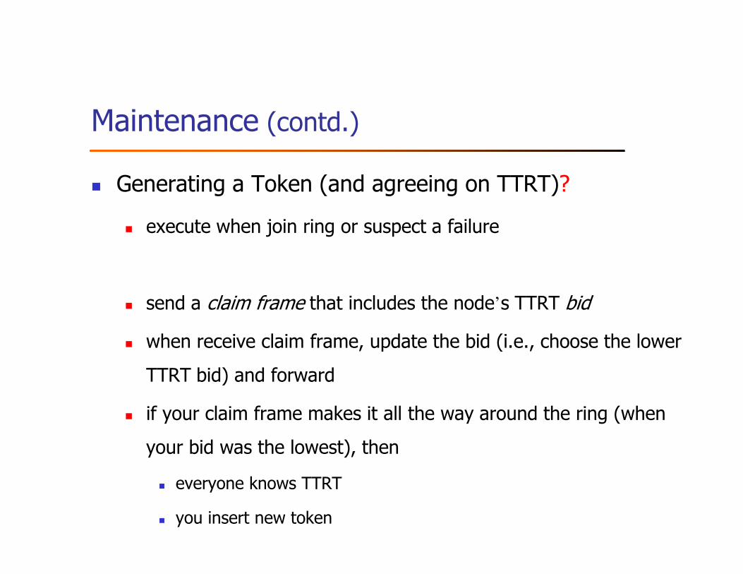
Maintenance (contd.)
� Generating a Token (and agreeing on TTRT)?
� execute when join ring or suspect a failure
� send a claim frame that includes the node’s TTRT bid
� when receive claim frame, update the bid (i.e., choose the lower
TTRT bid) and forward
� if your claim frame makes it all the way around the ring (when
your bid was the lowest), then
� everyone knows TTRT
� you insert new token
Outline
� Bus (Ethernet)
� Token ring (FDDI)
� Wireless (802.11)
� Discussion
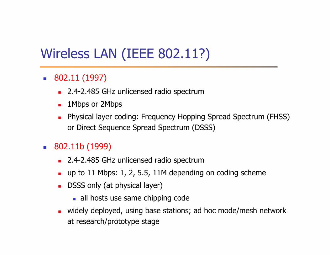
Wireless LAN (IEEE 802.11?)
� 802.11 (1997)
� 2.4-2.485 GHz unlicensed radio spectrum
� 1Mbps or 2Mbps
� Physical layer coding: Frequency Hopping Spread Spectrum (FHSS)
or Direct Sequence Spread Spectrum (DSSS)
� 802.11b (1999)
� 2.4-2.485 GHz unlicensed radio spectrum
� up to 11 Mbps: 1, 2, 5.5, 11M depending on coding scheme
� DSSS only (at physical layer)
� all hosts use same chipping code
� widely deployed, using base stations; ad hoc mode/mesh network
at research/prototype stage
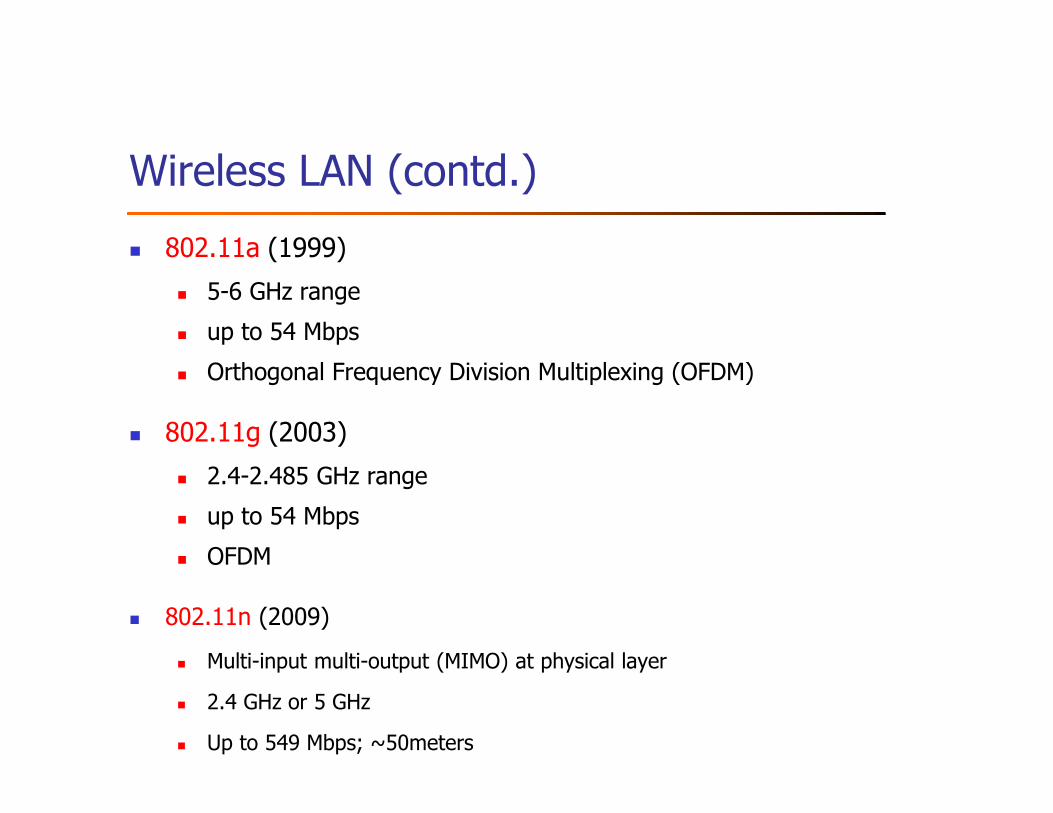
Wireless LAN (contd.)
� 802.11a (1999)
� 5-6 GHz range
� up to 54 Mbps
� Orthogonal Frequency Division Multiplexing (OFDM)
� 802.11g (2003)
� 2.4-2.485 GHz range
� up to 54 Mbps
� OFDM
� 802.11n (2009)
� Multi-input multi-output (MIMO) at physical layer
� 2.4 GHz or 5 GHz
� Up to 549 Mbps; ~50meters
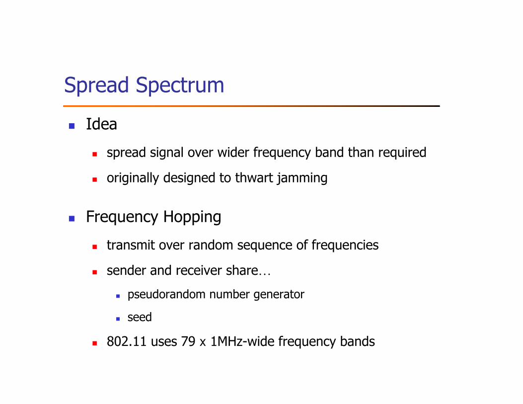
Spread Spectrum
� Idea
� spread signal over wider frequency band than required
� originally designed to thwart jamming
� Frequency Hopping
� transmit over random sequence of frequencies
� sender and receiver share…
� pseudorandom number generator
� seed
� 802.11 uses 79 x 1MHz-wide frequency bands
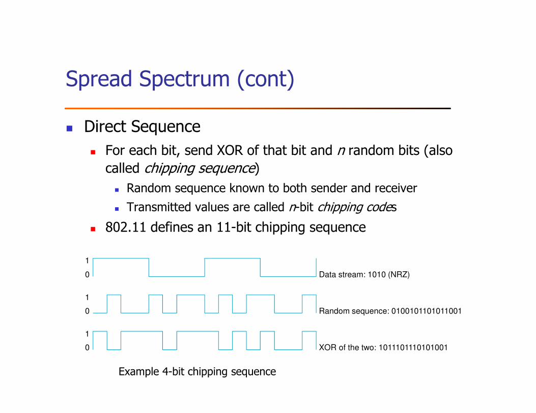
Spread Spectrum (cont)
� Direct Sequence
� For each bit, send XOR of that bit and n random bits (also called chipping sequence)
� Random sequence known to both sender and receiver
� Transmitted values are called n-bit chipping codes
� 802.11 defines an 11-bit chipping sequence
Example 4-bit chipping sequence
Random sequence: 0100101101011001
Data stream: 1010 (NRZ)
XOR of the two: 1011101110101001
0
0
0
1
1
1
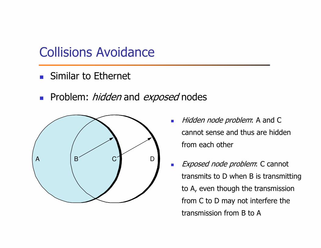
Collisions Avoidance
� Similar to Ethernet
� Problem: hidden and exposed nodes
A B C D
� Hidden node problem: A and C
cannot sense and thus are hidden
from each other
� Exposed node problem: C cannot
transmits to D when B is transmitting
to A, even though the transmission
from C to D may not interfere the
transmission from B to A
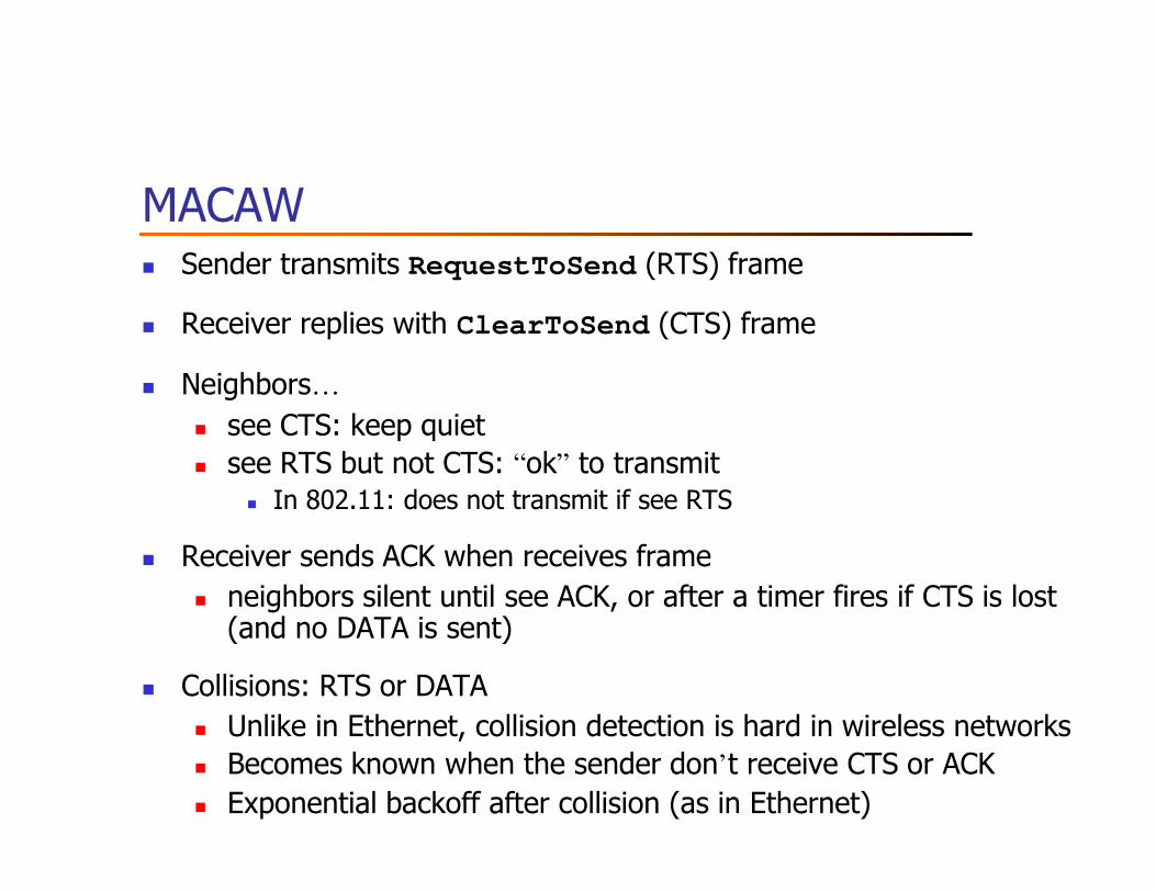
MACAW� Sender transmits RequestToSend (RTS) frame
� Receiver replies with ClearToSend (CTS) frame
� Neighbors…
� see CTS: keep quiet� see RTS but not CTS: “ok” to transmit
� In 802.11: does not transmit if see RTS
� Receiver sends ACK when receives frame
� neighbors silent until see ACK, or after a timer fires if CTS is lost (and no DATA is sent)
� Collisions: RTS or DATA
� Unlike in Ethernet, collision detection is hard in wireless networks� Becomes known when the sender don’t receive CTS or ACK� Exponential backoff after collision (as in Ethernet)
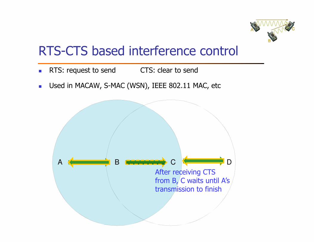
RTS-CTS based interference control
� RTS: request to send CTS: clear to send
� Used in MACAW, S-MAC (WSN), IEEE 802.11 MAC, etc
A B C D
After receiving CTS from B, C waits until A’s transmission to finish
Q: does MACAW eliminate hidden terminal problem?
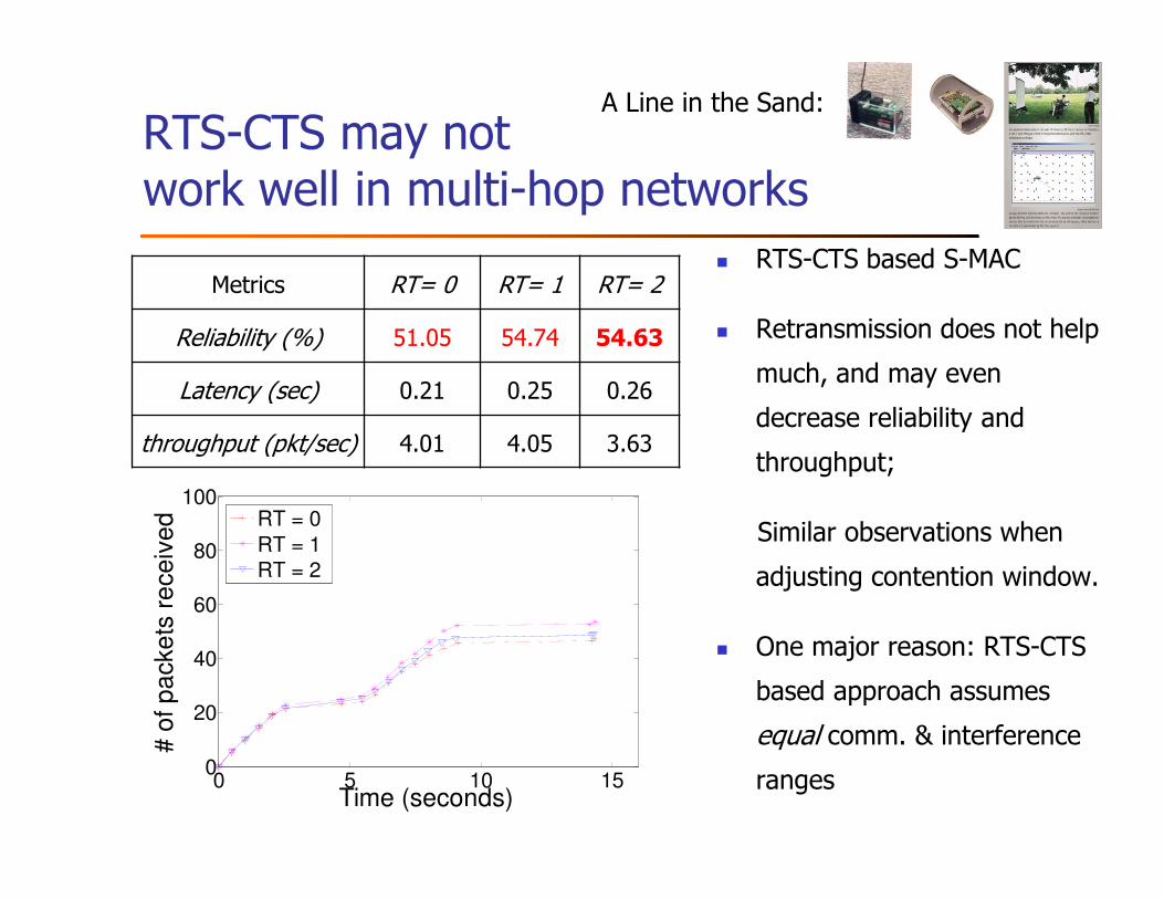
RTS-CTS may not work well in multi-hop networks
� RTS-CTS based S-MAC
� Retransmission does not help
much, and may even
decrease reliability and
throughput;
Similar observations when
adjusting contention window.
� One major reason: RTS-CTS
based approach assumes
equal comm. & interference
ranges
Metrics RT= 0 RT= 1 RT= 2
Reliability (%) 51.05 54.74 54.63
Latency (sec) 0.21 0.25 0.26
throughput (pkt/sec) 4.01 4.05 3.63
0 5 10 150
20
40
60
80
100
Time (seconds)
# o
f p
acke
ts r
ece
ive
d RT = 0
RT = 1
RT = 2
A Line in the Sand:
Wireless interference model: a basis for interference-oriented scheduling
� Predicts whether a set of concurrent transmissions may
interfere with one another
� Two commonly-used interference models
� Protocol model
� Physical model
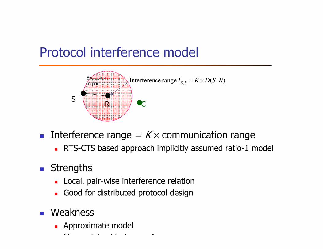
Protocol interference model
� Interference range = K × communication range� RTS-CTS based approach implicitly assumed ratio-1 model
� Strengths� Local, pair-wise interference relation
� Good for distributed protocol design
� Weakness� Approximate model
May well lead to low performance
SR C
),( range ceInterferen , RSDKI RS ×=Exclusionregion
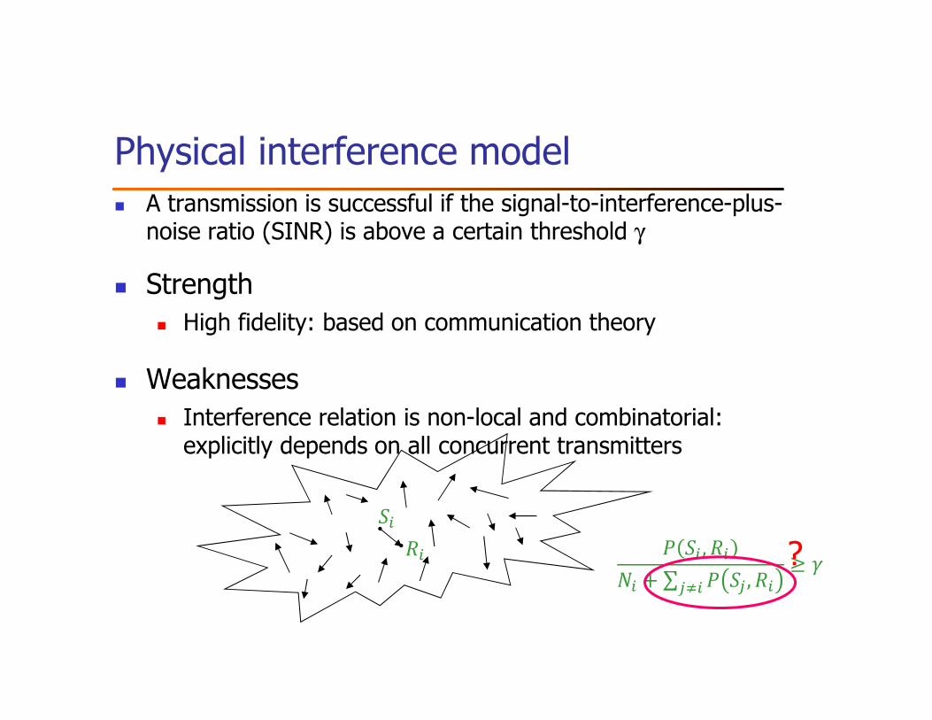
Physical interference model
� Strength� High fidelity: based on communication theory
� Weaknesses� Interference relation is non-local and combinatorial: explicitly depends on all concurrent transmitters
� A transmission is successful if the signal-to-interference-plus-noise ratio (SINR) is above a certain threshold γ
� �� , ��
�� + ∑ � � , ���
≥ �
��
�� ?
Open question
Interference model for predictable interference control:
locality of protocol model + high-fidelity of physical
model?
H. Zhang, X. Che, X. Liu, X. Ju, “Adaptive Instantiation of the Protocol Interference Model in
Wireless Networked Sensing and Control”, ACM Transactions on Sensor Networks, 10(2), 2014
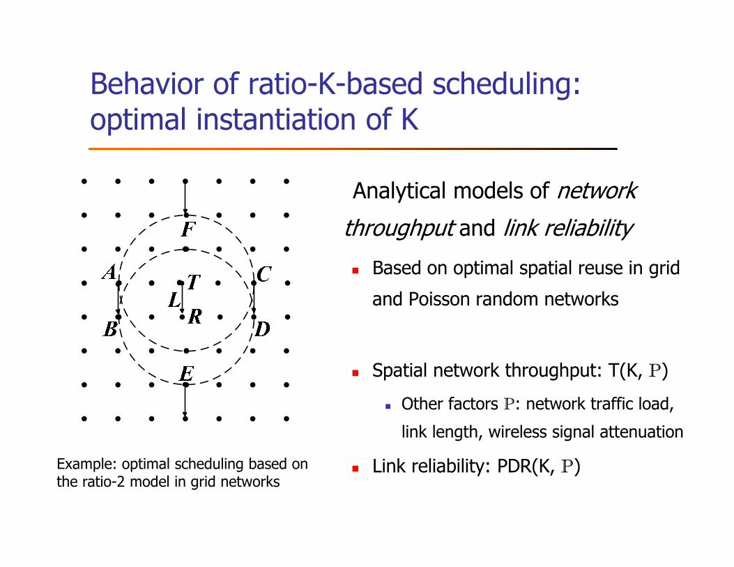
Behavior of ratio-K-based scheduling: optimal instantiation of K
Analytical models of network
throughput and link reliability
� Based on optimal spatial reuse in grid
and Poisson random networks
� Spatial network throughput: T(K, P)
� Other factors P: network traffic load,
link length, wireless signal attenuation
� Link reliability: PDR(K, P)Example: optimal scheduling based on the ratio-2 model in grid networks
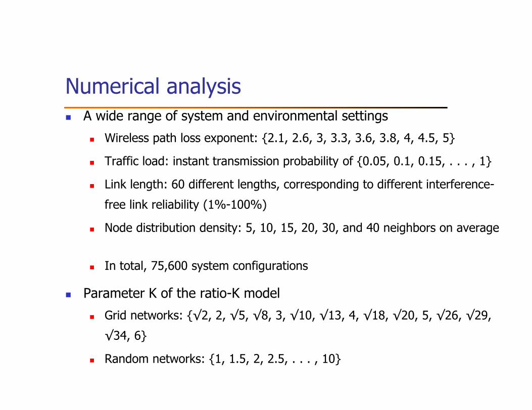
Numerical analysis � A wide range of system and environmental settings
� Wireless path loss exponent: {2.1, 2.6, 3, 3.3, 3.6, 3.8, 4, 4.5, 5}
� Traffic load: instant transmission probability of {0.05, 0.1, 0.15, . . . , 1}
� Link length: 60 different lengths, corresponding to different interference-
free link reliability (1%-100%)
� Node distribution density: 5, 10, 15, 20, 30, and 40 neighbors on average
� In total, 75,600 system configurations
� Parameter K of the ratio-K model
� Grid networks: {√2, 2, √5, √8, 3, √10, √13, 4, √18, √20, 5, √26, √29,
√34, 6}
� Random networks: {1, 1.5, 2, 2.5, . . . , 10}
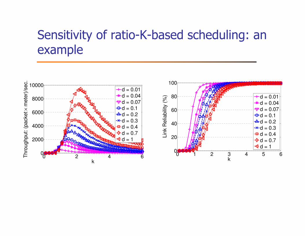
Sensitivity of ratio-K-based scheduling: an example
0 1 2 3 4 5 60
20
40
60
80
100
kLin
k R
elia
bili
ty (
%)
d = 0.01d = 0.04d = 0.07d = 0.1d = 0.2d = 0.3d = 0.4d = 0.7d = 1
0 2 4 60
2000
4000
6000
8000
10000
k
Thro
ughput: (
packet ×
mete
r)/s
ec.
d = 0.01d = 0.04
d = 0.07d = 0.1d = 0.2d = 0.3d = 0.4d = 0.7d = 1
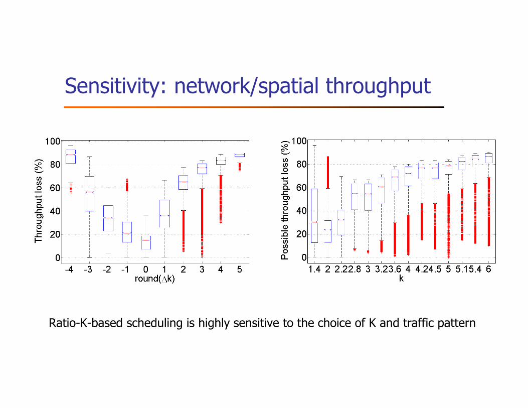
Sensitivity: network/spatial throughput
Ratio-K-based scheduling is highly sensitive to the choice of K and traffic pattern
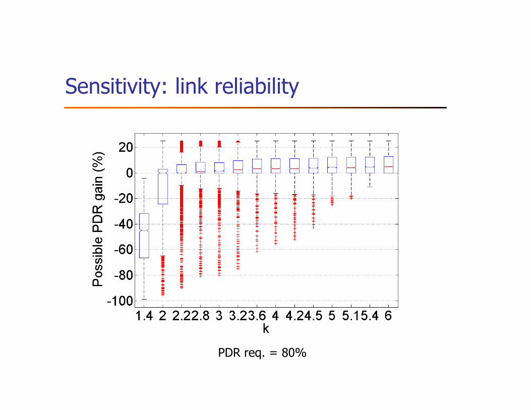
Sensitivity: link reliability
PDR req. = 80%
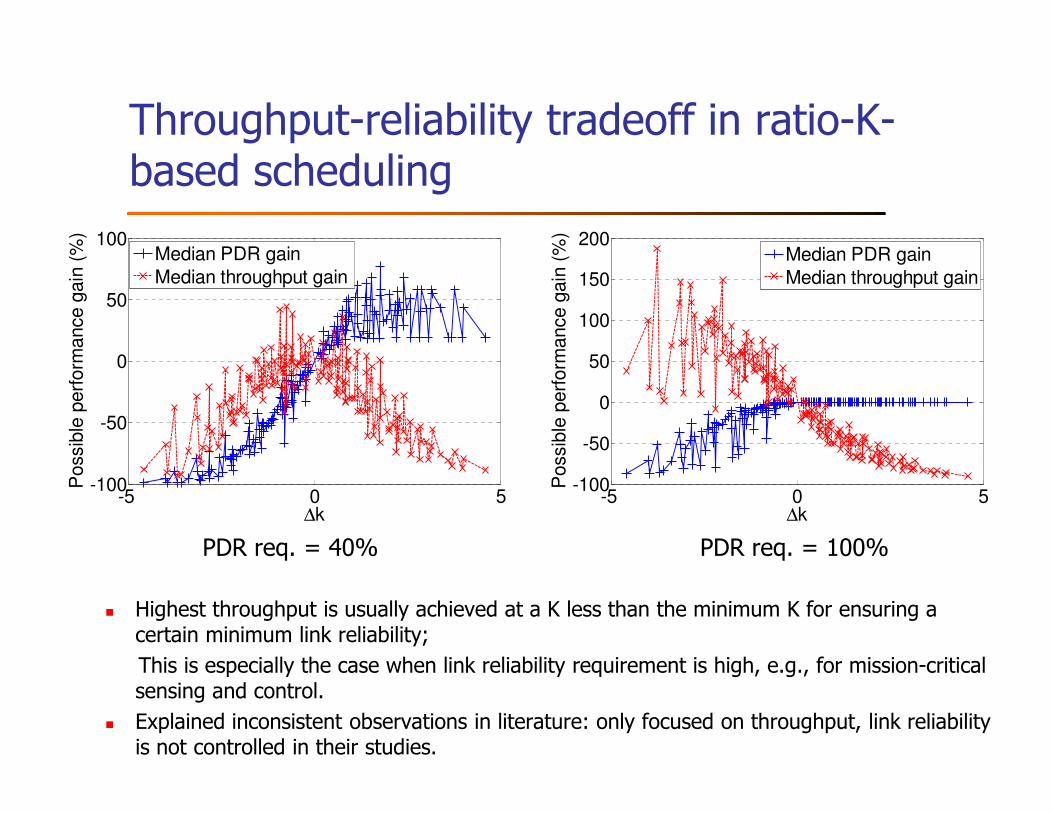
Throughput-reliability tradeoff in ratio-K-based scheduling
-5 0 5-100
-50
0
50
100
∆k
Possib
le p
erf
orm
ance g
ain
(%
)
Median PDR gain
Median throughput gain
-5 0 5-100
-50
0
50
100
150
200
∆k
Possib
le p
erf
orm
ance g
ain
(%
)
Median PDR gain
Median throughput gain
PDR req. = 40% PDR req. = 100%
� Highest throughput is usually achieved at a K less than the minimum K for ensuring a certain minimum link reliability;
This is especially the case when link reliability requirement is high, e.g., for mission-critical sensing and control.
� Explained inconsistent observations in literature: only focused on throughput, link reliability is not controlled in their studies.
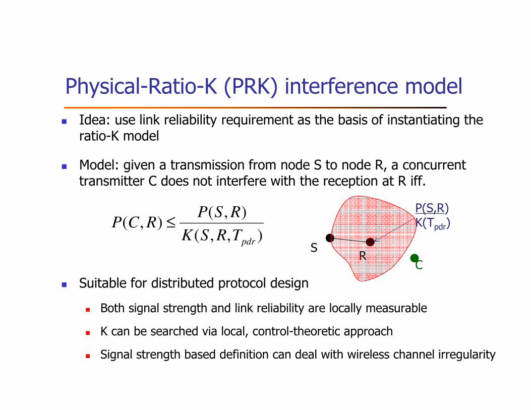
� Idea: use link reliability requirement as the basis of instantiating the ratio-K model
� Model: given a transmission from node S to node R, a concurrent transmitter C does not interfere with the reception at R iff.
� Suitable for distributed protocol design
� Both signal strength and link reliability are locally measurable
� K can be searched via local, control-theoretic approach
� Signal strength based definition can deal with wireless channel irregularity
Physical-Ratio-K (PRK) interference model
),,(
),(),(
pdrTRSK
RSPRCP ≤
P(S,R)K(Tpdr)
SR
C
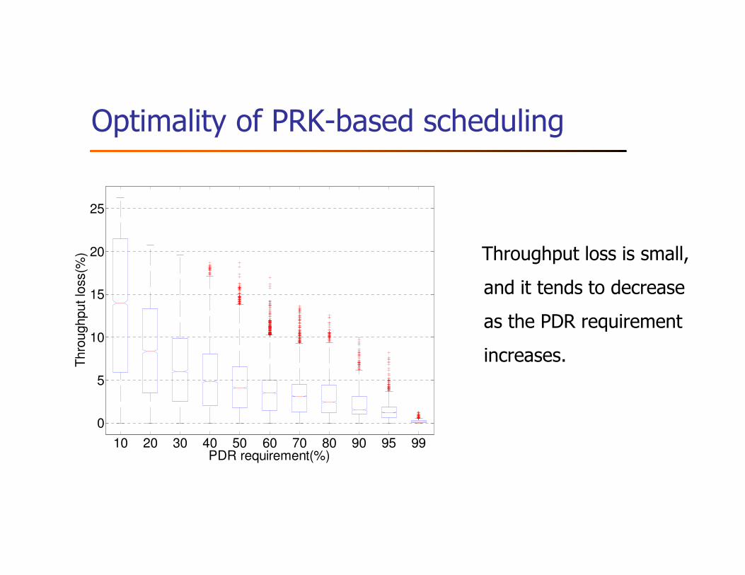
Optimality of PRK-based scheduling
10 20 30 40 50 60 70 80 90 95 99
0
5
10
15
20
25
Thro
ughput lo
ss(%
)
PDR requirement(%)
Throughput loss is small,
and it tends to decrease
as the PDR requirement
increases.
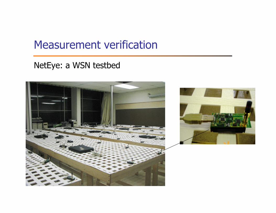
Measurement verification
NetEye: a WSN testbed
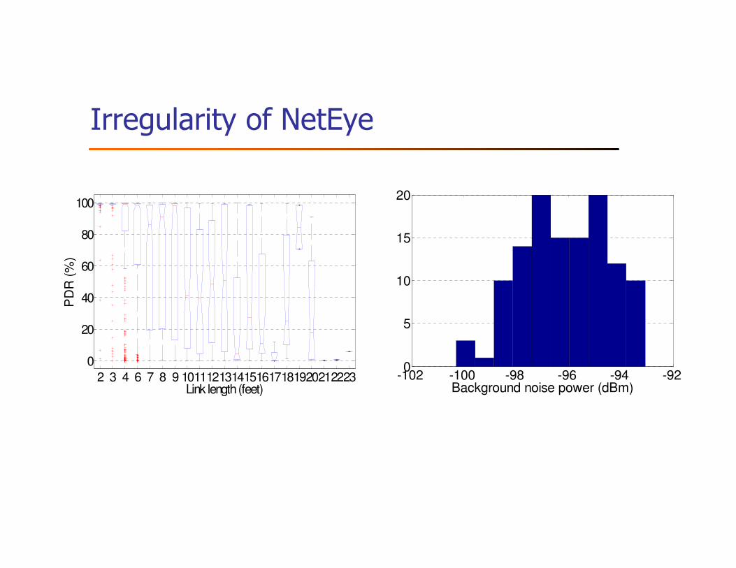
Irregularity of NetEye
2 3 4 6 7 8 9 1011121314151617181920212223
0
20
40
60
80
100
PD
R (
%)
Link length (feet)-102 -100 -98 -96 -94 -920
5
10
15
20
Background noise power (dBm)
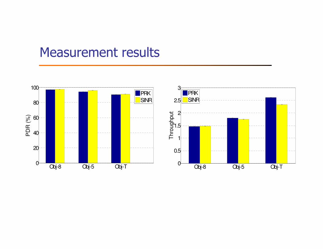
Measurement results
Obj-8 Obj-5 Obj-T0
20
40
60
80
100
PD
R (
%)
PRK
SINR
Obj-8 Obj-5 Obj-T0
0.5
1
1.5
2
2.5
3
Thro
ughput
PRK
SINR
Physical Ratio-K (PRK) interference model
� Enables local protocols (e.g., localized, online search of K)
� Locality implies responsive adaptation (to dynamics in traffic
pattern etc)
� Enables measurement-based (instead of model-based) online
adaptation
� No need for precise PDR-SINR models
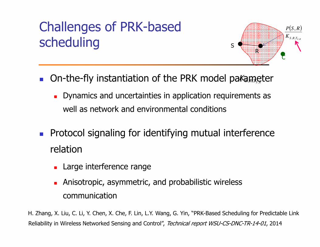
Challenges of PRK-based scheduling
� On-the-fly instantiation of the PRK model parameter
� Dynamics and uncertainties in application requirements as
well as network and environmental conditions
� Protocol signaling for identifying mutual interference
relation
� Large interference range
� Anisotropic, asymmetric, and probabilistic wireless
communication
RSTRSK,,,
H. Zhang, X. Liu, C. Li, Y. Chen, X. Che, F. Lin, L.Y. Wang, G. Yin, “PRK-Based Scheduling for Predictable Link
Reliability in Wireless Networked Sensing and Control”, Technical report WSU-CS-DNC-TR-14-01, 2014
SR
C
( )
RSTRSK
RSP
,,,
,
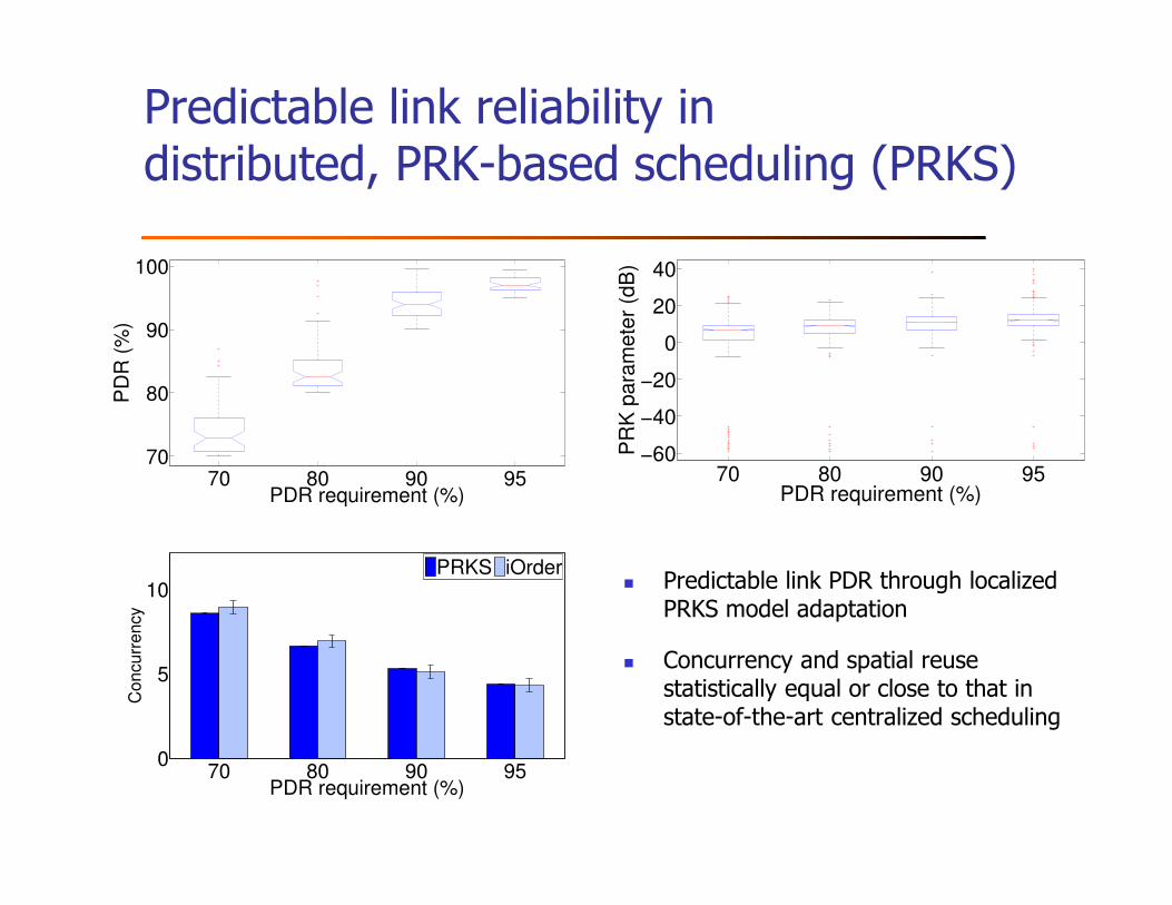
Predictable link reliability in distributed, PRK-based scheduling (PRKS)
� Predictable link PDR through localized PRKS model adaptation
� Concurrency and spatial reuse statistically equal or close to that in state-of-the-art centralized scheduling
70 80 90 95−60
−40
−20
0
20
40
PDR requirement (%)
PR
K p
ara
me
ter
(dB
)
70 80 90 9570
80
90
100
PD
R (
%)
PDR requirement (%)
70 80 90 950
5
10
PDR requirement (%)
Concurr
ency
PRKS iOrder
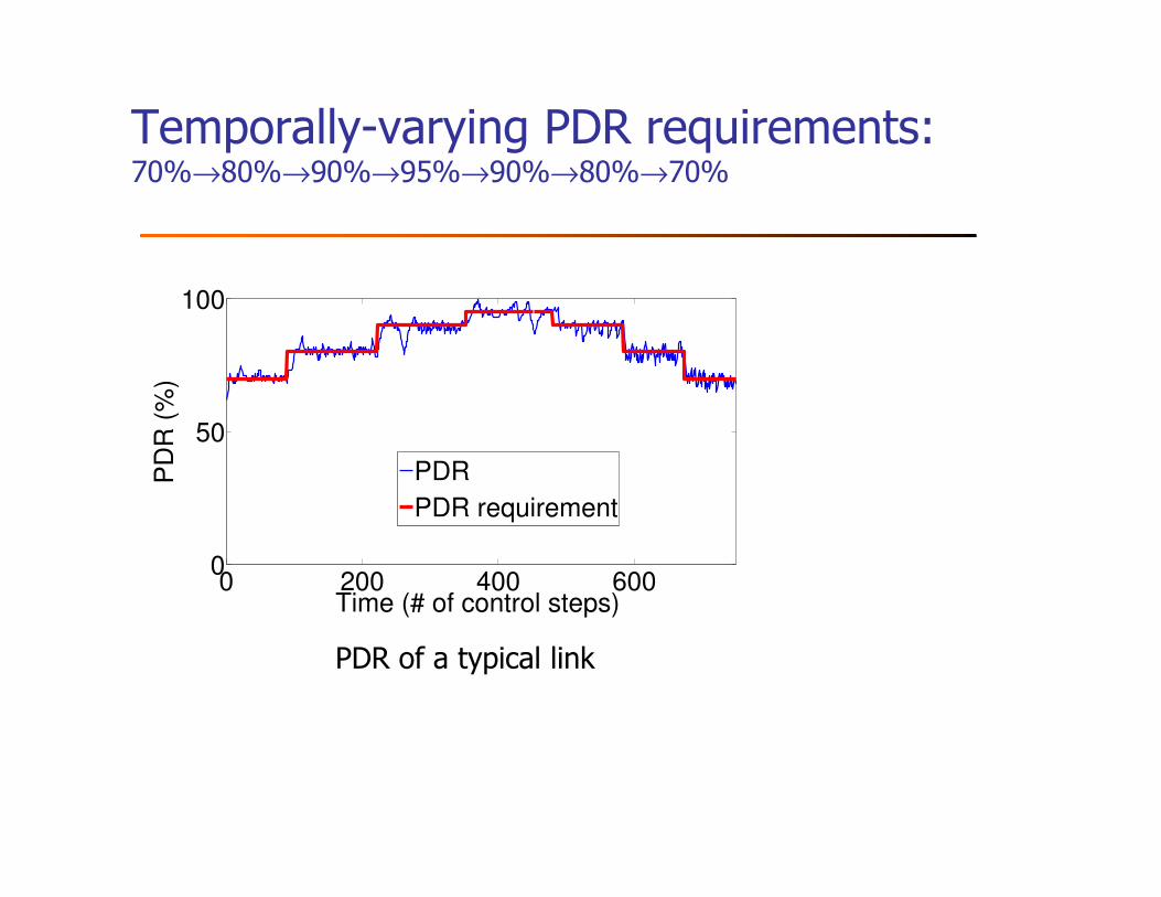
Temporally-varying PDR requirements:70%→80%→90%→95%→90%→80%→70%
0 200 400 6000
50
100
Time (# of control steps)
PD
R (
%)
PDR
PDR requirement
PDR of a typical link
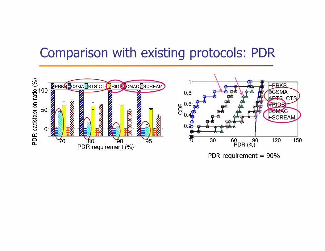
Comparison with existing protocols: PDR
0 30 60 90 120 1500
0.2
0.4
0.6
0.8
1
PDR (%)
CD
F
PRKSCSMARTS−CTSRIDBCMACSCREAM
PDR requirement = 90%
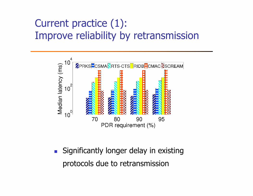
Current practice (1): Improve reliability by retransmission
� Significantly longer delay in existing
protocols due to retransmission
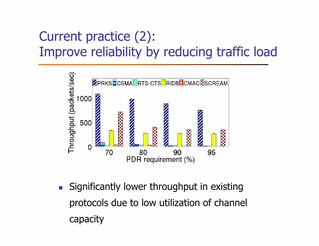
Current practice (2): Improve reliability by reducing traffic load
� Significantly lower throughput in existing
protocols due to low utilization of channel
capacity
Summary: PRK-based scheduling (PRKS)
� PRKS as a field-deployable approach to the 40+ years old
problem of predictable co-channel interference control
� Control-theoretic approach to PRK model instantiation
� Signal maps as basis of protocol signaling
� Two-timescale approach to TDMA
� Predictable reliability as a basis for controllable reliability-
delay-throughput tradeoff and thus co-design of control and
networking
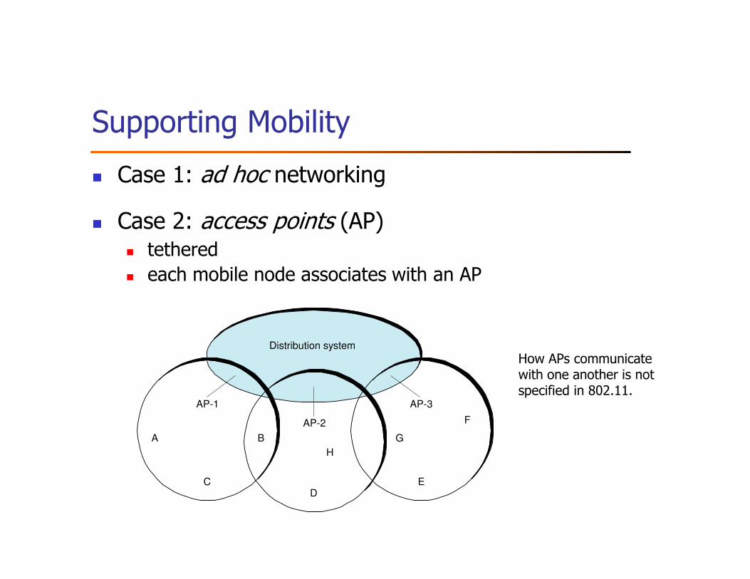
Supporting Mobility
� Case 1: ad hoc networking
� Case 2: access points (AP)� tethered� each mobile node associates with an AP
B
H
A
F
G
D
AP-2
AP-3AP-1
C E
Distribution system
How APs communicate with one another is not specified in 802.11.
Mobility (contd.)
� Active scanning (selecting an AP): when join or move
� node sends Probe frame
� all AP’s w/in reach reply with ProbeResponse frame
� node selects one AP; sends it AssociateRequest frame
� AP replies with AssociationResponse frame
� new AP informs old AP via tethered network
� Passive scanning: AP periodically sends Beacon frame
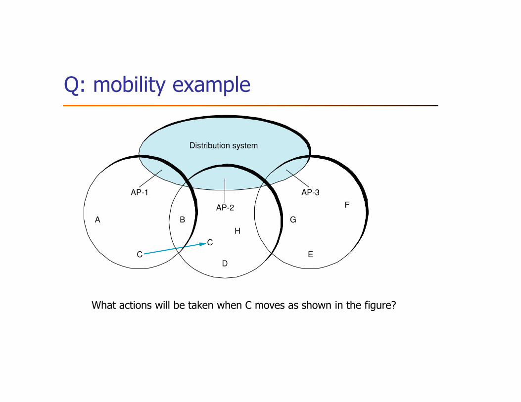
Q: mobility example
B
H
A
F
G
D
AP-2
AP-3AP-1
EC
C
Distribution system
What actions will be taken when C moves as shown in the figure?
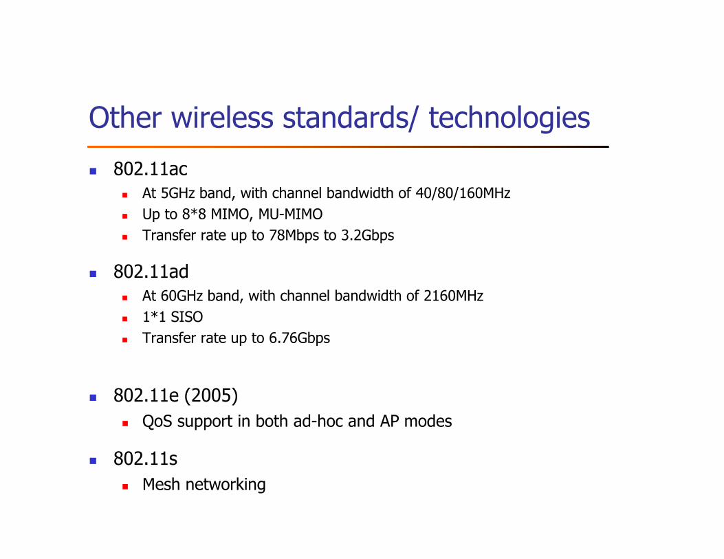
Other wireless standards/ technologies
� 802.11ac� At 5GHz band, with channel bandwidth of 40/80/160MHz
� Up to 8*8 MIMO, MU-MIMO
� Transfer rate up to 78Mbps to 3.2Gbps
� 802.11ad� At 60GHz band, with channel bandwidth of 2160MHz
� 1*1 SISO
� Transfer rate up to 6.76Gbps
� 802.11e (2005)
� QoS support in both ad-hoc and AP modes
� 802.11s
� Mesh networking
Other wireless standards (contd.)
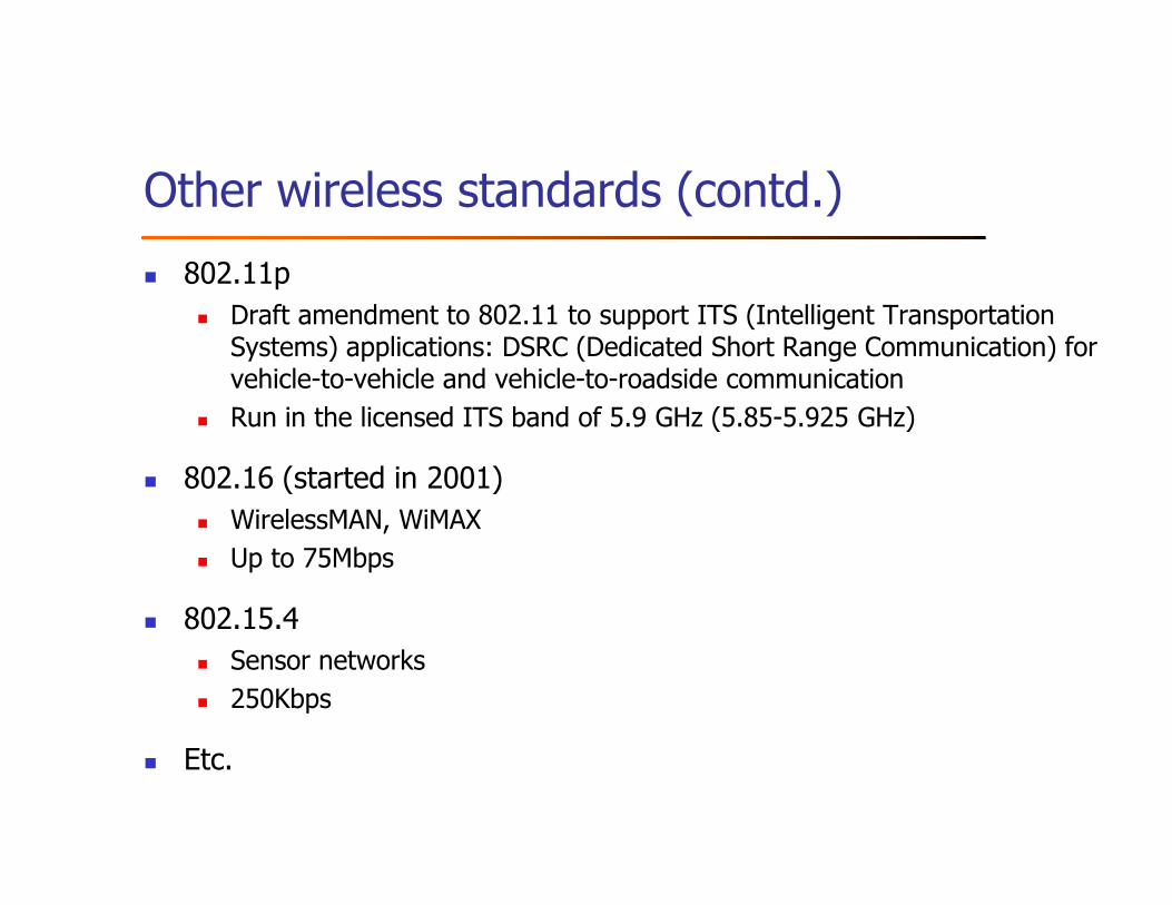
� 802.11p
� Draft amendment to 802.11 to support ITS (Intelligent Transportation Systems) applications: DSRC (Dedicated Short Range Communication) for vehicle-to-vehicle and vehicle-to-roadside communication
� Run in the licensed ITS band of 5.9 GHz (5.85-5.925 GHz)
� 802.16 (started in 2001)
� WirelessMAN, WiMAX
� Up to 75Mbps
� 802.15.4
� Sensor networks
� 250Kbps
� Etc.
Outline
� Bus (Ethernet)
� Token ring (FDDI)
� Wireless (802.11)
� Discussion
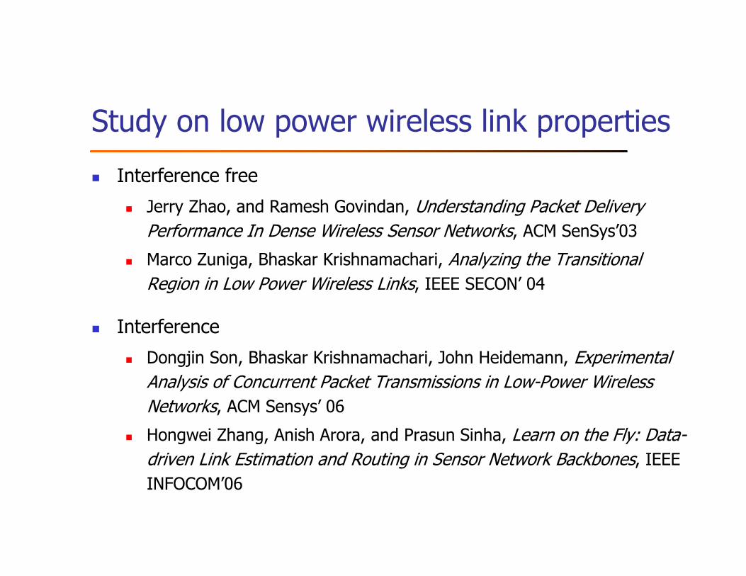
Study on low power wireless link properties
� Interference free
� Jerry Zhao, and Ramesh Govindan, Understanding Packet Delivery
Performance In Dense Wireless Sensor Networks, ACM SenSys’03
� Marco Zuniga, Bhaskar Krishnamachari, Analyzing the Transitional
Region in Low Power Wireless Links, IEEE SECON’ 04
� Interference
� Dongjin Son, Bhaskar Krishnamachari, John Heidemann, Experimental
Analysis of Concurrent Packet Transmissions in Low-Power Wireless
Networks, ACM Sensys’ 06
� Hongwei Zhang, Anish Arora, and Prasun Sinha, Learn on the Fly: Data-
driven Link Estimation and Routing in Sensor Network Backbones, IEEE
INFOCOM’06
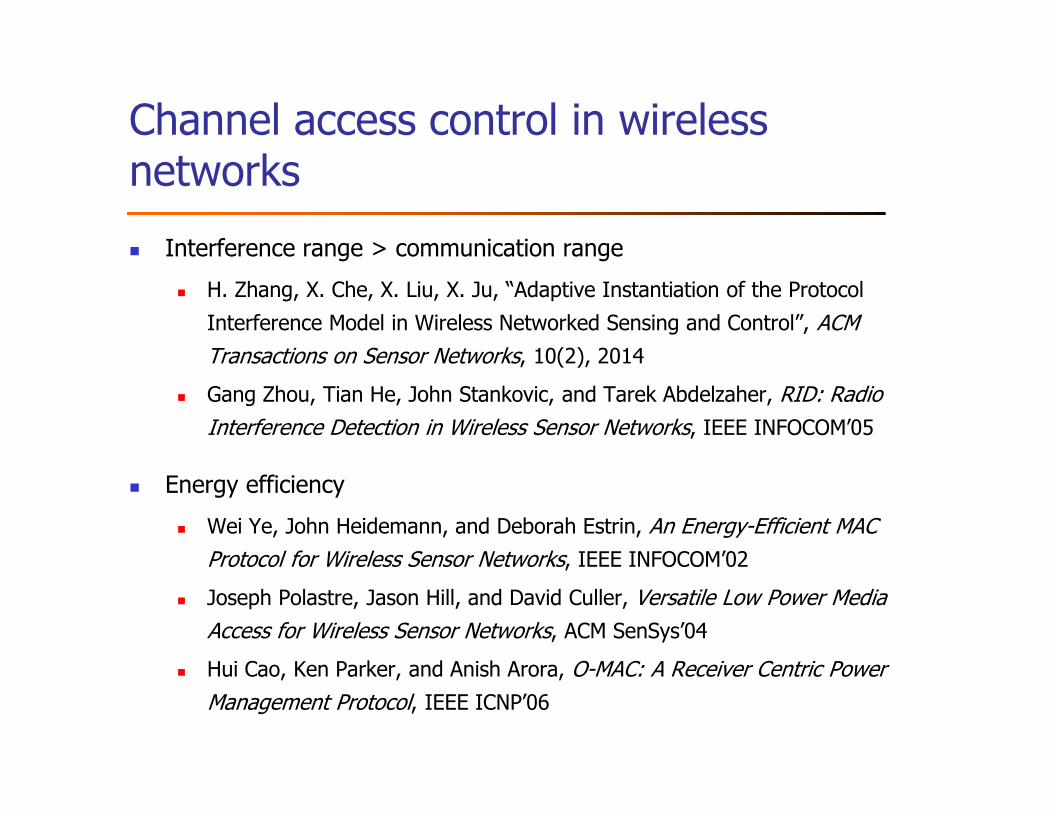
Channel access control in wireless networks
� Interference range > communication range
� H. Zhang, X. Che, X. Liu, X. Ju, “Adaptive Instantiation of the Protocol
Interference Model in Wireless Networked Sensing and Control”, ACM
Transactions on Sensor Networks, 10(2), 2014
� Gang Zhou, Tian He, John Stankovic, and Tarek Abdelzaher, RID: Radio
Interference Detection in Wireless Sensor Networks, IEEE INFOCOM’05
� Energy efficiency
� Wei Ye, John Heidemann, and Deborah Estrin, An Energy-Efficient MAC
Protocol for Wireless Sensor Networks, IEEE INFOCOM’02
� Joseph Polastre, Jason Hill, and David Culler, Versatile Low Power Media
Access for Wireless Sensor Networks, ACM SenSys’04
� Hui Cao, Ken Parker, and Anish Arora, O-MAC: A Receiver Centric Power
Management Protocol, IEEE ICNP’06
Further reading
� Ethernet
� R. Metcalf and D. Boggs, Ethernet: Distributed Packet Switching for
Local Computer Networks, Communications of ACM, 19(7):395-403,
July 1976
� D. Boggs, J. Mogul, and C. Kent, Measured Capacity of an Ethernet,
ACM SIGCOMM’88
� Integrating high-speed network adaptors with system software
� P. Druschel, M. Abbot, M. Pagels, and L.L. Peterson, Network
Subsystem Design, IEEE Networks, 7(4):8-17, July 1993
Summary
� Point-to-point links
� Encoding
� Framing
� Error detection
� Reliable transmission
� Shared access networks
� Channel access control
TinyOS: wireless communication
� Example app: BlinkToRadio
� tinyos-2.x\apps\tutorials\BlinkToRadio
Assignment – Chapter 2
� TinyLab#1 (optional)
� Write a TinyOS program that let a sender continuously transmit packets (with increasing packet sequence number) to a receiver; run the program using TOSSIM
� Implement the sliding window algorithm in TinyOS, and test it using TOSSIM
� Exercise#1
� Exercises 1, 5, 26, and 33
� Exercise 42� Hint: 1) the relation between propagation delay, transmission rate, and minimum packet size in CSMA/CD networks; 2) too large a minimum packet size may require padding and thus bandwidth wastage
� TinyExam#1