Shaping nanoscale magnetic domain memory in exchange ...
8
ARTICLE Received 7 Nov 2015 | Accepted 18 Apr 2016 | Published 1 Jun 2016 Shaping nanoscale magnetic domain memory in exchange-coupled ferromagnets by field cooling Karine Chesnel 1 , Alex Safsten 1 , Matthew Rytting 1 & Eric E. Fullerton 2 The advance of magnetic nanotechnologies relies on detailed understanding of nanoscale magnetic mechanisms in materials. Magnetic domain memory (MDM), that is, the tendency for magnetic domains to repeat the same pattern during field cycling, is important for magnetic recording technologies. Here we demonstrate MDM in [Co/Pd]/IrMn films, using coherent X-ray scattering. Under illumination, the magnetic domains in [Co/Pd] produce a speckle pattern, a unique fingerprint of their nanoscale configuration. We measure MDM by cross-correlating speckle patterns throughout magnetization processes. When cooled below its blocking temperature, the film exhibits up to 100% MDM, induced by exchange-coupling with the underlying IrMn layer. The degree of MDM drastically depends on cooling conditions. If the film is cooled under moderate fields, MDM is high throughout the entire magnetization loop. If the film is cooled under nearly saturating field, MDM vanishes, except at nucleation and saturation. Our findings show how to fully control the occurrence of MDM by field cooling. DOI: 10.1038/ncomms11648 OPEN 1 Department of Physics and Astronomy, Brigham Young University, Provo, Utah 84602, USA. 2 Center for Memory and Recording Research, University of California San Diego, La Jolla, California 92093-0401, USA. Correspondence and requests for materials should be addressed to K.C. (email: [email protected]). NATURE COMMUNICATIONS | 7:11648 | DOI: 10.1038/ncomms11648 | www.nature.com/naturecommunications 1
Transcript of Shaping nanoscale magnetic domain memory in exchange ...

ARTICLE
Received 7 Nov 2015 | Accepted 18 Apr 2016 | Published 1 Jun 2016
Shaping nanoscale magnetic domain memory inexchange-coupled ferromagnets by field coolingKarine Chesnel1, Alex Safsten1, Matthew Rytting1 & Eric E. Fullerton2
The advance of magnetic nanotechnologies relies on detailed understanding of nanoscale
magnetic mechanisms in materials. Magnetic domain memory (MDM), that is, the tendency
for magnetic domains to repeat the same pattern during field cycling, is important for
magnetic recording technologies. Here we demonstrate MDM in [Co/Pd]/IrMn films, using
coherent X-ray scattering. Under illumination, the magnetic domains in [Co/Pd] produce a
speckle pattern, a unique fingerprint of their nanoscale configuration. We measure MDM by
cross-correlating speckle patterns throughout magnetization processes. When cooled below
its blocking temperature, the film exhibits up to 100% MDM, induced by exchange-coupling
with the underlying IrMn layer. The degree of MDM drastically depends on cooling
conditions. If the film is cooled under moderate fields, MDM is high throughout the entire
magnetization loop. If the film is cooled under nearly saturating field, MDM vanishes, except
at nucleation and saturation. Our findings show how to fully control the occurrence of MDM
by field cooling.
DOI: 10.1038/ncomms11648 OPEN
1 Department of Physics and Astronomy, Brigham Young University, Provo, Utah 84602, USA. 2 Center for Memory and Recording Research, University ofCalifornia San Diego, La Jolla, California 92093-0401, USA. Correspondence and requests for materials should be addressed to K.C.(email: [email protected]).
NATURE COMMUNICATIONS | 7:11648 | DOI: 10.1038/ncomms11648 | www.nature.com/naturecommunications 1

Understanding the mechanisms driving nanoscalemagnetic reversal and memory phenomena in layeredmagnetic films is essential for the development of
magnetic recording and spintronic nanotechnologies1–4. Thinferromagnetic (F) films with perpendicular magnetic anisotropy(PMA) are used for high-density magnetic recording applicationsbecause they allow the control of nanometric magnetic domainsto encode information5–9. Interlaying PMA films with other F,antiferromagnetic (AF) or non-magnetic layers in nano-patternedcomposite structures has enabled the development of magneticmemory devices10–12. The layering of PMA films, especiallyexchange-coupling F layers with AF layers, leads to specificmagnetic domain topologies and associated memory properties.These mechanisms are however very complex and still requiremore detailed understanding.
Although studies of PMA media are generally based onmacroscopic magnetometry observations13,14, a microscopic viewof the magnetic properties, which can be obtained via magneticmicroscopy15–18 and X-ray scattering19–22, is often lacking.We present here a unique coherent X-ray magnetic correlationstudy, mapping out nanoscale magnetic memory phenomenain exchange-biased PMA multilayers throughout theirmagnetization process. We show how magnetic domainmemory (MDM), that is, the ability for the magnetic domainpattern in an F layer to retrieve its exact same domaintopology after field cycling, can be turned on or off andspatially controlled by tuning the nature of the exchange biaswith an AF template.
Single PMA F films alone do not normally exhibit MDM. If thefilm is relatively smooth, magnetic domains nucleate andpropagate randomly throughout the material when an externalmagnetic field is cycled. Even though the net magnetization of thefilm is uniquely defined at a given applied field and following agiven magnetization history, the nanoscale domain pattern isusually not uniquely defined. Although the average domain sizeremains the same, an unlimited number of different domainpatterns can lead to the same net magnetic moment. Each timethe F film is saturated and magnetization is cycled, thedomain pattern evolves through a new domain configuration.Consequently, the films show little or no MDM when the externalmagnetic field is cycled.
If the film is somewhat rough, some MDM may occur, inducedby defects23. In this instance, the observed defect-inducedmemory is only partial (between 10 and 50%) and is highest inthe nucleation phase of the magnetization process24. The defectstend to pin the nucleating sites for the magnetic domains, but thedomain propagation remains mostly random, thus leading to aloss of MDM during the rest of the magnetization process.
Here we show how up to 100% MDM can be achieved, even invery smooth F films, by exploiting exchange coupling with an AFtemplate. MDM can be turned on by cooling the film below theblocking temperature TB and it can be turned off again by heatingabove TB. Moreover, we show how the spatial occurrence ofMDM at the nanoscale can be shaped throughout themagnetization process by finely adjusting the amount of netexchange bias, that is, the magnitude of the applied field whilecooling. Our preliminary studies revealing the occurrence of highMDM induced by exchange coupling25, its spatial dependency26
and temperature dependency27 were limited to the specific case ofzero-field cooling (ZFC). In the present study, we show acomplete mapping of MDM that investigates a whole range offield-cooling (FC) conditions, thus revealing surprisingbehaviours when the cooling field is pushed towards saturation.These results show that nanoscale spatial dependence of domainmemory can be controlled by varying the amount of exchangebias imprinted in the material.
ResultsMacroscopic magnetic properties. Our PMA F films are basedon well-studied [Co/Pd] multilayers8,13 that exhibits serpentine-shaped magnetic domains that are B150–200 nm in width. In theabsence of external magnetic field, these domains usually form ananoscale labyrinthine pattern, as seen on Fig. 1a. To incorporatemagnetic exchange coupling into the films28, the [Co/Pd] F layersare periodically interlayed with thin AF layers made of an IrMnalloy, thus forming a [[Co(4 Å)/Pd(7Å)]� 12/IrMn(24 Å)]� 4
multilayer. Dipolar fields correlate the domains in adjacent Flayers and exchange coupling occurs between the F and AF layerswhen the film is cooled below a blocking temperature TBB300 K.FC this film below TB induces significant modifications in themagnetization loop, enhancing the coercive field and inducing anet bias (shifting of the loop), as shown in Fig. 1b. At 20 K, theobserved net bias is B200 Oe, in the direction opposite tothe field applied during the cooling (here þ 10 kOe). The loop iswidened by B300 Oe at its narrowest region (coercive point) andby B600 Oe at its widest region (gap between saturation andnucleation points increasing from 2,400 Oe at 300 K to 3,000 Oeat 20 K). As in ZFC conditions25, the widening of the loop resultsfrom exchange couplings between the Co spins in the F layer withthe interfacial uncompensated Mn spins in the IrMn AF layer.The biasing of the loop is caused by the net magnetic momentimprinted in the IrMn after FC. These magnetizationmeasurements give macroscopic information about the film’snet magnetization M only. To probe the associated magneticdomains at the nanoscale and its evolution throughout themagnetization process at low temperature, we use soft X-rayscattering. With a wavelength in the nanometric range, softX-rays provide a perfect tool to resolve nano-sized magneticdomains and their spatial topological changes under theapplication of an in-situ magnetic field.
X-ray magnetic scattering patterns. The [Co/Pd]/IrMn magneticfilms were studied via coherent X-ray resonant magneticscattering (CXRMS)29 using synchrotron radiation. In thisCXRMS experiments, the films were exposed to coherent X-raylight and produced scattering patterns detected downstream, asshown in Fig. 1c. The films were mounted on a cryogenic holderto allow the cooling of samples down to B20 K with liquidhelium. An in-situ magnetic field was applied perpendicular tothe films via sets of conically shaped octupolar electromagnets30.After being demagnetized at high temperature, around 400 K, thefilms were cooled down to 20 K under a given external magneticfield HFC. The experiment was repeated in various FC conditions.The magnitude of the cooling field HFC varied from zero (ZFC)up to 3,200 Oe, which is near the saturation point. In each FCstate, once the temperature had stabilized near 20 K, the magneticfield was cycled and CXRMS speckle patterns were collectedthroughout the magnetization process.
When illuminated by coherent X-rays tuned to magneticresonance energies, the magnetic domains in the film scatter thelight and produce a magnetic scattering pattern that is speckled.As the film is relatively smooth and fully dense31, it does notproduce any significant charge scattering signal and the observedsignal is essentially magnetic, as illustrated by the selection ofas-collected scattering images in Fig. 1d–f. At nucleation (Fig. 1d),the sparse nucleated domains produce a faint disk-like scatteringsignal; in the coercive region (Fig. 1e), the fully propagatedmagnetic domains produce a bright ring-like scattering pattern; atsaturation (Fig. 1f), domains have disappeared and the scatteringsignal vanishes, thus confirming that the observed scatteringsignal is essentially magnetic. To ensure that we only retain themagnetic signal in our analysis, we subtract the saturation
ARTICLE NATURE COMMUNICATIONS | DOI: 10.1038/ncomms11648
2 NATURE COMMUNICATIONS | 7:11648 | DOI: 10.1038/ncomms11648 | www.nature.com/naturecommunications
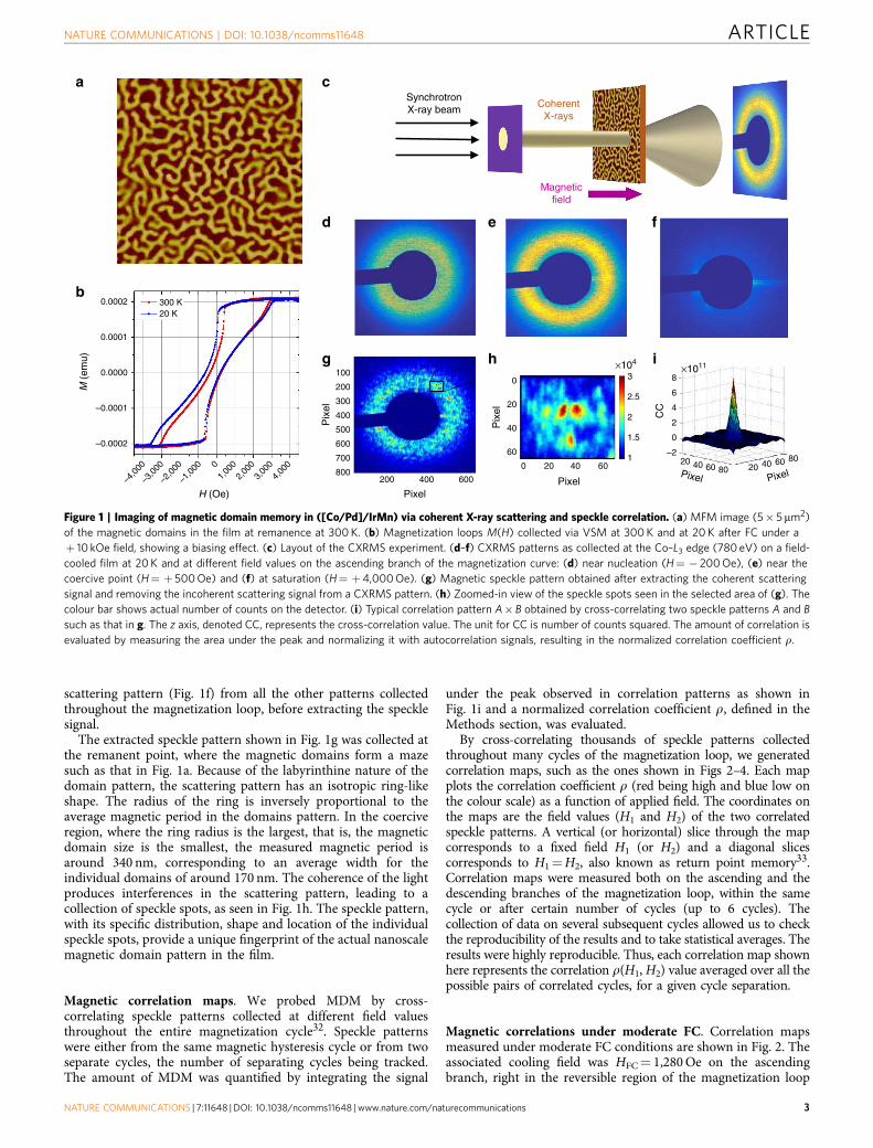
scattering pattern (Fig. 1f) from all the other patterns collectedthroughout the magnetization loop, before extracting the specklesignal.
The extracted speckle pattern shown in Fig. 1g was collected atthe remanent point, where the magnetic domains form a mazesuch as that in Fig. 1a. Because of the labyrinthine nature of thedomain pattern, the scattering pattern has an isotropic ring-likeshape. The radius of the ring is inversely proportional to theaverage magnetic period in the domains pattern. In the coerciveregion, where the ring radius is the largest, that is, the magneticdomain size is the smallest, the measured magnetic period isaround 340 nm, corresponding to an average width for theindividual domains of around 170 nm. The coherence of the lightproduces interferences in the scattering pattern, leading to acollection of speckle spots, as seen in Fig. 1h. The speckle pattern,with its specific distribution, shape and location of the individualspeckle spots, provide a unique fingerprint of the actual nanoscalemagnetic domain pattern in the film.
Magnetic correlation maps. We probed MDM by cross-correlating speckle patterns collected at different field valuesthroughout the entire magnetization cycle32. Speckle patternswere either from the same magnetic hysteresis cycle or from twoseparate cycles, the number of separating cycles being tracked.The amount of MDM was quantified by integrating the signal
under the peak observed in correlation patterns as shown inFig. 1i and a normalized correlation coefficient r, defined in theMethods section, was evaluated.
By cross-correlating thousands of speckle patterns collectedthroughout many cycles of the magnetization loop, we generatedcorrelation maps, such as the ones shown in Figs 2–4. Each mapplots the correlation coefficient r (red being high and blue low onthe colour scale) as a function of applied field. The coordinates onthe maps are the field values (H1 and H2) of the two correlatedspeckle patterns. A vertical (or horizontal) slice through the mapcorresponds to a fixed field H1 (or H2) and a diagonal slicescorresponds to H1¼H2, also known as return point memory33.Correlation maps were measured both on the ascending and thedescending branches of the magnetization loop, within the samecycle or after certain number of cycles (up to 6 cycles). Thecollection of data on several subsequent cycles allowed us to checkthe reproducibility of the results and to take statistical averages. Theresults were highly reproducible. Thus, each correlation map shownhere represents the correlation r(H1, H2) value averaged over all thepossible pairs of correlated cycles, for a given cycle separation.
Magnetic correlations under moderate FC. Correlation mapsmeasured under moderate FC conditions are shown in Fig. 2. Theassociated cooling field was HFC¼ 1,280 Oe on the ascendingbranch, right in the reversible region of the magnetization loop
Magneticfield
CoherentX-rays
b
a
d e f
SynchrotronX-ray beam
cM
(em
u)
H (Oe)
0.0002
0.0001
0.0000
–0.0001
–0.0002
–4,0
00
–3,0
00
–2,0
00
–1,0
00 01,
000
2,00
03,
000
4,00
0
Pixel
g100
200
200
300
400
400
500
600
600
700
800 Pixel Pixel
×1011
CC
i8
6
4
2
0
–220 40 60 80 20 40 60 80
×104
0
20
40
60
0 20 40 60
PixelP
ixel
Pix
el
h3
2.5
2
1.5
1
300 K20 K
Figure 1 | Imaging of magnetic domain memory in ([Co/Pd]/IrMn) via coherent X-ray scattering and speckle correlation. (a) MFM image (5� 5mm2)
of the magnetic domains in the film at remanence at 300 K. (b) Magnetization loops M(H) collected via VSM at 300 K and at 20 K after FC under a
þ 10 kOe field, showing a biasing effect. (c) Layout of the CXRMS experiment. (d–f) CXRMS patterns as collected at the Co–L3 edge (780 eV) on a field-
cooled film at 20 K and at different field values on the ascending branch of the magnetization curve: (d) near nucleation (H¼ � 200 Oe), (e) near the
coercive point (H¼ þ 500 Oe) and (f) at saturation (H¼ þ4,000 Oe). (g) Magnetic speckle pattern obtained after extracting the coherent scattering
signal and removing the incoherent scattering signal from a CXRMS pattern. (h) Zoomed-in view of the speckle spots seen in the selected area of (g). The
colour bar shows actual number of counts on the detector. (i) Typical correlation pattern A� B obtained by cross-correlating two speckle patterns A and B
such as that in g. The z axis, denoted CC, represents the cross-correlation value. The unit for CC is number of counts squared. The amount of correlation is
evaluated by measuring the area under the peak and normalizing it with autocorrelation signals, resulting in the normalized correlation coefficient r.
NATURE COMMUNICATIONS | DOI: 10.1038/ncomms11648 ARTICLE
NATURE COMMUNICATIONS | 7:11648 | DOI: 10.1038/ncomms11648 | www.nature.com/naturecommunications 3

(Fig. 2a). The resulting correlation maps for the descendingbranch (Fig. 2b) and for the ascending branch (Fig. 2c) show avery high correlation degree r approaching 100% in the centralregion. The high MDM extends over a wide plateau across themap, centred about H1¼H2¼H*B2,000 Oe. This result persiststhroughout field cycling. Even after many cycles, the map isunchanged, as slices in Fig. 2d–g indicate. On the diagonal slices(H1¼H2), r is close to 100% over the entire range of field. On thevertical slices at H1¼H*, r reaches nearly 100% over a wideplateau extending from B1,000 to 3,000 Oe. In that part of themagnetization loop, the magnetic domain pattern remainstopologically close to the one at H*. When the diagonal slice isperformed on the same cycle maps, it is expected that r¼ 100%,as, by definition, speckle patterns are correlated with themselves,
but we find here that diagonally slicing subsequent maps also leadto rB100%. This suggests that during the magnetization process,magnetic domains nucleate, propagate and collapse following thesame morphological path, guided by the template imprinted inthe AF layer. This result using a moderate HFC¼ 1,280 Oe coolingfield agrees very well with results obtained in ZFC conditionswhen HFC¼ 0. Similar to HFC¼ 0, a moderate cooling fieldHFC¼ 1,280 Oe leads to high MDM approaching 100% over alarge field range27 and also shows persistence through fieldcycling34.
Magnetic correlations under high FC. A selection of correlationmaps measured under high FC conditions is shown in Fig. 3. Theassociated cooling field was HFC¼ 3,200 Oe on the ascendingbranch (with the cooling starting at 400 K), that is, nearsaturation. The resulting correlation maps show a clear loss ofMDM in the central region of the magnetization loop. Correla-tion maps measured within the same cycle (Fig. 3a,b) still showsome high correlation but not extending as much as for lowercooling field values. Here, the high correlation is concentrated ona narrow region along the diagonal (H1¼H2). In addition, assoon as one cycle has been completed, the correlation drasticallydrops to as low as 40% in the central region of the map (Fig. 3c,d).The loss of MDM occurs similarly on the ascending anddescending branches. Both diagonal and vertical slices (Fig. 3e,f)through the maps clearly show the drastic drop in r, from 100%to B50%, after one cycle. During subsequent cycles, r continuesto gradually drop, from B50% down to 40% after three cycles.
HFC
a
d
f
c
e
�
�
H2
(Oe)
H (Oe)
b3,000
2,000
1,000
0
M (
emu)
�1
0.8
0.6
0.4
0.2
0
H (Oe) H (Oe)
–H *
–H * H *
H1 (Oe) H1 (Oe)
H2
(Oe)
0
–1,000
–2,000
–3,000
H *
g
�
�
0.0002
0.0001
–0.0001
0.0000
–0.0002
–4,0
00
–3,0
00
–1,0
00
–2,0
00 01,
000
2,00
03,
000
1,00
0
–4,0
00
–3,5
00
–3,0
00
–2,5
00
–2,0
00
–1,5
00
–1,0
00–5
00
–4,0
00
–3,5
00
–3,0
00
–2,5
00
–2,0
00
–1,5
00
–1,0
00–5
00
0
0
500
1,00
01,
5002,
0002,
5003,
0003,
5004,
000
–500 50
001,
0001,
5002,
0002,
5003,
0003,
5004,
000
1
0.8
0.6
0.4
0.2
0
1
0.8
0.6
0.4
0.2
0
1
0.8
0.6
0.4
0.2
0
1
0.8
0.6
0.4
0.2
0
D0D1D2D3
A0A1A2A3
D0D1D2D3
A0A1A2A3
Figure 2 | Correlations maps and slices measured at 20 K after FC under
HFC¼ 1,280 Oe. (a) Magnetization curve M(H) at 20 K after FC under
HFC¼ þ 1,280 Oe, a field point indicated by the blue dot on the curve.
(b,c) Correlation maps r(H1, H2) for one cycle separation (the correlation
coefficient r is plotted in colour, where red is high and blue is low)
measured along (b) the descending branch and (c) the ascending branch.
(d,e) Diagonal slices, for which H1¼H2 (dotted line). (f,g) Vertical slices
through the maps at H1¼H* (dashed line). These graphs show slices
through successive correlation maps, using the notation A0, A1y D0, D1
and so on. In this notation, the letter A stands for the ascending branch, the
letter D stands for the descending branch and the index corresponds to the
number of cycles separating the two correlated images. For example, D3
shows correlation between two descending branches that are separated by
three full cycles. In each map/slice, the plotted coefficient r is an average
value over many cycles at a fixed cycle separation.
Ascending branchDescending brancha
fe
dc
H (Oe)H (Oe)
0
–1,000
–2,000
–3,000
–4,0000
–1,000
–2,000
–3,000
–4,000
H2
(Oe)
H2
(Oe)
H2
(Oe)
H2
(Oe)
4,000
3,000
2,000
1,000
0
0
–500
b
4,000
4,00
0
3,000
3,00
0
2,000
2,00
0
1,000
1,00
0
04,
000
3,00
02,
000
1,00
0
0
–500
�
H1 (Oe) H1 (Oe)
� �
–4,0
00
–3,0
00
–2,0
00
–1, 0
00 0
–4,0
00
–3,0
00
–2,0
00
–1,0
00
1
0.9
0.8
0.7
0.6
0.5
0.4
0.3
0.2
0.1
0
1
0.8
0.6
0.4
0.2
1
0.8
0.6
0.4
0.2
D0D1D2D3
A0A1A2A3
Figure 3 | Correlations maps and slices measured at 20 K after FC under
HFC¼ 3,200 Oe. (a,b) Correlation maps r(H1, H2) measured within the
same cycle on the descending and ascending branches, respectively.
(c,d) Correlation maps r(H1, H2) measured at one cycle separation.
(e,f) Vertical slices at H1¼H* (along the dashed line). These graphs show
slices through successive correlation maps, using the notation A0, A1y
D0, D1 and so on. In this notation, the letter A stands for the ascending
branch, the letter D stands for the descending branch and the index
corresponds to the number of cycles separating the two correlated images.
ARTICLE NATURE COMMUNICATIONS | DOI: 10.1038/ncomms11648
4 NATURE COMMUNICATIONS | 7:11648 | DOI: 10.1038/ncomms11648 | www.nature.com/naturecommunications

The maps show a higher correlation at the four corners, whenH1 and H2 are both near one extremity, either nucleation(HB� 500 Oe on ascending branch) or saturation (HB4,000 Oe).The occurrence of a high correlation at all the four corners of thecorrelation map indicates that the magnetic domain pattern atsaturation is correlated with the magnetic domain pattern atnucleation. This interesting correlation emerges when the coolingfield is high, nearly saturating. In such cooling conditions, thedomain pattern imprinted in the AF layer via the uncompensatedspins is made of small isolated domains, sparsely scatteredthroughout the film. Owing to the exchange coupling, these sparsedomains in the AF layer then tend to drive the topology ofmagnetic domains in the F layer when they are nucleating but alsowhen they are approaching saturation. Therefore, the magneticdomain topology in the F layer at nucleation and at saturation bothtend to match quite well the imprinted pattern. Consequently, notonly correlation is high at the corners on the main diagonal of themap (when both H1 and H2 are close to nucleation or when theyare both close to saturation) but also at the two other off-diagonalcorners (when H1 is close to nucleation and H2 is close tosaturation, and vice versa). The F magnetic domain patterns at allthe four corners of the map all resemble the one pattern imprintedin the AF layer during the cooling.
Dependence with cooling field magnitude. The dependence ofMDM with cooling field HCF is shown in Fig. 4. Figure 4a–ddisplays correlation maps measured on the ascending branchafter one cycle for various HCF values increasing from 0 to3,200 Oe. Associated diagonal slices are shown in Fig. 4e–h.In ZFC condition or when the magnitude of the cooling field ismoderate, that is, HFC¼ 0 to B2,250 Oe, the film exhibits highMDM over an extended region throughout the magnetizationcycle, and that high MDM is persistent through field cycling.The domain reversal is then mostly driven by the templateimprinted in the AF IrMn layer. In ZFC conditions, the templateimprinted in the AF layer has about the same amount of up anddown domains, and nearly no net magnetization (coercivepattern). When propagating, the domains in the F layer tend toretrieve that particular template, very quickly after nucleation andalmost all the way to saturation. Surprisingly, FC the sampleunder a moderate non-zero field, thus applying a significant bias,still leads to results similar to ZFC: high MDM extends throughmost of the magnetization cycle and persists through field cycling.Even when applying a significant net bias with a higher coolingfield up to HFC¼ 2,250 Oe, the imprinted domain patterns stillguide the domain topology at the coercive point.
When the cooling field is increased to higher values, that is,HFCB2,500 Oe and beyond, a dramatic loss of MDM occurs overnearly the entirety of the magnetization loop and the lossgradually progresses with field cycling. When HFCB2,500 Oe(Fig. 4c), the MDM is still strong, around 90%, on the nucleationside, but gradually decreases down to B65% as the magnetizationprogresses. In this case, the film shows a moderately high MDMplateau extending throughout most of the magnetization cycle.The average height of this plateau decreases with field cycling,from B75% after one cycle down to 55% after six cycles (Fig. 4g).
When HFC¼ 3,200 Oe (Fig. 4d), the film shows very low or nomemory, except at the very corners of the map where the film iseither at nucleation or near saturation. At such high HFC values,the imprinted domain pattern differs significantly from thecoercive pattern. Many domains have already collapsed, leavingonly a few sparse domains in the imprinted template.Consequently, the domain reversal in the F layer is mostlyrandom and MDM is low for most of the magnetization process.However, the remaining uncollapsed domains in the imprinted
template still play the role of anchors for the nucleation processand somewhat guide the final path to saturation. This causesMDM to be relatively high (up to 80%) at the extremities of themagnetization process (nucleation and saturation) but low (downto 40%) in between these points (Fig. 4h). Therefore, field coolingwith a nearly saturating field (HFCB3,000 Oe) can still inducehigh MDM at the extremities of the magnetization process.
Interestingly, high correlation is also observed at the corners oflower HFC maps. For these lower cooling field cases, the highcorrelation in the central region extends flat towards the cornersof the maps. The persistence of high correlation at the cornerssuggests the possible presence of distributions in the exchangecoupling, which tend to shape the imprinted domain pattern,favouring some locations for domains to nucleate and to latervanish when approaching saturation. In other terms, exchange
110.9
0.8 0.80.70.6 0.60.50.4 0.40.30.2 0.2
0.10
0
1
0.8
0.6
0.4
0.2
0
1
0.8
0.6
0.4
0.2
0
1
0.8
0.6
0.4
0.2
0
H2
(Oe)
H2
(Oe)
H2
(Oe)
H2
(Oe)
H1 (Oe) H1 (Oe)
a
b
c
d
e
f
g
h
�
�
�
�
�
�3,500
3,50
0
3,000
3,00
03,
000
2,500
2,50
0
2,000
2,00
02,
000
1,500
1,50
0
1,000
1,00
01,
000
500
500
0
3,5003,0002,5002,0001,5001,000
5000
3,500
3,50
0
4,000
4,00
04,
000
3,000
3,00
03,
000
2,500
2,50
0
2,000
2,00
02,
000
1,500
1,50
0
1,000
1,00
01,
000
500
500
–5000
3,5004,000
3,0002,5002,0001,5001,000
500
–5000
0 0
3,50
04,
000
4,00
0
3,00
03,
000
2,50
02,
000
2,00
0
1,50
01,
000
1,00
0
–1,0
0050
00 0
4,00
03,
000
2,00
01,
000
–1,0
00 0
3,50
04,
000
3,00
02,
500
2,00
0
1,50
01,
000
5000
00
A0
A1
A2
A0
A1
A2
A3
A4
A0A1A2A3A4A5A6
A0
A1
A2
A3
Figure 4 | Dependence of correlation maps and associated diagonal
slices with cooling field HFC. (a–d) Correlation maps r(H1, H2) measured at
20 K on the ascending branch after one cycle (A1 map) under different
cooling fields HFC (cooling starting at 400 K): (a) HFC¼0 (ZFC);
(b) HFC¼ 2,240 Oe; (c) HFC¼ 2,560 Oe; and (d) HFC¼ 3,200 Oe.
(e–h) Associated diagonal slices through the maps along the dotted line.
Each graph includes several measured cycles (up to six cycles for
HFC¼ 2,560 Oe) using the notation A0, A1, A2 and so on. In this notation,
the letter A stands for the ascending branch and the index corresponds to
the number of cycles separating the two correlated images.
NATURE COMMUNICATIONS | DOI: 10.1038/ncomms11648 ARTICLE
NATURE COMMUNICATIONS | 7:11648 | DOI: 10.1038/ncomms11648 | www.nature.com/naturecommunications 5
coupling is still the main driving force leading to magneticmemory in this material but the presence of distributions canadditionally extend the high memory from the core of themagnetization cycle towards the nucleation and saturationextremities.
Finally, we attempted complementary measurements at the MnL3-edge (638 eV) in a hope to directly measure a magnetic signalfrom the interfacial uncompensated Mn spins in the IrMnlayer and correlate it to the signal produced by the Co spins in the[Co/Pd] multilayer at the Co edge. Unfortunately, no signalcould be observed at the Mn edge. Indeed, the amount ofuncompensated Mn spins in the IrMn layer (presumably only afew percent of the total amount of Mn in the film15,35) is toosmall to produce a visible magnetic signal in a reasonable timeframe given the sensitivity of the detector.
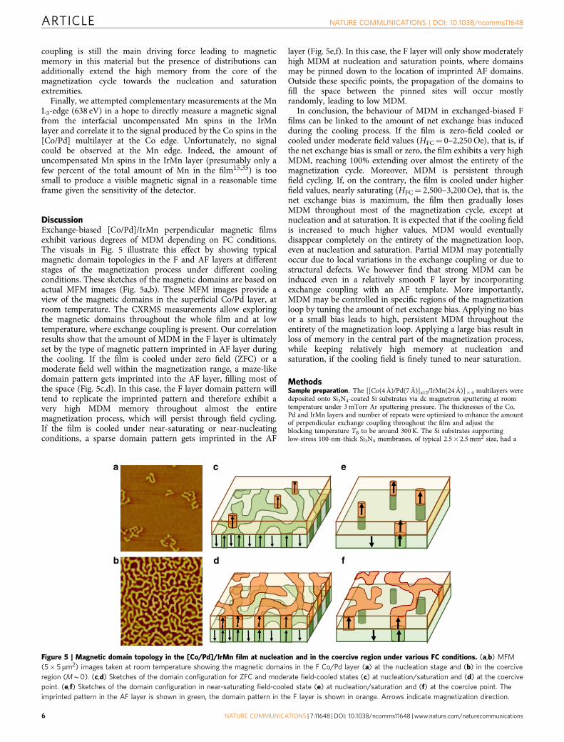
DiscussionExchange-biased [Co/Pd]/IrMn perpendicular magnetic filmsexhibit various degrees of MDM depending on FC conditions.The visuals in Fig. 5 illustrate this effect by showing typicalmagnetic domain topologies in the F and AF layers at differentstages of the magnetization process under different coolingconditions. These sketches of the magnetic domains are based onactual MFM images (Fig. 5a,b). These MFM images provide aview of the magnetic domains in the superficial Co/Pd layer, atroom temperature. The CXRMS measurements allow exploringthe magnetic domains throughout the whole film and at lowtemperature, where exchange coupling is present. Our correlationresults show that the amount of MDM in the F layer is ultimatelyset by the type of magnetic pattern imprinted in AF layer duringthe cooling. If the film is cooled under zero field (ZFC) or amoderate field well within the magnetization range, a maze-likedomain pattern gets imprinted into the AF layer, filling most ofthe space (Fig. 5c,d). In this case, the F layer domain pattern willtend to replicate the imprinted pattern and therefore exhibit avery high MDM memory throughout almost the entiremagnetization process, which will persist through field cycling.If the film is cooled under near-saturating or near-nucleatingconditions, a sparse domain pattern gets imprinted in the AF
layer (Fig. 5e,f). In this case, the F layer will only show moderatelyhigh MDM at nucleation and saturation points, where domainsmay be pinned down to the location of imprinted AF domains.Outside these specific points, the propagation of the domains tofill the space between the pinned sites will occur mostlyrandomly, leading to low MDM.
In conclusion, the behaviour of MDM in exchanged-biased Ffilms can be linked to the amount of net exchange bias inducedduring the cooling process. If the film is zero-field cooled orcooled under moderate field values (HFC¼ 0–2,250 Oe), that is, ifthe net exchange bias is small or zero, the film exhibits a very highMDM, reaching 100% extending over almost the entirety of themagnetization cycle. Moreover, MDM is persistent throughfield cycling. If, on the contrary, the film is cooled under higherfield values, nearly saturating (HFC¼ 2,500–3,200 Oe), that is, thenet exchange bias is maximum, the film then gradually losesMDM throughout most of the magnetization cycle, except atnucleation and at saturation. It is expected that if the cooling fieldis increased to much higher values, MDM would eventuallydisappear completely on the entirety of the magnetization loop,even at nucleation and saturation. Partial MDM may potentiallyoccur due to local variations in the exchange coupling or due tostructural defects. We however find that strong MDM can beinduced even in a relatively smooth F layer by incorporatingexchange coupling with an AF template. More importantly,MDM may be controlled in specific regions of the magnetizationloop by tuning the amount of net exchange bias. Applying no biasor a small bias leads to high, persistent MDM throughout theentirety of the magnetization loop. Applying a large bias result inloss of memory in the central part of the magnetization process,while keeping relatively high memory at nucleation andsaturation, if the cooling field is finely tuned to near saturation.
MethodsSample preparation. The [[Co(4 Å)/Pd(7 Å)]x12/IrMn(24 Å)]� 4 multilayers weredeposited onto Si3N4-coated Si substrates via dc magnetron sputtering at roomtemperature under 3 mTorr Ar sputtering pressure. The thicknesses of the Co,Pd and IrMn layers and number of repeats were optimized to enhance the amountof perpendicular exchange coupling throughout the film and adjust theblocking temperature TB to be around 300 K. The Si substrates supportinglow-stress 100-nm-thick Si3N4 membranes, of typical 2.5� 2.5 mm2 size, had a
c
d
a
b f
e
Figure 5 | Magnetic domain topology in the [Co/Pd]/IrMn film at nucleation and in the coercive region under various FC conditions. (a,b) MFM
(5� 5 mm2) images taken at room temperature showing the magnetic domains in the F Co/Pd layer (a) at the nucleation stage and (b) in the coercive
region (MB0). (c,d) Sketches of the domain configuration for ZFC and moderate field-cooled states (c) at nucleation/saturation and (d) at the coercive
point. (e,f) Sketches of the domain configuration in near-saturating field-cooled state (e) at nucleation/saturation and (f) at the coercive point. The
imprinted pattern in the AF layer is shown in green, the domain pattern in the F layer is shown in orange. Arrows indicate magnetization direction.
ARTICLE NATURE COMMUNICATIONS | DOI: 10.1038/ncomms11648
6 NATURE COMMUNICATIONS | 7:11648 | DOI: 10.1038/ncomms11648 | www.nature.com/naturecommunications

1� 1 mm2 square opening at their centre, to allow measurements with X-rays intransmission geometry. A circular pinhole of 20 mm in diameter was mounted ontop of the film and positioned within the 1� 1 mm2 square opening. In thescattering experiment, the film-pinhole element was inserted with the pinholefacing the upstream X-ray beam, so as to achieve nearly coherent illuminationof the film.
Coherent X-ray magnetic scattering experiment. Our CXRMS measurementswere carried out at the Advanced Light Source synchrotron, at the coherentsoft X-ray beamline BL12.0.2 (ref. 30). The energy of the light was tuned tothe magnetic resonance at the Co L3-edge to optimize the magneto-opticalcontrast36–38. These CXRMS measurements were conducted with linearly polarizedlight. The polarization of the X-ray light produced by the U8 undulator wastransverse linear in the horizontal plane (s-polarization). The sample was mountedin transmission geometry so that its magnetization vector M was parallel to thedirection k of the incident light and perpendicular to the polarization. In thisconfiguration, the resulting magnetic scattering signal occurs in the s� p channelonly (where p denotes the transverse vertical polarization) and its amplitude isdirectly proportional to the dot product k.M36. The charge scattering signal, on theother hand, remains in the s�s channel and does not interfere with the magneticscattering. The resulting overall scattering is a simple superposition of the purecharge- and magnetic-scattering intensities. When saturating the magnetic film, themagnetic scattering component gets suppressed, leaving only the charge-scatteringintensity. This reference signal is later subtracted from all the other scatteringimages collected throughout the magnetization loop before extracting the magneticspeckle signal. However, we note that, in our films, the structures are very uniformlaterally; thus, there is very little charge scattering and any charge scattering occursat a very different q range compared with the magnetic scattering. Regardingcoherence properties, the X-ray beam was spatially filtered by a 20-mm pinhole toimprove its transverse coherence and limit the area of the sample probed. Over theilluminated area, about a 20-mm-diameter disk, the coherence of the X-ray beam ispartial. At this energy (778 eV), the transverse coherence length of the X-ray beamis B5 mm30. We have estimated that the associated degree of coherence29 in ourspeckle patterns is B15–20%. This partial coherence proves not to be a limitingfactor in our cross-correlation work. In our analysis, we separate the purelycoherent signal from the incoherent signal before the correlations, by using aniterative smoothing technique32. The smoothed scattering patterns, whichessentially represents the incoherent part of the scattering signal, are subtractedfrom the collected scattering images so as to only leave the purely coherent part ofthe scattering signal (speckle). We then perform our cross-correlations directly onthe speckle patterns. This approach enables us to evaluate MDM with a goodaccuracy and no information is lost due to the partial coherence of the light.
Speckle cross-correlation technique. The amount of correlation between twospeckle images is evaluated through a normalized correlation coefficient defined asfollows:
r ¼
Pi;j
A�Bð Þi;jffiffiffiffiffiffiffiffiffiffiffiffiffiffiffiffiffiffiffiffiffiffiffiffiffiffiffiffiffiffiffiffiffiffiffiffiffiffiffiffiffiffiffiffiffiffiPi;j
A�Að Þi;jPi;j
B�Bð Þi;jr
where A and B represent the two speckle patterns to be correlated and� represents the correlation operation32. The correlation patterns A�B, A�Aand B�B are two-dimensional images of same size than images A and B (anexample of such correlation pattern is shown in Fig. 1i, a close-up). Correlationspatterns usually exhibit a peak whose width corresponds to the average speckle sizeand whose intensity reflects the amount of correlation between the specklepatterns. The indices (i,j) refer to pixel positions in these correlation patterns, sothat the summation
Pallows integrating the signal under the correlation peak.
This integration is performed both on the cross-correlated signal A�B and theauto-correlated signals A�A and B�B for normalization purposes. The resultingcoefficient r lies between 0 and 100%. The maximum value is reached when thetwo speckle patterns A and B, and consequently their associated magnetic domainpatterns, are nearly identical.
References1. Ackermann, J. Toward a universal memory. Science 308, 508–510 (2005).2. Chappert, C., Fert, A. & Nguyen Van Dau, F. The emergence of spin electronics
in data storage. Nat. Mater. 6, 813–823 (2007).3. Fert, A. Nobel lecture: origin, development, and future of spintronics.
Rev. Mod. Phys. 80, 1517–1530 (2008).4. Jansen, R. Silicon spintronics. Nat. Mater. 11, 400–408 (2012).5. Hu, B. et al. Study of Co/Pd multilayers as a candidate material for next
generation magnetic media. J. Appl. Phys. 109, 034314 (2011).6. Miron, I. et al. Perpendicular switching of a single ferromagnetic layer induced
by in-plane current injection. Nature 476, 189–194 (2011).7. Lambert, C.-H. et al. Quantifying perpendicular magnetic anisotropy at the
Fe-MgO(001) interface. Appl. Phys. Lett. 102, 122410 (2013).
8. Gottwald, M. et al. Ultra-thin Co/Pd multilayers with enhanced high-temperature annealing stability. Appl. Phys. Lett. 102, 052405 (2013).
9. Stavrou, E. & Roll, K. Magnetic anisotropy in Gd/(FeCo) and Gd/Fe multilayersfor high density magnetic recording. J. Appl. Phys. 85, 5971–5973 (1999).
10. Sbiaa, R., Meng, H. & Piramanayagam, S. N. Materials with perpendicularmagnetic anisotropy for magnetic random access memory. Phys. Stat. Solid.RRL 5, 413–419 (2011).
11. Lee, J. et al. Scaling dependence and tailoring of the pinning field in FePt-basedexchange coupled composite media. Nanotechnology 25, 045604 (2014).
12. Barnes, S. E., Ieada, J. & Maekawa, S. Magnetic memory and currentamplification devices using moving domain walls. Appl. Phys. Lett. 89, 122507(2006).
13. Kirk, T. L., Hellwig, O. & Fullerton, E. E. Coercivity mechanisms in positiveexchange-biased Co films and Co/Pt multilayers. Phys. Rev. B 65, 224426(2002).
14. Davies, J. E. et al. Magnetization reversal of Co/Pt multilayers: microscopicorigin of high-field magnetic irreversibility. Phys. Rev. B 70, 224434 (2004).
15. Kappenberger, K. et al. Direct imaging and determination of theuncompensated spin density in exchange-biased CoO/CoPt multilayers. Phys.Rev. Lett. 91, 267202 (2003).
16. Skuza, J. R., Clavero, C., Yang, K., Wincheski, B. & Lukaszew, R. A.Microstructural magnetic anisotropy and magnetic domain structurecorrelations in expitaxial FePd thin films with perpendicular magneticanisotropy. IEE Trans. Magn. 46, 1886–1889 (2010).
17. Paramanayagam, S. N., Ranjbar, M., Sbiaa, R., Tavakkoli, K. G. & Chong, T. C.Characterization of high-density bit patterned media using ultra-highresolution magnetic force microscopy. Phys. Stat. Solid. RRL 6, 141–143 (2012).
18. Liu, Z., Zhou, S. M. & Jiao, X. B. Correlation between perpendicular magneticanisotropy and microstructure in TbFeCo and TbFeCo-SiO2 films. J. Phys. D:Appl. Phys. 42, 015008 (2009).
19. Kortright, J. B. et al. Research frontiers in magnetic materials at soft X-raysynchrotron facilities. J. Magn. Magn. Mater. 207, 7–44 (1999).
20. Hellwig, O., Denbeaux, G. P., Kortright, J. B. & Fullerton, E. E. X-ray studiesof aligned magnetic strip domains in perpendicular multilayers. Phys. B 336,136–144 (2003).
21. Fischer, P., Im, M.-Y., Eimuller, T., Schutz, G. & Shin, S.-C. Magnetizationreversal behavior of nanogranular CoCrPt alloy thin films studied withmagnetic transmission X-ray microscopy. J. Magn. Magn. Mater. 286, 311–314(2005).
22. Hellwig, O., Berger, A., Kortright, J. B. & Fullerton, E. E. Domain structure andmagnetization reversal of antiferromagnetically coupled perpendicularanisotropy films. J. Magn. Magn. Mater. 319, 13–55 (2007).
23. Pierce, M. S. et al. Disorder-induced microscopic magnetic memory. Phys. Rev.Lett. 94, 017202 (2005).
24. Pierce, M. S. et al. Disorder-induced microscopic magnetic memory:experiments and theories. Phys. Rev. B 75, 144406 (2007).
25. Chesnel, K., Fullerton, E. E., Carey, M. J., Kortright, J. B. & Kevan, S. D.Magnetic memory in ferromagnetic thin films via exchange coupling. Phys. Rev.B 78, 132409 (2008).
26. Chesnel, K., Nelson, J., Kevan, S. D., Carey, M. J. & Fullerton, E. E. Oscillatingspatial dependence of domain memory in ferromagnetic films mapped via x-rayspeckle correlation. Phys. Rev. B 83, 054436 (2011).
27. Chesnel, K., Wilcken, B., Rytting, M., Kevan, S. D. & Fullerton, E. E. Fieldmapping and temperature dependence of magnetic domain memory inducedby exchange couplings. New J. Phys. 15, 023016 (2013).
28. Maat, S., Takano, K., Parkin, S. S. P. & Fullerton, E. E. Perpendicular exchangebias of Co/Pt multilayers. Phys. Rev. Lett 87, 087202 (2001).
29. Chesnel, K. et al. Soft X-ray magnetic speckles from a nanostructured FePdwire. Phys. Rev. B 66, 172404 (2002).
30. Chesnel, K., Turner, J. J., Pfeifer, M. & Kevan, S. D. Probing complex materialswith coherent X-rays. Appl. Phys. A 92, 431–437 (2008).
31. Pierce, M. S. et al. The influence of structural disorder on magnetic domainformation in perpendicular anisotropy thin films. Phys. Rev. B 87, 184428(2013).
32. Chesnel, K., Nelson, J., Wilcken, B. & Kevan, S. D. Mapping spatial and fielddependence of magnetic domain memory by soft X-ray speckle metrology.J. Synch. Rad. 19, 293–306 (2012).
33. Pierce, M. S. et al. Quasistatic X-ray speckle metrology of microscopic magneticreturn-point memory. Phys. Rev. Lett. 90, 175502 (2003).
34. Nelson, J., Wilcken, B. & Chesnel, K. Persistence of magnetic domain memorythrough field cycling in exchange biased thin films. J. Utah Acad. Sci. 87,267–274 (2010).
35. Tsunoda, M. et al. Uncompensated antiferromagnetic spins at the interface inMn-Ir based exchange biased bilayers. J. Appl. Phys. 101, 09E510 (2007).
36. de Bergevin, F. & Brunel, M. Diffraction of X-rays by magnetic materials. Acta.Cryst. A 37, 314–324 (1981).
37. Hannon, J. P., Trammell, G. T., Blume, M. & Gibbs, D. X-ray resonanceexchange scattering. Phys. Rev. Lett. 61, 1245–1248 (1988).
NATURE COMMUNICATIONS | DOI: 10.1038/ncomms11648 ARTICLE
NATURE COMMUNICATIONS | 7:11648 | DOI: 10.1038/ncomms11648 | www.nature.com/naturecommunications 7

38. Kortright, J. B. et al. Soft X-ray small-angle scattering as a sensitive probe ofmagnetic and charge heterogeneity. Phys. Rev. B 64, 092401 (2001).
AcknowledgementsThis work, including the VSM and MFM measurements, as well as the collection andanalysis of the synchrotron scattering data, was supported by internal ORCA and MEGgrants at BYU. Correlation work was supported by time on supercomputer Marylou atBYU. Work at UCSD on sample fabrication and characterization, as well as discussion ofthe results was supported by the research programmes of the US Department of Energy(DOE), office of Basic Energy Sciences (Award Number DE-SC0003678). The scatteringdata were collected at the Advance Light Source, a US DOE Office of Science UserFacility operated by the Lawrence Berkeley National Laboratory. We thank Steve Kevanfor facility support with the coherent scattering chamber at the ALS.
Author contributionsThis study was conceived by K.C. and E.E.F. E.E.F. synthesized and characterized themagnetic thin films. K.C. conducted the study, collected the coherent X-ray scatteringimages at the ALS, the magnetometry data and the MFM images at BYU. A.S. and M.R.analysed the scattering images and computed the speckle correlation maps. K.C. gathered
all the maps and slices, and interpreted the results. E.E.F. provided feedback on theresults. K.C. wrote the paper with feedback from all the authors.
Additional informationCompeting financial interests: The authors declare no competing financial interests.
Reprints and permission information is available online at http://npg.nature.com/reprintsandpermissions/
How to cite this article: Chesnel, K. et al. Shaping nanoscale magnetic domainmemory in exchange-coupled ferromagnets by field cooling. Nat. Commun. 7:11648doi: 10.1038/ncomms11648 (2016).
This work is licensed under a Creative Commons Attribution 4.0International License. The images or other third party material in this
article are included in the article’s Creative Commons license, unless indicated otherwisein the credit line; if the material is not included under the Creative Commons license,users will need to obtain permission from the license holder to reproduce the material.To view a copy of this license, visit http://creativecommons.org/licenses/by/4.0/
ARTICLE NATURE COMMUNICATIONS | DOI: 10.1038/ncomms11648
8 NATURE COMMUNICATIONS | 7:11648 | DOI: 10.1038/ncomms11648 | www.nature.com/naturecommunications