
Shake Table Tests and Numerical Modeling of Seismically Isolated ... · SHAKE TABLE TESTS AND...
15
13 th World Conference on Earthquake Engineering Vancouver, B.C., Canada August 1-6, 2004 Paper No. 1780 SHAKE TABLE TESTS AND NUMERICAL MODELING OF SEISMICALLY ISOLATED RAILWAY BRIDGES Hirokazu IEMURA 1 , Shuji IWATA 2 ,Kiyomitsu MURATA 3 SUMMARY In the implementation of seismic isolation system to railway bridges, the basic requirements are as follows. The first is to secure the running safety of trains under occasional earthquake (Level 1) ground motion. For this purpose, the isolation bearings should work almost like fixed hinges not to allow large displacement. The second is to protect bridge piers from severe damage under rare earthquake (Level 2) ground motion. For this purpose, the isolation bearings should play their roles effectively to add flexibility and damping capability to railway bridge systems. It is also expected to come back to the original position after severe earthquake motion is over, to maintain the function of the train operation. To satisfy above mentioned requirements, accurate estimation of dynamic behavior of the seismically isolated bridge structures is necessary. Especially, complicated constraining force from the railway track to the bridges girder has to be accurately investigated and modeled. For this purpose, shake table tests of partial models of railway bridge structures are conducted subjected to different types and levels of earthquake ground motion. The direct measurement of the constraining force to the girder is almost impossible, so, in this study, it is detected from the equilibrium of dynamic motion of the system using displacement and acceleration data of the tests. The nonlinear and non-symmetric constraining force is found first time in this field. The numerical models are proposed based on the experimental results. The numerical simulation of the isolated bridge structures with the proposed models agrees with experimental results fairly well, suggesting that the proposed models can be used for structural design process for new construction and seismic retrofit of existing railway bridges. INTRODUCTION Hyogo-ken Nanbu Earthquake, which hit the western part of Japan on January 17 in 1995, gave serious damage to the traffic facilities. After the earthquake, the seismic design code was examined at a technical committee steered by Japanese Ministry of Transport. The research works have been performed aiming at 1 Kyoto University, Department of Civil Engineering Systems, Professor, Dr. Eng. Yoshida-honmachi, Sakyo-ku, Kyoto 606-8501, Japan 2 Central Japan Railway Company, Technical Research and Development Department Chief Eng., Dr. Eng. 1545-33 Ohyama, Komaki, 485-0801, Japan 3 Railway Technical Research Institute, Steel &Hybrid Structure Lab., Chief Researcher, Dr. Eng. 2-8-38, Hikari-cho, Kokubunji-shi, Tokyo 185-8540, Japan
Transcript of Shake Table Tests and Numerical Modeling of Seismically Isolated ... · SHAKE TABLE TESTS AND...

13th World Conference on Earthquake Engineering Vancouver, B.C., Canada
August 1-6, 2004 Paper No. 1780
SHAKE TABLE TESTS AND NUMERICAL MODELING OF SEISMICALLY ISOLATED RAILWAY BRIDGES
Hirokazu IEMURA1 , Shuji IWATA2,Kiyomitsu MURATA3
SUMMARY
In the implementation of seismic isolation system to railway bridges, the basic requirements are as follows. The first is to secure the running safety of trains under occasional earthquake (Level 1) ground motion. For this purpose, the isolation bearings should work almost like fixed hinges not to allow large displacement. The second is to protect bridge piers from severe damage under rare earthquake (Level 2) ground motion. For this purpose, the isolation bearings should play their roles effectively to add flexibility and damping capability to railway bridge systems. It is also expected to come back to the original position after severe earthquake motion is over, to maintain the function of the train operation. To satisfy above mentioned requirements, accurate estimation of dynamic behavior of the seismically isolated bridge structures is necessary. Especially, complicated constraining force from the railway track to the bridges girder has to be accurately investigated and modeled. For this purpose, shake table tests of partial models of railway bridge structures are conducted subjected to different types and levels of earthquake ground motion. The direct measurement of the constraining force to the girder is almost impossible, so, in this study, it is detected from the equilibrium of dynamic motion of the system using displacement and acceleration data of the tests. The nonlinear and non-symmetric constraining force is found first time in this field. The numerical models are proposed based on the experimental results. The numerical simulation of the isolated bridge structures with the proposed models agrees with experimental results fairly well, suggesting that the proposed models can be used for structural design process for new construction and seismic retrofit of existing railway bridges.
INTRODUCTION
Hyogo-ken Nanbu Earthquake, which hit the western part of Japan on January 17 in 1995, gave serious damage to the traffic facilities. After the earthquake, the seismic design code was examined at a technical committee steered by Japanese Ministry of Transport. The research works have been performed aiming at 1 Kyoto University, Department of Civil Engineering Systems, Professor, Dr. Eng.
Yoshida-honmachi, Sakyo-ku, Kyoto 606-8501, Japan 2 Central Japan Railway Company, Technical Research and Development Department Chief Eng., Dr. Eng. 1545-33 Ohyama, Komaki, 485-0801, Japan 3 Railway Technical Research Institute, Steel &Hybrid Structure Lab., Chief Researcher, Dr. Eng.
2-8-38, Hikari-cho, Kokubunji-shi, Tokyo 185-8540, Japan
an ideal seismic design. A new seismic design code of railway structures adopted the latest technology through the discussion extended over two years, and was made public as "Seismic Design Code for Railway Structures" in December 1998. This became systematization of the idea concerning a new seismic design of railway structures. In the new seismic design code, the ductility based design level of structural members is evaluated considering properties of the surface subsoil.
On the other hand, the devices with the effect of the seismic isolation such as rubber bearings and the dampers, have been adopted in railway bridges. The seismic isolation design, which had not been clearly described in the previous seismic design code, was prescribed for the first time. So, it will be necessary to investigate the seismic isolation of railway structures more in future. At the same time, it is important to secure the train running stability as a performance of railway structures under the state of daily services as well as of level 1 ground motion. Moreover, there remains an unknown issues on the dynamic behavior of track structures. These are special problems of railway structures in the application of seismic isolation systems.
As a research to apply the seismic isolation method to the railway structures for high seismic performance, it is necessary to investigate the dynamic interaction between the track and the railway bridge structure. And, the performance of the isolated railway bridge due to earthquake motion has to be accurately estimated for reasonable design. The experiment, using the large-scale strong earthquake simulator at Kyoto University, was performed for the investigation of the problems of these interactions. APPLICATION OF ISOLATION SYSTEM TO RAILWAY BRIDGES
The rubber bearing which is made of rubber bonded to the iron plate was invented by E. Freyssinet of France in 1956. The rubber bearing was used in a large-scale railway bridge (Kinugawa bridge: approximately 450m in total length) in Japan in 1961. Afterwards, the rubber bearing and the damper have been used for the railway bridge structures. However, "Seismic Isolation Design" (idea of reducing the shake of ground motions) has not been clearly defined in standard regulations. The description of seismic isolation was included in the new seismic design code for the first time.
In the seismic isolation design of railway bridges, there are two issues important to the railway. One is the train running stability. Because the train running stability should be secured under a usual state and the level 1 ground motion, the displacement is severely restricted to the railway structure. The seismic isolation design is defined as the design method by which the vibration of the ground can be softly absorbed by ①isolation function (elongation of the structural natural periods): function that bridge girder is softly supported in the horizontal direction with rubber bearings, ②damping function (performance of response reduction): function to absorb the energy of the earthquake input, and the structural vibration due to the ground motion. It means that the displacement of railway structure must be limited for the required , while the seismic isolation design has the characteristics which allows displacement. Therefore, the seismic isolation design of railway structures must satisfy the conflicting performance requirements.
Another problem originates from the track including the rail. On the railway structure, there is a track such as rails. When the external force acts on the track, the track structure generates the constraining force so that the shape is maintained. In the seismic isolation design in which the bridge girder is elastically supported, the constraining force of the track structure due to the seismic load influences the dynamic behavior of the structure. This did not pose a serious problem to the bridge structure with the conventional fixed bearings.
These interaction problems do not exist in the seismic isolation design of highway bridges and buildings. It is necessary to evaluate the influence of the constraining force to the track to establish an effective isolation system for railway bridges. For the service condition and the level 1 ground motion, displacement control mechanism is necessary to maintain the train running stability. Additionally, the system must function as the seismic isolation for in the level 2 ground motion.
SEISMIC ISOLATION DESIGN OF RAILWAY STRUCTURES
As for the application of present isolation system for bridge, the seismic isolation design and the elastic support design are distinguished. Basically, current design method is the elastic support design with seismic isolation devices. ① The elastic support design by rubber bearings and the damper type stoppers ② The elastic support design by shear deformation of rubber bearings ③ The elastic support design with seismic isolation bearings such as lead rubber bearing (LRB) and high
dumping rubber bearing (HDR) ・ The inertia force due to earthquakes is not decreased with the effect of the isolation and the damper. ・ The performance of bearing is not considered in the design of the substructures.
④ The seismic isolation design with seismic isolation devices ・ With the special examination of the confirmation of reliability on the damping constant and the material property, the adoption of the seismic isolation design is not limited.
DISPLACEMENT RESTRICTION OF RAILWAY STRUCTURES AND SEISMIC ISOLATION SYSTEMS
The following two problems must be solved for the seismic isolation of railway structures. One is how to maintain the train running stability in case of the daily service condition and the level 1 ground motion. The other one is evaluation of influence of the track and the rail structures to the structural dynamic response. Also, the optimal constraining force during the dynamic movement of the railway structure, exists compromising the trade-off between the friction damping effect and the increased stiffness of the system. The criteria of displacement limits of the railway structure should be specified in term of the relative displacement angle and the deflection to secure the train running stability.
The transverse displacement of the bridge axis has to be controlled with a movement limitation device against service lateral load and the level 1 ground motion. Therefore, it is necessary to fix surely so as not to cause relative displacement between the superstructure and the substructure, and the damage of the movement limitation device is not allowed due to the level 1 ground motion in the design. The seismic isolation mechanism shall not function under the level 1 ground motion.
If the rail buckling is prevented, the longitudinal displacement does not need to be fixed. Therefore, the displacement due to service loads and the level 1 ground motion has to be absorbed by the joint gap. And, it is assumed that the response displacement to the track rail without inducing the rail buckling under the axial load which corresponds to the displacement in the design. Actually, a certain amount of such an axial force is somewhat absorbed between the track structure and rail fastening. The check of the rail buckling is based on the idea of fail-safe. INFLUENCE OF CONSTRAINING FORCE OF TRACK STRUCTURE IN SEISMIC ISOLATION
In the railway, there exists the track structure that connects the upper surface in the longitudinal direction to the rails. The track structure is composed of the rail, rail fastening, the crosstie, and the ballast. The constraining force in the track at least influences the natural period of the structure such that the bridge girder is elastically supported directly with the seismic isolation bearings. This interaction does not exist in the seismic isolation design of highway bridges. Although the influence of the track structure on the dynamics of the structural system may not be significant, it can not negligible in the isolation system depending on the configuration of the track structure. It is necessary to evaluate the dynamic interaction of the track structure integrated to the girder system.
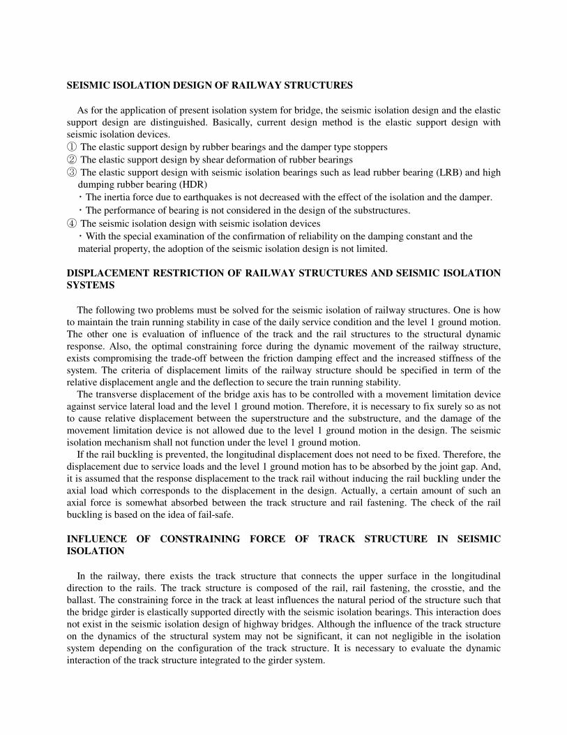
In this case, the response of the structure is evaluated by the value of the constraining force by the track. There is no problem for gradual movements like the temperature change. However, the rail and track act as a sticking mechanism against a dynamic movement like strut. The constraining force is resisted as a statically friction first, then the kinetic friction during the slip. Using a suitable frictional force, the effect of seismic isolation is enhanced due to the added damping. However, an excessive frictional force decreases the effect of seismic isolation making the natural periods of the structure shorter (Figure-1). STRONG EARTHQUAKE SIMULATOR TEST OF DYNAMIC INTERACTION OF THE TRACK-STRUCTURE SYSTEM (1) Test purpose
The dynamic behavior of the track structure exerts the influence on the frequency and the response displacement of the structure at the earthquake by the constraining force, and controls the evaluation of an accurate earthquake performance (Figure-1). Then, the experiment to verify the mechanism of the interaction caused between the track and the seismic isolation structure was carried out. However, the mechanism relates to friction and the speed dependency. And, the interaction cannot be verified by a static load test. Therefore, the test with a strong earthquake response simulator, which can generate ground motion was carried out.
(2) Strong earthquake response simulator
This test was carried out with a large-scale strong earthquake response simulator machine at Kyoto University (Figure-2).
<Specification of shaking table> Table size; 5.0m×3.0m Allowable weight; 15ton Shaking direction; 2-horizontal (X, Y), 1-vertical(Z), 3-rotation(θx, θy, θz)
Highway bridge
Seismic isolation bearing
Railway bridge
FRICTIONAL FORCE BY TRACK STRUCTURE
DIFFERENCE OF RESPONSE DISPLACEMENT
Seismic isolation bearing
Inertia force
Inertia
Inertia
Inertia force
Figure-1: Influence of Track in seismic isolation structures

Max. Stroke (mm); X:±300, Y:±250, Z:±200 Max. Velocity; X, Y, Z:±150cm/sec Max. Acc.; X, Y, Z: ±1.0G
Test model equivalent mass(15t)
①Preliminary experiment
④Only ballast without rail
②Seismic isolation-abutment
③Slide board addition
⑤Track-Structure system
Figure-4: Test method
Concrete slab
Abutment
Slide
Slide board (joint gap: 50cm) Rail Concrete
Seismic isolation device
Strong earthquake response simulator, Kyoto Univ. 3-dimensional Earthquake shaking table(5.0m×3.0m)
Rail
Abutment
Earthquake shaking table
Dynamic servo controlled actuator
Earthquake shaking table
Figure-2: Strong earthquake response simulator
Seismic isolation device
Guide rails
Slide board
Abutment Concrete slab
Sleeper Rail Ballast
Earthquake shaking table
Figure-3: Test model
Frequency region; DC~50Hz
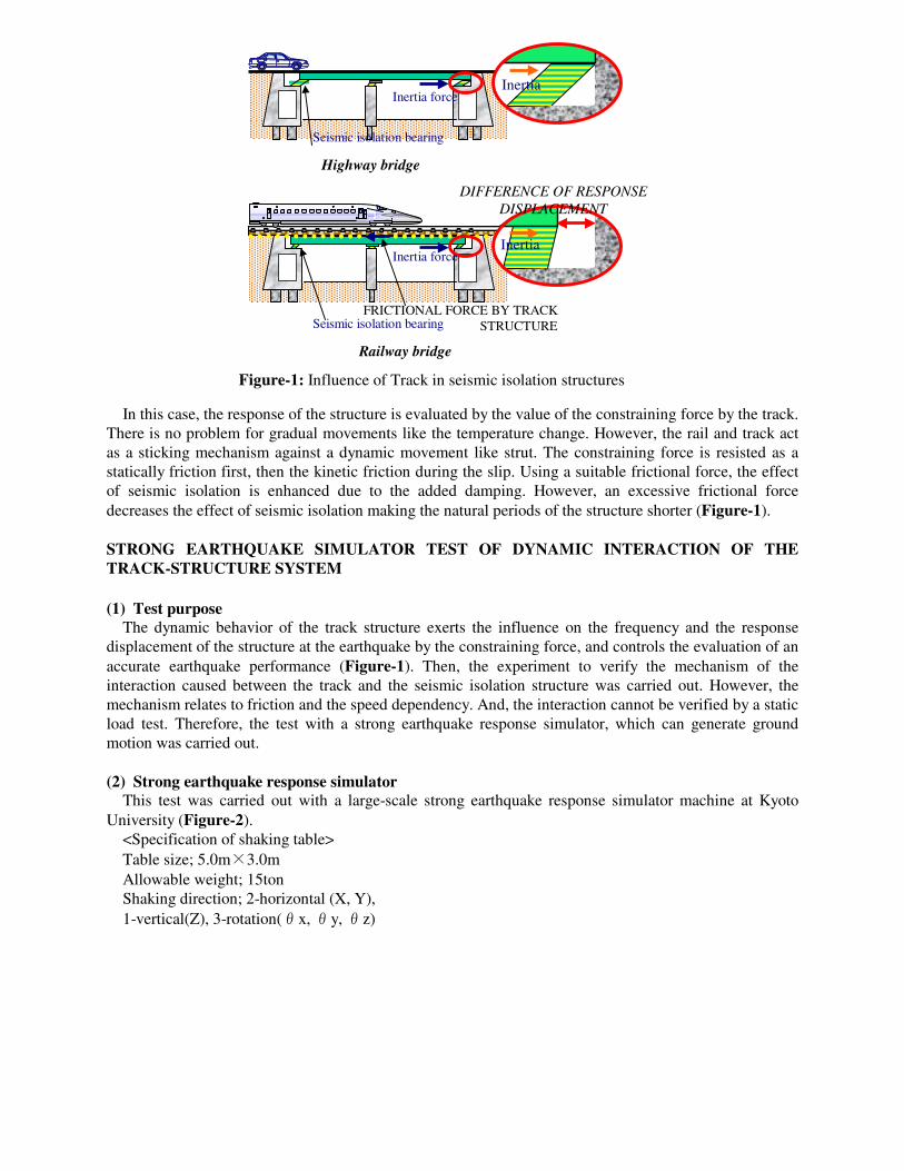
(3) Test model The experimental model consists of the edge part of the bridge girder in the seismic isolation railway
bridge, and with the adjacent abutment part. The constraining force of the track influences the relative displacement between the bridge girder and the abutment part (Figure-3).
a) Abutment part The abutment part is a steel-made and its size is1.0m in length×5.0m in width×0.55m in height, and
to achieve the same motion as the shaking table, it has high rigidity. b) Seismic isolation bridge girder
Photo.1: Strong earthquake response simulator, Kyoto Univ. and test model
-Rail free end- -Rail fixed end- -Rail spring fixed end- Photo.2: Rail of test model
Photo.3: Three kinds of springs Photo.4: Seismic isolation devices Photo.5: Displacement of the device
Spring③ Spring② Spring①

Figure-6: Ground motion acceleration waves
Max Acceleration 322gal
Level 2 ground motion (SpectrumⅠ)
Acc
eler
ati
on (
gal)
Time (sec)
Acc
ele
rati
on (
gal)
Max Acceleration 749gal
Level 2 ground motion (SpectrumⅡ)
Time (sec)
Max Acceleration 137gal
Acc
ele
rati
on
(gal)
Level 1 ground motion
Time (sec)
The bridge girder is RC slab board (nominal concrete strength: 50N/mm2) of 1.5m in length×5.0m in width×0.20m in height. It is a structure supported by one bearing and two linear guides. The natural vibration period of the model is adjusted to be 2.0 seconds which is the target natural period of usual base isolation bridges without constraining force of the track. Moreover, the joint gap with the abutment part is 50.0cm. On the joint gap, there is a steel-made slide board (t=9mm), and follows to the response displacement. The bearings are LRB and RB (LRB; Lead plugφ40,Shear modulus: G=4kgf/cm2, 180mm×180mm, h=290.7mm, Rubber thickness 6mm×30 layers, Internal steel board 2.3mm×29 piece, RB; the same size). Each has the same horizontal rigidity (7.6tf/m). Effects of the damping capability of LRB are verified by comparing the results of LRB and RB.
c) Track structure The ballast tracks are adopted, and experimented by a real-scale model and 1/2 reduction model. A real-
scale model uses the same one as the ballast track of Tokai-do Shinkansen (60kg rail track). A half model is 1/2 reductions of a real-scale (15kg rail track). The thickness of the ballast is 25cm in a real-scale model. The thickness and size distribution of the ballast of 1/2 reduction model are halves of a real-scale model. The total weight of the test model is assumed to be 15.0ton or less due to the capacity of the strong earthquake response simulator.
(4) Test method
The experiment is conducted by setting structural elements of the model one by one as shown in Figure-4. By comparing each test case, constraining force of sliding board and ballast track is detected.
(5) Test case
The total test case combining the following items in addition to the tests in Figure-4 reached 207 cases (Photograph-1-5).
Figure-5: Acceleration response spectra
10-
-2 10-
-1 10
010
110
1
102
103
10
Period
Acc
.
Damping ratio: h=5%
: Level 1 ground motion(G1) : Level 2 ground motion SpectrumⅠ(G1) : Level 2 ground motion SpectrumⅡ(G1)
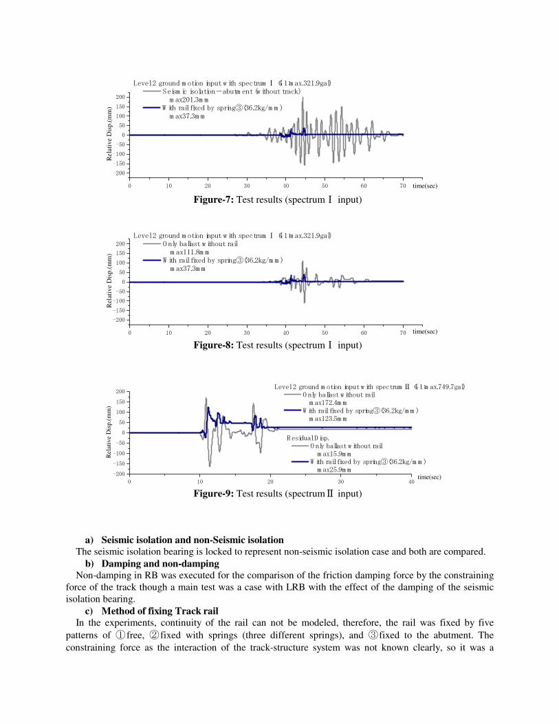
a) Seismic isolation and non-Seismic isolation The seismic isolation bearing is locked to represent non-seismic isolation case and both are compared.
b) Damping and non-damping Non-damping in RB was executed for the comparison of the friction damping force by the constraining
force of the track though a main test was a case with LRB with the effect of the damping of the seismic isolation bearing.
c) Method of fixing Track rail In the experiments, continuity of the rail can not be modeled, therefore, the rail was fixed by five
patterns of ①free, ②fixed with springs (three different springs), and ③fixed to the abutment. The constraining force as the interaction of the track-structure system was not known clearly, so it was a
0 10 20 30 40 50 60 70
-200
-150
-100
-50
0
50
100
150
200
time(sec)
Rel
ativ
e D
isp.
(mm
)
Level 2 ground m otion input w ith spectrum Ⅰ(G 1:m ax.321.9gal) Seism ic isolation-abutm ent (w ithout track) m ax201.3m m W ith rail fixed by spring③(36.2kg/m m ) m ax37.3m m
Figure-7: Test results (spectrumⅠ input)
0 10 20 30 40 50 60 70
-200
-150
-100
-50
0
50
100
150
200
time(sec)
Rel
ativ
e D
isp.
(mm
)
Level 2 ground m otion input w ith spectrum Ⅰ(G1:m ax.321.9gal) O nly ballast w ithout rail m ax111.8m m W ith rail fixed by spring③(36.2kg/m m ) m ax37.3m m
Figure-8: Test results (spectrumⅠ input)
0 10 20 30 40
-200
-150
-100
-50
0
50
100
150
200
Residual D isp. O nly ballast w ithout rail m ax15.9m m W ith rail fixed by spring③(36.2kg/m m ) m ax25.9m m
Level 2 ground m otion input w ith spectrum Ⅱ(G 1:m ax.749.7gal) O nly ballast without rail m ax172.4m m W ith rail fixed by spring③(36.2kg/m m ) m ax123.5m m
time(sec)
Rel
ativ
e D
isp.
(mm
)
Figure-9: Test results (spectrumⅡ input)
gxmxQxcxm &&&&& −=++ )(
purpose to find, which boundary conditions in the analysis has to be set. The spring constant used to fix the rail spring was spring①(149.0kg/mm) and spring②(73.4kg/mm) and spring③(36.2kg/mm). The spring① was calculated from longitudinal resistance of the ballast in normal situation. Spring② and spring③ considered the decrease rigidity of the ballast at the earthquake, decreased spring constant of spring① to the half one-quarter.
d) Loading case The seismic waves shown in Figure-4 are used in loading cases and the Sweep Test (sin wave:
Constant amplitude with frequency change) was conducted to understand frequency characteristic of the experiment model. Figure-5 shows linen response spectra level 1 ground motion, level 2 ground motion with spectrum typeⅠ, and the level 2 ground motion with spectrum typeⅡ. In the direction of the input, the bridge axis longitudinal direction, transverse direction and both-direction input were adopted1,2. ① SpectrumⅠ : The acceleration spectrum corresponding to the inter-plate type earthquakes of
magnitude 8.0 and epicenter distance of 30 to 40 kilometers. In addition, it includes ground motion due to the inland active faults, which cause an earthquake of magnitude less than 6.5.
② SpectrumⅡ: The acceleration spectrum based on the statistical analysis of the earthquake date recorded in the past inland earthquakes caused by active faults.
TEST RESULT
The main test results are shown in Figure-7, 8 and 9. Figure-7, 8 show the relative response displacement between the seismic isolation bridge girder and the abutment part with the level 2 ground motion (spectrumⅠ:max322.0gal). Figure-7 shows comparison between cases without track and with rail fixed by spring③. There is a difference of each response displacement because of the presence of the track structure. Figure-8 shows the cases only with the ballast (without rail) and the with rail fixed by spring③. The difference of each response displacement comes from the effect of the constraining force of the track structure. Figure-9 shows a case of the level 2 ground motion input with spectrumⅡ
(max749.6gal) to the same two models in Figure-8. The residual displacement of about 30mm is caused in this case. In the seismic isolation railway structure, it was confirmed that the constraining force of the track influenced the response displacement and the frequency.
MODELLING OF THE CONSTRAINING FORCE OF THE BALLAST TRACK
In this section, dynamic interaction between ballast track and isolated structures is examined based on experimental results and numerical simulations. Since bearing force could not be directly measured, nonlinear force-displacement relation of the base isolator is firstly estimated using experimentally obtained inertia force. Constraining force of the ballast track is then indirectly determined using hysteretic model of the base isolator and measured data. Validity of the estimated value is examined through numerical simulations. (1) Estimation of the bearing force
Suppose a single degree of freedom system, representing the dynamic behavior of the experimental structure with bearing but without rail structure and ballast. Equation of motion of this is as follows,
Eq.(1)
where,
m : mass of the RC slab
x&x&&
gx&&
xcxmxcxxmxQ ag &&&&&&&& −−=−+−= )()(
xcxmxcxxmFxQ ag &&&&&&&& −−=−+−=+ )()(
c : damping coefficient )(xQ : restoring force of the bearing
x : relative displacement : relative velocity
: relative acceleration : input acceleration for shake table
Restoring force character of the bearing could be then estimated as,
Eq.(2)
where, x&& a is the absolute acceleration of the base-isolated structure.
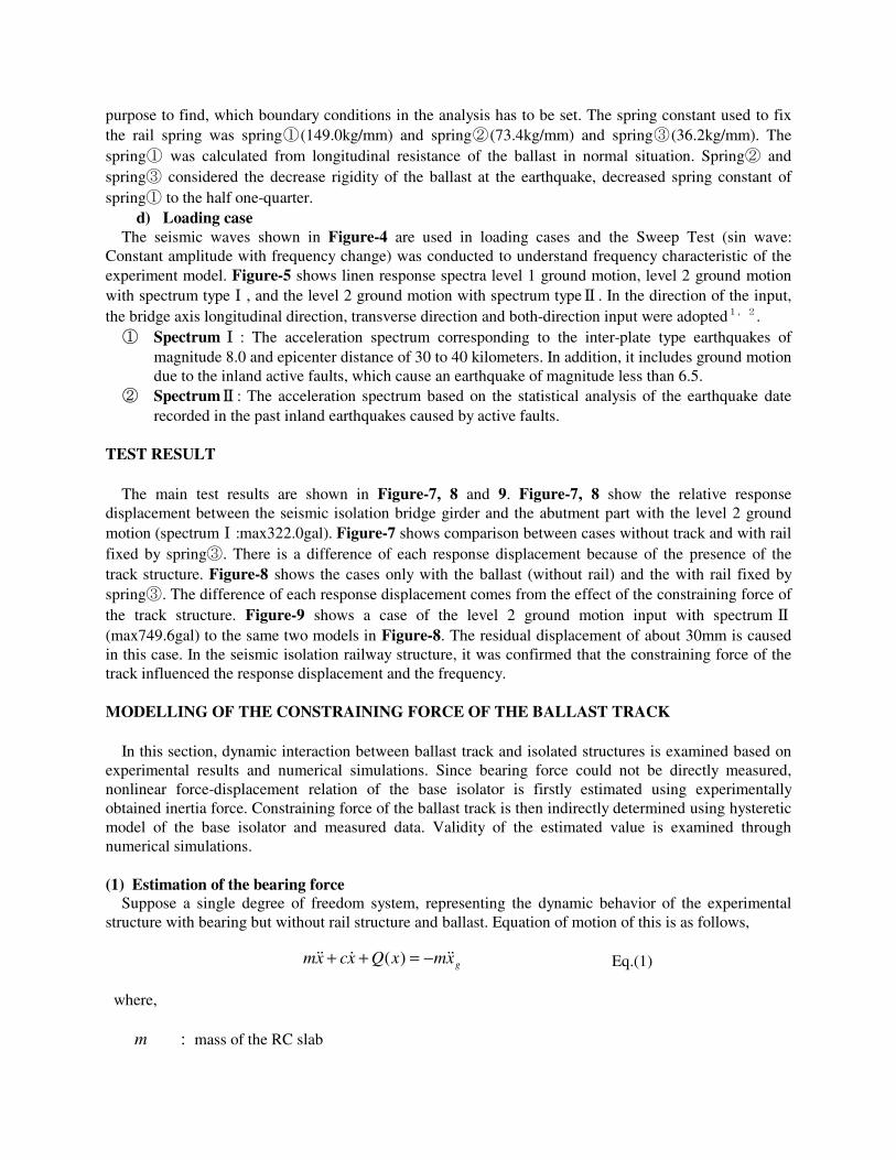
Figure-10 shows force-displacement relation of the base isolator calculated from equation (2) using
measured data of the test structure without track. Here, x&& a is the measured absolute acceleration. For relative velocity x& , integration of x&& is used. Also, 2% of damping ratio is assumed, including friction of linear guides. (2) Estimation of the constraining force of the ballast track
Considering the effect of the ballast track, equation of motion of the test structure is rewritten as follows,
Eq.(3) where,
F : constraining force of the ballast track. m : total mass of the RC slab including the ballast track stacked on the slab
In this equation, one end of the rail structure is assumed to be fixed to the abutment part, following that
constraining force of the ballast track occurs only on the base-isolated RC slab.
Figure-11 shows the hysteretic relations between total force (bearing force, Q, plus constraining force of the ballast track, F) and displacement under L2-II input motion, which are derived from real-scale experimental results with rails.
It is observed from experimental results that the existence of the constraining force of the ballast track alters the natural frequency and response of the base-isolated structure. (3) Numerical simulations of the real-scale experiments and modeling of the ballast track
constraining force In this section, constraining force of the ballast track is identified so as for the calculated response of
the assumed model to meet the experimental results. This model is primarily focused on replicating peak response and natural frequency of the base-isolated structure due to strong nonlinear character and frequency-dependency of the ballast track. Subsequently, numerical simulations are carried out using structural properties and estimated bearing force character in order to trace the experimental results and confirm the validity of the proposed model. a) Amplitude ratio of Fourier spectra
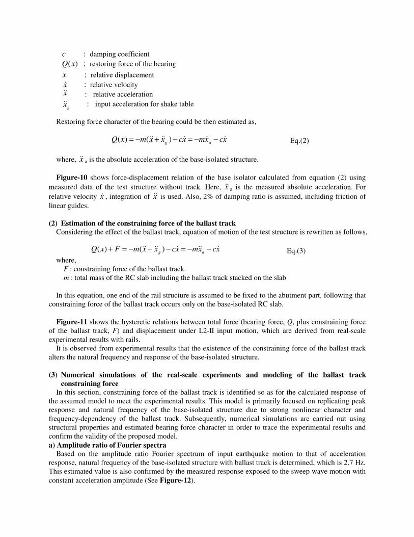
Based on the amplitude ratio Fourier spectrum of input earthquake motion to that of acceleration response, natural frequency of the base-isolated structure with ballast track is determined, which is 2.7 Hz. This estimated value is also confirmed by the measured response exposed to the sweep wave motion with constant acceleration amplitude (See Figure-12).
b) Identification of the constraining force of the ballast track In this study, nonlinear characteristic of the constraining force of the ballast track is approximated by
the Coulomb friction model, and bi-linear hysteretic model is chosen for representing the relationship between friction force and displacement. Several parameters needed for the model are determined based on experimental results. Due to strong nonlinear feature of the ballast track, following approach is primarily focused on only characterizing response at nearby resonance frequency. Natural period of the base-isolated test structure is given by,
T1=2π×8.9×k
w Eq.(4)
where,
-20 -15 -10 -5 0 5 10 15 20
Disp.(cm)
-20
-10
0
10
20
30
Forc
e(kN
)
Seismic isolation-abutment (without track ) -Level 2 ground motion input with spectrumⅠ-
Figure-10: Hysteresis curve of seismic isolation
-20 -10 0 10 20 -60
-50
-40
-30
-20
-10
0
10
20
30
40
Disp.(cm) Fo
rce(
kN)
Seismic isolation-abutment (without track ), input with L2-spectrumⅠ Rail free, input with L2-spectrumⅠ Rail fixed, input with L2-spectrumⅡ
Figure-11: Hysteresis curve of seismic isolation
0
1
2
3
0 1 2 3 4 5
Figure-12: Fourier spectrum amplitude ratio of test result
Frequency (Hz)
・Dominant frequency: 2.7Hz
Four
ier
spec
trum
am
plitu
de r
atio
Fourier spectrum amplitude ratio of relative displacement

k ::equivalent stiffness w :weight of the structure
From equation (4), equivalent stiffness of the bearing is obtained as follows,
k = ( ) wf ××× 22 28.91 π Eq.(5)
where, f is the natural frequency obtained previously. Substituting f and w yields,
k = ( ) wf ××× 22 28.91 π = ( ) 8.9/2653.127.2 22 ×× π = 37.16 (tf/m)
Given equivalent stiffness, friction force P 1 is determined as follows, P 1= uk × =37.16(tf/m)×0.0377(m)=1.401(tf)(=13.74kN/m)
where, u is the maximum relative displacement of the rail. Consequently, constraining force characteristics of the ballast track is determined as shown in Figure-
13.
(4) Numerical Simulations of the real-size experiments In order to confirm the validity of the estimated constraining force character of the ballast track,
nonlinear dynamic analysis is carried out, tracing experimental results. In these series of simulations, frame element is used to represent the behavior of the RC slab, and contributions of bearing force and ballast track are also considered (See Figure-14). Figure-15 shows comparison of relative displacements between simulation and experiment under L2-II input motion. As seen in this figure, despite overall waveforms are not consistent, good agreement is obtained with regard to the maximum displacement, which is of great importance from the viewpoints of seismic design.
One of the main reasons of this inconsistency in overall waveforms is thought to be the effect of vertical motion of the rails. In this experiment, as mentioned previously, one end of the rail structure (abutment
1.4tf/m
Figure-13: Force of constraint model of ballast track
P
δ
Figure-14: Analytical model of test
Seismic isolation device
Rail
Slide board Concrete slab
Abutment
-160
-120
-80
-40
0
40
80
120
160
0 5 10 15 20 25 30 35 40
time (sec)
Rel
ativ
e di
sp. (
mm
)
Figure-15: Analysis and test results
Test result Analysis result
part) is fixed, whereas the other side is not constrained. In this structure, if being exposed to the extreme motion, rail structures are lifted up and down instantaneously due to the liquidity and compaction effects of ballast. It consequently follows that some amount of the inertia force of the slab is transmitted to the vertical direction and horizontal inertia force is reduced, effect of which is not taken into consideration in numerical simulations. However, this effect could be negligible in case of realistic seismic designs due to the large amount of upper structure mass and prominent horizontal movements. FURTHER RESEARCH ISSUES
Three issues are currently investigated for further development.
(1) Further investigation of dynamic response of railway isolation system It is necessary to understand the train running stability and the effect of the seismic isolation
quantitatively for the reasonable seismic isolation design of railway structures, dynamics of the base-isolated structure consisting of a track the superstructure, and seismic isolation devices including the interaction between various elements (ballast, concrete slab, and directly connected track) and rail and as well as the rail fastening.
(2) Application to existing structures (seismic retrofit)
In addition to newly constructed structures, application of the isolation system to existing structures (retrofit) is an important issue. After Hyogo-ken Nanbu earthquake, the seismic retrofit of the concrete structures has been conducted. The steel jacketing and the carbon fiber wrapping method have been adopted as seismic retrofit to improve the shear strength and the ductility performance of the column. These methods are effective at the member level. On the other hand, the seismic isolation system is the most effective technique to improve earthquake performance of the total structural system (including original structure). And, the application of the seismic isolation bearing is an effective measure against the use of the steel casting bearings which received severe damage during Hyogo-ken Nanbu earthquake. This technique can be applied as a replacement work for the superannuation of bearings. It is necessary to develop the method to secure the joint gap, the seismic isolation devices for existing structures, the design criteria including the influence of surface subsoil and resonance and methods of performance validation. Additionally, the establishment of the construction method is also important. It is necessary to secure high accuracy and safety under a severe condition such as work time construction limited to the night, narrow-spaced and construction work near passing train service.
(3) Development of movement limitation device
For the level 2 earthquakes, safety is secured by UrEDAS (Urgent Earthquake Detection and Alarm System). UrEDAS is a system, which detects the primary wave of the seismic ground motion, estimates the scale of the earthquake and promptly stops high-speed trains. For the level 1 ground motion it is necessary to develop the movement limiting device for the railway isolation system for the transverse direction to assure the safety of running train. The expected performance is to prohibit the displacement at least up to the level 1 ground motion and to allow the movement under the level 2 ground motion for the effect of seismic isolation. The behavior of the device should be able to quantitatively reasonably evaluated, and the use of newly developed materials is under investigation. CONCLUSIONS
There are significant issues in the seismic isolation system of the railway structures, which are yet to be clarified including the dynamic influence of the track-structure interaction. The Research and development on these problems are ongoing for development of more rationalized seismic design methods. These Research and development are expected to contribute to the improvement of the quality and performance of the railway structures, which support safe, and high-speed mass transportation systems. In this research, experiments and simulations are carried out for introducing the economical and rational base isolation design to the railway structures.
Achievements of this research are listed as follows. 1) It is clarified that advantages of the base-isolated railway structures are, (1) reduction of
inertia force (2) improvement of the easiness and rapidness of disaster relief works, (3) improvement of seismic resistance performance of total structures including foundations, and (4) horizontal inertia force distribution.
2) Several problems unique in railway systems are introduced and examined, which should be overcame to introduce base isolation design to the railway structures. (1) displacement constraint securing running safety in daily use and under frequent
earthquake motions (Level-I) (2) evaluation of the complicated dynamics of the rail road and its effect to the railway
structure As for (1), adaptive structure is proposed which is suitable and advantageous for railway system. In the adaptive structure, displacement of the structure is constrained in daily use and under frequent Level-I motion, whereas structural system becomes base-isolated structure when being exposed to the severe earthquake. For (2), it is clarified that effect of the rail structure and ballast track should be taken intro consideration, influencing on displacement and natural frequency of the total structural system.
3) Series of real-scale shaking table tests are carried out in order to comprehend the dynamic interaction effects of the railway, ballast track, and base-isolated structure.
4) Through experimental results, it is clarified that the bi-linear friction model could trace the dynamic behavior of the ballast track.
5) Based on properties and natural frequency of the test structure, friction force level of the ballast track is estimated. Maximum displacement calculated by the numerical model of the test structure including effects of bearing and track force shows good agreement with that of measured data.
ACKNOWLEDGEMENT Authors want to express sincere gratitude to every person who supported the works in this papers.
REFERENCES 1. ' Seismic Design Code for Railway Structures ', Railway Technical Research Institute Japan (1999) 2. ' Earthquake Resistant Design Codes in Japan ', Japan Society of Civil Engineers (2000) 3. Shuji IWATA, Hirokazu IEMURA, Atsushi ICHIKAWA, Tetsuya HOSAKA and Kiyomitsu MURATA
(1999), ' Problem and View on Introduction of Isolation System in Railway Bridges ', Japan Railway Technological Union Symposium, 199-202
4. Shuji IWATA, Hirokazu IEMURA, Kazuhiko KAWASHIMA, Kiyomitsu MURATA (2000.9), ' Seismic design and seismic isolation of railway structures in Japan', Second International Workshop on Mitigation of Seismic Effects on Transportation Structures, in Taiwan 315-326

5. Hirokazu IEMURA, Shuji IWATA and Kiyomitsu MURATA (2002.9), ' Seismic Isolation of Railway Structures in Japan and Strong Earthquake Response Simulator Test ', 12th European Conference on Earthquake Engineering NO.563


![The Behavior of Multi-Story Buildings Seismically Isolated ...file.scirp.org/pdf/OJER_2014121817203398.pdf · Isolated System Hybrid Isolation ... [11]. The importance of ... -This](https://static.fdocuments.in/doc/165x107/5b348ac87f8b9a8b4b8c2651/the-behavior-of-multi-story-buildings-seismically-isolated-filescirporgpdfojer.jpg)
