Shahbaz Salaria Broadband Network Solutions TE … · Traffic/User User Density 2G Digital TDM 3G...
52
In-Building Wireless Fundamentals Shahbaz Salaria Broadband Network Solutions TE Connectivity
-
Upload
vuongtuong -
Category
Documents
-
view
216 -
download
1
Transcript of Shahbaz Salaria Broadband Network Solutions TE … · Traffic/User User Density 2G Digital TDM 3G...

In-Building Wireless Fundamentals
Shahbaz SalariaBroadband Network Solutions
TE Connectivity

Agenda
• The IBW Problem
• The IBW Solution
• DAS Introduction: Parts & Types
• Aligning DAS Type with Applications
• Q&A

What is the IBW Problem?

Traditional Macro Coverage (Challenge)

Phase 1 Microcell Placement

Phase 1 Microcell Deployment

Phase 2 iDAS Placement
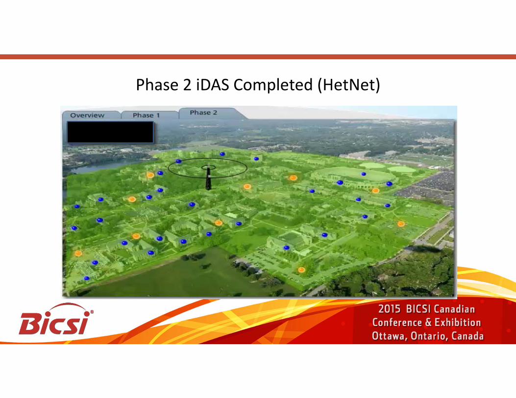
Phase 2 iDAS Completed (HetNet)

Network Evolution Addressing the Capacity Challenge
1GAnalog
AMPS
GSMUMTS/HSPA
LTE/WiMax
Cap
acit
y Li
mit
edC
over
age
Lim
ited
Larger # macro cells; Indoor coverage w/ more power;
Some micro in dense urban
Thin macro cell overlays Dense micro cell under
lays DAS for large buildings
Microcells for outdoor; DAS & Pico for
enterprise; femto for residential
Traffic/User
User Density
2G
Digital TDM
3G
Digital CDMA
4G
Digital OFDMCoverage

Market EvolutionSingle-Carrier Solutions Multi-Carrier Solutions
Wireless Carriers Enterprise
Product Need
Buyers
Narrowband BroadbandBandwidth
Yesterday Today Tomorrow

DAS Going Mainstream
Voice / Data / Video / Security / Wi-Fi / DAS
Radio Dealers/VARs Elec Contractors & Integrators
Low-voltageService
Evolution
DAS SupplierEvolution
DAS Marketplace
Yesterday Today Tomorrow

What is the IBW Solution?

The Solution
A single antenna radiating at high power (a) is replaced by group oflow-power antennae to cover the same area (b) `• Less power is wasted in overcoming penetration
and shadowing losses
• A line-of-sight channel is present more frequently– Reduced fade depths – Reduced delay spread
“An infrastructure dedicated to wireless service inside a building or structure”

The Solution-DAS
A DAS system has two main components.
• An RF source or RF front end
• A system of antennae to distribute the RF into the area that needs coverage

The Solution-DAS
A DAS system has two main components.
• An RF source or RF front end
• A system of antennas to distribute the RF into the area that needs coverage
This is what really defines a DAS, not the front end

RF Front End: Off Air
OutdoorBase
StationExpansionHub
MultimodeFiber
Twisted Pair
ExpansionHub
RF
BDA Main Hub

RF Front End: Direct BTS feed
Main HubMiniBase
Station
ExpansionHUB
Twisted Pair
Multimode Fiber
ExpansionHUB
RF
FiberMTSO

DAS Introduction

DAS Basics
The three primary types of DAS systems are:
• Passive• Semi-active or Hybrid• Active

Passive System
BDAMiniBase
Station
RF Coax ½”
RF
FiberMTSO
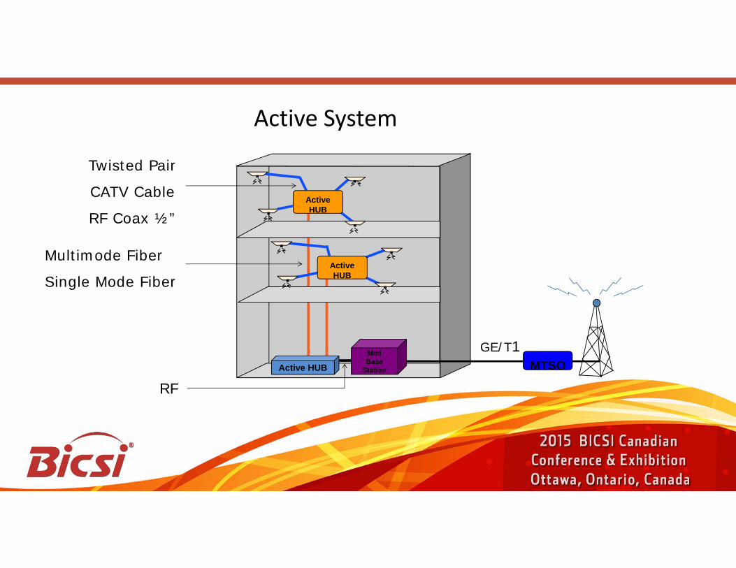
MiniBase
Station
ActiveHUB
Twisted Pair
CATV Cable
RF Coax ½”
Multimode Fiber
Single Mode Fiber
ActiveHUB
RFMTSO
GE/T1Active HUB
Active System

Aligning DAS Types withApplications

Perspectives to ConsiderChoice of DAS Solution

Perspectives for In-building DAS Design
• RF Planning
• DL Power-High• UL Noise-Low• Isolation (SNR)-High
• Installation & Management
• Cost

RF Planning Perspective
• High DL Power
• Low UL Noise
• High Isolation

RF Planning Perspective
• High DL PowerUniformly high DL power possible with PASSIVE but not for long runs
• Low UL Noise
• High Isolation

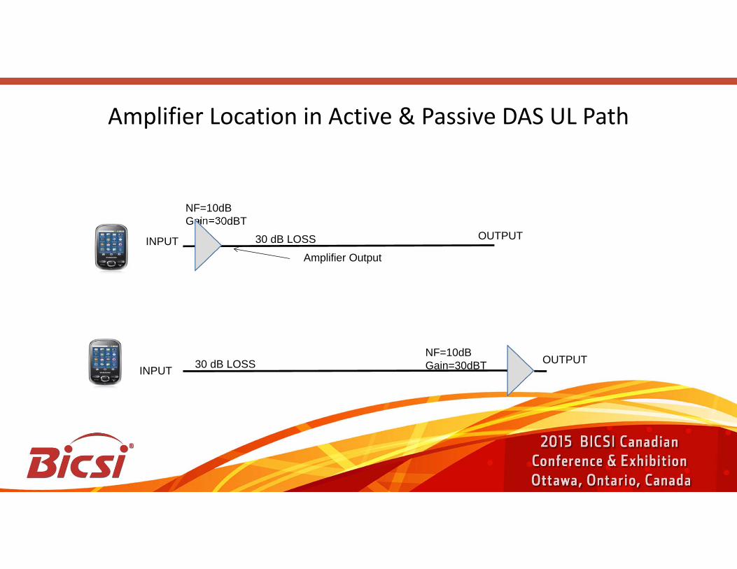
Amplifier Location in Active & Passive DAS UL Path
30 dB LOSS OUTPUTINPUT
NF=10dBGain=30dBT
Amplifier Output
30 dB LOSSINPUT
NF=10dBGain=30dBT OUTPUT
Amplifier Location in Active & Passive DAS UL Path
30 dB LOSS OUTPUTINPUT
NF=10dBGain=30dBT
Amplifier Output
30 dB LOSSINPUT
NF=10dBGain=30dBT OUTPUT

First Amplifier Close to DAS Antenna (Active)
-75 dBm
-80 dBm
-105 dBm
-120 dBm
30 dB LOSS OUTPUTINPUT
NF=10dBGain=30dBT
-85 dBm
-90 dBmS/N=45 dB
S/N=35 dB
S/N=35 dB
-45 dBAmplifier Output
-110 dBm

First Amplifier is the Base Station (Passive)
-75 dBm
-80 dBm
-105 dBm
-120 dBm
30 dB LOSSOUTPUT
INPUTNF=10dBGain=30dBT
-85 dBm
-90 dBmS/N=45 dB S/N=15 dB
S/N=5 dB
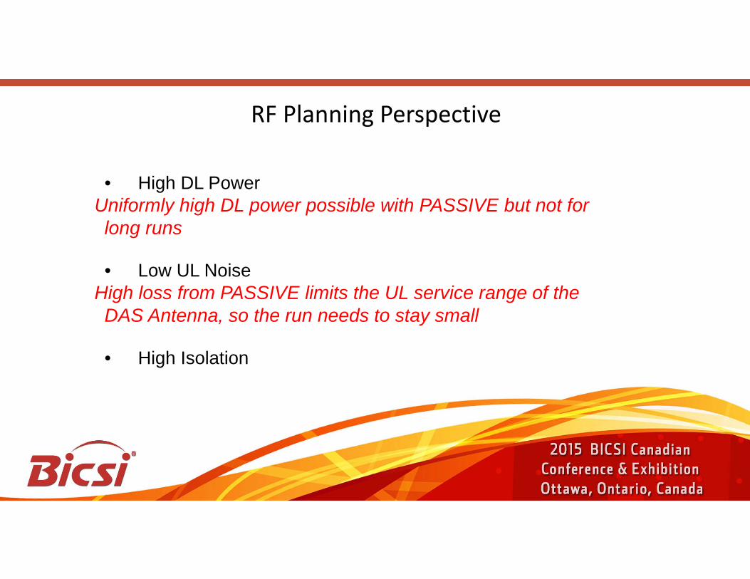
RF Planning Perspective
• High DL PowerUniformly high DL power possible with PASSIVE but not for long runs
• Low UL NoiseHigh loss from PASSIVE limits the UL service range of the DAS Antenna, so the run needs to stay small
• High Isolation

RF Planning Perspective
• High DL PowerUniformly high DL power possible with PASSIVE but not for long runs
• Low UL NoiseHigh loss from PASSIVE limits the UL service range of the DAS Antenna, so the run needs to stay small
• High IsolationNon uniform nature of PASSIVE DAS limits the isolation capability to small cable run systems

High Isolation- A Challenge of RF performance
Isolation, interference•Users receive signals from many base stations
This is interference
•Metallic coated windows attenuate the signal•The result is
Degraded / no serviceDropped calls
•The solution is to have a dominant signal

Installation & Management Perspective
• Passive better suited to harsh environments
• Difficult and costly to install
• Does not support remote monitoring, diagnostics and control
• Poor adaptability to network changes

Cost Perspective
• Passive is almost always the cheapest option from an equipment standpoint
• Largest cost element for PASSIVE is in installation which limits suitability of PASSIVE to small systems only
• Non-recoverable investment
• High installation cost of future changes/upgrades

Passive DAS: Traditional Coax
Specific challenges using the traditional design
•Large footprint for base station, typical 3 x 19”
rack per operator
•Need dedicated room
•High Thermal and Power load (10-20kW)
•Load of cable installation
•High impact installation
Typical High Power base station, one operator
Traditional coax installation

Criteria Guidance for Choice of DAS• Venue Size
• Cost Constraints
• Long Term• Short Term
• Flexibility Objectives
• Maintenance Considerations
• Age of the Venue & Type of Construction

In Building VenuesThree Main Size Segments
Large Venue Medium/Small VenueLarge/Medium Venue
Large Venue• Sports Venues• Convention Centre• Large Mall• Outdoor• Ultra High Rise• Large Campus
Medium/Small VenueLarge/Medium Venue
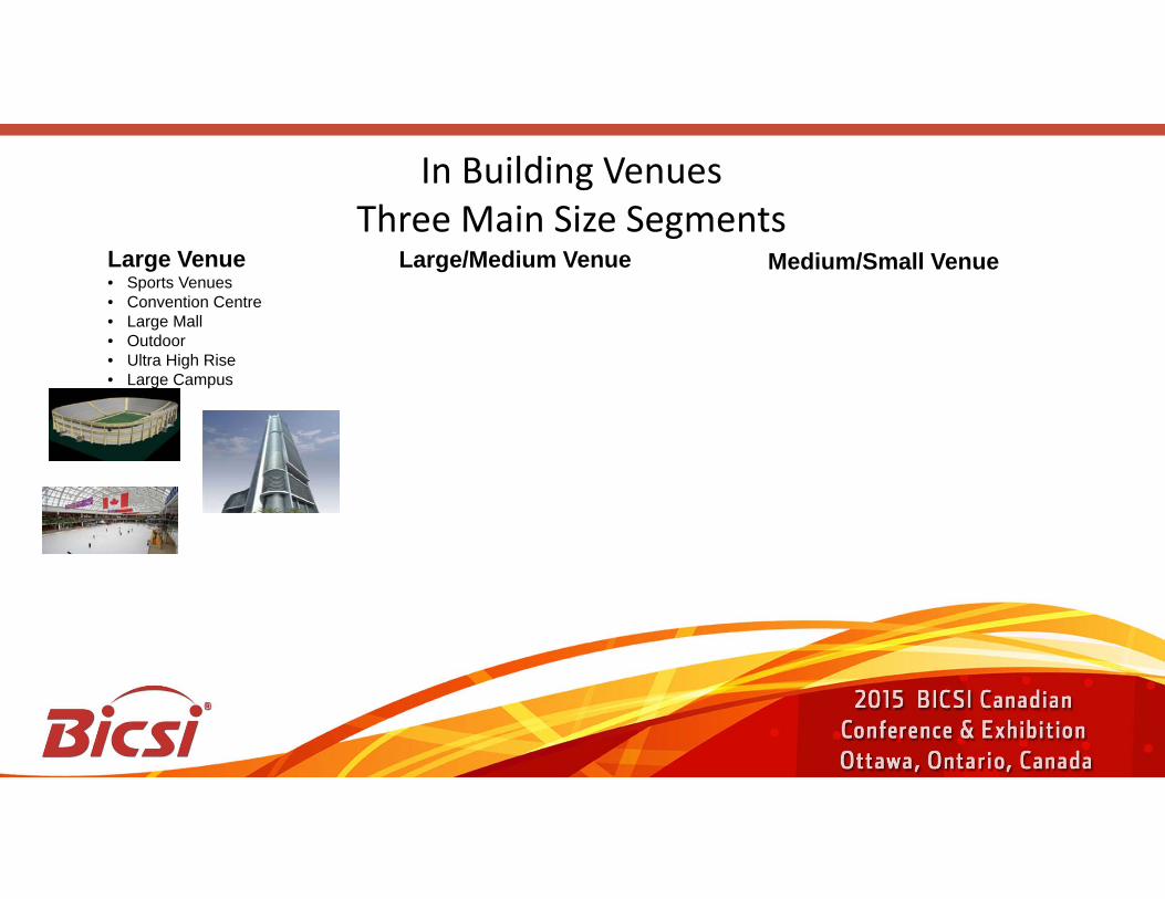
In Building VenuesThree Main Size Segments

Large Venue• Sports Venues• Convention Centre• Large Mall• Outdoor• Ultra High Rise• Large Campus
Large/Medium Venue• Hospital• Hotel• University• High Rise• Warehouse• Office Building
In Building VenuesThree Main Size Segments
Medium/Small Venue

Large Venue• Sports Venues• Convention Centre• Large Mall• Outdoor• Ultra High Rise• Large Campus
Medium/Small Venue• Small Business• Rural Store• Local Library
Large/Medium Venue• Hospital• Hotel• University• High Rise• Warehouse• Office Building
In Building VenuesThree Main Size Segments

In-Building DAS MarketThree Main Segments by Size/Category
Large Venue• Sports Venues• Convention Centre• Large Mall• Outdoor• Ultra High Rise• Large Campus
Medium/Small Venue• Small Business• Rural Store• Local Library
Large/Medium Venue• Hospital• Hotel• University• High Rise• Warehouse• Office Building
Active Suited Moving towards Active Passive Suited
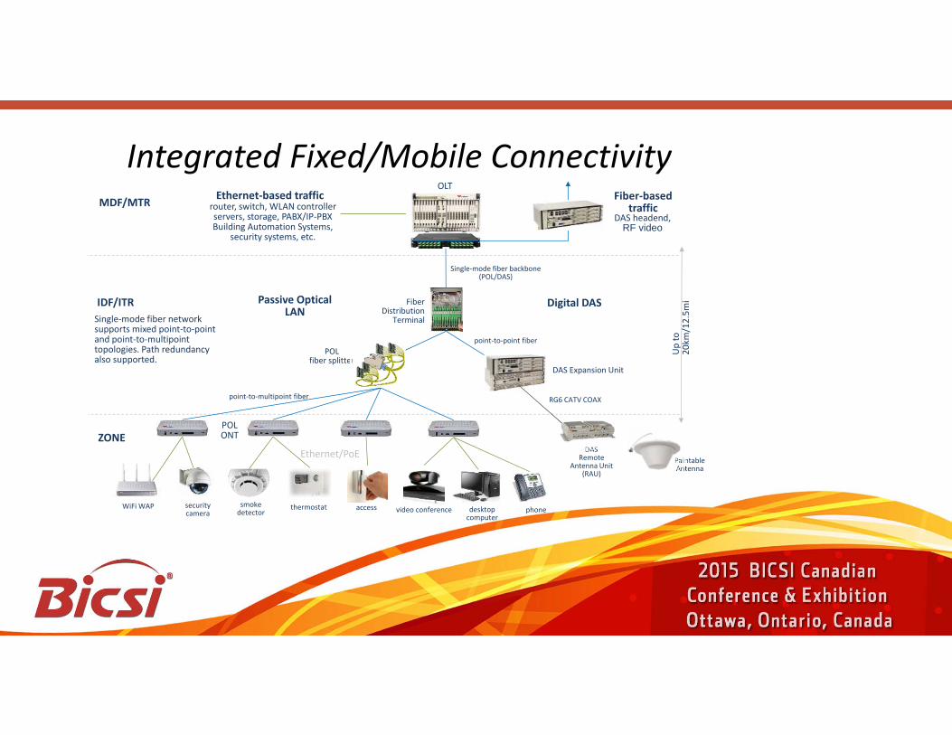
Integrated Fixed/Mobile Connectivity
DAS Remote
Antenna Unit(RAU)
WiFi WAP security camera
smoke detector
thermostat access video conference desktop computer
phone
Ethernet/PoE
POL ONT
point-to-point fiber
OLT
router, switch, WLAN controllerservers, storage, PABX/IP-PBXBuilding Automation Systems,
security systems, etc.
Single-mode fiber network supports mixed point-to-point and point-to-multipoint topologies. Path redundancy also supported.
Ethernet-based traffic Fiber-based traffic
DAS headend, RF video
Fiber Distribution
Terminal
MDF/MTR
Passive Optical LAN
point-to-multipoint fiber
POL fiber splitter
Up
to
20km
/12.
5mi
DAS Expansion Unit
Single-mode fiber backbone (POL/DAS)
RG6 CATV COAX
IDF/ITR Digital DAS
Paintable Antenna
ZONE

What is Next?Fusion of SBS and DAS

Melting of Point of Interface
DAS-SBS POI
SBS POIDAS Hub
ANT
Optical
RF
RF Analog Interface
Optical Digital Interface (CPRI)
DAS Remote

Melting of Point of Interface
DAS-SBS POI
SBS POIDAS Hub
ANT
Optical
RF
Heavy demand on space, power & cooling systems
RF Analog Interface
Optical Digital Interface (CPRI)
DAS Remote

Melting of Point of Interface
DAS-SBS POI
SBS POIDAS Hub
ANT
Optical
RF
Heavy demand on space, power & cooling systems
Optical Digital Interface (CPRI)
Optical Digital Interface (CPRI)
DAS Remote

Melting of Point of Interface
SBS DAS Hub
ANT
Optical
RF
Optical Digital Interface (CPRI)
Optical Digital Interface (CPRI)
DAS Remote

Melting of Point of Interface
DAS CPRI Hub
DAS Remote
ANT
Optical
RF
Optical Digital Interface (CPRI)
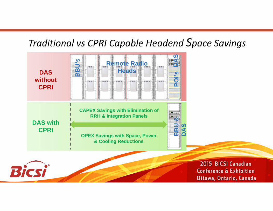
Traditional vs CPRI Capable Headend Space Savings
DAS without
CPRIB
BU
’s Remote Radio Heads
POI’s
DA
S
DAS with CPRI
CAPEX Savings with Elimination of RRH & Integration Panels
OPEX Savings with Space, Power & Cooling Reductions
BB
U &
D
AS

30% CAPEX Eliminate RRH & Integration Panels
50% OPEX Space, Power & Cooling Reductions
CPRI Interface on DAS – Cost Savings

Thank You !!!