SHAFT MOUNTED HELICAL GEAR REDUCER - · PDF fileINTRODUCTION FEATURES The VIGNESSH Shaft...
12
SHAFT MOUNTED HELICAL GEAR REDUCER
-
Upload
nguyendien -
Category
Documents
-
view
221 -
download
2
Transcript of SHAFT MOUNTED HELICAL GEAR REDUCER - · PDF fileINTRODUCTION FEATURES The VIGNESSH Shaft...

SHAFT MOUNTED HELICAL GEAR REDUCER

Shaft Mounted Helical Gear Assembly

INTRODUCTION
FEATURES
The VIGNESSH Shaft Mounted Helical Gear Units are the result of experience in design and production, taking advantage of the
most recent relevent research in the field of gearing technology.
Q Mounts direct onto the driven shaft.
Q No alignment problems & No shaft couplings.
Q The standard torque arm provided generally restricts any torque reaction and gives access for easy adjustment of 'V' belt
from motor pulley.
Q Output speeds 10 to 300 rpm.
Q Power rating upto 113 kW
Q Gear unit sizes C,D,E,F,G,H & J with nominal gear ratios of 5:1, 13:1, 20:1 & 25:1
Gears
Helical gears are made out of Nickel, Chrome and Molybdenum, case hardening alloy steel. This profile ground
gears ensures high standards of accuracy to relevant ISO/DIN standards to achieve quite running characteristics.
Output hollow shaft
The output hollow shaft with a keyway in the inner bore is made of high grade steel to transmit the
required torque.
Gear casing
The casings are designed to have the optimum strengh and give rigid support to the bearings and the running
gears. They are made of close grained Cast Iron to have high strength and vibration damping properties.
Bearings
The anti friction deep groove ball bearings of reputed make used to have longer life and support the pinion
shafts and the output hollow shaft.
Lubrication
A positive lubrication system ensures a continous flow of oil on to the gears and the bearings. Oil filler/breather,
oil level indicator, and drain plugs are provided in proper locations for easy maintenance. Efficient oil seals are
provided to prevent any oil leak.
Backstops
A simple accessory prevents reversal of the Speed reducer and is ideal for inclined conveyors.
It is important that the backstop is installed correctly to ensure a safe operation.
1
SHAFT MOUNTED HELICAL GEAR REDUCER
SHAFT MOUNTED HELICAL GEAR REDUCER

Selection procedure
1. Determine required output speed & absorbed power by the
driven machine.
Absorbed Power(Kw) = Absorbed Torque(Nm)xMachine Speed(rpm)
9550
2. If the torque is not known take the Absorbed Power as the driven
motor power itself.
3. Determine the service factor from table 'I’
4. Multiply the absorbed power by the service factor to arrive at the
Mechanical power capacity (Pn)
5. Using the table 'III,IV & V' select the smallest gear unit that is
capable of transmitting the power Pn.
Example:
To select a shaft mounted helical gear unit to drive a
uniformly feed conveyor having a torque requirement of 660
Nm and to be run at 72 rpm and the connected electrical
motor is 5kW / 1440 rpm. The working cycle is 7X24.
Absorbed Power=660 X 72/9550=4.98 kW
service factor from the table 'I'=2.0
Mechanical Power Capacity (Pn) = 4.98 x 2.0 = 9.96 kW
From the table 'V' we find that size 'G' can be selected
with 20:1 as reduction ratio and the output speed will be
72 rpm and the Rated Power of the gear unit will be 20 kW
SMHG G 20
Type
Shaft Mounted Helical Gear Reducer
Size :
C, D, E, F,
G, H or J
Reduction Ratio:
5:1, 13:1, 20:1 or 25:1
SERVICE FACTOR Table I
Uniform Load
Moderate Shock
Heavy shock
Driven Machine TypeOperating Hours Per Day
<10 Hrs 10-16 Hrs >16 Hrs
Agitators and Mixers-liquid or semi-liquid Blowers-centrifugal Bottling Machines, Conveyors and
Elevators-uniformly loaded Cookers, Laundry Washing Machines,non reversing Line shafts,
Pumps-Centrifugal and gear, Wire Drawing Machines
Agitators and Mixers-Variable density Conveyors -non uniformly loaded, Cranes travel, motion and
hoisting, Kilns Laundry Tumblers,lifts,Piston Pumps - with 3 or more cylinders, Pulp and Paper
Making Machinery, Rubber Mixers and Calenders, Rotary Screens,Textile Machinery
Brick Presses, Briquetting Machines, Conveyors-reciprocating and shaker, Crushers,
Feeders-reciprocating, Hammer Mills, Piston Pumps-1 or 2 cylinders, Rubber Masticators,
Vibrating Machines.
1.0 1.12 1.25
1.25 1.4 1.6
1.6 1.8 2.0
LUBRICANTS & MOUNTING POSITION
USE OIL OF GRADE ISO VG 320 Like
b - breather l - oil level indicator d - drain
NOMENCLATURE
Details required in orders
Type
Size
Reduction Ratio
Example :
Shaft Mounted Helical Gear Reducer of Size G & having a
Reduction Ratio of 20:1, Type SMHG G20
The Shaft Mounted Gearbox is delivered after draining the oil used while testing. It should be filled with proper grade oil to the correct level, as in
the oil level indicator. To the various possible positions of the gearbox, the locations of drain plug, oil filler/breather and oil level indicator are
shown in the sketch below.
Indian Oil -
Hindustan Petroleum - Parthan-EP 320
Bharat Petroleum - BharatAmocam-320
Castrol - Alpha SP-320
Caution :- Too much oil will cause over heating and too
less oil will cause gear failure.
Servomesh-SP 320
2
SHAFT MOUNTED HELICAL GEAR REDUCER
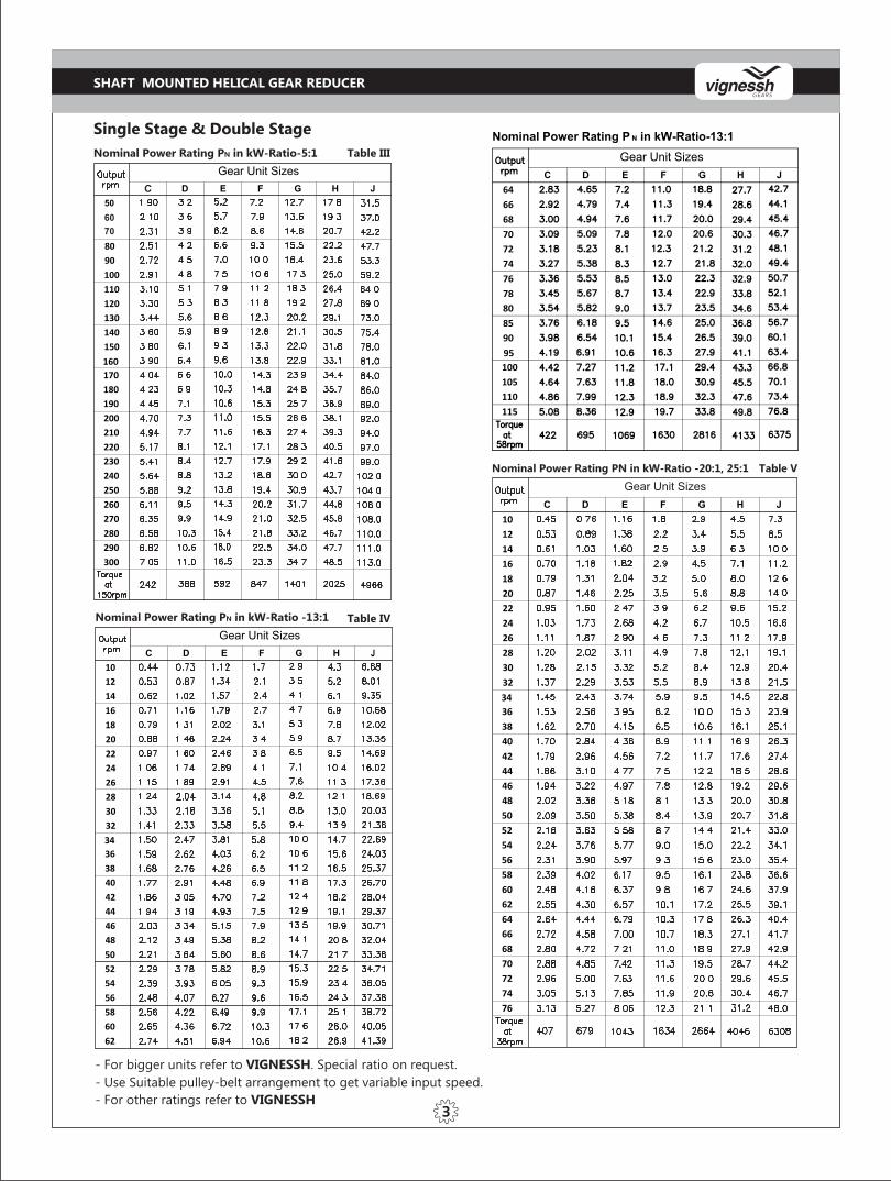
- For bigger units refer to VIGNESSH. Special ratio on request.
- Use Suitable pulley-belt arrangement to get variable input speed.
Nominal Power Rating PN in kW-Ratio-5:1 Table III
Table IVNominal Power Rating PN in kW-Ratio -13:1
Table VNominal Power Rating PN in kW-Ratio -20:1, 25:1
Single Stage & Double Stage
3- For other ratings refer to VIGNESSH
60
70
SHAFT MOUNTED HELICAL GEAR REDUCER
C
Gear Unit Sizes
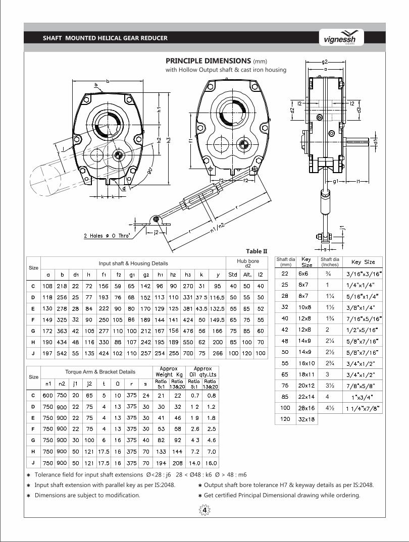
PRINCIPLE DIMENSIONS (mm)
with Hollow Output shaft & cast iron housing
Table II
Q Tolerance field for input shaft extensions Ø<28 : j6 28 < Ø48 : k6 Ø > 48 : m6
Q Input shaft extension with parallel key as per IS:2048. Q Output shaft bore tolerance H7 & keyway details as per IS:2048.
Q Dimensions are subject to modification. Q Get certified Principal Dimensional drawing while ordering.
4
SHAFT MOUNTED HELICAL GEAR REDUCER
Input shaft & Housing Details Hub bore Shaft dia(mm)
Shaft dia(Inches)
Torque Arm & Bracket Details
¾
1
1¼
1½
1¾
2
2¼
2½
2¾
3
3½
4
4½

TORQUE ARM
SECTIONAL ASSEMBLY
Single Stage, Ratio - 5:1
5
While ordering parts for a Reducer,
specify reducer size, ratio, serial number,
part name and part number along with
qty. required
SHAFT MOUNTED HELICAL GEAR REDUCER

While ordering parts for a Reducer, specify reducer size, ratio, serial number, part name and
part number along with qty. required
TORQUE ARM
SECTIONAL ASSEMBLY
Double Stage, Ratio -13, 20:1 & 25:1
6
SHAFT MOUNTED HELICAL GEAR REDUCER

SIZE C
Q Check the direction of shaft rotation required.
Q Ensure 'O' rings end are fully engaged in their respective grooves.
Q With the backstop race fitted in the correct direction into the outer race, Push the assembly into the housing, rotating the
shaft in its free direction will assist.
Q Secure the complete assembly using the screws provided.
Q Finally, after checking for correct shaft rotation, fit the sealing cap into the outer race.
Q Fill the reducer with correct grade of oil VG 320.
Q The assembly may be tapped gently if necessary. To change the backstopping direction at any time, it is necessary to
remove the sprag assembly and turn it end for end.
SIZES D - J
Q Remove Backstop cover, check the direction of shaft rotation required.
Q Ensure 'O' rings on both end are fully engaged in their respective grooves.
Q With the backstop race fitted in the correct direction into the outer race, Push the assembly into the housing, rotating the
shaft in its free direction will assist.
Q When the outer race is fully inserted, rotate the shaft in its backstopping direction. If the assembly is correct, the outer
race will now rotate with the shaft. Use this feature to align the screw holes. Place the backstop cover onto the
projecting outer race spigot and secure the complete assembly using the screws provided.
Q Fill the reducer with correct grade of oil VG 320.
Q The assembly may be tapped gently if necessary. To change the backstopping direction at any time, it is necessary to
remove the sprag assembly and turn it end for end.
TO INSTALL BACKSTOP
7
SPRAG ASSEMBLY
SPRAG ASSEMBLY
SHAFT MOUNTED HELICAL GEAR REDUCER

1. Install pulley on input shaft as close to the gear box as
possible. Fails to do this will cause excess loads in the input
shaft bearings and could cause their premature failure.
2. The V-Belt drive may be located in any convenient
position. If the toque-arm is to be used to tighten the
belts, the drive should be at above 90° to line between
the input and output shafts.
3. If output hub runs anti-clockwise the torque arm should
be positioned to the right as shown in the fig.
If output hub runs clockwise, position Belt drive and
torque arm in opposite direction to that shown in the fig.
Install torque-arm bracket on a rigid support so that the
torque-arm will be at approximately right angles to the
centre line through the driven shaft & the torque-arm
case bolt.
4. Make sure there is sufficient take-up in the torque-arm
nut for belt tension adjustment.
Angle (a) should be a right angle but may vary upto a
maximum of 15° either way.
Important aspects of belt and torque-arm installation:-
8
SHAFT MOUNTED HELICAL GEAR REDUCER

Bevel Helical Gear Box
Vertical Adaptable VAU
Helical Spares Worm & Worm Wheel Screw JackBevel Spares
Geared Motor
Helical Gear Box Under Driven
OTHER PRODUCTS
Bevel Gear Box
Double Reduction
Helical Extruder

WORM GEAR BOXES UPTO 12” CENTER DISTANCE
HELICAL GEAR BOXES
BEVEL HELICAL GEAR BOXES
CUSTOM BUILT GEAR BOXES
EXTRUDER GEAR BOXES
SCREW JACK UPTO 50 TONNE
GEARED MOTOR UPTO 50 HP
SHAFT MOUNTED HELICAL GEAR REDUCER
WORM & WORM WHEEL PAIRS
HARDENED & GROUND GEARS
Vignessh Gears Private LimitedNo. 55, Mahathma Gandhi Road,
SIHS Colony,
Coimbatore – 641 033. Phone : 0422 - 2270349
: 0422 - 2271200.
Mobile : 095004 91110
: 097900 39990
E-mail : [email protected]
Web : www.vignesshgears.com