Shaft boring systems for mechanical excavation of deep shafts
21
AUSTRALIAN CENTRE FOR GEOMECHANICS Volume No. 34 May 2010 NEWSLETTER The views expressed in this newsletter are those of the authors and may not necessarily reflect those of the Australian Centre for Geomechanics. Continued page 2 IN THIS EDITION • Shaft boring systems, Page 1 • Strategic block caving, Page 5 • Caving 2010 symposium, Page 8 • Seal blistering at Lake Grace, Page 10 • Slopes and saprolites, Page 12 • ACG news, Page 19 • ACG event schedule, Page 20 www.minewaste2010.com 29 September – 1 October 2010, Perth, Western Australia Early bird registration expires 16 August 2010 Mine Waste 2010 will tackle the full range of issues that constitute risks in the management of mining wastes, particularly tailings and waste risk. This forum will encourage debate amongst practitioners, researchers and regulators about the key shortcomings in industry’s current understanding of the performance of mining waste storage facilities and associated risks faced by owners and operators of these facilities. More than 70 abstracts were accepted. First International Seminar on the Reduction of Risk in the Management of Tailings and Mine Waste Shaft boring systems for mechanical excavation of deep shafts For excavation of declines, tunnel boring machines (TBM) can be used in many cases. These provide, in certain rock conditions, considerably higher production rates compared to drill and blast excavation. Herrenknecht AG has developed a vertical shaft sinking machine (VSM) that allows excavating shallow shafts in soil and medium soft rock. The ground is excavated by a roadheader boom. The muck is removed by a slurry system or a pneumatic system in combination with hoisting of skips. These machines have been applied successfully on shafts down to 100 m. Recently, a pre-sink for a deep mine shaft has been excavated by this technology. Introduction For the development of block caving mines fast access to the orebody is critical. In some cases the mineralised area is more than 1,500 m below surface. Excavation of shafts or declines is typically a critical path of the project schedule. Saving time on these activities can significantly increase the net present value of the mining project. Mechanical excavation methods are a step- change in excavation performance and labour safety compared to drill and blast operations. In hard rock conditions, roadheaders cannot be used effectively, so disc cutting is the first choice. by Christian Frenzel and Werner Burger, Herrenknecht AG, Germany, and Fred Delabbio, Rio Tinto, Australia
Transcript of Shaft boring systems for mechanical excavation of deep shafts

A U S T R A L I A N C E N T R E F O R G E O M E C H A N I C S V o l u m e N o . 3 4 M a y 2 0 1 0
NEWSLETTER
The views expressed in this newsletter are those of the authors and may not necessarily reflect those of the Australian Centre for Geomechanics.
Continued page 2
IN THIS EDITION • Shaft boring systems, Page 1• Strategic block caving, Page 5• Caving 2010 symposium, Page 8• Seal blistering at Lake Grace, Page 10• Slopes and saprolites, Page 12• ACG news, Page 19• ACG event schedule, Page 20
www.minewaste2010.com
29 September – 1 October 2010, Perth, Western Australia
Early bird registration expires 16 August 2010
Mine Waste 2010 will tackle the full range of issues that constitute risks in the management of mining wastes, particularly tailings and waste risk. This forum will encourage debate amongst practitioners, researchers and regulators about the key shortcomings in industry’s current understanding of the performance of mining waste storage facilities and associated risks faced by owners and operators of these facilities. More than 70 abstracts were accepted.
First International Seminar on the Reduction of Risk in the
Management of Tailings and Mine Waste Shaft boring systems for
mechanical excavation of deep shafts
For excavation of declines, tunnel boring machines (TBM) can be used in many cases. These provide, in certain rock conditions, considerably higher production rates compared to drill and blast excavation.
Herrenknecht AG has developed a vertical shaft sinking machine (VSM) that allows excavating shallow shafts in soil and medium soft rock. The ground is excavated by a roadheader boom. The muck is removed by a slurry system or a pneumatic system in combination with hoisting of skips. These machines have been applied successfully on shafts down to 100 m. Recently, a pre-sink for a deep mine shaft has been excavated by this technology.
Introduction
For the development of block caving mines fast access to the orebody is critical. In some cases the mineralised area is more than 1,500 m below surface. Excavation of shafts or declines is typically a critical path of the project schedule. Saving time on these activities can significantly increase the net present value of the mining project.
Mechanical excavation methods are a step-change in excavation performance and labour safety compared to drill and blast operations. In hard rock conditions, roadheaders cannot be used effectively, so disc cutting is the first choice.
by Christian Frenzel and Werner Burger, Herrenknecht AG, Germany, and Fred Delabbio, Rio Tinto, Australia

2 Australian Centre for Geomechanics • May 2010 Newsletter
© Copyright 2010. Australian Centre for Geomechanics (ACG), The University of Western Australia (UWA). All rights reserved. No part of this newsletter may be reproduced, stored or transmitted in any form without the prior written permission of the Australian Centre for Geomechanics, The University of Western Australia.
The information contained in this newsletter is for general educational and informative purposes only. Except to the extent required by law, UWA and the ACG make no representations or warranties express or implied as to the accuracy, reliability or completeness of the information contained therein. To the extent permitted by law, UWA and the ACG exclude all liability for loss or damage of any kind at all (including indirect or consequential loss or damage) arising from the information in this newsletter or use of such information. You acknowledge that the information provided in this newsletter is to assist you with undertaking your own enquiries and analyses and that you should seek independent professional advice before acting in reliance on the information contained therein.
For deep hard rock shafts, a new shaft boring system (SBS) has been developed by Herrenknecht AG in collaboration with Rio Tinto. Based on proven technologies, the system utilises a unique arrangement of existing technologies. The system integrates excavation, mucking, primary rock support, installation of the final lining, and shaft infrastructure. This new system dramatically improves the health and safety of shaft construction. Detailed performance estimates indicate significantly higher shaft construction rates are possible compared to conventional shaft sinking methods.
Mechanical excavation
One of the options to increase overall mine performance is mechanised excavation, mainly because more process steps can take place simultaneously, e.g. excavation and muck removal. In some cases, the installation of rock support can be performed simultaneously.
Two main types of mechanical excavation tools are used:• cutter bits (or picks)• disc cutters.
Cutter bits act with high impact loads under a low angle to the rock surface, while disc cutters typically operate by rolling over the surface and penetrating the rock in a perpendicular direction.
It should be noted that the advantages of cutter bits are lower cutting forces and more flexible cutting kinematics that lead to comparably small and lightweight equipment suitable for a more flexible excavation geometry.
Once the rock strength exceeds the range of 100–120 MPa unconfined compressive strength, rock excavation with cutter bits becomes increasingly infeasible due to low penetration rates and high bit consumption. Disc cutters are able to excavate rock with a compressive strength of more than 300 MPa, but require significantly higher cutting forces which lead to heavier and less mobile equipment. To achieve high excavation rates, disc cutters are usually employed on rotary full-face TBM.
Vertical shaft machine
The VSM has been developed for the mechanised excavation of shallow shafts in water-bearing soils (Suhm, 2006). This technology is based on a roadheader boom with a cutter drum equipped with cutter bits or soft ground chisels. A typical setup is shown in Figure 1.
The roadheader boom is attached to a mainframe which can be equipped with gripper pads to stabilise and support the machine. The whole machine is designed to operate in submerged conditions; remotely controlled from the surface.
Two options are available for rock support:• pre-cast concrete segments (segmental
lining)• rockbolts, wire mesh, and sprayed
concrete.The segments are erected on the surface
and the whole lining is lowered as the shaft is sunk — the usual option for soft ground conditions. In stable to poor soft rock conditions, rockbolting, installation of wire mesh and shotcreting can be performed from special designed working platforms with permanently installed rockdrills and shotcreting equipment (Figure 2).
Figure 1 Core component of vertical shaft machine
VSM technology has been used on a number of projects in soil and soft rock conditions with rock strengths of up to 120 MPa. As a conveying system, a slurry circuit is used for soft soil below ground water level and a pilot hole for dry conditions.
Up to now this method has been used predominantly in civil construction such as deep shafts for sewage tunnels. Currently, a VSM rig is used to excavate the pre-sink for a deep mine shaft. VSM technology is used to substitute the usual solutions of consolidation by grouting or ground-freezing methods, as well as the use of the slurry wall method. The VSM method can save valuable time and decrease risks associated with ground cementation, ground-freezing shaft sinking methods or increased alignment difficulties for very deep slurry wall shafts.
A vacuum suction system with exchangeable skips is in development which will enable the VSM system to excavate blind shafts to depths greater than 100 m. In addition, alternative partial face cutting systems are under evaluation to increase the maximum rock strength that can be excavated.
Shaft boring system
The SBS is a development for the mechanised excavation of deep vertical blind shafts in hard rock conditions. The semi full-face sequential excavation process
Figure 2 Work stage of VSM for installation of rock support

3Australian Centre for Geomechanics • May 2010 Newsletter
Undergroundis based on the use of a rotating cutting wheel excavating the full shaft diameter in a two stage process for one complete stroke. An overview of the system is shown in Figure 3.
The excavation process is divided into two steps:• trench excavation to a depth of one
stroke with the cutting wheel rotating around its horizontal axis and being pushed downward in the shaft direction
• excavation of the entire bench (face) area by slewing the rotating cutting wheel 180° around the shaft vertical axis. The SBS machinery consists of three
major areas of equipment and operation which are (starting from the bottom):• shaft boring machine with excavation,
muck transport and gripping system as well as equipment for primary rock support and probe drilling
• primary platform decks for SBS supply infrastructure and power packs
• secondary platform decks for final lining installation, muck handling and services extension.The SBS machine can be separated into
the main functional areas (starting from the bottom):• excavation chamber with cutting wheel,
cutting wheel drive assembly, mechanical machine support structure, shotcrete and probe drilling equipment (Figure 3(1))
• adjustable front support with slew bearing/drive assembly cutting wheel support and dust shield (Figure 3(2))
• regular rock support area for rockbolts (Figure 3(3))
• SBS mainframe with gripper carrier, gripper system and thrust cylinders (Figure 3(4))
• rear alignment system (secondary gripper)
• muck handling system (Figure 3(5)).The cutting wheel circumference and
periphery of both sides are equipped with appropriate cutting tools and muck buckets to excavate the rock and remove the cuttings while rotating. Excavation and muck removal is a continuous process. The cuttings are guided along internal muck channels and discharged by gravity onto a centre arranged secondary conveying system.
All reaction forces of the excavation process are transferred into the shaft walls by grippers arranged in the rear. During the gripper reset operation after each excavation cycle, the machine can be adjusted along its vertical axis for alignment control.
Figure 3 Overview of the SBS
A full mining cycle consists of the following steps, once the SBS is reset:• trench excavation (plunging)• bench excavation (slewing)• extend SBS support legs• retract and reset main gripper system• adjust SBS vertical alignment with rear
gripper system• activate main gripper system.
In case the SBS support legs cannot provide sufficient safety due to weak rock conditions in the bench, the front support in combination with the rear gripper system can secure the SBS during reset of the main gripper system.
Cutting wheel and excavation process
The cutting wheel has a diameter that equals the excavation diameter of the shaft (10–12 m). It is equipped with disc cutters at the periphery and the side areas. The frontloading disc cutters have a diameter of 48 cm with a narrow cutter ring design.
The cutting paths of the disc cutters are circular. During a full revolution of the cutting wheel the penetration rate of each cutter varies due to the slewing angle and cutter position. In contrast to regular disc cutting with TBM, there is a significant reduction in cutting forces during slewing
because of the free face adjacent to the cutting face. Analysis of similar conditions during partial face excavation with regular TBM, e.g. pre-excavated station areas, revealed a decrease of up to 65% in cutting force.
For safe and comfortable access to the cutting wheel, an inspection and cutter replacement area is located in the upper part of the cutting wheel support close to the 12 o’clock position of the cutting wheel.
Mucking system
The cutting wheel layout follows the principle of a bucket wheel. The bucket lips at the periphery (shown in Figure 3(1)) are arranged so that the buckets pick up the cuttings from the bench during the rotation of the cutter wheel. Once in the buckets, the rotation of the wheel lifts up the muck which starts at a certain position to slide along internal muck channels towards a stationary muck ring–hopper arrangement. Here, the muck is finally discharged into the loading area of a centre arranged vertical conveyor. The vertical conveyor slews inside the SBS mainframe at the cutting wheel and the cutting wheel support. The conveyor skewing does not affect outside installations like grippers, thrust cylinders or rockbolting units.
The bucket lips are at an ‘aggressive’ shallow angle design for high muck loading efficiency and rapid muck removal, as well as for efficient invert cleaning.
Rock support
The first step of rock support is the shotcrete application from the front, below the dust shield. The shotcrete nozzles slew with the cutting wheel which allows the nozzles to apply a complete ring of shotcrete while bench excavation occurs.
The second step of rock support is generated by rockbolts installed from behind, above the dust shield. In this non slewing area, all rock support activities can take place while the excavation is ongoing. To achieve a complete bolt pattern, the rockbolting units are able to pivot around the vertical axis of the SBS.
For both pre-excavation grouting and probe drilling, two pivoting probe drilling units are installed in front, below the dust shield. To access the bench to install standpipes and blowout preventers, retractable platforms are installed.
Gripper system
The gripper system is crucial for the overall safety of the SBS since the dead

4 Australian Centre for Geomechanics • May 2010 Newsletter
weight of the SBS needs to be supported by this system. Redundancy, fail-safe controls and appropriate factors of safety for structural design are key elements of the safety concept. There are three independent gripper levels on the SBS.
The first gripper level (starting from the bottom) is the dust shield with its extendable segments and it is located at the upper end of the cutting wheel. Gripping is accomplished by hydraulic cylinders extending the dust shield segments to form a closed support ring and bulkhead. The main purpose of this unit is to stabilise the SBS during trenching. While trench excavation is occurring, the cylinders are under medium pressure to allow the segments to slide vertically on the rock at the same time. In the bench slewing excavation step there is no more vertical movement of the SBS. Therefore, the dust shield cylinders are under high pressure to achieve maximum lateral support and transfer the resulting torque into the shaft walls.
The second gripper level is the main gripper unit, which consists of four gripper shoes and a common gripper carrier. Each shoe is connected to the gripper carrier by two gripper cylinders and directly to the SBS mainframe by two thrust cylinders. Together with the dust shield segments, the main gripper unit assures the lateral support of the SBS. It is the only vertical support for the SBS weight while undertaking trench excavation.
The third gripper level is the rear adjustment system which is located on the upper end of the SBS mainframe. It consists of four adjustment pads, each equipped with two cylinders. Its function is the adjustment of the SBS axis during the re-grip operation to control the vertical alignment.
In certain operating conditions the rear adjustment system and the dust shield segments together can be used as a backup system for vertical SBS support.
The two pairs of main grippers are fed by independent hydraulic power packs. The rear adjustment cylinders and the dust shield cylinders are supplied by independent hydraulic power packs as well.
In summary, the following systems are independently capable of supporting the SBS system:• one pair of main gripper pads• two pairs of adjustment pads• all segments of the dust shield.
In case of a power loss there is an emergency hydraulic power pack installed to supply these cylinders.
Machine support structure
In order to achieve vertical SBS support, when the main gripper unit is not in use, i.e. when vertical adjustment occurs, independent extendable structures are installed at the bottom end of the SBS.
These structures are also designed as an emergency support which can be extended at any time after the vertical rotation of the cutting wheel stops even though bench excavation is not finished yet. For this reason the mechanical machine support structure is designed in a manner that three of the individual structures are sufficient to carry total SBS weight.
Guidance system
The guidance system of the SBS is based on an inclinometer mounted on the same part of the machine as the cutting wheel. After the machine is adjusted to the vertical the difference between the centre of the shaft and the centre of the machine is detected by scanners. To get an accurate and redundant position of the machine axis in relation to the scanned shaft centre, three scanner levels are planned. If this difference is out of a defined tolerance, a correction to the steering is needed. Therefore, the machine has to be tilted outside of the vertical direction.
To support the steering of the SBS out of the vertical, a function in the navigation system is planned. This shall be implemented by a pre-calculated point of the machine axis in one advance direction. By moving the SBS out of the vertical this pre-calculated point can move onto the planned shaft axis. This system shall be controlled and calibrated frequently by independent control measurements.
Conclusions
Mechanical excavations systems can have significant advantages over conventional drill and blast methods for sinking of shafts. Herrenknecht AG has developed two systems for drilling large-diameter blind shafts.
The vertical shaft machine is designed for shallow shafts in groundwater bearing soil and soft rock which allows for excavation of pre-sinks. Further development will focus on extending the depth limitations.
For deep shafts in hard rock, the shaft boring system has been developed in collaboration with Rio Tinto. The system uses conventional disc cutting in a unique set up. The mucking system is an integral part that utilises the principle of a bucket wheel excavator and vertical conveyors.
Both mechanical excavation systems allow for a significantly enhanced level of health and safety due to the high degree of mechanisation and industrialisation.
Due to high production performance, the SBS and the VSM can create a positive impact on the overall mine development schedule and help increase the net present value of the mine project.
With the VSM systems, a number of shafts have been completed including a pre-sink for a deep mine shaft. The detailed engineering of the SBS system is currently underway and a prototype will be built soon.
This edited article has been reproduced from the following paper:Frenzel, C., Delabbio, F. and Burger, W. (2010) Shaft boring systems for mechanical excavation of deep shafts, Proceedings of the Second International Symposium on Block and Sublevel Caving, Y. Potvin (ed), Australian Centre for Geomechanics, Perth, Australia.
Christian Frenzel, Herrenknecht AG, Germany
Please contact the ACG for the full paper and references.
National Convention Centre, Canberra, Australian Capital
Territory, Australia
ACG INTERNATIONAL FORUM ON SAFE AND RAPID MINING
PRODUCTIVITY DEVELOPMENT
24 March 2011
Following on from the success of the ACG’s First International Seminar on Safe and Rapid Development Mining held in Perth, Western Australia in May 2009, the ACG looks forward to hosting a highly interactive forum on safe and rapid mining productivity development next year.Forum themes include: scheduling; rock stability; hydrogeology; ground support; shotcrete; blasting; equipment selection and utilisation; and automation.
For event updates, please visitwww.acg.uwa.edu.au/events_and_courses/
current_courses

5Australian Centre for Geomechanics • May 2010 Newsletter
Strategic considerations in block caving
by Richard Butcher and George Smith, Barrick Gold of Australia Ltd, Australia
IntroductionOver the last twenty years there have
been considerable advances in geotechnical techniques used in the design of block caves. However, despite these advances the successful development of a block caving project relies heavily on many non-geotechnical factors. This article describes the influence of non-geotechnical factors on a block caving project and how these factors ultimately shape the direction of the geotechnical programme. In this respect key non-geotechnical factors which are going to be considered are:• commodity price• exchange rate• exploration development timing• end of life dilution.
In order to study these factors a conceptual block cave study was undertaken using data from Barrick records. In this respect it should be understood that most of the models’ outcomes describe the impact of non-geotechnical factors in terms of copper deposits.
Conceptual model description
The conceptual model considered a vertical copper orebody, with a high grade core of 1.4% copper reducing to a grade of 0.5% at the outer extremity. Three different caving block heights were considered: namely 300, 500 and 700 m. The same undercut and extraction level layouts were utilised for all scenarios, based on that indicated by Butcher and Thin (2007) and Butcher (2003).
Access to the orebody was assumed to be initially via decline for exploration
purposes, followed closely by a haulage shaft for production.
The physical characteristics of each scenario are shown in Table 1.
Commodity price and exchange rate
Due to the long life of block caving projects and the long project development times, factors external to geotechnical issues sometimes have a profound impact on the project’s nature. In some cases it is necessary that commodity prices are held to their current levels for at least 20 years to ensure viability. In the last 20 years block caving has been used to extract very low grade copper deposits and hence the impacts of commodity price are heightened. Today many block caves are mined with copper grades in the region of 0.4–0.8% copper. In certain cases, such projects are only viable when copper prices are greater than US$1.5 lb. Should the copper price fall during the project development or exploration stages,
Table 1 Scenario physical characteristics
the company owners are faced with three alternatives:• stop the project• suspend the project until prices recover• reconfigure the project to ensure better
economic viability.In the first two cases, if exploration
development has not started the geotechnical impacts would be minimal. However, if shafts or adits had been sunk then some form of geotechnical impact would be seen. This geotechnical impact would most notably take the form of:• securing workings for abandonment• increasing support levels of workings to
prevent time dependant failure during commodity price downfalls
• increasing the corrosion resistance of support elements in shafts and tunnels
• investigating the maintenance of dewatering measures and the impact of excavation flooding on the environment and on a potential future project.However, in geotechnical terms the
most notable impacts of lower commodity prices are in terms of potential project reconfiguration.
This project reconfiguration could take four potential forms:• the block height of the cave is increased
to improve returns• the footprint of the cave is reduced to
mine a high grade core• the footprint is expanded to improve
returns• both the block height and footprint are
expanded.An illustration of how the block
geometry can change is given in Figures 1 and 2. Figure 1 shows that as copper prices fall below the US$ 2.75/lb mark, block heights have to be increased substantially. In many cases block heights are doubled and can exceed the limits of current mining experience, in the region of 500 m (Flores and Karzulovic, 2004). In geotechnical terms, Figure 1 shows that when copper
UndergroundStrategic considerations in block caving
by R.J. Butcher Barrick Gold of Australia Ltd, Australia, and G. Smith Barrick Gold of Australia Ltd, Australia
Introduction Over the last twenty years there have been considerable advances in geotechnical techniques used in the design of block caves. However, despite these advances the successful development of a block caving project relies heavily on many non geotechnical factors. This article describes the influence of non geotechnical factors on a block caving project and how these factors ultimately shape the direction of the geotechnical programme. In this respect key non geotechnical factors which are going to be considered are:
• commodity price
• exchange rate
• exploration development timing
• end of life dilution.
In order to study these factors a conceptual block cave study was undertaken using data from Barrick records. In this respect it should be understood that most of the models’ outcomes describe the impact of non-geotechnical factors in terms of copper deposits.
Conceptual model description The conceptual model considered a vertical copper orebody, with a high grade core of 1.4% copper reducing to a grade of 0.5% at the outer extremity. Three different caving block heights were considered: namely 300, 500 and 700 m. The same undercut and extraction level layouts were utilised for all scenarios, based on that indicated by Butcher and Thin (2007) and Butcher (2003).
Access to the orebody was assumed to be initially via decline for exploration purposes, followed closely by a haulage shaft for production.
The physical characteristics of each scenario are shown in Table 1.
Table 1 Scenario physical characteristics
Parameter Scenario 1 Scenario 2 Scenario 3 Scenario 4
Ore diameter 120 m 170 m 230 m 300 m
Hydraulic radius 30 42.5 57.4 75
Incremental grade 1.4% 1.1% 0.8% 0.5%
Average grade 1.4% 1.25% 1.05% 0.82%
Undercut development metres 4,006 5,409 6,707 7,652
Extraction development metres 4,519 6,139 8,886 11,333
Infrastructure development metres 828 828 828 828
Production rate (Mtpa) 2.2 4.4 8.0 13.6

6 Australian Centre for Geomechanics • May 2010 Newsletter
prices fall below US$ 2.25/lb, caving becomes geotechnically risky. The main issue with increasing block height is that operational depth increases and the risk of cave stall also can increase as the height to width ratio of the block to be mined increases beyond acceptable norms, i.e. greater than two or three.
In discussion of the first point, an increase in operational depth poses certain challenges. The first one of these challenges is that undercutting strategies can change from post-undercutting to advanced, or pre-undercutting for stress protection. This change in undercutting strategy has material impacts in terms of project costs and cave development time. As a general rule, the following applies for development of an undercutting strategy (Butcher, 1999, 2000; Bartlett and Croll, 2000):• post-undercutting can be successfully
used to a depth of 500 m• advanced-undercutting is viable as a
stress protection method from 500–700 m
• stress protection requires pre-undercutting below a depth of 700 m.The above rules are considered as first
pass guidelines to give design engineers an understanding of the impacts of increasing block height to improve viability. However, numerical analysis will be required to confirm the first pass rules. Beck et al. (2006) show a case of a potential cave where a horizontal stress regime changed the current perception of undercutting strategies. In this case, Beck et al. (2006) showed that it was not only the depth below surface that had an impact on the
Cave Economic Comparison - 170m Footprint (HR 42)
-500
-400
-300
-200
-100
0
100
200
300
400
500
600
1.50 1.75 2.00 2.25 2.50 2.75 3.00
Copper Price (US$/lb)
NPV
($M
)
300m Block Height 500m Block Height 700m Block Height
Figure 1 Economic comparison for varying block heights
undercutting method but the dip and dip direction of the stress field.
Not only does increasing the block height and increasing depth impact the geotechnical design of a block cave, but also there is a risk that rock masses could become weaker or stronger at depth. This risk again leads to challenges in
terms of fragmentation, extraction level protection and siting of auxiliary excavations. It also means that geotechnical investigation programmes expand as the need to gain information from greater depth becomes important. The most notable aspect is that the amount of exploration drilling increases.
Cave Economic Comparison - 500m Block Height
-1000
-800
-600
-400
-200
0
200
400
600
1.50 1.75 2.00 2.25 2.50 2.75 3.00
Copper Price (US$/lb)
NPV
($M
)
120m Footprint (HR 30) 170 Footprint (HR 42) 230m Footprint (HR 57) 300m Footprint (HR 75)
Figure 2 shows the impact of trying to expand footprint dimensions to improve project viability after cave heights have been increased to their maximum experiential limit of 500 m. Figure 2 shows that as copper prices increase, the lower grade material at the larger footprint scales become viable.
Footprint expansion as a means of improving the economics of a project again attracts a certain degree of geotechnical risk. One of the main geotechnical risks in such a strategy is that the undercut front will have to be large. Areneda and Sougarret (2007) show that undercut fronts should be kept to a maximum of 300 m for stress and seismic control. Butcher (2003) suggests that when cave hydraulic radii of greater than 28 have to be mined, stress control and cave propagation becomes an issue. In practical terms, Areneda and Sougarret (2007) also show that a further risk of pre-undercutting is the amount of development that has to be excavated in front of the cave. Experience from South America has shown that developing large cave fronts can be challenging and can lead to crushing of the undercut front. Such experiences have also challenged the concept of pre-undercutting as a method of stress control.
As described previously, not only does commodity price have a profound impact on the geometry of a caving project, but foreign exchange rates can also have a material impact. In this regard, the impacts of foreign exchange can be considered to be similar to that of commodity prices for a project reporting in local currency,
Figure 2 Comparison of varying footprints for 500 m block height
7Australian Centre for Geomechanics • May 2010 Newsletter
as revenues will fluctuate inversely to movements in the exchange rate.
Exploration development timing
A major consideration when commodity prices fall is the timing of cave exploration development. At the present time, with large caving projects it is considered necessary that shafts and adits are developed to collect geotechnical data. Whereas most people would tend to agree with the necessity of this development, the debate can rage regarding when such development should start. At present, some geotechnical engineers are advocating that exploration development should commence during the scoping study stage. Since this development can cost upwards of US$ 100 M in the case of a large caving project, to commit to this expenditure before the project’s viability has been confirmed could be seen as a major risk. This debate is heightened during times when commodity prices fall and exploration projects can take many years. The need to gain geotechnical data and have a look at the rock mass are important, but this will entail considerable expenditure without a return if the project proves to be non viable. It should be further understood that exploration development cannot totally give a full understanding of the rock mass as the width of exposure is limited to the width of the tunnel being developed. It therefore has to be challenged if such development is prudent before the project has proved viable. In this respect many companies may well be prepared to undertake this risk if the rewards are large enough and exploration capital is tax deductable. However, where a company may be risk adverse, Butcher (2004) gives guidance in terms of criteria that should be adhered to before commencing such exploration development, namely:• the project concepts have been finalised• the project risks/potential risks have
been determined• the project appears viable with strong
discounted cash flow indicators when related to corporate hurdles
• the resource has been geologically defined to an indicated category
• all existing geotechnical data has been analysed, compiled and the conceptual geotechnical model has been formulated
• the potential impacts of mining stresses are understood
• the aims of the exploration programme are defined
• a geotechnical investigation and risk study have been undertaken for the
exploration shaft/decline.It also may be preferable to investigate
if the exploration development can be integrated into the main cave plan to save costs and consider options to conduct limited salvage mining to cover capital costs if the project does not prove viable.
End of life dilution
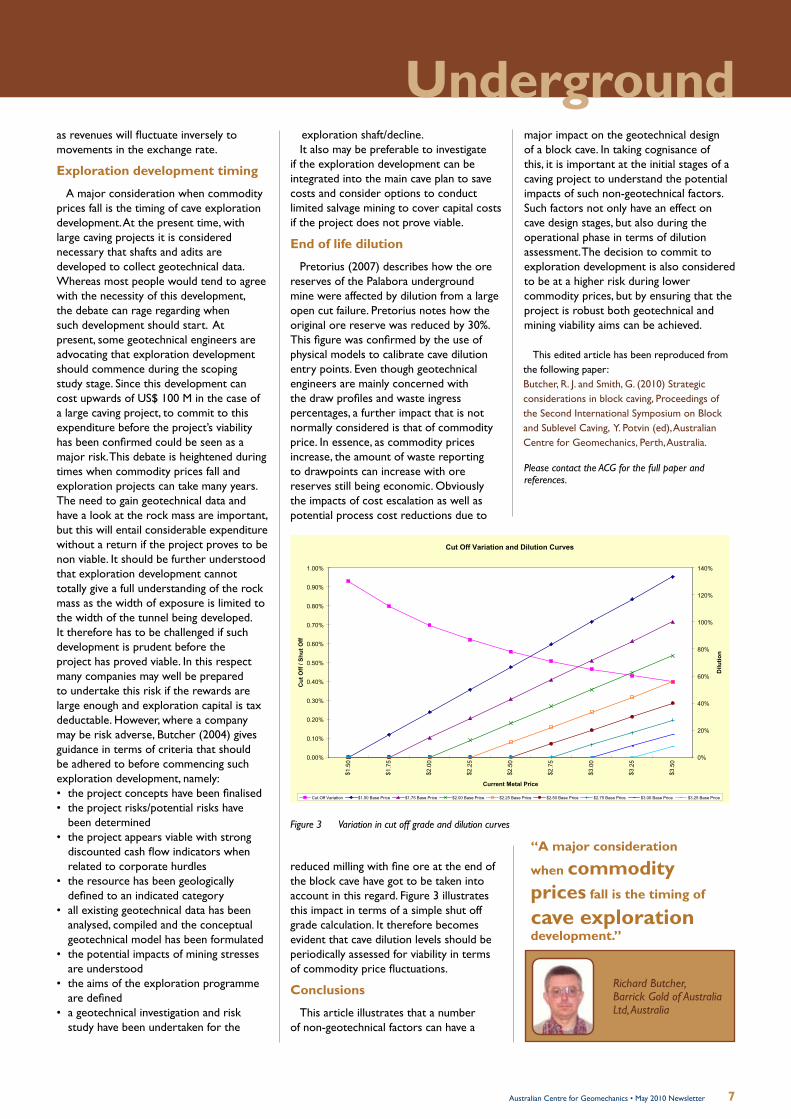
Pretorius (2007) describes how the ore reserves of the Palabora underground mine were affected by dilution from a large open cut failure. Pretorius notes how the original ore reserve was reduced by 30%. This figure was confirmed by the use of physical models to calibrate cave dilution entry points. Even though geotechnical engineers are mainly concerned with the draw profiles and waste ingress percentages, a further impact that is not normally considered is that of commodity price. In essence, as commodity prices increase, the amount of waste reporting to drawpoints can increase with ore reserves still being economic. Obviously the impacts of cost escalation as well as potential process cost reductions due to
reduced milling with fine ore at the end of the block cave have got to be taken into account in this regard. Figure 3 illustrates this impact in terms of a simple shut off grade calculation. It therefore becomes evident that cave dilution levels should be periodically assessed for viability in terms of commodity price fluctuations.
Conclusions
This article illustrates that a number of non-geotechnical factors can have a
Cut Off Variation and Dilution Curves
0.00%
0.10%
0.20%
0.30%
0.40%
0.50%
0.60%
0.70%
0.80%
0.90%
1.00%
$1.
50
$1.
75
$2.
00
$2.
25
$2.
50
$2.
75
$3.
00
$3.
25
$3.
50
Current Metal Price
Cut
Off
/ Shu
t Off
0%
20%
40%
60%
80%
100%
120%
140%
Dilu
tion
Cut Off Variation $1.50 Base Price $1.75 Base Price $2.00 Base Price $2.25 Base Price $2.50 Base Price $2.75 Base Price $3.00 Base Price $3.25 Base Price
Figure 3 Variation in cut off grade and dilution curves
major impact on the geotechnical design of a block cave. In taking cognisance of this, it is important at the initial stages of a caving project to understand the potential impacts of such non-geotechnical factors. Such factors not only have an effect on cave design stages, but also during the operational phase in terms of dilution assessment. The decision to commit to exploration development is also considered to be at a higher risk during lower commodity prices, but by ensuring that the project is robust both geotechnical and mining viability aims can be achieved.
Underground
Richard Butcher,Barrick Gold of Australia Ltd, Australia
“A major consideration
when commodity prices fall is the timing of
cave exploration development.”
This edited article has been reproduced from the following paper: Butcher, R. J. and Smith, G. (2010) Strategic considerations in block caving, Proceedings of the Second International Symposium on Block and Sublevel Caving, Y. Potvin (ed), Australian Centre for Geomechanics, Perth, Australia.
Please contact the ACG for the full paper and references.
8 Australian Centre for Geomechanics • May 2010 Newsletter
cave /kerv/ 1 a hollow in the earth, esp. one opening more or less horizontally into a hill, mountain etc.2 to explore caves , as a sport3 to fall or sink - the roof caved in under their weight4 Caving 2010 – advancing block and sublevel caving practices.
Caving 2010 – advancing block and sublevel caving practices
The Australian Centre for Geomechanics held the Second International Symposium on Block and Sublevel Caving, 20–22 April 2010, in Perth, Western Australia.
The MassMin Symposia is held every four years and is recognised as the main vehicle to disseminate mass mining technologies. However, Professor Dick Stacey of the University of the Witwatersrand, South Africa identified the need for more frequent “meetings”. The ACG, in collaboration with the University of Toronto, Canada, and the University of the Witwatersrand, initiated a specialised series of international symposia on block and sublevel caving. The first symposium was held in Capetown, South Africa in 2007. It is envisaged that the third caving symposium will be held in 2014 in the southern hemisphere; following MassMin 2012, Sudbury, Canada.
More than 200 caving practitioners attended the Caving 2010 symposium that featured state-of-the-art technical presentations and case studies concentrating not only cave mining methods, but the key aspects of engineering design such as undercutting, fragmentation, numerical modelling, preconditioning and ground support.
Prior to the symposium, the ACG hosted a highly interactive Preconditioning Workshop that was attended by more than 60 delegates.
Dr Bill Hustrulid, Hustrulid Mining Services, USA, a world expert in cave mining, opened the caving symposium with an excellent keynote address, ‘Some comments regarding development drifting practices with special emphasis on caving applications’. Dr Hustrulid outlined the situation that many operations need to be aware of and he provided comments from his research undertaken at NIOSH.
“Effective drifting practices are a very important part of modern caving systems. Today, available drilling and blasting technology has developed to the point that there is no reason why the rock mass cannot be ‘cut as with a knife’, is so desired.
One of the missing items in the overall process is a simple, but technically sound, method for assigning the damage radius produced by a particular explosive-hole-rock combination. Through the application of careful perimeter blasting practices, the damage to the remaining rock will be minimal, the shape of the opening will be similar to the as-designed and the succeeding operations such as scaling and rock reinforcement will be easier and more effective. This translates into improved safety and better economy, both of which are essential to modern mining.”
Day two was opened with a keynote address by Dr Gideon Chitombo, Sustainable Minerals Institute, The University of Queensland, ‘Cave mining – 16 years after Laubscher’s 1994 paper ‘Cave mining – state of the art’.’ Dr Chitombo, as the leader of the International Cave Study and Mass Mining Technology was well positioned to provide a comprehensive account of the research outcomes in cave mining during the last sixteen years. His paper sought to provide “a snap-shot of the contemporary caving designs (and practices), highlighting achievements made be the cave mining industry since the introduction of mechanised caving in primary ores. It concludes by listing the developments made in the last 16 years as well as the current and future challenges. The author concludes that contemporary designs and the number of design rules in Laubscher (1994), while still remaining in use, may be reaching their limit when applied to large-scale operations or super caves and they need to be supplemented by a number of the emerging techniques. The attributes which make super caves unique are presented. The opportunity is to continually improve and to test these emerging methods.”
The strong attraction of large mining companies to cave mining methods in recent years is driven by the typical low cost and high productivity of these methods. In particular, block and sublevel caving are the only underground mining
methods that can approach the high productivity and low mining costs of open pit mining. Excellent presentations from Australian operations, including Newcrest Mining Ltd’s Cadia East panel caving project and Telfer Mine; Rio Tinto’s Lift 2 North extension cave project; and Argyle Diamond’s block cave project, demonstrate that local industry is well poised to benefit from this rapidly evolving methodology and practice. It is exciting to note that many local operations are applying preconditioning to their block and panel caving operations. This technique aims to modify the properties of the in situ ore, prior to mining, by inducing new discontinuities using hydraulic fracturing or confined blasting. Preconditioning objectives may be to improve cavability, increase fragmentation or to reduce the seismic risks associated with cave mining.
Presentations from major mining countries from throughout the world were also very well received. Patrick Frenette’s presentation gave a powerful insight into the advanced mining methods undertaken by Goldex Mine, a sublevel open stoping mine near Val-d’Or, Quebec. From the paper, ‘Monitoring open stope caving at Goldex Mine’, Frenette outlined the development of a new mining method – long hole shrinkage. This new method was devised after considering the suitability of the block caving method. It was found that “because of the high quality of the rock mass, numerical modelling suggested the cave would choke itself before the orebody was completely recovered.”
“The orebody was divided in three stopes each consisting of sublevels about 80 m apart. Each sublevel was drilled and blasted in a sequence where the extremity stopes are blasted first and a central stope is mined at a later stage. In the first stages, only the swell of the blasted ore is extracted, the objective being to leave as much ore as possible in the stopes to act as support for the walls. Once the orebody is completely blasted, the ore is removed from the lowest level and any dilution
9Australian Centre for Geomechanics • May 2010 Newsletter
A special thanks to our sponsors
During the three day event, attendees had the opportunity to forge new friendships and catch up with peers and friends alike. Delegates were also able to keep up with the latest products and services by visiting the trade exhibition booths. The ACG was proud to have the support from the following sponsors and exhibitors.
Principal Sponsor: Stratacrete; Major Sponsors: Dyno Nobel and Geotechnical Systems Australia; Industry Sponsor: Cubex; Trade Exhibitors: Beck Arndt Engineering, Geobrugg, Inflatable Packers International, Itasca, JK Tech SMI Technology Transfer, Orica Mining Services and SRK Consulting.
The symposium covered a range of diverse topics. Questions and comments from the audience clearly demonstrated that cave mining is undergoing rapid evolution and that the global mining industry must strive to mitigate the technical risks associated with its growth.
“The most well organised symposium I have attended.”
“A good and useful symposium. Really well coordinated.”
“Great quality papers and presenters.”
coming from the roof or wall is left on top of the ore.”
This very innovative method to mine an orebody, which otherwise could not be exploited economically, uses concepts from different mining methods such as:• “the high efficiency haulage level of a
block cave operation• wall stability of a shrinkage stoping
method• fragmentation of a long hole stoping
method• large blast and mucking flexibility of a
vertical crater retreat method.”Frenette reported that Goldex Mine
had achieved an amazing 1.8 million t blast in one shot (this may well be considered a world record for underground mining), followed by 2 million t caving. It will be interesting to see if this novel and aggressive open stope mining method will be taken up by industry.
Cave mining is a capital intensive method and as such it exposes significant investments to various technical risks. Therefore, successful cave mining in challenging conditions requires extremely high levels of engineering design. The increasing focus on cave mining and the engineering work required to mitigate the technical risks has stimulated new waves of research in this area. This is clearly demonstrated in the presentation given by Christian Frenzel, Herrenknecht AG, Germany for the paper entitled, ‘Shaft boring systems for mechanical excavation of deep shafts’. Herrenknecht AG , in collaboration with Rio Tinto, have developed a new shaft boring system for deep hard rock shafts that significantly improves the health and safety of shaft construction. The new system integrates the excavation, mucking, primary rock support, installation of the final lining, and shaft infrastructure.
“The vertical shaft machine (VSM) is designed for shallow shafts in groundwater bearing soil and soft rock which allows for excavation of pre-sinks. Further development is focusing in extending depth limitations. For deep shafts in hard rock the shaft boring system (SBS) has been developed in collaboration with Rio Tinto. The system uses conventional disc cutting in a unique setup. The mucking system is an integral part of the system and utilises the principle of a bucket wheel excavator and vertical conveyors … Due to high production performance the SBS and VSM can create a positive impact on the overall mine development schedule and help to increase the net present value of the mine
project.”One area generating solid industry
interest was the ongoing challenge to control mine seismicity and rockburst conditions. The technology and knowledge surrounding the identification and management of ground control hazards is evolving rapidly. The ACG’s Mine Seismicity and Rockburst Risk Management project aims to develop innovative tools to assist mine operators to manage seismic risk omnipresent in the ground conditions. The ACG project team also seeks to develop analytical tools to better quantify the hazards associated with rockbursts and mine seismicity.
While geomechanics engineers and mine managers are becoming increasingly aware of seismic monitoring systems, more information and resources are needed to address the dangers associated with what geology is throwing at us – look at the recent Iceland volcanic eruption and the Kalgoorlie earthquake. It is widely accepted that the problem of rockburst and mine seismicity in mines is highly complex, and at best, only partially understood. Yet the consequence of industry’s ignorance can be catastrophic!
The ACG looks forward to hosting the Advanced Application of Seismology in Mines Short Course, 8–11 June 2010, Perth, Western Australia to disseminate the latest ideas and technologies from worldwide research activities. It is based on a Masters level post-graduate course offered at Laurentian University, Canada.
Underground
Caving 2010 attracted excellent international participation with contributions from 11 countries. Fifty high calibre papers are published in the Caving 2010 proceedings. Accompanying these proceedings is a CD Rom containing many of the paper figures in colour.
To order your copy online, please visit www.acg.uwa.edu,au/shop or contact [email protected]
Proceedings of the Second International Symposium on Block and Sublevel Caving

10 Australian Centre for Geomechanics • May 2010 Newsletter
Seal blistering on the Lake Grace Airstrip
The blistering of sprayed seals on granular pavements is an infrequent but destructive event. In February 2007, Golder Associates undertook the task of evaluating the likely causes and potential rehabilitation requirements resulting from such an event on the Town of Lake Grace Airstrip. This town facility is a typical spray sealed airstrip used for light aircraft in rural areas of Australia. Aircraft use tends to be relatively limited. Nevertheless, the strips provide a valuable means of contact to rural communities.
The Lake Grace Airstrip is situated just outside the town of Lake Grace, which is a centre for local farming in the Wheatbelt area of Western Australia and the main town in one of the largest agricultural shires in the state. The strip lies alongside a salt lake and had only been sealed in December 2005 using a 7 mm sprayed treatment. The base was a local, naturally occurring laterite gravel. An extreme rainfall event in January 2006 had resulted in widespread flooding in the general area and the level of water in the lake rising suddenly. The blistering was first noticed in April of 2006, but may have been present on a small scale prior to this.
The form of failure involves the lifting of areas of seal in roughly dome-shaped blisters that then rupture, leading to the collapse of the top of the blister into the wider deformation. The soil within the blister is generally disrupted and
de-compacted to a ‘fluffy’ loose layer.The severity and frequency of these
defects can vary widely, but in the case of the Lake Grace Airstrip it was the most extensive and severe example ever encountered by the author. Blisters were widespread over the airstrip, with very high concentrations in specific areas. It is understood that the area affected was spreading (above photo).
The type of blistering and fluffing observed has been reported and investigated both nationally and internationally. It was fairly common on sections of the Eyre Highway but has occurred over a wide range of conditions in Western Australia. There is some debate as to the mechanisms involved and they probably vary from site to site. It is, however, generally recognised that problems are more likely in high water table or salt water situations. Some research associates the problem with slightly porous seals.
The most likely cause in the circumstance of this airstrip was a suddenly rising saline water table due to flooding, resulting in an increase in air pressure in the base material voids, which did not dissipate laterally and slowly lifted up the relatively soft new seal. Eventually blisters formed, developed holes or cracks, and moisture escaped leading to the deposition of salt. There was a tendency for blisters to form in longitudinal lines that may be related to
slight variations in base density near the surface, or variations in seal mat thickness related to slight variations in the texture of the base finish, or variations in application across the bitumen spray bar.
The cohesionless fluffy appearance of the soil in the blisters can be explained by venting moisture through the ruptured blisters, the growth of salt crystals and possibly a change in the basecourse fines from a dispersed to a flocculated state because of the presence of salt.
A testing programme was proposed to confirm the pavement material properties and the assumptions made concerning the diagnosis of the causes of the problems. A number of potential rehabilitation options were also proposed for consideration by the local government authority. In order of increasing risk they were as follows:• Construct a new raised pavement so
that the highest water table likely is well below the bottom of the basecourse, and prime and seal it with a heavy double coat seal.
• Remove the moist, salt contaminated base, replace, compact, prime and seal with a heavy double coat seal (this option could include cement modification of the new base).
• Remove the blistered seal and the fluffy cohesionless upper base (about 20 mm), overlay with new base material, compact, prime and seal with a heavy double coat seal.The decision the Shire of Lake Grace
makes would be expected to reflect the risk they are willing to assume, plus associated costs and the level of service they wish to provide. The solution selected was to tyne the bituminous surfacing into the basecourse using a recycling machine and to leave the runway unsealed.
Acknowledgement
The permission of the Shire of Lake Grace to publish this article is acknowledged and much appreciated by Golder Associates Pty Ltd.
by Andrew Cray, Golder Associates, Australia
Andrew Cray,Golder Associates, Australia

11Australian Centre for Geomechanics • May 2010 Newsletter
Tailings
To order your copy, go to www.acg.uwa.edu.au/shop
14th International Seminar on Paste and Thickened Tailings
5–7 April 2011, Esplanade Hotel Fremantle, Perth, Western Australia
www.paste2011.com
For event updates and to view the list of more than 70 accepted abstracts,please visit www.minewaste2010.com
29 September – 1 October 2010, Sheraton Perth Hotel, Western Australia
ACG First International Seminar on the Reduction of Risk in the Management of Tailings and Mine Waste
KEYNOTE SPEAKERS
The ACG is delighted to have Gary Bentel, Australia, ‘The real value to the mining industry of of leading-practice waste management’; Michael Shelbourn, Barrick Gold of North America, Inc., USA, ‘Geotechnical design verification and performance assessment of tailings storage facilities’; and Graeme Spiers, Laurentian University, Canada, ‘Development of a future from a mining legacy’, give keynote addresses at Mine Waste 2010.
KEY DATES
Submission of papers: 31 May 2010Managing Tailings and Waste Rock Drainage – Quality and Quantity Workshop: 28 September 2010Mine Waste 2010 Seminar: 29 September – 1 October 2010
PRINCIPAL SPONSOR MAJOR SPONSOR INDUSTRY SPONSOR OFFICIAL MEDIA PARTNER
AUSTRALIAN TAILINGS CONSULTANTS
Seminar ThemesThickening• Underground and backfill• Transportation• Rheology• Surface disposal• Case studies• Emerging issues and technologies•
This volume contains the proceedings of the 13th International Seminar on Paste and Thickened Tailings held in Toronto, Canada in May 2010. It contains 46 technical papers contributed by operators, consultants, suppliers and academics from around the world.
Major SponSor
TraDE EXHIBITor
offIcIal MEDIa parTnEr
SupporTIng SponSorS
Abstracts due: 20 September 2010
12 Australian Centre for Geomechanics • December 2009 Newsletter
Obtaining appropriate design parameters for slopes in highly weathered saprolitesby Andy Fourie, The University of Western Australia, Australia and Allan Haines, South Africa
Introduction
This article focuses on the near surface moderately to extremely weathered material found overlying most open pit mines. The parent rock has undergone significant alteration due to weathering and can no longer be considered in rock mechanics terms. It argues that we cannot simply adopt conventional soil mechanics approaches either, but need to develop specific sampling and testing procedures when designing slopes in this weathered material.
What is a residual soil?
Blight (1997) described a residual soil as “a soil-like material derived from the in situ weathering and decomposition of rock which has not been transported from its original location.” The key phrase in this definition is ‘soil-like’. A residual soil has many mechanical properties that are similar to those of transported soils where we can use classical soil mechanics, however, there are aspects that in fact differentiate these materials from conventional soils and therefore, simply adopting soil mechanics approaches can be misleading.
Residual soils retain relict fractures or fissures. They may have some residual cementing, or bonding, which provides some degree of true cohesion between particles. As a result they may display no apparent effect of preconsolidation, even if erosion of overburden has occurred. This is because the competent cemented bonds may prevent void ratio changes due to loading and unloading. Another apparently anomalous consequence of the retention of cemented bonds are the extremely high void ratios that are sometimes encountered in these materials. It is not uncommon to find void ratios in excess of one or even two.
As it is a soil-like material, the effect of pore water pressure cannot be ignored, which means that use of a total stress approach is inadequate. It is necessary to think in terms of effective stresses, but even then the impact of residual structure must be remembered and understood.
Residual soils from a project in West
Africa are discussed. The soils are characterised as saprolites, where the definition used is, “thoroughly decomposed rock, a clay rich soil formed in place by chemical weathering of igneous or metamorphic rocks”, as given in Geological Society Engineering Group Working Party (1990).
Do micro-features or macro-features dominate?
Typically a material considered as soil-like is expected to behave as a continuum and the material porous. Strength would also be characterised in terms of a continuum approach, where the shear strength is mobilised through an essentially intact matrix of particulate material. In comparison, when considering a competent rock mass, it would be more usual to consider water flow along joints or fissures, and to be more concerned about the strength properties of these discrete features than the properties of the intact material. When dealing with saprolites we need to consider both these possibilities or an interaction and design for the most likely case.
Choice of appropriate permeability
It is much easier to test the intact (continuum) permeability of a saprolite than it is to test the permeability of a residual discontinuity (assuming it can be identified in the first place). However, often surface water penetrates saprolite profiles very rapidly, causing rapid changes in pore water conditions, leading to slope instabilities (Gerscovich et al., 2006). Such rapid inflow of water can only occur along discontinuities and therefore they need to be identified and characterised.
It is appropriate to consider both intensity and duration of rainfall as important contributors to potential instability (Lumb, 1975, Fourie, 1996). Recognising this effect, design and management of an open pit operation can be tailored to suit local conditions. It may be possible, for example to:• operate certain sections of the pit
only during the dry season and avoid susceptible areas during the period when sudden and unpredictable rainfall events are possible.
• monitor changes in pore water pressure providing early warning of potential problems. This does require determination of the fracture network in order to locate the piezometers appropriately.
Figure 1 Illustration of definition of effective stress strength parameters
Mean stress
Shear stress
Angle of internal friction, φ´
Apparent cohesion, c´
3.1 Choice of appropriate permeability It is certainly much easier to test the intact (continuum) permeability of a saprolite than it is to test the permeability of a residual discontinuity (assuming it can be identified in the first place). However, there is much evidence, both anecdotal and published, that stormwater penetrates saprolite profiles very rapidly, causing rapid changes in pore water conditions, often leading to slope instabilities (Gerscovich et al., 2006). Such rapid inflow of water can only occur along discontinuities and therefore they need to be characterised.
There are many studies of the effect of rainfall on the stability of natural slopes in tropical and residual soils (Lumb, 1975, Fourie, 1996) and the lessons from these studies are equally relevant to excavated slopes such as those in open-pit mining. For example, it is now accepted that it is inappropriate to consider potential rainfall impacts only in terms of rainfall intensity (such as setting a threshold intensity above which potential instability may be expected), but rather that antecedent conditions are critical, and that both intensity and duration are important contributors to potential instability. Recognising this effect, design and management of an open pit operation can be tailored to suit local conditions. It may be possible, for example to:
• Design certain sections of the pit for operation only during the dry season, thereby avoiding excavation and other work during the period when sudden and unpredictable rainfall events are possible, and
• Install systems that monitor changes in pore water pressure and thereby track the antecedent moisture conditions in a slope, providing early warning of potential problems. The difficulty with this technique is the non-continuum nature of many saprolite profiles mentioned earlier, which makes it difficult to know where to locate a piezometer to provide a representative measure of in-situ pore pressures.
Figure 2: Illustration of definition of effective stress strength parameters
3.2 Choice of appropriate strength parameters In the analysis of soil slopes using limit equilibrium methods, the required strength parameters for an effective stress analysis are the angle of internal friction, φ´, and the apparent cohesion, c´. It must be emphasised that c´ is not a true cohesion, but is in fact merely an artefact of the way that strength test results are plotted. This is explained in Figure 2, which shows typical results from triaxial compression tests on three specimens consolidated to different initial stresses, shown as the solid semi-circles. The failure envelope that confines these Mohr circles is a straight line, as shown, which has an intercept on the y-axis which is the apparent cohesion. However, this intercept is merely a convenient way of defining a straight line. There is now much evidence in the geotechnical literature that under low effective stresses, the mobilised strength is in fact lower than that given by the straight line envelope shown in Figure 2. The true failure envelope is in fact one that is tangential to the circle shown dotted in Figure 2. Despite this anomaly, the use of apparent cohesion in a straight-line fit of strength data has served the industry well and is now universally accepted. It is discussed here in some detail because in most saprolites the y-axis intercept is a

13Australian Centre for Geomechanics • May 2010 Newsletter
Open pitChoice of appropriate strength parameters
For soils, we can determine the effective angle of internal friction, φ´, and the apparent cohesion, c´ (this is not a true cohesion, but due to the way that strength test results are plotted as shown in Figure 1). At low effective stresses, the mobilised strength is in fact lower than that given by the straight line envelope shown in Figure 2 (coinciding with near surface conditions in pit walls). The true failure envelope is tangential to the circle shown dotted in Figure 1. However, in most saprolites the y-axis intercept is a true cohesion, due to the cemented bonds, and therefore can be relied on even under low stress conditions.
The shear strength of a soil, τf , is usually defined as:
τf = c´+ σ´tan ø´ (1)
where σ´ is the effective stress acting normal to the plane on which the shear strength is mobilised.
Typically we are dealing with unsaturated soils and negative pore water pressure, or suction, that occurs when the degree of saturation falls below about 85%. Referred to as matrix suction, it has the effect of increasing the effective stress, σ´, referred to above, and therefore the available shear strength. This suction can change with time. It is because of this effect that many soil slopes are able to remain stable at slope angles that are steeper than would be predicted by Equation (1). Many of these slopes fail during periods of heavy or prolonged rainfall as the degree of saturation of the soil increases, without necessarily reaching 100%, which causes the matrix suction to decrease and the additional strength component to disappear. This time dependent response and time to failure is difficult to predict.
Taking account of brittleness when defining strength parameters
There is another potential issue to be considered when defining appropriate shear strength for use in limit equilibrium stability evaluations. This relates to the potential brittleness, or strain softening, that is characteristic of many saprolites.
Strain softening is illustrated in Figure 2. This shows a typical stress–strain plot for a test on a saprolite. As shown, the shear stress reaches a peak, indicated as τp, after which the available shear strength decreases until a residual value, τr, is reached. When plotting the Mohr stress
circles, such as shown in Figure 1, the question then arises which value of shear strength to use, the peak or the residual? Using the peak value may be unsafe, because if the peak strength is mobilised, even only locally, the load carrying capacity in this region will decrease and progressive failure of the entire slope may occur very suddenly (Troncone, 2005). However, using the residual strength will result in the requirement of very flat slopes, which will be not only expensive but also perhaps totally unnecessary. After all, we are then ignoring two factors that result in a strength that is higher than the residual value – the peak strength and the contribution due to matrix suction. Design needs to take account of the expected strain in the slope.
The brittleness of many saprolites can result in a distortion of the available shear strength, if suitable sampling and testing techniques are not used. The vast majority of soil samples for strength testing are
recovered in the field using one of a variety of tube sampling techniques. The assumption is that if this process is carried out carefully the resulting soil samples will be undisturbed and when tested will provide representative strengths. However, as shown by Baligh (1985), the compressive strains induced by very careful insertion of a thin walled sampling tube are still of the order of 2 to 4%. This may be sufficient to cause enough compression of the residual soil sample to severely damage the cemented bonds, resulting in densification of the sample and an increase in strength. If the increase in the sample density is significant, subsequent triaxial testing will
Figure 2 Illustration of strain softening and the difference in peak and residual strength
not display the brittle behaviour illustrated in Figure 2, as the sample will be dilative (due to the higher density) virtually from the start of testing. The brittleness, which can have severe consequences, will be totally overlooked as a result and the test results aggressive.
Appropriate sampling procedures to ensure samples are representative
A sensible approach in saprolites would be to obtain block samples if possible. The disadvantages of block sampling are the time required to obtain a decent block, and the fact that samples cannot be recovered from the base of a borehole, but rather require a few square metres of working area. However, given the high cost of even conventional sampling procedures, the potential for obtaining truly representative samples for testing and design purposes will far outweigh the negative aspects.
Case historyThe following case history presents an
example of a suitable sampling and testing programme for determining saprolite properties.
Background to the mining conditions
SRK Consulting was appointed by Société Ashanti Goldfields De Guinée (SAG) to carry out an investigation of a slope failure in the Sanu Tinti Stage 1 pit and to initiate a re-design of the Sanu Tinti Stage 2 and Eureka open pits in Guinea. Previously in 1998, the Stage 1 pit at Sanu Tinti had failed on both the footwall and hangingwall slopes. All of the pit slopes
0
200 400 600 800 1000
1200
1400
1600
0 5 10 15 20
Axial strain (%)
Shear stress (kPa)
τp τr
Strain softening is illustrated in Figure 2. This shows a typical stress-strain plot for a test on a saprolite. As shown, the shear stress reaches a peak, indicated as τp, after which the available shear strength decreases until a residual value, τr, is reached. When plotting the Mohr stress circles such as shown in Figure 1, the question then arises which value of shear strength to use, the peak or the residual? Using the peak value may be unsafe, because if the peak strength is mobilised, even only locally, the load carrying capacity in this region will decrease and progressive failure of the entire slope may occur very suddenly (Troncone, 2005). However, using the residual strength will result in the requirement of very flat slopes, which will be not only expensive but also perhaps totally unnecessary. After all, we are then ignoring two factors that result in a strength that is higher than the residual value – the peak strength and the contribution due to matrix suction. Design needs to take account of the expected strain in the slope.
The brittleness of many saprolites can result in a distortion of the available shear strength, if suitable sampling and testing techniques are not used. The vast majority of soil samples for strength testing are recovered in the field using one of a variety of tube sampling techniques. The assumption is that if this process is carried out carefully and the resulting soil samples will be undisturbed. When tested, the samples will provide representative strengths. However, as shown by Baligh (1985), the compressive strains induced by very careful insertion of a thin walled sampling tube are still of the order of 2% to 4%. This may be sufficient to cause enough compression of the residual soil sample to severely damage the cemented bonds, resulting in densification of the sample and an increase in strength.
Figure 2: Illustration of strain softening and the difference in peak and residual strength
If the increase in the sample density is significant, subsequent triaxial testing will not display the brittle behaviour illustrated in Figure 2, as the sample will be dilative (due to the higher density) virtually from the start of testing. The brittleness, which can have severe consequences, will be totally overlooked as a result and the test results aggressive.
4 Appropriate sampling procedures to ensure samples are representative
A sensible approach in saprolites would be to obtain block samples if possible. The disadvantages of block sampling are the time required to obtain a decent block, and the fact that samples cannot be recovered from the base of a borehole, but rather require a few square metres of working area. However, given the high cost of even conventional sampling procedures, the potential for obtaining truly representative samples for testing and design purposes will far outweigh the negative aspects.
5 Case History
The following case history presents an example of a suitable sampling and testing programme for determining saprolite properties.

14 Australian Centre for Geomechanics • May 2010 Newsletter
Figure 3 View of the footwall slope following the failure at Sanu Tinti in 1998
Block sampling of the saprolites
High quality samples of the saprolites were obtained for determination of appropriate design parameters. Conventional tube sampling procedures were rejected in favour of block sampling procedures and three blocks in all were recovered from two exposures. Two of these were from the Sanu Tinti pit and one from the nearby proposed Eureka Hill pit. The blocks were typically cubic, with side lengths of about 40 cm. After excavating and trimming the blocks, they were coated with layers of wax and plastic film, before being packed into individual wooden crates that were then filled with sawdust. The crates were air-freighted to the laboratory.
Description of material and index test results
Table 1 summarises the key characteristics obtained from laboratory tests on the saprolite. The particle size distribution curves for the three materials are shown in Figure 4. Particular care was taken when preparing samples for the Atterberg Limit tests (the liquid and plastic limits) and the particle size distribution tests. As discussed by Fourie (1997), oven drying of these soils results in major alterations to the material structure that causes inconsistent test results when the above tests are conducted. All samples were therefore air dried before testing.
Table 1 Key characteristics of saprolite from the Siguiri mine site
Note: The laboratory derived shear strength parameters are for saturated, consolidated and drained test conditions.
were in saprolite. The footwall slope had failed as a classical circular slip along its entire 250 m length while the hangingwall had failed through discrete wedge style block failures.
The existing design for the saprolites was for overall slope angles of between 42 and 55° for the slope above the ground water surface and slopes of between 22 and 35° for slopes below. The higher values were for slopes <25 m in height and the lower values were for slopes up to 100 m in height. The bench face angle was recommended as 68° with a 10 m bench height above the ground water surface and 5 m below. A view of the footwall slope failure is provided in Figure 3. The dark line of vegetation curving half way down the face was originally at ground surface. The slope height shown in the figure is approximately 50 m.
Characteristic Sanu Tinti 1Footwall Slope
Sanu Tinti 2Hangingwall Slope Eureka Hill
Liquid limit (%) 53 46 41-45Plasticity index (%) 36 23 33-35Specific gravity 2.82 2.71 2.7Void ratio 0.83-0.92 0.48-0.52 0.78-1.09In situ degree of saturation % - dry season 52 63 48
% - wet season - - 89USCS classification ML CL MLMineralogy (in order of decreasing proportion)
Kaolinite, Quartz, mica Quartz, montmorillonite Quartz, kaolinite, illite, microcline
Intact permeability (cm/sec) - - 3x10⁻⁶
Cohesion (kPa): see note 106 227 28Friction angle (º): see note 20 22 21
15Australian Centre for Geomechanics • May 2010 Newsletter
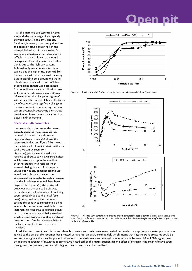
Open pitAll the materials are essentially clayey
silts, with the percentage of silt typically between about 75 and 80%. The clay fraction is, however, consistently significant and probably plays a major role in the strength behaviour of the saprolite. For example, the friction angle values shown in Table 1 are much lower than would be expected for a silty material, an effect that is due to the high clay content. Although only one complete test was carried out, the high in situ permeability is consistent with that reported for many sites in saprolitic soils around the world. It is also consistent with the coefficient of consolidation that was determined from one-dimensional consolidation tests and was very high, around 350 m2/year. Information on the change in degree of saturation at the Eureka Hills site illustrates the effect whereby a significant change in moisture content occurs during the rainy season, potentially destroying the strength contribution from the matrix suction that occurs in drier material.
Shear strength parameters
An example of the results that were typically obtained from consolidated, drained triaxial tests are shown in Figure 5, where Figure 5(a) shows the stress–strain data and Figure 5(b) shows the variation of volumetric strain with axial strain. As can be seen from Figure 5(a), peak shear strengths are reached at about 2 to 4% axial strain, after which there is a drop in the mobilised shear resistance, with residual shear strengths being about half of the peak values. Poor quality sampling techniques would probably have damaged the structure of the samples to such an extent that this brittleness may well have been disguised. In Figure 5(b), the post-peak behaviour can be seen to be dilative, particularly at the lower value of confining stress, probably due to the initial (pre-peak) compression of the specimens causing the density to increase to a point where dilation becomes possible. It is also important to note that no dilation occurs prior to the peak strength being reached, which implies that the true (bond-induced) cohesion must first be overcome before the large strain frictional strength is mobilised.
0102030405060708090
100
0.001 0.01 0.1 1
Particle size (mm)Pe
rcen
t pas
sing
(%)
ST1 ST2 EH
Figure 4 Particle size distribution curves for three saprolite materials from Siguiri mine
-0.8
-0.6
-0.4
-0.2
0
0.2
0.4
0.6
0 5 10 15 20
Axial strain (%)
Vo
lum
etr
ic s
tra
in (
%)
500 600 800
0100200300400500600700800900
0 5 10 15 20
Axial strain (%)
She
ar s
tres
s (k
Pa)
500 600 800
-0.8
-0.6
-0.4
-0.2
0
0.2
0.4
0.6
0 5 10 15 20
Axial strain (%)
Vo
lum
etr
ic s
tra
in (
%)
500 600 800
0100200300400500600700800900
0 5 10 15 20
Axial strain (%)
She
ar s
tres
s (k
Pa)
500 600 800
Figure 5 Results from consolidated, drained triaxial compressive test, in terms of shear stress versus axial strain (a), and volumetric strain versus axial strain (b). Numbers in legend refer to the effective confining stress in the triaxial test in kPa
(a)
(b)
In addition to conventional triaxial and shear box tests, two triaxial tests were carried out in which a negative pore water pressure was applied to the base of the specimen being tested, using a high air-entry ceramic disk, which meant that negative pore pressures could be ensured throughout the shearing phase. In these tests, the maximum shear strength was found to be between 10 and 60% higher than the maximum strength of saturated specimens. As noted earlier, the matrix suction has the effect of increasing the mean effective stress throughout the specimen, meaning that higher shear strengths can be mobilised.

16 Australian Centre for Geomechanics • May 2010 Newsletter
ACG Mining in Saprolites Workshop
26 July 2010, Burswood Convention Centre, Perth
Please visit www.acg.uwa.edu.au/events_coursesfor the workshop programme and to
register for this event.
SLOPE STABILITY DESIGN SECTION
300
325
350
375
400
425
450
0 100 200 300 400 500Length (m)
Ele
va
tio
n (
m)
50N
FW
N
N 370
320
50HW
25o Overall
N
380
25o Overall
Figure 6 Slope stability design section
Slope design considerations
A series of slope stability analyses were carried out to determine the appropriate slope angle, slope height and drainage constraints to achieve stable slopes. Both 2D FLAC and limiting equilibrium analyses were carried out to generate a set of slope design recommendations. The design section used for these analyses, illustrating both the existing and proposed final pit slopes and dewatering scenarios, is shown in Figure 6.
The laboratory testing of the intact material (for saturated, drained conditions) produced maximum values of 106 kPa cohesion and 20° friction, although some of the tests produced cohesion values of as low as 20 kPa, with friction angles once again as low as 20°. The higher cohesion value is indicative of the material without relic structures and remote from major discontinuities. It is evident that water management and drainage can have a beneficial impact on the shear strength and resultant performance of the pit slopes. The resultant overall slope angle for the final 100 m high pit slope would be 25° (with drainage) and 18° (limited drainage).
Conclusions
Selection of shear strength parameters for the design of open pit slopes in saprolites is not straightforward. The recommended approach is to utilise results from laboratory tests of specimens taken from high quality block samples.
The process of excavating, trimming and transporting blocks of undisturbed soil is not trivial. It requires personnel who appreciate the importance of the sampling procedure being adopted, as it is vital that truly undisturbed samples are recovered,
otherwise the entire exercise is futile. However, the potential benefits of carrying out such a sampling procedure, and of undertaking appropriate laboratory testing on the recovered samples, should prove to far outweigh the inconveniences.
The benefits of this study are that it clearly shows that for major excavations in saprolitic material, and indeed it is true for most residual soils, a simplistic approach to shear strength selection is inappropriate and likely to be unconservative. This is because higher estimates of both cohesion and the angle of internal friction may be obtained.
Acknowledgements
The authors thank the mine management at Société Ashanti Goldfields De Guinée (SAG) for their permission to publish the case history study. Allan Haines thanks the staff at SRK Consulting, Perth for their assistance with the preparation of this article.
Andy Fourie, The University of Western Australia, Australia
The main objective of the workshop is to identify what is known and what is not known in the investigation, analysis and
design of pit slopes in saprolites, transported materials and laterites.
This ACG workshop will be held immediately prior to The AusIMM’s Seventh Large Open Pit Mining Conference 2010 to be held at the Burswood Convention Centre, 27–28 July 2010. Visit www.ausimm.com.au/lop2010/
Most open pit mines in Australia, Indonesia, Brazil, Africa and several in North America, start mining in completely weathered to highly weathered materials. The depth can vary from a few metres to the deepest recorded pit to date at 170 m below surface. Often, sampling in these materials is poorly undertaken, resulting in strength estimates that are significantly greater than the true in situ strength. The influence of clay alteration, leaching and variable cementation makes generalisation of material behaviour difficult. The orientation spacing and continuity of relic structure is often difficult to determine unless there is exposure, and then it may be smeared by the mining process. Structural data may be available in the fresh rocks but is often ignored for this important aspect.
This edited article has been reproduced from the following paper;Fourie, A.B. and Haines, A. (2007) Obtaining appropriate design parameters for slopes in highly weathered saprolites, Proceedings of the 2007 International Symposium on Rock Slope Stability in Open Pit Mining and Civil Engineering, Y. Potvin (ed), Australian Centre for Geomechanics, Perth, Australia.
Please contact the ACG for the full paper and references.
Workshop ThemesGeological impact; structural setting; hydrothermal alteration; soils; dispersive behaviour; slaking; smectites; pore pressure; hydro-mechanical coupling; relict structure; mechanisms of failure; deformation response; analysis techniques; run-out; operational constraints; effective dewatering; mining residual soils; sampling and testing; engineering geology of saprolites; monitoring; case studies.
Lead presentersPhil Dight, Australian Centre for Geomechanics; and Andy Fourie, The University of Western Australia.

17Australian Centre for Geomechanics • May 2010 Newsletter
Mine closure planning in South America
These guidelines were published in 2009 as one of the results of the Large Open Pit (LOP) project sponsored by Anglo American plc, Barrick Gold Corporation, BHP Billiton Innovation Pty Ltd, Corporacion Nacional Del Cobre De Chile (CODELCO), Compania Minera Dona Ines de Collahuasi SCM (Collahuasi), DeBeers Group Serices Pty Ltd, Debswana Diamond Company, Newcrest Mining Limited, Newmont Mining Limited, the Rio Tinto Group, Vale, and Xstrata Queensland Limited. Contributions to the guidelines were provided by 18 authors.
This guideline is a must have publication that can be used by mine based geotechnical engineers, geologists and mining engineers, as well as in consulting practices. It is a welcome addition to CANMET’s “Pit Slope Manual” (1977b), “Rock Slope Engineering” (1981), and “Slope Stability in Surface Mining”(2000).
The guidelines follow the logical sequence from project development to mine closure. It includes chapters on field data collection, development of a geological model, structural model, rock mass model and hydrogeological model, culminating in the geotechnical model for
the project. There are chapters on dealing with data uncertainty and quantitative risk assessment. Slope design methods are presented. An important aspect is covered in the design implementation; a subject often forgotten by analysts. Slope stability monitoring, risk management and pit closure are also covered.
The guidelines provide comprehensive tables of what should be undertaken at different stages of a project which will help geotechnical engineers to develop appropriately funded investigations.
The guidelines are squarely aimed at deep, hard rock mines predominantly controlled by structural failure mechanisms. There is mention of mining in saprolites and weathered rock masses cautioning the reader, but this was not covered in any detail. The section dealing with the synthetic rock mass model compared to more widely adopted rock mass characterisations, e.g. RMR, MRMR,Q, and/or GSI, is still a work in progress.
While all slope failures involve a driving stress exceeding the available strength, it was a surprise that the topic of stress measurement and stress induced failure had limited coverage.
Open pitBOOK REVIEWby Phil Dight, Winthrop Professor of Geotechnical Engineering, Australian Centre for Geomechanics
Guidelines for OpenPit Slope Design Editors: John Read and Peter Stacey
Phil Dight, Australian Centre for Geomechanics, Australia
This of course leaves room for a second edition.
The reference list is comprehensive for people needing to know more about the topic.
Guidelines for Open Pit Slope Design can be purchased from CSIRO Publishing.
www.publish.csiro.au
Recommended reading
CANMET (1977) Pit Slope Manual, • Chapter 5 ‘Design’, Energy, Mines and Resources Canada, Ottowa.Hoek, E. and Bray, J. (1981) Rock Slope • Engineering, 3rd edition, IMM, London.Hustrulid, W.A., McCarter, M.K. and • Van Zyl, D.J.A. (2000) Slope Stability in Surface Mining, Society for Mining, Metallurgy and Exploration.
Proceedings of the ACG’s 2007 International Symposium on Rock Slope Stability in Open Pit Mining and Civil Engineering held in Perth, Western Australia.
Slope Stability 2007
To purchase online, please visit www.acg.uwa.edu.au/shop
PUBLISHING

18 Australian Centre for Geomechanics • May 2010 Newsletter
Principal Sponsor
Pontificia Universidad Católica de Chile, in collaboration with the Australian Centre for Geomechanics, the University of Toronto, and the University of the Witwatersrand, is hosting the 5th International Seminar on Deep and High Stress Mining.For more details contact [email protected] or visit http://web.ing.puc.cl/~deepmining2010/
Collaborating Organisations
5thInternational Seminar on Deep and High Stress Mining
20106–8 October | Santiago - CHILE
Seventh Large Open Pit Mining Conference 2010
27–28 July 2010, Perth, Western AustraliaHigh demand for commodities, record fuel prices and a scarcity of skilled personnel have been replaced and surpassed by the recent global financial crisis as the primary issues facing the mining industry. As demand for commodities improves, the incentive to continue to drive operational and safety improvements will become paramount. The Seventh Large Open Pit Mining Conference 2010 (LOP 2010) will provide the opportunity to chart that progress in large open pit mines around the world.
The conference will provide the forum for operations with major achievements, along with those operators implementing changes, the chance to outline their innovations and to share and explore experiences with others. Consistent with the aims of The AusIMM, the conference will allow members and the industry to keep abreast of technical developments and provide a forum to share views and opinions within the large open pit sector.
For more information, please contact: Belinda Martin, The AusIMMPhone: +61 3 9658 6125 Fax: +61 3 9662 [email protected]
Events of interest
A workshop and meeting will be held on 27–28 May 2010 in Brisbane on “Application of Various Ground Control Techniques to Specific Mining Methods: An Industry Perspective”. A keynote address will be given by Dr William Bawden, University of Toronto, Canada. Please contact the EAGCG for details.
– Long term water management
– Mine site reclamation &
rehabilitation
– Control & monitoring
– Soil ecology
– Legal & regulatory issues
– Mining heritage & tourism
– Recent closure case studies.
5th International Conference on Mine Closure
Hosted by Founding Bodies
23 ---> 26 november 2010. Viña del Mar, Chile
Responsible closure: living up to communities’ and stakeholders’ expectations
conference themes
Over 120 abstracts that promise a diverse and solid technical programme have been approved for mine closure 2010. The conference will explore the following areas:
Early Bird Registration until 23 August
Register now at www.mineclosure2010.com
– Community development
– Proactive stakeholder engagement
– Mine cluster, redeployment,
redevelopment & decommissioning
– Retrenchment
– Mine legacies & relinquishment
– Designing & planning for closure
– Progressive closure planning
– Closure costs & financing
enquiries
Olga Cherepanovaevent coordinatorTelephone: + 56 2 652 1519E-mail: [email protected]

19Australian Centre for Geomechanics • May 2010 Newsletter
www.strategic2011.com
9–11 November 2011, Novotel Langley Perth,
Western Australia
ACG FOURTH INTERNATIONAL SEMINAR ON STRATEGIC
vERSUS TACTICAL APPROACHES IN MINING
Since 2005, this series of international seminars on strategic versus tactical issues in mining has been well attended by senior mining professionals and manages in Australia, South Africa and Canada. The ACG is pleased to bring this innovative and highly topical seminar back to Perth.
ACG newsACG Board of Management
Currently, the ACG Board of Management comprises of Joint Venture Partner representatives: Associate Professor Peter Kinny, WA School of Mines, Curtin University of Technology; Dr Steve Harvey, CSIRO Exploration and Mining; Professor John Dell, The University of Western Australia; Professor Yves Potvin, ACG, and industry representatives Ian Suckling (chairman), Newmont Asia Pacific; Richard Butcher, Barrick Gold of Australia; and Christopher Stone, BHP Billion Nickel West Pty Ltd. The Board meets up to four times a year to provide strategic direction for the centre, review and approve activities and operations and to provide counsel.
The Board assists the centre to focus on activities that intensely support the mining industry by way of applied research projects that have a direct, practical application to operations, and the relevant training and education required to optimise their application.
The ACG Board and staff members express their sorrow for the recent passing of Board member Professor Paul Dunn.
Professor Dunn, Director of the WA School of Mines (WASM), Curtin University of Technology passed away after a battle with cancer. Paul was a relatively young man of enormous energy who enthused his staff and was universally liked and respected.
ACG Corporate Affiliate Memberships
Excellent support and encouragement for the Australian Centre for Geomechanics initiatives and activities by industry is demonstrated by our Corporate Affiliate Memberships. The ACG presently has 15 highly valued affiliate members that receive exclusive benefits such as discounted ACG event registration fees and reduced costs for the centre’s publications and training products. These memberships are fundamental in assisting the centre to play a critical role in indentifying and developing research projects and professional education in Australia and more recently overseas. This is significant as industry enters a new growth phase and increases the number of large open pits and deeper underground mining operations.
Paul joined Curtin two and a half years ago and oversaw the significant development of the School of Mines. He played a prominent role in enhancing the research base of the School and made important contributions to faculty planning. He also initiated the development of a far-sighted strategic plan for WASM which he was working on even when his health was deteriorating noticeably. Although he was sadly unable to complete this work, he has left a legacy for others in WASM to follow.
The ACG is very appreciative of Paul’s outstanding contribution to its Board. His dedication and active promotion of the ACG and industry to the general community helped advance a positive mining industry image throughout the world. Paul’s knowledge, experience and strong business acumen were instrumental in assisting the Board to develop new directions and initiatives for the ACG.
Our deepest sympathy goes to Paul’s family and peers.
promoting best practice in strategic planning
AUSTRALIAN TAILINGS CONSULTANTS
2010 Corporate Affiliate Members
Professor Paul Dunn, Director of the WA School of Mines (WASM), Curtin University of Technology

20 Australian Centre for Geomechanics • May 2010 Newsletter
ACG Event Schedule*Environmental Geochemistry of Mine Site Pollution – An Introduction Short Course Perth, 26–27 May 2010
Advanced Application of Seismology in Mines Short Course Perth, 8–11 June 2010
Mining in Saprolites Workshop Perth, 26 July 2010
Open Pit Rock Mass Modelling Seminar Perth, 29–30 July 2010
Ground Support on Mining (Basic Level) Short Course Perth, 25–27 August 2010
Managing Tailings and Waste Rock Drainage – Quality and Quantity Workshop Perth, 28 September 2010
First International Seminar on the Reduction of Risk in the Management of Tailings and Mine Waste
Perth, 29 September – 1 October 2010
Blasting for Stable Slopes (Open Pit) Short Course Perth, 17–19 November 2010
In-Pit Waste Storage and Management Seminar Perth, 8–9 December 2010
International Forum on Safe and Rapid Mining Productivity Development Canberra, 24 March 2011
14th International Seminar on Paste and Thickened Tailings Perth, 5–7 April 2011
Geotechnical Engineering for Open Pit Mines Seminar Perth, 17–18 May 2011
Data Driven Slope Design Workshop Perth, 19 May 2011
Fourth International Seminar on Strategic versus Tactical Approaches in Mining Perth, 9–11 November 2011
* The ACG event schedule is subject to change. For event updates, please visit www.acg.uwa.edu.au/events_and_courses
Australian Centre for Geomechanics PO Box 3296 – Broadway, Nedlands, Western Australia, AUSTRALIA 6009Ph + 61 8 6488 3300 Fax +61 8 6488 1130 [email protected] www.acg.uwa.edu.au
ACG Underground Drilling and Blasting – A safety training DVD for underground metalliferous mine workers
All underground mine workers will be exposed to drilling and blasting processes. The aim of this new DVD is to provide workers with critical knowledge on drilling and blasting to aid appreciation of the importance of these mining processes and their related hazards. The DVD will feature an introduction to the rock breaking process in mining and a description of explosives and how they work. The second part of the DVD will cover development drilling and blasting practices; while the third part will cover production drilling and blasting. The new ACG DVD will be available in late 2010. The ACG acknowledges the project sponsors’ generous support.
For many mining companies, ACG training products have become an integral and essential component of their training programmes. For the full list of the ACG’s geotechnical mine worker training DVDs, please visit www.acg.uwa.edu.au/training_products.

ACG May 2010 Newsletter Article References
Shaft boring systems for mechanical excavation of deep shafts by Christian Frenzel and Werner Burger, Herrenknecht AG, Germany, and Fred Delabbio, Rio Tinto, Australia
Suhm, W. (2006) Area of Application of Mechanised Tunneling in the Mining Industry, P.N. Martens (ed), in AIMS Proceedings Rapid Mine Development, pp. 523–536.
Strategic considerations in block caving by Richard Butcher and George Smith, Barrick Gold of Australia Ltd, Australia
Areneda, O. and Sougarret, A. (2007) Keynote Address: Lessons learned in cave mining: El Teniente 1997–2007, in Proceedings First International Symposium on Block and Sub-level Caving, Southern African Institute of Mining and Metallurgy, Johannesburg, South Africa, pp. 59–72.
Bartlett, P.J. and Croll, A. (2000) Cave mining at Premier Diamond Mine, in Proceedings MassMin 2000, Australasian Institute of Mining and Metallurgy, Melbourne, Victoria, pp. 227–235.
Beck, D., Arndt, S., Thin, I., Stone, C. and Butcher, R. (2006) A conceptual sequence for a block cave in an extreme stress and deformation environment, in Proceedings Deep and High Stress Mining, Australian Centre for Geomechanics, Perth, Australia, pp. 65–76.
Butcher, R.J. (1999) Design rules for avoiding draw horizon damage in deep level block caves, Southern African Institute of Mining and Metallurgy, Johannesburg, South Africa, Vol. 00, No. 2, pp. 151–155.
Butcher, R.J. (2000) Block cave undercutting – aims, strategies and methods and management, in Proceedings MassMin 2000, Australasian Institute of Mining and Metallurgy, Melbourne, Australia, pp. 113–119.
Butcher, R.J. (2003) Cave Mining Geomechanics, course notes, Australian Centre for Geomechanics, Perth, Australia. Butcher, R.J. (2004) DEESA – An approach to determine if an orebody will cave, in Proceedings MassMin 2004, Santiago, Chile, pp.
49–54. Butcher, R.J. and Thin, I.G.T. (2007) The inputs and choices for predicting fragmentation in block cave projects, in Proceedings First
International Symposium on Block and Sub-level Caving, Southern African Institute of Mining and Metallurgy, Johannesburg, South Africa, pp. 35–49.
Flores, G. and Karzulovic, A. (2004) Current practices and trends in cave mining, in Proceedings MassMin 2004, Santiago, Chile, pp. 83–90.
Pretorius, D. (2007) The effect of dilution on the underground block cave ore reserves at Palabora Mining Company, in Proceedings First International Symposium on Block and Sub-level Caving, Southern African Institute of Mining and Metallurgy, Johannesburg, South Africa, pp. 73–81.
Obtaining appropriate design parameters for slopes in highly weathered saprolites by Andy Fourie, The University of Western Australia, Australia, and Allan Haines, South Africa
Baligh, M.M. (1985). Strain path method. Journal of Geotechnical Engineering, ASCE, 111, pp 1108-1136. Fourie, A.B. (1996). Predicting rainfall-induced slope instability. Proceedings of the Institution of Civil Engineers, Geotechnical
Engineering. 119, pp 211-218. Fourie, A.B. (1997) Classification and index tests, Chapter 5 in: Mechanics of Residual Soils, Ed. G.E.Blight, A.A.Balkema, 237 p. Geological Society Engineering Working Party Report: Tropical Residual Soils. (1990). The Quarterly Journal of Engineering
Geology, 23(1), pp 1-101. Gerscovich, D.M.S., Vargas, E.A. and de Campos, T.M.P. (2006). On the evaluation of unsaturated flow in a natural slope in Rio de
Janeiro, Brazil. Engineering Geology, 88, pp. 23-40. Lumb, P. (1975). Slope failure in Hong Kong. Quarterly Journal of Engineering Geology, 8, pp. 31-65. SRK Consulting Client Reports 1998-1999. Troncone, A. (2005). Numerical analysis of a landslide in soils with strain-softening behaviour. Geotechnique, 55(8), pp. 585-596.