Shades and Shadows in Orthographic Views · The accurate depiction of shades and shadows in...
26
9 Shades and Shadows in Orthographic Views The accurate depiction of shades and shadows in orthographic views is important in architectural design for various reasons. It is a major device to depict some of the three- dimensional qualities of a design, particularly an elevation, in what is a purely two- dimensional drawing. Henry McGoodwin, head of the newly formed Department of Architecture at Carnegie Mellon University in 1912-13, who wrote a standard text on how to cast shadows in plan and elevation (Architectural Shades and Shadows, Boston: Bates & Guild Co., 1904; reissued with an introduction by Tony P. Wren, Washington, DC: AIA Press, 1989) suggests that “Shadows should have influenced, most intimately and constantly, however gradually and unconsciously, the development of styles in different latitudes. It is hard to imagine that the broad and simple designs of the Greek could have been evolved in a northern climate where the low-lying sun would have never modeled them as does the brilliant southern sunlight for which they were intended...” (See Figure 9-1 showing a page from his book). He urges the student of architecture: “To study architectural shadows carefully and with his [sic!] artistic faculties fully awake to their essential value, that he may express them quickly, readily and truly on all his studies in design…” Shades and shadows can also influence significantly the environ-mental performance of a building. For example, a facade facing south may create much less of a greenhouse effect if properly shaded during the summer months, or may contribute to the passive heating of a building if exposed during the winter months. Moreover, the amount of
Transcript of Shades and Shadows in Orthographic Views · The accurate depiction of shades and shadows in...

9 Shades and Shadows in Orthographic Views
The accurate depiction of shades and shadows in orthographic views is important in architectural design for various reasons. It is a major device to depict some of the three-dimensional qualities of a design, particularly an elevation, in what is a purely two-dimensional drawing. Henry McGoodwin, head of the newly formed Department of Architecture at Carnegie Mellon University in 1912-13, who wrote a standard text on how to cast shadows in plan and elevation (Architectural Shades and Shadows, Boston: Bates & Guild Co., 1904; reissued with an introduction by Tony P. Wren, Washington, DC: AIA Press, 1989) suggests that
“Shadows should have influenced, most intimately and constantly, however gradually and unconsciously, the development of styles in different latitudes. It is hard to imagine that the broad and simple designs of the Greek could have been evolved in a northern climate where the low-lying sun would have never modeled them as does the brilliant southern sunlight for which they were intended...”
(See Figure 9-1 showing a page from his book).
He urges the student of architecture:
“To study architectural shadows carefully and with his [sic!] artistic faculties fully awake to their essential value, that he may express them quickly, readily and truly on all his studies in design…”
Shades and shadows can also influence significantly the environ-mental performance of a building. For example, a facade facing south may create much less of a greenhouse effect if properly shaded during the summer months, or may contribute to the passive heating of a building if exposed during the winter months. Moreover, the amount of

268
sunlight that a courtyard or playground receives during crucial hours of the day may significantly affect its usefulness.
It is therefore important that architects understand how shades and shadows are created and how they can be predicted and rendered in the representation of a design.
9-1 A page from McGoodwin’s Architectural Shades and Shadows

269
9.1 BASIC NOTIONS
9.1.1 Light sources
Shades and shadows are created by a light source illuminating a particular configuration of objects in space. This light source emits light rays, which may be parallel rays or point rays; the latter have the light source as their common origin and fan out from there in all directions.
When projections are used to model light sources mathematically, parallel rays are modeled through a family of parallel lines, and point rays are modeled as a pencil of lines with the light source as its center. The former are used to study the result of sunlight on objects and the latter to study the effects of light sources such as lamps. In both cases, these models represent simplifications, which we will explain later in the present section.
9.1.2 Shadow, shade and umbra
We consider a ray emanating from a source as defining a line. If this line meets the surface of an object, it illuminates the point where it meets the surface. The point where the line leaves the object belongs to the shade generated by the ray. If the line subsequently hits the surface of another object or part of it, the point of intersection belongs to the shadow generated by the ray (see Figure 9-2). The collection of all shadow points on the second object can be viewed as a projection of the first object on the surface of the second.
9-2 Shade, shadow and umbra generated by a light ray
In general then, shade refers to the sum of all shade points of an object or to that portion of an object’s surface that is turned away from the source of light, and shadow refers to the sum of all shadow points or to that portion of an object’s surface that is darkened by the interposition of another object or a part of the same object.
The boundary between the shaded and illuminated portions of a surface is usually called the shade line, and the boundary between the shadows and illuminated portions of a surface is called the shadow line (see Figure 9-3). The use of the term ‘line’ is informal here; that is, neither shade nor shadow line has to be straight. We will see soon that strictly speaking, they are not even lines in the informal sense!
shadow
umbra
shade
shadeshadelit
light ray

270
9-3 Shade and shadow lines
The points on the segment of a light ray connecting a shade and a shadow point belong to the umbra generated by the ray, that is, to that portion of space that does not receive light due to an object obstructing the light ray and preventing it from reaching this portion of space. Strictly speaking, one never stands in the shadow of a tree, but in its umbra; but one can stand on its shadow.
A note of caution must be added here with respect to these terms. Although the distinctions between the sets of points that we call shade, shadow and umbra are clear, the terms themselves are not always used in the same way in the literature. Some authors use ‘umbra’ for what we call ‘shadow,’ and must then use ‘shadow volume’ or a similar term for what we call ‘umbra’. But a careful reading should always clarify the usage of a particular author.
9.1.3 The penumbra effect
Viewing shadows as generated by a parallel or central projection gives us a tool to understand and construct them and to model them mathematically. Using this approach to construct shades and shadows manually or by computer will often result in lit and darkened areas or surfaces that are sharply delineated from each other by shade and shadow lines. This is perfectly acceptable in many cases, although it is only an approximation of reality.
If we look closely at a shadow line as it occurs in reality, we will observe in most cases that it is ‘soft’ rather than a clean and crisp line; it appears more as a zone of varying darkness that separates the lit from the darkened areas, where the transition from light to shadow occurs gradually. Starting from the outer portion of this zone, the amount of light received diminishes continuously as we come closer to the area of ‘deep’ shadow that is not reached by any light from the source casting the shadow. This transitional zone is called penumbra by some authors.

271
A further complication is caused by the fact that the width of the penumbra can vary, not only for the same object but even along the same shadow line. Does this mean that viewing shades and shadows as projections generated by parallel or central light rays is wrong?
Note first that no penumbra is caused if the light source emits truly parallel light rays or is a true point source, that is, has no positive extent in any direction. But this is not the case for the sun or artificial sources used in real life. Take the sun as an example, and consider a point P on an object a so that the shadow point P’ cast by P lies on the shadow line cast by a on a surface b; an example is shown in Figure 9-4, where the object is a plane, a, and b is a plane intersected by a.
Since the sun as light source acts like an illuminated disk with a positive diameter that emits light rays in all directions from which it is visible, not a single ray passes through P, but a pencil of rays whose intersection with b represents the penumbra around P’; in the case shown in Figure 9-4, the pencil intersects a plane, and the intersection thus takes the form of an ellipse; this is always the case when a shadow is cast on a plane. The sum of all of these individual penumbrae is the total penumbra generated by object a.
Based on this, the extent of a penumbra can be determined precisely (although it may be cumbersome to do this by hand). It also explains why the width of a penumbra may vary along a shadow line: the area of intersection of the light pencil with surface b becomes smaller as it moves closer to P because the pencil itself becomes narrower.
9-4 Penumbra of a shadow point
The graduations of lightness or darkness within the penumbra depend on the amount of light received at any point in the penumbra. From any such point, only a part of the sun is visible, and the amount of light the point receives depends on the ratio between the area of the visible part and that of the entire sun disk. This explains why the penumbra becomes darker as we move towards deep shadow and eventually merges into it.

272
Shades can have a penumbra, too. This happens on smoothly curved surfaces such as cylinders or cones that turn gradually away from a light source and thus give rise to the same effects. But the transition between light and shade is immediate without penumbra at the edges of planar surfaces, such as the corner of a building where two walls meet so that one wall is exposed to the light source and the other one turned away from it.
Furthermore, point sources of positive extent generate penumbrae for the same reasons and with the same properties.
9-5 Photograph from McGoodwin’s book illustrating the penumbra effect
The more sophisticated rendering software that attempts to produce ‘photo-realistic’ images depicts penumbrae accurately under all of these circumstances. With manual constructions, however, this kind of accuracy is difficult, if not impossible, to achieve; it

273
may not even be needed in many applications. In cases where some softening of shade or shadow lines is desired (for example, for shade lines on curved surfaces), a renderer may soften the transitions manually without employing accurate constructions. But even in these cases, a general understanding of the mechanism underlying these effects in nature can help in reproducing them convincingly. That is, it helps to know when and where penumbrae occur.
9.1.4 The position of the sun during the day and the year
The direction of sunlight changes during the day and during the year. It is sometimes necessary to predict accurately the effects of sunlight on a configuration for specific days and hours. A particular direction of the sun’s rays is usually specified by two angles (see Figure 8.6):
• Azimuth: The angle formed by the top view of any ray with some standard direction, normally north
• Altitude: The true angle formed by the ray with a horizontal plane
9-6 Azimuth and altitude of the sun’s ray
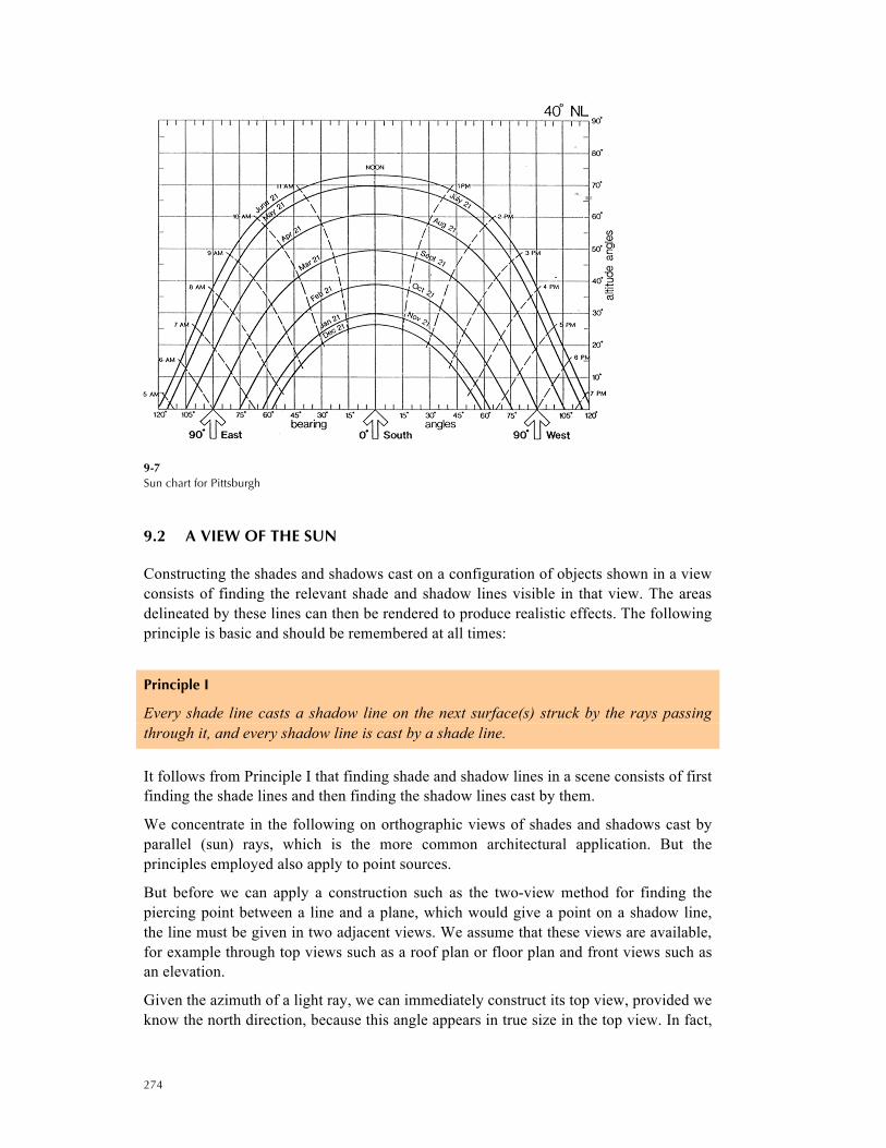
The altitude is sometimes also called the slope of the ray. Instead of the azimuth, the bearing of the ray may be given, which may be measured from a different reference line (see Figure 8.7). Azimuth and altitude change for the sun’s rays at the geographical latitude of the location, the day of the year, and the hour of the day. These figures can be looked up for specific latitudes; the example shown in Figure 8.7 is for the latitude of Pittsburgh. Sun-charts for other latitudes can be obtained from the University of Oregon’s Solar Radiation Monitoring Laboratory2.
2 http://solardat.uoregon.edu/SunChartProgram.html
ground plane
North
azimuth
a light ray
altitude
274
9-7 Sun chart for Pittsburgh
9.2 A VIEW OF THE SUN
Constructing the shades and shadows cast on a configuration of objects shown in a view consists of finding the relevant shade and shadow lines visible in that view. The areas delineated by these lines can then be rendered to produce realistic effects. The following principle is basic and should be remembered at all times:
Principle I
Every shade line casts a shadow line on the next surface(s) struck by the rays passing through it, and every shadow line is cast by a shade line.
It follows from Principle I that finding shade and shadow lines in a scene consists of first finding the shade lines and then finding the shadow lines cast by them.
We concentrate in the following on orthographic views of shades and shadows cast by parallel (sun) rays, which is the more common architectural application. But the principles employed also apply to point sources.
But before we can apply a construction such as the two-view method for finding the piercing point between a line and a plane, which would give a point on a shadow line, the line must be given in two adjacent views. We assume that these views are available, for example through top views such as a roof plan or floor plan and front views such as an elevation.
Given the azimuth of a light ray, we can immediately construct its top view, provided we know the north direction, because this angle appears in true size in the top view. In fact,

275
any line forming an angle the size of the azimuth with the north direction is the top view of a light ray because all of these rays are parallel to each other.
But this is hardly ever true for a given altitude angle: it normally does not appear in true size in a given elevation because the picture plane of that view is usually not parallel to the rays (if it were, we could not see any shadows cast on planes perpendicular to the picture plane). It is therefore advisable to start by finding the altitude in elevation for an arbitrary ray, after which it can be used for all the other rays. This can be done using the method of rotation (Chapter 7). We repeat the construction here.
Construction 9-1 Top and front views of a sun’s ray
Given azimuth a, and altitude b for a family of parallel light rays, find the top and front views of a ray l in the family.
There are three steps:
1. Draw the ray in the top view at an angle, α, from the direction of North. Select two points on the ray, X and Y, where Y pierces some horizontal plane that appears in edge view in f (in Figure 9-8, this plane is assumed to be the ground plane)
2. Draw a horizontal line through X. X is assumed to lie on the folding line and draw a circular arc with center X and radius XY. This arc intersects the horizontal line at A.
3. Project A and Y onto the edge view in f. Draw the ray r from Af that forms angle β with the edge view. This ray intersects the projection line from X at Xf. The ray through Xf and Yf is the front view of the ray. l forms angle γ with the ground plane, which is common to all rays in the front view.
9-8 Constructing the top and
front view of a light ray
γground plane
front
top
β
α
North
X
AY
A
Y
X

276
Given a ray in top and front views, we can draw the view of any parallel ray through a given point in either view by drawing a line through the point parallel to the given ray.
Architectural Convention
Where shadows are used more to give a drawing depth than employed to produce a realistic view for a specific time and day, it is usual to work with rays forming a 45° angle in both top and front views.
This is the general convention adopted for example in the quoted text by McGoodwin. It is nevertheless useful to retain some sense of the implications of the images created. Realistic views that can be obtained with these angles in the Pittsburgh area range from SE to S if the light falls from the upper left to the lower right. The conditions shown change with the direction faced by the building from noon during February for a building facing SE to mid-after-noon in late August for a building facing S. If the light falls from the upper right to the lower left, the views range from S to SW and cover conditions from morning in late-August to a February noon.
9.3 PLANAR POLYGONS
When constructing shades and shadows cast by shapes bounded by planar polygons on planar polygons or planes, the following principle must be kept in mind:
Principle II
A planar polygon is either completely in shade or not in shade at all. Its shade line is thus identical to its boundary.
If not in shade, such a surface may nevertheless be darkened, either in its entirety or in portions, by shadows cast on it. The shade line on a non-planar surface may cut across the surface (see the cylinder in Figure 9-3).
The first step is to determine which polygons are in shade. This is normally obvious. In case of doubt, select a ray that pierces the plane of the polygon and determine its visibility in an appropriate view. If you find a view in which the ray is visible before it strikes the plane, the polygon is not in shade (principle II).
In a second step, the shadows cast by shaded polygons can generally be found by constructing the piercing points of selected rays through the shade lines of the darkened polygons with the respective planes. This is demonstrated in the following examples.
9.1.5 Building with a Mansard roof
Figure 9-9 shows the top and front view of a building with a Mansard roof and a ray, l. The problem is to find the shades and shadows cast by light rays parallel to l on the ground plane.

277
9-9 Building with a Mansard roof
– problem statement
Clearly, the back and right walls of the building are in shade, and will cast shadows. In order to determine if roof surfaces are also in shade and thus cast shadows, we determine if a light ray through A, a point on the upper edge of surface a, disappears underneath the surface after striking it at A (in which case the surface a would be illuminated) or continues above the surface (in which case it would be shaded). Applying the visibility test between the ray and the lower ridge shows that roof plane a is shaded. In a similar way, we find that polygon b and the other roof polygons are lit.
9-10 Building with a Mansard roof
– determining shade lines
l
l
b
b
a
a
l
l
A
A

278
As shade lines of the shaded polygons are composed of line segments and the shadows they cast under rays parallel to l and the ground plane can be viewed as a parallel projection on a plane, these segments cast shadow lines in the form of segments. The entire shadow line can then be constructed by finding the piercing points between lines through the corners of the polygons that are in shade. This is shown in Figure 9-11 explicitly for B, the shadow point cast by A. As the ground plane appears already in edge view in the front view, a simplified version of construction 6.5 can be used: we construct B as a piercing point directly in the front view and project it into the top view. If one remembers that parallelism is preserved by parallel projections between planes, only a few shadow points have to be cast from the rays themselves; readers are encouraged to go through Figure 9-11. Also shown are shadow lines cast by each of the shaded polygons. Observe that some of these will fall inside the shadow.
9-11 Building with a Mansard roof – shaded with shadows
b
a
b
a
l
l
A
A
B
B

279
9.1.6 Shades and shadows cast by a dormer
The task is to find the shade and shadow cast by a dormer on a roof under parallel light. The dormer and roof and a light ray, l, are given in top and front view (see Figure 9-12). The difference from the preceding example is that the roof plane is inclined and thus does not appear in edge view in the front or top views. This is a typical case where the cutting plane method (Construction 6-2 on page 66) comes in handy.
9-12
Shades and shadow cast by a dormer – problem statement
The right roof surface and side of the dormer are shaded (this is clear from the front view where both surfaces appear in EV). The right roof surface can therefore immediately be shaded in the top view. See Figure 9-14.
9-13 Shades and shadow cast by a dormer
– shaded areas and shade lines
l
l
C
B
A
E
A,E

280
The problem is now to determine the shadow line cast on the main roof by the shade lines of the shaded surfaces. The first point constructed in Figure 8.14 is the piercing point, D, between the main roof and the ray through the peak of the dormer, A. The two-view method is applied using a cutting plane through the ray in the top view; the intersection in the front view between the trace of the cutting plane and the ray yields D in that view, from where it is projected into the top view. Connecting D with E, the piercing point of the dormer ridge with the main roof, gives the shadow line cast by the dormer ridge.
9-14 Shades and shadow cast by a dormer
The piercing point F of the ray through point B on the front of the dormer is found by using again a cutting plane through the ray in the top view. Its trace must be parallel to the trace through A and must pass through C in the front view; the trace in the front view can thus be found immediately and yields F in both views. Connecting F with D gives the shadow line cast by the front edge of the dormer roof. The rays through the edge belong to the same cutting plane and must therefore pierce the roof at the trace. Thus, connecting C and F completes the shadow line in both views.
If more than one surface is shadowed by an object, it is often helpful to cast shade points from important points into the larger plane to which a surface belongs even if the surface itself does not exist at the projected point; this point might be needed to construct accurately the shadow line on the surface. The next example makes use of this.
l
D
F
B,CA
B
F
D
C
E
A,E

281
9.1.7 Shadow cast by a dormer onto a Mansard roof
9-15 Shade and shadow cast by a dormer onto a
Mansard roof — problem statement
As in the previous example, the piercing point of the ray through A with the upper roof gives the shadow line cast by the dormer ridge. The shadow cast by the edge does not fall completely on the upper roof; but it is convenient to find the piercing point, F, of the edge with the plane of the upper roof in the front view. The shadow line leaves the upper roof at the intersection point, G, of the line through F and D with the edge between the upper and lower roof in the front view, from where it can be projected into the top view. The piercing point, H, of the ray through B with the lower roof can be found using the same cutting plane. Connecting H with both C and G completes the shadow line.
9-16 Shade and shadow cast by a dormer onto a
Mansard roof
l
C
B
A B,C
E
A,E
A, E
l
B,C
D
H
D
BH
G
GF
C
A
E

282
9.4 CURVED SURFACES
Curved surfaces usually require special techniques, the most useful of which are demonstrated in the following examples. In all of these, the following principle is at work:
Principle III
The shade line of a curved surface is made up of points where rays tangent to the surface meet the surface. For the most common curved surfaces, cylinders, cones and spheres, the shade line is the sum of all such points.
Circles play an important part in many cases. Because of the properties of a parallel projection of a plane on a parallel plane, a circular shade line casts a circular shadow under parallel light on any surface parallel to the plane that contains the circle. To create the shadow line, one only has to project the center of the circle into the plane by the ray through the center and draw a circle about the center with the same radius. This produces very quickly, together with principle II, the shades and shadows for the cylinder shown in Figure 9-17.
9-17 Shade and shadow cast by a cylinder (left) problem statement (right) solution

283
9.1.8 Stacked cylinders
9-18 Shade and shadows cast by stacked cylinders
Figure 9-18 shows the shades and shadows cast by stacked cylinders. Note how to generate the shadow cast by the cylinders above the ground plane on the ground plane. To generate the shadow line cast by the overhanging cylinder on the cylinder below, cutting planes parallel to the light rays are used to generate a sufficient number of points on the shadow line.

284
9-19 An illustration from McGoodwin’s book showing stacked cylinders

285
9.1.9 Right circular cone
Figure 8.20 shows the shade and shadow cast by a right circular cone on the ground plane. All that is needed is to project the shadow of the apex into the ground plane and to draw the tangents to the cone in this plane through the projected apex; these tangents define the shadow line cast by the cone. The shade line of the cone results from connecting the tangent points with the apex in both top and front views.
9-20 Shade and shadows cast by a right circular cone
Other variations are also illustrated in Figures 9-21, 9-22 and 9-23. For example, if the shadow is interrupted by a vertical wall, we determine the piercing points on the ground of the light rays as well as the piercing point of the light ray from the vertex onto the vertical plane. If the vertical wall is curved, for example, a cylindrical surface, then we find selected points on the shade line and project those to find appropriate shadow points on the wall and join these a smooth curve. Note that in these two cases, part of the shadow will be visible in the front elevation.
Figure 9-22 illustrates shadows of a cone onto another cone as well as the shadows cast by a truncated cone. In both case appropriate shade points are selected from shadow points are determined that pierce the appropriate surfaces.
Figure 9-23 illustrates two variations of shadows cast by a cone on a berm, which is piece of sloping ground that separates a ground at approximately the same elevation.

286
9-21 Shade and shadows cast by a right circular cone on vertical walls: (left) flat (below) curved walls
edge view of a vertical plane
edge view of acurved vertical plane

287
9-22 Shade and shadows cast by a right circular cone (above) onto another cone; (right) which is truncated

288
9-23 Shade and shadows cast by a right circular cone with variations of a berm
A berm is a mound of earth with sloping sides that is located between areas of approximately the same elevation

289
9.1.10 Cone and prism
Figure 9-24 shows shades and shadows cast by a cone and prism on each other and the ground plane. The cone casts shadows on different planes, and the construction shown in Figure 9-20 has to be repeated for each plane as demonstrated below.
9-24 Shade and shadows cast by a right circular cone placed on top of a prism

290
9.1.11 Sphere
Finding the shades and shadows cast by double-curved surfaces is a little more complicated. We demonstrate a fast method for spheres illustrated in Figure 9-26. This method relies on the following facts:
• The shade line of a sphere under parallel light is a circle on a plane through the center of the sphere normal to the rays and has the same radius as the sphere
• This shade line appears as an ellipse in views, except when the picture plane is parallel to the circle, in which case the circle appears in normal view, i.e. in true size, or when the picture plane is parallel to the rays, in which case the circle appears in edge view perpendicular to the rays
• When the shade line appears as an ellipse, its center is always the center of the sphere, its minor axis is parallel to the rays and its major axis is perpendicular to the rays with a length equal to the diameter of the sphere.
9-25 Shades and shadows cast by a sphere – problem statement
The latter facts can be used to draw an approximate ellipse quickly as shown in Figure 9-26. The major axes are determined by connecting points A and B in the front view and D and E in the top view where the rays are tangent to the sphere. D and E must lie on the equator and can thus be projected directly into the front view on a horizontal through the center, C. Similarly, A and B can be projected into the top view on a horizontal line through the center. This gives the major axis and two additional points in each view from which the entire ellipse can be approximated, for example with the help of a

291
template. This will suffice in many applications. The literature gives special constructions that allow the minor axis to be constructed accurately.
9-26 Shades and shadows cast by a sphere
The shadow line in the top view will also be an ellipse whose center F is the shadow point of C. The minor axis is parallel to and of the same length as the major axis of the shade ellipse. The major axis is determined by the shadow of point G, H (and its reflection about the major axis). Again, these points can be approximated or constructed accurately.
For other special cases that occur or occurred frequently in practice, the literature provides again special constructions, which may be quite elegant, if intricate. Figure 9-27 shows, as an example, the construction of the shadow line for a circular niche with a spherical head from McGoodwin’s text.
H
H
G
F
G
D
E
D
BA
A
B
C
C

292
9-27 A plate from McGoodwin’s book illustrating a circular niche