SGP4 PROPAGATION PROGRAM DESIGN AND VALIDATION
32
UNIVERSITY OF WATERLOO Faculty of Engineering Department of Electrical and Computer Engineering SGP4 PROPAGATION PROGRAM DESIGN AND VALIDATION Canadian Space Agency 6767 route de l'Aéroport Saint-Hubert, QC, J3Y 8Y9 (450) 926-4441 Prepared by Ilia V. Baranov ID #20298374 [email protected] 1A Electrical Engineering April 13, 2009
Transcript of SGP4 PROPAGATION PROGRAM DESIGN AND VALIDATION

UNIVERSITY OF WATERLOO
Faculty of Engineering
Department of Electrical and Computer Engineering
SGP4 PROPAGATION PROGRAM
DESIGN AND VALIDATION
Canadian Space Agency
6767 route de l'Aéroport
Saint-Hubert, QC, J3Y 8Y9
(450) 926-4441
Prepared by
Ilia V. Baranov
ID #20298374
1A Electrical Engineering
April 13, 2009
Ilia V. Baranov
70 Peninsula Cres
Richmond Hill, ON L4S 1Z5
April 13, 2009
Manoj Sachdev, Chair
Electrical and Computer Engineering
University of Waterloo
Waterloo, Ontario
N2L 3G1
Dear Sir, Please find enclosed the report pertaining to the completion of the WKRPT 100 course. This report, titled "SGP4 Propagation Program Design and Validation", was prepared as my 1A Work Report for the Canadian Space Agency. The purpose of this report is to detail the design, implementation and validation of a satellite orbital modelling program. The Canadian Space Agency is a governmental organization charged with the peaceful, beneficial use of space and with ensuring the proper distribution of funds associated with space research, engineering and public education.
The Telemetry, Tracking and Control team, in which I was employed, is lead in part by Mr. Marc Sauvageau, P. Eng., and is responsible for all communications with Canadian and partner satellites.
I would like to thank Marc Sauvageau, my supervisor, for guidance and resources throughout the work term. I would also like to thank my co-worker Tolga Tezel for support in some of the mathematical theory behind satellite propagation.
I hereby confirm that I have received no further help other than what is mentioned above in writing this report. I also confirm this report has not been previously submitted for academic credit at this or any other academic institution.
Sincerely,
________________________________
Ilia Baranov, 20298374

iii
Contributions
The Satellite Operations division is responsible for all matters concerning
Canadian satellites and partnerships with satellite divisions from other space agencies.
My specific assignment was with the Telemetry, Tracking and Control team, a sub-
division of Satellite Operations. This is a relatively small team consisting of six engineers
and six technicians responsible for maintaining communication with satellites and
maintaining and upgrading the communications equipment in Canadian ground stations.
The main ground station is located at the Canadian Space Agency (CSA) headquarters in
Saint-Hubert, Quebec. There, the systems pertaining to satellite communications are kept.
These include the main antenna, signal modulation and demodulation equipment, and so
on. A secondary station is located in Saskatoon, along with other support stations located
all over the world.
The team’s assigned task is to ensure proper communication between satellites
and Canadian ground stations. This task is subdivided into three sections; Telemetry,
Tracking and Control (TT&C). Telemetry consists of receiving data from a satellite
pertaining to its physical state, such as orientation, system health, and so on. Tracking
consists of locating and predicting the position of a satellite using real time ranging and
mathematical models respectively. Lastly, Control consists of transmitting commands
back to the satellite, such as orientation commands, orbital changes and so on. The senior
engineers on the team also consult on future satellite projects with the aim to ensure
compatibility and functionality of the communication systems.
My tasks where mostly related to Tracking of satellites and launch vehicles. My
first task was the construction, software installation and integration of a computer system
capable of tracking European Space Agency (ESA) launch vehicles. This is accomplished
by using a piece of software written to take in current coordinates of a launch vehicle,
then translate them into pointing angles for the Saint-Hubert station antenna. The
coordinates are generated by the launch facility, sent via the internet, then decoded and
used to point the antenna at the expected location of the launch vehicle. This task
provided me with some of the mathematical knowledge needed to complete my next and
largest task. This next task consisted of writing updated software to predict the orbital

iv
position of a satellite based on a Two-Line Element (TLE) file generated by either the
CSA or any other space agency. This class of orbital prediction programs are known as
Simplified General Perturbations Satellite Orbit Model 4 (SGP4) programs. In addition,
suitable interface program creation and validation of the SGP4 output where part of this
task. This new SGP4 propagation software is known as IVB SGP4.
The relationship between this report and my job is the documentation of the
design, implementation and validation provided here. This information will provide a
guide to future programmers and engineers in using and updating the software. In
addition, explanation of design choices that may seem counterintuitive will be provided
here. Lastly, the detailed validation procedures and results provide evidence of the
software’s accuracy and provide a baseline for software performance. These results will
be useful in assessing the validity of future results and troubleshooting in case of program
error. On a personal level of development, this report has allowed me to develop
academic, analytical and communicative abilities. In the academic field, knowledge
gained in programming, mathematics and systems design will greatly aid in furthering
my studies in electrical engineering. This report, and the work term in general, have
provided me with a head start on academic material before it is introduced within school.
On the analytical side, this report allows for further development of skills introduced in
courses such as PDENG 15 and GENE 167. These skills included problem solving,
making defensible recommendations and engineering analysis. These and most other
introduced skills are presented throughout the report. Additionally, they proved essential
in a workplace such as the CSA. Lastly, the report has allowed further development of
communicative skills. The strict adherence to format and content requirements is similar
to actual workplace experience. This, along with feedback provided for this report allows
for development of writing techniques. In general, this report serves as documentation to
the CSA of the software and as a permanent record of my work term.
In the broader scheme of things, my task of developing IVB SGP4 and interface
software was a core component of future systems within TT&C. The new program will
replace currently used, commercially purchased libraries that are expensive and slightly
outdated. IVB SGP4 provides an open source, higher accuracy solution to orbital
prediction and antenna tracking. Also, the ability of the program to provide multiple

v
forms of output that are custom tailored to the needs of TT&C allows it to be used in
station automation. Station automation is a proposal to convert most of the current
manual satellite communication operations to computer-controlled systems. This will free
human resources for other, non-repetitive tasks. Therefore, IVB SGP4 plays an important
role in upgrading current systems and planning for future station automation.

vi
Summary
The main purpose of this report is to detail the design, implementation and
validation of an updated satellite orbital prediction program known as IVB SGP4 for use
with TT&C stations operated by the CSA. The scope of this report is limited to the
specific program named above for use with the Saint-Hubert TT&C station, and station
equipment.
The major points covered in this document focus on the implementation of
theoretic SGP4 code to a useable program. In addition, the report details methods to
integrate the new code into the existing TT&C infrastructure and foreseeable limitations.
Lastly, this document examines the testing and validation procedures taken along with
the results obtained. These results indicate the validity of program output and dictate the
suitability of using the program in an operational environment.
The major conclusions in this report disclose the suitability of integrating IVB
SGP4 into existing systems. Firstly, needs analysis and design specification concludes
that the older propagation program is inefficient and should be replaced. Secondly, the
interface methods and design requirement compliance of the new program are judged to
be sufficient, allowing its integration into the operational environment. Lastly, the output
of the program is judged sufficiently accurate and consistent for use within the
operational environment over normal lengths of time.
The major recommendations in this report are focused on the implementation of
IVB SGP4 in the operational TT&C system. The first recommendation details the
changes required to the operational system to accommodate the new propagation
program. In addition, recommendations pertaining to future upgrading and possible uses
for the code are detailed, including station automation. Lastly, it is recommended that
sufficient time and human resources be invested to continue the integration and validation
of the new program.

vii
Table of Contents
Contributions .......................................................................................................................................... iii
Summary ................................................................................................................................................ vi
List of Figures ........................................................................................................................................ viii
List of Tables ........................................................................................................................................... ix
1 Introduction ................................................................................................................................ 1
1.1 Background ................................................................................................................................. 1
1.2 Scope .......................................................................................................................................... 2
1.3 Outline ........................................................................................................................................ 2
2 Technical Overview ..................................................................................................................... 3
2.1 SGP4 Propagation Theory ............................................................................................................ 3
2.2 Satellite Communication Requirements ....................................................................................... 5
3 Program Design and Implementation .......................................................................................... 6
3.1 C++ Core Propagation Modification ............................................................................................. 6
3.1.1 Challenges and Limitations .......................................................................................................... 7
4 Testing and Validation ................................................................................................................. 9
4.1 Methodology ............................................................................................................................... 9
4.2 Results .......................................................................................................................................10
5 Conclusions ................................................................................................................................14
6 Recommendations .....................................................................................................................14
Glossary .................................................................................................................................................16
References .............................................................................................................................................17
Appendix A – TLE Format .......................................................................................................................18
Appendix B – Output Format..................................................................................................................19
Appendix C – Data Comparison Graphs ..................................................................................................22

viii
List of Figures
Figure 1: Sample TLE for Radarsat-1 ............................................................................................ 3
Figure 2: ECI TEME Reference Frame ........................................................................................... 4
Figure 3: Region of Visibility ........................................................................................................ 5
Figure 4: 2D projection of two passes.......................................................................................... 7
Figure 5: Y-axis Coordinate comparison..................................................................................... 10
Figure 6: Y Coordinate Residual ................................................................................................. 10
Figure 7: X coordinate propagation over 4 days......................................................................... 11
Figure 8: Solar Azimuth comparison .......................................................................................... 12
Figure 9: Solar Azimuth Residual ............................................................................................... 12
Figure 10: Elevation plot from STK, IVB and record .................................................................... 13
Figure 11: Elevation Residual of STK and IVB ............................................................................. 13
Figure 12: Close up of Y-axis residual on Orbit 69419 ................................................................ 22
Figure 13: X-axis coordinates over 4 days .................................................................................. 22
Figure 14: Full Elevation plot from STK, IVB and recorded ......................................................... 23
ix
List of Tables
Table 1: Timestamp Offset in the original code ........................................................................... 8
Table 2: TLE Data format ........................................................................................................... 18
Table 3: TLE Line 1 details ......................................................................................................... 18
Table 4: TLE Line 2 details ......................................................................................................... 18
Table 5: Example Pass List Strings.............................................................................................. 19
Table 6: Example Full Data/Visible Data Strings ......................................................................... 21
Table 7: Example Solar Data Strings .......................................................................................... 21
1
1 Introduction
The CSA TT&C division handles communication with most Canadian
government satellites along with several European satellites. This task requires the
effective tracking of the satellites as they orbit in space. This tracking allows for the
proper orientation of the communications antenna, known as the antenna pointing angle.
This pointing angle is very important to TT&C because it has the largest effect on signal
strength, thus it must be very accurate in order to provide the highest signal to noise ratio.
The prediction of where a satellite is in three-dimensional space is used to generate the
pointing angles for the antenna. In this section, Background information is provided as a
baseline for the report. In addition, the Scope section details the intended report subject
and describes limitations on the depth of the report. Lastly, the Outline section provides
an overview of the topics covered in each section.
1.1 Background
The TT&C division used a commercially written SGP4 propagator written as an
ActiveX™ library. This approach had several downfalls. The first is that the library was a
purchased product, leading to recurring licensing fees for the department. In addition, the
source code for the library was not available, limiting the customization available to the
department. Thirdly, the code did not respond well to being called by multiple programs
at the same time. Lastly, the code was outdated and did not reflect the changes suggested
by Revisiting Spacetrack Report #3 [1]. The decision was made to create an updated
version of the propagator in-house, based on the source code and findings detailed in the
above report. This new program had to be compared to results obtained by ActiveX™
and STK™. STK™ is a professional propagation program that is used by the planning
department. Lastly, the output was also compared to real world pointing angles recorded
during a pass.
2
1.2 Scope
The purpose of this report is to detail the design and validation of IVB SGP4, an
orbital propagation program. This report is intended for use as a reference by an educated
audience with a technical specialization. Included are the design specifications and
constraints. In addition, the testing method along with results obtained and improvements
performed are included. The report is limited to discussing the design in the context of
modifying the C++ code available in Revisiting Spacetrack Report #3 [1] along with
designing the interface to the Labview™ operational environment. The validation portion
is limited to the above-indicated comparisons along with comparison to the operational
system scheduling program.
1.3 Outline
This report records the design, implementation and validation of IVB SGP4 in
order to provide a reference for future projects of a similar nature. Section 2 provides a
brief overview of technical background to the project along with requirements placed on
the program. In essence, this section details the design component of the report. Section 3
discusses the implementation of the code and some challenges encountered along the
way. Section 4 reviews the validation procedure and the results obtained. Section 5
discuses the conclusions that can be drawn from this report, based on the information.
Lastly, Section 6 presents recommendations for action to take pertaining to
implementation of IVB SGP4 in the operational system.
3
2 Technical Overview
2.1 SGP4 Propagation Theory
While Newton's Law of Universal Gravitation works perfectly in the classroom,
such simplified physics does not function when predicting the orbital path of satellites in
near earth orbit. There exist a few reasons for this, first of which being that neither the
earth nor the satellite are point masses. The basis of satellite orbital propagation is
Keplerian orbit elements. These orbit characteristics define the orbital orientation, shape,
speed of orbit and the last known position of the satellite [2]. These can be used to
generate a rough estimation of a satellite’s position; however, such predictions will fail to
reflect reality for extended periods due to disturbances, known as perturbations, in the
orbit. These disturbances include atmospheric drag and lunar gravitational pull to name a
few. The need for accurate orbital prediction at the dawn of the space age lead to the
development of the Simplified General Perturbations model in 1970 [1]. This model was
later improved into Simplified General Perturbations model 4 (SGP4) in 1980 [1]. This
new model is thought to be as close as possible to currently used NORAD orbital models,
the details of which are not published. However, a few corrections where still required to
obtain an operationally reliable orbital propagation model. These changes were listed in
[1].
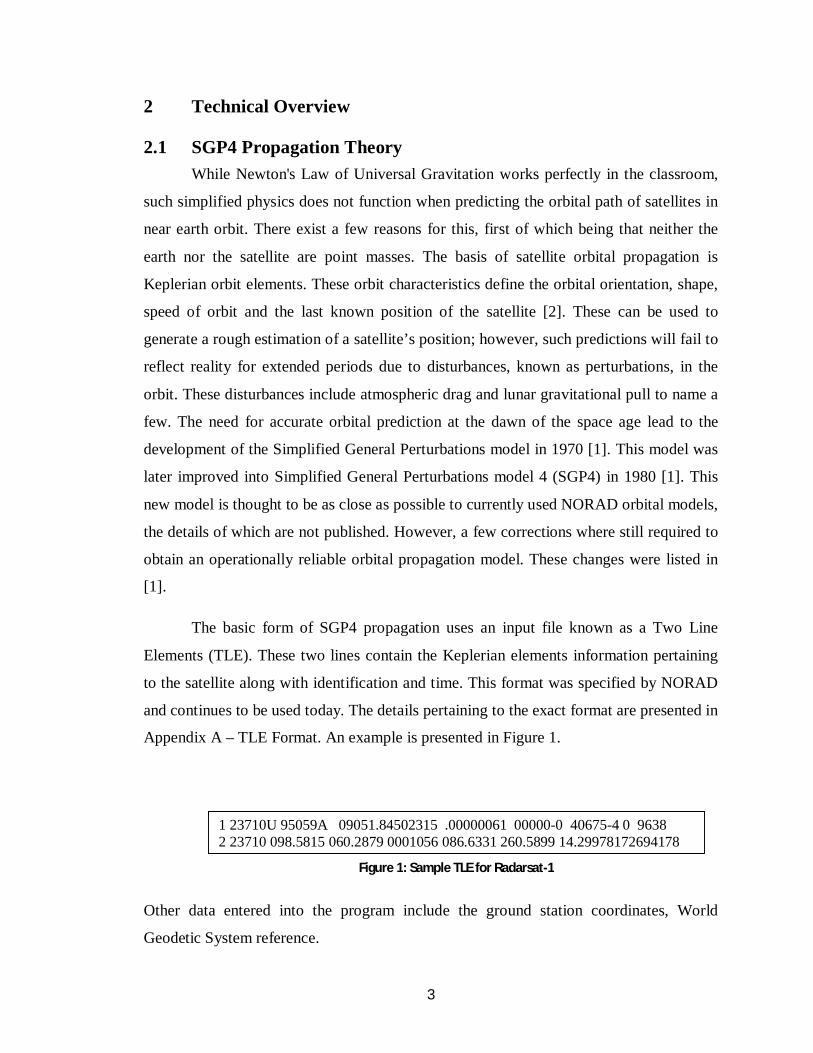
The basic form of SGP4 propagation uses an input file known as a Two Line
Elements (TLE). These two lines contain the Keplerian elements information pertaining
to the satellite along with identification and time. This format was specified by NORAD
and continues to be used today. The details pertaining to the exact format are presented in
Appendix A – TLE Format. An example is presented in Figure 1.
Other data entered into the program include the ground station coordinates, World
Geodetic System reference.
1 23710U 95059A 09051.84502315 .00000061 00000-0 40675-4 0 9638 2 23710 098.5815 060.2879 0001056 086.6331 260.5899 14.29978172694178
Figure 1: Sample TLE for Radarsat-1
4
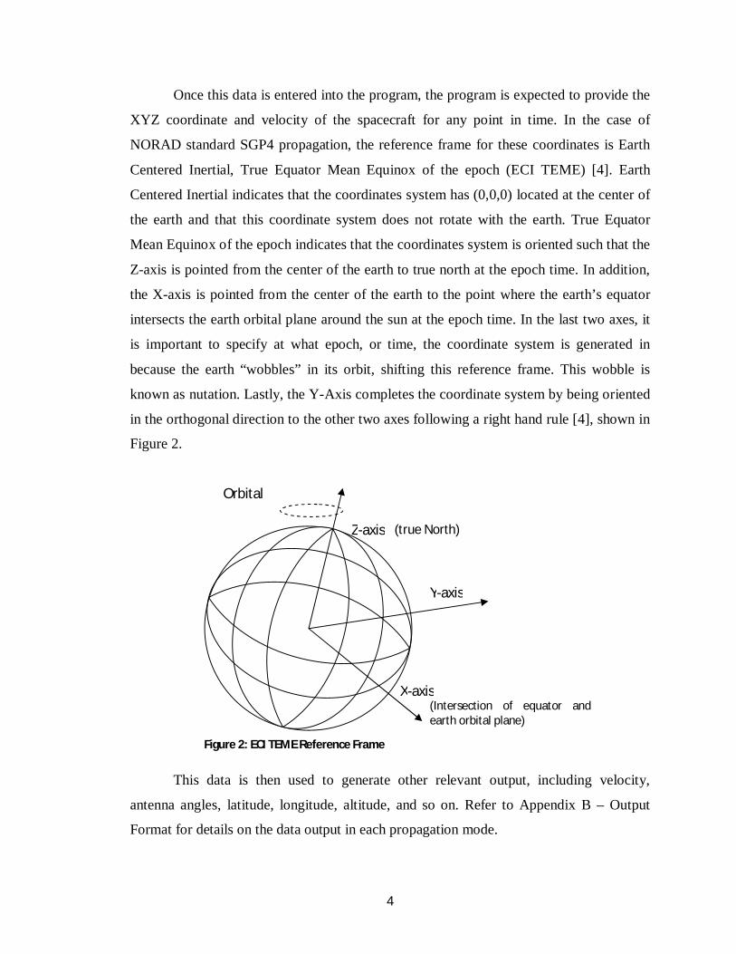
Once this data is entered into the program, the program is expected to provide the
XYZ coordinate and velocity of the spacecraft for any point in time. In the case of
NORAD standard SGP4 propagation, the reference frame for these coordinates is Earth
Centered Inertial, True Equator Mean Equinox of the epoch (ECI TEME) [4]. Earth
Centered Inertial indicates that the coordinates system has (0,0,0) located at the center of
the earth and that this coordinate system does not rotate with the earth. True Equator
Mean Equinox of the epoch indicates that the coordinates system is oriented such that the
Z-axis is pointed from the center of the earth to true north at the epoch time. In addition,
the X-axis is pointed from the center of the earth to the point where the earth’s equator
intersects the earth orbital plane around the sun at the epoch time. In the last two axes, it
is important to specify at what epoch, or time, the coordinate system is generated in
because the earth “wobbles” in its orbit, shifting this reference frame. This wobble is
known as nutation. Lastly, the Y-Axis completes the coordinate system by being oriented
in the orthogonal direction to the other two axes following a right hand rule [4], shown in
Figure 2.
This data is then used to generate other relevant output, including velocity,
antenna angles, latitude, longitude, altitude, and so on. Refer to Appendix B – Output
Format for details on the data output in each propagation mode.
Z-axis
X-axis
Y-axis
Orbital
nutation
Figure 2: ECI TEME Reference Frame
(true North)
(Intersection of equator and earth orbital plane)

5
2.2 Satellite Communication Requirements
Satellite communication with Low Earth Orbit (LEO) satellites involves accurate
timing and planning. Because the satellite is in view for only a limited amount of time,
each pass is crucial to scientific research and has a large monetary value. Because of this,
the TT&C system must be extremely reliable. This requirement places severe constraints
on communication and tracking methods, some of which are listed here.
The first requirement of the IVB SGP4 was accurate predictions. The spacecraft must be
targeted by the antenna with an accuracy of ± 0.4 degrees at all time. This region is
known as the Region of Visibility, as the signal strength drops quickly outside this
region. The loss of signal strength is known as attenuation, and a misalignment of 0.4
degrees would cause an attenuation of 3dBm. This attenuation is represented in Figure 3.
The second requirement was the ability to provide data in a variety of forms. The
data input and output requirements included full data, visible only, pass list and solar.
This requirement was used in the design of data output format, the details of which are
presented in Appendix B – Output Format. More information on data output types is
presented in section 3.1.
3dbm signal
attenuation
600 – 1200 km
0.8⁰
Figure 3: Region of Visibility

6
Another requirement was to provide the ability for multiple applications to obtain
data from the propagator simultaneously. The ActiveX™ library was unable to provide
this functionality and caused frequent crashes.
The last major design constraint was speed of execution. The code must be able to
generate an entire overhead pass within a second with reasonable accuracy. This entails
the use of recursive programming methods, search algorithms, and optimization of
reading and writing operations using buffers.
Although the ActiveX™ library used previously was fast, it was unable to fulfill
most of the other requirements, along with being expensive and un-modifiable. The
conclusion to this was that a new SGP4 propagator was required.
3 Program Design and Implementation
3.1 C++ Core Propagation Modification
The core C++ code presented in Revisiting Spacetrack Report #3 [1] provided a
baseline for creating an SGP4 propagator. This code presents most of the required
algorithms to accomplish propagation, however it was meant to be an academic
demonstration of the principle, not an operational program. Due to this, several
modifications were required to render the program fully usable. These changes fall into
two categories: feature addition and functionality modification.
Feature addition to the program entailed adding functions and outputs not present
in the original code. The first addition was enabling variable time steps. This allows the
user to specify the time interval between adjacent data lines. Another addition was the
division of output formats into four types: Full Data, Visible Data, Pass List and Solar.
Full Data format outputs all available data at each time step from start time to stop time.
Visible Data is similar to Full Data except it will only output data whenever the satellite
is visible from the station in question. Pass List format outputs only the rough
information pertaining to multiple orbits over the requested time period. Lastly, Solar
Format outputs information pertaining to the sun’s position in the sky over the given time
period. This information is used to avoid facing the antenna directly into the sun. Another
major addition was the creation of a sub method to project XYZ coordinates onto a two
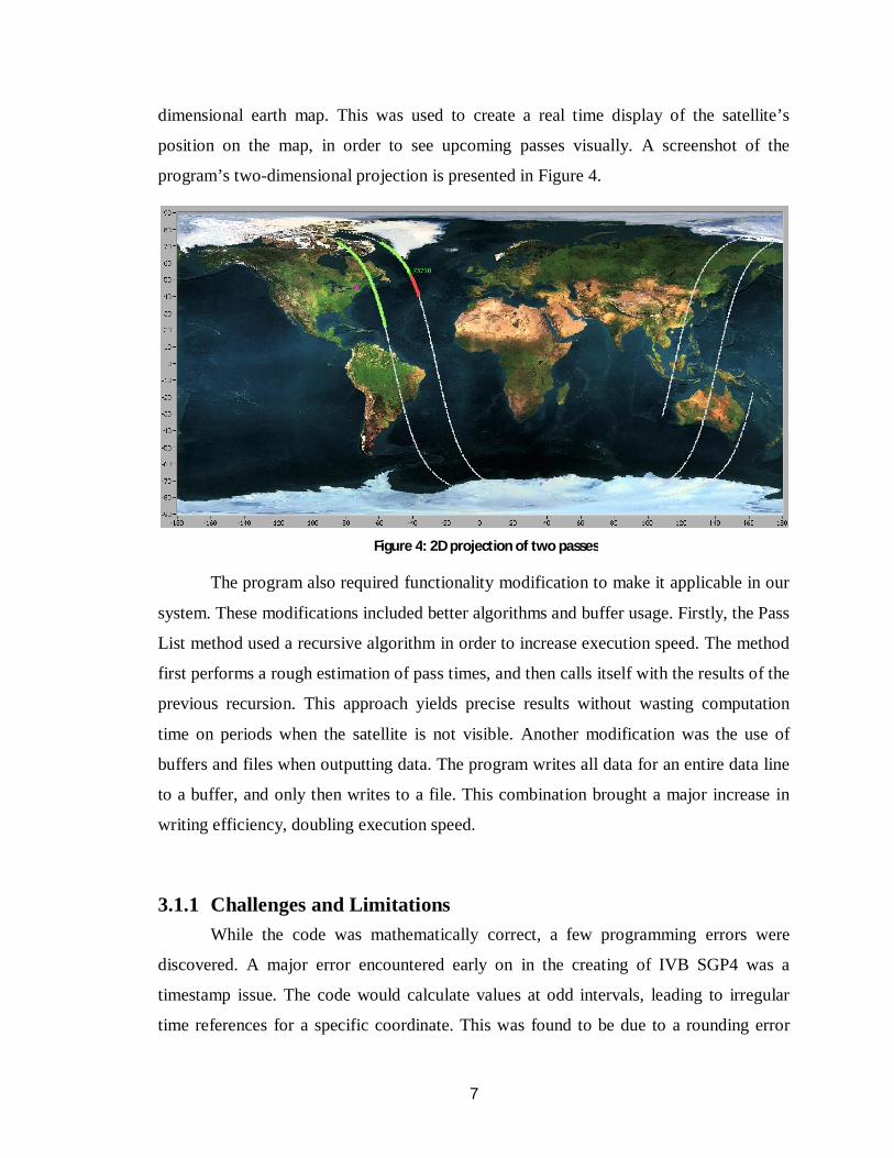
7
dimensional earth map. This was used to create a real time display of the satellite’s
position on the map, in order to see upcoming passes visually. A screenshot of the
program’s two-dimensional projection is presented in Figure 4.
The program also required functionality modification to make it applicable in our
system. These modifications included better algorithms and buffer usage. Firstly, the Pass
List method used a recursive algorithm in order to increase execution speed. The method
first performs a rough estimation of pass times, and then calls itself with the results of the
previous recursion. This approach yields precise results without wasting computation
time on periods when the satellite is not visible. Another modification was the use of
buffers and files when outputting data. The program writes all data for an entire data line
to a buffer, and only then writes to a file. This combination brought a major increase in
writing efficiency, doubling execution speed.
3.1.1 Challenges and Limitations
While the code was mathematically correct, a few programming errors were
discovered. A major error encountered early on in the creating of IVB SGP4 was a
timestamp issue. The code would calculate values at odd intervals, leading to irregular
time references for a specific coordinate. This was found to be due to a rounding error
Figure 4: 2D projection of two passes
8
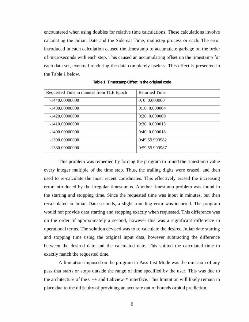
encountered when using doubles for relative time calculations. These calculations involve
calculating the Julian Date and the Sidereal Time, multistep process or each. The error
introduced in each calculation caused the timestamp to accumulate garbage on the order
of microseconds with each step. This caused an accumulating offset on the timestamp for
each data set, eventual rendering the data completely useless. This effect is presented in
the Table 1 below.
Table 1: Timestamp Offset in the original code
Requested Time in minutes from TLE Epoch Returned Time
-1440.00000000 0: 0: 0.000000
-1430.00000000 0:10: 0.000004
-1420.00000000 0:20: 0.000009
-1410.00000000 0:30: 0.000013
-1400.00000000 0:40: 0.000018
-1390.00000000 0:49:59.999982
-1380.00000000 0:59:59.999987
This problem was remedied by forcing the program to round the timestamp value
every integer multiple of the time step. Thus, the trailing digits were erased, and then
used to re-calculate the most recent coordinates. This effectively erased the increasing
error introduced by the irregular timestamps. Another timestamp problem was found in
the starting and stopping time. Since the requested time was input in minutes, but then
recalculated in Julian Date seconds, a slight rounding error was incurred. The program
would not provide data starting and stopping exactly when requested. This difference was
on the order of approximately a second, however this was a significant difference in
operational terms. The solution devised was to re-calculate the desired Julian date starting
and stopping time using the original input data, however subtracting the difference
between the desired date and the calculated date. This shifted the calculated time to
exactly match the requested time.
A limitation imposed on the program in Pass List Mode was the omission of any
pass that starts or stops outside the range of time specified by the user. This was due to
the architecture of the C++ and Labview™ interface. This limitation will likely remain in
place due to the difficulty of providing an accurate out of bounds orbital prediction.

9
Another limitation was that IVB SGP4, when compared to output from STK™
Version 8, was been shown to have an oscillating residual with an increasing error over
time. This error is under 0.07Km over 4 days for the XYZ coordinates. Due to this, Full
Data, Visible Data, and Solar Data of this program should not be utilized when generated
for a period exceeding ±5 days from the TLE Epoch Time. Pass List Data should
similarly not be used when exceeding 20 days. This limitation may be improved upon by
putting more work into the mathematic development; however, there was no need to
implement such a long-term prediction at the time.
The challenges presented in integrating the format and improving on the data
were numerous. However, the final program provided data in the proper format and was
easily integratable into the existing system. This leads to the conclusion that IVB SGP4
adheres to the design specifications sufficiently to be used in the operational system.
4 Testing and Validation
4.1 Methodology
The only failsafe way to check output data form IVB SGP4 was to compare the
results calculated to other, professionally used programs along with real world recorded
data. This was accomplished by the implementation of several Labview™ programs
designed to graph and compare the data. The raw XYZ coordinates were compared
between IVB SGP4 and STK™™ by AGI, which is another professional orbital
propagation program. The antenna azimuth and elevation data was also compared
between real life data, IVB SGP4 and STK™. The residual between the IVB SGP4 and
the other two methods where compared to verify for any systematic error or bias. Full
data, Visible data and Solar data where compared in this fashion, while Pass list was
compared against the scheduling software available in-house. A comparison between the
original SGP4 code and IVB SGP4 is also provided.
10
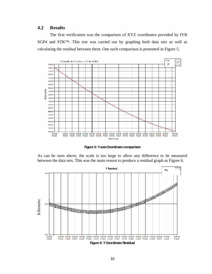
4.2 Results
The first verification was the comparison of XYZ coordinates provided by IVB
SGP4 and STK™. This test was carried out by graphing both data sets as well as
calculating the residual between them. One such comparison is presented in Figure 5.
Figure 5: Y-axis Coordinate comparison
As can be seen above, the scale is too large to allow any difference to be measured between the data sets. This was the main reason to produce a residual graph as Figure 6.
Figure 6: Y Coordinate Residual
Res
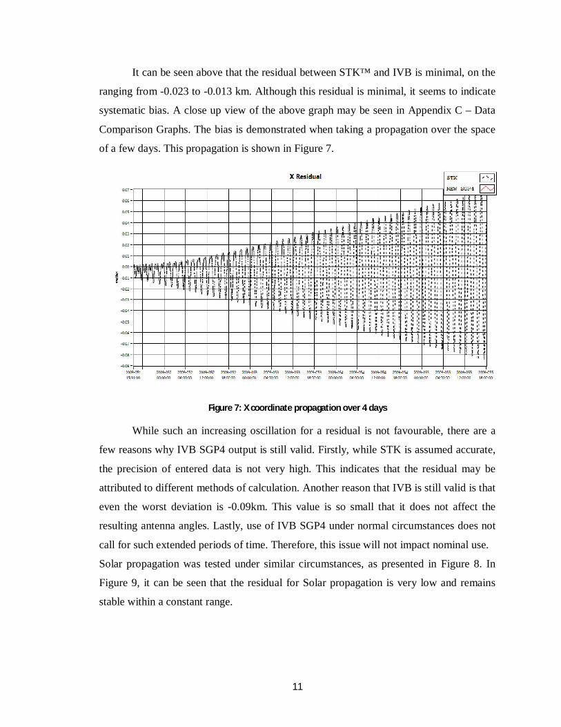
11
It can be seen above that the residual between STK™ and IVB is minimal, on the
ranging from -0.023 to -0.013 km. Although this residual is minimal, it seems to indicate
systematic bias. A close up view of the above graph may be seen in Appendix C – Data
Comparison Graphs. The bias is demonstrated when taking a propagation over the space
of a few days. This propagation is shown in Figure 7.
Figure 7: X coordinate propagation over 4 days
While such an increasing oscillation for a residual is not favourable, there are a
few reasons why IVB SGP4 output is still valid. Firstly, while STK is assumed accurate,
the precision of entered data is not very high. This indicates that the residual may be
attributed to different methods of calculation. Another reason that IVB is still valid is that
even the worst deviation is -0.09km. This value is so small that it does not affect the
resulting antenna angles. Lastly, use of IVB SGP4 under normal circumstances does not
call for such extended periods of time. Therefore, this issue will not impact nominal use.
Solar propagation was tested under similar circumstances, as presented in Figure 8. In
Figure 9, it can be seen that the residual for Solar propagation is very low and remains
stable within a constant range.

12
Figure 8: Solar Azimuth comparison
Figure 9: Solar Azimuth Residual
Lastly, the Azimuth, Elevation, Range and Range Rate were compared between
IVB SGP4, STK™ and real world results. This data was only available for one pass,
however the pass selected has a very high maximum elevation. A high maximum
elevation leads to the fastest pass speeds and highest rate of errors. Therefore, if a
propagation is accurate for a high pass, it should also be accurate for most lower passes
as well.
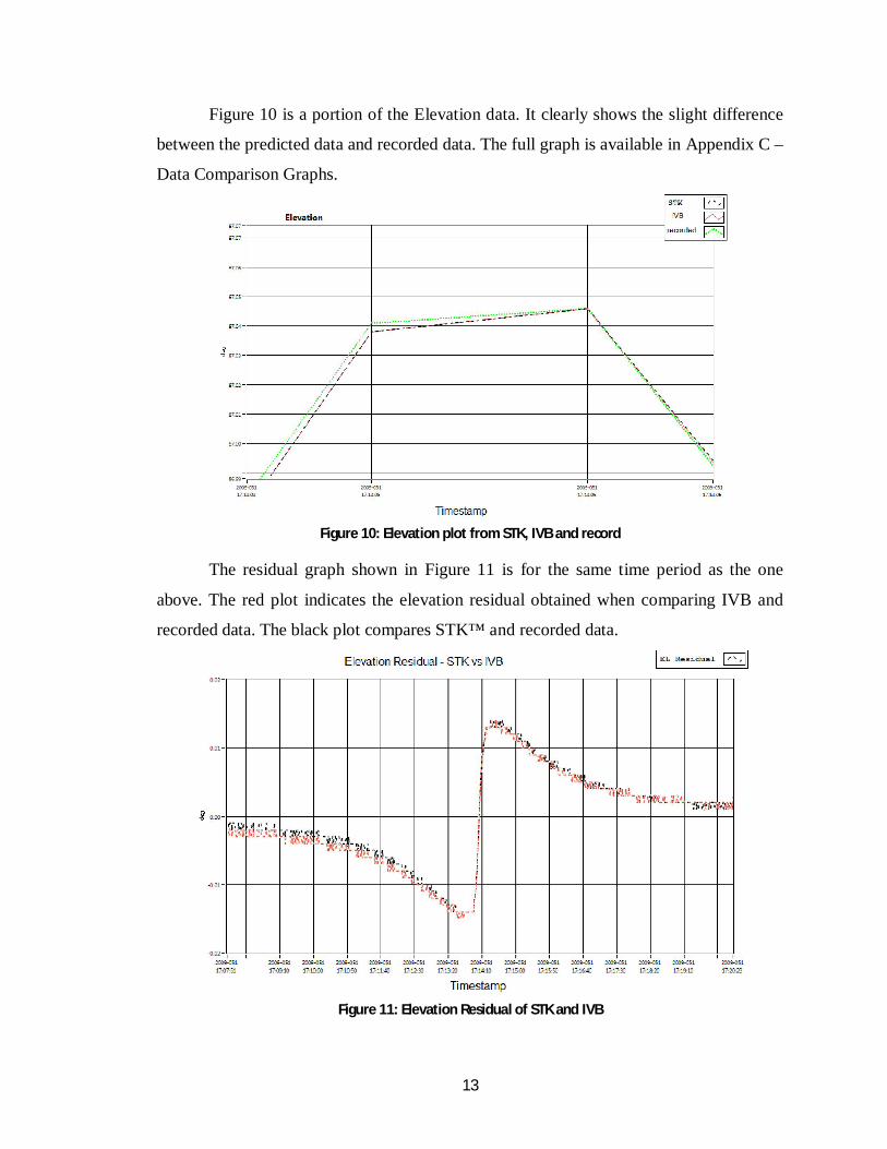
13
Figure 10 is a portion of the Elevation data. It clearly shows the slight difference
between the predicted data and recorded data. The full graph is available in Appendix C –
Data Comparison Graphs.
Figure 10: Elevation plot from STK, IVB and record
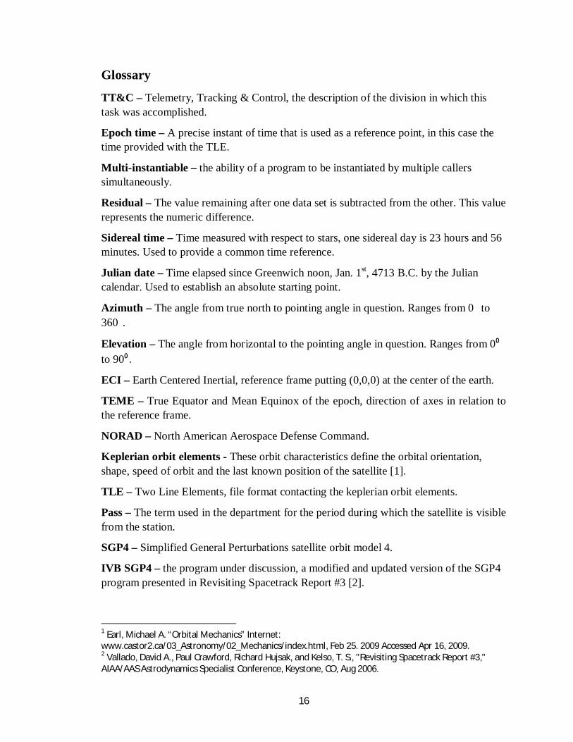
The residual graph shown in Figure 11 is for the same time period as the one
above. The red plot indicates the elevation residual obtained when comparing IVB and
recorded data. The black plot compares STK™ and recorded data.
Figure 11: Elevation Residual of STK and IVB

14
As has been shown in this section, IVB SGP4 clearly produces reasonably
accurate propagation and has the same characteristics as STK™, which is a professional
program. This, along with more extensive testing performed during the validation, leads
to the conclusion that IVB SGP4 is sufficiently accurate and consistent for use within the
operational environment over normal lengths of time.
5 Conclusions
In essence, this report concludes that IVB SGP4 is suitable for use in the TT&C
system. This conclusion is substantiated by the validation and design documentation
provided above. Section 2.2 concluded that a new SGP4 propagator was required and
described the requirements for one. Section 3 detailed the design and implementation,
ultimately concluding that the program satisfied all requirements. Lastly, in section 4, the
output of the program is shown to be accurate enough for use in the system and also
shown to match the real world data.
6 Recommendations
The first recommendation encompasses the changes necessary to the current
system in order to utilize the new system. The Labview™ interface programs should be
re-written to implement more parallel processing in order to take advantage of the multi-
instantiable nature of the code. In addition, the data input to the propagator has changed
and will need updating as well.
IVB SGP4 incorporates many more features than the previous propagation
solution. By having all of these features in the same program, station automation
becomes possible. Interface programs must be written to utilize the raw data provided by
IVB SGP4 in order to drive station systems such as the main antenna, converters, and so
on. The code must also be consistently verified against newer algorithms and odd-orbit
satellites. Doing so will ensure that the program remains up to date and will catch any
errors.

15
To accomplish all these tasks, human resources along with sufficient technical
support and time must be invested to further this project. If this project is not continued,
then the resources and expertise currently invested will go to waste. In addition, the
original problem will persist, causing more costs along the way. It is for this reason that
the final recommendation is for the immediate investment of the above mentioned
resources into the development of this project into an operational system.
16
Glossary
TT&C – Telemetry, Tracking & Control, the description of the division in which this
task was accomplished.
Epoch time – A precise instant of time that is used as a reference point, in this case the
time provided with the TLE.
Multi-instantiable – the ability of a program to be instantiated by multiple callers
simultaneously.
Residual – The value remaining after one data set is subtracted from the other. This value
represents the numeric difference.
Sidereal time – Time measured with respect to stars, one sidereal day is 23 hours and 56
minutes. Used to provide a common time reference.
Julian date – Time elapsed since Greenwich noon, Jan. 1st, 4713 B.C. by the Julian
calendar. Used to establish an absolute starting point.
Azimuth – The angle from true north to pointing angle in question. Ranges from 0⁰ to
360⁰.
Elevation – The angle from horizontal to the pointing angle in question. Ranges from 0⁰
to 90⁰.
ECI – Earth Centered Inertial, reference frame putting (0,0,0) at the center of the earth.
TEME – True Equator and Mean Equinox of the epoch, direction of axes in relation to
the reference frame.
NORAD – North American Aerospace Defense Command.
Keplerian orbit elements - These orbit characteristics define the orbital orientation,
shape, speed of orbit and the last known position of the satellite [1].
TLE – Two Line Elements, file format contacting the keplerian orbit elements.
Pass – The term used in the department for the period during which the satellite is visible
from the station.
SGP4 – Simplified General Perturbations satellite orbit model 4.
IVB SGP4 – the program under discussion, a modified and updated version of the SGP4
program presented in Revisiting Spacetrack Report #3 [2].
1 Earl, Michael A. “Orbital Mechanics” Internet: www.castor2.ca/03_Astronomy/02_Mechanics/index.html, Feb 25. 2009 Accessed Apr 16, 2009. 2 Vallado, David A., Paul Crawford, Richard Hujsak, and Kelso, T. S., "Revisiting Spacetrack Report #3," AIAA/AAS Astrodynamics Specialist Conference, Keystone, CO, Aug 2006.
17
References
[1] Vallado, David A., Paul Crawford, Richard Hujsak, and Kelso, T. S., "Revisiting
Spacetrack Report #3," AIAA/AAS Astrodynamics Specialist Conference, Keystone,
CO, Aug 2006.
[2] Earl, Michael A. “Orbital Mechanics” Internet:
www.castor2.ca/03_Astronomy/02_Mechanics/index.html, Feb 25. 2009 Accessed Apr
16, 2009.
[3] Kelso, T. S., "Frequently Asked Questions: Two-Line Element Set Format," Satellite
Times, vol. 4, no. 1, pp. 68-69, Sept 1997.
[4] Kelso, T. S., "Orbital Coordinate Systems, Part I.," Satellite Times, vol. 2, no. 1, pp.
80-81, Sept 1995.
18
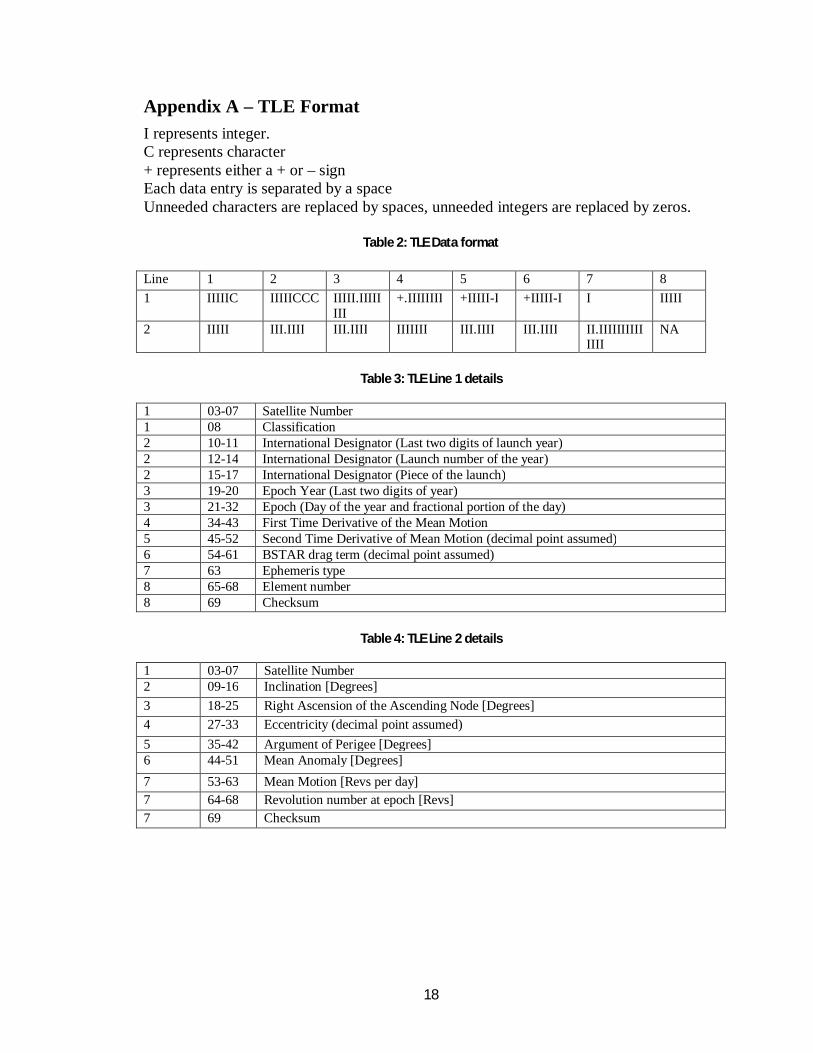
Appendix A – TLE Format
I represents integer. C represents character + represents either a + or – sign Each data entry is separated by a space Unneeded characters are replaced by spaces, unneeded integers are replaced by zeros.
Table 2: TLE Data format
Table 3: TLE Line 1 details
1 03-07 Satellite Number 1 08 Classification 2 10-11 International Designator (Last two digits of launch year) 2 12-14 International Designator (Launch number of the year) 2 15-17 International Designator (Piece of the launch) 3 19-20 Epoch Year (Last two digits of year) 3 21-32 Epoch (Day of the year and fractional portion of the day) 4 34-43 First Time Derivative of the Mean Motion 5 45-52 Second Time Derivative of Mean Motion (decimal point assumed) 6 54-61 BSTAR drag term (decimal point assumed) 7 63 Ephemeris type 8 65-68 Element number 8 69 Checksum
Table 4: TLE Line 2 details
1 03-07 Satellite Number 2 09-16 Inclination [Degrees]
3 18-25 Right Ascension of the Ascending Node [Degrees]
4 27-33 Eccentricity (decimal point assumed)
5 35-42 Argument of Perigee [Degrees] 6 44-51 Mean Anomaly [Degrees]
7 53-63 Mean Motion [Revs per day]
7 64-68 Revolution number at epoch [Revs]
7 69 Checksum
Line 1 2 3 4 5 6 7 8
1 IIIIIC IIIIICCC IIIII.IIIIIIII
+.IIIIIIII +IIIII-I +IIIII-I I IIIII
2 IIIII III.IIII III.IIII IIIIIII III.IIII III.IIII II.IIIIIIIIIIIIII
NA
19
Appendix B – Output Format
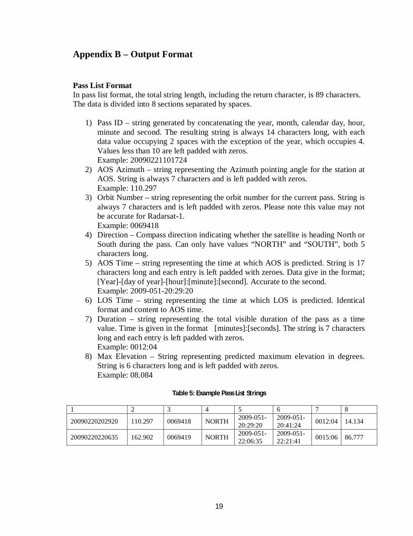
Pass List Format In pass list format, the total string length, including the return character, is 89 characters. The data is divided into 8 sections separated by spaces.
1) Pass ID – string generated by concatenating the year, month, calendar day, hour, minute and second. The resulting string is always 14 characters long, with each data value occupying 2 spaces with the exception of the year, which occupies 4. Values less than 10 are left padded with zeros. Example: 20090221101724
2) AOS Azimuth – string representing the Azimuth pointing angle for the station at AOS. String is always 7 characters and is left padded with zeros.
Example: 110.297 3) Orbit Number – string representing the orbit number for the current pass. String is
always 7 characters and is left padded with zeros. Please note this value may not be accurate for Radarsat-1. Example: 0069418
4) Direction – Compass direction indicating whether the satellite is heading North or South during the pass. Can only have values “NORTH” and “SOUTH”, both 5 characters long.
5) AOS Time – string representing the time at which AOS is predicted. String is 17 characters long and each entry is left padded with zeroes. Data give in the format; [Year]-[day of year]-[hour]:[minute]:[second]. Accurate to the second. Example: 2009-051-20:29:20
6) LOS Time – string representing the time at which LOS is predicted. Identical format and content to AOS time.
7) Duration – string representing the total visible duration of the pass as a time value. Time is given in the format [minutes]:[seconds]. The string is 7 characters long and each entry is left padded with zeros. Example: 0012:04
8) Max Elevation – String representing predicted maximum elevation in degrees. String is 6 characters long and is left padded with zeros. Example: 08.084
Table 5: Example Pass List Strings
1 2 3 4 5 6 7 8
20090220202920 110.297 0069418 NORTH 2009-051-20:29:20
2009-051-20:41:24
0012:04 14.134
20090220220635 162.902 0069419 NORTH 2009-051-22:06:35
2009-051-22:21:41
0015:06 86.777

20
Full Data/ Visible Data Format In Full Data or Visible Data format, the total string length, including the return character, is 173 characters. The data is divided into 15 sections separated by spaces. However, the first section contains a space. This was done to maintain compatibility with existing software.
1) Timestamp – This is a string representation of the time at which the data point is predicted. The format is as follows: [year]-[day of year]_ [hour]:[minute]:[second].[millisecond]. The underscore in the previous represents a space. The string is 22 characters long and each entry is left padded with zeros. Example: 2009-057 20:53:16.000
2) X position – String representing the x position of the satellite in kilometers in ECI TEME reference frame. String occupies 11 characters and is left padded with spaces. Example: 3017.854
3) Y position – Identical in formatting to the X position. 4) Z position – Identical in formatting to the X position. 5) X velocity – String representing current X velocity of the satellite in
kilometers/second in ECI TEME reference frame. String occupies 11 characters and is left padded with spaces. Example: -0.473
6) Y velocity – Identical in formatting to the X velocity. 7) Z velocity – Identical in formatting to the X velocity. 8) Azimuth angle – String representing azimuth angle in degrees from the station
coordinates to the satellite. String occupies 11 characters and is left padded with spaces. Example: 124.172
9) Elevation angle – String representing elevation angle in degrees from the station coordinates to the satellite. String occupies 11 characters and is left padded with spaces. Example: 0.030
10) Range – String representing range in kilometers from the antenna to the satellite. String occupies 14 characters, has 6 decimal places, and is left padded with spaces. Example: 3260.011543
11) Range Rate – String representing rate of change of Range in kilometers/second. String occupies 14 characters, has 6 decimal places, and is left padded with spaces. Example: -5.703276
12) Visible value – String representing whether or not the satellite is visible from the station. 1 is output if visible, 0 otherwise. String occupies 2 characters and is left padded with a space. If propagator is used in visible only mode, value will always be 1.
13) Latitude – String representing the current latitude of the satellite, if projected onto a flat earth map, in degrees. String occupies 11 characters and is left padded with spaces. Example: 28.057
14) Longitude - String representing the current longitude of the satellite, format identical to latitude.
15) Altitude – String representing the current altitude in kilometers above the reference geoid.
21
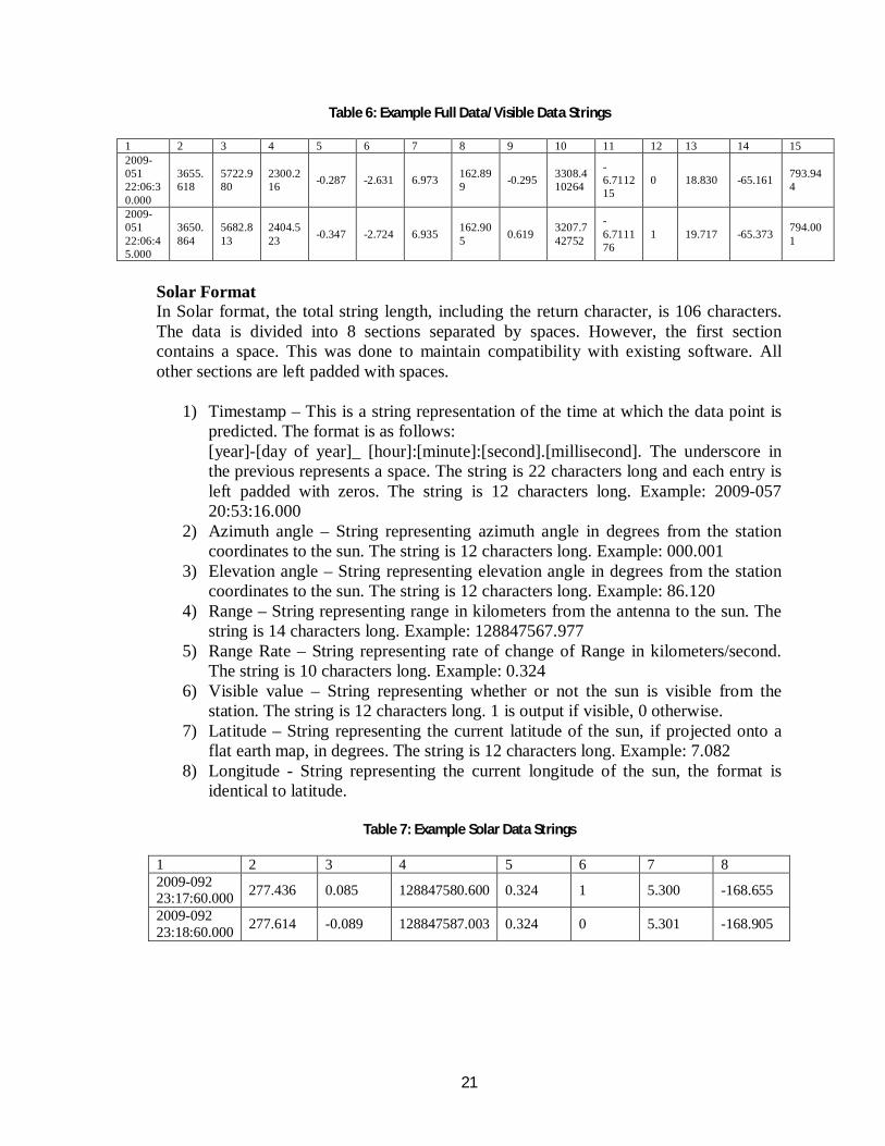
Table 6: Example Full Data/Visible Data Strings
1 2 3 4 5 6 7 8 9 10 11 12 13 14 15 2009-051 22:06:30.000
3655.618
5722.980
2300.216
-0.287 -2.631 6.973 162.899
-0.295 3308.410264
-6.711215
0 18.830 -65.161 793.944
2009-051 22:06:45.000
3650.864
5682.813
2404.523
-0.347 -2.724 6.935 162.905
0.619 3207.742752
-6.711176
1 19.717 -65.373 794.001
Solar Format In Solar format, the total string length, including the return character, is 106 characters. The data is divided into 8 sections separated by spaces. However, the first section contains a space. This was done to maintain compatibility with existing software. All other sections are left padded with spaces.
1) Timestamp – This is a string representation of the time at which the data point is predicted. The format is as follows: [year]-[day of year]_ [hour]:[minute]:[second].[millisecond]. The underscore in the previous represents a space. The string is 22 characters long and each entry is left padded with zeros. The string is 12 characters long. Example: 2009-057 20:53:16.000
2) Azimuth angle – String representing azimuth angle in degrees from the station coordinates to the sun. The string is 12 characters long. Example: 000.001
3) Elevation angle – String representing elevation angle in degrees from the station coordinates to the sun. The string is 12 characters long. Example: 86.120
4) Range – String representing range in kilometers from the antenna to the sun. The string is 14 characters long. Example: 128847567.977
5) Range Rate – String representing rate of change of Range in kilometers/second. The string is 10 characters long. Example: 0.324
6) Visible value – String representing whether or not the sun is visible from the station. The string is 12 characters long. 1 is output if visible, 0 otherwise.
7) Latitude – String representing the current latitude of the sun, if projected onto a flat earth map, in degrees. The string is 12 characters long. Example: 7.082
8) Longitude - String representing the current longitude of the sun, the format is identical to latitude.
Table 7: Example Solar Data Strings
1 2 3 4 5 6 7 8 2009-092 23:17:60.000
277.436 0.085 128847580.600 0.324 1 5.300 -168.655
2009-092 23:18:60.000
277.614 -0.089 128847587.003 0.324 0 5.301 -168.905

22
Appendix C – Data Comparison Graphs
Figure 12: Close up of Y-axis residual on Orbit 69419
Figure 13: X-axis coordinates over 4 days
23
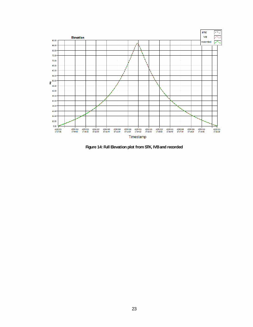
Figure 14: Full Elevation plot from STK, IVB and recorded