SG 5: FIT1001 Computer Systems S1 2006 1 Important Notice for Lecturers This file is provided as an...
55
SG 5: FIT1001 Computer Systems S1 2006 1 Important Notice for Lecturers • This file is provided as an example only • Lecturers are expected to modify / enhance slides to suit their teaching style • Lecturers are expected to cover the topics presented in these slides • Lecturers can export slides to another format if it suits their teaching style (but must cover the topics indicated in the slides) • This file should not be used AS PROVIDED – you should modify it to suit your own needs! • This slide should be deleted from this presentation • Provided by the FIT1001 SIG
-
Upload
roxanne-norman -
Category
Documents
-
view
214 -
download
1
Transcript of SG 5: FIT1001 Computer Systems S1 2006 1 Important Notice for Lecturers This file is provided as an...

SG 5: FIT1001 Computer Systems S1 2006 1
Important Notice for Lecturers
• This file is provided as an example only• Lecturers are expected to modify / enhance slides to
suit their teaching style • Lecturers are expected to cover the topics presented
in these slides• Lecturers can export slides to another format if it
suits their teaching style (but must cover the topics indicated in the slides)
• This file should not be used AS PROVIDED – you should modify it to suit your own needs!
• This slide should be deleted from this presentation• Provided by the FIT1001 SIG

www.monash.edu.au

www.monash.edu.au
FIT1001- Computer Systems
Lecture 5
Introduction to Instruction Set Architectures

SG 5: FIT1001 Computer Systems S1 2006 4
Lecture 5: Learning Objectives• Define instruction types and formats• Identify instruction operands and the addressing modes used• Write machine and assembler programs for a simple computer simulator• Explain the use of basic instruction types such as arithmetic, logic, branch
and subroutine call• Identify the features of several machine instruction sets
SG 5: FIT1001 Computer Systems S1 2006 5
Introduction
• Build upon the ideas and concepts introduced last week
• Machines instructions– Opcodes and operands
• High level languages– Hides the detail of the architecture from the programmer– Easier to program
• Why have knowledge of computer architectures and assembly?
– To write more efficient and effective programs

www.monash.edu.au
Instruction Formats

SG 5: FIT1001 Computer Systems S1 2006 7
Instruction Formats
• Instruction sets are differentiated by the following:– Number of bits per instruction (16, 32 and 64 are common)– Number of explicit operands per instruction (0, 1, 2, 3 – 3 is
most common)– Types of instructions and data each instruction can process– Operand storage in the CPU (stack or register based)– Operand location
> Register to register, register to memory, memory to memory
– Operations> Includes types of operations and which instruction can access
memory
– Type and size of operands (addresses, numbers, characters)

SG 5: FIT1001 Computer Systems S1 2006 8
Instruction Formats – Design Decisions
• The instruction set format is critical to the machines architecture
• Instruction set architectures are measured by several factors
– Main memory space occupied by a program– Instruction complexity (decoding, executing, complexity of
tasks required)– Instruction length (in bits)– Total number of instructions

SG 5: FIT1001 Computer Systems S1 2006 9
Instruction Formats – Design Decisions
• In designing an instruction set consideration is given to:
– Instruction length> Whether short, long, fixed or variable
– Number of operands– Number of addressable registers– Memory organization
> Whether byte- or word addressable
– Addressing modes> Choose any or all: direct, indirect or indexed
SG 5: FIT1001 Computer Systems S1 2006 10
Instruction Formats – Byte Ordering
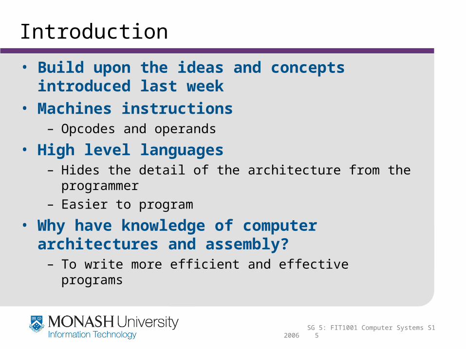
• Little verses Big Endian (recap)– Byte ordering is another major architectural consideration– If we have a two-byte integer, the integer may be stored so
that the least significant byte is followed by the most significant byte or vice versa
– In little endian machines> The least significant byte is followed by the most significant byte
– Big endian machines> Store the most significant byte first (at the lower address)
• Eg., The hexadecimal number 12345678

SG 5: FIT1001 Computer Systems S1 2006 11
Instruction Formats – Byte Ordering
• Big Endian– Advantages
> Is more natural
> The sign of the number can be determined by looking at the byte at address offset 0
> Strings and integers are stored in the same order
> Most bitmapped graphics are mapped with the most significant bit on the left
– Disadvantages> Must perform an addition when converting from a 32-bit integer
address to a 16-bit one
> Does not allow words to be written on non-word address boundaries (wastes space)
SG 5: FIT1001 Computer Systems S1 2006 12
Instruction Formats
• Little Endian– Advantages
> Makes it easier to place values on non-word boundaries
> High precision arithmetic is faster and easier
> Conversion from a 16-bit integer address to a 32-bit integer address does not require any arithmetic
– Disadvantages> Must reverse the byte order when working with large graphical
objects
SG 5: FIT1001 Computer Systems S1 2006 13
Instruction Formats – Byte Ordering
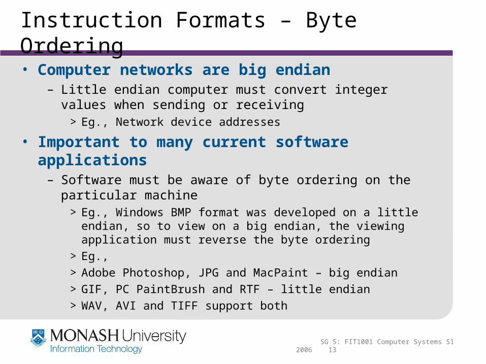
• Computer networks are big endian– Little endian computer must convert integer values when
sending or receiving > Eg., Network device addresses
• Important to many current software applications– Software must be aware of byte ordering on the particular
machine> Eg., Windows BMP format was developed on a little endian, so
to view on a big endian, the viewing application must reverse the byte ordering
> Eg.,
> Adobe Photoshop, JPG and MacPaint – big endian
> GIF, PC PaintBrush and RTF – little endian
> WAV, AVI and TIFF support both
SG 5: FIT1001 Computer Systems S1 2006 14
Instruction Formats – Stacks vs Registers
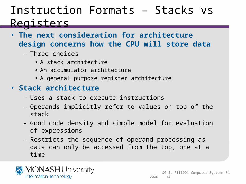
• The next consideration for architecture design concerns how the CPU will store data
– Three choices> A stack architecture
> An accumulator architecture
> A general purpose register architecture
• Stack architecture– Uses a stack to execute instructions– Operands implicitly refer to values on top of the stack– Good code density and simple model for evaluation of
expressions– Restricts the sequence of operand processing as data can
only be accessed from the top, one at a time

SG 5: FIT1001 Computer Systems S1 2006 15
Instruction Formats – Stacks vs Registers
– Hardware limitations on the amount and type of storage within the CPU means that the stack is actually located in memory
• Accumulator architecture – One operand of a binary operation is implicitly in the
accumulator– Minimize the internal complexity of the machine– Allows for very short instructions– Eg., MARIE– Memory traffic is very high

SG 5: FIT1001 Computer Systems S1 2006 16
Instruction Formats – Stacks vs Registers
• General purpose register (GPR) architecture– Uses sets of general purpose registers– Register sets are faster than memory – Easy for complier to deal with– Due to low costs large numbers of these registers are being
added– Results in longer instructions (but longer fetch and decode
times) – GPR architecture can be broken in three classifications
> Memory–memory: may have two or three operands in memory, an instruction may perform an operation without requiring any operand to be in a register
> Register-memory: at least one operand must be in a register and one in memory

SG 5: FIT1001 Computer Systems S1 2006 17
Instruction Formats – Stacks vs Registers
> Load-store: requires data to be moved into registers before any operations are performed

SG 5: FIT1001 Computer Systems S1 2006 18
Instruction Formats – Operands / Length
• The number of operands, addresses contained in each instruction has a direct impact on the length of the instruction itself
– Instructions can be formatted in two ways:> Fixed length: wastes space but is fast (when instruction
pipelining is used – discussed later)– Eg., MARIE used 16-bits, 4 for opcode and 12-bit operand
> Variable length: more complex to decode but save storage space
– Most common instruction formats include 0, 1, 2 or 3 operands
> Some instructions for MARIE have no operands where others have only one

SG 5: FIT1001 Computer Systems S1 2006 19
Instruction Formats – Operands / Length > Arithmetic and logic operation typically have two operands but
executed with one (if the accumulator is implicit)
– Can also extend to three operands if we consider the final destination as a third operand
– Can also use a tack that allows 0 operand instructions– Common instruction formats
> OPCODE only (0 addresses)> OPCODE + 1 address (usually memory)> OPCODE + 2 addresses (registers, or one register and one
memory)> OPCODE + 3 addresses (registers, or combinations of registers
and memory)
– All architectures have a limit of the number of operands allowed per instruction
> Eg., MARIE has a maximum of 1
SG 5: FIT1001 Computer Systems S1 2006 20
Instruction Formats – Operands / Length
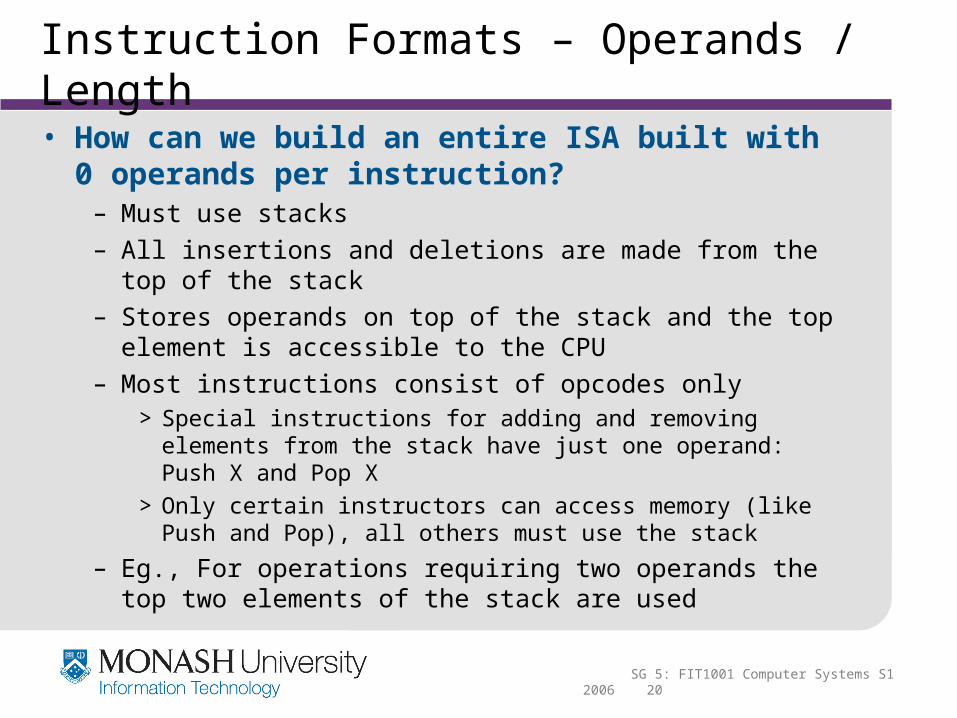
• How can we build an entire ISA built with 0 operands per instruction?
– Must use stacks– All insertions and deletions are made from the top of the
stack– Stores operands on top of the stack and the top element is
accessible to the CPU– Most instructions consist of opcodes only
> Special instructions for adding and removing elements from the stack have just one operand: Push X and Pop X
> Only certain instructors can access memory (like Push and Pop), all others must use the stack
– Eg., For operations requiring two operands the top two elements of the stack are used

SG 5: FIT1001 Computer Systems S1 2006 21
Instruction Formats – Operands / Length
> Add: CPU adds the two top elements of the stack by popping them both, adding them, and pushing the sum onto the top of the stack
> Subtract: top stack element is subtracted from the next to top element by popping both, subtracting them, and pushing the sum onto the top of the stack
• Stack architectures require us to think about arithmetic expressions a little differently
– We are accustomed to writing expressions using infix notation, such as: Z = X + Y
– Stack arithmetic requires that we use postfix notation: Z = XY+
> Postfix is also know as reverse Polish notation
> Prefix notation places the operator first so Z = + XY

SG 5: FIT1001 Computer Systems S1 2006 22
Instruction Formats – Operands / Length
– The principal advantage of postfix notation is that parentheses are not used
> Eg., Take the infix expression Z = (X * Y) + (W * U)– Becomes: Z = X Y * W U * + in postfix notation
– In a stack ISA the postfix expression Z = X Y * W U * +might look like:
PUSH X
PUSH Y
MULT
PUSH W
PUSH U
MULT
ADD
PUSH Z
Assumes that MULT and ADD instructions use the two operands on the stack top, pop them and push the result of the operation
The result of a binary operation is implicitly stored on the top of the stack.
SG 5: FIT1001 Computer Systems S1 2006 23
Instruction Formats – Operands / Length
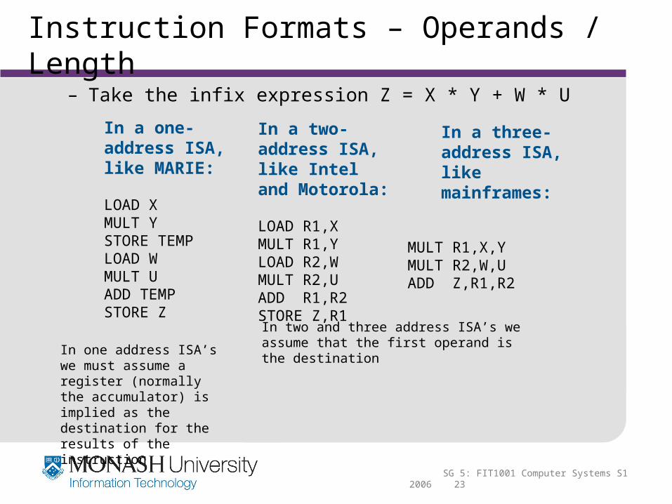
– Take the infix expression Z = X * Y + W * U
In a one-address ISA, like MARIE:
LOAD XMULT YSTORE TEMPLOAD WMULT UADD TEMPSTORE Z
In a two-address ISA, like Intel and Motorola:
LOAD R1,XMULT R1,YLOAD R2,WMULT R2,UADD R1,R2STORE Z,R1
In a three-address ISA, like mainframes:
MULT R1,X,YMULT R2,W,UADD Z,R1,R2
In two and three address ISA’s we assume that the first operand is the destinationIn one address ISA’s we
must assume a register (normally the accumulator) is implied as the destination for the results of the instruction

SG 5: FIT1001 Computer Systems S1 2006 24
Instruction Formats – Expanding Opcodes
• So far:– We have seen how instruction length is affected by the
number of operands supported by the ISA– In any instruction set, not all instructions require the same
number of operands– Operations that require no operands, such as HALT,
necessarily waste some space when fixed-length instructions are used
• One way to recover some of this space is to use expanding opcodes
– Make some opcodes short, but provide a means where longer ones are needed
– Could have 2 or 3 operands, or even multiple opcodes

SG 5: FIT1001 Computer Systems S1 2006 25
Instruction Formats – Expanding Opcodes
• Eg., A system 16-bit instructions, 16 registers (MARIE only has an accumulator) and 4K of memory
– We need 4-bits to access one of the registers– We also need 12-bits for a memory address– If the system is to have 16-bit instructions, we have two
choices for our instructions:Implies data must be loaded into registers first
As in MARIE, a 12-bit memory address

SG 5: FIT1001 Computer Systems S1 2006 26
Instruction Formats – Expanding Opcodes
• If we allow the length of the opcode to vary we could create a very rich instruction set:
– Expanding opcodes make the decoding more complex
15instructions
14instructions
31instructions
16instructions

SG 5: FIT1001 Computer Systems S1 2006 27
Instruction Formats – Expanding Opcodes
– Each instruction cannot be decoded by simply looking at a bit pattern and deciding which instruction it is
– Some type of algorithm must be used:if (leftmost four bits != 1111)
{Execute appropriate 3-address instruction}
else
if (leftmost seven bits != 1111 111)
{Execute appropriate 2-address instruction}
else
if (leftmost twelve bits != 1111 111 1111)
{Execute appropriate 1-address instruction}
else
{Execute appropriate 0-address instruction}
– At each stage one code is used to indicate that more bits should be looked at
> Trading opcode space for operand space

www.monash.edu.au
Instruction Types

SG 5: FIT1001 Computer Systems S1 2006 29
Instruction Types
• Instructions fall into several broad categories that you should be familiar with:
– Data movement> Transfers data between memory and registers, registers to
registers and registers to memory> Can have different instructions depending on the source and
destination> Eg., MOVER (requires 2 register operands)
Eg., MOVE (requires 1 memory and 1 register operand)> Eg., LOAD and STORE
– Arithmetic> Operations on integer and floating point numbers> Many sets provide different arithmetic instructions for various
data sizes> Different instructions can exist for various memory / register
access

SG 5: FIT1001 Computer Systems S1 2006 30
Instruction Types
– Boolean> Performs Boolean operations
> Includes AND, NOT, OR and XOR
– Bit manipulation> Used for settings and resetting individual bits (or groups of bits)
within a given data word
> Includes both arithmetic and logical shift / rotate instructions (both to the left and right)
– Logical shift: shifts bits to either the left or right by a specified amount (replacing with zeros)
– Arithmetic shift: shifts bits to either the left or right but sign bit is retained (replacing shifted bits with zeros)
– Rotate: shift instructions that shift in the bits that are shifted out

SG 5: FIT1001 Computer Systems S1 2006 31
Instruction Types
– I/O> Vary greatly from architecture to architecture
> Basic schemes are programmed, interrupt driven and DMA– Discussed in Study Guide 8
– Control transfer> Includes branches, skips and procedure calls
> Braches can be unconditional or conditional
> Skip instructions are basically branch instructions with implied addresses
> Procedure calls are special branch instructions that automatically save the return address
– Special purpose> Includes those used for string processing, high level language
support, protection, flag control can cache management

www.monash.edu.au
Addressing

SG 5: FIT1001 Computer Systems S1 2006 33
Addressing – Data Types
• Two important addressing issues– Types of data that can be addressed– Various addressing modes
• Data types– Hardware support is needed for a particular data type if the
instruction is to reference that type– Earlier in the unit we discussed data types, including number
and characters> Numeric: integers signed and unsigned in various lengths, short
(16-bit) or long (32-bit) / floating point with lengths of 32, 64 and 128 bits
> Non-numeric: strings such as instructions to copy, search or move, Booleans (AND, OR, NOR, NOT) and pointers (addresses in memory)

SG 5: FIT1001 Computer Systems S1 2006 34
Addressing – Addressing Modes
• Addressing modes– Addressing modes specify where an operand is located– They can specify a constant, a register, or a memory location– The actual location of an operand is its effective address– Certain addressing modes allow us to determine the address
of an operand dynamically
• Types of addressing modes – Immediate addressing
> The value is referenced immediately after the opcode
> Eg., LOAD 008 would load the numeric value 8 into the accumulator
> Very fast as the value is included with the instruction
> Not flexible

SG 5: FIT1001 Computer Systems S1 2006 35
Addressing – Addressing Modes
– Direct addressing > Where the address of the data is given in the instruction
> Eg., LOAD 008 would load the value located at memory address 008 into the accumulator
> Quite fast as value is quickly accessible
> More flexible than immediate addressing as the value in the memory location is variable
– Register addressing > The data is located in a register
> Similar to direct addressing but uses a register
– Indirect addressing> Provides the address of the address of the data in the instruction
(pointers)
> Very powerful and very flexible

SG 5: FIT1001 Computer Systems S1 2006 36
Addressing – Addressing Modes
– Register indirect addressing> Uses a register to store the address of the address of the data
> A variation on indirect addressing
– Indexed and based addressing > Indexed addressing uses a register (implicitly or explicitly) as an
offset, which is added to the address in the operand to determine the effective address of the data
– Eg., LOAD X, R1 is the index register with the value 1, the effective address would be X + 1
> Based addressing is similar to indexed addressing except that a base register is used instead of an index register
> The difference between these two is that an index register holds an offset relative to the address given in the instruction, a base register holds a base address where the address field represents a displacement from this base

SG 5: FIT1001 Computer Systems S1 2006 37
Addressing – Addressing Modes
– Stack addressing> The operand is assumed to be on the stack
– Additional addressing modes> Many variations on the above schemes exist
– Indirect indexed– Base/offset– Self-relative– Auto increment - decrement
• Summary of basic addressing modes

SG 5: FIT1001 Computer Systems S1 2006 38
Addressing – Addressing Modes
• Eg., LOAD 800 with memory and register R1 as:
– What value is loaded into the accumulator for each addressing mode?

www.monash.edu.au
Instruction Level Pipelining

SG 5: FIT1001 Computer Systems S1 2006 40
Instruction Level Pipelining
• Should be reasonably familiar with the fetch-decode-execute cycle
– Each pulse of the computer’s clock is used to control on step in a sequence
• Instruction level processing– Some CPUs divide the fetch-decode-execute cycle into
smaller steps– These smaller steps can often be executed in parallel to
increase throughput– Such parallel execution is called instruction-level pipelining
(sometimes abbreviated ILP in the literature)
SG 5: FIT1001 Computer Systems S1 2006 41
Instruction Level Pipelining
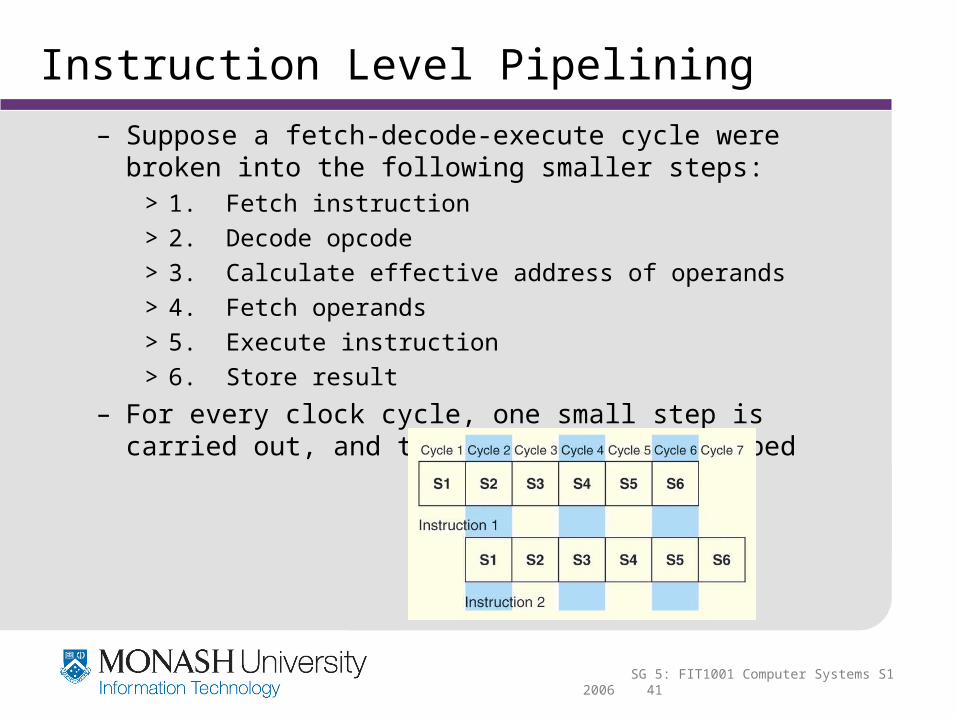
– Suppose a fetch-decode-execute cycle were broken into the following smaller steps:
> 1. Fetch instruction
> 2. Decode opcode
> 3. Calculate effective address of operands
> 4. Fetch operands
> 5. Execute instruction
> 6. Store result
– For every clock cycle, one small step is carried out, and the stages are overlapped

SG 5: FIT1001 Computer Systems S1 2006 42
Instruction Level Pipelining
– The goal is to balance the time taken by each pipeline stage> Otherwise faster stages will be waiting for slower ones
• Theoretical speed– Let tp be the time per stage
– Each instruction represents a task (T) in the pipeline
– The first task (instruction) requires k * tp time to complete in a k-stage pipeline
– The remaining (n - 1) tasks emerge from the pipeline one per cycle
– The total time to complete the remaining tasks is (n - 1) tp
– Thus, to complete n tasks using a k-stage pipeline requires:
(k * tp) + (n - 1) tp = (k + n - 1) tp

SG 5: FIT1001 Computer Systems S1 2006 43
Instruction Level Pipelining
– Speedup gained by using a pipeline
> Without a pipeline the time requires is ntn cycles, where tn = k * tp
– If we take the limit as n approaches infinity, (k + n - 1) approaches n, which results in a theoretical speedup of:
> The theoretical speedup (k) is the number of stages in a pipeline

SG 5: FIT1001 Computer Systems S1 2006 44
Instruction Level Pipelining
– Our equations take a number of things for granted> First, we have to assume that the architecture supports fetching
instructions and data in parallel
> Second, we assume that the pipeline can be kept filled at all times
– This is not always the case as pipeline hazards arise that cause pipeline conflicts and stalls
– It may appear that more stages equals faster performance> This is true to a point
> Fixed overheads exist involving the movement of data from memory to registers
> The amount of control logic also increases in size proportional to the number of stages
> Also several conditions, “pipeline conflicts” affects the execution of instructions
SG 5: FIT1001 Computer Systems S1 2006 45
Instruction Level Pipelining
• Pipeline conflicts– Resource conflicts
> Eg., If one instruction is storing a value to memory while another is being fetched from memory, both instructions need to access memory
> Resolved by:– Allowing first instruction to continue while forcing the instruction
fetch to wait– Providing two separate pathways
– Data dependencies> Arises when the result of one instruction, not yet available, is to
be used as an operand to a following instruction
> Several resolutions:– Special hardware added to detect and insert a brief delay / route
data through different paths between pipeline stages

SG 5: FIT1001 Computer Systems S1 2006 46
Instruction Level Pipelining– Some compliers allow the reorder of instructions which delays the
loading of any conflicting data» The program logic or output is not affected
– Conditional branch statements> Branching instructions allow the flow of the program to be
altered
> Branching causes major problems in terms of pipelining– Several instructions can be fetched and decoded before a
preceding branch instruction is executed
> Options:– Branch prediction – using logic to make the best guess– Delayed branch – compliers rearrange machine code to include a
delay

www.monash.edu.au
Examples of Computer Architecture

SG 5: FIT1001 Computer Systems S1 2006 48
Examples of Computer Architecture
• Intel architecture– Architecture basics
> Little endian
> Two address architecture
> Variable length instructions / operations (1,2 or 4 bytes)
> Register-memory architecture
– Pipelining> Intel introduced pipelining with the Pentium chip
> The first Pentium had two five-stage pipelines
> Each subsequent Pentium processor had a longer pipeline than its predecessor
– Pentium II has 12 (added to address MMX technology)– Pentium III has 14– Pentium IV has 24– The Itanium (IA-64) has only a 10-stage pipeline

SG 5: FIT1001 Computer Systems S1 2006 49
Examples of Computer Architecture
– Addressing modes> Intel processors support a wide array of addressing modes
> The original Intel 8086 provided 17 ways to address memory– Most of them are variants on the methods presented
> The Pentium architecture support the same addressing modes as their predecessors (for backward compatibility)
– Also introduces new modes
> The Itanium IA-64 supports only one: register indirect addressing (with optional post increment)
– Limiting but follows RISC philosophy (as IA-64 is RISC based)– Reduces the need for specialised hardware to support different
addressing modes

SG 5: FIT1001 Computer Systems S1 2006 50
Examples of Computer Architecture
• MIPS architecture– MIPS Technologies Inc– Used in:
> Computers (such as Silicon Graphics) / Embedded systems / Computerised toys (Nintendo / Sony) / Routers (Cisco)
– Architecture basics> Little endian
> Word addressable
> Three address architecture
> Fixed length instructions
> Load and store architecture – Only load and store instructions can access memory– All other instructions must use registers for operands
SG 5: FIT1001 Computer Systems S1 2006 51
Examples of Computer Architecture
– Pipelining– Like Intel the pipeline size of the MIPS processors has grown
> The R2000 and R3000 have five-stage pipelines
> The later R4000 and R4400 have 8-stage pipelines
> The R10000 has three pipelines depending on the functional unit through which the instruction passes
– A five-stage pipeline for integer instructions– A seven-stage pipeline for floating-point instructions– A six-state pipeline for LOAD/STORE instructions
– Addressing> The ISA uses only base addressing mode
> The assembler accommodates programmers who need to use immediate, register, direct, indirect register, base, or indexed addressing modes

SG 5: FIT1001 Computer Systems S1 2006 52
Examples of Computer Architecture
• Java Virtual machine– The Java programming language is an interpreted language
> Runs in a software machine called the Java Virtual Machine (JVM)
> A JVM is written the native language (ISA) for a particular processor, including MIPS and Intel
– JVM has an ISA all of its own - called bytecode> This ISA was designed to be compatible with the architecture of
any machine on which the JVM is running
> Once available on a given architecture the JVM can run any Java program complied on another architecture
> Bytecodes are interpreted by the JVM one bytecode at a time – Each bytecode causes a jump to a specific block of code which
implements the bytecode

SG 5: FIT1001 Computer Systems S1 2006 53
Examples of Computer Architecture

SG 5: FIT1001 Computer Systems S1 2006 54
Examples of Computer Architecture
– Architecture> Java bytecode is a stack-based language
> Most instructions are zero address instructions
> The JVM has four registers that provide access to five regions of main memory
– All references to memory are offsets from these registers– Pointers or absolute memory references are not used
> Uses 2’s complement for signed integers (does not allow unsigned integers)
> Characters are encoded using 16-bit Unicode
> Lack of general registers is detrimental to performance as memory references increase
– Java was designed for platform interoperability, not performance!

SG 5: FIT1001 Computer Systems S1 2006 55
Next Week
• Study Guide 6– Computer Program Execution Concepts