SFP28 DWDM Transceiver
10
SFP28 DWDM Transceiver FCS8DxxB53xDL10
Transcript of SFP28 DWDM Transceiver

SFP28 DWDM TransceiverFCS8DxxB53xDL10
Part Number Operating Case temperature DDMI
Transceiver
Yes
Product Selection
Product Features Applications
SFP28 DWDM Transceiver
FCS8DxxB53xDL10
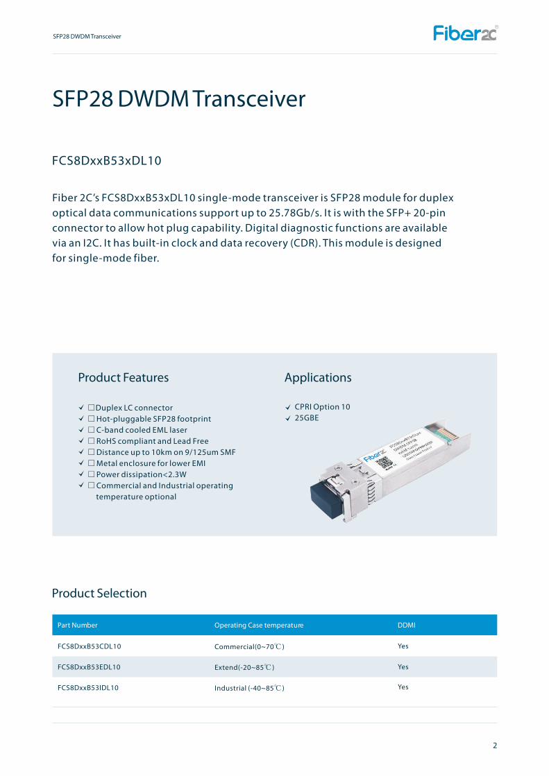
Fiber 2C’s FCS8DxxB53xDL10 single-mode transceiver is SFP28 module for duplex optical data communications support up to 25.78Gb/s. It is with the SFP+ 20-pin connector to allow hot plug capability. Digital diagnostic functions are available via an I2C. It has built-in clock and data recovery (CDR). This module is designed for single-mode fiber.
Duplex LC connectorHot-pluggable SFP28 footprint C-band cooled EML laserRoHS compliant and Lead Free Distance up to 10km on 9/125um SMFMetal enclosure for lower EMI Power dissipation<2.3WCommercial and Industrial operating temperature optional
CPRI Option 1025GBE
FCS8DxxB53CDL10
FCS8DxxB53EDL10
FCS8DxxB53IDL10
Commercial(0~70℃ )
Extend(-20~85℃ )
Industrial (-40~85℃ )
Yes
Yes
2
SFP28 DWDM Transceiver

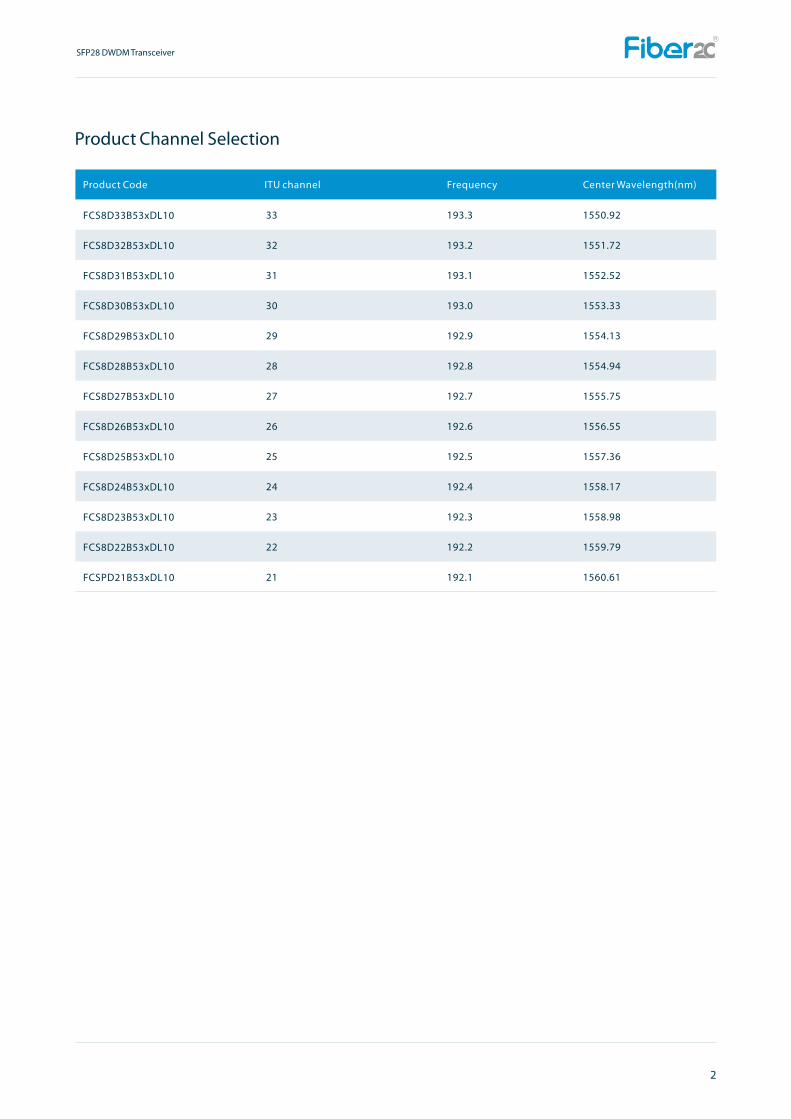
Product Channel Selection
Product Code ITU channel Frequency Center Wavelength(nm)
FCS8D60B53xDL10
FCS8D59B53xDL10
FCS8D58B53xDL10
FCS8D57B53xDL10
FCS8D56B53xDL10
FCS8D55B53xDL10
FCS8D54B53xDL10
FCS8D53B53xDL10
FCS8D52B53xDL10
FCS8D51B53xDL10
FCS8D50B53xDL10
FCS8D49B53xDL10
FCS8D48B53xDL10
FCS8D47B53xDL10
FCS8D46B53xDL10
FCS8D45B53xDL10
FCS8D44B53xDL10
FCS8D43B53xDL10
FCS8D42B53xDL10
FCS8D41B53xDL10
FCS8D40B53xDL10
FCS8D39B53xDL10
FCS8D38B53xDL10
FCS8D37B53xDL10
FCS8D36B53xDL10
FCS8D35B53xDL10
FCS8D34B53xDL10
60
59
58
57
56
55
54
53
52
51
50
49
48
47
46
45
44
43
42
41
40
39
38
37
36
35
34
196.0
195.9
195.8
195.7
195.6
195.5
195.4
195.3
195.2
195.1
195.0
194.9
194.8
194.7
194.6
194.5
194.4
194.3
194.2
194.1
194.0
193.9
193.8
193.7
193.6
193.5
193.4
1529.55
1530.33
1531.12
1531.90
1532.68
1533.47
1534.25
1535.04
1535.82
1536.61
1537.40
1538.19
1538.98
1539.77
1540.56
1541.35
1542.14
1542.94
1543.73
1544.53
1545.32
1546.12
1546.92
1547.72
1548.51
1549.32
1550.12
2
SFP28 DWDM Transceiver
Product Channel Selection
Product Code ITU channel Frequency Center Wavelength(nm)
2
SFP28 DWDM Transceiver
FCS8D33B53xDL10
FCS8D32B53xDL10
FCS8D31B53xDL10
FCS8D30B53xDL10
FCS8D29B53xDL10
FCS8D28B53xDL10
FCS8D27B53xDL10
FCS8D26B53xDL10
FCS8D25B53xDL10
FCS8D24B53xDL10
FCS8D23B53xDL10
FCS8D22B53xDL10
FCSPD21B53xDL10
33
32
31
30
29
28
27
26
25
24
23
22
21
193.3
193.2
193.1
193.0
192.9
192.8
192.7
192.6
192.5
192.4
192.3
192.2
192.1
1550.92
1551.72
1552.52
1553.33
1554.13
1554.94
1555.75
1556.55
1557.36
1558.17
1558.98
1559.79
1560.61

2
SFP28 DWDM Transceiver
Regulatory Compliance
Pin Descriptions
ESD to the Electrical PINs: compatible with MIL-STD-883 Method 3015
ESD to the Duplex LC Receptacle: compatible with IEC 61000-4-2
Immunity compatible with IEC 61000-4-3
EMI compatible with FCC Part 15 Class B EN55022 Class B (CISPR 22B) VCCI Class B
Laser Eye Safety compatible with FDA 21CFR 1040.10 and 1040.11 EN60950,
EN (IEC) 60825-1,2
RoHS compliant with RoHS 2 (2011/65/EU)
1
2
3
4
5
6
7
8
9
10
11
12
13
14
15
16
17
18
19
20
VeeT
TX Fault
TX Disable
SDA
SCL
Mod_ABS
RS0
LOS
RS1
VeeR
VeeR
RD-
RD+
VeeR
VccR
VccT
VeeT
TD+
TD-
VeeT
Transmitter Ground (Common with Receiver Ground)
Transmitter Fault. LVTTL-O
Transmitter Disable. Laser output disabled on high or open. LVTTL-I
2-Wire Serial Interface Data Line(Same as MOD-DEF2 in INF-8074i). LVTTL-I/O
2-Wire Serial Interface Data Line(Same as MOD-DEF2 in INF-8074i). LVTTL-I
Module Absent, Connect to VeeT or VeeR in Module.
Rate Select 0, optionally controls SFP+ module receiver LVTTL-I
Loss of Signal indication. Logic 0 indicates normal operation. LVTTL-O
Rate Select 1, optionally controls SFP+ module transmitter. LVTTL-I
Receiver Ground (Common with Transmitter Ground)
Receiver Ground (Common with Transmitter Ground)
Receiver Inverted DATA out. AC Coupled. CML-O
Receiver Non-inverted DATA out. AC Coupled. CML-O
Receiver Ground (Common with Transmitter Ground)
Receiver Power Supply
Transmitter Power Supply
Transmitter Ground (Common with Receiver Ground)
Transmitter Non-Inverted DATA in. AC Coupled. CML- I
Transmitter Inverted DATA in. AC Coupled. CML- I
Transmitter Ground (Common with Receiver Ground)
1
2
3
2
2
2
4
5
4
1
1
1
6
6
1
1
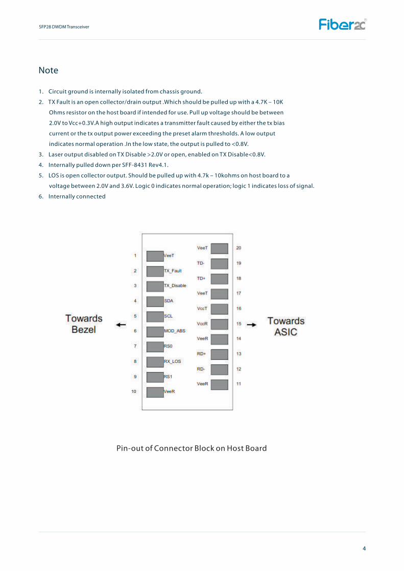
1. Circuit ground is internally isolated from chassis ground.
2. TX Fault is an open collector/drain output .Which should be pulled up with a 4.7K – 10K
Ohms resistor on the host board if intended for use. Pull up voltage should be between
2.0V to Vcc+0.3V.A high output indicates a transmitter fault caused by either the tx bias
current or the tx output power exceeding the preset alarm thresholds. A low output
indicates normal operation .In the low state, the output is pulled to <0.8V.
3. Laser output disabled on TX Disable >2.0V or open, enabled on TX Disable<0.8V.
4. Internally pulled down per SFF-8431 Rev4.1.
5. LOS is open collector output. Should be pulled up with 4.7k – 10kohms on host board to a
voltage between 2.0V and 3.6V. Logic 0 indicates normal operation; logic 1 indicates loss of signal.
6. Internally connected
Note
Pin-out of Connector Block on Host Board
4
SFP28 DWDM Transceiver

5
Recommend Circuit Schematic
SFP28 DWDM Transceiver
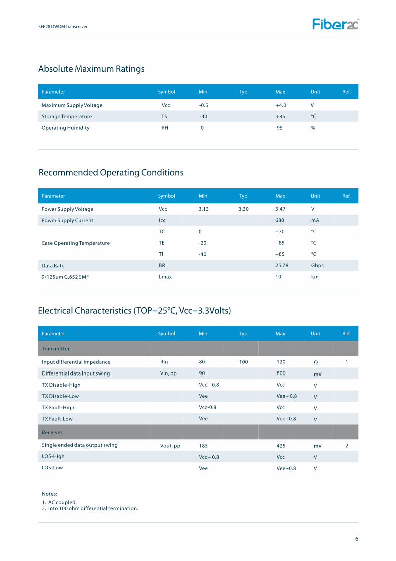
Maximum Supply Voltage Vcc -0.5 +4.0 V
Storage Temperature TS -40 +85 °C
Operating Humidity RH 0 95 %
Transmitter
Receiver
Notes:
Electrical Characteristics (TOP=25°C, Vcc=3.3Volts)
1. AC coupled.2. Into 100 ohm differential termination.
Rin
Vin, pp
1
2
Ω
mV
V
V
V
V
6
Absolute Maximum Ratings
Recommended Operating Conditions
Vout, pp
100
mV
V
V
Power Supply Voltage
Power Supply Current
Case Operating Temperature
Data Rate
9/125um G.652 SMF
Vcc
Icc
TC
TE
TI
BR
Lmax
3.13
0
-20
-40
3.47
680
+70
+85
+85
25.78
10
3.30 V
mA
°C
°C
°C
Gbps
km
Input differential impedance
Differential data input swing
TX Disable-High
TX Disable-Low
TX Fault-High
TX Fault-Low
Single ended data output swing
LOS-High
LOS-Low
80
90
Vcc – 0.8
Vee
Vcc-0.8
Vee
185
Vcc – 0.8
Vee
120
800
Vcc
Vee+ 0.8
Vcc
Vee+0.8
425
Vcc
Vee+0.8
SFP28 DWDM Transceiver

Transmitter
Optical Characteristics (TOP=25°C, Vcc=3.3 Volts)
7
Mechanical Specifications
Output Opt. Power
Optical Wavelength
Side-Mode Suppression Ratio
Spectral Width(-20dB)
Dispersion penalty@15km fiber (BER=10-12)
Optical Extinction Ratio
RX Sensitivity @25.78Gb/s
OMA RX Sensitivity @25.78Gb/s
Receiver Overload @25.78Gb/s
Optical Center Wavelength
LOS De-Assert
LOS Assert
LOS Hysteresis
Receiver
PO
λ
SMSR
Δλ
DP
ER
SENS
SENS1
Po
λC
LOSD
LOSA
0
As per ITU-T 694.1
35
4
-2
1520
-35
0.5
5
1
3.0
+
-13.5
-12
1600
-15
6
dBm
nm
dB
nm
dB
dB
dBm
dBm
dBm
nm
dBm
dBm
dB
1
1
Notes: 311.Measured with data rate at 25.78Gb/s, ER=7dB, Tc=25degC, BER less than 5E-5 with PRBS 2 -1.
Fiber 2C’s Small Form Factor Pluggable (SFP28) transceivers are compatible with the dimensions defined by the SFP Multi-Sourcing Agreement (MSA), dimensions are in mm.
FCS8DxxB53xDL10
SFP28 DWDM Transceiver

EEPROM Information
EEPROM memory map specific data field description is as below:
8
SFP28 DWDM Transceiver
Digital Diagnostic Monitoring Interface
Parameter Range Accuracy Calibration
Internal
Internal
Internal
Internal
Internal
Five transceiver parameter values are monitored. The following table defines the monitored parameter’s accuracy.
Temperature
Voltage
Bias Current
TX Power
RX Power
0 to +70°C(C)
2.97 to 3.63V
0 to 100mA
0 to +5dBm
-15 to -2dBm
±3°C
±3%
±10%
±3dB
±3dB
-20 to +85°C(D)
-40 to +85°C(I)