SFP+ SI Guideline - MolexSI… · · 2011-03-22SFP+ SI Guideline REVISION: ECR/ECN INFORMATION:...
18
SFP+ SI Guideline REVISION: ECR/ECN INFORMATION: SHEET No. EC No: UCP2007-9999 001 DATE: 2007 / 1 / 26 TITLE: SI Guideline / Fixture Definition For Stacked SFP+ 1 of 18 DOCUMENT NUMBER: CREATED / REVISED BY: CHECKED BY: APPROVED BY: TS-75640 Patrick Casher David Stevenson Rich Nelson TEMPLATE FILENAME: PRODUCT_SPEC[SIZE_A](V.1).DOC TABLE OF CONTENTS 1.0 – SCOPE ………………….…………………………………. 2 2.0 – PRODUCT DESCRIPTION ……………………………… 2 3.0 – APPLICABLE DOCUMENTS …………………………… 3 4.0 – APPLICATION DESCRIPTION …....……………………. 3 5.0 – CONNECTOR TIME DOMAIN DATA ………..…………. 4 6.0 – CONNECTOR FREQUENCY DOMAN DATA …………. 8 7.0 – SFP+ CHANNEL MODELS ………….….……………….. 10 8.0 – TEST FIXTURE DESCRIPTION ………….….…….……. 17
Transcript of SFP+ SI Guideline - MolexSI… · · 2011-03-22SFP+ SI Guideline REVISION: ECR/ECN INFORMATION:...

SFP+ SI Guideline
REVISION: ECR/ECN INFORMATION: SHEET No.
EC No: UCP2007-9999 001 DATE: 2007 / 1 / 26
TITLE: SI Guideline / Fixture Definition For Stacked SFP+
1 of 18
DOCUMENT NUMBER: CREATED / REVISED BY: CHECKED BY: APPROVED BY:
TS-75640 Patrick Casher David Stevenson Rich Nelson TEMPLATE FILENAME: PRODUCT_SPEC[SIZE_A](V.1).DOC
TABLE OF CONTENTS
1.0 – SCOPE ………………….…………………………………. 2 2.0 – PRODUCT DESCRIPTION ……………………………… 2 3.0 – APPLICABLE DOCUMENTS …………………………… 3 4.0 – APPLICATION DESCRIPTION …....……………………. 3 5.0 – CONNECTOR TIME DOMAIN DATA ………..…………. 4 6.0 – CONNECTOR FREQUENCY DOMAN DATA …………. 8 7.0 – SFP+ CHANNEL MODELS ………….….……………….. 10 8.0 – TEST FIXTURE DESCRIPTION ………….….…….……. 17

SFP+ SI Guideline
REVISION: ECR/ECN INFORMATION: SHEET No.
EC No: UCP2007-9999 001 DATE: 2007 / 1 / 26
TITLE: SI Guideline / Fixture Definition For Stacked SFP+
2 of 18
DOCUMENT NUMBER: CREATED / REVISED BY: CHECKED BY: APPROVED BY:
TS-75640 Patrick Casher David Stevenson Rich Nelson TEMPLATE FILENAME: PRODUCT_SPEC[SIZE_A](V.1).DOC
SIGNAL INTEGRITY REPORT
1.0 SCOPE
This Signal Integrity report covers the Stacked SFP and SFP+ performance for the 2X1, 2X2, 2X4, 2X5, and 2X6 Stacked SFP and SFP+ Multi-Port Connectors with Light Pipes. Disclaimer: Molex does not guarantee the performance of the final product to the information provided in this document. All information in this report is considered Molex proprietary and confidential. This guide is not intended as a substitute for engineering analysis
2.0 PRODUCT DESCRIPTION
2.1 EVALUATED: 75640 (2X1 STACKED SFP MULTI-PORT CONNECTOR WITH LIGHT PIPES)
Also valid for: Stacked SFP Multi-Port Connector with Light Pipes 75714 (2x2) 75450 (2x4) 75734 (2x5) 75451 (2x6)
Stacked SFP+ Multi-Port Connector with Elastomeric EMI Gasket and Light Pipes
76090 (2x1) 76091 (2x2) 76092 (2x4) 76093 (2x5) 76094 (2x6)
Stacked SFP+ Multi-Port Connector with Metal EMI Gasket and Light Pipes 76044 (2x1) 76045 (2x2) 76046 (2x4) 76047 (2x5) 76048 (2x6) 76200 (2x6 without Light Pipes)

SFP+ SI Guideline
REVISION: ECR/ECN INFORMATION: SHEET No.
EC No: UCP2007-9999 001 DATE: 2007 / 1 / 26
TITLE: SI Guideline / Fixture Definition For Stacked SFP+
3 of 18
DOCUMENT NUMBER: CREATED / REVISED BY: CHECKED BY: APPROVED BY:
TS-75640 Patrick Casher David Stevenson Rich Nelson TEMPLATE FILENAME: PRODUCT_SPEC[SIZE_A](V.1).DOC
3.0 APPLICABLE DOCUMENTS AND SPECIFICATIONS
Product Specification – PS-75310-001 Routing Recommendations – AS-76090-999 Electrical Model – EE-76090-001
SFF-8431 Specifications for Enhanced 8.5 and 10 Gigabit Small Form Factor Pluggable Module
"SFP+", SFF Committee, Revision 1.2, December 21, 2006.
4.0 APPLICATION DESCRIPTION
- Fibre Channel, Gigabit Ethernet, InfiniBand
- Networking
- Storage
- Telecommunications
- Hubs, Switches, Routers, Servers, Network Interface Cards (NICs)

SFP+ SI Guideline
REVISION: ECR/ECN INFORMATION: SHEET No.
EC No: UCP2007-9999 001 DATE: 2007 / 1 / 26
TITLE: SI Guideline / Fixture Definition For Stacked SFP+
4 of 18
DOCUMENT NUMBER: CREATED / REVISED BY: CHECKED BY: APPROVED BY:
TS-75640 Patrick Casher David Stevenson Rich Nelson TEMPLATE FILENAME: PRODUCT_SPEC[SIZE_A](V.1).DOC
5.0 CONNECTOR TIME DOMAIN DATA
5.1 TIME DOMAIN (TDR IMPEDANCE CHARACTERIZATION)
Equipment: Agilent Infiniium DCA-J 86100c01 Digital Communications Analyzer
5.1.1 TEST SUBJECT: UPPER PORT
Shortest Press-Fit Pin Via Stub (Bottom Feed, Driven Via, Best Case) Connector Terminals 12 & 13
Rise-time 100ps (20-80%) Rise-time 50ps (20-80%) Representative Data Rates 2.5 to 3.125GB/s Representative Data Rates 5 to 6.25GB/s Representative Application > 2G FC Representative Application > 4G FC
Rise-time 25ps (20-80%) Representative Data Rates 10 to 12.5GB/s Representative Application > 8G FC and 10G FC Agilent Normalization and Filtering *
C
D
E
F
G
H
I
A
B
100
120
130
80
70
60
140
110
90
200ps/di
100
120
130
80
70
60
140
110
90
200ps/di
LEGEND
A – SMA B – Host PCB C – Press-Fit pin via D – Connector lead frame E – Terminal retention F – Contact beam G – Contact Interface H – Module PCB I – SMA
100
120
130
80
70
60
140
110
90
200ps/di

SFP+ SI Guideline
REVISION: ECR/ECN INFORMATION: SHEET No.
EC No: UCP2007-9999 001 DATE: 2007 / 1 / 26
TITLE: SI Guideline / Fixture Definition For Stacked SFP+
5 of 18
DOCUMENT NUMBER: CREATED / REVISED BY: CHECKED BY: APPROVED BY:
TS-75640 Patrick Casher David Stevenson Rich Nelson TEMPLATE FILENAME: PRODUCT_SPEC[SIZE_A](V.1).DOC
5.1.2 TEST SUBJECT: UPPER PORT
Longest Press-Fit Pin Via Stub (Top Feed, Worst Case) Connector Terminals 18 & 19
Rise-time 100ps (20-80%) Rise-time 50ps (20-80%) Representative Data Rates 2.5 to 3.125GB/s Representative Data Rates 5 to 6.25GB/s Representative Application > 2G FC Representative Application > 4G FC *
Rise-time 25ps (20-80%) Representative Data Rates 10 to 12.5GB/s Representative Application > 8G FC and 10G FC Agilent Normalization and Filtering
*
100
120
130
80
70
60
140
110
90
200ps/di
100
120
130
80
70
60
140
110
90
200ps/di
100
120
130
80
70
60
140
110
90
200ps/di
C
D
E
F
G
H
I
A
B
LEGEND
A – SMA B – Host PCB C – Press-Fit pin via D – Connector lead frame E – Terminal retention F – Contact beam G – Contact Interface H – Module PCB I – SMA

SFP+ SI Guideline
REVISION: ECR/ECN INFORMATION: SHEET No.
EC No: UCP2007-9999 001 DATE: 2007 / 1 / 26
TITLE: SI Guideline / Fixture Definition For Stacked SFP+
6 of 18
DOCUMENT NUMBER: CREATED / REVISED BY: CHECKED BY: APPROVED BY:
TS-75640 Patrick Casher David Stevenson Rich Nelson TEMPLATE FILENAME: PRODUCT_SPEC[SIZE_A](V.1).DOC
5.1.3 TEST SUBJECT: LOWER PORT
Shortest Press-Fit Pin Via Stub (Bottom Feed, Driven Via, Best Case) Connector Terminals 18 & 19
Rise-time 100ps (20-80%) Rise-time 50ps (20-80%) Representative Data Rates 2.5 to 3.125GB/s Representative Data Rates 5 to 6.25GB/s Representative Application > 2G FC Representative Application > 4G FC *
Rise-time 25ps (20-80%) Representative Data Rates 10 to 12.5GB/s Representative Application > 8G FC and 10G FC Agilent Normalization and Filtering *
100
120
130
80
70
60
140
110
90
200ps/di
100
120
130
80
70
60
140
110
90
200ps/di
100
120
130
80
70
60
140
110
90
200ps/di
C
D
E
F
G
H
I
A
B
LEGEND
A – SMA B – Host PCB C – Press-Fit pin via D – Connector lead frame E – Terminal retention F – Contact beam G – Contact Interface H – Module PCB I – SMA

SFP+ SI Guideline
REVISION: ECR/ECN INFORMATION: SHEET No.
EC No: UCP2007-9999 001 DATE: 2007 / 1 / 26
TITLE: SI Guideline / Fixture Definition For Stacked SFP+
7 of 18
DOCUMENT NUMBER: CREATED / REVISED BY: CHECKED BY: APPROVED BY:
TS-75640 Patrick Casher David Stevenson Rich Nelson TEMPLATE FILENAME: PRODUCT_SPEC[SIZE_A](V.1).DOC
5.1.4 TEST SUBJECT: LOWER PORT
Longest Press-Fit Pin Via Stub (Top Feed, Worst Case) Connector Terminals 12 & 13
Rise-time 100ps (20-80%) Rise-time 50ps (20-80%) Representative Data Rates 2.5 to 3.125GB/s Representative Data Rates 5 to 6.25GB/s Representative Application > 2G FC Representative Application > 4G FC
Rise-time 25ps (20-80%) Representative Data Rates 10 to 12.5GB/s Representative Application > 8G FC and 10G FC Agilent Normalization and Filtering **
100
120
130
80
70
60
140
110
90
200ps/di
100
120
130
80
70
60
140
110
90
200ps/di
100
120
130
80
70
60
140
110
90
200ps/di
C
D
E
F
G
H
I
A
B
LEGEND
A – SMA B – Host PCB C – Press-Fit pin via D – Connector lead frame E – Terminal retention F – Contact beam G – Contact Interface H – Module PCB I – SMA

SFP+ SI Guideline
REVISION: ECR/ECN INFORMATION: SHEET No.
EC No: UCP2007-9999 001 DATE: 2007 / 1 / 26
TITLE: SI Guideline / Fixture Definition For Stacked SFP+
8 of 18
DOCUMENT NUMBER: CREATED / REVISED BY: CHECKED BY: APPROVED BY:
TS-75640 Patrick Casher David Stevenson Rich Nelson TEMPLATE FILENAME: PRODUCT_SPEC[SIZE_A](V.1).DOC
6.0 CONNECTOR FREQUENCY DOMAIN DATA 6.1 FREQUENCY DOMAIN (VNA CHARACTERIZATION)
Equipment: Agilent E8364B PNA
Calibration: PLTS
TRL/LRM 10MHz to 17.5GHz (3 Lines and Match)
6.1.1 TEST SUBJECT: UPPER PORT
Shortest Press-Fit Pin Via Stub (Bottom Feed, Driven Via, Best Case) Connector Terminals 12 & 13
Differential Insertion Loss Differential Return Loss
6.1.2 TEST SUBJECT: UPPER PORT
Longest Press-Fit Pin Via Stub (Top Feed, Worst Case) Connector Terminals 18 & 19
Differential Insertion Loss Differential Return Loss
SFP+ SI Guideline
REVISION: ECR/ECN INFORMATION: SHEET No.
EC No: UCP2007-9999 001 DATE: 2007 / 1 / 26
TITLE: SI Guideline / Fixture Definition For Stacked SFP+
9 of 18
DOCUMENT NUMBER: CREATED / REVISED BY: CHECKED BY: APPROVED BY:
TS-75640 Patrick Casher David Stevenson Rich Nelson TEMPLATE FILENAME: PRODUCT_SPEC[SIZE_A](V.1).DOC
6.1.3 TEST SUBJECT: LOWER PORT
Shortest Press-Fit Pin Via Stub (Bottom Feed, Driven Via, Best Case) Connector Terminals 18 & 19
Differential Insertion Loss Differential Return Loss
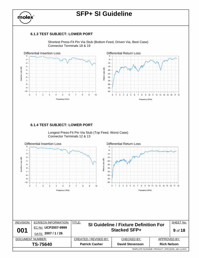
6.1.4 TEST SUBJECT: LOWER PORT
Longest Press-Fit Pin Via Stub (Top Feed, Worst Case) Connector Terminals 12 & 13
Differential Insertion Loss Differential Return Loss

SFP+ SI Guideline
REVISION: ECR/ECN INFORMATION: SHEET No.
EC No: UCP2007-9999 001 DATE: 2007 / 1 / 26
TITLE: SI Guideline / Fixture Definition For Stacked SFP+
10 of 18
DOCUMENT NUMBER: CREATED / REVISED BY: CHECKED BY: APPROVED BY:
TS-75640 Patrick Casher David Stevenson Rich Nelson TEMPLATE FILENAME: PRODUCT_SPEC[SIZE_A](V.1).DOC
7.0 SFP+ CHANNEL ANALYSIS
7.1 CHANNEL DESCRIPTION
- Differential Ports
Port 1 - module end Port 2 - host end
- Molex Connector
Measured s-parameters (4-port, 50MHz to 17.5GHz)
- SFP+ Channel
Agilent Coupled Stripline models
- Simulated PCB Construction
Edge coupled strip-line 25mm trace length for module, 125mm trace length for host board 0.125mm trace width (~5mil) 0.125mm separation (~5mil) 16.7mil dielectric, Nelco 4000-13 0.7mil thick (1/2oz. copper) 0.016 loss tangent
- Simulator
Agilent ADS 2004a
- Channel Description
Reference: SFP+ Specification Revision 4.0
Fibre Channel - Physical Interfaces (FC-PI-3), Revision 1.00, November 29, 2004
125mm Enhanced FR-4
SFP+ ModuleHost Board 25mm Enhanced FR-4
Stacked Connect
SDD11
SDD21

SFP+ SI Guideline
REVISION: ECR/ECN INFORMATION: SHEET No.
EC No: UCP2007-9999 001 DATE: 2007 / 1 / 26
TITLE: SI Guideline / Fixture Definition For Stacked SFP+
11 of 18
DOCUMENT NUMBER: CREATED / REVISED BY: CHECKED BY: APPROVED BY:
TS-75640 Patrick Casher David Stevenson Rich Nelson TEMPLATE FILENAME: PRODUCT_SPEC[SIZE_A](V.1).DOC
7.2 CHANNEL TRANSFER (INSERTION LOSS)
7.2.1 TEST REFERENCE: HOST BOARD AND MODULE CHANNELS COMBINED WITHOUT CONNECTOR
155mm total host channel length
- 125mm printed circuit board length - 30mm for stacked connector lead-frame
25mm module channel length
Comments: A. This example allows a 2.2dB insertion loss margin for a stacked connector and other behavioral discontinuities resulting from PCB channel imperfections (i.e. board fabrication impedance tolerances, routing vias, bga pads, etc ...)
B. 0.5dB loss is informatively budgeted in the specification for a single height connector.
C. The specification does not address the amount of allowable ripple on the insertion loss
curve, especially one that falls right on the compliance curve. Molex's position is that some ripple is tolerable provided that it does not significantly exceed the worst-case insertion loss at the maximum frequency of interest (7GHz).
- 3.8dBat 5.5GHz

SFP+ SI Guideline
REVISION: ECR/ECN INFORMATION: SHEET No.
EC No: UCP2007-9999 001 DATE: 2007 / 1 / 26
TITLE: SI Guideline / Fixture Definition For Stacked SFP+
12 of 18
DOCUMENT NUMBER: CREATED / REVISED BY: CHECKED BY: APPROVED BY:
TS-75640 Patrick Casher David Stevenson Rich Nelson TEMPLATE FILENAME: PRODUCT_SPEC[SIZE_A](V.1).DOC
7.2.2 TEST SUBJECT: UPPER PORT
Shortest Press-Fit Pin Via Stub Longest Press-Fit Pin Via Stub (Bottom Feed, Driven Via, Best Case) (Top Feed, Worst Case) Connector Terminals 12 & 13 Connector Terminals 18 & 19
7.2.3 TEST SUBJECT: LOWER PORT
Shortest Press-Fit Pin Via Stub Longest Press-Fit Pin Via Stub (Bottom Feed, Driven Via, Best Case) (Top Feed, Worst Case) Connector Terminals 18 & 19 Connector Terminals 12 & 13
- 4.7dB at 5.5GHz
- 5.0dB at 5.5GHz
- 4.6dB at 5.5GHz
- 4.8dB at 5.5GHz

SFP+ SI Guideline
REVISION: ECR/ECN INFORMATION: SHEET No.
EC No: UCP2007-9999 001 DATE: 2007 / 1 / 26
TITLE: SI Guideline / Fixture Definition For Stacked SFP+
13 of 18
DOCUMENT NUMBER: CREATED / REVISED BY: CHECKED BY: APPROVED BY:
TS-75640 Patrick Casher David Stevenson Rich Nelson TEMPLATE FILENAME: PRODUCT_SPEC[SIZE_A](V.1).DOC
7.3 CHANNEL RETURN LOSS
7.3.1 TEST SUBJECT: UPPER PORT
Shortest Press-Fit Pin Via Stub Longest Press-Fit Pin Via Stub (Bottom Feed, Driven Via, Best Case) (Top Feed, Worst Case) Connector Terminals 12 & 13 Connector Terminals 18 & 19
7.3.2 TEST SUBJECT: LOWER PORT
Shortest Press-Fit Pin Via Stub Longest Press-Fit Pin Via Stub (Bottom Feed, Driven Via, Best Case) (Top Feed, Worst Case) Connector Terminals 18 & 19 Connector Terminals 12 & 13

SFP+ SI Guideline
REVISION: ECR/ECN INFORMATION: SHEET No.
EC No: UCP2007-9999 001 DATE: 2007 / 1 / 26
TITLE: SI Guideline / Fixture Definition For Stacked SFP+
14 of 18
DOCUMENT NUMBER: CREATED / REVISED BY: CHECKED BY: APPROVED BY:
TS-75640 Patrick Casher David Stevenson Rich Nelson TEMPLATE FILENAME: PRODUCT_SPEC[SIZE_A](V.1).DOC
7.4 EYE COMPLIANCE 7.4.1 CHANNEL DESCRIPTION
- Data Rate =10GB/s
- UI = 100ps
- Reference:
SFP+ Specification Revision 4.0, April 13, 2004 Fibre Channel - Physical Interfaces (FC-PI-3), Revision 1.00,
November 29, 2004
- Pattern
CJTPAT (Fiber Channel–Methodology for Jitter and Signal Quality Specification–MJSQ, INCITs T11.2/Project 1316-DT)
- Transmitter Eye Mask
XFI ASIC/SerDes Transmitter Output Specifications at A trise: 24ps (20-80%) Vlaunch: 180mV Jitter: 0.30UI TJ, 0.15UI DJ
- Receiver Eye Mask
XFI ASIC/SerDes Receiver Input Specifications at D X1: 0.325UI (35ps eye width) Y1: 55mV (110mVpp eye height)
Note: X1 and Y1 are eye mask location indicators called out in the SFP+ specification
- Application Reference Model
The board construction details are identical to those called out in the previous Channel Description section.
170mm Enhanced FR-4
SFP+ ModuleHost Board25mm Enhanced FR-4
ASIC SerDes
Connect
A
D C’
B’ D
C
B

SFP+ SI Guideline
REVISION: ECR/ECN INFORMATION: SHEET No.
EC No: UCP2007-9999 001 DATE: 2007 / 1 / 26
TITLE: SI Guideline / Fixture Definition For Stacked SFP+
15 of 18
DOCUMENT NUMBER: CREATED / REVISED BY: CHECKED BY: APPROVED BY:
TS-75640 Patrick Casher David Stevenson Rich Nelson TEMPLATE FILENAME: PRODUCT_SPEC[SIZE_A](V.1).DOC
7.4.2 TEST SOURCE: STRESSED TRANSMITTER
Eye Height: 355.5 mVpp Eye Width: 73.6ps
7.4.3 TEST SUBJECT: UPPER PORT
Shortest press-fit pin via stub Longest press-fit pin via stub (Bottom Feed, Driven Via, Best Case) (Top Feed, Worst Case) Connector terminals 12 & 13 Connector terminals 18 & 19
Eye Height: 199.9 mVpp Eye Height: 198.5 mVpp Eye Width: 71.4ps Eye Width: 71.8ps

SFP+ SI Guideline
REVISION: ECR/ECN INFORMATION: SHEET No.
EC No: UCP2007-9999 001 DATE: 2007 / 1 / 26
TITLE: SI Guideline / Fixture Definition For Stacked SFP+
16 of 18
DOCUMENT NUMBER: CREATED / REVISED BY: CHECKED BY: APPROVED BY:
TS-75640 Patrick Casher David Stevenson Rich Nelson TEMPLATE FILENAME: PRODUCT_SPEC[SIZE_A](V.1).DOC
7.4.4 TEST SUBJECT: LOWER PORT
Shortest press-fit pin via stub Longest press-fit pin via stub (Bottom Feed, Driven Via, Best Case) (Top Feed, Worst Case) Connector terminals 18 & 19 Connector terminals 12 & 13
Eye Height: 183.0mVpp Eye Height: 191.6mVpp Eye Width: 69.6ps Eye Width: 69.6ps

SFP+ SI Guideline
REVISION: ECR/ECN INFORMATION: SHEET No.
EC No: UCP2007-9999 001 DATE: 2007 / 1 / 26
TITLE: SI Guideline / Fixture Definition For Stacked SFP+
17 of 18
DOCUMENT NUMBER: CREATED / REVISED BY: CHECKED BY: APPROVED BY:
TS-75640 Patrick Casher David Stevenson Rich Nelson TEMPLATE FILENAME: PRODUCT_SPEC[SIZE_A](V.1).DOC
8.0 TEST FIXTURE DESCRIPTION
8.1 FIXTURE COMPONENTS
Host board, Module board
8.2 MATERIAL
Nelco 4000-13SI
8.3 THICKNESS
Board 1.6mm (0.062”) host, 1.0mm (0.040) module Copper 1/2oz. (all layers)
8.4 NUMBER OF LAYERS
6 for the host board, 4 for the module board
8.5 SIGNAL LAYERS
2 & 5 (host board), 1 & 2 (module board)
The signal traces on layer 2 of the host board are designed to provide a worst-case launch condition. They create the longest possible stub effect on the press-fit pin vias for the connector. The signal traces on layer 5 of the host board are designed to provide a best-case launch condition. They create the shortest possible stub effect on the press fit pin vias for the connector.
8.6 TRACE WIDTHS 8mil uncoupled strip-lines (host and module boards) 6mil - 5.5mil - 6mil coupled strip-lines (host board) 13mil micro-strip (module board)
8.7 CALIBRATION STRUCTURES
Worst-Case, Long Stubs
Best-Case, Short Stubs

SFP+ SI Guideline
REVISION: ECR/ECN INFORMATION: SHEET No.
EC No: UCP2007-9999 001 DATE: 2007 / 1 / 26
TITLE: SI Guideline / Fixture Definition For Stacked SFP+
18 of 18
DOCUMENT NUMBER: CREATED / REVISED BY: CHECKED BY: APPROVED BY:
TS-75640 Patrick Casher David Stevenson Rich Nelson TEMPLATE FILENAME: PRODUCT_SPEC[SIZE_A](V.1).DOC
LRM (140MHz max.), TRL (140MHz to 17.5GHz)
8.8 MEASUREMENT REFERENCE PLANE
The on-fixture calibration structures are designed to remove the effects of an SMA and 35mm of uncoupled strip-line trace. These effects are removed on both the host and module portions of the test fixture. After calibration, the measurement reference plane is located at the edge of the connector footprint as defined by the silkscreen on the host board side and 3mm from the contact pads as defined by the silkscreen on the module side.
8.9 TEST FIXTURE FUNCTIONALITY The test boards provide for testing the high-speed transmit and receive pairs as defined in the SFP MSA specification. These pairs are available for connection to test equipment on both the upper port and the lower port of the 2x1 connector. A total of four pairs are provided. Within a port, upper or lower, one pair contains a best-case launch condition and the other a worst-case launch condition. The lower port contains an extra 15mm of coupled stripline traces to route from the measurement reference plane to the front of the connector..
Upper port terminals 12 and 13 best-case condition, terminals 18 and 19 worst-case condition
Lower port terminals 12 and 13 worst-case condition, terminals 18 and 19 best-case condition
Measurement Reference
Measurement Reference