SEWERS PART 1 GENERAL - Brandon, Manitobabrandon.ca/images/pdf/ConstructionSpecs/sewers.pdf ·...
22
City of Brandon Division 2 Standard Construction Specifications Section 02700 January 2000 Page 1 of 22 SEWERS PART 1 GENERAL 1.01 OTHER CONTRACT DOCUMENTS 1.02 DESCRIPTION OF WORK 1.03 RELATED WORK 1.04 CLASSIFICATION OF THE WORK The General Conditions of the Contract, General Requirements, and Supplemental Conditions attached hereto shall apply to and be part of this Section. The Work described herein shall be for the construction of sanitary sewer or land drainage sewer mains, manholes, catch basins, appurtenances and associated works. Section 02210 Excavation Bedding & Backfill Section 02665 Building Connections Sewers shall be classified as either a Sanitary Sewer or a Land Drainage Sewer with each class described on the basis of the conduit size expressed as the nominal inside diameter of the pipe and fittings, on the basis of the type of pipe material, on the basis of the installation depth, and on the basis of the class of trench backfill required. Only one type of pipe shall be used between manholes. Manholes shall be classified as either Type A or Type B with each class described on the basis of the nominal inside diameter of the manhole measured at the invert or base. Unless specified otherwise in Section 01001 Supplemental Conditions or shown on the Drawings, Type A Manholes shall be installed on Sewers 600 millimetres in diameter and smaller and shall have precast floors wherever practicable. Type B manholes shall be installed on sewers 750 millimetres in diameter and larger. Catch basins shall be classified on the basis of the nominal inside diameter of the catch basin measured at the invert of the catch basin, on the basis of the inside depth, and on the basis of the type of inlet casting required. Connections shall be classified on the basis of type of connection being made to a point of discharge.
Transcript of SEWERS PART 1 GENERAL - Brandon, Manitobabrandon.ca/images/pdf/ConstructionSpecs/sewers.pdf ·...

City of Brandon Division 2
Standard Construction Specifications Section 02700
January 2000 Page 1 of 22
SEWERS
PART 1 GENERAL
1.01 OTHER CONTRACT
DOCUMENTS
1.02 DESCRIPTION OF
WORK
1.03 RELATED WORK
1.04 CLASSIFICATION
OF THE WORK
The General Conditions of the Contract, General
Requirements, and Supplemental Conditions attached hereto
shall apply to and be part of this Section.
The Work described herein shall be for the construction of
sanitary sewer or land drainage sewer mains, manholes, catch
basins, appurtenances and associated works.
Section 02210 Excavation Bedding & Backfill
Section 02665 Building Connections
Sewers shall be classified as either a Sanitary Sewer or a Land
Drainage Sewer with each class described on the basis of the
conduit size expressed as the nominal inside diameter of the
pipe and fittings, on the basis of the type of pipe material, on
the basis of the installation depth, and on the basis of the class
of trench backfill required. Only one type of pipe shall be used
between manholes.
Manholes shall be classified as either Type A or Type B
with each class described on the basis of the nominal inside
diameter of the manhole measured at the invert or base.
Unless specified otherwise in Section 01001 Supplemental
Conditions or shown on the Drawings, Type A Manholes shall
be installed on Sewers 600 millimetres in diameter and smaller
and shall have precast floors wherever practicable. Type B
manholes shall be installed on sewers 750 millimetres in
diameter and larger.
Catch basins shall be classified on the basis of the nominal
inside diameter of the catch basin measured at the invert of the
catch basin, on the basis of the inside depth, and on the basis
of the type of inlet casting required.
Connections shall be classified on the basis of type of
connection being made to a point of discharge.
City of Brandon Division 2
Standard Construction Specifications Section 02700
January 2000 Page 2 of 22
SEWERS
PART 2 PRODUCTS
2.01 PVC PIPE &
FITTINGS
2.02 CONCRETE PIPE
& FITTINGS
PVC pipe and fittings shall be Polyvinyl Chloride (PVC)
having a cell classification of 12454B and a minimum pipe
stiffness of 320 kPa. All pipe and fittings shall be
manufactured in accordance with ASTM Standard D 3034
‘Type PSM Poly (Vinyl Chloride)(PVC) Sewer Pipe and
Fittings’ and CAN/CSA-B182.2 ‘PVC Sewer Pipe and Fittings
(PSM Type)’ or CAN/CSA-B182.4 ‘Profile PVC Sewer Pipe
and Fittings’. With the exception of profile walled pipe, all
PVC solid wall pipe shall be DR 35.
Each length of sewer pipe shall have a bell end complete with
a factory installed push on elastomeric ring gasket. Lubricant
for joining pipes shall be approved by the gasket manufacturer.
Pipe shall be coloured green and supplied in lengths not in
excess of 6.1 metres.
PVC fittings, (tees, wyes, bends, reducers and plugs) shall be
injection moulded PVC or fabricated from sections of PVC
pipe of the same, class, type, size and manufacturer as the pipe
to which it joins. Fittings shall be coloured white or green.
Pipe and/or fittings which have been manufactured in excess
of thirty (30) months prior to installation will not be accepted
for incorporation into the Work.
Concrete pipe and fittings shall be manufactured in accordance
with ASTM C 76M ‘Reinforced Concrete, Storm Drain and
Sewer Pipe’,class III, wall B minimum. Acceptance shall be on
the basis of Subsection 5.1.1 of ASTM C 76M. Unless
otherwise specified, pipe joints shall be tongue-and-grove with
each length of pipe supplied complete with a preformed
flexible butyl rubber gasket such as ‘Kent Seal No 2' , ‘Rub’r
Nek’ or approved equal conforming to ASTM C 443M.
Lubricant for joining shall be approved by the gasket
manufacturer. Each length of pipe shall not exceed 3.0 metres
in length and be free of broken pieces of any size, surface
defects of any kind, exposed reinforcing, excessive cracking,
or any crack extending through the entire wall of the pipe.

City of Brandon Division 2
Standard Construction Specifications Section 02700
January 2000 Page 3 of 22
SEWERS
2.03 MANHOLES AND
CATCH BASINS
2:04 MANHOLE FRAME,
COVER &
ADJUSTING RING
CATCH BASIN
INLET
2.05 CONCRETE
Manholes and Catch Basins sections shall be precast concrete
sections manufactured in accordance with ASTM C 478
‘Precast Reinforced Concrete Manhole Sections’. Precast
sections shall be steam cured and shall not be shipped from the
point of manufacture for at least five days after having been
cast.
Each precast section shall be supplied with a preformed
bituminous sealant such as ‘RamNek’ or flexible butyl rubber
joint sealant such as ‘Kent Seal No 2' or approved equal. Each
manhole section shall be supplied complete with 19 millimetre
diameter galvanized steel ladder rungs accurately cast into
each manhole section to from a continuous ladder with rungs
evenly spaced at no more than 325 millimetres on center.
The manufacturer shall provide circular or horseshoe shaped
openings complete with grooved or roughened surfaces for
sewers entering and leaving the manhole. Additional openings
required on the Site shall be made in a manner approved by the
Engineer.
If specified in Section 01001 Supplemental Conditions, the
exterior surface of each manhole section shall be thoroughly
covered with a 12 mil coating of coal tar epoxy type sealant.
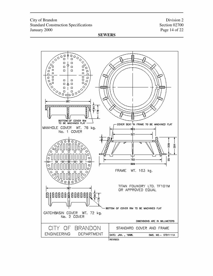
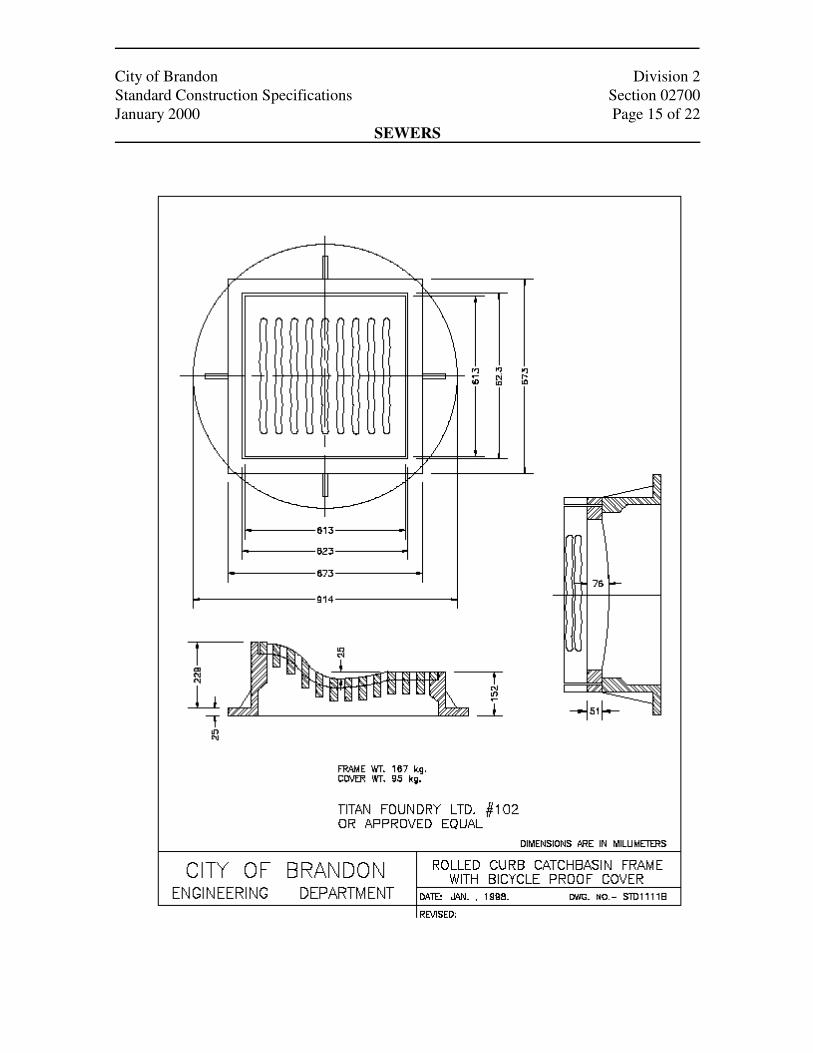
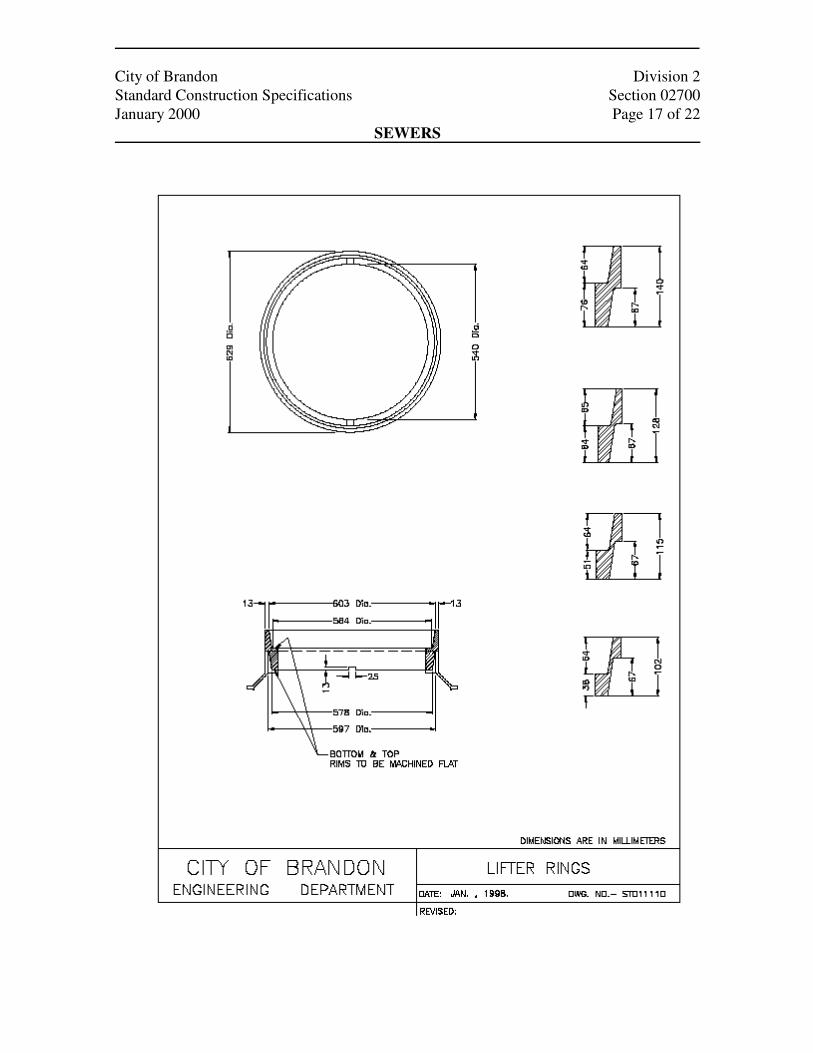
Manhole frame, cover, adjusting rings and Catch Basin inlets
shall be cast of close grained gray iron true to the required
pattern as shown on the Standard Drawings STD
1111A,B,C,D attached to this Section, and shall be smooth,
clean, free of cracks, gas holes, runners, blisters, blow holes,
shrinkage, cold shuts, risers, fins, burnt on sand and other cast
on pieces or flaws. Bearing surfaces shall be clean and shall
provide uniform contact.
Unless stated otherwise in Section 01001 Supplemental
Conditions or shown on the Drawings, Manhole frame and
covers shall be the solid type. Catch Basin inlets shall be as
shown on the Drawings.
Concrete used for pipe, manhole bases, manhole stacks, catch
basins, grouting, benching or flow channels shall be
manufactured using Type 50 sulphate resistant Portland
cement as described in Section 02512, Ready Mixed Concrete.
City of Brandon Division 2
Standard Construction Specifications Section 02700
January 2000 Page 4 of 22
SEWERS
2.06 CEMENT MORTAR
2.07 REINFORCING
STEEL
2.08 SEWER
CONNECTION
COUPLER
2.09 SEWER
CONNECTION
SADDLE
Cement mortar shall consist of equal parts of sulphate resistant
Portland cement and clean sharp mortar sand mixed dry with
only enough water added to make the mixture workable, all in
accordance with Section 02512, Ready Mixed Concrete.
Mortar which has begun to set shall not be used.
Reinforcing steel shall be new deformed bars of intermediate
grade billet steel conforming to the most recent edition of
CAN/CSA-G30.18M ‘Billet-Steel Bars for Concrete
Reinforcement’.
Sewer Connection Coupler used to connect two pipes of
similar or dissimilar material shall have rubber gasket joints.
The manufacturer of the coupler must specifically state the
coupler will provide a sound and watertight connection
between the two pipes being connected. A rubber gasket slip-
on coupler will be allowed for PVC to PVC connections only,
all other types of connections shall use a flexible rubber
coupling such as a ‘Fernco Tridon Coupling Adaptor’ or
approved equal. A coupler requiring a solvent sealed joint will
not be permitted.
Sewer Connection Saddle shall be a PVC plastic strap on
saddle complete with rubber gasket and two all stainless steel
worm drive clamps or straps. The Sewer Connection Saddle
shall be of a type and size to suit the Sewer Connection pipe
material to which it is being installed.

City of Brandon Division 2
Standard Construction Specifications Section 02700
January 2000 Page 5 of 22
SEWERS
PART 3 EXECUTION
3.01 LINE AND GRADE
3.02 TOLERANCES
3:03 SEWAGE HANDLING
At each proposed manhole/outfall location, the Engineer will
establish offset hubs for horizontal control and provide a grade
on a minimum of one hub for vertical control. Prior to
commencing any Work the Contractor shall satisfy himself as
to the meaning and correctness of all hubs, no claims shall be
made for any alleged inaccuracies because of his failure to
read same correctly. The Contractor shall maintain all hubs in
good order and transfer the correct horizontal and vertical
control to the sewer invert(s) in the manhole.
The use of a laser is required to maintain line and grade. The
laser shall be set within a manhole and emit its light beam
through the interior of the pipe. If bending of the beam due to
air temperature variations or dust in the air is apparent within
the pipe, a fan shall be provided to circulate the air. Air
velocity shall not be so excessive as to cause pulsating or
vibrating of the beam. Pipe laying shall not commence until
the laser setup has been approved by the Engineer. The
Contractor shall follow the manufacture's instructions for the
laser’s use and ensure that a qualified operator handle the
equipment during the course of construction. If, in the opinion
of the Engineer, the Contractor's method of setting grade is
inaccurate or insufficient, the Engineer may direct that a more
suitable method be used to ensure that accurate grade and /or
alignment is maintained.
Sewer pipe, fittings, appurtenances, manholes and catch basins
shall be installed accurately to the required line and grade
shown on the Drawings or as set on the Site the Engineer.
Vertical and horizontal variance from line shall not exceed 12
millimetres. There shall be no dips which will allow ponding
of water to a depth of more than 25 millimetres. Sharp bends
will not be permitted even thought the pipe remains within
these tolerances.
The Contractor shall supply, operate and maintain all
necessary equipment to ensure the continuous operation of the
existing sewage collection system. Under NO circumstances
shall raw sewage be discharged onto land, streets or into
ditches,
City of Brandon Division 2
Standard Construction Specifications Section 02700
January 2000 Page 6 of 22
SEWERS
3.04 EXCAVATION
3.05 INSTALLATION
OF PIPE
streams, lakes, or water courses during the performance and
execution of the Work. Where existing sewers carrying
sanitary sewage are encountered, the Contractor shall supply,
install and maintain temporary connection and pumping
facilities as required by the Engineer in order to prevent any
nuisance.
Excavation shall be in accordance with Section 02210,
Excavation Bedding & Backfill.
Each section of pipe shall be accurately placed on a dry, firm
but slightly yielding foundation of bedding material to the line
and grade stated in Parts 3.01 and 3.02 and backfilled as
described in Section 02210 Excavation Bedding & Backfill.
Pipe laying shall proceed upgrade beginning at the lowest
elevation of the length being laid with the spigot end of each
pipe pointing in the direction of the flow.
All sewer pipe and fittings shall be joined using elastomeric
gaskets and in strict accordance with the pipe manufacturer's
printed assembly instructions to form a watertight connection
with the adjoining pipe. Prior to joining pipes, the Contractor
shall obtain the approval of the Engineer for the method to be
used and, if requested, shall demonstrate, his ability to carry
out the method proposed. Extreme care should be taken during
joining to insure that all interior and joining surfaces are clean
and free of any foreign materials. Displaced or contaminated
gaskets shall be removed, cleaned and lubricated or replaced
prior to joining. Pipes shall be carefully aligned and inserted
by hand, bar and wooden block, lever type or friction pullers.
The use of hydraulic excavation equipment as the means of
pushing or moving the pipe to grade will not be permitted.
Each joint shall be satisfactorily completed prior to installation
of the next length of pipe.
The Contractor shall cut pipe with a fine toothed hand saw,
power saw, hack saw, or disk cutter, but not with a chain saw.
The spigot end of solid wall PVC pipe shall be bevelled.
At the end of each workday, or when sewer pipe is not being
installed, the open end of the pipe shall be protected by a close

City of Brandon Division 2
Standard Construction Specifications Section 02700
January 2000 Page 7 of 22
SEWERS
3.06 BEND AND CURVES
ON SEWER MAINS
3.07 MANHOLES
fitting stopper to keep the pipe clean, with adequate
precautions taken to overcome possible uplift.
All lift holes in concrete pipe shall be plugged with concrete
mortar and, on pipes 750 millimetres in diameter and larger,
they shall be trowelled smooth and flush with the inside face
of the pipe.
The Contractor will not be permitted to deflect straight pipe
sections to create curves or correct alignment errors. Curves
and bends on pipes shall be made with either radius pipe or
approved fittings.
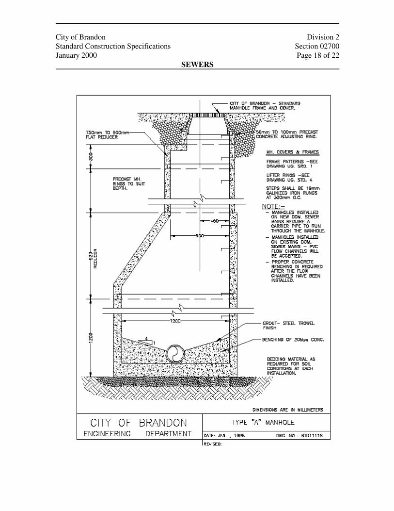
Manholes shall be installed at the locations shown on the
Drawings, as directed by the Engineer, or as specified in
Section 01001 Supplemental Conditions all in accordance with
the Standard Drawings STD 1111Q,R,S attached to this
Section, or as detailed on the Drawings.
Each manhole base shall rest on 150 millimetres of foundation
stone. As an alternative to a precast manhole base, the
Contractor may use an open base to straddle an existing
sewer(s) with the base floor cast in place after the reinforcing
has been placed as required for a precast manhole.
Each precast concrete manhole section including adjustment
ring(s) shall be joined using a preformed bituminous sealant
installed on the tongue end of each manhole to form a
continuous watertight joint. Sections shall be lowered with
care and properly aligned to ensure ladder rungs line up
vertically. All joints and lifting holes shall be sealed on the
inside and outside with grout to form a watertight installation.
All PVC pipe entering a manhole shall have a manhole water
stop gasket installed firmly clamped around the pipe at the
manhole. If a flexible entry is used the, water stop gasket is not
required and the PVC sewer pipe shall be installed completely
through the manhole with a continuous slope from the inlet to
the outlet side(s). The Contractor shall ensure a suitable bond
is obtained between the PVC pipe and the concrete by coating
the PVC pipe with an epoxy and applying a select granular
material (sand) to the epoxy which shall be allowed to harden
City of Brandon Division 2
Standard Construction Specifications Section 02700
January 2000 Page 8 of 22
SEWERS
3.08 CONNECTION TO
EXISTING SEWER
prior to grouting the pipe into the manhole. As an alternative,
the Contractor shall install a manhole adaptor grouted into
place to ensure a flexible water tight connection.
Concrete benching and flow channels shall be constructed
provided as shown on the Drawings and as directed by the
Engineer. After benching of the manhole is complete the top
portion of the pipe shall be removed at the spring line by
neatly cutting the pipe lengthwise such that a semi circular
pipe is created. With concrete pipe, channels shall be formed
and cast in concrete to the spring line of the connecting pipe.
The finished invert shall be a semi circular shaped smooth
channel directing the flow to the downstream sewer.
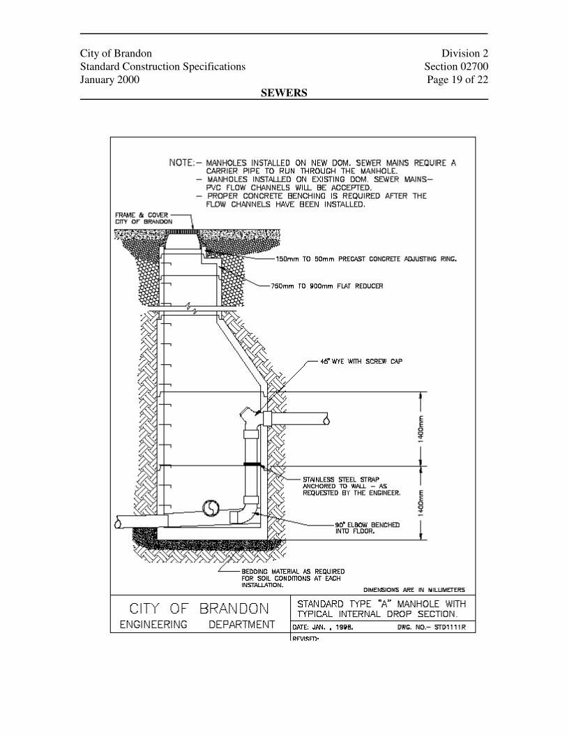
Drop inlets shall be constructed as shown on the Drawings and
the Standard Drawing STD 1111 R attached to this Section.
Unless otherwise specified in the Section 01001 Supplemental
Conditions, the completed manhole shall be backfilled with
Granular Backfill as described in Section 02210, Excavation,
Bedding & Backfill, a minimum distance of 1 metre from the
side of the manhole.
The cast iron cover frame shall be supported on at least one (1)
150 millimetre deep precast concrete adjusting ring and sealed
to the adjusting ring by a preformed bituminous sealant placed
between the cover frame and the concrete. The frame and
cover shall be set level with the finished grade elevation as
shown on the Drawings, or as directed by the Engineer, and if
required shall be temporarily ramped with earth or gravel.
Prior to connecting to an existing sewer the Contractor shall
provide adequate means, such as a dam in a downstream
manhole, to prevent soil, silt, gravel or debris from entering
the existing sewer system.
The plug shall be removed from the existing sewer. Any debris
which collects in a new or existing main as a result of the
Contractor's operations shall be removed and all pipes left
clean and unobstructed. A new gasket shall be installed in the

City of Brandon Division 2
Standard Construction Specifications Section 02700
January 2000 Page 9 of 22
SEWERS
3.09 CONNECTION TO
EXISTING
MANHOLE
3.10 CATCH BASIN
bell or grove of the existing pipe and the new pipe installed as
stated in Part 3.05 of this Section. If the new pipe is of a
different material than the existing pipe, an approved sewer
connection coupler shall be installed in strict accordance with
the coupler manufacturer's printed assembly instructions. Any
damage to the existing sewer shall be promptly repaired at the
Contractor’s sole expense.
Prior to connecting to an existing manhole the Contractor shall
provide adequate means, such as a dam in the downstream
invert, to prevent soil, silt, gravel or debris from entering the
existing sewer system. The wall of the existing manhole shall
be exposed by excavation and a jackhammer or sledge hammer
used to carefully break an opening in the manhole wall where
the new pipe invert is located. Any damage to the existing
manhole shall be promptly repaired at the Contractor’s sole
expense. The reinforcing mesh shall be cut and removed along
with the rubble and disposed of as directed by the Engineer. If
a semi circular channel does not already exist in the bottom of
the manhole, one shall be installed by removing the existing
concrete benching and installing a new PVC or concrete flow
channel as described in Part 3:07 of this Section. Any debris
which collects in the manhole as a result of the Contractor's
operations shall be removed and all flow channels and inverts
left clean and unobstructed.
The catch basin shall be installed and connected at the
locations shown on the Drawings, as directed by the Engineer,
or as specified in Section 01001 Supplemental Conditions all
in accordance with the Standard Drawings STD 1111P
attached to this Section and as detailed on the Drawings. Catch
basin leads between single and multiple catch basins and a
land drainage sewer shall be 300 millimetre Class III
reinforced concrete pipe with rubber gasket joints unless
shown otherwise on the Drawings or specified in Section
01001 Supplemental Conditions.
Catch basin leads shall be installed as described in Part 2.05 of
this Section. The outlet pipe shall be trimmed such that it
opens flush with the inside wall of the catch basin. Where an
existing catch basin lead is moved from a sanitary to a land

City of Brandon Division 2
Standard Construction Specifications Section 02700
January 2000 Page 10 of 22
SEWERS
3.11 ABANDONED
WORKS
3.12 SEWER CLEANING
drainage sewer, the Contractor shall, if possible, reuse the
existing catch basin outlet when installing the new storm water
leads. Abandoned lead outlets in catch basins, manholes and
the disconnected pipe ends shall be plugged and made water-
tight. Where an existing catch basin reconnected to a land
drainage sewer has leads smaller than 300 millimetres in
diameter, the Contractor shall enlarge the pipe openings in
both the existing catch basin and manhole and install the size
of lead specified or shown on the Drawings. The Engineer may
permit an existing 250 millimetre lead to remain in place.
The casting frame shall be sealed to the reducer by a
preformed bituminous sealant placed between the inlet frame
and the concrete to provide a watertight joint. The cast inlet
frame shall be set level with the finished grade elevation as
shown on the Drawings, or as directed by the Engineer, and if
required shall be temporarily ramped with earth or gravel.
The Contractor shall seal all abandoned sewers not removed
during the course of construction by placing a minimum length
of 500 millimetres of 10.5 MPa concrete into the end of each
abandoned sewer(s),including any unused inverts in manholes
and catch basins, forming a complete seal.
Abandoned manholes shall have the upper rings or rows of
bricks removed to a depth of 1.2 metres below the finished
grade. The remainder of the manhole shall be filled with
compacted select granular material and buried. Catch basins
shall be completely removed with the open excavation filled
with compacted select granular material and buried. All
salvaged manhole and inlet frames and covers removed by the
Contractor shall be stockpiled and delivered to the City.
The sewer pipe and manhole(s) shall be throughly cleaned
upon completion of the Work and prior to deflection testing or
television inspection. The sewer and manhole(s) shall be
cleaned with high velocity sewer cleaning equipment which
shall remove all foreign materials from the sewer and related
structures. Precautions shall be taken by the Contractor to
ensure that the water pressure created does not damage or
cause flooding of public or private property being served by
the sewer. All dirt, sand, rocks, grease and other solid or

City of Brandon Division 2
Standard Construction Specifications Section 02700
January 2000 Page 11 of 22
SEWERS
3.13 SEWER TESTING
3.14 DEFLECTION
TESTING
semisolid material resulting form the cleaning operation shall
be removed at the downstream manhole of the section being
cleaned and disposed of as directed by the Engineer. Passing
material from manhole section to manhole section will not be
permitted.
Acceptance of the sewer cleaning shall be made upon the
successful completion of the television inspection and shall be
to the satisfaction of the Engineer. If the television inspection
shows the cleaning to be unsatisfactory, the Contractor shall be
required to again and televise the sewer until the cleaning is
shown to be satisfactory.
All tests and television inspection shall be carried out from
manhole to manhole as directed by the Engineer. Testing shall
not be carried out until a period of at least two (2) weeks has
expired after well-point de-watering has ceased. Deflection
testing may be conducted in conjunction with the television
inspection however the sewer jet shall not be in operation
during the television inspection.
All PVC sewers shall be tested for deflection using a rigid
mandrel sized to pass a maximum deflection(deformation of
the pipe diameter) of 5%. No allowance shall be made for pipe
wall thickness tolerances or out of round due to heat, shipping,
or other external cause. The inspection shall be conducted no
earlier than thirty (30) calendar days after the backfill has been
placed to final grade, and provided in the opinion of the
Engineer that sufficient water densification or rainfall has
occurred to thoroughly settle the soil throughout the entire
trench depth. If densification cannot be achieved in the time
after installation of the pipe and backfill prior to the project
completion date, then the mandrel size shall be increased to
pass a maximum deflection of 4%.
The mandrel shall be carefully pulled through the sewer by the
Contractor. Any sections of sewer that does not allow the
mandrel to pass shall be considered to have failed the
deflection test and shall be uncovered, repaired or replaced at
the Contractor’s sole expense and the section tested again.
City of Brandon Division 2
Standard Construction Specifications Section 02700
January 2000 Page 12 of 22
SEWERS
3.15 TELEVISION
INSPECTION
3.16 INFILTRATION TEST
3.17 EXFILTRATION
TEST
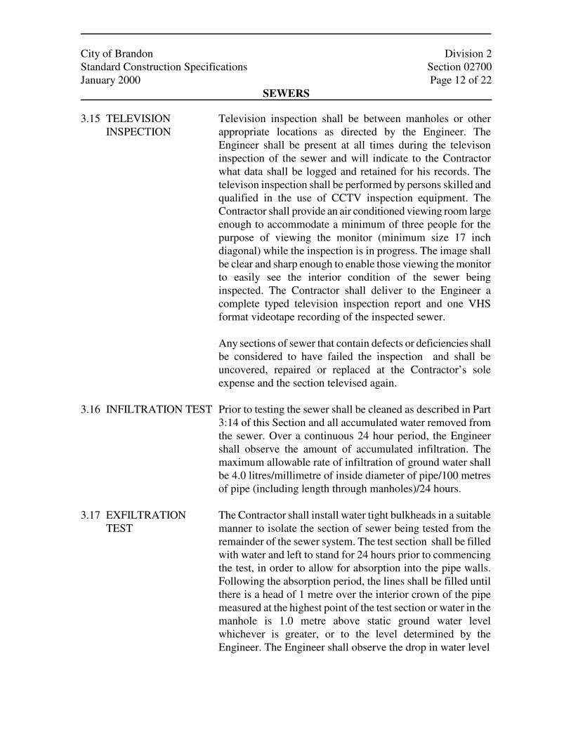
Television inspection shall be between manholes or other
appropriate locations as directed by the Engineer. The
Engineer shall be present at all times during the televison
inspection of the sewer and will indicate to the Contractor
what data shall be logged and retained for his records. The
televison inspection shall be performed by persons skilled and
qualified in the use of CCTV inspection equipment. The
Contractor shall provide an air conditioned viewing room large
enough to accommodate a minimum of three people for the
purpose of viewing the monitor (minimum size 17 inch
diagonal) while the inspection is in progress. The image shall
be clear and sharp enough to enable those viewing the monitor
to easily see the interior condition of the sewer being
inspected. The Contractor shall deliver to the Engineer a
complete typed television inspection report and one VHS
format videotape recording of the inspected sewer.
Any sections of sewer that contain defects or deficiencies shall
be considered to have failed the inspection and shall be
uncovered, repaired or replaced at the Contractor’s sole
expense and the section televised again.
Prior to testing the sewer shall be cleaned as described in Part
3:14 of this Section and all accumulated water removed from
the sewer. Over a continuous 24 hour period, the Engineer
shall observe the amount of accumulated infiltration. The
maximum allowable rate of infiltration of ground water shall
be 4.0 litres/millimetre of inside diameter of pipe/100 metres
of pipe (including length through manholes)/24 hours.
The Contractor shall install water tight bulkheads in a suitable
manner to isolate the section of sewer being tested from the
remainder of the sewer system. The test section shall be filled
with water and left to stand for 24 hours prior to commencing
the test, in order to allow for absorption into the pipe walls.
Following the absorption period, the lines shall be filled until
there is a head of 1 metre over the interior crown of the pipe
measured at the highest point of the test section or water in the
manhole is 1.0 metre above static ground water level
whichever is greater, or to the level determined by the
Engineer. The Engineer shall observe the drop in water level
City of Brandon Division 2
Standard Construction Specifications Section 02700
January 2000 Page 13 of 22
SEWERS
over a 2 hour period. The maximum rate of leakage shall be
0.20 litres/ millimetre of inside diameter of pipe/100 metres of
pipe/ hour. An additional 3.0 litres/hour/vertical metre of
manhole riser above the invert shall be allowed for leakage
through manholes. If hydrostatic testing reveals excessive
leakage, the Contractor shall repair the defective lines and the
test shall be repeated until leakage falls within the allowable
limit.
City of Brandon Division 2
Standard Construction Specifications Section 02700
January 2000 Page 14 of 22
SEWERS
City of Brandon Division 2
Standard Construction Specifications Section 02700
January 2000 Page 15 of 22
SEWERS

City of Brandon Division 2
Standard Construction Specifications Section 02700
January 2000 Page 16 of 22
SEWERS
City of Brandon Division 2
Standard Construction Specifications Section 02700
January 2000 Page 17 of 22
SEWERS
City of Brandon Division 2
Standard Construction Specifications Section 02700
January 2000 Page 18 of 22
SEWERS
City of Brandon Division 2
Standard Construction Specifications Section 02700
January 2000 Page 19 of 22
SEWERS

City of Brandon Division 2
Standard Construction Specifications Section 02700
January 2000 Page 20 of 22
SEWERS

City of Brandon Division 2
Standard Construction Specifications Section 02700
January 2000 Page 21 of 22
SEWERS
City of Brandon Division 2
Standard Construction Specifications Section 02700
January 2000 Page 22 of 22
SEWERS
END OF SECTION