UHMWPE- Ultra high molecular weight polyethylene__as a biomaterial
INSTRUCTIONS–PARTS LIST 308-116Rev B
Supersedes AThis manual contains IMPORT ANTWARNINGS AND INSTRUCTIONS
READ AND RETAIN FOR REFERENCE
SEVERE–DUTY, UHMWPE/TEFLON� PACKED
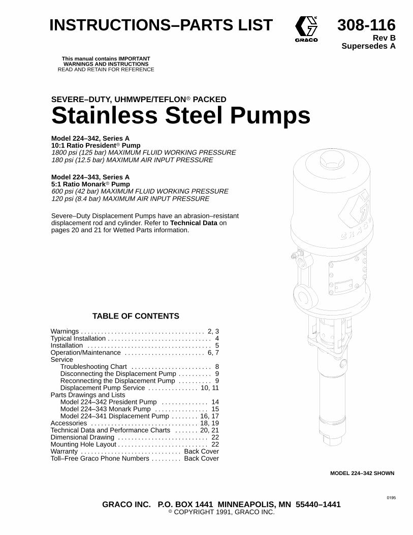
Stainless Steel PumpsModel 224–342, Series A 10:1 Ratio President � Pump1800 psi (125 bar) MAXIMUM FLUID WORKING PRESSURE180 psi (12.5 bar) MAXIMUM AIR INPUT PRESSURE
Model 224–343, Series A 5:1 Ratio Monark � Pump600 psi (42 bar) MAXIMUM FLUID WORKING PRESSURE120 psi (8.4 bar) MAXIMUM AIR INPUT PRESSURE
Severe–Duty Displacement Pumps have an abrasion–resistant displacement rod and cylinder. Refer to Technical Data on pages 20 and 21 for Wetted Parts information.
GRACO INC. P.O. BOX 1441 MINNEAPOLIS, MN 55440–1441� COPYRIGHT 1991, GRACO INC.
TABLE OF CONTENTS
Warnings 2, 3. . . . . . . . . . . . . . . . . . . . . . . . . . . . . . . . . . . . . Typical Installation 4. . . . . . . . . . . . . . . . . . . . . . . . . . . . . . . Installation 5. . . . . . . . . . . . . . . . . . . . . . . . . . . . . . . . . . . . . Operation/Maintenance 6, 7. . . . . . . . . . . . . . . . . . . . . . . . Service
Troubleshooting Chart 8. . . . . . . . . . . . . . . . . . . . . . . . Disconnecting the Displacement Pump 9. . . . . . . . . . Reconnecting the Displacement Pump 9. . . . . . . . . . Displacement Pump Service 10, 11. . . . . . . . . . . . . . .
Parts Drawings and ListsModel 224–342 President Pump 14. . . . . . . . . . . . . . Model 224–343 Monark Pump 15. . . . . . . . . . . . . . . . Model 224–341 Displacement Pump 16, 17. . . . . . . .
Accessories 18, 19. . . . . . . . . . . . . . . . . . . . . . . . . . . . . . . . Technical Data and Performance Charts 20, 21. . . . . . . Dimensional Drawing 22. . . . . . . . . . . . . . . . . . . . . . . . . . . Mounting Hole Layout 22. . . . . . . . . . . . . . . . . . . . . . . . . . . Warranty Back Cover. . . . . . . . . . . . . . . . . . . . . . . . . . . . . . Toll–Free Graco Phone Numbers Back Cover. . . . . . . . .
MODEL 224–342 SHOWN
����

� �������
SAFETY WARNINGSHIGH PRESSURE FLUID CAN CAUSE SERIOUS INJUR Y. FOR PROFESSIONAL USE ONLY.
OBSERVE ALL WARNINGS. Read And Understand All Instruction Manuals Before Operating Equipment.
FLUID INJECTION HAZARDGeneral SafetyThis equipment generates very high fluid pressure. Spray from the spraygun, leaks or ruptured components can inject fluid through your skin andinto your body and cause extremely serious bodily injury, including theneed for amputation. Also, fluid injected or splashed into the eyes or onthe skin can cause serious damage.
NEVER point the spray gun at anyone or at any part of the body. NEVERput hand or fingers over the spray tip.
ALWAYS have the tip guard in place on the spray gun when spraying.
ALWAYS follow the Pressure Relief Procedure , right, before cleaningor removing the spray tip or servicing any system equipment.
NEVER try to stop or deflect leaks with your hand or body.
Be sure all equipment safety devices are operating properly before eachuse.
Medical Alert––Airless Spray W oundsIf any fluid appears to penetrate your skin, get EMERGENCY MEDICALCARE AT ONCE. DO NOT TREAT AS A SIMPLE CUT. Tell the doctorexactly what fluid was injected.
Note to Physician: Injection in the skin is a traumatic injury. It is im -portant to treat the injury surgically as soon as possible . Do notdelay treatment to research toxicity. Toxicity is a concern with some ex-otic coatings injected directly into the blood stream. Consultation with aplastic surgeon or reconstructive hand surgeon may be advisable.
Spray Gun Safety DevicesBe sure all spray gun safety devices are operating properly before eachuse. Do not remove or modify any part of the gun; this can cause a mal-function and result in serious bodily injury.
Safety LatchWhenever you stop spraying, even for a moment, always set the spraygun safety latch in the closed or “safe” position, making the gun inopera-tive. Failure to set the safety latch can result in accidental triggering of thegun.
Trigger GuardNever operate the spray gun with the trigger guard removed. This guardhelps prevent the gun from triggering accidentally if it is dropped orbumped.
DiffuserThe spray gun diffuser breaks up spray and reduces the risk of fluid injec-tion when the tip is not installed. Check the diffuser operation regularly.Follow the Pressure Relief Procedure , below, then remove the spraytip. Aim the spray gun into a grounded metal pail, holding the spray gunfirmly to the pail. Using the lowest possible pressure, trigger the spraygun. If the fluid emitted is not diffused into an irregular stream, replace thediffuser immediately.
Tip GuardALWAYS have the tip guard in place on the spray gun while spraying. Thetip guard alerts you to the fluid injection hazard and helps reduce, butdoes not prevent, the risk of accidentally placing your fingers or any partof your body close to the spray tip.
Spray T ip SafetyUse extreme caution when cleaning or changing spray tips. If the spraytip clogs while spraying, engage the spray gun safety latch immediately.ALWAYS follow the Pressure Relief Procedure and then remove thespray tip to clean it.
NEVER wipe off build–up around the spray tip until pressure is fully re-lieved and the spray gun safety latch is engaged.
Pressure Relief ProcedureTo reduce the risk of serious bodily injury, including fluid injection,splashing in the eyes or on the skin, or injury from moving parts,always follow this procedure whenever you shut off the pump,when checking or servicing any part of the spray system, when in-stalling, cleaning or changing spray tips, and whenever you stopspraying.
1. Engage the spray gun safety latch.2. Shut off the air to the pump.3. Close the bleed–type master air valve (required in your sys-
tem).4. Disengage the gun safety latch.5. Hold a metal part of the gun firmly to the side of a grounded
metal pail, and trigger the gun to relieve pressure.6. Engage the gun safety latch.7. Open the drain valve (required in your system), having a
grounded metal container ready to catch the drainage.8. Leave the drain valve open until you are ready to spray again.If you suspect that the spray tip or hose is completely clogged, orthat pressure has not been fully relieved after following the stepsabove, VERY SLOWLY loosen the tip guard retaining nut or hoseend coupling and relieve pressure gradually, then loosen com-pletely. Now clear the tip or hose.
EQUIPMENT MISUSE HAZARDGeneral SafetyAny misuse of the spray equipment or accessories, such asoverpressurizing, modifying parts, using incompatible chemicals and flu-ids, or using worn or damaged parts, can cause them to rupture and resultin fluid injection, splashing in the eyes or on the skin, or other serious bod-ily injury, or fire, explosion or property damage.
NEVER alter or modify any part of this equipment; doing so could cause itto malfunction.
CHECK all spray equipment regularly and repair or replace worn or dam-aged parts immediately.
Always wear protective eyewear, gloves, clothing and respirator as rec-ommended by the fluid and solvent manufacturer.
System PressureNEVER exceed the recommended fluid working pressure or the maxi-mum air inlet pressure stated on your pump or in the TECHNICAL DATAon pages 20 and 21.
Be sure that all spray equipment and accessories are rated to withstandthe maximum working pressure of the pump. DO NOT exceed the maxi-mum working pressure of any component or accessory used in the sys-tem.
Fluid CompatibilityBE SURE that all fluids and solvents used are chemically compatible withthe wetted parts shown in the TECHNICAL DATA on pages 20 and 21.Always read the manufacturer’s literature before using fluid or solvent inthis pump.
������� �
FIRE OR EXPLOSION HAZARDStatic electricity is created by the high velocity flow of fluid through thepump and hose. If every part of the spray equipment is not properlygrounded, sparking may occur, and the system may become hazardous.Sparking may also occur when plugging in or unplugging a power supplycord. Sparks can ignite fumes from solvents and the fluid being sprayed,dust particles and other flammable substances, whether you are spray-ing indoors or outdoors, and can cause a fire or explosion and seriousbodily injury and property damage. Do not plug in or unplug any powersupply cords in the spray area when there is any chance of igniting fumesstill in the air.
If you experience any static sparking or even a slight shock while usingthis equipment, STOP SPRAYING IMMEDIATELY. Check the entire sys-tem for proper grounding. Do not use the system again until the problemhas been identified and corrected.
GroundingTo reduce the risk of static sparking, ground the pump, object beingsprayed, and all other spray equipment used or located in the spray area.CHECK your local electrical code for detailed grounding instructions foryour area and type of equipment. BE SURE to ground all of this sprayequipment:
1. Pump: use a ground wire and clamp. See Fig 1.
2. Air and fluid hoses: use only grounded hoses with a maximum of500 ft (150 m) combined hose length to ensure grounding continuity.Refer to Hose Grounding Continuity .
3. Air compressor: follow manufacturer’s recommendations.
4. Spray gun: grounding is obtained through connection to a properlygrounded fluid hose and pump.
5. Object being sprayed: according to your local code.
6. Fluid supply container: according to your local code.
7. All solvent pails used when flushing, according to your local code.Use only metal pails, which are conductive, placed on a groundedsurface. Do not place the pail on a nonconductive surface, such aspaper or cardboard, which interrupts the grounding continuity.
8. To maintain grounding continuity when flushing or relieving pres-sure, always hold a metal part of the spray gun firmly to the side of agrounded metal pail, then trigger the gun.
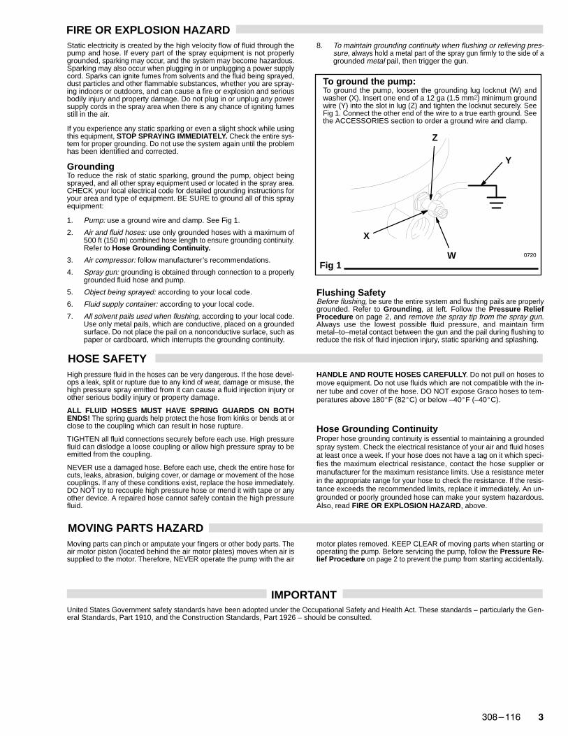
To ground the pump:To ground the pump, loosen the grounding lug locknut (W) andwasher (X). Insert one end of a 12 ga (1.5 mm�) minimum groundwire (Y) into the slot in lug (Z) and tighten the locknut securely. SeeFig 1. Connect the other end of the wire to a true earth ground. Seethe ACCESSORIES section to order a ground wire and clamp.
Fig 1W
Y
X
Z
����
Flushing SafetyBefore flushing, be sure the entire system and flushing pails are properlygrounded. Refer to Grounding , at left. Follow the Pressure ReliefProcedure on page 2, and remove the spray tip from the spray gun.Always use the lowest possible fluid pressure, and maintain firmmetal–to–metal contact between the gun and the pail during flushing toreduce the risk of fluid injection injury, static sparking and splashing.
HOSE SAFETYHigh pressure fluid in the hoses can be very dangerous. If the hose devel-ops a leak, split or rupture due to any kind of wear, damage or misuse, thehigh pressure spray emitted from it can cause a fluid injection injury orother serious bodily injury or property damage.
ALL FLUID HOSES MUST HAVE SPRING GUARDS ON BOTHENDS! The spring guards help protect the hose from kinks or bends at orclose to the coupling which can result in hose rupture.
TIGHTEN all fluid connections securely before each use. High pressurefluid can dislodge a loose coupling or allow high pressure spray to beemitted from the coupling.
NEVER use a damaged hose. Before each use, check the entire hose forcuts, leaks, abrasion, bulging cover, or damage or movement of the hosecouplings. If any of these conditions exist, replace the hose immediately.DO NOT try to recouple high pressure hose or mend it with tape or anyother device. A repaired hose cannot safely contain the high pressurefluid.
HANDLE AND ROUTE HOSES CAREFULLY. Do not pull on hoses tomove equipment. Do not use fluids which are not compatible with the in-ner tube and cover of the hose. DO NOT expose Graco hoses to tem-peratures above 180�F (82�C) or below –40�F (–40�C).
Hose Grounding ContinuityProper hose grounding continuity is essential to maintaining a groundedspray system. Check the electrical resistance of your air and fluid hosesat least once a week. If your hose does not have a tag on it which speci-fies the maximum electrical resistance, contact the hose supplier ormanufacturer for the maximum resistance limits. Use a resistance meterin the appropriate range for your hose to check the resistance. If the resis-tance exceeds the recommended limits, replace it immediately. An un-grounded or poorly grounded hose can make your system hazardous.Also, read FIRE OR EXPLOSION HAZARD , above.
MOVING PARTS HAZARDMoving parts can pinch or amputate your fingers or other body parts. Theair motor piston (located behind the air motor plates) moves when air issupplied to the motor. Therefore, NEVER operate the pump with the air
motor plates removed. KEEP CLEAR of moving parts when starting oroperating the pump. Before servicing the pump, follow the Pressure Re -lief Procedure on page 2 to prevent the pump from starting accidentally.
IMPORTANTUnited States Government safety standards have been adopted under the Occupational Safety and Health Act. These standards – particularly the Gen-eral Standards, Part 1910, and the Construction Standards, Part 1926 – should be consulted.

� �������
TYPICAL INSTALLATION
KEY
A PumpB Pump Runaway ValveC Air Line LubricatorD Bleed–Type Master Air Valve (required, for pump)E Pump Air RegulatorF Air Line FilterG Bleed–Type Master Air Valve (for accessories)H Air Supply HoseJ Fluid Drain Valve (required)K Fluid FilterL Fluid Supply HoseM Spray GunN Fluid Suction HoseP Wall BracketY Ground Wire (required; see page 3
for installation instructions)
J
A
B
C D
E F G
H
K
L
M
N
Y
P
����
������� �
INSTALLATION
NOTE: Reference numbers and letters in parenthesesin the text refer to the callouts in the figures andthe parts drawing.
See pages 18 and 19 for accessories availablefrom Graco. If you supply your own accessories,be sure they are adequately sized and pressure–rated to meet the system’s requirements.
The Typical Installation shown on page 4 is only a guidefor selecting and installing system components and ac-cessories. Contact your Graco representative or GracoTechnical Assistance (see back page) for assistance indesigning a system to suit your particular needs.
SYSTEM ACCESSORIES
Refer to the Typical Installation drawing on page 4.
A bleed–type master air valve (D) and a fluid drainvalve (J) are required in your system. These acces-sories help reduce the risk of serious bodily injuryincluding fluid injection, splashing in the eyes or onthe skin, and injury from moving parts if you are ad-justing or repairing the pump.
The bleed–type master air valve relieves airtrapped between this valve and the pump after theair is shut off. Trapped air can cause the pump tocycle unexpectedly. Locate the valve close to thepump.
The fluid drain valve assists in relieving fluid pres-sure in the displacement pump, hose, and gun.Triggering the gun to relieve pressure may not besufficient.
WARNING
Mounting Accessories
Mount the pump (A) to suit the type of installationplanned. The pump dimensions and mounting hole lay-out are shown on page 22.
Air and Fluid Hoses
Be sure all air and fluid hoses are properly sized andpressure–rated for your system. Use only grounded airand fluid hoses. Fluid hoses must have spring guards onboth ends.
Connect a grounded fluid hose (L) to the pump’s fluid out-let.
Connect a fluid suction hose (N) to the pump’s 3/4 npt(f)fluid intake.
Use a grounded 1/2 in. I.D. (minimum) air hose (H) tosupply air to the pump.
Air Line Accessories
Install the following accessories in the order shown in theTypical Installation, using adapters as necessary:
An air line lubricator (C) provides automatic air mo-tor lubrication.
A bleed–type master air valve (D) is required in yoursystem to relieve air trapped between it and the airmotor when the valve is closed (see the WARNING atleft). Be sure the bleed valve is easily accessible fromthe pump, and is located downstream from the airregulator.
A pump runaway valve (B) senses when the pumpis running too fast and automatically shuts off the air tothe motor. A pump which runs too fast can be serious-ly damaged.
An air regulator (E) controls pump speed and outletpressure by adjusting the air pressure to the pump.Locate the regulator close to the pump, but upstreamfrom the bleed–type master air valve.
An air line filter (F) removes harmful dirt and mois-ture from the compressed air supply.
A second bleed–type air valve (G) isolates the airline accessories for servicing. Locate upstream fromall other air line accessories.
Fluid Line Accessories
Install the following accessories in the positions shown inthe Typical Installation, using adapters as necessary:
A fluid drain valve (J) is required in your system torelieve fluid pressure in the hose and gun (see theWARNING at left). Install the drain valve pointingdown, but so the handle points up when opened.
A fluid filter (K) filters harmful particles from the fluid.
A spray gun (M) dispenses the fluid. The gun shownin the Typical Installation is an airless spray gun.
GROUNDING
WARNINGBefore operating the pump, ground the system asexplained under FIRE OR EXPLOSION HAZARDand Grounding on page 3.

� �������
OPERATION/MAINTENANCE
Pressure Relief ProcedureTo reduce the risk of serious bodily injury, includingfluid injection, splashing in the eyes or on the skin, orinjury from moving parts, always follow this proce-dure whenever you shut off the pump, when check-ing or servicing any part of the spray system, wheninstalling, cleaning or changing spray tips, andwhenever you stop spraying.
1. Engage the spray gun safety latch.2. Shut off the air to the pump.3. Close the bleed–type master air valve (required
in your system).4. Disengage the gun safety latch.5. Hold a metal part of the gun firmly to the side of a
grounded metal pail, and trigger the gun to re-lieve pressure.
6. Engage the gun safety latch.7. Open the drain valve (required in your system),
having a container ready to catch the drainage.8. Leave the drain valve open until you are ready to
spray again.If you suspect that the spray tip or hose is completelyclogged, or that pressure has not been fully relievedafter following the steps above, VERY SLOWLYloosen the tip guard retaining nut or hose end cou-pling and relieve pressure gradually, then loosencompletely. Now clear the tip or hose.
WARNING
Moving parts can pinch or amputate your fingers orother body parts. When air is supplied to the motor,the air motor piston (located behind the air motorplates) moves. See Fig. 2. Therefore, NEVER oper-ate the pump with the air motor plates removed.
WARNING
Flush the Pump Before UsingThe pump is tested with lightweight motor oil, which is leftin to protect the pump parts. If the fluid you are using maybe contaminated by the oil, flush it out with a compatiblesolvent before using the pump. If the pump is being usedto supply a circulating system, allow the solvent to circu-late until the pump is thoroughly flushed.
For your safety, read the warning section, FIREOR EXPLOSION HAZARD on page 3 before flush-ing, and follow all the recommendations given there.
WARNING
Starting and Adjusting the PumpSee the TYPICAL INSTALLATION on page 4. Be surethe air regulator (E) and bleed–type master air valve (D)are closed. DO NOT INSTALL THE SPRAY TIP YET!
Connect a suction hose (N) to the pump’s fluid inlet. Holda metal part of the spray gun (M) firmly to the side of agrounded metal pail and hold the trigger open. Then openthe pump’s bleed–type master air valve (D). Now slowlyopen the air regulator until the pump starts, about 40 psi(2.8 bar).
Cycle the pump slowly until all the air is pushed out andthe pump and hoses are fully primed. Release the spraygun trigger and engage the safety latch. The pumpshould stall against pressure when the trigger is re-leased.
Follow the Pressure Relief Procedure W arning at left,then install the spray tip in the gun.
With the pump and lines primed, and with adequate airpressure and volume supplied, the pump will start andstop as the spray gun is opened and closed. In a circulat-ing system, the pump will run continuously and will speedup or slow down as supply demands until the air supply isshut off.
Use an adequately sized air regulator (E) to control thepump speed and the fluid pressure. See ACCESSORIESon page 18. Always use the lowest air pressure neces-sary to get the desired results. Higher pressures wastefluid and cause premature wear of the pump packingsand spray tip.
To reduce the risk of overpressurizing your system,which could result in component rupture and causeserious bodily injury, NEVER exceed the MAXI-MUM INCOMING AIR PRESSURE given on yourpump or in the Technical Data on pages 20 and 21.
WARNING
Keep the packing nut/wet–cup (2) filled with GracoThroat Seal Liquid (TSL) or compatible solvent, to helpprolong the packing life. Adjust the packing nut weekly soit is just tight enough to prevent leakage; do not overtigh-ten. See Fig. 2. Always follow the Pressure Relief Pro-cedure Warning at left before adjusting the packing nut.
Never allow the pump to run dry of the fluid beingpumped. A dry pump will quickly accelerate to a highspeed, possibly damaging itself. A pump runaway valve(B), which shuts off the air supply to the pump if the pumpaccelerates beyond the pre–set speed, is available. Seethe Typical Installation on page 4 and ACCESSORIESon page 18. If your pump accelerates quickly, or is run-ning too fast, stop it immediately and check the fluid sup-ply. If the supply container is empty and air has beenpumped into the lines, refill the container and prime thepump and the lines with fluid, or flush and leave it filledwith a compatible solvent. Be sure to eliminate all air fromthe fluid system.

������� �
Shutdown and Care of the PumpFor overnight shutdown, follow the Pressure Relief Pro -cedure Warning on page 6. Always stop the pump at thebottom of the stroke to prevent the fluid from drying on theexposed displacement rod and damaging the throatpackings.
Always flush the pump before the fluid dries on the dis-placement rod. Follow the Pressure Relief ProcedureWarning on page 6 after flushing.
Fig 2
AIR MOTOR PLATE
2
����

� �������
TROUBLESHOOTING CHART
CAUSEPROBLEM SOLUTION
Pump fails to operate Restricted line or inadequate air supply Clear; increase air supply
Insufficient air pressure; closed or Open, cleanclogged air valves, etc.
Exhausted fluid supply Refill; purge all air from pump and fluid lines
Damaged air valving mechanism; Service air motor (see 306–982 or 307–043)stalling
Dried fluid seizure of displacement rod (13) Clean, check or replace throat packings(5, 24); always stop pump at bottom of strokeand keep wet–cup filled with compatible solvent
Pump operates but output Restricted line or inadequate air supply Clear; increase air supplylow on both strokes
Insufficient air pressure; closed or Open, cleanclogged air valves, etc.
Exhausted fluid supply Refill; purge all air from pump and fluid lines
Clogged fluid line, valves, etc. Clear*
Packing nut (2) too tight Loosen (see page 6)
Loose packing nut (2) or worn throat Tighten packing nut (see page 6);packings (5, 24) replace throat packings
Pump operates but output Held open or worn intake valve Clear; servicelow on down stroke
Pump operates but output Held open or worn fluid piston valve Clear; servicelow on up stroke or packings (20, 23)
Erratic or accelerated Exhausted fluid supply Refill; purge all air from pump and fluid linesoperation
Held open or worn intake valve Clear; service
Held open or worn fluid piston valve Clear; serviceor packings (20, 23)
* To determine if the fluid hose or gun is obstructed, follow the Pressure Relief Procedure W arning below. Disconnect the fluidhose and place a container at the pump fluid outlet to catch any fluid. Turn on the air just enough to start the pump (about 20–40psi [1.4–2.8 bar]). If the pump starts when the air is turned on, the obstruction is in the fluid hose or gun.
NOTE: CHECK ALL POSSIBLE PROBLEMS AND SOLUTIONS BEFORE DISASSEMBLING PUMP.
Pressure Relief ProcedureTo reduce the risk of serious bodily injury, includingfluid injection, splashing in the eyes or on the skin, orinjury from moving parts, always follow this procedurewhenever you shut off the pump, when checking orservicing any part of the spray system, when installing,cleaning or changing spray tips, and whenever youstop spraying.
1. Engage the spray gun safety latch.
2. Shut off the air to the pump.
3. Close the bleed–type master air valve (required inyour system).
4. Disengage the gun safety latch.
5. Hold a metal part of the gun firmly to the side of agrounded metal pail, and trigger the gun to relievepressure.
6. Engage the gun safety latch.7. Open the drain valve (required in your system),
having a container ready to catch the drainage.8. Leave the drain valve open until you are ready to
spray again.If you suspect that the spray tip or hose is completelyclogged, or that pressure has not been fully relieved af-ter following the steps above, VERY SLOWLY loosenthe tip guard retaining nut or hose end coupling and re-lieve pressure gradually, then loosen completely. Nowclear the tip or hose.
WARNING
������� �
SERVICE
DISCONNECTING THE DISPLACEMENT PUMP
1. Flush the pump if possible. Stop the pump at the bot-tom of its stroke. Follow the Pressure Relief Proce -dure Warning on page 8.
2. Disconnect the air and fluid hoses. Remove thepump from its mounting. Note the relative position ofthe pump’s fluid outlet (R) to the air motor’s air inlet(S).
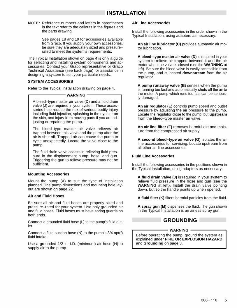
3. Unscrew the tie rod locknuts (102) from the tie rods(103). Remove the cotter pin (111). Unscrew the dis-placement rod (13) from the air motor (108). Careful-ly pull the displacement pump (101) off the air motor(108). Inspect the o–ring (110). See Fig 3.
4. Refer to page 10 for displacement pump service. Toservice the air motor, refer to the separate air motormanual (306–982 or 307–043), supplied.
RECONNECTING THE DISPLACEMENT PUMP
1. Lubricate the o–ring (110) and check that it is in placeon the displacement rod (13). Orient the pump’s fluidoutlet (R) to the air motor’s air inlet (S) as was notedin step 2 under Disconnecting the DisplacementPump. Position the displacement pump (101) on thetie rods (103). See Fig 3.
2. Screw the locknuts (102) onto the tie rods (103)loosely. Screw the displacement rod (13) into theshaft of the air motor (108) until the pin holes in therod and shaft align. Install the cotter pin (111).
3. Apply thread sealant to the pump fluid outlet (R) andthe threads of the fluid hose. Mount the pump and re-connect all hoses. Reconnect the ground wire if itwas disconnected during repair. Tighten the packingnut/wet–cup (2) so it is just snug – no tighter. Fill thewet–cup with Graco Throat Seal Liquid or compatiblesolvent.
4. Tighten the tie rod locknuts (102) evenly, and torqueas shown in Fig 3.
5. Start the pump and run it at about 40 psi (2.8 bar) airpressure, to check that it is operating properly.
6. Check for fluid leakage at the packing nut/wet–cup(2). Follow the Pressure Relief Procedure Warn-ing on page 8 before tightening the packing nut/wet–cup. Fig 3
103TORQUE TO
20–30 ft–lb(27–41 N.m)ON MODEL
224–342;10–15 ft–lb
(14–20 N.m)ON MODEL
224–343
110LUBRICATE
MODEL224–342SHOWN
����
108
111
101
102TORQUE TO
20–30 ft–lb(27–41 N.m)ON MODEL
224–342;10–15 ft–lb
(14–20 N.m)ON MODEL
224–343
13
2
RAPPLY SEALANT,AS REQUIRED
S
�� �������
SERVICE
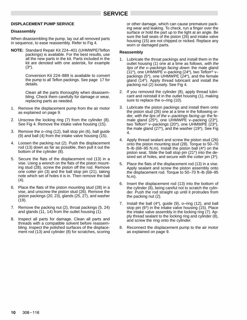
DISPLACEMENT PUMP SERVICE
Disassembly
When disassembling the pump, lay out all removed partsin sequence, to ease reassembly. Refer to Fig 4.
NOTE: Standard Repair Kit 224–401 (UHMWPE/Teflonpackings) is available. For the best results, useall the new parts in the kit. Parts included in thekit are denoted with one asterisk, for example(3*).
Conversion Kit 224–889 is available to convertthe pump to all Teflon packings. See page 17 fordetails.
Clean all the parts thoroughly when disassem-bling. Check them carefully for damage or wear,replacing parts as needed.
1. Remove the displacement pump from the air motoras explained on page 9.
2. Unscrew the locking ring (7) from the cylinder (8).See Fig 4. Remove the intake valve housing (15).
3. Remove the o–ring (12), ball stop pin (6), ball guide(9) and ball (4) from the intake valve housing (15).
4. Loosen the packing nut (2). Push the displacementrod (13) down as far as possible, then pull it out thebottom of the cylinder (8).
5. Secure the flats of the displacement rod (13) in avise. Using a wrench on the flats of the piston mount-ing stud (28), screw the piston off the rod. Removeone cotter pin (3) and the ball stop pin (21), takingnote which set of holes it is in. Then remove the ball(4).
6. Place the flats of the piston mounting stud (28) in avise, and unscrew the piston stud (26). Remove thepiston packings (20, 23), glands (25, 27), and washer(19).
7. Remove the packing nut (2), throat packings (5, 24)and glands (11, 14) from the outlet housing (1).
8. Inspect all parts for damage. Clean all parts andthreads with a compatible solvent before reassem-bling. Inspect the polished surfaces of the displace-ment rod (13) and cylinder (8) for scratches, scoring
or other damage, which can cause premature pack-ing wear and leaking. To check, run a finger over thesurface or hold the part up to the light at an angle. Besure the ball seats of the piston (26) and intake valvehousing (15) are not chipped or nicked. Replace anyworn or damaged parts.
Reassembly
1. Lubricate the throat packings and install them in theoutlet housing (1) one at a time as follows, with thelips of the v–packings facing down: the male gland(11*), one UHMWPE v–packing (24*), two Teflon� v–packings (5*), one UHMWPE (24*), and the femalegland (14*). Apply thread lubricant and install thepacking nut (2) loosely. See Fig 4.
2. If you removed the cylinder (8), apply thread lubri-cant and reinstall it in the outlet housing (1), makingsure to replace the o–ring (10).
3. Lubricate the piston packings and install them ontothe piston stud (26) one at a time in the following or-der, with the lips of the v–packings facing up: the fe-male gland (25*), one UHMWPE v–packing (23*),two Teflon� v–packings (20*), one UHMWPE (23*),the male gland (27*), and the washer (19*). See Fig4.
4. Apply thread sealant and screw the piston stud (26)onto the piston mounting stud (28). Torque to 50–70ft–lb (68–95 N.m). Install the piston ball (4*) on thepiston seat. Slide the ball stop pin (21*) into the de-sired set of holes, and secure with the cotter pin (3*).
5. Place the flats of the displacement rod (13) in a vise.Apply sealant and screw the piston assembly ontothe displacement rod. Torque to 50–70 ft–lb (68–95N.m).
6. Insert the displacement rod (13) into the bottom ofthe cylinder (8), being careful not to scratch the cylin-der. Push the rod straight up until it protrudes fromthe packing nut (2).
7. Install the ball (4*), guide (9), o–ring (12), and ballstop pin (6*) in the intake valve housing (15). Placethe intake valve assembly in the locking ring (7). Ap-ply thread sealant to the locking ring and cylinder (8),and screw the ring onto the cylinder.
8. Reconnect the displacement pump to the air motoras explained on page 9.

������� ��
Fig 4
�����
LIPS OF V–PACKINGSMUST FACE UP
28
26
*19
*27
*23
*20
*23
*25
*4
12
7APPLY SEALANT
15
9
8APPLY THREAD
LUBRICANT
21*
SEE DETAIL B
1
10
13
2APPLY THREADLUBRICANT
SEE DETAIL A
2
14*
24*
5*24*
11*LIPS OF
V–PACKINGSMUST FACE
DOWN
1
DETAIL A: THROA T PACKINGS
DETAIL B: PIST ON PACKINGS
6*
3*28
APPLY SEALANT ANDTORQUE TO 50–70 ft–lb
(68–95 N.m)
26APPLY SEALANT AND
TORQUE TO 50–70 ft–lb(68–95 N.m)

�� �������
NOTES:

������� ��
PARTS DRAWINGSAND
PARTS LISTS

�� �������
Model 224–342, Series A10:1 Ratio President � PumpIncludes items 101–111
PARTS DRAWING AND PARTS LIST
REF PARTNO. NO. DESCRIPTION QTY
101 224–341 DISPLACEMENT PUMP ASSYSee pages 16 and 17 for parts 1
102 102–021 NUT, lock; 3/8–16; stainless steel 3103 166–237 ROD, tie; stainless steel;
3.5” (89 mm) shoulder–to–shoulder 3108 207–352 AIR MOTOR
See 306–982 for parts 1110 156–082** SEAL, o–ring; nitrile rubber 1111 101–946** PIN, cotter; stainless steel;
0.12” (3.2 mm) x 1.5” (3.8 mm) 1
** Recommended “tool box” spare parts. Keep on hand to re-duce downtime.
306 numbers in descriptions refer to separate instruction manu-als, supplied.
HOW TO ORDER PARTS1 To be sure you receive the correct replacement parts, kits or
accessories, always give all of the information requested in thechart below.
2. Check the parts list to identify the correct part number; do not usethe ref. no. when ordering.
3. Order all parts from your nearest Graco distributor.
6 digitPart Number Qty Part Description
111**
108
101
102TORQUE TO 20–30 ft–lb(27–41 N.m)
����
103TORQUE TO 20–30 ft–lb(27–41 N.m)
110**LUBRICATE

������� ��
Model 224–343, Series A5:1 Ratio Monark � PumpIncludes items 101–111
PARTS DRAWING AND PARTS LIST
REF PARTNO. NO. DESCRIPTION QTY
101 224–341 DISPLACEMENT PUMP ASSYSee pages 16 and 17 for parts 1
102 102–021 NUT, lock; 3/8–16; stainless steel 3103 165–297 ROD, tie; stainless steel;
3.5” (89 mm) shoulder–to–shoulder 3108 205–997 AIR MOTOR
See 307–043 for parts 1110 156–082** SEAL, o–ring; nitrile rubber 1111 101–946** PIN, cotter; stainless steel;
0.12” (3.2 mm) x 1.5” (3.8 mm) 1
** Recommended “tool box” spare parts. Keep on hand to re-duce downtime.
306 and 307 numbers in descriptions refer to separate instruc-tion manuals, supplied.
HOW TO ORDER PARTS1 To be sure you receive the correct replacement parts, kits or
accessories, always give all of the information requested in thechart below.
2. Check the parts list to identify the correct part number; do not usethe ref. no. when ordering.
3. Order all parts from your nearest Graco distributor.
6 digitPart Number Qty Part Description111**
108
101
102TORQUE TO 10–15 ft–lb(14–20 N.m)
103TORQUE TO 10–15 ft–lb(14–20 N.m)
����
110**LUBRICATE

�� �������
Model 224–341, Series ASevere–Duty , Stainless Steel Displacement PumpIncludes items 1–28
PARTS DRAW-ING
1
2
*3
4*
*5
6*
7APPLY SEALANTTO THREADS
8
9
*11
12**
13
*14
15
19*
23*
23*
*21
20**24
*2425*
26APPLY SEALANTAND TORQUE TO50–70 ft–lb(68–95 N.m)
4*
27*
�����
**10
28APPLY SEALANTAND TORQUE TO
50–70 ft–lb(68–95 N.m)
LIPS OFV–PACKINGSMUST FACE DOWN
LIPS OFV–PACKINGS
MUST FACE UP

������� ��
PARTS LIST
Model 224–341, Series ASevere–Duty , Stainless Steel Displacement PumpIncludes items 1–28
REF PARTNO. NO. DESCRIPTION QTY
1 205–999 HOUSING, outlet; stainless steel 12 186–995 PACKING NUT/WET–CUP;
stainless steel 13 100–063* PIN, cotter; 1/16” x 1/2”; stainless steel 24 101–917* BALL; stainless steel;
0.875” (22 mm) dia. 25 162–866* V–PACKING, throat; Teflon� 26 162–947* PIN, ball stop, intake; stainless steel 17 164–630 RING, locking; stainless steel 18 186–994 CYLINDER; stainless steel 19 164–679 GUIDE, ball, intake; stainless steel 110 164–782** O–RING; Teflon� 111 186–987* GLAND, throat, male; stainless steel 112 164–846** O–RING; Teflon� 113 186–997 ROD, displacement; stainless steel 114 186–988* GLAND, throat, female; stainless steel 115 186–992 HOUSING, valve, intake;
stainless steel 119 176–634* WASHER, piston; stainless steel 120 176–635* V–PACKING, piston; Teflon� 221 176–637* PIN, ball stop, piston; stainless steel 123 176–638* V–PACKING, piston; UHMWPE 224 176–639* V–PACKING, throat; UHMWPE 225 186–989* GLAND, piston, female; stainless steel 126 186–993 STUD, piston; stainless steel 127 186–990* GLAND, piston, male; stainless steel 128 176–644 STUD, mounting, piston;
stainless steel 1
* The replacements for these parts are available in StandardRepair Kit 224–401 (UHMWPE/Teflon packings). Purchasethe kit separately.
** Recommended “tool box” spare parts. Keep on hand to re-duce downtime.
306 and 307 numbers in descriptions refer to separate instruc-tion manuals, supplied.
HOW TO ORDER PARTS1 To be sure you receive the correct replacement parts, kits or
accessories, always give all of the information requested in thechart below.
2. Check the parts list to identify the correct part number; do not usethe ref. no. when ordering.
3. Order all parts from your nearest Graco distributor.
6 digitPart Number Qty Part Description
OPTIONAL TEFLON� PACKING CONVERSIONKIT 224–889Use to convert the pump to all Teflon packings. Kit must be purchased separately. Kit includes:
PARTNO. DESCRIPTION QTY
162–866 V–PACKING; Teflon� 4186–987 GLAND, throat, male; stainless steel 1186–988 GLAND, throat, female; stainless steel 1176–635 V–PACKING, piston; Teflon� 4186–989 GLAND, piston, female; stainless steel 1186–990 GLAND, piston, male; stainless steel 1
�� �������
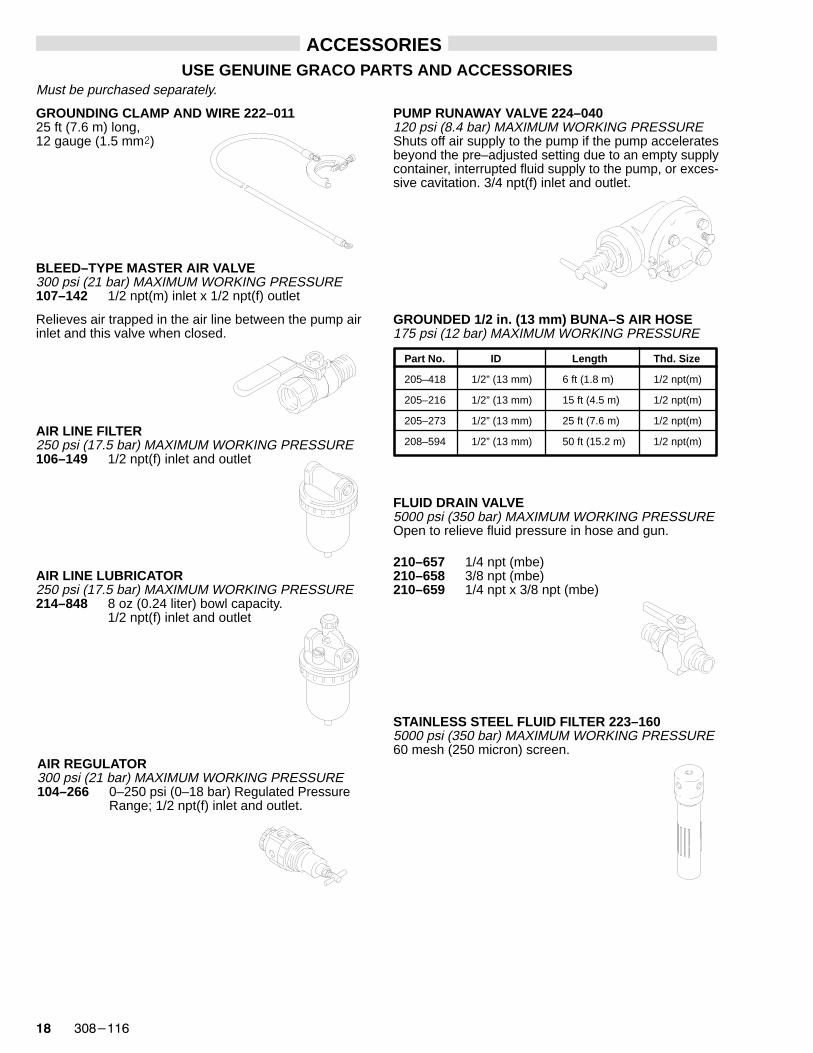
ACCESSORIESUSE GENUINE GRACO PARTS AND ACCESSORIES
Must be purchased separately.
GROUNDING CLAMP AND WIRE 222–01125 ft (7.6 m) long, 12 gauge (1.5 mm�)
BLEED–TYPE MASTER AIR V ALVE300 psi (21 bar) MAXIMUM WORKING PRESSURE107–142 1/2 npt(m) inlet x 1/2 npt(f) outlet
Relieves air trapped in the air line between the pump airinlet and this valve when closed.
AIR LINE FILTER250 psi (17.5 bar) MAXIMUM WORKING PRESSURE106–149 1/2 npt(f) inlet and outlet
AIR LINE LUBRICA TOR250 psi (17.5 bar) MAXIMUM WORKING PRESSURE214–848 8 oz (0.24 liter) bowl capacity.
1/2 npt(f) inlet and outlet
AIR REGULATOR300 psi (21 bar) MAXIMUM WORKING PRESSURE104–266 0–250 psi (0–18 bar) Regulated Pressure
Range; 1/2 npt(f) inlet and outlet.
PUMP RUNAWAY VALVE 224–040120 psi (8.4 bar) MAXIMUM WORKING PRESSUREShuts off air supply to the pump if the pump acceleratesbeyond the pre–adjusted setting due to an empty supplycontainer, interrupted fluid supply to the pump, or exces-sive cavitation. 3/4 npt(f) inlet and outlet.
GROUNDED 1/2 in. (13 mm) BUNA–S AIR HOSE175 psi (12 bar) MAXIMUM WORKING PRESSURE
Part No. ID Length Thd. Size
205–418 1/2” (13 mm) 6 ft (1.8 m) 1/2 npt(m)
205–216 1/2” (13 mm) 15 ft (4.5 m) 1/2 npt(m)
205–273 1/2” (13 mm) 25 ft (7.6 m) 1/2 npt(m)
208–594 1/2” (13 mm) 50 ft (15.2 m) 1/2 npt(m)
FLUID DRAIN VALVE5000 psi (350 bar) MAXIMUM WORKING PRESSUREOpen to relieve fluid pressure in hose and gun.
210–657 1/4 npt (mbe)210–658 3/8 npt (mbe)210–659 1/4 npt x 3/8 npt (mbe)
STAINLESS STEEL FLUID FIL TER 223–1605000 psi (350 bar) MAXIMUM WORKING PRESSURE60 mesh (250 micron) screen.
������� ��
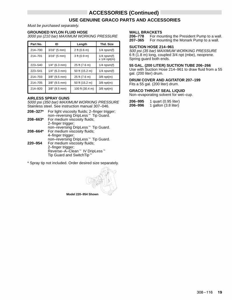
ACCESSORIES (Continued)USE GENUINE GRACO PARTS AND ACCESSORIES
Must be purchased separately.
Part No. ID Length Thd. Size
214–700 3/16” (5 mm) 2 ft (0.6 m) 1/4 npsm(f)
214–701 3/16” (5 mm) 3 ft (0.9 m) 1/4 npsm(f)x 1/4 npt(m)
223–540 1/4” (6.3 mm) 25 ft (7.6 m) 1/4 npsm(f)
223–541 1/4” (6.3 mm) 50 ft (15.2 m) 1/4 npsm(f)
214–703 3/8” (9.5 mm) 25 ft (7.6 m) 3/8 npt(m)
214–705 3/8” (9.5 mm) 50 ft (15.2 m) 3/8 npt(m)
214–920 3/8” (9.5 mm) 100 ft (30.4 m) 3/8 npt(m)
GROUNDED NYLON FLUID HOSE3000 psi (210 bar) MAXIMUM WORKING PRESSURE
AIRLESS SPRAY GUNS5000 psi (350 bar) MAXIMUM WORKING PRESSUREStainless steel. See instruction manual 307–046.208–327* For light viscosity fluids; 2–finger trigger;
non–reversing DripLess� Tip Guard.208–663* For medium viscosity fluids;
2–finger trigger;non–reversing DripLess� Tip Guard.
208–664* For medium viscosity fluids; 4–finger trigger;non–reversing DripLess� Tip Guard.
220–954 For medium viscosity fluids; 2–finger trigger;Reverse–A–Clean� IV DripLess�Tip Guard and SwitchTip�
* Spray tip not included. Order desired size separately.
Model 220–954 Shown
WALL BRACKETS206–778 For mounting the President Pump to a wall.207–365 For mounting the Monark Pump to a wall.
SUCTION HOSE 214–961500 psi (35 bar) MAXIMUM WORKING PRESSURE6 ft (1.8 m) long, coupled 3/4 npt (mbe), neoprene.Spring guard both ends.
55 GAL. (200 LITER) SUCTION TUBE 206–266Use with Suction Hose 214–961 to draw fluid from a 55gal. (200 liter) drum.
DRUM COVER AND AGITATOR 207–199Fits a 55 gal. (200 liter) drum.
GRACO THROAT SEAL LIQUIDNon–evaporating solvent for wet–cup.
206–995 1 quart (0.95 liter)206–996 1 gallon (3.8 liter)
�� �������
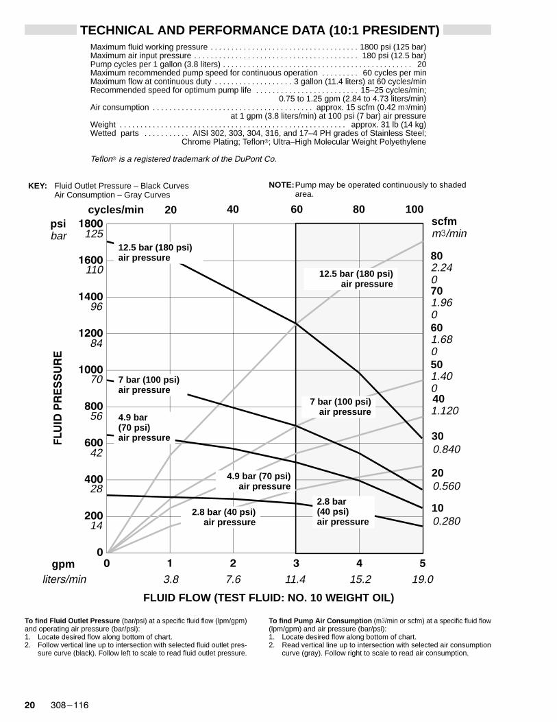
TECHNICAL AND PERFORMANCE DATA (10:1 PRESIDENT)Maximum fluid working pressure 1800 psi (125 bar). . . . . . . . . . . . . . . . . . . . . . . . . . . . . . . . . . . . Maximum air input pressure 180 psi (12.5 bar). . . . . . . . . . . . . . . . . . . . . . . . . . . . . . . . . . . . . . . . Pump cycles per 1 gallon (3.8 liters) 20. . . . . . . . . . . . . . . . . . . . . . . . . . . . . . . . . . . . . . . . . . . . . . Maximum recommended pump speed for continuous operation 60 cycles per min. . . . . . . . . Maximum flow at continuous duty 3 gallon (11.4 liters) at 60 cycles/min. . . . . . . . . . . . . . . . . . . Recommended speed for optimum pump life 15–25 cycles/min;. . . . . . . . . . . . . . . . . . . . . . . . .
0.75 to 1.25 gpm (2.84 to 4.73 liters/min)Air consumption approx. 15 scfm (0.42 m�/min). . . . . . . . . . . . . . . . . . . . . . . . . . . . . . . . . . . . . . .
at 1 gpm (3.8 liters/min) at 100 psi (7 bar) air pressureWeight approx. 31 lb (14 kg). . . . . . . . . . . . . . . . . . . . . . . . . . . . . . . . . . . . . . . . . . . . . . . . . . . . . . . Wetted parts AISI 302, 303, 304, 316, and 17–4 PH grades of Stainless Steel;. . . . . . . . . . .
Chrome Plating; Teflon�; Ultra–High Molecular Weight Polyethylene
Teflon� is a registered trademark of the DuPont Co.
�
���
���
���
���
����
����
����
����
����
� � � � � �
liters/min 3.8 7.6 11.4 15.2 19.0
FLUID FLOW (TEST FLUID: NO. 10 WEIGHT OIL)
gpm
To find Fluid Outlet Pressure (bar/psi) at a specific fluid flow (lpm/gpm)and operating air pressure (bar/psi):1. Locate desired flow along bottom of chart.2. Follow vertical line up to intersection with selected fluid outlet pres-
sure curve (black). Follow left to scale to read fluid outlet pressure.
To find Pump Air Consumption (m�/min or scfm) at a specific fluid flow(lpm/gpm) and air pressure (bar/psi):1. Locate desired flow along bottom of chart.2. Read vertical line up to intersection with selected air consumption
curve (gray). Follow right to scale to read air consumption.
14
cycles/min 20 80scfmm�/min
psibar
7 bar (100 psi)air pressure
4.9 bar(70 psi)air pressure
7 bar (100 psi)air pressure
4.9 bar (70 psi)air pressure
KEY: Fluid Outlet Pressure – Black CurvesAir Consumption – Gray Curves
NOTE: Pump may be operated continuously to shadedarea.
40
28
42
56
84
70
96
60
200.560
401.120
110
601.680
12.5 bar (180 psi)air pressure
12.5 bar (180 psi)air pressure
2.8 bar (40 psi)air pressure
2.8 bar(40 psi)air pressure
802.240
125
100.280
300.840
501.400
701.960
100
������� ��
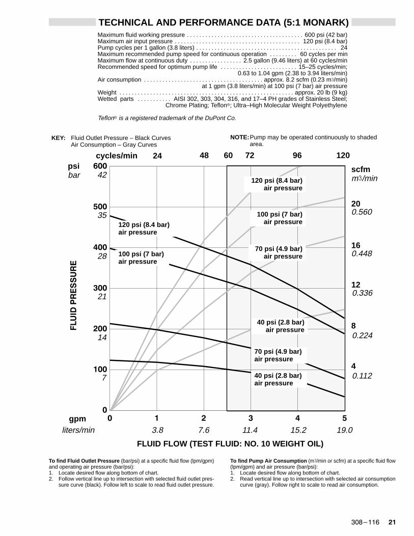
TECHNICAL AND PERFORMANCE DATA (5:1 MONARK)Maximum fluid working pressure 600 psi (42 bar). . . . . . . . . . . . . . . . . . . . . . . . . . . . . . . . . . . . . . Maximum air input pressure 120 psi (8.4 bar). . . . . . . . . . . . . . . . . . . . . . . . . . . . . . . . . . . . . . . . . Pump cycles per 1 gallon (3.8 liters) 24. . . . . . . . . . . . . . . . . . . . . . . . . . . . . . . . . . . . . . . . . . . . . . Maximum recommended pump speed for continuous operation 60 cycles per min. . . . . . . . . Maximum flow at continuous duty 2.5 gallon (9.46 liters) at 60 cycles/min. . . . . . . . . . . . . . . . . Recommended speed for optimum pump life 15–25 cycles/min;. . . . . . . . . . . . . . . . . . . . . . . . .
0.63 to 1.04 gpm (2.38 to 3.94 liters/min)Air consumption approx. 8.2 scfm (0.23 m�/min). . . . . . . . . . . . . . . . . . . . . . . . . . . . . . . . . . . . . . .
at 1 gpm (3.8 liters/min) at 100 psi (7 bar) air pressureWeight approx. 20 lb (9 kg). . . . . . . . . . . . . . . . . . . . . . . . . . . . . . . . . . . . . . . . . . . . . . . . . . . . . . . . . Wetted parts AISI 302, 303, 304, 316, and 17–4 PH grades of Stainless Steel;. . . . . . . . . . .
Chrome Plating; Teflon�; Ultra–High Molecular Weight Polyethylene
Teflon� is a registered trademark of the DuPont Co.
�
���
���
���
���
���
���
� � � � � �
FLUID FLOW (TEST FLUID: NO. 10 WEIGHT OIL)
gpmliters/min
To find Fluid Outlet Pressure (bar/psi) at a specific fluid flow (lpm/gpm)and operating air pressure (bar/psi):1. Locate desired flow along bottom of chart.2. Follow vertical line up to intersection with selected fluid outlet pres-
sure curve (black). Follow left to scale to read fluid outlet pressure.
To find Pump Air Consumption (m�/min or scfm) at a specific fluid flow(lpm/gpm) and air pressure (bar/psi):1. Locate desired flow along bottom of chart.2. Read vertical line up to intersection with selected air consumption
curve (gray). Follow right to scale to read air consumption.
3.8
cycles/min 24 120
40.112
psibar
100 psi (7 bar)air pressure
70 psi (4.9 bar)air pressure
100 psi (7 bar)air pressure
70 psi (4.9 bar)air pressure
KEY: Fluid Outlet Pressure – Black CurvesAir Consumption – Gray Curves
NOTE: Pump may be operated continuously to shadedarea.
48
14
21
42
7.6
96
80.224
120.336
120 psi (8.4 bar)air pressure
120 psi (8.4 bar)air pressure
40 psi (2.8 bar)air pressure
40 psi (2.8 bar)air pressure
7
35200.560
scfmm�/min
72
28160.448
11.4 15.2 19.0
60

�� �������
DIMENSIONAL DRAWING
Model 224–342 Shown
A
C
Pump A B CModel
224–342 28.38 in. 14.63 in. 13.75 in.(721 mm) (372 mm) (349 mm)
224–343 25.25 in. 11.5 in. 13.75 in.(641 mm) (292 mm) (349 mm)
1/2 npt(f)AIR INLET
1/2 npt(f)FLUID OUTLET
MOUNTING HOLE LAYOUT
0.28” (7.1 mm) DIA.
5.0”(127 mm)
2.5”(64 mm)
4.38”(111.3 mm)
DIA.
3/4 npt(f)FLUID INTAKE
B
USE GASKET 166–392(ORDER SEPARATELY)
���
����

������� ��
NOTES:

�� �������
THE GRACO WARRANTY AND DISCLAIMERSWARRANTY
Graco warrants all equipment manufactured by it and bearing its name to be free from defects in material and workman-ship on the date of sale by an authorized Graco distributor to the original purchaser for use. As purchaser’s sole remedyfor breach of this warranty, Graco will, for a period of twelve months from the date of sale, repair or replace any part of theequipment proven defective. This warranty applies only when the equipment is installed, operated and maintained inaccordance with Graco’s written recommendations.
This warranty does not cover, and Graco shall not be liable for, any malfunction, damage or wear caused by faulty instal-lation, misapplication, abrasion, corrosion, inadequate or improper maintenance, negligence, accident, tampering, orsubstitution of non–Graco component parts. Nor shall Graco be liable for malfunction, damage or wear caused by theincompatibility with Graco equipment of structures, accessories, equipment or materials not supplied by Graco, or theimproper design, manufacture, installation, operation or maintenance of structures, accessories, equipment or materi-als not supplied by Graco.
This warranty is conditioned upon the prepaid return of the equipment claimed to be defective to an authorized Gracodistributor for verification of the claim. If the claimed defect is verified, Graco will repair or replace free of charge anydefective parts. The equipment will be returned to the original purchaser transportation prepaid. If inspection of theequipment does not disclose any defect in material or workmanship, repairs will be made at a reasonable charge, whichcharges may include the costs of parts, labor and transportation.
DISCLAIMERS AND LIMIT ATIONS
THE TERMS OF THIS WARRANTY CONSTITUTE PURCHASER’S SOLE AND EXCLUSIVE REMEDY AND ARE IN LIEU OF ANY OTHER WAR-RANTIES (EXPRESS OR IMPLIED), INCLUDING WARRANTY OF MERCHANTABILITY OR WARRANTY OF FITNESS FOR A PARTICULAR PUR-POSE, AND OF ANY NON–CONTRACTUAL LIABILITIES, INCLUDING PRODUCT LIABILITIES, BASED ON NEGLIGENCE OR STRICT LIABILITY.EVERY FORM OF LIABILITY FOR DIRECT, SPECIAL OR CONSEQUENTIAL DAMAGES OR LOSS IS EXPRESSLY EXCLUDED AND DENIED. INNO CASE SHALL GRACO’S LIABILITY EXCEED THE AMOUNT OF THE PURCHASE PRICE. ANY ACTION FOR BREACH OF WARRANTY MUSTBE BROUGHT WITHIN TWO (2) YEARS OF THE DATE OF SALE.
EQUIPMENT NOT COVERED BY GRACO WARRANTY
GRACO MAKES NO WARRANTY, AND DISCLAIMS ALL IMPLIED WARRANTIES OF MERCHANTABILITY AND FITNESS FOR A PARTICULARPURPOSE, WITH RESPECT TO ACCESSORIES, EQUIPMENT, MATERIALS, OR COMPONENTS SOLD BUT NOT MANUFACTURED BY GRACO.These items sold, but not manufactured by Graco (such as electric motor, switches, hose, etc.) are subject to the war-ranty, if any, of their manufacturer. Graco will provide purchaser with reasonable assistance in making any claim forbreach of these warranties.
IMPORTANT PHONE NUMBERSTO PLACE AN ORDER , contact your Graco distributor,or call this number to identify the distributor closest toyou: 1–800–328–0211 Toll Free
FOR TECHNICAL ASSISTANCE , service repair infor-mation or assistance regarding the application of Gracoequipment: 1–800–543–0339 Toll Free
Factory Branches: Atlanta, Chicago, Dallas, Detroit, Los Angeles, Mt. Arlington (N.J.)Subsidiary and Affiliate Companies: Canada; England; Switzerland; France; Germany; Hong Kong; Japan; Korea
GRACO INC. P.O. BOX 1441 MINNEAPOLIS, MN 55440–1441PRINTED IN U.S.A. 308–116 9–91 Revised 10–92