Seven Phase Brush-less Synchronous Motor with …ieee.rackoneup.net/rrvs/08/Seven Phase Brushless...
7
Abstract This paper illustrates a unique inverted DC Brush less motor configuration intended for propulsion and transportation systems. This paper discusses the design factors influencing the inverter architecture. The paper discusses the magnetic design along with the motor characteristics, which are utilized further for the design of the electronics. First three sections discuss the motor magnetic design. Section four discusses the inverter design. The paper concludes with possible improvement options for the inverter. Keywords: Brush-less, Half-bridge, Full-Bridge, Inverter, permanent magnet 1. Introduction Multi-phase permanent magnet motors have been around for many years. A recent development unveils a seven-phase permanent magnet motor with magnetically isolated stator windings. This motor is fabricated with surface magnets on the outer rotor ring and internal stator windings. The motor has eight magnet pole pairs and seven stator pole pairs. Each stator winding is phase shifted from its neighboring winding by a predetermined margin. These windings are configured so as to minimize any mutual inductance between the various windings. The configuration of the windings can be such as to allow for a star, a delta or a combination arrangement. An inverter has been developed for this particular motor with seven individual windings in a star configuration. This inverter consists of seven half bridges in parallel. Inverter is modulated with a Sinusoidal PWM. The motor is torque- controlled with seven equal and phase shifted sinusoidal currents. This motor’s unique winding arrangement and properties allow for a reduction in overall size of electronics. The paper discusses the inverter design and optimization of electronic components because of this motor’s unique properties. One of the obvious advantages is to be able to use low cost MOSFETs as the current in each winding reduces owing to larger number of phases compared to traditional three phase motors. Also, another advantage is the reduction in power source ripple current as the phases are increased in a non-duplicate or non-overlapping fashion. Such an inverter has been built and experimental results are presented and analyzed with respect to theoretical predictions and circuit simulations. This motor allows for unique flexibility in being able to increase or decrease the stator phases without major redesign. This can be a substantial advantage from several points of view. One being the fact the proper optimizations of electronics can be performed with a requested change in the number of phases. Another being the fact that motor performance and characteristics can be matched as per customer requirements with the ability to change the number of stator phases without major redesign. These and several other advantages are discussed in the paper. Delta configuration for such a multi-phase motor is also discussed. A combination arrangement with a star-delta arrangement is also discussed briefly in this paper. Those results are analyzed and compared. 2. New Seven Phase Brush-less Synchronous Motor Fig. 1: Basic Motor Architecture Adaptive motors developed by Wavecrest Laboratories are a class of brush-less synchronous motors designed for future transportation and propulsion systems [1]. These motors have a unique stator configuration. The isolated stators are completely independent of each other’s magnetic field and consequently yield a high degree of performance and flexibility in the design of inverters. The basic motor structure is shown in Figure: 1. The basic motor structure consists of surface magnet rotor and 7-coil stator. As can be seen from Figure 1, the 7-coil arrangement is independent with no mutual coupling between the coils. This kind of arrangement lends itself for system level optimization as is demonstrated in this paper. Depending on the maximum deliverable torque and permissible maximum angular velocity of the application along with the available DC bus voltage, the electromagnetic designs of the motor can be reconfigured to increase the peak and continuous power outputs, as well as the intrinsic no-load speed of the machine for a given compact design. Such design considerations tend to have an Seven Phase Brush-less Synchronous Motor with Reduced Inverter Size Rakesh Dhawan , Zareh Soghomonian Wavecrest Laboratories 45600 Terminal Drive, Dulles, VA 20166 0-7803-8269-2/04/$17.00 (C) 2004 IEEE. 1099
Transcript of Seven Phase Brush-less Synchronous Motor with …ieee.rackoneup.net/rrvs/08/Seven Phase Brushless...

Abstract This paper illustrates a unique inverted DC Brush less motor configuration intended for propulsion and transportation systems. This paper discusses the design factors influencing the inverter architecture. The paper discusses the magnetic design along with the motor characteristics, which are utilized further for the design of the electronics. First three sections discuss the motor magnetic design. Section four discusses the inverter design. The paper concludes with possible improvement options for the inverter. Keywords: Brush-less, Half-bridge, Full-Bridge, Inverter, permanent magnet 1. Introduction Multi-phase permanent magnet motors have been around for many years. A recent development unveils a seven-phase permanent magnet motor with magnetically isolated stator windings. This motor is fabricated with surface magnets on the outer rotor ring and internal stator windings. The motor has eight magnet pole pairs and seven stator pole pairs. Each stator winding is phase shifted from its neighboring winding by a predetermined margin. These windings are configured so as to minimize any mutual inductance between the various windings. The configuration of the windings can be such as to allow for a star, a delta or a combination arrangement. An inverter has been developed for this particular motor with seven individual windings in a star configuration. This inverter consists of seven half bridges in parallel. Inverter is modulated with a Sinusoidal PWM. The motor is torque-controlled with seven equal and phase shifted sinusoidal currents. This motor’s unique winding arrangement and properties allow for a reduction in overall size of electronics. The paper discusses the inverter design and optimization of electronic components because of this motor’s unique properties. One of the obvious advantages is to be able to use low cost MOSFETs as the current in each winding reduces owing to larger number of phases compared to traditional three phase motors. Also, another advantage is the reduction in power source ripple current as the phases are increased in a non-duplicate or non-overlapping fashion. Such an inverter has been built and experimental results are presented and analyzed with respect to theoretical predictions and circuit simulations.
This motor allows for unique flexibility in being able to increase or decrease the stator phases without major redesign. This can be a substantial advantage from several points of view. One being the fact the proper optimizations of electronics can be performed with a requested change in the number of phases. Another being the fact that motor performance and characteristics can be matched as per customer requirements with the ability to change the number of stator phases without major redesign. These and several other advantages are discussed in the paper. Delta configuration for such a multi-phase motor is also discussed. A combination arrangement with a star-delta arrangement is also discussed briefly in this paper. Those results are analyzed and compared. 2. New Seven Phase Brush-less Synchronous Motor
Fig. 1: Basic Motor Architecture
Adaptive motors developed by Wavecrest Laboratories are a class of brush-less synchronous motors designed for future transportation and propulsion systems [1]. These motors have a unique stator configuration. The isolated stators are completely independent of each other’s magnetic field and consequently yield a high degree of performance and flexibility in the design of inverters.
The basic motor structure is shown in Figure: 1. The basic motor structure consists of surface magnet rotor and 7-coil stator. As can be seen from Figure 1, the 7-coil arrangement is independent with no mutual coupling between the coils. This kind of arrangement lends itself for system level optimization as is demonstrated in this paper. Depending on the maximum deliverable torque and permissible maximum angular velocity of the application along with the available DC bus voltage, the electromagnetic designs of the motor can be reconfigured to increase the peak and continuous power outputs, as well as the intrinsic no-load speed of the machine for a given compact design. Such design considerations tend to have an
Seven Phase Brush-less Synchronous Motor with Reduced Inverter Size
Rakesh Dhawan , Zareh Soghomonian Wavecrest Laboratories
45600 Terminal Drive, Dulles, VA 20166
0-7803-8269-2/04/$17.00 (C) 2004 IEEE. 1099
effect on the internal and external infrastructure of the stator, as careful design synthesis has to be carried out to find out the most optimum synergy between the Machine, Torque and Back emf constants, otherwise referred to as Km, Kt and Ke, respectively. In contrast with the continuing emergence of low loss non-oriented electrical steels, greater emphasis was directed the modularization of the motor design and an increase in the power and torque density of the motor. The designs considered for this paper were predominantly based on 36V DC bus supply voltage with a peak current ranging from 50 to 200 Amps. To ensure that the desired motor characteristics were realized, a greater emphasis was put on the design and AC excitation measurements of the electromagnets used in the motor as well. 2.1 The Design Considerations for the Motor For the purpose of this paper, a new radial machine topology was considered. The stator sub-system consisted of the plurality of independent electromagnet constituents, which omits the mutual inductances normally seen in a multi-phase machine design. Due to the complexity of the three-dimensional (3D) topologies of the electromagnetic cores used in these machines, the required electromagnetic cores were manufactured from two commercial Soft Magnetic Composite (SMC) powder alloys as opposed to laminated electrical steels. The main machine parameters are listed in Table 1. With the use of SMC materials all the stringent geometrical constraints and the required electromagnetic characteristics were met for the designated electrical power requirements. Moreover, SMC alloys promoted the realization of a specific acceptable power loss (W/kg) and relative permeability at the application flux density levels and excitation frequencies. This allowed the desired peak torque output to be achieved with a significant reduction in material weight and manufacturing overheads. Due to the isotropic nature of the SMC materials, the construction magnetic paths were fully optimized in 3D with respect to the volumetric and physical constants of each machine specification. For the purpose of this study 3D Finite Element analysis was carried out using Ansoft Maxwell 3D Finite Element Analysis (FEA) software to optimize the electromagnetic path of the machine. The resultant motor achieved high stall-torque and high-continuous torque across a wide range of angular speeds. It also exhibited good average efficiency at different torque/speed ranges. 2.2 The Rotor design The motor highlighted in this paper, the rotor comprised of a plurality of magnet segments held in position with a soft magnetic back iron ring made of solid mild steel. The back iron is further integrated into a rotor housing, which is attached to the pivoting shaft of the inverted machine. The magnet segments were shaped in rounded sectors with
square cross-sections and tapered edges to minimize cross interference of unwanted magnetic flux. Table: 1: Motor Design Parameters
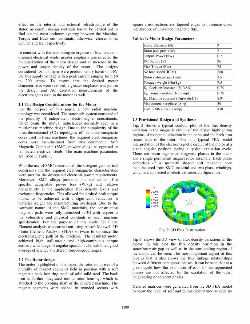
2.3 Provisional Design and Synthesis Fig: 2 shows a typical contour plot of the flux density variation in the magnetic circuit of the design highlighting regions of moderate induction in the cores and the back iron return path of the rotor. This is a typical FEA model interpretation of the electromagnetic circuit of the motor at a given angular position during a typical excitation cycle. There are seven segmented magnetic phases in the stator and a single permanent magnet rotor assembly. Each phase comprises of a specially shaped soft magnetic core manufactured from SMC material and two phase windings, which are connected in electrical series configuration.
Fig. 2: 3D Flux Distribution
Fig 3: shows the 3D view of flux density variations in the motor. In this plot the flux density variation in the stator/rotor air gap as well as in the surrounding region of the motor can be seen. The most important aspect of this plot is that it also shows the flux linkage relationships between different contiguous phases. It can be seen that at a given cycle how the excitation of each of the segmented phases are not affected by the excitation of the other neighboring or adjacent phases. Detailed matrices were generated from the 3D FEA model to show the level of self and mutual inductance as seen by
Stator Elements (Ns) 7 Rotor pole pairs (Nr) 8 Output Power (kW) 0.7 DC Supply (V) 36 Max Torque (Nm) 75 No load speed (RPM) 260 Rotor stator air gap (mm) 1.5 Torque / weight (Nm/kg) 7.5 Ke, Back emf constant (V/RAD) 0.75 Kt, Torque constant (Nm / mp) 0.75 Km Machine constant (Nm/watts1/2) 1.91 Max current per phase (Amp) 30 Total RMS current (Amp) 150
1100
each phase, as well as the flux-coupling coefficient normalized with respect to each phase. These coupling coefficient and inductance matrices show how that the lack of mutual inductance between the phases could offer addition degree of freedom in the excitation control of the motor, which could not be realized in conventional motor design.
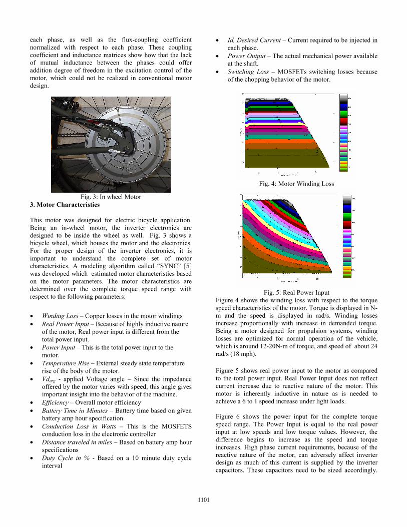
Fig. 3: In wheel Motor
3. Motor Characteristics
This motor was designed for electric bicycle application. Being an in-wheel motor, the inverter electronics are designed to be inside the wheel as well. Fig. 3 shows a bicycle wheel, which houses the motor and the electronics. For the proper design of the inverter electronics, it is important to understand the complete set of motor characteristics. A modeling algorithm called “SYNC” [5] was developed which estimated motor characteristics based on the motor parameters. The motor characteristics are determined over the complete torque speed range with respect to the following parameters: • Winding Loss – Copper losses in the motor windings • Real Power Input – Because of highly inductive nature
of the motor, Real power input is different from the total power input.
• Power Input – This is the total power input to the motor.
• Temperature Rise – External steady state temperature rise of the body of the motor.
• Vdarg - applied Voltage angle – Since the impedance offered by the motor varies with speed, this angle gives important insight into the behavior of the machine.
• Efficiency – Overall motor efficiency • Battery Time in Minutes – Battery time based on given
battery amp hour specification. • Conduction Loss in Watts – This is the MOSFETS
conduction loss in the electronic controller • Distance traveled in miles – Based on battery amp hour
specifications • Duty Cycle in % - Based on a 10 minute duty cycle
interval
• Id, Desired Current – Current required to be injected in each phase.
• Power Output – The actual mechanical power available at the shaft.
• Switching Loss – MOSFETs switching losses because of the chopping behavior of the motor.
Fig. 4: Motor Winding Loss
Fig. 5: Real Power Input
Figure 4 shows the winding loss with respect to the torque speed characteristics of the motor. Torque is displayed in N-m and the speed is displayed in rad/s. Winding losses increase proportionally with increase in demanded torque. Being a motor designed for propulsion systems, winding losses are optimized for normal operation of the vehicle, which is around 12-20N-m of torque, and speed of about 24 rad/s (18 mph). Figure 5 shows real power input to the motor as compared to the total power input. Real Power Input does not reflect current increase due to reactive nature of the motor. This motor is inherently inductive in nature as is needed to achieve a 6 to 1 speed increase under light loads. Figure 6 shows the power input for the complete torque speed range. The Power Input is equal to the real power input at low speeds and low torque values. However, the difference begins to increase as the speed and torque increases. High phase current requirements, because of the reactive nature of the motor, can adversely affect inverter design as much of this current is supplied by the inverter capacitors. These capacitors need to be sized accordingly.
1101

However, another factor, which affects the capacitors, is the amount of time under which they need to supply that current. For this application, that time tends to be relatively small.
Fig. 6: Power Input
Fig. 7: Applied Voltage Angle
Figure 7 shows in degrees, angle of the applied voltage. This is another way to evaluate how inductive a motor is. Cosine of this angle will result in the power factor of this motor. In the control strategy for the inverter drive, the applied phase current is always in phase with the back emf voltage of the motor to obtain most efficient power output. However, it is shown later in this paper that the maximum output power can be obtained for every value of speed and current by varying the phase angle of the applied phase current with respect to its back emf voltage. Figure 8 shows power output of the motor in Watts. It is important to note that the motor is capable of delivering a peak power of close to 1500W, however, for the most of the time, end application only requires a continuous draw of 250 to 350 Watts. This illustrates one of the basic nature of the gearless, brush-less propulsion systems. The ratio of peak power to continuous power can be as high as 6 in certain applications. The inverter electronics need to be designed for both the power levels. An important point at this juncture is the fact that having electronics inside the motor (as is the case in this application), encourages an integral design of the inverter with respect to the motor and avoids oversize of the inverter. Also, we should bear in mind the fact that the motor thermal time constant is a magnitude larger than the inverter
electronics thermal time constant. And peak torque demands are a magnitude smaller than the motor thermal time constant. Therefore, with any combination of regular and peak power demands, there does not occur an event, which can adversely affect the operation of electronics inside the motor. Consequently, a clever system integration of the inverter with the motor can result in less expensive, more reliable and compact electronics. Manufacturing of such a system is challenging but feasible.
Fig. 8: Output Power
Fig. 9: Current Required per Phase (Amps)
Figure 9 shows current required per phase for this motor. As can be seen, torque produced is directly proportional to the current per phase. This figure illustrates the fact that the current per phase than the actual power output affects inverter electronics more. This is so because the power output increases linearly with speed as torque is kept constant. The losses in the inverter virtually remain steady and are mainly current dependent. Therefore, a due attention should be paid to the inverter electronics with respect to its current handling ability. Figure 10 shows the winding losses in Watts. Winding losses during normal mode of operation are fairly negligible. However, they increase rapidly as the power output increases. This illustrates another characteristic of this motor. Motors designed for propulsion systems tend to be very inefficient under heavy torque demands. This is not a drawback as efficiency is not important under those short bursts of high torque demand and it also helps to keep the motor and inverter electronics small.
1102

Fig. 10: Winding Losses (Watts)
Fig. 11 MOSFET Conduction Losses
Fig. 12: Switching Losses in MOSFETs
Figure 11 illustrates conduction losses in 14 MOSFETs used in the inverter electronics (Half-Bridge architecture with 7-phase star configuration). This motor and inverter electronics operate from a 36V battery source. This voltage level has allowed for many inexpensive and efficient MOSFETs to be available. Even under heavy torque demands, conduction losses compared to the output power remain very low. Figure 12 shows the switching losses in 14 MOSFETs used in the inverter electronics. Because of the nature of the low voltage MOSFETs and their fast switching speed, the switching losses are extremely low at all output power levels. Also, the switching frequency of the inverter is merely 16 kHz. Therefore, the inverter electronics add insignificant amount of losses to the overall system. This is a marked difference as compared to high voltage inverter electronics. High voltage inverter electronics tend to be less efficient and more expensive and moreover, with high voltage electronics, one has to deal with additional design
constraints such as shock and fire safety of the end user. Such issues are virtually non-existent in low voltage systems.
Fig. 13: Overall System Efficiency
Figure 13 shows the overall system efficiency at various power levels. Back iron and core losses are assumed negligible as is the case with the brush-less synchronous motors. As can be seen, efficiency under peak torque demand can fall to very low values. However, under regular operation, efficiency is maintained well into 90%. This is a fairly standard characteristic for a well-designed propulsion system.
Fig. 14: System Duty Cycle
Duty cycle is defined as amount of time the system needs to be on in a 10-minute interval. This motor is designed to
operate under limited duty cycle so as to optimize the size and performance of this system under various operating points. It is important to make sure that under normal mode of operation, the end user does not hit the duty cycle limit. Under peak torque operation, the user only requires a duty cycle of less than 1% whereas motor is designed to have a duty cycle of 6-8%. However, the system is supposed to deliver continuous (100% duty cycle) torque of 20 N-m under all speed values. Figure 15 illustrates two things. One is the extended speed range of the motor due to phase advance and secondly battery amperes required at various torque levels multiplied by 10. For most of the operation, the system delivers 1 Nm/Amp except at low speeds where it may deliver up to 6 Nm/Amp.
1103

Fig. 15: Phase Advance/Field Weakening
P
Input PowerConditioning
Input PowerConditioning
VoltageTransformationand Distribution
Testing Interface ControllerInterface
ParameterSensing andMonitoring
Real TimeProtection
Gate DriveCircuits
PowerProcessing
Circuit
Voltage andCurrent
Snubbers
Transducers
Power SourceInterface
Main Processor
ProgrammingInterface
SignalConditioning
UserInterface
CommunicationProtocols
Power AmplifierInterface
Analog Input(s)InterfaceAnalog
Output(s)Interface
Digital Input(s)Interface
Digital Output (s)Interface
Position SensorInterface
StaticRAM
RotationalPositional
Transducers
Power Source Power SourceProtection
Power SourceConditioning
Battery Interface
M
DSP Controller
Battery
PowerElectronics
SignalConditioning
PositionSensor
Fig. 16: System Architecture
4. System Design Figure 15 shows the overall system level block diagram. There are four main functional modules, which make the inverter electronics – Battery, Controller, Position Sensor and Power Electronics. All of these modules are discussed below: Battery: This consists of the actual battery (which may be of any chemistry type such as NimH, Lead Acid or Li ion etc) along with associated battery management system, battery protection circuitry and power source conditioning circuitry. Battery feeds directly into the Power Electronics. Controller: The controller module may consists of many available schemes such as analog ICs to 8-bit micro-controllers to 16-bit fixed point DSP controller. Much of the controller design is driven by user requirements, cost and performance. This module interfaces with the user and therefore may require signal-conditioning circuit for each of the inputs and outputs, which interface with the outside world. It may also require analog and digital interface to these inputs/outputs depending upon the controller architecture. If the module is DSP or micro-controller based architecture, it may be required to interface via serial link or CAN communication protocol, which would require additional circuitry. This module needs to interface with the position sensors so as to drive the power electronics correctly. This module may also be required to interface with the battery module. A separate power source such as +3.3V or 5V is normally required to power the controller.
Cost of such a power source should be considered in the design as well. Position Sensors: Position sensors are required in most of the permanent magnet machines so as to correctly energize the phases to get efficient power transfer. One of the most popular schemes is the utilization of hall sensors to estimate relative position. Hall sensors when properly located can be used to provide reliable position information. Some of the other schemes use optical or capacitive techniques, which can work equally well. All of these techniques require some form of signal conditioning while interfacing with the controller. Power Electronics: This module mainly consists of analog and switching components such as MOSFETs, MOSFET gate drivers, current and voltage sensors, current and voltage snubbers and auxiliary protection circuitry. One of the major advantages of the 7-phase motor is the fact that the current is reduced substantially in the motor windings. This benefits the inverter size two ways – first, it allows us to use inexpensive MOSFETs and secondly, it substantially reduces the high frequency ripple current in the bus capacitors. Bus capacitors are a major contributor to the overall volume of these drives. Therefore 7-phase motor topology results in substantial increase in the overall efficiency and substantial decrease in the overall size of the inverter electronics as compared to 3-phase inverter drives. In order to process power, MOSFETs can be arranged in two architectures – Half-Bridge and Full-Bridge. Both circuits work equally well and have about the same performance characteristics with Half-Bridge having some additional advantages. However, motor design is required to be changed when changing architectures so as to maintain the same torque-speed performance. An example is shown in Table 2. Table 2: Half-Bridge vs. Full Bridge System Architecture Motor Parameters Original Half-Bridge Full-Bridge Resistance per Phase Rw Rw 4*Rw Inductance per phase Lw Lw 4*Lw Torque Constant Kt Kt 2*Kt Current per phase Id Id Id/2 Winding loss per phase Id
2Rw Id2Rw Id
2Rw MOSFET Conduction losses Closs Closs/2 MOSFET Switching Losses Sloss 0.75*Sloss Battery Voltage - Vdc Vdc Available Voltage per phase - Vdc/2 Vdc Number of MOSFETs per phase
- 2 4
Number of Turns N N 2*N Wire Diameter d d d/2 Backemf Voltage e e 2*e Battery Current - Idc Idc Automatic MOSFET failure indication
Yes No
Automatic Phase failure Indication
Yes No
Automatic Single Point System health indicator
Yes No
Cost C 2*C
1104
As can be seen in the table above, full-bridge inverter at low battery voltage tends to be more efficient than the half-bridge inverters. However, because the conduction and switching losses are so negligible that they do not increase the efficiency substantially. Half-bridge offers substantial advantages such as lower cost, better layout efficiency, better system performance and substantial improvement in fault diagnosis. This is so because of the existence of the neutral point in the half-bridge architecture. Under well-balanced load conditions, the neutral is exactly one-half the battery voltage. Fault detection is improved substantially with the presence of the neutral point. The neutral either goes to rail or ground under FET failure. The neutral also goes to a value other than the bus voltage or ground or one-half of the bus voltage when one or many phases stop functioning. This would result in neutral current if neutral was connected back to the power source. Therefore, the neutral point always indicates system health under all operating conditions. This benefit is not available with full-bridge architecture. Figure 17 shows the 7-phase half-bridge power architecture used with this motor. Because of high frequency switching, there is an existence of high frequency ripple currents, which cannot be supplied by the power source. Therefore bus capacitors are needed to supply these high frequency currents. An investigation [4] has shown that the following:
• Ripple current harmonics occur at twice the switching frequency and multiples thereof.
• Worst-case ripple current case occurs at motor stall. Several order harmonics exist which need to be accounted for in actual design.
• Under non-zero rotor speed, only harmonic, which exists, is that of twice the switching frequency.
Fig. 17: Half-Bridge Architecture
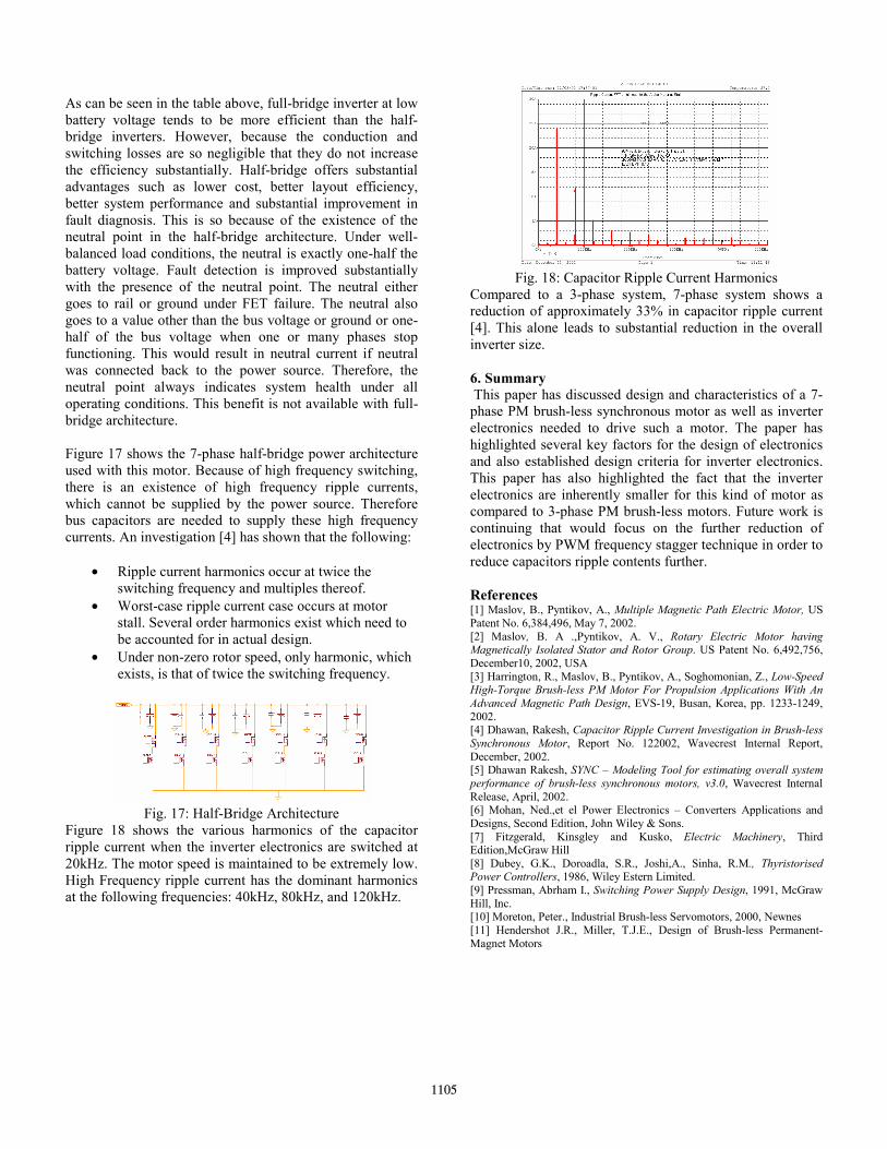
Figure 18 shows the various harmonics of the capacitor ripple current when the inverter electronics are switched at 20kHz. The motor speed is maintained to be extremely low. High Frequency ripple current has the dominant harmonics at the following frequencies: 40kHz, 80kHz, and 120kHz.
Fig. 18: Capacitor Ripple Current Harmonics
Compared to a 3-phase system, 7-phase system shows a reduction of approximately 33% in capacitor ripple current [4]. This alone leads to substantial reduction in the overall inverter size. 6. Summary This paper has discussed design and characteristics of a 7-phase PM brush-less synchronous motor as well as inverter electronics needed to drive such a motor. The paper has highlighted several key factors for the design of electronics and also established design criteria for inverter electronics. This paper has also highlighted the fact that the inverter electronics are inherently smaller for this kind of motor as compared to 3-phase PM brush-less motors. Future work is continuing that would focus on the further reduction of electronics by PWM frequency stagger technique in order to reduce capacitors ripple contents further. References [1] Maslov, B., Pyntikov, A., Multiple Magnetic Path Electric Motor, US Patent No. 6,384,496, May 7, 2002. [2] Maslov, B. A .,Pyntikov, A. V., Rotary Electric Motor having Magnetically Isolated Stator and Rotor Group. US Patent No. 6,492,756, December10, 2002, USA [3] Harrington, R., Maslov, B., Pyntikov, A., Soghomonian, Z., Low-Speed High-Torque Brush-less PM Motor For Propulsion Applications With An Advanced Magnetic Path Design, EVS-19, Busan, Korea, pp. 1233-1249, 2002. [4] Dhawan, Rakesh, Capacitor Ripple Current Investigation in Brush-less Synchronous Motor, Report No. 122002, Wavecrest Internal Report, December, 2002. [5] Dhawan Rakesh, SYNC – Modeling Tool for estimating overall system performance of brush-less synchronous motors, v3.0, Wavecrest Internal Release, April, 2002. [6] Mohan, Ned.,et el Power Electronics – Converters Applications and Designs, Second Edition, John Wiley & Sons. [7] Fitzgerald, Kinsgley and Kusko, Electric Machinery, Third Edition,McGraw Hill [8] Dubey, G.K., Doroadla, S.R., Joshi,A., Sinha, R.M., Thyristorised Power Controllers, 1986, Wiley Estern Limited. [9] Pressman, Abrham I., Switching Power Supply Design, 1991, McGraw Hill, Inc. [10] Moreton, Peter., Industrial Brush-less Servomotors, 2000, Newnes [11] Hendershot J.R., Miller, T.J.E., Design of Brush-less Permanent-Magnet Motors
1105