Sevcon MOS90 DC Traction and Pump Controller Datasheet1-1734225600
41
Tech/Ops PRODUCT BULLETIN MOS90 RANGE The new Sevcon MOS Range of D.C. Traction and Pump Controllera combines the latest state-of-the-art Mosfel and Microprocessor technologies. The result is a highly efficient and flexible range of controUers for small to medium sized electric vehicles such as pallet. warehouse. reach and low capacity fork 11ft trucks plus personnel carriers. The powerful microprocessor used in the MOSSO range offers advanced features previously unavailable in such a compact controller. PRODUCT RANGE VOLTAGE MAXIMUM CURRENT 24-4BV 1BO-600 AMPS USER/MANUFACTURER BENEFITS: Quiet operallon Increased battery shift life Increased motor life Increased conlaelor tip life Simple Installation plus reduced set up time Reduced maintenance troubleshooting time Reduced peripheral hardware- costs Waterproof Suitable for cold storage applications Designed to meet U,L. and E.E.C. Standards Sevcontrol I) Te-ch/Ops Sev{'Qn The microprocessor software facilities within the MOSOO range allow. significant number of features to be bullt into the Controller ellminating additional hardware. FEATURES: OPTIONS: Tripk faibafp Contactor chopping across vo!tagp rangp Built-in diagnostic L.E.!). Environmental protection Unckrvoltage protf'ctioll Ramp start OvertelllpcrattllT l'utba('k COlllroHe[ input protedl(lll Built -in contador ",uppressioll Mllllipk i\{'(Til'ratO[ inputs At'('t']('rat(H" billlre c\ejcctiOl] Spc('d Clltback Bypa,.,s Field WeakeJlillg Bdly switch control Seat switch lilller Hev{'rs{' battery protection i'uw{'r s\{'er delay Constant speed (paknt pending) Pump controllers (up to programmahlt' speeds) •••••• 11111111111 .. SpecificatiOilS ('ontitlued overleaf
-
Upload
jay-murphy -
Category
Documents
-
view
2.496 -
download
482
description
Sevcon_MOS90_DC_Traction_and_Pump_Controller_datasheet
Transcript of Sevcon MOS90 DC Traction and Pump Controller Datasheet1-1734225600
Tech/Ops PRODUCT BULLETIN
MOS90 RANGE The new Sevcon MOS Range of D.C. Traction and Pump Controllera combines the latest state-of-the-art Mosfel and Microprocessor technologies. The result is a highly efficient and flexible range of controUers for small to medium sized electric vehicles such as pallet. warehouse. reach and low capacity fork 11ft trucks plus personnel carriers. The powerful microprocessor used in the MOSSO range offers advanced features previously unavailable in such a compact controller. PRODUCT RANGE
VOLTAGE MAXIMUM CURRENT
24-4BV 1BO-600 AMPS
USER/MANUFACTURER BENEFITS: Quiet operallon Increased battery shift life Increased motor life Increased conlaelor tip life Simple Installation plus reduced set up time Reduced maintenance troubleshooting time Reduced peripheral hardware- costs Waterproof Suitable for cold storage applications Designed to meet U,L. and E.E.C. Standards
Sevcontrol I) Te-ch/Ops Sev{'Qn
The microprocessor software facilities within the MOSOO range allow. significant number of features to be bullt into the Controller ellminating additional hardware.
FEATURES:
OPTIONS:
Tripk faibafp
Contactor chopping across vo!tagp rangp
Built-in diagnostic L.E.!).
Environmental protection
Unckrvoltage protf'ctioll
Ramp start OvertelllpcrattllT l'utba('k
COlllroHe[ input protedl(lll
Built -in contador ",uppressioll
Mllllipk i\{'(Til'ratO[ inputs
At'('t']('rat(H" billlre c\ejcctiOl]
Spc('d Clltback
Bypa,.,s
Field WeakeJlillg
Bdly switch control
Seat switch lilller
Hev{'rs{' battery protection
i'uw{'r s\{'er delay
Constant speed (paknt pending)
Pump controllers (up to ~l programmahlt' speeds)
•••••• 11111111111 .. SpecificatiOilS ('ontitlued overleaf

r-l=~~~========================~~~~~~m O.27~
Sevcontrol .... lllnIDIlI 0
1I11111111111 •• n •••• IOJIUO:>A8S e _L_ M l40mm
mm Inch mm I,oh 5. 1"
24/36v 1A0590 °A" 213 8.38 13J 5.24 1.40590 "6" 213 8..38 '" 5.24 1010590 ·C· 254 10.00 174 6.BS
24/-48V 1.40S90 "6" 258 10.16 17' 7.00 1.10590 ·C· 283 11.14 20J 8.00 MOS90 "D" lJ6 13.23 256 10.07
Outline Specification: MOS90 RANGE
Volu,e:
Current: ContiD.uous Current:
Temperature:
Range:
OPTIONAL EgUIPMENT: CaHbrator Unit:
AdjUllter Module:
Acceuorlea:
MOS9OA MOS90B
24-4SV 24-4SV
ISOA 27M
7M 12M
OperatlngAmblent -30°C+4QOC
Storage -40"C + 9O"C
Provide. dJJltal adjutment of: Current limit Plugging level Accelerator delay Creep speed Maximum & cutback speed Bypass & field weakening levels Power steer timer Seat switch timer Uft speeds (pump controllers)
MOS9OC
24-4SV
400A
17M
Aleo act ... Dilltal Volt Meter me_1II'InI: Battery volts Motor volts Motor current Heatslnk temperature Vehicle diagnostics
Provides analog adjuatment of controller parameten
MOS90D
24-4SV
600A
22M
Full range of accelerators. contactors and contactor pane .. etc.
------- Note: This product bulletin is an outUne specification only. For specific appUcation data, tbe full enatneerlng specifications available from 8eVCOD should be ued.
Sevcon i. constantly atrivln& to improve ita product. and reserves the rlfht to alter speclflcation. without Dotice.
Tech/Ops
Sevcon Ltd Gateshead England NEll OQA
Tel: (0191) 487 8516 Telex: 53328 Fax: (0191) 4.824223
Sevcon SA Paris France 95100 Tol: (1) 3410 95 45 Telex: 698505 F",,: (1)_3410 6138
Sevcon Inc. Burlington, Mass U.SA 01803 Tel: (617) 272 3612 Fax: (617) 272 1953
Prmted In U. K. I P&S 12191
CONTENTS
INTRODUCTION & CONTENTS
SAFETY
TECHNICAL SPECIFICATIONS
FEATURES
INSTALLATION & MECHANICAL DRAWING
POWER WIRING - TRACTION
CONTROL & ACCELERATOR WIRING - TRACTION
ADJUSTER & CALIBRATOR
DIAGNOSTICS
PUMP CONTROLLER
APPENDIX I
APPENDIX II
APPENDIX III
APPENDIX IV
APPENDIX V
APPENDIX VI
APPENDIX VII
APPENDIX VIII
CALIBRATOR - MEASUREMENT & DIAGNOSTICS
FAULT FINDING FLOW CHARTS
SAFETY BUnON - METHOD OF OPERATION
APPLICATIONS GRAPHS
CONTACTORS AND FUSES
SPARE PART NUMBERS
SAMPLE PUMP CONTROLLER WIRING
SAMPLE TRACTION CONTROLLER WIRING
SECTION 1
SECTION
2
3
4
5
6
7
8
9
10
APP.I
APP.II
APP.III
APP.IV
APP.V
APP.VI
APP. VII
APP. VIII
This manual covers all MOS90 units produced from serial no. 0591---- onwards. For details of earlier units, please consult Sevcon.
Sec. 1-1
Rev5.1/92

THE SEVCON MOS90 CONTROLLER
1.1 Thank you for buying a controller from the SEVCON family of MOS90 pump and traction
controllers. These controllers are designed with you the user in mind. They provide easy
installation, many new features not available before on DC motor controllers, and diagnostics of
drive system faults. They are designed and manufactured to the highest quality standards for long
life and low failure rate. Both pump and traction controllers are available which use the most
modern and efficient semiconductors available (MOSFETS), coupled with a state of the art
microprocessor system that allows more features per controller than ever before.
1.2 This manual has been specially prepared to make installation of your MOS90 controller easy and
trouble-free. It outlines all the major facilities available with this outstanding new controller.
1.3 If you have any questions or suggestions about this manual please contact any of the subsidiaries
of Tech/Ops Sevcon where our engineering staff will be happy to provide you with all possible
assistance.
Sec.1-2
Rev4.11.91

SECTION 2
SAFETY
2.1 Electric vehicles can be dangerous. All testing, fault finding and adjustment should be carried out by competent personnel. Where possible, the drive wheels should be off the floor and free to rotate during the following procedures THE VEHICLE MANUFACTURERS MANUAL SHOULD BE CONSULTED BEFORE ANY OPERATION IS ATTEMPTED.
2.2 The MOS90 controller contains a triple failsafe system to give the highest level of safety. If the green diagnostic light emitting diode (LED) is not illuminated or flashes on and off, the safety circuit has tripped and the truck may not drive.
2.3 To ensure continued safety of the MOS90 system, the failsafe circuit should be checked whenever the truck is serviced. The maximum period between checks should not exceed 3 months.
2.4 BATTERY MUST BE DISCONNECTED BEFORE REPLACING OR ATTEMPTING ANY REPAIRS OF THE CONTROLS.
2.5 Pin 13 must be grounded if not being used as speed control input.
2.6 Note for 24/48v units without a line contactor fitted, never connect a battery to the controller with its vent caps removed, as an arc may occur due to the controller's internal capacitance when it is first connected.
2.7 Before handling controller cables on 24-48v units, disconnect battery and connect B + and Bterminals via a t OR ohm 25 watt resistor to discharge the internal capacitor.
FAILSAFE CHECK
2.8 Ensure drive wheels are clear of the floor and free to rotate.
2.9 Switch on, release brake and select drive, wheels should rotate and green LED on controller give a steady illumination.
2.10 Switch off, disconnect battery and connect A and B- terminals with 10mm2 or greater, cable, ensure no other fault that would allow drive.
2.11 Reconnect battery, switch on key with direction in neutral. The LED should flash 3 times. Select a direction and check that direction contactors do not close and wheels do not rotate.
2.12 Switch off at key, remove A/B- connection switch on at key. Reselect power up sequence, LED should now illuminate and truck wheels rotate.
IF THE TRUCK DRIVES IN 2.11, THE CONTROLLER IS FAULTY AND MUST BE REPLACED.
2.13 NOTES:
2.13.1 As blowout magnets are fitted to contactors, ensure that no magnetic particles can accumulate in the contact gaps and cause malfunction. Ensure that contactors are wired with the correct polarny to their power terminals (as indicated by the + sign on the top moulding).
2.13.2 The MOS90 MUST NOT be used with permanently connected on-board chargers or damage to the system may result.
Sec.2-1
Rev4.11/91
SECTION 3
TECHNICAL SPECIFICATIONS
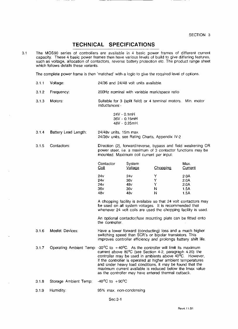
3.1 The MOS90 series of controllers are available in 4 basic power frames of different current capacity. These 4 basic power frames then have various levels of build to give differing features, such as voltage, allocation of contactors, reverse battery protection etc. The product range sheet which follows details these variants.
The complete power frame is then 'matched' with a logic to give the required level of options.
3.1.1 Voltage:
3.1.2 Frequency:
3.1.3 Motors:
3.1.4 Battery Lead Length:
3.1.5 Contactors:
24/36 and 24/48 volt units available.
200Hz nominal with variable mark/space ratio
Suitable for 3 (spm field) or 4 terminal motors. Min. motor inductances:-
24V-0.lmH 36V - 0.15mH 48V - 0.25mH.
24/48v units, 15m max. 24/38v units, see Rating Charts, Appendix IV-2
Direction (2), forward/reverse, bypass and field weakening OR power steer, i.e. a maximum of 3 contactor functions may be mounted. Maximum coil current per input:
Contactor System Max. QQiL Voltage Chopping Current
24v 24v Y 2.0A 24v 36V Y 2.0A 24v 48v Y 2.0A 36V 36v N 1.5A 48v 48v N 1.5A
A chopping facility is available so that 24 volt contactors may be used on all system voltages. It is recommended that whenever 24 volt coils are used the chopping facility is used.
An optional contactor/fuse mounting plate can be fitted onto the controller.
3.1.6 Mosfet Devices: Have a lower forward (conducting) loss and a much higher switching speed than SCR's or bipolar transistors. This improves controller efficiency and prolongs battery shift life.
3.1.7 Operating Ambient Temp: -30°C to + 40°C. As the controller will limit its maximum current above 800C (see Section 4-2, paragraph 4.20) the controller may be used in ambients above 40°C. However, if the controller is operated at higher ambient temperatures and under heavy load conditions, it may be found that the maximum current available is reduced below the Imax value as the controller may have entered thermal cutback.
3.1.8 Storage Ambient Temp: -40°C to +90oC
3.1.9 Humidity: 95% max. non-condensing
Sec.3-1
Rev4.11.91

Controller Family(8)
Basic 24v
Options 24v
Basic 24/48v
Options 24/48v
3.2 NOTES:
MOS90 CONTROLLERS - PRODUCT RANGE
Frame Size
MOS90A MOS90B MOS90C
MOS90A MOS90B MOS90C
MOS90B MOS90C MOS90D
MOS90B MOS90C MOS90D
(1 )
(2)
(3)
(4)
(5)
(6)
(7)
(8)
Current Rating (4) Mechanical
Notes (1 ) (2) (3) Power (6) (5) 2 Min 1 Hr Bypass Conns. W L H Remarks
O/C
180 75 - 4 (10mm2j 140 213 63 Direction contactor 270 125 - 4 (10mm2j 140 213 63 drivers only. 400 175 - 4 (25mm2j 140 254 63 Reverse battery
protection (7).
180 75 360 5 (10mm2j 140 213 63 Direction contactors 270 125 540 5 (10mm2j 140 213 63 + any 2 of Bypass 400 175 800 5 (25mm2j 140 254 63 Field Weakening or
P. Steer. Reverse battery protection (7)
270 125 - 4 (10mm2j 140 258 63 Direction contactor 400 175 - 4 (25mm2j 140 283 63 drivers only. 500 225 - 4 (35mm2j 140 336 63 (600)'
270 125 540 5 (10mm~ 140 258 63 Direction contactors 400 175 800 5 (25mm2 140 283 63 + any 2 of Bypass 500 225 1000 5 (35mm2j 140 336 63 Field Weakening or (600)' Power Steer.
* 1 minute current 1im~ rating.
Current limit ratings are with the controller at a max. of 60% ON.
1 hour ratings are at any %ON up to maximum and assume adequate contact cooling of the controller.
This is the max. settable over current value, it is usually set at 1.5 times current limtt - beware contactor and motor ratings'
These figures assume an ambient of 25°C.
The optional contactor/fuse plate increases the overall height to 125mm.
5 power connections are required when bypass is fitted (options units only).
Reverse battery protected controllers only give this protection if used with the correct contactors - See wiring drawings and contactor section (Section 6).
24 volt controllers may be used at 36 volts with a derating (refer to App. IV-2).
Sec.3-2
Rev4.11/91

4.1 Encapsulated Enclosure:
4.2 Triple Failsafe Mechanism:
4.3 Accelerator Failure Detect:
4.4 Bypass Option:
4.5 Bypass Dropout:
4.6 Speed Control Interfaces:
4.7 Accelerator Characteristics:
4.8 Max. Speed:
4.9 Cutback Speeds:
4.10 Constant Speed Option: (Patent pending)
4.11 Plugging:
4.12 'Belly' Swttch option:
4.13 Under-voltage Protection
SECTION 4
FEATURES
For maximum environmental protection and tamper-proofing .
Using both hardware and software techniques to give rapid action and cross checking at each power up.
Prevents 'runaway' due to any accelerator lead becoming detached or incorrectly connected. Only available when 5K variable resistor or accelerator type 656/12013 is used (input pin 14).
An addttional contactor that operates wnh full throttle and, when the delay has run out, to bypass the MOSFETS and allow absolute maximum speed and efficiency. Bypass will also operate if the unn is in current limtt for more than 1 second at full throttle.
Releases the bypass contactor if the preset current is exceeded and retums to the pulsing mode of operation: recycle direction through neutral to re-engage bypass.
Various speed control systems may be used, i.e.:-
4.6.1 Sevcon Linear Accelerator, type 656/12019 OV min. speed, 5V max speed.
4.6.2 Sevcon Linear Accelerator, type 656/12013 3.5V min. speed, OV max. speed.
4.6.3 Variable resistor 5K ohm min. speed, 0 ohm max. speed.
4.6.4 Centre tapped potentiometer (1 K + 1 K) or (10K + 10K) OV min. speed, 5V max. speed.
4.6.5 Hardellet type module (uses 10.5V feed from pin 3).
Non linear relationship between accelerator position and motor voltage to give enhanced control in low speed travel (see App. IV-3).
Limns the top speed of the vehicle.
2 speeds externally selectable and adjustable to required level.
This is available as a Control software option. The motor speed is monnored by means of software and held constant at the accelerator demand setting, independent of load. To use this option the motor characteristics are pre-set into the software.
Constant current type, adjustable. Varied by footpedal or hand throttle posttion as standard. Software option - no variation wnh footpedal or hand throttle.
Used to give operator protection on 'Walkies' in line wnh the EEC Directive (see Appendix III).
The controller cuts out if'the battery dips below 13v, re-cycle through neutral to restart.
Sec.4-1
Rev4.11/91

4.14 Reverse Battery Protection: (RBP)
4.15 Input Protection:
4.16 Contactor Suppression:
4.17 Contactor Drives:
4.18 Anti-Rollback:
4.19 Start Sequence:
4.20 Overtemperature Rollback:
4.21 Field weakening option:
4.22 Static Return To OFF: (SRO)
4.23 Power Steer option:
4.24 Seat Switch option:
4.25 Diagnostic LED:
4.26 Adjustor & Calibrator:
4.27 Hours Counter:
4.28 Service Log:
4.29 Electric Brake Option:
Provided as standard on 24v systems, requires polarity sensitive line contactor on 24vj48v systems.
All customer control wiring inputs are protected against connection to B + or B-. Calibrator adjuster socket is not protected.
Built into logic unit for all contactors controlled by logic unit.
May operate at system voltage or via a chopping system which reduces the coil voltage for use with 24 volt contactors; stabilised against battery variations. Customer selectable. Chopping is recommended whenever 24 volt contact or coils are used. Chops at about 18 volts.
Basic controllers have direction contactor drivers only. Options units have direction and 2 other contactor drivers. These drivers may be configured as any 2 of Bypass, Field Weakening, Power Steer, by software option.
Allows full current when drive is reselected without a direction change, even if the vehicle is rolling backwards.
The unit must be in Neutral at Key ON, or drive will not be enabled.
When the heatsink exceeds 80DC the current limit will linearly cut back to zero at 90DC.
An additional contactor that closes at full throttle to increase top speed by means of a resistor in parallel with the motor field, or a tap on the motor field. Contactor drops out when motor current exceeds preset level.
Requires direction to be selected before FS1, or FS1 and direction, within 2 seconds: The direction switch must be in the neutral position before the keyswitch is turned ON.
Software selectable in place of field weakening or bypass. Delay adjustable between 0 and 50 seconds in 1-second increments. Delay triggered by releasing FS 1 . When FS 1 is not wired to the controller, the delay is triggered in neutral.
Software selectable in place of belly switch input. Delay adjustable between 0 and 5 secs in 0.1 sec increments. After opening seat switch, recycle direction, through neutral, or FS1 to restart.
A single LED gives comprehensive diagnostic information. LED on equals controller healthy. LED off indicates a faulty controller. A flashing LED, 2-8 flashes, indicates a fault external to the controller.
Straightforward, hand-held calibrator unit for digital adjustments or traditional potentiometer adjuster unit. Calibrator also incorporates unique DVM feature and harness check facility.
Hours counter records controller pulsing time up to 65,000 hours.
Used in conjunction with calibrator unit, records maximum battery voltage and maximum and minimum temperatures controller has experienced.
Enabled after delay in neutral, and in conjunction with 'belly' switch.
SecA-2
Rev4.11/91

SECTION 5
INSTALLATION
5.1 The controller should be bolted down to a flat (O.2mm max. deviation) paint free surface that has been ligh~y coated with a thermal transfer compound, such as MS4 or Dow Corning #7, by the 4 bolt holes provided. Care should be taken not to trap any wires, etc., under the controller. The mounting surface MUST be a substantial metal section of the truck for the full controller ratings to be achieved.
5.2 Power connections should be made with flexible heat resisting cables of suitable cross-sectional area for the current to be carried. These should be terminated in soldered or crimped lugs attached to controller and the contactors. Note that nuts and washers are not supplied for the M8 connections on the controller. A battery disconnect switch should be used (EEe Directive).
5.3 Albright SW88 (MOS90 A), SW182 (MOS90 B & C) and SW202 (MOS90 D) are specified for use with the controllers when 4 terminal motors are used. The equivalent single pole N.O. contactors (SW80, 180, 200) are used for bypass and pump functions The field weakening contactor (if used) may be of lower current rating than direction or bypass, viz:- it is possible to use an SW80 field diversion contactor with SW182 direction contactor. When alternative manufacturers contactors are used, coil currents pull in/drop out times should be investigated to ensure compatible operation.
5.4 Split field (3 terminal) motors can use single pole normally open type contactors for direction function with controllers for 24v systems, BUT, controllers for 24/48v systems require changeover contactors OR double pole normally open types (if armature field junction connection available) to utilise the Reverse Battery Protection (RBP) feature.
5.5 The contactor mounting plane can affect performance; contactors should never be mounted with their terminal studs vertically down. For further applications information on contactors, please consult SEVCON
5.6 The controller may be supplied as a stand-alone unit, or pre-wired onto a baseplate with contactors etc. If the controller is 'stand-alone', the control wiring should be terminated at the Molex 0.15" control socket If a 'panel' is supplied, the control wiring connector is usually an AMP 15 way MATE-N-LOK type. The harness portion of the connector can be supplied with the controller as a 'loose equipment kit'.
5.7 Control wiring connections should be made using 1.00mm2 (AWG #) or equivalent stranded wire. The correct pressure release crimping pliers MUST be used for long term connection reliability.
5.8 The main battery cable should be fused with a suitable air-break fuse. The keyswitch line must also be fused at a level not exceeding 10 amps.
5.9 Hour meters MUST NOT have their negatives returned via the direction contactor drivers (Pins 1 & 10) as the controller will not function.
5.10 Pin 13 on control input must be connected to B-ve if not being used as speed control input.
Sec.5-1
Rev4.11/91

I
(J)
~ '" '"
63 -------,
~G)tJ
is' < .. ~
1> t:l L
'" >< -<
n o z -< ;u o
r r f"'l t:l ~
Z -u c -<
'" o n >< f"'l -<
,--r-' = ~ ::!t8r
'V
r
Sevcont rol •••• IIIIIIIII~OS9q [$ ,
~6so"IIIIIIIIII... lOll UO:)A as I
.• 0 ~-,
$' -- -~L-; 'W CONTROLLER "
, MM INCH'S MM INCH'S 24V ONLY MDS 90 'A' 213 8,38 173 6,81
MOS 90 'B' 213 8,38 173 6,81 MOS 90 'C' ' 254 10,00 214 8.43
; 24!48V MOS 90 'B' 258 10,16 218 8,58 1$ ;
I
L MDS 90 'c' 283 I 11.l4 243 9,57 MOS 90 'n' 3.36 I 13,23 29§. .11.65 _
~" I .oj 'umoo ~'nMOC.,. 'W L"1 !
~ f "
:;:: o en CD o -4 Jl » C) ::j o z C) o Z
140 -4
-.J
7
Jl o
,F , m I Jl
:;:: m C) :I: » z C) » r-
C Jl
~ 'Z
"

(f) CD
" i;n :..
ii' <
"' <a
L J o><o-B+
'V~n RE. F"'t(D
24V FAMILY CIlNTRDLLERS REVERSE BATTERY PROTECTED PO'JER CONNECTIONS <BASIC)
s " »+ NOTE: C£lNT 6CTIlIl crN£clImIS:
I 1 ~~KmK~ THIS VAY FOR REVERSE BATTERY PROTECTION
-lEi J-
B-
S
FIElD VEAK
-1~~
24V FAHrLY CONTROLLERS REVERSE BATTERY PRIlTECTED POVER CDNNECTIDNS
»+ NOTE: C£lNT 6CIIlB j;1JNI.£j;IIllNS SHOVING BYPASS ~ FIELD
, VEAKENING CIlNNECTIDNS
CDNTRDLLER MUST BE VIRED THIS VAY FOR REVERSE BATTERY PRDTECTIDN
M ~ ---,
I I
;1 BYPASS
B-
NOTES>- 1) CIlNTACTIlR PIJ'w'ER CIRCUIT CONNECTIDNS ARE POLARITY SENSmVE BECAUSE
BLIJ'w' -DlJT MAGNETS ARE FITTED. NIlTE ' +' SIGN eN CDNT ACTOR MOULDINGS
~ SEE CIlNTACTIlR SECTIlJ'j «(Ii>P.V>
'3: 0 0 CD 0
;j > n -l 0 Z
n 0 z -l JJ 0 r r m JJ
I"C 0 ::;: m JJ
!::;: , -:!! z G')
0 ;
ie;) JJ > 3:
~ 13:
0 -l 0 JJ
'0 (f)
m () :::j 0 Z (J)

U>
'" n '7'
"
r-------_, ... ,-0:><Cr-B+ .---------_, ... ,.---.0:><Cr-B+
1!' < "'"
"'
I I L __ -= .... _.
FIELD 'W£Nf.
s
THIS 'JlRlNG ARRANGEMENT VILl DETECT Nfr LEAKAGE IIE'NEEN FJELD AND ARMATURE IJ' TI£ IIlTllR AND TRIP TI£ F AILSN'E SYSTEM AS 10 RESULT. <SEE IoPPlL SECTION !L4)
24/48V FIoMJLY CONTRIlLLERS NIl REVERSE BIo TTERY PROTECTION I«!TE ClIfiACTII! gH£CTl!)lS SKIVING BYPASS .. FJELD
I 0- ___ , 'w'EAKENING CONNECTIONS
I I :1 -= -j
... B-
I I L __ -= .... _. FJELD 'IiEIoK
s J+
I
-j ...
M
THIS 'w'lRING IoRRNoIGEMENT 'w'1LL loLL[)\{ TI£ USE IJ' 10 IIlTllR IJITH stJ4E LEAKAGE BET'ot'EEN FJELD AND ARMA TIJRE
0----, I I :1 JYPASS
B-
iIIlTESo- 1> CONT 1oC~ P[)\{ER CIRCUIT CIHIECTIIJ'jS loRE PILIoRITY SENSITIVE BECAUSE BLD'w'-wr MAGNETS loRE FITTED. NIlTE '+' SIGN ON CDNTIoCTOR MDULDINGS .. SEE CONTIoCTOR SECTION (APP.V)
I ;:
'0 en
,CD o -i ::tI ,» o -i 6
,z '0 o
Z -i ::tI
,0 r-
, rm ::tI
"'0 o ::E m ::tI
:§ ::tI Z G'>
o i> G'> ::tI » ;:
.. -i
;: o d ::tI en

en ~
'" '"
I o><o__B+
11 REV .1 FWD
r-------------~I~i~o><o__B+ .....-----------.,-0><0__ B+
s ...
-it} I-
<I' <
" §
24V fAMILY CDNTRILLERS
REVERSE BA~Y PRlJT£CTED
PD'WER aH£CTIlIjS SKI'JJNG
BYPASS IF USED
REV
s
FWD REV
24/48V fAMILY C!lNTRI'J i F'RS
NOT REVERSE BAnERY PROTECTED
PIlYER CDNNECTlllNS 'JITH
BYPASS IF USED
NOTE CIlITACT!!R C!lt£CTJOO
s
FWD
24/48V fAMILY C!lNTm I F'RS
PD'WER 'WIRING 'JITH DPTIlJIS
TD GIVE REVERSE BATTERY PROTECTION '.'HEN USED
'WITH D.P. NID CDNTACTOR
" I ~ I'! I L-l I" ---, I I
-1~ ~ ;1 aYPASS ·1 aYPASS -1~~ I B-B-
IIlTESt- 1> carr ACT!!R PIlYER CIRCUIT CDNNECTIIlNS ARE P!LARITY SENSmVE BECAUSE
BUl'w'-aJT MAGNETS ARE nnE». NOTE '+' SIGN ON carrACT!!R IOJLDINGS
.. SEE CDNT ACTOR SECTIIJoI <N>P. V>
i'.~
3: o en '" o
l-i :0 :I> (") -i o Z
(") o Z -i :0 o
'rrm
,:0
"0 o ::E m
I :c : ::E !~
Z G'l
C I i> ,G'l
:0 :I> 3:
~ (jj "0 r-:::j
" m 5
1-
I 3: o ~ en

en '" " -;' ~
lEV FUSE lEV STIIIrT IV FUSE ~lIU.y
1 • 1+ 1 R
1+ 1 I ,.. ...... Jar. , ..... , ••• , kEY FUSE tam, 0000 _
2 r ICEY 3. 4. 5 6 7. B 9. F\III
10 11. 12. ~!:tcm EWT!!
I ij 1st 16t 17. ...
!tSJC QIfiIfI. ymy; SUITAIl£ flit IUJIE ~ TRlDC IN'mII..DCK SVI1O£S <FSI. __ ric.) SIGLII
IE aH£CTEII IN SEIIIES AT 'X-X' VALUE EF SPED a::tmtI1. yMJAll£ iESlS i 1M ..aT IE ~ MAX RESISTANCE GIVES MIN SPEED. L!.CINECT PIN (2) m 1+ FIll :w. AND oil VlL T ClJlTIoCTIIR am.s. L£AVE lHOiIi€ClU FIll 24V am.s <aIIl. DIJ'PINIi)
2 en\) ICEY 2 F DIR 3. 3. 4. 4. 5 5 6 6 7. 7. B B. 9 SJt.II. 9. F\III
10 10. 11. F\III 11. 12 12. 1 13 1 1 1 1 1 SEAT IV 1 tSPED 17 FnlI • 17""'FnlI , , ....
CDR POYER STEER> .. rrT1DIS CDt'l'III VIIUMi SUITAILE flit RIM 1:»1 TRUCIC vmt s.R.D. .. SEAT S\IITCII VJRINIi,
EIlIIEII nPA$S NIDIIJIt FnlI ~ IIo\Y IE aN£C1D).
• _ REMAINS THE SN£ IF THE FnlI IIlVEJISDI
ClJlTIoCTIIR IS SlFTVME AU..IlCATD m POYER SlUlI L!.CIIIIiECT PIN (2) m 1+ FIll :w. AND 48 VlL T ClJlTACTIlR am.s. L£AVE IN:INECTED f1IIt 24V am.s <CIIIL. DIJ'PINIi)
rptn)§ QIIDIIL V'P"i PLUS IELL Y S\iITDt [II EMERGENCY SYTTa1. SUlTAILE f[JI VAI.JClE TRUCI(
DIIIIIE IS 311 PIIIN TYPE. .IIIIEt::. THo\T SVTTOIES MUST lIlT IE aH£CTD IN LlNE IET'tIEDI 11£ ICEY .. DIR£L 111»1 S\ITTO£S e.g F'Sl. SEAT SVTTOO [II THE EIEiG:Ht. IIIT1DI IIIL.L lIlT F\.IICTDI. L!.CINECT PIN (2) m 1+ f[JI :w. AND 48 VlL T ClJlTACTIlR am.s. L£AVE LJC:IHIECTED f[JI 24V aILS <aIIl. CIIPPIII&)
IIITD>-
:i' < .. "'
L PIN 16 MUST IE aH£CTEII m lOVE IF A SEAT S\IITCII IS lIlT lJSEI).
l!. DtSaINNECT PINS , .. 12 IF s.R.D. IS lIlT ..... 1IW1l
(f) m
~ o z ....
C)
o z ~ o ,....
~ ;!;! z
'" C)
o z z m C) -I 6 I~

(J> (1) (")
.... '"
REV START S'J
1~~~~~~R~_ ~. 2 COlT CIU' IN'\IT F t"D1R' <F"S\)
~ ... ~ .8+ 14"'9---,
3~~ 4 T 5 j)S""'--.llDLL._---'
~~~~~==~~~ 8 ~fYl! 1!f'\!T
9~ 10~C[!lL IN
11~ 12~
l~!)--;,C-C-f1-ER-AT-OR-----~-ts-PE-ED--,1 16~ 5 17~
-+-----4---4Ie B-
BASIC CONIRtl. \mUNG YUH SPEED LIHIT SUITABLE
FOR \r'ALKIE []R RIDE-DN TRUCKS. BYPASS L nELD
"'EAKENING ClF FITTI:D) ARE !NHlBITED "'HEN IN SPEED L!MJT. lIJIEI::. THAT FSI OR SIMILAR S"'ITO£S MUST NCT BE USED 'WI£N A BELLY S'o'ITCH IS nTTED .6 CONNECT PIN (2) m B+ FIR 3& AND 048 vm. T CONTACTDR CDlLS, LEAVE UNCONNECTED FOR 24V COILS
(COIL CH!!PI'!NG)
~ <
'" ~
13~ j e,-sr.wDltRP '" pm OR YMTAP E RfSLSTDR
IIUt£AR: FOOl PElJAL a-::J P!N!lJTS
START t:. 'I' IIIU BE USED ! lB t:. START SIJ!TCH
S;ITCH IT'" ~ ~13 "'[' MAX PUSH ~ ~. MAX SPEED ne M e.
! INEM fTTTTP[DA! 6»J1?Ot9
1iW90 TRACK ~9® RESISTANCE
SPEED ~ MIN ,- e13 IDK MAX t fl el3
'" MAX SPEED e. MAX !lIP vm. TS B-
lK+1K CI PDr PQT$ 0Df'R TH.\H 5K
0IF Tl£ SRI] FLN:TlI»I IS JIEIH(i USED TI£N PlN 9 IS I'IlT AVAllLAIlLE FIR USE AS AN ACCEl..ERA TtR stI'PI. Y. IN THIS CASE C!HIECT Tl£ POSItIVE END I:F Tl£ .ccELEAATDR PI!T m PIH 3 VIA A 470 _
1/2 "'An RESlSIIR.
SOCKET fDJSING CYIE'WED FROM HARNESS SIIIO
~ .. -----~
@COOoooooooooooool 17
pmFTT rnam I rp - CJIfTIOI vnrtH'j PIN rutS
1. REVERSE aM'M:". am.. DRf\IE.
2. tnfTACTtII OIPPING ~ - a:NIECT Ttl 1+ IJHEM USDIi 3& IlH1J ..a VII... T am...s. LLA VE I..N::I:N£CTED n:R 24 VCl..T am.s.
3. 1D va.. T SI.JIfIt. y GWtDEl.L.£T J4llJI.A..£S)
4. SPEED LIMIT 1 - CIH£CT 10 1+ n:R frrI:RMAL tFEAA Tl[fi
L.£AV£ LH::tH£CTED rI:R SPEED LIMITINi.
5. ~ nf'UT F"RCM DIREC'T'I[JoI S'w'ITD-L
6. JA TTERY + rEED F"R[Jt tcLYS'w'lTCH.
7. SPEED LDttT 2 - aH£C1 TO 1+ n::R tIlRMAL IFERA TltK L.EAVE l.KDfr£CTElI ~ SPEED l.IMITlNG.
8. FI:IN'ARD Df'UT rJt[Ji! DlR£CTl[IoI S'JITCH.
9. SlFPLY FlJif: CENTER-TN'PElI PDT ~ SJUJ. SlPPLY.
10. ~ARlI aJrffACTtJt am.. DRIVE.
1.L SPM[ DPUT .
t.2. F"Sl Df'UT ~ SJUl
13. SEVa:Jt ACCfl FRATI:R DFUT aJV-sv twt: SPEElD, caJrI£CT Tn I-VE JF trIJT USEID
14. ~ PUT NTfl f'R4 TIll n-FUT C3.5V...qv MI\X. SPEElD
15. 1YPASS/P!I'o'ER STEIlt 13fT ACTtR am..
16. Ell.Y/S£AT S'w1iQf DrfI'UT.
17. nn..DIDIVERSJIIt.IPD'WDt STEER aM'N:11It COIL
l> n n m r m ::0
~ ::0
:E :!! Z
1G'l ; l>
Z C
n ,0 ,z z
,m In , -! 10 I ::0 , "'[] ; z o
Ie I' -4 I(J>

SECTION 8
ADJUSTMENTS
8.1 The following procedure is relevant to both traction and pump controllers, except where otherwise marked. The controller can be adjusted In several ways to its desired parameters:-
8.1.1 The unit is pre-set at Sevcon's factory, but may be re-adjusted later by one of the methods below.
8.1.2 The unit may be adjusted by means of an 'adjuster' which contains 7 potentiometers. These are 'read' by the microprocessor and can be adjusted while the controller is in operation. The settings are 'memorised' when the un~ is removed. External instrumentation (shunt, ammeter) must be used with the adjuster. Only the first 7 parameters can be adjusted with the adjuster, as illustrated below. In the case of the pump controllers, the potentiometers adjust speeds 1 to 7.
8.1.3 The adjuster as 8.1.2 may be permanently connected to the controller.
8.1.4 The adjuster as 8.1.2, once set, may be plugged into a series of controllers to set each in turn to the same parameters. This is a useful feature as it allows rapid (1 second) configuration of batches of controllers. Typically the adjuster unit(s) will have its potentiometers masked off once set up.
8.1.5 A hand-held calibrator may be plugged into the adjustment socket and used to digitally increment/decrement the parameters. The present value of these parameters wiii be shown on an LCD display. Additionally, the calibrator can perform certain measurements on the controller (see diagnostics section). Removal of the calibrator again causes the controller to 'memorise' the set figures. This system gives the greatest accuracy and repeatability.
The hand-held calibrator has a bar display, operated by the SELECT button, showing parameter/measurement selected and an LCD display showing values that, provided they are parameters, may be adjusted by the +/- buttons. This unit may also be used to perform certain tests on the wiring harness and accelerator.
Additional external instrumentation is not required when using the calibrator's measurement feature.
.' .
////
SEYCON MOS90 POTENTIOMETER
MODULE (ADJUSTkR) AND CAl,..lIlRAT[]R
I
Sec.8-1
\ I T. nON
""" .... "'"'-..... ...... ..... ...... ..... ,.",.,. -KAT ...... " M .. .. n .",. .... ,... "'"
I J \
P"" ... ..... .. ... ....... ax .... .. .... ....... ... ..... .. . - ..... .. g • ..... " • ..... .. ... COUP .... ax --- "'" • ... .--
D v v SEL£CT ... "' CALIBRATOR
Sevcontrol
Rev4.11/91

ADJUSTER
8.2 Connect the adjuster to the controller as shown below:-
. DIAGNOSTIC LED
.... 9 "V
L___________________ _________ ~
The following applies to traction controllers only. For details of use with pump controllers, see Section 10-1, paragraph 10.3.
8.2.1 F~ ammeter to motor circu~, ensure that truck drive wheels are clear of floor and free to rotate. Insulate the bypass contactor tips (ij used). Switch on the controller and set the accelerator to maximum wtth the brakes applied so that the wheels cannot rotate. Adjust IMax. to give the desired current
8.2.2 With the truck drive wheels still clear of the floor, remove bypass contact tip insulation. Switch on the truck and allow to run up to full speed and the bypass contact or to close. Apply the brakes to load the drive motor until the desired current is reached. Adjust the BYPASS pot counter-clockwise slowly until the bypass contactor opens.
8.2.3 Remove ammeter and set truck on ground. Drive truck and adjust ACCEL to give acceptable 'feel'.
8.2.4 Drive truck with load and plug brake, adjust PLUG to set plugging level to suit application. Note that plugging response can be affected by accelerator position on certain controller types, so that plugging must be set with the accelerator at maximum demand.
8.2.5 Creep Speed is set by adjusting CREEP so that with the drive selected, the truck is just about to move at minimum accelerator position. This level may be set differently depending upon application.
8.2.6 Drive truck unloaded on a flat surface and measure speed. Adjust SPEED to limit speed to desired level.
8.2.7 Repeat 6 above with speed limit 1 switch input at B- and adjust SPEED 1 for desired speed level.
8.2.8 Note: Only the first 7 settings can be adjusted using the adjuster. The full list of settings is described on the next page.
Sec.8-2
Rev5.1/92

ADJUSTABLE CUSTOMER PARAMETERS CALIBRATOR
TRACTION
Parameter Min Max i Units Step Size
+- - --
MOS90ATMoS90B i MOS90C MOS90D j
i 400A I
Current Limit 50A 180A 270A 600A : Amps lOA (I MAX)
Plugging Current 50A 180A 270A 400A 750A Amps 10A (PLUG)
Accel. Delay 0.1 5 secs 5 secs 5 secs 5 secs Secs 0.1S (ACCEL)
Creep Speed 0% 25% 25% 25% 25% %VB 1% (CREEP)
Bypass Dropout 50A 360A 540A 800A 1000A Amps 10A (BYPASS)
Maximum Speed 0% 100% 100% 100% 100% % VB 1% (SPEED)
Cutback Speed 1 0% 100% 100% 100% 100% %VB 1% (SPEED 1)
Cutback Speed 2 0% 100% 100% 100% 100% %VB 1% (SPEED2)
Field Weakening 50A 180A 270A 400A 600A Amps 10A (F.wEAK) P.Steer Delay 0 50 secs 50 secs ; 50 secs 50 secs Secs 1sec (TIMER) i Seat Swttch Delay 0 5 secs 5 secs 5 secs 5 secs Secs 0.1sec (SEAT)
For details of use with pump controllers, see Section 10-1, paragraph 10.3.
\ I
1 I
CONNECT CALIBRATOR TO CONTROLLER]
•• PUMP
"'" - .....,' "'" - ...... ....... lie .... " .... ... .... .. - .. .... .. .... , "" ...... g .... , , .... " ...... , ...... ,- .. ...."" ... "" -"" .. , "" ..... ,
DIAGNOSTIC LED
MNO .. ,--.. .. ,bJT .. .,,' v ..... v ..... -- ., C£l.l BlU.f'OR ...,
Sewcontrol
Rev4.11/91
CONNECTION OF CALIBRATOR TO CONTROLLER
Sec.6-3

8.3 Connect the calibrator as shown below and power up the vehicle.
8.3.1. No LED segment will be lit and the minutes/seconds count is displayed. The hours count is displayed by pressing the' -' button and the 1 ,ODDs of hours count by pressing the' +' button as described in Appendix 1-1. Pressing the select button reverts the calibrator to its normal operation, i.e. the IMax segment will be IiI.
8.3.2 When the desired parameter has been selected, it may be increased or decreased by means of the + and - buttons on the right of the calibrator. The range of adjustments are given on a previous page.
8.3.3 Note that parameters 6, 7 and 8 (SPEED, SPEEDI and SPEED 2) may reduce current limit and ramp climbing ability.
8.3.4 For details of the measurement and test functions, please refer to the DIAGNOSTICS section.
CD J CONNECT CALIBRATOR LER~-r- TO CONTROL
~ n~llIg i F.;~
. ,b,I i .. , ......... ' .. 1... ""_Dlr!!l.J
LJ USE OF CALIBRATOR
CD POIJER UP TRUCK
ADJUST ro NEI,I VALUE
'--J) SELECT N[lJ PARAMETER
-----=-===~
SETIING PARAMETERS WITH CALIBRATOR
Sec.B-4
Aev4.11/91

SECTION 9
DIAGNOSTICS 9.1 The controller is equipped with a diagnostic system using a green LED located on the connection plate
near the adjuster socket.
ADJ SKT CONTROL VIRING SKT
~ ..... j ~ ............. .. (t)O ®
~U!lfu----rrit-~3-
DIAGNOSTIC LED
9.2 On power up the LED will be illuminated if the system is functioning correctly.
9.3 The LED is extinguished H the controller is faulty, the fuses are blown, the failsafe is not operational, the contactor driver protection has tripped, or the Mosfets fail to turn on during drive. If the contactor driver transistors are short circuit, the contactors may close but the vehicle will not drive under single fault cond~ions.
9.4 This applies only to traction controllers. See Section 10-1, paragraph 10.4 for pump controllers. The LED will flash a number of times on power up, or during running, to indicate a fault external to the controller.
9.4.1 2 flashes Incorrect start procedure fault. Both forward and reverse selected.
9.4.2 3 flashes Bypass contactor welded - recycle through neutral to clear. Contactor coil short circuit - recycle the keyswitch to clear.
9.4.3 4 flashes Direction contactor welded.
9.4.4 5 flashes Direction contactor did not close, or open-circuit motor.
9.4.5 6 flashes. Faulty accelerator input.
9.4.6 7 flashes Low battery voltage.
9.4.7 8 flashes Thermal cutback.
See Appendix II for detailed fault-finding flowcharts.
Sec.9-1
Rev4.11/91
PUMP CONTROLLER SECTION 10
10.1 The MOS90 pump controller is a derivative of the range of traction controllers which has been optimised for the control of hydraulic pump motors in electric vehicles. The same powerful single chip microprocessor, calibrator and diagnostic system are used.
10.2 Features
10.2.1 Three power frame sizes are available with current ratings of 275, 400 and 600A These units are physically the same size as the MOS90B, C and 0 units, but with only 3 connection busbars.
10.2.2 Voltage range 24-48v.
10.2.3 Reverse battery protected w~h polar~y sens~ive line contactor; capable of operation without a line contactor.
10.2.4 Up to 8 programmable speeds, with the priority of SPEED 1 highest, SPEED 8 lowest.
10.2.5 SPEEDS t -7 are active high and these inputs must be connected to B + to enable the speeds. SPEED 8 is active low to allow its use as a power steer speed. The input must be connected to B + to disable this speed and either disconnected or connected to B- to enable it.
10.2.6 Lift speed (SPEED 1) may be infin~ely variable with the use of an external 5K variable reSistor, or a 0-5v input from a linear accelerator unit.
10.2.7 Creep speed adjustable (but overridden by lower selected speed).
10.2.8 Soft start (ramp-up) delay is adjustable.
10.2.9 Current limit adjustable.
10.2.10 Additive speed feature increases % ON when speed switch 8 (normally power steer) is selected together with any other pump function. The speed increase depends upon the 'EXTRA' speed setting and gives a measure of speed compensation.
10.2.11 An inhibit input is provided which can be used in conjunction with a B.D.I. low battery signal to prevent SPEEDS 1-7 operating. SPEED 8 is still allowed to operate.
10.3 Adjustment
The pump controller may be adjusted in exactly the same manner as the traction unit. Using the calibrator, all 8 speeds, the ramp delay, creep, current limit and the 'extra' speed may be set and reset with their values being displayed:-
10.3.1 Speeds displayed as 0-100% representing 0-100% of battery voltage.
10.3.2 Ramp up delay displayed as 0.10 to 1.00 representing seconds in increments of 20mS (0.02 secs).
10.3.3 Creep adjustable between 0 and 25% of battery voltage.
10.3.4 Current limit adjustable between 50A and maximum controller rating.
10.3.5 Using the adjuster, the first 7 speeds may be set.
10.4 Diagnostics
The diagnostic system is generally as described for the traction system. The number of flashes is defined below:-
10.4.1 LED off Mosfets did not turn on. 10.4.2 2 flashes Pump inhibit input operating. 10.4.3 3 flashes Short circuit across Mosfets, or motor open circuit. 10.4.4 7 flashes Battery voltage less than 13v. 10.4.5 8 flashes Thermal cutback operating. The test sequencer function of the calibrator is generally as described for the traction controller in Appendix I, with the pump pot. (if fitted) being tested first, followed by switches 1-8, then the inhibit input.
Sec.l0-l
Rev4.11/91

L
.. ,
MOS90 PUMP CONTROLLER MECHANICAL AND POWER CONNECTIONS
+ ~
... "" 06 SOH l\a~/"2
H3~'mI.1HOJ
Sevcontrol ::::::
MOS90 PUMP CONTROLLER - CONTROL WIRING
SOCKET HOUSING (VIEVED FROM HARNESS SIDD
~o 0 00 0000000 OOOc;::;;J 1 17
I. ~ • PUll' IIKIIT ~ • 1M MX ICJRIIW..L Y Cl.DSED S\I8 a:tma:L
F'IISE e. a. ~ IGV SQ'PLY
4. ~ • sY4
~ sYI!
0 • PUll'
~ t :; CIIIT IATTo<VlII KEY IV) am.
0 aT
5. '.
!) SIr.!
~~ • !) SVI •
7. •• '. ~ NT[! ..... '!IIIt Sl.PI'L Y
~IE
~ • sY7
Je. ~ • SIr.! ,'-CHIV
aN£T TO .. IF lIlT USEII !PTD
~ ,
nit H'U'! EPA11It LIIENI NTIl ..... TIlIt .. 13.
'-r- IA Filii
!)IE -aT
sY' (: 16. ~IE
!II( .. aT rt1'1'Q II'DIATEII \lITH sY1) ~ ..
Rev4.11191
Sec. 10-3

APPENDIX
CALIBRATOR MEASUREMENT DISPLAY 1.1 Selection of the last five segments on the display gives the following results:·
1.1.1 BAn This displays the battery voltage.
1.1.2 MOTOR V. This displays motor voltage and can be used to set speed limit.
1.1.3 MOTOR AMP. This displays motor current as the truck is being driven.
1.1.4 TEMP This displays the temperature of the MOSFET heatsink in °c. 1.1.5 TEST This invokes the diagnostic test routines to check truck switches, accelerator,
harnesses etc.
1.2 The BAnERY VOLTAGE test .. lIows the state of battery voltage to be continuously monitored during drive. This test assists In the diagnosis of battery faults. Max voltage is recorded t>y service log.
1.3 If MOTOR VOLTAGE is monitored during driving at a Particl)lar speed and loading, it can be related to a percentage of battery voltage and uSed to set speed cutback.
1.4 Use of the MOTOR AMP test will reveal if the motor is running at max. current up gradients etc. This test will aid setting current limit to optimise battery life.
1.5 The TEMP test can be used durina prolonged running. of the tr\lck to check that no high temperature conditions exist, due to poor neatsinkrng or unTIer·speciflcation. Min/max temperatUres are recorded by the service log.
1.6 TEST displays are explained on page 1·2.
HOURS COUNT AND SERVICE LOG PARAMETER LOGGING
The following data will be logged:·
1. Max battery voltage.
2. Max heatsink temperature.
3. Min heatsink temperature.
This data is displayed by selecting the measurement section on the calibrator (either BAn or TEMP) and then using the' +' and '.' buttons to display the maximum and minimum excursions.
E.g., select battery voltage on the calibrator and press the' +' button to display the maximum battery voltage the controller has ever measured.
HOURS COUNTER
The counter records pulsing hours, and displays the count when the calibrator is first plugged in (with no LED segment lit). Once the select button is pressed, the calibrator reverts to its normal operation, i.e. stepping on to displaying the present current limit setting.
Initially a minute/second count is displayed. By pressing the'·' button, hours are displayed and by pressing the' +' button 1 ,O~~s of hours are displayed.
E.g., a count of 11,436 hours 27 minutes and 20 seconds would be:·
1. Initial display would be 27.2 indicating 27 mins, 20 secs.
2. Hold down '.' button to display hours, i.e. 436.
3. Hold down' +' button to display 1,000 hours, i.e. 11.
Releasing the buttons reverts back to the minute and 10's of second display. The decimal point 'blinks' every second during drive. The counter will record up to 65,500 hours before rolling over to o.
App.l·l
Rev4.11/91

CALIBRATOR DIAGNOSTICS ~-~--~~~~~~~~~~
1.7 With the calibrator connected to the controller and the truck powered up, use the SELECT button to select the TEST LED. If the SELECT button is pressed at any time during the tests, they will be terminated and the minutes/seconds count will be displayed.
*** SAFETY! *** WHEN TEST IS SELECTED, THE TRUCK CAN STILL OPERATE!
1.8 The first test selected is the accelerator test. This displays acceleration output as 0-100% as the accelerator is moved from min. to max~
1.9 The + and - buttons step through the tests as shown on the following page.
1.10 After test 10, the sequence will loop back to the accelerator test, then test 1.
!
,
I
~- - --- -~------ -------
Sequence No Traction Test
Pump
- Accelerator Speed Pot.
1 Fwd. Switch SWI
2 Rev. Switch SW2
3 FSI Switch SW3
4 i Speed 1 Switch SW4 I 5 Speed 2 Switch SW5 I
6 Belly/Seat Switch SW6
7 Spare I/P, pin 11 SW7
8 Chop. Select SW8
9 I
- -10 ! - Inhibit
CL = Switch input at B + ve OP = Switch input at B-ve or disconnected
ACCELERATOR TEST
AT 851. PUSH
FOR 'WARD S'WITCH
()) - CLOSED
App.l-2
---- ----~-
Display
0-100%
CUOP
CUOP CUOP
CUOP
CUOP CUOP
CUOP
CUOP CUOP CUOP
.. -
C Con
ustomeL. nector Pin
1
FOOTS'WITCH I
(3) - OPEN
Rev4.11/91

APPENDIX II
FAULT FINDING FLOW CHARTS ILl At battery connection, the LED should not illuminate. At key ON, the LED should illuminate steadily. If
the LED illuminates and remains steady, but no drive can be selected, the calibrator can be used to test the wiring harness.
11.2 Procedure Fault 2 FLASHES (TRACTION ONLY)
Illegal start up sequence, 2 directions selected, no seat switch closed, static return to off, (SRO) in operation. Drive inhibited. Flashes until fault is cleared
1------ .-,,--~---. - J i Check for S.R.O. operation_ ---
~-~-- y ---- -,-------
I If. feature specified - ch.eck s.eat l ___ _ l switch is closed ~ - •• ~ ~ ~--- I -- "-
II--~f:ature speci~c~:~_ switch is not permanently KcI~;~J r
--- .... - -~ ,-------1_ ._. __ _ Use calibrator 'test' mode and check
FSI/fwd/rev/seat or p~lIy switch inputs _______ and Wl~~~ _______ _
-------- .. -I
Retry I
_J
fselect dir~cti.~n b~~re-FSI-.-j , OR direction or FS I before
___ ----'<Elysw~ch
Open belly switch
2 FLASHES - Check pump inhibit input (Pin 1) for high input (BDI, etc) (PUMP ONLY)
App.II-1
Rev4.11/91

11.3
11.4
Bypass contactor weldedlhardware failsafe trip. 3 FLASHES (TRACTION & PUMP)
Point 'A' < 7v in neutral, or < 7v for 15mS in drive, or contactor coil short circuit. Drive inhibited. Recycle to neutral to clear. NOIE;. if recycling to neutral does not clear the fault, then the failsafe is due to an SIC contactor coil and the keyswitch must be recycled (and coil replaced).
-.--------- ....------:-1 Check bypass contactor (traction OnIY)J---
..... 1-----
1-'-----'---1 Replace controller
L._
4 FLASHES (TRACTION ONLY)
Direction contactor welded. (Point 'A' within 6V of B + ve in neutral). Leakage between motor armature and field. Drive inhibited. Flashes in neutral until fault is cleared.
[ -C-he-ck-~~-:ection contactor tips
1--" [-C-h-eC-k-P-o-w-er ~ring for shorts -J [~ -----_._-,
Rectify I
_----.J
---)/..--
Check motor for armature to field shorts or leakage
'------ "j . -------[
--------------
Rectify
--
---.
CheC;fi.t~~~t~~~a~~me-~:~-l r-- ____ ~ectify --~---- ---I
! -~
Replace controller 1 ____ _
App.II-2
Re\l4.11/91

11.5 Direction contactors (or line contactor) did not close. Motor armature or field open circuit.
5 FLASHES (TRACTION & PUMP) Point 'A' not within 6V of B + ve within 1 second of selecting direction.
Drive inhibited. Flashes until fault is cleared, when contactor closes.
:-- Chec~ con~:~~r s~~~ii;-~;;e~~:li '--~-;ep:r/rc-p-l-acc-~~: '---1-.---.------ ..
I I ,
--'y"------~ ..
Check contactor for mechanical J operation and coil O.K. (if fitted on -
1_ pump rstem) .... ~_
J. power & control
1 Replace controller
c -----· ... -----... : Repair/replace
~- .. _,----- -----~~-
J
-c····-------··· Rectify
---~- .-------- -- - J
App.II-3
Rev4.11/91

11.6
11.7
Accelerator faults. 6 FLASHES (TRACTION ONLY)
3V5-OV input:- Voltage < 2V5 on power up Voltage > 4V5 in drive
0-5V input:- Voltage> 1V on power up Controller pulses at creep setting. Flashes until fault cleared.
I Check opef:~fs~~ua;rf~!e;at-~;-:~~l--f __ -_-R-:cti;y/r_epla::-_-__ J , -__ ~=~-T= n
~heCk pot operation with voltmeter 1_ ~ Adjust as necessary or replace I for voltage at minimum setting '---_____ _ ___ __ __ __ _______ J ,
,
L" .. -.-- ----------..'
Replace contron=--___ I
7 FLASHES (PUMP & TRACTION)
Battery voltage < 13V Drive inhibited Recycle to neutral to clear flash
Check battery voltage with voltmeter ______ _
App.II-4
Change/charge battery
1. __
~ Repair/replace L __ _
r _"_--~--~~ectifY
Rev4.11191

II.B
11.9
B FLASHES (TRACTION & PUMP)
Thermal cutback Heatsink temperature> BOoC (Current limit will be zero at 90°C) Allow unit to cool down, to clear flashing
i [ ~ ---------- - ---
~heck c~rre~ limit selling .1"- Re-set _._1
------ -~-- --------
Check mounting and. heatsinking Of]. __________ _ controller
---->l
Check if bypass is operating (if mounted)
'-------
-------"" ----C Replace controller . ___ J
Reclify
r·-~epair--::ndlor Ii-t bYPass~ fault occurs frequently ~J
L__ _______ ____ _ _____ ~
r 1 ____ _ Use larger controller
---I i i
LED off Unit not powered up or controller faulty, or LED faulty.
Check battery is connected ~n~·-l·keyswitch is on
I ,---------- -"'--, i~t::----l ___ . ____ . __ Check all fuses are
·T-· __ I
I Check supply W.i~ng,-~.~es calibrator I unit stili function? -
I -- i - ---~--- ...J
~. ---.------- ---_.
ontroller is faulty: ) Autofailsafe check failed. LED turns
off when a direction is first selected after power up. Recycle keyswitch. Contactor drive SIC. LED resets if short circuit clears. Mosfets did not turn on, recycle direction to neutral to clear fault indication.
-~
App.II-5
j"- -----1 Reclify I
!
Reclify
~ Replace controller
I
Rev4.11/91

APPENDIX III SAFETY BUTTON (BELLY SWITCH) - METHOD OF OPERATION
TRUCK MOVING IN REVERSE AND ACTIVATING THE BELLY SWITCH
III. 1 Condition Result
111.1.1 The accelerator in reverse pos~ion a) The contactors change direction to forward drive (this initiates plug braking).
b) 150% maximum plugging is applied maximum of 1.5 seconds; it will then revert back to maximum plugging.
c) The vehicle will accelerate at full speed along the standard accelerator curve.
d) All drive will cease 1.5 seconds from the start of (c) above.
e) The controller will wait for neutral to be selected before drive will operate. If belly switch pressed again however, action as at (c)above.
111.1.2 In neutral
111.1.3 Accelerator in forward position
Same as above.
Already in plugging cycle. Action as at start of (c) above.
TRUCK MOVING FORWARD AND ACTIVATING THE BELLY SWITCH
111.2 Condition
111.2.1 Accelerator in forward position
111.2.2 Accelerator in reverse position
Result
No effect.
When belly switch closed, truck drives forward as at start of (c) above.
App.III-1
Rev4.11/91

~ :::.:: 01: w .~
0 0..
01: 0 I-0 ~
---~==~
APPENDIX IV
MOS90 RANGE APPLICATIONS
HOY TO CHOOSE THE CORRECT CONTROLLER fOR YOUR APPLICATION
10 THIS GRAPH ASSUMES - MOTOR EFFICIENCY OF 851. AND ADEQUATE COOLING TO
9 - VECHICLE CHASSIS,
8 - lIE ONLY AVAILABLE IN 24/48V VERSIONS ® A ONLY AVAILABLE IN 24/36V VERSIONS
7 -
6 - ® ©
5 - © 4 - @lIE
3 - © ® ® 2 - ® 1 -
@ @A
0 12 24 36 48
BATTERY VOLTAGE c:
App.IV-l
Rev411/91

l> "0 1:' <: .z,
:D ~ < A
~
500
450 I
400 . MOS 90C
,.... v.I a.. ~ 350 <{ "V"
~ /1\ 300 -i MOS 90B w 0:::
~ 1250 u
I 200 ~ MOS 90A x
<{ ~
150 , 0 1 2
.... ........
THIS IS APPLICABLE FDR 2~/36V CONTROLLERS NO DERATING IS NECESSARY f"DR 2~/48V CONTROLLERS.
24 VDLT BATTERY
----------- 36 VOLT BATTERY
...........................................
........................
...............................
'- ......... ---- ~ -- .... ......... .... .... "'--..... ..... ....
........ .... ~
3 4 567 METRES <TOT AU
'"""--~
-.... --
8
----------~
9 10
s:: o en CD o
• :D I » . -I Z C> en
OJ
~ m :D -< , m » c
" m z C> -I :::t en

o o .-4
o 0 (]'I ex>
MOS90 ACCELERATOR RESPONSE ------------~--------- ----- ---
o If')
SllO/\ ~OIOW %
App.IV-3
o ("')
o (\J o ......
0 ex>
0 ..0
0 ~
o (\J
Rev4.11/91
:r: (I) :J Q..
0:: D I-4: 0:: W --1 W U U 4:
~

APPENDIX V
CONTACTORS AND FUSES
V.l The MOS 90 series of controllers are designed to cover virtually the full spectrum of electric vehicles. The contactors used with these controllers can have various different ratings. Sevcon recommend and fit Albright contactors, the optional fuse/contactor plate available with the MOS 90 being drilled to accept Albright contactor fixing centers.
V.2 The table on the following page details the recommended types of contactor that are used on the MOS units, depending upon amperage and type of motor.
V.3 Exploded views of contactors are given on the following page to aid repair. Note that contacts are normally only available in sets and MUST NEVER be filed.
V.4 The contact stud securing nuts must not be overtightened.
V.6 Contactors whose coils are driven from the controller, should not be fitted with suppression diodes. All other contactors and electromagnetic devices must be suppressed.
V.7 Three basic types of contactor are used with the MOS 90 system.
V.7.1 Single Pole Normally Open contactors.
These contactors are normally used for Bypass, Field Weakening, Pump or Power Steer functions. They are also used in pairs for direction contactors on 3 terminal motor applications. (SW80, 180 and 200 types).
V.7.2 Double Pole Normally Open contactors.
These contactors are only used for direction function on split field motors where the armature/field function Is available as a power terminal and where reverse battery protection is required on 24/48v family controllers. (SW822, 192 types).
V.7.3 Double Pole Changeover Pair contactors.
These contactors are available as reversing pairs and are used for direction functions with 4 terminal motors as well as 24/48v family controllers with split field motors where reverse battery protection is not required.
Note that these contactors may be wired either normally open to battery positive or normally closed to battery positive depending upon the motor type (SW88, 182,202 types).
V.8 Coil Voltage
With the MOS 90 system, 24 volt contactor coils may be used irrespective of the system voltage, provided contactor coil chopping is used.
V.9 Polarity
All contactors are fitted with blow-out magnets, so the' + ' terminal must be connected to the most positive voltage. This ensures that, under a fault condition, any arc produced during contact or opening is blown away from the contact or ..
AppV-l
Rev4.11/91

V.l0 Coil Ratings
•
Various different types of contactor coil are available to match different contact or duty cycles. It is important that the correct replacement types are used. If in doubt - consult SEVCON.
Controller COntactors
MOS90A SWOO/88 150 Recommended type
MOS90B SWOO/88 150 Recommended type. SW100/182 275 May be used ~ the panel
is being used at its full rating to give longer life.
MOS90C SW100/182 325 Recommended type
MOS90D SWI82/180' 425 Can be used at lower currents but life will be shortened.
SW200/202 425 Recommended type
An increase in contactor tip life can be obtained by using L (large) area contactor tips in these SW180/182 applications. Especially for pump use.
The above are recommended air-break fuse sizes that are mounted on panels supplied by SEVCON. Similar sizes are normally mounted for pump and traction applications. Control fuse rating should not exceed 10 amps.
App.V-2
Rev4.11/91

APPENDIX VI SPARE PART NUMBERS
VI. 1 All genuine SEVCON spare parts have an 8 digit part number and a serial number incorporating a date code, viz: 0590xxxx, May 1990 manufacture. ALWAYS use the correct spare parts and refer to Sevcon in cases of doubt.
Part no. Description
631/40001-10 MOS90C controller (options) 24/36v system 631/40011-20 MOS90B controller (options) 24/36v system 631/40021-30 MOS90A controller (options) 24/36v system 631/40031-40 MOS90D controller (options) 24/36v system 631/40041-50 MOS90C controller (pump) 24/48v system 631/40051-60 MOS90B controller (pump) 24/48v system 631/40061-70 MOS90B controller (options) 24/48v system 631/40071-80 MOS90D controller (options) 24/48v system 631/40081-90 MOS90A controlier (basic) 24v system 631/40091-100 MOS90B controlier (basic) 24/48v system 631/40101-10 MOS90C controller (basic) 24/48v system 631/43001-15 MOS90A & B panels 3T motors 24/36v 631/43016-30 MOS90A & B panels 3T motors 24/48v 631/43031-45 MOS90C panels 3T motors 24/48v 631/44001-15 MOS90C panels 4T motors 24v 631/44016-30 MOS90A & B panels 4T motors 24/36v 631/44031-45 MOS90A & B panels 4T motors 24/48v 631/44046-60 MOS90C panels 4T motors 24/48v 631/44061-75 MOS90D panels 4T motors 24/48v
130/15114 MOS90A & B contactor plate 130/15115 MOS90C contactor plate 130/15116 MOS90D contactor plate
858/27001 Air brake fuse 150A 858/81991 Air brake fuse 275A 858/82331 Air brake fuse 325A 858/81990 Air brake fuse 425A 858/80038 1.25 x 0.25 control fuse 7A
681/11011 In-line fuse-holder 151/82954 Fuse mounting blocks without hardware
661/27059 Loose equipment kit 967/28023 Crimping pliers for loose equipment kit 662/14001 Calibrator 662/13091 Adjuster
656/12013 Linear foot pedal unit (3.5v to Ov) 656/12019 Linear foot pedal unit (Ov to 5v) 932/92007 5K ohm 300 potentiometer 927/11042 10K ohm 3300 centre tapped pot 927/11043 10K ohm 3300 standard pot 661/27035 Plug kit linear accelerator (019) 661/27060 Plug kit linear accelerator (013)
App.VI-1
Rev4.11/91

APPENDIX VII - SAMPLE PUMP CONTROLLER WIRING
~-----1 il •
- '------- -----
.• J1::I:\ 1
l~""
- '-./1
Rev4.11/91

:0
~ ~
~
A
~DRNG.NO. ~ 182/18289
~
B I C
-4J--Ej-D E
ctPYRJGHT TEovtPS, UMITElI 1989 THIS DRAIJING IS CDNF"IllEHTlAL AND tlJST JCJT IE IIU'RDlU::ElJ IN PMT [II: VKlLE V}'ntJUT T)£
F G
DO NOT SCALE
-l~
'w'R'ITTEN PlRHlS$lLi4 ~ TLCHItF'S LIMITED ~
..l II I ' ! ,<.----...... "'11
I ~I /UIO<
TIt#oCTJtJI '"'"
..... FU ..
a>fTACTIII }+ , ;
I I "'TTOY , ' ....l- -:T
Mnurr LX ........ '" + "'" '"
H
- ~ In + ~rrttA ctJITIIL
""" I J I CD" II£IlJP ~
~ ~.a:n..
I JEllY S'W. ~ ~ Iii I r; t ... ~:" . .....,
2 L.
I I FF Fill'! III' " •
.,
"-----c> · ~. :;. :;.
•
---0 rvJ MII£'CTlOII S\I. ~ -, I
I" II£V , ,
II CTR TN' P'DT. aT ....,
, ,
I'\JP t'o/. -rbl """ SVITO< 1 SP££lI NJTOI 2
tDV o\CCD... SLP9'l T aT 1tEGD.J
, I I , I I I I
, 1- I I _ t!! cmrr. 00' m..£CT <S£[ I«lTE IJ
'II 0 SPAItE rt-.~'-+
----1 I ........ r l~~ 1 ..
; ,I ,j~~} , I I I ; I Iii ~ I I I: I ! ! ! I ! I i
ClJST1)4[R 1l1TPU'T PLUG or .... , I u"'-'" """
~i
3
-
4
~~ ~ (Al~1 I(:tl 1&£ [
I.-
Ii: ! i i I , ' , ' I
! I I i I Ii! i
I i Ii I
> ~ (B-)
~ (M) Cll11tHI
-<...
IIlru -
~ ,
0---- c~1 0:1 ~KV SUoT/r.i DELAY!
~ ..... QrnlIMJ crMrt W)! SUI nmnt l!f! AI 13 pmnprp
1- 1+ GlVU JAlTDY vtJ..TAGE [J<4 ctarTACTOR emu CAS SI-IJ\f1O I- CJI: NlC GlVES COD.. ()IJIPD«i OIJT P\.If' CDfTN:1lJl)
~ 'oI'tO LKM IIICaUlIIoTtit IS usn rst IS M1.UIIDI III IItt£L.. I.II'T ,NIl IS fa I[ ClNlECTtI AS SICNM
~ tsaE ... na IKT1 " TD sow.. ND..M9L 4- CtII'I'1Ni IS UIOfI1M. wtD UDIG MY>aJlTN:TtaS. ~ WID IJIDIi mTPI VII. T AGES I:r :. .. 4IV 00 NOT
lIE( [)CPII'1JG (Mo, aN«.C:T I"DI 2 - 1+'
AlUJSTER/CAllBRA mR
C 1~~T~~V~~~El .. 2 NlJ\( SI-IlYMtB298 "l~ ~ I ~och/Op·1 TECH/DPS LIMITED --, DmIIiII VEIII ..,.... lEA! N IIlAT COKCTDII .... 18163 CR{F1LHED S[VCDN DIY. UJ(,
S[V~ DIY. USA 1+ , S V£RE S1 " $2 S[VCON DIV< FRANCE
11 IMS. ITL[
p nllGTC 4'!!I o\D1IED
2 run. PLLIi [lJTPI.lT PIN ~ CHANGED PS .. TtLERANttS IJIRING DIA. 24V 3 TERM. DCCII'T ..... rr .. m TOTY- ISSUE PS .. - ...:.... .... / REV.
I -~t~~~~~-~-=-------f;:r.;j~r:1f"""~::,::::,,::,c-=-<==~;;;;;;;------1:-:t;r.~=-e. : .... ..,. 18~18289 D 1!W 1 I- R[VlSlDN aI ... _ IIIU _.. _ _ REVISION
A 1 B C I D I E F G H
» "U "U m Z C X
< -~ :: "U rm -t :IJ » (') -t o Z
(') o Z -t :IJ o rrm :IJ
~ :IJ Z C)

CONTACTOR EXPLODED VIEWS
SW80 SW180 SW200
App.V-3
:~ ,
B SW202
Rev4.11/91