Setup Guide - Fujitsu Technology Solutionsmanuals.ts.fujitsu.com/file/8527/rcve-sg-en.pdf ·...
270
J2X1-7459-06ENZ0(04) August 2011 Windows/Linux ServerView Resource Coordinator VE V2.2.2 Setup Guide
-
Upload
phungkhuong -
Category
Documents
-
view
217 -
download
2
Transcript of Setup Guide - Fujitsu Technology Solutionsmanuals.ts.fujitsu.com/file/8527/rcve-sg-en.pdf ·...

J2X1-7459-06ENZ0(04)August 2011
Windows/Linux
ServerView Resource Coordinator VEV2.2.2
Setup Guide

Preface
Purpose
This manual provides an outline of ServerView Resource Coordinator VE (hereinafter Resource Coordinator VE) and the operations andsettings required for setup.
Target Readers
This manual is written for people who will install Resource Coordinator VE.When setting up systems, it is assumed that readers have the basic knowledge required to configure the servers, storage, and networkdevices to be installed.
Organization
This manual consists of ten chapters, ten appendices, and a glossary. The contents of these chapters, the appendices, and the glossary arelisted below.
Title Description
Chapter 1 Overview Provides an overview of Resource Coordinator VE.
Chapter 2 User Interface Provides an overview of the RC console.
Chapter 3 System Design and Initial SetupExplains how to design and prepare a Resource Coordinator VEinstallation.
Chapter 4 Installation Explains how to install Resource Coordinator VE.
Chapter 5 Starting and StoppingExplains how to start and stop Resource Coordinator VE services, andhow to open and close the RC console.
Chapter 6 SetupExplains how to register, change, and delete the resources used byResource Coordinator VE.
Chapter 7 Pre-configurationProvides an overview of the pre-configuration function and explainshow to use system configuration files.
Chapter 8 Cloning [Windows/Linux] Explains how to use the server cloning function.
Chapter 9 Server Switchover SettingsExplains how to use server switchover settings and automaticallyrecover from server failures.
Chapter 10 Saving Environment Settings Explains how to save environment settings.
Appendix A Server Virtualization ProductsExplains the functions available for each server virtualization productmanaged in Resource Coordinator VE.
Appendix B Connections between ServerNetwork Interfaces and LAN Switch Ports
Explains the connections between server network interfaces and LANswitch blade ports.
Appendix C Port List Describes the ports used by Resource Coordinator VE.
Appendix D Format of CSV SystemConfiguration Files
Explains the format of the CSV system configuration files used byResource Coordinator's pre-configuration function.
Appendix E HTTPS CommunicationsExplains the security features of the HTTPS communication protocolused by Resource Coordinator VE.
Appendix F Maintenance ModeExplains the maintenance mode available in Resource Coordinator VEand how to use it.
Appendix G Notes on InstallationExplains points to keep in mind when setting up a ResourceCoordinator VE environment.
- i -

Title Description
Appendix H Coordination with OtherProducts
Explains how to coordinate use of Resource Coordinator VE and otherproducts.
Appendix I WWN Allocation Order DuringHBA address rename Configuration
Explains the order of WWN allocation during HBA address renameconfiguration.
Appendix J Co-Existence with ServerViewDeployment Manager
Explains how to use both ServerView Resource Coordinator VE andServerView Deployment Manager on the same network.
GlossaryExplains the terms used in this manual. Please refer to it whennecessary.
Notational Conventions
The notation in this manual conforms to the following conventions.
- When using Resource Coordinator VE and the functions necessary differ due to the necessary basic software (OS), it is indicated asfollows:
[Windows] Sections related to Windows (When not using Hyper-V)
[Linux] Sections related to Linux
[Red Hat Enterprise Linux] Sections related to Red Hat Enterprise Linux
[Solaris] Sections related to Solaris
[VMware] Sections related to VMware
[Hyper-V] Sections related to Hyper-V
[Xen] Sections related to Xen
[Solaris Containers] Sections related to Solaris containers
[Windows/Hyper-V] Sections related to Windows and Hyper-V
[Windows/Linux] Sections related to Windows and Linux
[Linux/VMware] Sections related to Linux and VMware
[Linux/Xen] Sections related to Linux and Xen
[Linux/Solaris/VMware] Sections related to Linux, Solaris, and VMware
[Linux/VMware/Xen] Sections related to Linux, VMware, and Xen
[Linux/Solaris/VMware/Xen] Sections related to Linux, Solaris, VMware, and Xen
[VMware/Hyper-V/Xen] Sections related to VMware, Hyper-V, and Xen
[VM host]Sections related to VMware, Windows Server 2008 with Hyper-V enabled, Xen,and Solaris containers
- Unless specified otherwise, the blade servers mentioned in this manual refer to PRIMERGY BX servers.
- Oracle Solaris may also be indicated as Solaris, Solaris Operating System, or Solaris OS.
- References and character strings or values requiring emphasis are indicated using double quotes ( " ).
- Window names, dialog names, menu names, and tab names are shown enclosed by square brackets ( [ ] ).
- Button names are shown enclosed by angle brackets (< >).
- The order of selecting menus is indicated using [ ]-[ ].
- Text to be entered by the user is indicated using bold text.
- Variables are indicated using italic text and underscores.
- ii -

- The ellipses ("...") in menu names, indicating settings and operation window startup, are not shown.
Menus in the RC console
Operations on the RC console can be performed using either the menu bar or pop-up menus.By convention, procedures described in this manual only refer to pop-up menus.
Related Manuals
The following manuals are provided with Resource Coordinator VE. Please refer to them when necessary.
- ServerView Resource Coordinator VE Installation Guide
Explains the methods for installing and configuring the software components of Resource Coordinator VE.
- ServerView Resource Coordinator VE Setup Guide (This manual)
Explains Resource Coordinator VE and its functions, as well as the settings and operations necessary for setup.
- ServerView Resource Coordinator VE Operation Guide
Explains the functions provided by Resource Coordinator VE as well as the settings and operations necessary when using it.
- ServerView Resource Coordinator VE Command Reference
Explains the types, formats, and functions of the commands used with Resource Coordinator VE.
- ServerView Resource Coordinator VE Messages
Explains the meanings of messages output by Resource Coordinator VE, and the corrective action to be taken.
Related Documentation
Please refer to these manuals when necessary.
- ETERNUS SF Storage Cruiser Event Guide
- SPARC Enterprise - ETERNUS SAN Boot Environment Build Guide
- Administration Manual
- Systemwalker Resource Coordinator Virtual server Edition Setup Guide
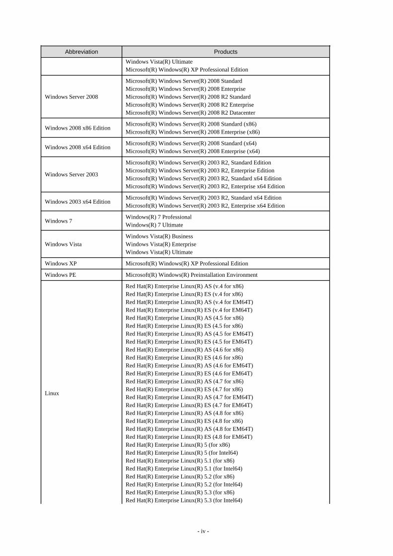
Abbreviations
The following abbreviations are used in this manual:
Abbreviation Products
Windows
Microsoft(R) Windows Server(R) 2008 StandardMicrosoft(R) Windows Server(R) 2008 EnterpriseMicrosoft(R) Windows Server(R) 2008 R2 StandardMicrosoft(R) Windows Server(R) 2008 R2 EnterpriseMicrosoft(R) Windows Server(R) 2008 R2 DatacenterMicrosoft(R) Windows Server(R) 2003 R2, Standard EditionMicrosoft(R) Windows Server(R) 2003 R2, Enterprise EditionMicrosoft(R) Windows Server(R) 2003 R2, Standard x64 EditionMicrosoft(R) Windows Server(R) 2003 R2, Enterprise x64 EditionWindows(R) 7 ProfessionalWindows(R) 7 UltimateWindows Vista(R) BusinessWindows Vista(R) Enterprise
- iii -
Abbreviation Products
Windows Vista(R) UltimateMicrosoft(R) Windows(R) XP Professional Edition
Windows Server 2008
Microsoft(R) Windows Server(R) 2008 StandardMicrosoft(R) Windows Server(R) 2008 EnterpriseMicrosoft(R) Windows Server(R) 2008 R2 StandardMicrosoft(R) Windows Server(R) 2008 R2 EnterpriseMicrosoft(R) Windows Server(R) 2008 R2 Datacenter
Windows 2008 x86 EditionMicrosoft(R) Windows Server(R) 2008 Standard (x86)Microsoft(R) Windows Server(R) 2008 Enterprise (x86)
Windows 2008 x64 EditionMicrosoft(R) Windows Server(R) 2008 Standard (x64)Microsoft(R) Windows Server(R) 2008 Enterprise (x64)
Windows Server 2003
Microsoft(R) Windows Server(R) 2003 R2, Standard EditionMicrosoft(R) Windows Server(R) 2003 R2, Enterprise EditionMicrosoft(R) Windows Server(R) 2003 R2, Standard x64 EditionMicrosoft(R) Windows Server(R) 2003 R2, Enterprise x64 Edition
Windows 2003 x64 EditionMicrosoft(R) Windows Server(R) 2003 R2, Standard x64 EditionMicrosoft(R) Windows Server(R) 2003 R2, Enterprise x64 Edition
Windows 7Windows(R) 7 ProfessionalWindows(R) 7 Ultimate
Windows VistaWindows Vista(R) BusinessWindows Vista(R) EnterpriseWindows Vista(R) Ultimate
Windows XP Microsoft(R) Windows(R) XP Professional Edition
Windows PE Microsoft(R) Windows(R) Preinstallation Environment
Linux
Red Hat(R) Enterprise Linux(R) AS (v.4 for x86)Red Hat(R) Enterprise Linux(R) ES (v.4 for x86)Red Hat(R) Enterprise Linux(R) AS (v.4 for EM64T)Red Hat(R) Enterprise Linux(R) ES (v.4 for EM64T)Red Hat(R) Enterprise Linux(R) AS (4.5 for x86)Red Hat(R) Enterprise Linux(R) ES (4.5 for x86)Red Hat(R) Enterprise Linux(R) AS (4.5 for EM64T)Red Hat(R) Enterprise Linux(R) ES (4.5 for EM64T)Red Hat(R) Enterprise Linux(R) AS (4.6 for x86)Red Hat(R) Enterprise Linux(R) ES (4.6 for x86)Red Hat(R) Enterprise Linux(R) AS (4.6 for EM64T)Red Hat(R) Enterprise Linux(R) ES (4.6 for EM64T)Red Hat(R) Enterprise Linux(R) AS (4.7 for x86)Red Hat(R) Enterprise Linux(R) ES (4.7 for x86)Red Hat(R) Enterprise Linux(R) AS (4.7 for EM64T)Red Hat(R) Enterprise Linux(R) ES (4.7 for EM64T)Red Hat(R) Enterprise Linux(R) AS (4.8 for x86)Red Hat(R) Enterprise Linux(R) ES (4.8 for x86)Red Hat(R) Enterprise Linux(R) AS (4.8 for EM64T)Red Hat(R) Enterprise Linux(R) ES (4.8 for EM64T)Red Hat(R) Enterprise Linux(R) 5 (for x86)Red Hat(R) Enterprise Linux(R) 5 (for Intel64)Red Hat(R) Enterprise Linux(R) 5.1 (for x86)Red Hat(R) Enterprise Linux(R) 5.1 (for Intel64)Red Hat(R) Enterprise Linux(R) 5.2 (for x86)Red Hat(R) Enterprise Linux(R) 5.2 (for Intel64)Red Hat(R) Enterprise Linux(R) 5.3 (for x86)Red Hat(R) Enterprise Linux(R) 5.3 (for Intel64)
- iv -

Abbreviation Products
Red Hat(R) Enterprise Linux(R) 5.4 (for x86)Red Hat(R) Enterprise Linux(R) 5.4 (for Intel64)Red Hat(R) Enterprise Linux(R) 5.5 (for x86)Red Hat(R) Enterprise Linux(R) 5.5 (for Intel64)Red Hat(R) Enterprise Linux(R) 5.6 (for x86)Red Hat(R) Enterprise Linux(R) 5.6 (for Intel64)SUSE(R) Linux Enterprise Server 10 Service Pack2 for x86SUSE(R) Linux Enterprise Server 10 Service Pack2 for EM64TSUSE(R) Linux Enterprise Server 10 Service Pack3 for x86SUSE(R) Linux Enterprise Server 10 Service Pack3 for EM64TSUSE(R) Linux Enterprise Server 11 for x86SUSE(R) Linux Enterprise Server 11 for EM64TSUSE(R) Linux Enterprise Server 11 Service Pack1 for x86SUSE(R) Linux Enterprise Server 11 Service Pack1 for EM64TOracle Enterprise Linux Release 5 Update 4 for x86 (32 Bit)Oracle Enterprise Linux Release 5 Update 4 for x86_64 (64 Bit)Oracle Enterprise Linux Release 5 Update 5 for x86 (32 Bit)Oracle Enterprise Linux Release 5 Update 5 for x86_64 (64 Bit)
Red Hat Enterprise Linux
Red Hat(R) Enterprise Linux(R) AS (v.4 for x86)Red Hat(R) Enterprise Linux(R) ES (v.4 for x86)Red Hat(R) Enterprise Linux(R) AS (v.4 for EM64T)Red Hat(R) Enterprise Linux(R) ES (v.4 for EM64T)Red Hat(R) Enterprise Linux(R) AS (4.5 for x86)Red Hat(R) Enterprise Linux(R) ES (4.5 for x86)Red Hat(R) Enterprise Linux(R) AS (4.5 for EM64T)Red Hat(R) Enterprise Linux(R) ES (4.5 for EM64T)Red Hat(R) Enterprise Linux(R) AS (4.6 for x86)Red Hat(R) Enterprise Linux(R) ES (4.6 for x86)Red Hat(R) Enterprise Linux(R) AS (4.6 for EM64T)Red Hat(R) Enterprise Linux(R) ES (4.6 for EM64T)Red Hat(R) Enterprise Linux(R) AS (4.7 for x86)Red Hat(R) Enterprise Linux(R) ES (4.7 for x86)Red Hat(R) Enterprise Linux(R) AS (4.7 for EM64T)Red Hat(R) Enterprise Linux(R) ES (4.7 for EM64T)Red Hat(R) Enterprise Linux(R) AS (4.8 for x86)Red Hat(R) Enterprise Linux(R) ES (4.8 for x86)Red Hat(R) Enterprise Linux(R) AS (4.8 for EM64T)Red Hat(R) Enterprise Linux(R) ES (4.8 for EM64T)Red Hat(R) Enterprise Linux(R) 5 (for x86)Red Hat(R) Enterprise Linux(R) 5 (for Intel64)Red Hat(R) Enterprise Linux(R) 5.1 (for x86)Red Hat(R) Enterprise Linux(R) 5.1 (for Intel64)Red Hat(R) Enterprise Linux(R) 5.2 (for x86)Red Hat(R) Enterprise Linux(R) 5.2 (for Intel64)Red Hat(R) Enterprise Linux(R) 5.3 (for x86)Red Hat(R) Enterprise Linux(R) 5.3 (for Intel64)Red Hat(R) Enterprise Linux(R) 5.4 (for x86)Red Hat(R) Enterprise Linux(R) 5.4 (for Intel64)Red Hat(R) Enterprise Linux(R) 5.5 (for x86)Red Hat(R) Enterprise Linux(R) 5.5 (for Intel64)Red Hat(R) Enterprise Linux(R) 5.6 (for x86)Red Hat(R) Enterprise Linux(R) 5.6 (for Intel64)
Red Hat Enterprise Linux 5
Red Hat(R) Enterprise Linux(R) 5 (for x86)Red Hat(R) Enterprise Linux(R) 5 (for Intel64)Red Hat(R) Enterprise Linux(R) 5.1 (for x86)Red Hat(R) Enterprise Linux(R) 5.1 (for Intel64)
- v -

Abbreviation Products
Red Hat(R) Enterprise Linux(R) 5.2 (for x86)Red Hat(R) Enterprise Linux(R) 5.2 (for Intel64)Red Hat(R) Enterprise Linux(R) 5.3 (for x86)Red Hat(R) Enterprise Linux(R) 5.3 (for Intel64)Red Hat(R) Enterprise Linux(R) 5.4 (for x86)Red Hat(R) Enterprise Linux(R) 5.4 (for Intel64)Red Hat(R) Enterprise Linux(R) 5.5 (for x86)Red Hat(R) Enterprise Linux(R) 5.5 (for Intel64)Red Hat(R) Enterprise Linux(R) 5.6 (for x86)Red Hat(R) Enterprise Linux(R) 5.6 (for Intel64)
SUSE Linux Enterprise Server
SUSE(R) Linux Enterprise Server 10 Service Pack2 for x86SUSE(R) Linux Enterprise Server 10 Service Pack2 for EM64TSUSE(R) Linux Enterprise Server 10 Service Pack3 for x86SUSE(R) Linux Enterprise Server 10 Service Pack3 for EM64TSUSE(R) Linux Enterprise Server 11 for x86SUSE(R) Linux Enterprise Server 11 for EM64TSUSE(R) Linux Enterprise Server 11 Service Pack1 for x86SUSE(R) Linux Enterprise Server 11 Service Pack1 for EM64T
Oracle Enterprise Linux
Oracle Enterprise Linux Release 5 Update 4 for x86 (32 Bit)Oracle Enterprise Linux Release 5 Update 4 for x86_64 (64 Bit)Oracle Enterprise Linux Release 5 Update 5 for x86 (32 Bit)Oracle Enterprise Linux Release 5 Update 5 for x86_64 (64 Bit)
Solaris Solaris(TM) 10 Operating System
VMwareVMware(R) Infrastructure 3VMware vSphere(TM) 4VMware vSphere(TM) 4.1
Xen
Citrix XenServer(TM) 5.5Citrix Essentials(TM) for XenServer 5.5, Enterprise EditionRed Hat(R) Enterprise Linux(R) 5.3 (for x86) Linux Virtual Machine FunctionRed Hat(R) Enterprise Linux(R) 5.3 (for Intel64) Linux Virtual Machine FunctionRed Hat(R) Enterprise Linux(R) 5.4 (for x86) Linux Virtual Machine FunctionRed Hat(R) Enterprise Linux(R) 5.4 (for Intel64) Linux Virtual Machine FunctionRed Hat(R) Enterprise Linux(R) 5.5 (for x86) Linux Virtual Machine FunctionRed Hat(R) Enterprise Linux(R) 5.5 (for Intel64) Linux Virtual Machine FunctionRed Hat(R) Enterprise Linux(R) 5.6 (for x86) Linux Virtual Machine FunctionRed Hat(R) Enterprise Linux(R) 5.6 (for Intel64) Linux Virtual Machine Function
VIOM ServerView Virtual-IO Manager
ServerView AgentServerView SNMP Agents for MS Windows (32bit-64bit)ServerView Agents LinuxServerView Agents VMware for VMware ESX Server
ExcelMicrosoft(R) Office Excel(R) 2007Microsoft(R) Office Excel(R) 2003Microsoft(R) Office Excel(R) 2002
Excel 2007 Microsoft(R) Office Excel(R) 2007
Excel 2003 Microsoft(R) Office Excel(R) 2003
Excel 2002 Microsoft(R) Office Excel(R) 2002
Resource Coordinator Systemwalker Resource Coordinator
Resource Coordinator VEServerView Resource Coordinator VESystemwalker Resource Coordinator Virtual server Edition
Resource Orchestrator ServerView Resource Orchestrator
- vi -

Export Administration Regulation Declaration
Documents produced by FUJITSU may contain technology controlled under the Foreign Exchange and Foreign Trade Control Law ofJapan. Documents which contain such technology should not be exported from Japan or transferred to non-residents of Japan without firstobtaining authorization from the Ministry of Economy, Trade and Industry of Japan in accordance with the above law.
Trademark Information
- BMC, BMC Software, and the BMC Software logo are trademarks or registered trademarks of BMC Software, Inc. in the UnitedStates and other countries.
- Citrix(R), Citrix XenServer(TM), Citrix Essentials(TM), and Citrix StorageLink(TM) are trademarks of Citrix Systems, Inc. and/orone of its subsidiaries, and may be registered in the United States Patent and Trademark Office and in other countries.
- Dell is a registered trademark of Dell Computer Corp.
- HP is a registered trademark of Hewlett-Packard Company.
- IBM is a registered trademark or trademark of International Business Machines Corporation in the U.S.
- Linux is a trademark or registered trademark of Linus Torvalds in the United States and other countries.
- Microsoft, Windows, Windows XP, Windows Server, Windows Vista, Windows 7, Excel, and Internet Explorer are either registeredtrademarks or trademarks of Microsoft Corporation in the United States and other countries.
- Oracle and Java are registered trademarks of Oracle and/or its affiliates in the United States and other countries.
- Oracle is a registered trademark of Oracle Corporation and/or its affiliates.
- Red Hat, RPM and all Red Hat-based trademarks and logos are trademarks or registered trademarks of Red Hat, Inc. in the UnitedStates and other countries.
- Spectrum is a trademark or registered trademark of Computer Associates International, Inc. and/or its subsidiaries.
- SUSE is a registered trademark of SUSE LINUX AG, a Novell business.
- VMware, the VMware "boxes" logo and design, Virtual SMP, and VMotion are trademarks or registered trademarks of VMware, Inc.in the United States and/or other jurisdictions.
- ServerView and Systemwalker are registered trademarks of FUJITSU LIMITED.
- All other brand and product names are trademarks or registered trademarks of their respective owners.
Notices
- The contents of this manual shall not be reproduced without express written permission from FUJITSU LIMITED.
- The contents of this manual are subject to change without notice.
Month/Year Issued, Edition Manual Code
November 2010, 6.0 J2X1-7459-06ENZ0(00)
February 2011, 6.1 J2X1-7459-06ENZ0(01)
March 2011, 6.2 J2X1-7459-06ENZ0(02)
July 2011, 6.3 J2X1-7459-06ENZ0(03)
August 2011, 6.4 J2X1-7459-06ENZ0(04)
Copyright FUJITSU LIMITED 2007-2011
- vii -

ContentsChapter 1 Overview..................................................................................................................................................................1
1.1 Features................................................................................................................................................................................................11.2 Function Overview..............................................................................................................................................................................4
1.2.1 Available Functions......................................................................................................................................................................41.2.2 Usage............................................................................................................................................................................................8
1.3 System Configuration..........................................................................................................................................................................91.4 Managed Resources...........................................................................................................................................................................10
Chapter 2 User Interface........................................................................................................................................................122.1 RC Console Layout............................................................................................................................................................................122.2 Menus.................................................................................................................................................................................................14
2.2.1 List of Menus..............................................................................................................................................................................142.2.2 Popup Menus..............................................................................................................................................................................17
2.3 Status Panel........................................................................................................................................................................................232.4 Tree Panel..........................................................................................................................................................................................242.5 Main Panel.........................................................................................................................................................................................26
2.5.1 [Resource List] Tab....................................................................................................................................................................262.5.2 [Resource Details] Tab...............................................................................................................................................................272.5.3 [Recovery Settings] Tab.............................................................................................................................................................362.5.4 [Image List] Tab.........................................................................................................................................................................362.5.5 [Network Map] Tab....................................................................................................................................................................37
2.6 Recent Operations..............................................................................................................................................................................372.7 Event Log...........................................................................................................................................................................................38
Chapter 3 System Design and Initial Setup............................................................................................................................403.1 Defining the Server Environment......................................................................................................................................................40
3.1.1 Chassis Settings (For blade server environments)......................................................................................................................403.1.2 Settings for Rack Mount or Tower Servers................................................................................................................................403.1.3 Settings for SPARC Enterprise (M3000/T Series) Servers........................................................................................................413.1.4 Chassis Settings (Settings for PRIMERGY Partition Models)...................................................................................................423.1.5 Chassis Settings (SPARC Enterprise M4000/M5000/M8000/M9000 servers)..........................................................................42
3.2 Defining the Network Environment..................................................................................................................................................433.2.1 Network Configuration...............................................................................................................................................................433.2.2 IP Addresses (Admin LAN).......................................................................................................................................................543.2.3 IP Addresses (iSCSI LAN).........................................................................................................................................................553.2.4 Public LAN Settings for Managed Servers.................................................................................................................................553.2.5 LAN Switch Settings..................................................................................................................................................................55
3.3 Defining the Storage Environment....................................................................................................................................................573.3.1 Storage Configuration.................................................................................................................................................................573.3.2 HBA and Storage Device Settings..............................................................................................................................................583.3.3 iSCSI Interface and Storage Device Settings (iSCSI)................................................................................................................603.3.4 Settings for ETERNUS SF Storage Cruiser Integration.............................................................................................................62
3.4 Defining the Power Monitoring Device Environment.......................................................................................................................623.4.1 Settings for the Power Monitoring Environment........................................................................................................................623.4.2 Power Monitoring Device Settings.............................................................................................................................................63
3.5 Configuring the Server Environment.................................................................................................................................................633.6 Configuring the Network Environment.............................................................................................................................................693.7 Configuring the Storage Environment...............................................................................................................................................703.8 Configuring the Power Monitoring Environment..............................................................................................................................71
Chapter 4 Installation..............................................................................................................................................................72
Chapter 5 Starting and Stopping............................................................................................................................................735.1 Manager.............................................................................................................................................................................................735.2 Agent..................................................................................................................................................................................................74
- viii -

5.3 RC Console........................................................................................................................................................................................76
Chapter 6 Setup.....................................................................................................................................................................786.1 Registering Resources........................................................................................................................................................................78
6.1.1 Registering VIOM Coordination................................................................................................................................................796.1.1.1 Registering VIOM Server Profiles......................................................................................................................................79
6.1.2 Registering Chassis.....................................................................................................................................................................796.1.2.1 Registering Chassis (For Blade Servers).............................................................................................................................796.1.2.2 Registering Chassis (For PRIMERGY Partition Models)...................................................................................................806.1.2.3 Registering SPARC Enterprise M4000/M5000/M8000/M9000 Servers............................................................................81
6.1.3 Registering Managed Servers.....................................................................................................................................................826.1.3.1 Registering Blade Servers and Partition Model Servers......................................................................................................836.1.3.2 Registering Rack Mount or Tower Servers.........................................................................................................................876.1.3.3 Registering SPARC Enterprise (M3000/T Series) Servers.................................................................................................91
6.1.4 Registering LAN Switches.........................................................................................................................................................946.1.4.1 Registering LAN Switch Blades..........................................................................................................................................946.1.4.2 Registering LAN Switches (Non-Blade Switches)..............................................................................................................95
6.1.5 Registering VM Management Software.....................................................................................................................................966.1.6 Registering Power Monitoring Devices......................................................................................................................................976.1.7 Registering Admin LAN Subnets [Windows]............................................................................................................................986.1.8 Registering ETERNUS SF Storage Cruiser..............................................................................................................................102
6.2 Configuring the Operating Environment of Managed Servers........................................................................................................1026.2.1 Configuring VLANs on LAN Switches....................................................................................................................................102
6.2.1.1 Configuring VLANs on external ports..............................................................................................................................1036.2.1.2 Configuring VLANs on internal ports...............................................................................................................................103
6.2.2 Configuring HBA address rename............................................................................................................................................1046.2.2.1 Settings for the HBA address rename setup service..........................................................................................................107
6.2.3 WWN Settings for ETERNUS SF Storage Cruiser Integration...............................................................................................1086.2.4 Software Installation and Agent Registration...........................................................................................................................1096.2.5 Cloning Image Deployment......................................................................................................................................................1126.2.6 Configuring Monitoring Information........................................................................................................................................112
6.3 Modifying Settings..........................................................................................................................................................................1136.3.1 Changing Admin Server Settings.............................................................................................................................................113
6.3.1.1 Changing Admin IP Addresses..........................................................................................................................................1136.3.1.2 Changing Port Numbers.....................................................................................................................................................1176.3.1.3 Changing the Maximum Number of System Image Versions...........................................................................................1206.3.1.4 Changing the Maximum Number of Cloning Image Versions..........................................................................................1206.3.1.5 Changing the Image Folder Location................................................................................................................................1216.3.1.6 Changing Admin LAN Subnets [Windows]......................................................................................................................1226.3.1.7 Changing the Password for the Resource Coordinator VE Database................................................................................123
6.3.2 Changing Chassis and Managed Servers Settings....................................................................................................................1246.3.2.1 Changing Chassis Names...................................................................................................................................................1246.3.2.2 Changing Server Names....................................................................................................................................................1246.3.2.3 Changing Admin IP Addresses..........................................................................................................................................1256.3.2.4 Changing SNMP Communities.........................................................................................................................................1266.3.2.5 Changing Server Management Unit Configuration Settings.............................................................................................1276.3.2.6 Changing Port Numbers.....................................................................................................................................................1286.3.2.7 Changing VM Host Login Account Information...............................................................................................................1296.3.2.8 Changing the VLAN Settings of LAN Switch Blades......................................................................................................1296.3.2.9 Changing HBA address rename Settings...........................................................................................................................1296.3.2.10 Changing Boot Options...................................................................................................................................................1296.3.2.11 Changing WWN Settings for ETERNUS SF Storage Cruiser Integration......................................................................130
6.3.3 Changing Settings for the HBA Address Rename Setup Service.............................................................................................1306.3.3.1 Changing the IP Address of the Admin Server..................................................................................................................1306.3.3.2 Changing the Port Number Used to Communicate with the Admin Server......................................................................1306.3.3.3 Changing the IP Address of the HBA Address Rename Server........................................................................................130
6.3.4 Changing VIOM Registration Settings.....................................................................................................................................131
- ix -

6.3.5 Changing LAN Switch Settings................................................................................................................................................1316.3.5.1 Changing LAN Switch Basic Settings...............................................................................................................................1316.3.5.2 Changing VLANs set on External LAN Switch Blade Ports............................................................................................1326.3.5.3 Re-discovering LAN Switches..........................................................................................................................................134
6.3.6 Changing VM Management Software Settings........................................................................................................................1346.3.7 Changing Power Monitoring Environment Settings.................................................................................................................135
6.3.7.1 Changing Environmental Data Settings.............................................................................................................................1356.3.7.2 Cancelling Collection Settings for Power Monitoring Environments...............................................................................1366.3.7.3 Changing Power Monitoring Devices................................................................................................................................136
6.3.8 Changing Monitoring Information Settings..............................................................................................................................1366.3.8.1 Changing Monitoring Information Settings.......................................................................................................................1366.3.8.2 Cancelling Monitoring Information Settings.....................................................................................................................137
6.4 Deleting Resources..........................................................................................................................................................................1376.4.1 Deleting Chassis.......................................................................................................................................................................1376.4.2 Deleting Managed Servers........................................................................................................................................................1376.4.3 Cancelling VIOM Integration...................................................................................................................................................1386.4.4 Deleting LAN Switches............................................................................................................................................................139
6.4.4.1 Deleting LAN Switch Blades............................................................................................................................................1396.4.4.2 Deleting LAN Switches (Non-Blade Switches)................................................................................................................139
6.4.5 Deleting VM Management Software........................................................................................................................................1396.4.6 Clearing the Power Monitoring Environment..........................................................................................................................140
6.4.6.1 Deleting Power Monitoring Devices.................................................................................................................................1406.4.7 Deleting Admin LAN Subnets [Windows]...............................................................................................................................1406.4.8 Unregistering ETERNUS SF Storage Cruiser..........................................................................................................................140
Chapter 7 Pre-configuration.................................................................................................................................................1417.1 Overview..........................................................................................................................................................................................1417.2 Importing the System Configuration File........................................................................................................................................1437.3 Exporting the System Configuration File........................................................................................................................................146
Chapter 8 Cloning [Windows/Linux].....................................................................................................................................1478.1 Overview..........................................................................................................................................................................................1478.2 Collecting a Cloning Image.............................................................................................................................................................1488.3 Deploying a Cloning Image.............................................................................................................................................................1538.4 Viewing a Cloning Image................................................................................................................................................................1578.5 Deleting a Cloning Image................................................................................................................................................................1588.6 Network Parameter Auto-Configuration for Cloning Images.........................................................................................................158
8.6.1 Operation Checks and Preparations..........................................................................................................................................1638.6.2 Maintenance..............................................................................................................................................................................1658.6.3 Clearing Settings.......................................................................................................................................................................1658.6.4 Modifying the Operating Environment.....................................................................................................................................165
Chapter 9 Server Switchover Settings..................................................................................................................................1679.1 Overview..........................................................................................................................................................................................1679.2 Configuration...................................................................................................................................................................................1699.3 Server Switchover Conditions.........................................................................................................................................................1729.4 Conditions Required for Auto-Recovery.........................................................................................................................................1739.5 Status Display..................................................................................................................................................................................1749.6 Server Switchover Settings..............................................................................................................................................................1749.7 Changing Server Switchover Settings.............................................................................................................................................1769.8 Cancelling Server Switchover Settings............................................................................................................................................177
Chapter 10 Saving Environment Settings.............................................................................................................................178
Appendix A Server Virtualization Products...........................................................................................................................179A.1 Supported Functions.......................................................................................................................................................................179A.2 Configuration Requirements...........................................................................................................................................................181A.3 Functional Differences between Products......................................................................................................................................185
- x -

Appendix B Connections between Server Network Interfaces and LAN Switch Ports.........................................................190
Appendix C Port List.............................................................................................................................................................192
Appendix D Format of CSV System Configuration Files......................................................................................................198D.1 Obtaining the System Configuration File (CSV Format)...............................................................................................................198D.2 File Format......................................................................................................................................................................................199D.3 Resource Definitions.......................................................................................................................................................................202D.4 Examples of CSV format................................................................................................................................................................218
Appendix E HTTPS Communications...................................................................................................................................222
Appendix F Maintenance Mode............................................................................................................................................227
Appendix G Notes on Installation.........................................................................................................................................228
Appendix H Coordination with Other Products.....................................................................................................................229H.1 Coordination with BMC BladeLogic Server Automation..............................................................................................................229H.2 Sending SNMP Traps.....................................................................................................................................................................232
H.2.1 SNMP Trap Settings Using CA Spectrum...............................................................................................................................234H.3 Single Sign-On................................................................................................................................................................................236
H.3.1 Defining the LDAP Server Environment.................................................................................................................................237H.3.2 Configuration...........................................................................................................................................................................237H.3.3 Modifying Settings...................................................................................................................................................................243
Appendix I WWN Allocation Order During HBA address rename Configuration..................................................................245
Appendix J Co-Existence with ServerView Deployment Manager.......................................................................................246J.1 Overview..........................................................................................................................................................................................246J.2 Restricted Functions.........................................................................................................................................................................247
Glossary...............................................................................................................................................................................248
- xi -

Chapter 1 OverviewThis chapter provides an overview of Resource Coordinator VE.
1.1 FeaturesResource Coordinator VE is a server management product which improves the usability and availability of server systems. It uniformlymanages physical servers as well as virtual servers created using server virtualization software (VMware and others).
The level of functionality provided by Resource Coordinator VE differs depending on the managed hardware environment. For details,refer to the corresponding "Note" in "1.2 Hardware Environment" of the "ServerView Resource Coordinator VE Installation Guide".
This section explains some of the features provided by Resource Coordinator VE.
- Integrated management of physical and virtual servers
Resource Coordinator VE provides an integrated management console for environments composed of physical and virtual servers. Ithelps administrators manage server configurations, monitor hardware failures, and determine the cause and impact of system errorsby automatically detecting and displaying the following information.
- Resource Coordinator VE provides a tree-based view of server hardware and their operating systems (physical OS, VM host, orVM guest).This enables easy confirmation and tracking of relationships between chassis, servers, and operating systems.
- Resource Coordinator VE monitors server hardware and displays icons representative of each server status.
Resource Coordinator VE also allows administrators to manage both physical and virtual servers in a uniform manner. Once registered,resources can be managed uniformly regardless of server models, types of server virtualization software, or differences betweenphysical and virtual servers.
- Auto-Recovery of failed servers
The function allows failed applications to automatically recover onto an available spare server by pre-allocating spare servers tomanaged servers.Depending on the server's boot method, one of the four following switchover methods can be used to recover applications on a spareserver:
- Backup and restore
This method is used in local boot environments where servers boot from an internal disk. Backing up the system disk of a primaryserver in advance allows automatic restoration and startup of the spare server when the primary server fails.
- HBA address rename
This method is used in SAN boot environments where servers start from boot disks located in SAN storage arrays. If the primaryserver fails, its World Wide Name (WWN) is inherited by the spare server, which then automatically starts up from the same SANdisk. This is made possible by the I/O virtualization (*1) capabilities of the HBA address rename function, which is able todynamically re-configure the WWN of an I/O adapter (HBA).
- VIOM server profile exchange method [Windows]
This method is used in SAN boot environments where servers start from boot disks located in SAN storage arrays or on a storagedevice connected to the LAN. If the primary server fails, the World Wide Name (WWN) and MAC address, boot configuration,and network configuration set in its server profile are inherited by the spare server, which then automatically starts up from thesame boot disk. This is made possible by the I/O virtualization (*1) capabilities of the HBA address rename function, which isable to dynamically re-configure the WWN of an I/O adapter (HBA).For details on server profiles, refer to the ServerView Virtual-IO Manager manual.
*1: Refer to "I/O virtualization".
- Storage affinity switchover
This method is used in SAN boot environments where servers start from boot disks located in SAN storage arrays. If the primaryserver fails, its switch zoning and host affinity configurations set in the fibre channel switch and the SAN storage using ESC areinherited by the WWN (World Wide Name) of the spare server, which then automatically starts up from the same SAN disk.
- 1 -
The following LAN switch settings can also be exchanged between primary and spare servers during server switchover. This featuresupports backup and restore, HBA address rename, or VIOM server profile exchange methods.
- VLAN
- Port groups (For PRIMERGY BX900/BX400 LAN switch blades operating in IBP mode)
Several servers can share one or more common spare servers, irrespective of the kind of servers used (physical or virtual), or theapplications that are running on them.Spare servers can also be shared between physical and virtual servers. This is done by combining the Auto-Recovery with the highavailability feature provided with the server virtualization software used.
Note that the Auto-Recovery function differs from clustering software (such as PRIMECLUSTER) in the following respect:
- Server failure detection
The Auto-Recovery function can detect hardware failures using server management software (such as ServerView Agents) andserver management devices (management blades, management boards, or remote management controllers). It cannot detect systemslowdowns.
- Automated server installation and setup
The following three features simplify server installation and setup:
- Deploying multiple servers via server cloning
Server cloning is a feature that distributes a cloning image (collected from the system disk of a reference server) to other physicalservers.When a cloning image is created, network-specific configuration such as host names and IP addresses are removed from thecloning image. This network-specific configuration is dynamically re-configured on the servers to which the cloning image isdistributed.This makes it possible to create duplicates of existing servers that will use the same operating system and software.
- Simplified server installation with I/O virtualization
I/O virtualization via HBA address rename (*1) allows storage devices to be set up independently and prior to the rest of the serverinstallation process. Servers can then be installed and set up without the involvement of storage administrators.
*1: Refer to "I/O virtualization".
- Multiple server installations using the pre-configuration feature
The pre-configuration feature can be used to configure all settings required for a Resource Coordinator VE setup in a systemconfiguration file, which can then be easily imported from the RC console.The system configuration file is in CSV format and can be edited easily even in environments where Resource Coordinator VEis not installed.
- Streamlined server maintenance
The following features help to identify which servers need to be replaced, and assist administrators with maintenance required afterreplacement of a server:
- Automatic maintenance LED activation on failed servers. (*1)
*1: Depending on the hardware being used, this feature may or may not be available. For details, refer to the corresponding "Note"in "1.2 Hardware Environment" of the "ServerView Resource Coordinator VE Installation Guide".
- In SAN boot environments, the I/O virtualization (*1) provided by either HBA address rename or VIOM makes it possible torestore a failed server's original WWN definition to the replacement server. Resource Coordinator VE is able to quickly reconnecta replaced server to its original volume(s) and start it up from the same operating system without accessing any storage device.Moreover, with the ability to automatically re-define MAC addresses, boot configuration, and network configuration using VIOM,it is no longer necessary to re-configure network devices or applications that depend on MAC address values.
*1: Refer to "I/O virtualization".
- In local boot environments, a system image backed up beforehand can be easily restored to the replaced server to simplify serverreplacement.
- 2 -

- Easy server monitoring
When managing PRIMERGY BX servers, BladeViewer can be used to easily check server statuses and perform other daily operations.In BladeViewer, server statuses are displayed in a format similar to the physical configuration of a blade server system, making servermanagement and operation more intuitive. BladeViewer provides the following features:
- Display of server blades' mount statuses.
- Provides an intuitive way to monitor and control multiple server blades' power statuses.
- Makes it easier to visualize which applications are running on each server blade. This helps to quickly identify any affectedapplications when a hardware fault occurs on a server blade.
- Easy network monitoring
For PRIMERGY BX servers, Resource Coordinator VE provides a Network Map function, which helps visualize and relate physicalnetworks (between servers and LAN switches) together with virtualized networks (from VLANs or virtual switches used in servervirtualization software). The Network Map provides the following features:
- Automatically detects and displays network connections (topology) and link statuses between heterogeneous network resources.
- Facilitates overall network consistency diagnostics and identification of the resources (physical and virtual) affected by a networkissue.
- Displays comprehensive content that can be used as a communication basis for server and network administrators, thus smoothingout coordination between the two parties.
- Monitoring of power consumption
By activating the power monitoring feature, it is possible to monitor trends in power consumption for resources equipped with powermonitoring capabilities, or resources connected to a registered power monitoring device (PDU or UPS). The power consumption dataregularly collected from the power monitoring environment can be output to a file in CSV format or a graph.
- Relocation of VM guests
By integrating with VM management software (such as VMware vCenter Server or others) and VM hosts (such as Citrix XenServeror others), Resource Coordinator VE provides the ability to migrate VM guests between physical servers directly from the RC console.When used with other Resource Coordinator VE functions, this enables the following:
- Regroup all VM guests to a subset of servers and shut down any unused server or chassis to reduce overall power consumption.
- When server maintenance becomes necessary, VM guests can be migrated to alternative servers and their applications kept aliveduring maintenance work.
I/O virtualization
I/O adapters (HBA) for servers are shipped with an assigned physical address that is unique across the world. This World Wide Name(WWN) is used by the storage network to identify servers. Until now, the WWN settings on storage networks needed to be updatedwhenever servers were added, replaced, or switched over. Resource Coordinator VE uses I/O virtualization technology that makes server-side I/O control possible. It does this by replacing physically-bound WWNs with virtual WWNs assigned to each server based on its rolein the system. Resource Coordinator VE can handle two different I/O virtualization technologies (HBA address rename and VIOM).With VIOM, the ability to re-define MAC addresses of network interfaces, boot configuration, and network configuration means that itis no longer necessary to re-configure network devices or applications that depend on Mac address values.
Note
- The "I/O virtualization option" is required when using HBA address rename.
- ServerView Virtual-IO Manager should be installed on the admin server when integrating Resource Coordinator VE with VIOM.
- The following functions are not available if ServerView Deployment Manager is used on the same subnet (admin LAN) as ResourceCoordinator VE. In such cases, it is recommended to use ServerView Deployment Manager and ServerView Virtual-IO Managerinstead.
- Cloning
- 3 -

- Backup and restore
- HBA address rename
- Server switchover based on HBA address rename, or backup and restore.
Refer to "Appendix J Co-Existence with ServerView Deployment Manager" for details.
1.2 Function OverviewThis section details the functions provided by Resource Coordinator VE.
1.2.1 Available FunctionsThis section details the functions provided by Resource Coordinator VE.
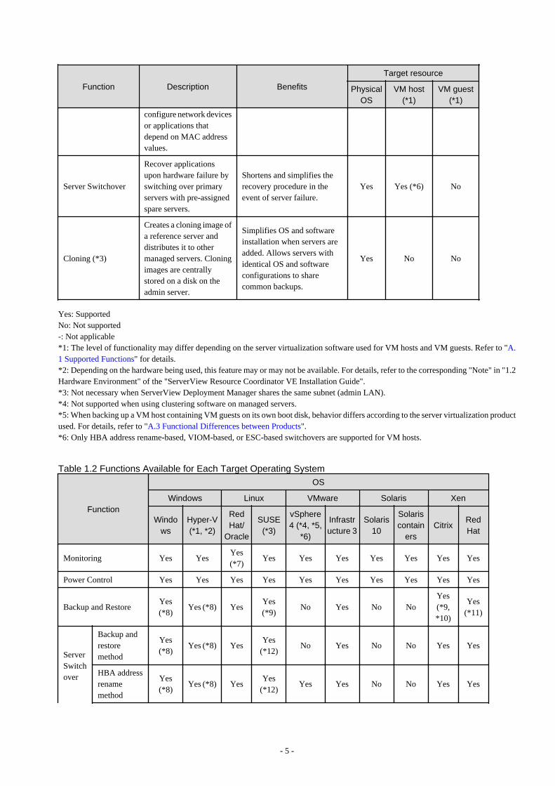
Table 1.1 Functions Available for Managed Servers
Function Description Benefits
Target resource
PhysicalOS
VM host(*1)
VM guest(*1)
Monitoring
Monitors resources, suchas servers, and displaystheir status (normal, error,etc.) on the RC console.
Helps identify the cause of afailure and determine itsimpact on servers, therebystreamlining hardwaremaintenance.
Yes(*2)
Yes (*2) Yes
Power ControlPowers on and offmanaged servers.
Enables remote control of amanaged server's power statewithout having direct accessto it. This simplifies periodicmaintenance tasks thatinvolve power controloperations.
Yes Yes Yes
Backup and restore(*3)
Creates system imagebackups of servers thatcan be easily restoredwhen needed. Systemimages are centrallystored on a disk on theadmin server.
Creating backups before anyconfiguration change, OS orsoftware installation, or patchapplication can drasticallyreduce the time to restore aserver to its original statewhen hardware or softwareproblems occur.
Yes(*4)
Yes (*4,*5)
No
HardwareMaintenance
Simplifies the re-configuration tasksrequired after replacementof a hardware part.In SAN environments, re-configuration of attachedstorage devices is nolonger required whenusing I/O virtualization.Moreover, with the abilityto re-define MACaddresses, bootconfiguration, andnetwork configurationusing VIOM, it is nolonger necessary to re-
Lightens the workloadassociated with hardwarereplacement and reduces therisk of operational errors.
Yes Yes -
- 4 -
Function Description Benefits
Target resource
PhysicalOS
VM host(*1)
VM guest(*1)
configure network devicesor applications thatdepend on MAC addressvalues.
Server Switchover
Recover applicationsupon hardware failure byswitching over primaryservers with pre-assignedspare servers.
Shortens and simplifies therecovery procedure in theevent of server failure.
Yes Yes (*6) No
Cloning (*3)
Creates a cloning image ofa reference server anddistributes it to othermanaged servers. Cloningimages are centrallystored on a disk on theadmin server.
Simplifies OS and softwareinstallation when servers areadded. Allows servers withidentical OS and softwareconfigurations to sharecommon backups.
Yes No No
Yes: SupportedNo: Not supported-: Not applicable*1: The level of functionality may differ depending on the server virtualization software used for VM hosts and VM guests. Refer to "A.1 Supported Functions" for details.*2: Depending on the hardware being used, this feature may or may not be available. For details, refer to the corresponding "Note" in "1.2Hardware Environment" of the "ServerView Resource Coordinator VE Installation Guide".*3: Not necessary when ServerView Deployment Manager shares the same subnet (admin LAN).*4: Not supported when using clustering software on managed servers.*5: When backing up a VM host containing VM guests on its own boot disk, behavior differs according to the server virtualization productused. For details, refer to "A.3 Functional Differences between Products".*6: Only HBA address rename-based, VIOM-based, or ESC-based switchovers are supported for VM hosts.
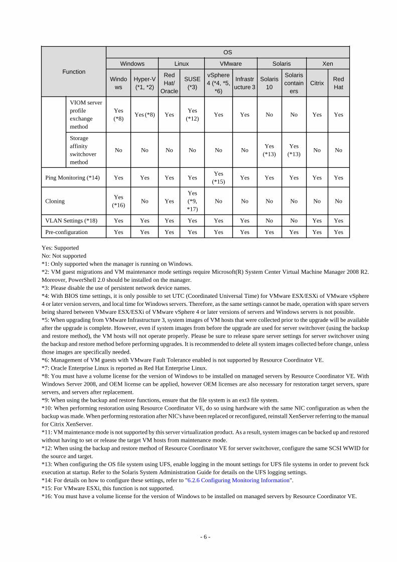
Table 1.2 Functions Available for Each Target Operating System
Function
OS
Windows Linux VMware Solaris Xen
Windows
Hyper-V(*1, *2)
RedHat/
Oracle
SUSE(*3)
vSphere4 (*4, *5,
*6)
Infrastructure 3
Solaris10
Solariscontain
ersCitrix
RedHat
Monitoring Yes YesYes(*7)
Yes Yes Yes Yes Yes Yes Yes
Power Control Yes Yes Yes Yes Yes Yes Yes Yes Yes Yes
Backup and RestoreYes(*8)
Yes (*8) YesYes(*9)
No Yes No NoYes(*9,*10)
Yes(*11)
ServerSwitchover
Backup andrestoremethod
Yes(*8)
Yes (*8) YesYes
(*12)No Yes No No Yes Yes
HBA addressrenamemethod
Yes(*8)
Yes (*8) YesYes
(*12)Yes Yes No No Yes Yes
- 5 -
Function
OS
Windows Linux VMware Solaris Xen
Windows
Hyper-V(*1, *2)
RedHat/
Oracle
SUSE(*3)
vSphere4 (*4, *5,
*6)
Infrastructure 3
Solaris10
Solariscontain
ersCitrix
RedHat
VIOM serverprofileexchangemethod
Yes(*8)
Yes (*8) YesYes
(*12)Yes Yes No No Yes Yes
Storageaffinityswitchovermethod
No No No No No NoYes
(*13)Yes
(*13)No No
Ping Monitoring (*14) Yes Yes Yes YesYes
(*15)Yes Yes Yes Yes Yes
CloningYes
(*16)No Yes
Yes(*9,*17)
No No No No No No
VLAN Settings (*18) Yes Yes Yes Yes Yes Yes No No Yes Yes
Pre-configuration Yes Yes Yes Yes Yes Yes Yes Yes Yes Yes
Yes: SupportedNo: Not supported*1: Only supported when the manager is running on Windows.*2: VM guest migrations and VM maintenance mode settings require Microsoft(R) System Center Virtual Machine Manager 2008 R2.Moreover, PowerShell 2.0 should be installed on the manager.*3: Please disable the use of persistent network device names.*4: With BIOS time settings, it is only possible to set UTC (Coordinated Universal Time) for VMware ESX/ESXi of VMware vSphere4 or later version servers, and local time for Windows servers. Therefore, as the same settings cannot be made, operation with spare serversbeing shared between VMware ESX/ESXi of VMware vSphere 4 or later versions of servers and Windows servers is not possible.*5: When upgrading from VMware Infrastructure 3, system images of VM hosts that were collected prior to the upgrade will be availableafter the upgrade is complete. However, even if system images from before the upgrade are used for server switchover (using the backupand restore method), the VM hosts will not operate properly. Please be sure to release spare server settings for server switchover usingthe backup and restore method before performing upgrades. It is recommended to delete all system images collected before change, unlessthose images are specifically needed.*6: Management of VM guests with VMware Fault Tolerance enabled is not supported by Resource Coordinator VE.*7: Oracle Enterprise Linux is reported as Red Hat Enterprise Linux.*8: You must have a volume license for the version of Windows to be installed on managed servers by Resource Coordinator VE. WithWindows Server 2008, and OEM license can be applied, however OEM licenses are also necessary for restoration target servers, spareservers, and servers after replacement.*9: When using the backup and restore functions, ensure that the file system is an ext3 file system.*10: When performing restoration using Resource Coordinator VE, do so using hardware with the same NIC configuration as when thebackup was made. When performing restoration after NIC's have been replaced or reconfigured, reinstall XenServer referring to the manualfor Citrix XenServer.*11: VM maintenance mode is not supported by this server virtualization product. As a result, system images can be backed up and restoredwithout having to set or release the target VM hosts from maintenance mode.*12: When using the backup and restore method of Resource Coordinator VE for server switchover, configure the same SCSI WWID forthe source and target.*13: When configuring the OS file system using UFS, enable logging in the mount settings for UFS file systems in order to prevent fsckexecution at startup. Refer to the Solaris System Administration Guide for details on the UFS logging settings.*14: For details on how to configure these settings, refer to "6.2.6 Configuring Monitoring Information".*15: For VMware ESXi, this function is not supported.*16: You must have a volume license for the version of Windows to be installed on managed servers by Resource Coordinator VE.
- 6 -

*17: Auto-configuration of network parameters cannot be used.*18: Only supported for blade models.
Table 1.3 Functions Available for Blade Chassis
Function Description Benefits
Power Control Powers on and off blade chassis.
Enables remote control of a chassis's powerstate without needing to connect to itsmanagement blade. This simplifies periodicmaintenance tasks that involve power controloperations.
Table 1.4 Functions Available for the Admin Server
Function Description Benefits
Pre-configuration
Systems made up of multiple servers can beeasily configured or modified using the pre-configuration function to import a pre-definedsystem configuration file.
Prevents setup mistakes by performing numeroussetup operations in a single action.System configuration files can be easily edited onmachines where Resource Coordinator VE is notinstalled.
Backup and RestoreBacks up or restores a Resource CoordinatorVE installation.
Performing backups after configuration changes aremade in Resource Coordinator VE enables promptrecovery of the admin server in case its internal datais damaged due to administration mistakes or otherproblems.
Table 1.5 Functions Available for LAN Switches
Function Description Benefits
LAN Switch Blades(*1) LAN
SwitchSwitchMode
IBPMode
MonitoringMonitors LAN switches anddisplays their statuses(normal or error) graphically.
Simplifies identification ofthe cause and impact of LANswitch failure on servers andspeeds up hardwaremaintenance.
Yes Yes Yes
Network Map
Helps visualize and relatephysical networks (betweenservers and LAN switchblades) together withvirtualized networks (fromVLANs or virtual switchesused in server virtualizationsoftware).
Automatically detects anddisplays network connections(topology) and link statusesfor different kinds ofresources (networkequipment or servervirtualization software).
Yes Yes Yes
VLAN Settings
Automates VLAN settings(port VLAN or taggedVLAN) on LAN switchesadjacent to servers.
Simplifies the VLANconfiguration of LANswitches when adding newservers. During automaticrecovery of a failed server,VLANs are automaticallyreconfigured to preserveconnectivity and avoidmanual network re-configurations.
Yes No No
- 7 -

Function Description Benefits
LAN Switch Blades(*1) LAN
SwitchSwitchMode
IBPMode
Port Group Setting
Automates port groupsettings on LAN switchblades in IBP mode duringserver switchover.
Reduces the number of stepsnecessary to recover thenetwork configuration of afailed server.
No Yes No
RestoreRestores a LAN switch to itsmost recent VLANconfiguration.
Restores the VLANconfiguration on a replacedLAN switch to theconfiguration that was activebefore replacement.
Yes No No
Yes: SupportedNo: Not supported*1: For PRIMERGY BX600 LAN switches please refer to the "switch mode" column.
Table 1.6 Functions Available for Power Monitoring Targets
Function Description Benefits
Power consumptionmonitoring
Monitors power consumption trends forresources equipped with powermonitoring capabilities, or resourcesconnected to power monitoring devices(PDU or UPS). Collects and outputspower consumption data over a givenperiod of time.
This function can be used to measure theeffectiveness of environmental policies andcost-saving initiatives on powerconsumption.
*1: For details on supported devices, refer to "1.2 Hardware Environment" of the "ServerView Resource Coordinator VE InstallationGuide".
Table 1.7 Functions Available for Virtual Machines
Function (*1) Description Benefits
Migration of VM guestsbetween servers
Migrates a VM guest from one physicalserver to another.
Facilitates optimization of VM guestdeployments according to server load orplanned maintenance.
VM maintenance modecontrol
Sets (or releases) VM hosts to (or from) aspecific state that allows safe servermaintenance.
VM hosts can be easily set out of and back intooperation.
VM Home Position setting,migration and clearing
Functions for setting, migrating, and clearingVM Home Positions.
Even if VM guests are migrated to differentlocations, they can be easily returned to theiroriginal locations.
*1: Available functions may vary according to the server virtualization software used. Refer to "A.1 Supported Functions" for details.
1.2.2 UsageResource Coordinator VE provides two different graphical views (*1), the RC console and BladeViewer, as well as a command lineinterface.
For details on the RC console, refer to "Chapter 2 User Interface".For details on BladeViewer, refer to "Chapter 3 BladeViewer" of the "ServerView Resource Coordinator VE Operation Guide".For details on the command line, refer to "Chapter 1 Overview" of the "ServerView Resource Coordinator VE Command Reference".
- 8 -

*1: When logging into Resource Coordinator VE for the first time, the RC console is displayed.
1.3 System ConfigurationThis section provides an example of a Resource Coordinator VE system configuration.
Figure 1.1 System Configuration Example
Admin Server
The admin server is a server used to manage several managed servers.The admin server operates in a Windows or Linux environment.The Resource Coordinator VE manager should be installed on the admin server. When using VIOM for I/O virtualization, ServerViewVirtual-IO Manager should also be installed on the admin server. When performing ESC-based switchover, ETERNUS SF StorageCruiser should also be installed on the admin server.The admin server can be made redundant by using clustering software.The admin client can operate on the same machine as the admin server.The Resource Coordinator VE agent cannot be installed on the admin server to monitor and manage the admin server itself.
Managed Servers
Managed servers are the servers used to run applications. They are managed by the admin server.There are the following 2 types of managed servers:
- Primary servers running Windows environments, Linux environments, Solaris environments, and server virtualization software
- Spare servers to be used in cases where a primary server fails
A Resource Coordinator VE agent should be installed on each managed server.Note that in server virtualization environments, the agent should only be installed on the VM host (it does not need to be installed onthe VM guests).
Admin Clients
Admin clients are terminals used to connect to the admin server, which can be used to monitor and control the configuration and statusof the entire system.Admin clients should run in a Windows environment.
- 9 -

A Web browser should be installed on admin clients.If a server virtualization software client is installed on an admin client, it can be launched directly from the RC console.
VM Management Server
A server on which VM management software (such as VMware vCenter Server and others) has been installed and is used to centrallymanage server virtualization software.Such a server can also be used as the admin server.
HBA address rename Server
This server is used to run the HBA address rename setup service.It is required when using HBA address rename for I/O virtualization (However, it is not required for VIOM-based I/O virtualization).This server takes care of configuring a managed server's WWN settings in place of the admin server if the admin server is unreachablewhen the managed server starts up.The HBA address rename server operates in a Windows or Linux environment.The HBA address rename setup service should be installed on this server for the HBA address rename function to operate properly.This server cannot serve as an admin server or as a managed server.This server must be powered on at all times to standby for an admin server failure or communication problems between a managedserver and the admin server.
Admin LAN
The admin LAN is the LAN used by the admin server to control managed servers.The admin LAN is set up separately from the public LAN used by applications on managed servers.Use of network redundancy software on the admin LAN enables redundancy for monitoring and power control functions.If admin LAN redundancy is performed, and backup or restore of a system image is used when there is a problem with part of theLAN, network redundancy can only be enabled by using the redundant line control function of PRIMECLUSTER GLS.
1.4 Managed ResourcesResource Coordinator VE can be used to manage the following resources:
Chassis
A chassis is an enclosure used to house server blades or PRIMERGY Partition Model servers or SPARC Enterprise M4000/M5000/M8000/M9000 servers which contain system boards.Monitoring of statuses, displaying properties, and controlling of power status (*1) can be performed. Resource Coordinator VE canalso automatically detect the servers contained in a chassis and register them as managed resources.
*1: Only possible with blade server chassis.
Server
This is a general term for any physical server. This term is used to distinguish physical servers from virtual servers that are createdusing server virtualization software such as VMware.Resource Coordinator VE can monitor server statuses, display their properties, and control their power states.It can also detect the physical OS's and VM hosts running on servers and register them as managed resources.
Physical OS
This refers to the operating system that operates directly on a physical server (instead of a virtual server).Resource Coordinator VE can monitor physical OS statuses and display their properties. It can also perform operations such as backup,HBA address rename, and server switchover.
VM host
This refers to the server virtualization software installed on a server that is used to run virtual machines.Resource Coordinator VE manages VM hosts in the same manner as physical OS's: it can monitor their statuses, display their properties,and perform operations such as HBA address rename and server switchover.When a VM host is registered, any VM guests on the VM host are automatically detected and displayed.
VM guest
This refers to the operating system running on top of a virtual machine.Resource Coordinator VE can monitor VM guest statuses, display their properties, and control their power states.
- 10 -

VM management software
A software product used to centrally manage an entire virtualization environment (e.g. VMware vCenter Server).VM management software can be integrated (registered) into Resource Coordinator VE to broaden the range of functions availablefor VM guests.
LAN switch
This term encompasses both the network switches that are mounted in a blade chassis (LAN switch blades), and the external LANswitches that are directly connected to them.Resource Coordinator VE can monitor LAN switch blade statuses, display their properties, and manage their VLAN configurations.LAN switch blades and external LAN switches can be displayed in a comprehensive Network Map.
Storage blade
This is a storage device mounted in a blade server chassis.It is automatically detected and displayed once its enclosing chassis has been registered. Its power state can be controlled in conjunctionwith the power state of the server it is connected to.
- 11 -

Chapter 2 User InterfaceResource Coordinator VE includes two graphical user interfaces: the RC console and BladeViewer.This chapter provides an overview of the RC console.
For details on how to open and close the RC console, refer to "5.3 RC Console".For details on BladeViewer, refer to "Chapter 3 BladeViewer" of the "ServerView Resource Coordinator VE Operation Guide".
2.1 RC Console LayoutThis section explains how the RC console is organized.
Figure 2.1 RC Console
Menus
Operations can be performed either from the menu bar or popup menus.
Status Panel
The Status Panel displays the status of managed servers.If a warning or error event occurs on a managed server, the status monitoring area starts to blink.
Tree Panel
By switching between tree types it is possible to select from the following 5 types of trees.
Server Resources
The resources below are shown in a tree view. A status icon is displayed over each resource's icon.
- 12 -

- Chassis
- Server
- Physical OS
- VM host
- VM guest
- LAN switch
Network Resources
The resources below are shown in a tree view. A status icon is displayed over each resource's icon.
- LAN switch (excluding LAN switch blades)
Power Monitoring Devices
The following power monitoring devices are shown in a tree view.
- PDU
- UPS
Management Software
The following management software which can be used in coordination with Resource Coordinator VE are shown in a tree view.A status icon is displayed over each resource's icon.
- Management software (vCenter Server)
- Management software (SCVMM)
- Management software (VIOM)
VLAN
Selecting a VLAN ID shows a list of resources on which this ID has been applied to.
- Chassis
- Server
- VM host
- VM guest
- LAN switch
- NIC
- LAN switch port
Main Panel
The Main Panel displays information on resources selected in the tree.
- [Resource List] tab
Displays information on resources related to the resource selected in the resource tree.
- [Resource Details] tab
Displays more detailed information on the resource selected in the tree, or on a resource that was double-clicked in the [ResourceList] tab.
- [Recovery Settings] tab
Displays information on the spare servers assigned to the resource selected in the resource tree.
- [Image List] tab
Displays system and cloning image information.
- 13 -
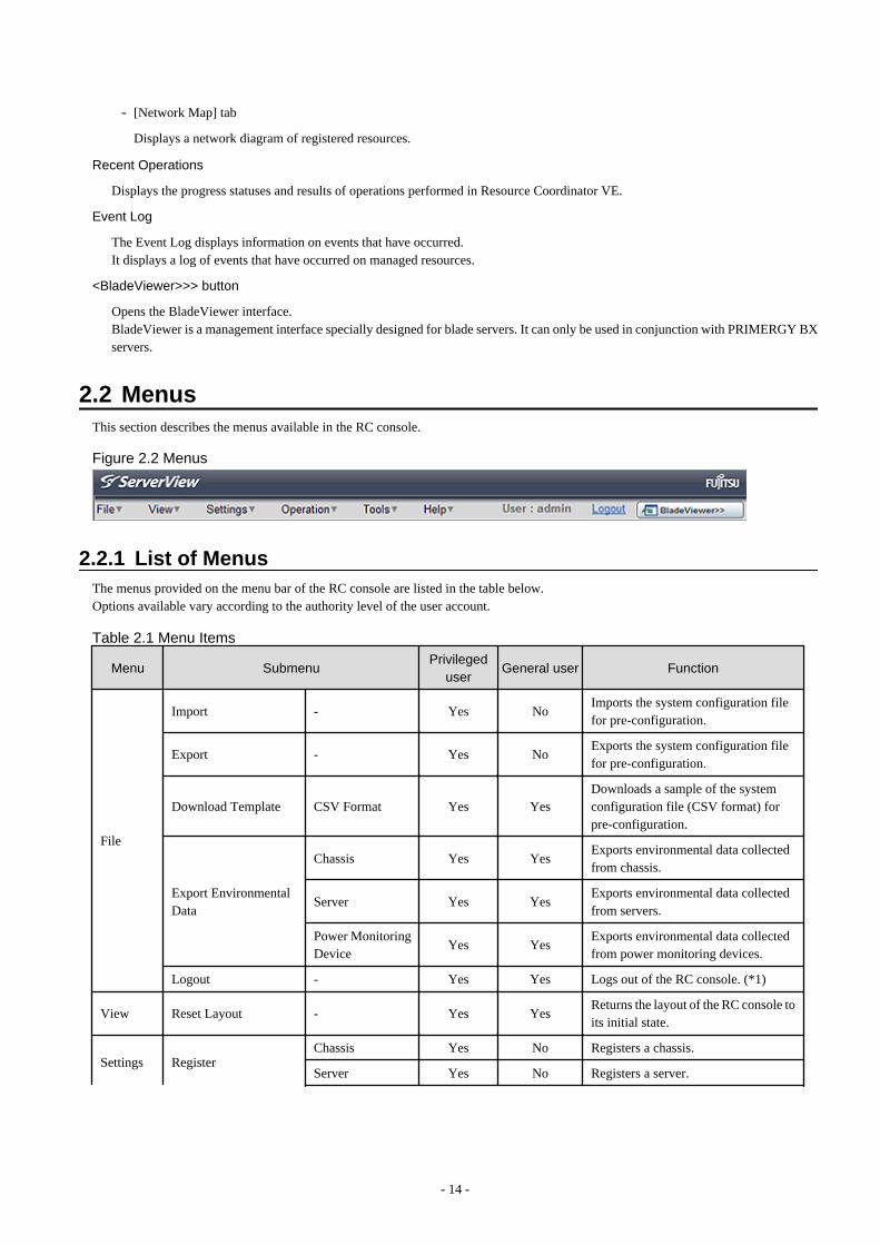
- [Network Map] tab
Displays a network diagram of registered resources.
Recent Operations
Displays the progress statuses and results of operations performed in Resource Coordinator VE.
Event Log
The Event Log displays information on events that have occurred.It displays a log of events that have occurred on managed resources.
<BladeViewer>>> button
Opens the BladeViewer interface.BladeViewer is a management interface specially designed for blade servers. It can only be used in conjunction with PRIMERGY BXservers.
2.2 MenusThis section describes the menus available in the RC console.
Figure 2.2 Menus
2.2.1 List of MenusThe menus provided on the menu bar of the RC console are listed in the table below.Options available vary according to the authority level of the user account.
Table 2.1 Menu Items
Menu SubmenuPrivileged
userGeneral user Function
File
Import - Yes NoImports the system configuration filefor pre-configuration.
Export - Yes NoExports the system configuration filefor pre-configuration.
Download Template CSV Format Yes YesDownloads a sample of the systemconfiguration file (CSV format) forpre-configuration.
Export EnvironmentalData
Chassis Yes YesExports environmental data collectedfrom chassis.
Server Yes YesExports environmental data collectedfrom servers.
Power MonitoringDevice
Yes YesExports environmental data collectedfrom power monitoring devices.
Logout - Yes Yes Logs out of the RC console. (*1)
View Reset Layout - Yes YesReturns the layout of the RC console toits initial state.
Settings RegisterChassis Yes No Registers a chassis.
Server Yes No Registers a server.
- 14 -

Menu SubmenuPrivileged
userGeneral user Function
SPARCEnterprise(M3000/T Series)
Yes NoRegisters a SPARC Enterprise(M3000/T series) server.
SPARCEnterprise(Partition Model)
Yes NoRegisters SPARC Enterprise M4000/M5000/M8000/M9000 servers.
PRIMERGYPartition Model
Yes NoRegisters a PRIMERGY PartitionModel.
LAN Switch Yes No Registers a LAN switch.
Agent Yes No Registers an agent.
Power MonitoringDevice
Yes No Registers a power monitoring device.
ManagementSoftware (vCenterServer)
Yes NoRegisters VM management software(VMware vCenter Server).
ManagementSoftware(SCVMM)
Yes NoRegisters VM management software(System Center Virtual MachineManager).
ManagementSoftware (VIOM)
Yes NoRegisters VM management software(VIOM).
Delete - Yes No Deletes a resource.
Modify (*2)
RegistrationSettings
Yes NoModifies a resource's registrationsettings.
HBA AddressRename Settings(*3)
Yes NoModifies the HBA address renamesettings of a server.
Network Settings(*4, *5)
Yes NoModifies the network settings of aLAN switch.
Spare ServerSettings (*6)
Yes No Modifies a server's recovery settings.
MonitoringSettings
Yes NoModifies the monitoring informationfor a server.
WWN Settings(*7)
Yes NoModifies the WWN settings for aserver.
VM Host LoginAccount
Yes NoModifies the registered login accountused to communicate with the VMhost.
User Accounts (*8) - Yes YesAdds, changes, and deletes useraccounts.
Admin LAN Subnet - Yes Yes (*9)Performs viewing, registration,changing or deletion of the admin LANsubnet information.
Operation
Update - Yes Yes Updates a resource.
Power
ON Yes No Powers on a server.
OFF Yes NoPowers off a server after shutting downits operating system.
- 15 -

Menu SubmenuPrivileged
userGeneral user Function
OFF (Forced) Yes NoPowers off a server without shuttingdown its operating system.
Reboot Yes NoReboots a server after shutting down itsoperating system.
Reboot (Forced) Yes NoReboots a server without shuttingdown its operating system.
LED (*4)ON Yes No Turns the maintenance LED on.
OFF Yes No Turns the maintenance LED off.
Spare Server (*2, *6)
Switchover Yes NoSwitches over a server with one of itsspare servers.
Failback Yes NoSwitches back a server to its pre-switchover state.
Takeover Yes NoAccepts a switched over configurationas final (without switching back to theoriginal configuration).
Hardware Maintenance
Re-configure Yes NoDetects and re-configures theproperties of a replaced server.
Restore LANSwitch (*10)
Yes No Restores a LAN switch configuration.
Maintenance Mode(*2)
Set Yes No Places a server into maintenance mode.
Release Yes No Sets a server to active mode.
Backup/Restore (*2)Backup Yes No Backs up a system image from a server.
Restore Yes No Restores a system image to a server.
Cloning (*2, *11)Collect Yes No Collects a cloning image from a server.
Deploy Yes No Deploys a cloning image to a server.
Migrate VM Guest - Yes NoMigrates a VM guest to a different VMhost.
VM Home Position
Settings Yes No Sets VM Home Position.
Clear Yes No Clears VM Home Position.
Back to Home Yes NoMigrates a VM guest to VM HomePosition
Tools
Topology
Discover LANswitches
Yes NoDiscovers LAN switches within theadmin LAN.
Detect physicallinks
Yes NoAcquires physical link data fromregistered LAN switches.
Options - Yes Yes (*12)Modifies client and environmental datasettings.
Environmental DataGraph
- Yes Yes Displays environmental data graphs.
HelpManual - Yes Yes Displays product manuals.
About - Yes Yes Displays product version information.
*1: If multiple RC console or BladeViewer sessions exist, the login sessions may be terminated.*2: Cannot be selected for a VM guest.
- 16 -

*3: Cannot be selected for PRIMERGY or SPARC Enterprise Partition Models.*4: Available only for PRIMERGY BX servers.*5: Cannot be set for PRIMERGY BX900/BX400 LAN switch blades operating in IBP mode.*6: Cannot be selected for PRIMERGY Partition Models. *7: Can only be selected for SPARC Enterprise servers.*8: Cannot be selected when logging in using Single Sign-On.*9: Only the admin LAN subnet information can be displayed with general user privileges.*10: Not available for PRIMERGY BX900/BX400 LAN switch blades operating in IBP mode.*11: Cannot be selected for a VM host.*12: General users cannot change environmental data settings.
2.2.2 Popup MenusRight-clicking an object displayed in the resource tree or in the [Image List] tab displays a popup menu with a list of options available forthat object.The tables below detail the popup menus provided for each object.Available menus vary according to user account privileges.
Table 2.2 Popup Menus Available for the "Server Resources" Tree Node
Popup menu Privilegeduser
Generaluser
FunctionMenu Submenu
Register
Chassis Yes No Registers a chassis.
Server Yes No Registers a server.
SPARC Enterprise(M3000/T Series)
Yes NoRegisters a SPARC Enterprise (M3000/Tseries) server.
SPARC Enterprise(Partition Model)
Yes NoRegisters the chassis of a SPARC EnterpriseM4000/M5000/M8000/M9000 server.
PRIMERGY PartitionModel
Yes NoRegisters a PRIMERGY Partition Modelchassis.
Export
Environmental Data(Chassis)
Yes YesExports environmental data collected fromchassis.
Environmental Data(Servers)
Yes YesExports environmental data collected fromservers.
Table 2.3 Popup Menus Available for Chassis
Popup menu Privilegeduser
Generaluser
FunctionMenu Submenu
Delete - Yes No Deletes a chassis.
Update - Yes Yes Updates a chassis.
Modify Registration Settings Yes No Modifies a chassis' registration settings.
External ManagementSoftware
- Yes Yes Opens a Management Blade's Web interface.
Export (*1) Environmental Data Yes YesExports environmental data collected fromchassis.
*1: This option is only available for chassis equipped with power monitoring capabilities.
- 17 -

Table 2.4 Popup Menus Available for ServersPopup menu Privileged
userGeneral
userFunction
Menu Submenu
RegisterServer (*1) Yes No Registers a server.
Agent Yes No Registers an agent.
Delete - Yes No Deletes a server.
Update - Yes Yes Updates a server.
Modify
Registration Settings Yes No Modifies a server's registration settings.
HBA Address RenameSettings (*2)
Yes NoModifies the HBA address rename settings of aserver.
Network Settings (*3,*4)
Yes No Modifies the network settings of a server.
Spare Server Settings(*2)
Yes No Modifies a server's recovery settings.
Maintenance ModeSet Yes No Places a server into maintenance mode.
Release Yes No Sets a server to active mode.
Power
ON Yes No Powers on a server.
OFF Yes NoPowers off a server after shutting down itsoperating system.
OFF (Forced) Yes NoPowers off a server without shutting down itsoperating system.
Reboot Yes NoReboots a server after shutting down itsoperating system.
Reboot (Forced) Yes NoReboots a server without shutting down itsoperating system.
LED (*3)ON Yes No Turns the maintenance LED on.
OFF Yes No Turns the maintenance LED off.
HardwareMaintenance
Re-configure Yes NoDetects and re-configures the properties of areplaced server.
Backup/Restore Restore Yes No Restores a system image to a server.
Cloning Deploy Yes No Deploys a cloning image to a server.
External ManagementSoftware (*5)
- Yes Yes Opens external server management software.
Export (*6) Environmental Data Yes YesExports environmental data collected fromservers.
*1: Available only for PRIMERGY BX servers and PRIMERGY Partition Model servers.*2: Available only for VM hosts when using PRIMERGY Partition Models.*3: Available only for PRIMERGY BX servers.*4: Can only be selected for VM guests.*5: Available only when PRIMERGY servers, PRIMERGY Partition Model servers and SPARC Enterprise M series servers are registered.*6: This option is only available for chassis equipped with power monitoring capabilities.
Table 2.5 Popup Menus Available for SPARC Enterprise Servers
Popup menu Privilegeduser
Generaluser
FunctionMenu Submenu
Register Server (*1) Yes No Registers a server.
- 18 -

Popup menu Privilegeduser
Generaluser
FunctionMenu Submenu
Agent Yes No Registers an agent.
Delete - Yes No Deletes a SPARC Enterprise server.
Update - Yes Yes Updates a SPARC Enterprise server.
Modify
Registration Settings Yes NoModifies a SPARC Enterprise server'sregistration settings.
WWN Settings Yes No Modifies the WWN settings for a server.
Spare Server Settings Yes No Modifies a server's recovery settings.
Maintenance ModeSet Yes No Places a server into maintenance mode.
Release Yes No Sets a server to active mode.
Power
ON Yes No Powers on a SPARC Enterprise server.
OFF Yes NoPowers off a SPARC Enterprise server aftershutting down its operating system.
OFF (Forced) Yes NoPowers off a SPARC Enterprise server withoutshutting down its operating system.
Reboot Yes NoReboots a SPARC Enterprise server aftershutting down its operating system.
Reboot (Forced) Yes NoReboots a SPARC Enterprise server withoutshutting down its operating system.
External ManagementSoftware
- Yes YesOpens external server management software forSPARC Enterprise servers.
Export (*2) Environmental Data Yes YesExports environmental data collected fromservers.
*1: Can only be selected for SPARC Enterprise M4000/M5000/M8000/M9000 servers.*2: This option is only available for chassis equipped with power monitoring capabilities.
Table 2.6 Popup Menus Available for Physical OS's [Windows/Linux], VM Hosts and VM Guests
Popup menu Privilegeduser
Generaluser
FunctionMenu Submenu
Delete (*1) - Yes No Deletes a physical OS or VM host.
Update - Yes Yes Updates a physical OS, VM host or VM guest.
Modify (*1, *2)
HBA Address RenameSettings (*3, *4)
Yes NoModifies the HBA address rename settings of aserver.
Network Settings (*4,*5, *6)
Yes No Modifies the network settings of a server.
Spare Server Settings(*3, *4)
Yes No Modifies a server's recovery settings.
Monitoring Settings Yes NoModifies the monitoring information for aserver.
VM Host LoginAccount (*7)
Yes NoModifies the registered login account used tocommunicate with the VM host.
Power
ON Yes No Powers on a server.
OFF Yes NoPowers off a server after shutting down itsoperating system.
- 19 -

Popup menu Privilegeduser
Generaluser
FunctionMenu Submenu
OFF (Forced) Yes NoPowers off a server without shutting down itsoperating system.
Reboot Yes NoReboots a server after shutting down itsoperating system.
Reboot (Forced) Yes NoReboots a server without shutting down itsoperating system.
Spare Server (*1, *3,*4)
Switchover Yes NoSwitches over a server with one of its spareservers.
Failback Yes NoSwitches back a server to its pre-switchoverstate.
Takeover Yes NoAccepts a switched over configuration as final(without switching back to the originalconfiguration).
Maintenance Mode(*1, *4)
Configuration Yes No Places a server into maintenance mode.
Release Yes No Sets a server to active mode.
Backup/Restore (*1,*4)
Backup Yes No Backs up a system image from a server.
Restore Yes No Restores a system image to a server.
Cloning (*1, *8)Collect Yes No Collects a cloning image from a server.
Deploy Yes No Deploys a cloning image to a server.
VM Home Position(*1, *7)
Settings Yes No Sets VM Home Position.
Clear Yes No Clears VM Home Position.
Back to Home Yes No Migrates a VM guest to VM Home Position
External ManagementSoftware (*1, *9)
- Yes Yes Opens external server management software.
VM ManagementConsole (*4, *7, *10)
- Yes YesOpens the VM management console installedon the client machine.
Migrate VM Guest(*11)
- Yes No Migrates a VM guest to a different VM host.
*1: Cannot be selected for a VM guest.*2: Available only for VM hosts when using PRIMERGY Partition Models.*3: Cannot be selected for PRIMERGY Partition Models.*4: This option may or may not be available according to the server virtualization software used. Refer to "A.1 Supported Functions" fordetails.*5: Available only for PRIMERGY BX servers.*6: Cannot be set for PRIMERGY BX900/BX400 LAN switch blades operating in IBP mode.*7: This menu is not available for a physical OS.*8: Cannot be selected for a VM host.*9: Available only when PRIMERGY servers, PRIMERGY Partition Model servers and SPARC Enterprise M series servers are registered.*10: To use this feature, a VM management console must be installed and the admin client must be configured properly.After installing the VM management console, select this menu item and follow the instructions shown in the displayed dialog.*11: Can only be selected for VM guests.
- 20 -

Table 2.7 Popup Menus Available for Physical OS's [Solaris]Popup menu Privileged
userGeneral
userFunction
Menu Submenu
Delete - Yes No Deletes a SPARC Enterprise server.
Update - Yes Yes Updates a SPARC Enterprise server.
Modify
Spare Server Settings Yes No Modifies a server's recovery settings.
Monitoring Settings Yes NoModifies a SPARC Enterprise server'smonitoring settings.
Power
ON Yes No Powers on a SPARC Enterprise server.
OFF Yes NoPowers off a SPARC Enterprise server aftershutting down its operating system.
OFF (Forced) Yes NoPowers off a SPARC Enterprise server withoutshutting down its operating system.
Reboot Yes NoReboots a SPARC Enterprise server aftershutting down its operating system.
Reboot (Forced) Yes NoReboots a SPARC Enterprise server withoutshutting down its operating system.
Spare Server
Switchover Yes NoSwitches over a server with one of its spareservers.
Failback Yes NoSwitches back a server to its pre-switchoverstate.
Takeover Yes NoAccepts a switched over configuration as final(without switching back to the originalconfiguration).
Maintenance ModeSet Yes No Places a server into maintenance mode.
Release Yes No Sets a server to active mode.
External ManagementSoftware
- Yes YesOpens external server management software forSPARC Enterprise servers.
Table 2.8 Popup Menus Available for LAN Switches
Popup menu Privilegeduser
Generaluser
FunctionMenu Submenu
Register LAN Switch Yes No Registers a LAN switch.
Delete - Yes No Deletes a LAN switch.
Update - Yes Yes Updates a LAN switch.
Modify
Registration Settings Yes No Modifies a LAN switch's registration settings.
Network Settings (*1) Yes NoModifies VLAN settings of a LAN switch'sexternal ports.
Restore (*1) - Yes No Restores a LAN switch configuration.
External ManagementSoftware
- Yes Yes Opens a LAN switch's Web interface.
*1: Not available for PRIMERGY BX900/BX400 LAN switch blades operating in IBP mode.
- 21 -

Table 2.9 Popup Menus Available for System ImagesPopup menu Privileged
userGeneral
userFunction
Menu Submenu
Restore - Yes No Restores a system image to a server.
Delete - Yes No Deletes a system image.
Table 2.10 Popup Menus Available for Cloning Images
Popup menu Privilegeduser
Generaluser
FunctionMenu Submenu
Deploy - Yes No Deploys a cloning image to a server.
Delete - Yes No Deletes a cloning image.
Note
If ServerView Deployment Manager is used on the admin LAN, the popup menu for cloning images cannot be used.
Table 2.11 Popup Menus Available for the "Network Resources" Tree Node
Popup menu Privilegeduser
Generaluser
FunctionMenu Submenu
Topology
Discover LANswitches
Yes NoDiscovers LAN switches within the adminLAN.
Detect physical links Yes NoAcquires physical link data from registeredLAN switches.
Table 2.12 Popup Menus Available for the "Power Monitoring Devices" Tree Node
Popup menu Privilegeduser
Generaluser
FunctionMenu Submenu
RegisterPower MonitoringDevice
Yes No Registers a power monitoring device.
Export Environmental Data Yes Yes Exports environmental data.
Table 2.13 Popup Menus Available for Power Monitoring Devices
Popup menu Privilegeduser
Generaluser
FunctionMenu Submenu
Delete - Yes No Deletes a power monitoring device.
Update (*1) - Yes Yes Updates a power monitoring device.
Modify Registration Settings Yes NoModifies a power monitoring device'sregistration settings.
HardwareMaintenance
Re-configure Yes NoDetects and re-configures the properties of areplaced power monitoring device.
Export Environmental Data Yes Yes Exports environmental data.
*1: Unlike other resources, the properties of a power monitoring devices are not automatically updated. Use this option to update themmanually when necessary.
- 22 -

Table 2.14 Popup Menus Available for Management SoftwarePopup menu Privileged
userGeneral
userFunction
Menu Submenu
Register
Management Software(vCenter Server)
Yes NoRegisters VM management software (VMwarevCenter Server).
Management Software(SCVMM)
Yes NoRegisters VM management software (SystemCenter Virtual Machine Manager).
Management Software(VIOM)
Yes No Registers VM management software (VIOM).
Table 2.15 Popup Menus Available for Management Software (vCenter Server/SCVMM/VIOM)
Popup menu Privilegeduser
Generaluser
FunctionMenu Submenu
Delete - Yes No Deletes management software
Update - Yes Yes Updates management software information.
Modify Registration Settings Yes NoModifies registration settings for managementsoftware.
2.3 Status PanelThis section explains the different statuses that are displayed in the RC console.
Figure 2.3 Status Panel
Status Monitoring Area
The Event Log monitors a history of events that have occurred on managed resources.Based on detected events, the status monitoring area will change color and blink. Clicking the status monitoring area will stop theblinking.The following table details the different statuses and their associated corrective actions.
Table 2.16 Monitor Status List
Monitoring statusBackground
colorDetails Corrective action
Monitoring events GreyThis indicates a normal state.No warning or error-level events haveoccurred on the displayed resources.
No action is necessary.
Warning eventdetected
YellowThis indicates a warning state.A warning-level event has occurred onone or more of the displayed resources.
Click the status monitoring area tostop the blinking and fix the cause ofthe problem.
Error event detected RedThis indicates an error state.An error-level event has occurred onone or more of the displayed resources.
Click the status monitoring area tostop the blinking and fix the cause ofthe problem.
- 23 -

Resource Status Area
This area displays the number of registered servers experiencing each status.The resource status area lights up when there is at least one server in either "Error" or "Warning" status.Clicking a lit up status area will display a list of resources with that status in the [Resource List] tab. Double-click a displayed resourceto switch to its [Resource Details] tab and open either its external management software or the Management Blade's Web interface toinvestigate the problem.
2.4 Tree PanelThis section describes the trees used in the RC console.
Figure 2.4 Tree Panel
In the tree panel, clicking the area on the upper-left enables selection and display of the following 5 types of tree: server resources, networkresources, power monitoring devices, management software, and VLAN.
Server Resources
Chassis, servers, physical OS's, VM hosts, VM guests, and LAN switches managed in Resource Coordinator VE are displayed in atree view. Resources are primarily displayed in registration order. However, for server blades within a common chassis, the order bywhich Resource Coordinator VE detects blades takes precedence.Resources displayed in the resource tree are represented by an icon and their resource name. For details on the icons used to indicatedifferent resources, refer to "5.2 Resource Status" of the "ServerView Resource Coordinator VE Operation Guide".For a non-registered resource, one of the following registration states is displayed at the end of the resource's name.
Table 2.17 Resource Registration States
[Unregistered] The resource was automatically detected, but has not been registered yet
[Registering] The resource is being registered
[Admin Server] This server is the admin server itself
If a label was set for a resource (in BladeViewer), that label is displayed after the resource name.
Display format
resource_name(label)
- 24 -

Clicking a resource in the resource tree displays information related to that resource in the Main Panel. Right-clicking a resourcedisplays a list of available operations in a popup menu.For details on popup menus, refer to "2.2.2 Popup Menus".
When a problem occurs on a resource, it is represented by an icon shown on top of the resource icon.For details on status icons, refer to "5.2 Resource Status" of the "ServerView Resource Coordinator VE Operation Guide".Clicking a resource icon will show information related to that resource in the Main Panel. Use this information to investigate theproblem.For details on the information displayed in the Main Panel, refer to "2.5 Main Panel".
Network Resources
External LAN switches (those other than LAN switch blades) managed in Resource Coordinator VE are shown in a tree view. Resourcesare sorted and displayed by name in alphabetical order.
Network resources displayed in the resource tree are represented by an icon and their resource name.For details on the icons used to indicate different resources, refer to "5.2 Resource Status" of the "ServerView Resource CoordinatorVE Operation Guide".
For a non-registered resource, one of the following registration states is displayed at the end of the resource's name.
Table 2.18 Resource Registration States
[Unregistered] The resource was automatically detected, but has not been registered yet
[Registering] The resource is being registered
When a problem occurs on a resource, it is represented by an icon shown on top of the resource icon.For details on status icons, refer to "5.2 Resource Status" of the "ServerView Resource Coordinator VE Operation Guide".
Clicking a resource icon will show information related to that resource in the Main Panel. Use this information to investigate theproblem.
Power Monitoring Devices
The power monitoring devices (PDU or UPS) used by Resource Coordinator VE to monitor power consumption are displayed in atree view.For details on icons used to represent power monitoring devices, refer to "5.2 Resource Status" of the "ServerView ResourceCoordinator VE Operation Guide".Clicking a power monitoring device displayed in the resource tree will display its attributes in the Main Panel. Right-clicking a powermonitoring device will display a list of available operations in a popup menu.For details on the information displayed in the Main Panel, refer to "2.2.2 Popup Menus" for details on popup menus, and "2.5 MainPanel".
Management Software
Management software (vCenter Server, SCVMM, and VIOM) used in coordination with Resource Coordinator VE is displayed in atree view.For details on the icons used to indicate management software, refer to "5.2 Resource Status" of the "ServerView Resource CoordinatorVE Operation Guide".
Clicking a management software on the tree displays information related to it in the Main Panel. Right-clicking a power monitoringdevice will display a list of available operations in a popup menu.For details on the information displayed in the Main Panel, refer to "2.2.2 Popup Menus" for details on popup menus, and "2.5 MainPanel".
VLAN
Resources for which VLAN IDs have been applied are displayed in a tree view. The following resource types are displayed.
- Server
- 25 -
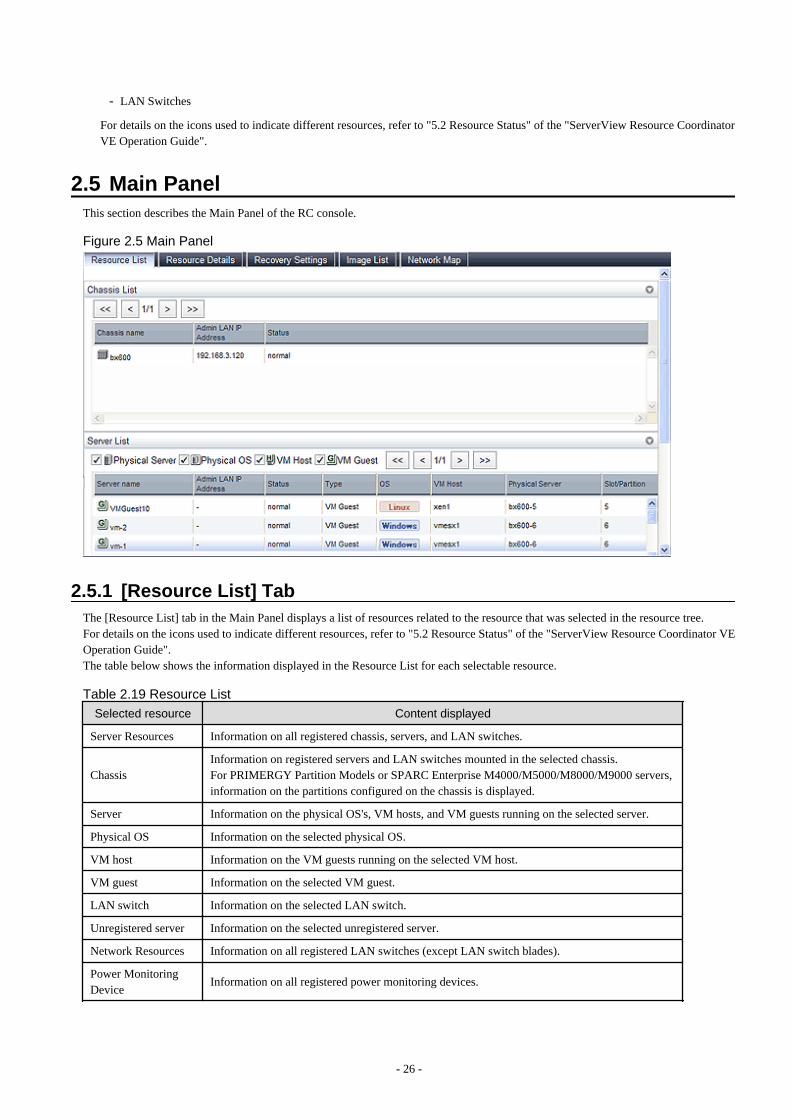
- LAN Switches
For details on the icons used to indicate different resources, refer to "5.2 Resource Status" of the "ServerView Resource CoordinatorVE Operation Guide".
2.5 Main PanelThis section describes the Main Panel of the RC console.
Figure 2.5 Main Panel
2.5.1 [Resource List] TabThe [Resource List] tab in the Main Panel displays a list of resources related to the resource that was selected in the resource tree.For details on the icons used to indicate different resources, refer to "5.2 Resource Status" of the "ServerView Resource Coordinator VEOperation Guide".The table below shows the information displayed in the Resource List for each selectable resource.
Table 2.19 Resource List
Selected resource Content displayed
Server Resources Information on all registered chassis, servers, and LAN switches.
ChassisInformation on registered servers and LAN switches mounted in the selected chassis.For PRIMERGY Partition Models or SPARC Enterprise M4000/M5000/M8000/M9000 servers,information on the partitions configured on the chassis is displayed.
Server Information on the physical OS's, VM hosts, and VM guests running on the selected server.
Physical OS Information on the selected physical OS.
VM host Information on the VM guests running on the selected VM host.
VM guest Information on the selected VM guest.
LAN switch Information on the selected LAN switch.
Unregistered server Information on the selected unregistered server.
Network Resources Information on all registered LAN switches (except LAN switch blades).
Power MonitoringDevice
Information on all registered power monitoring devices.
- 26 -
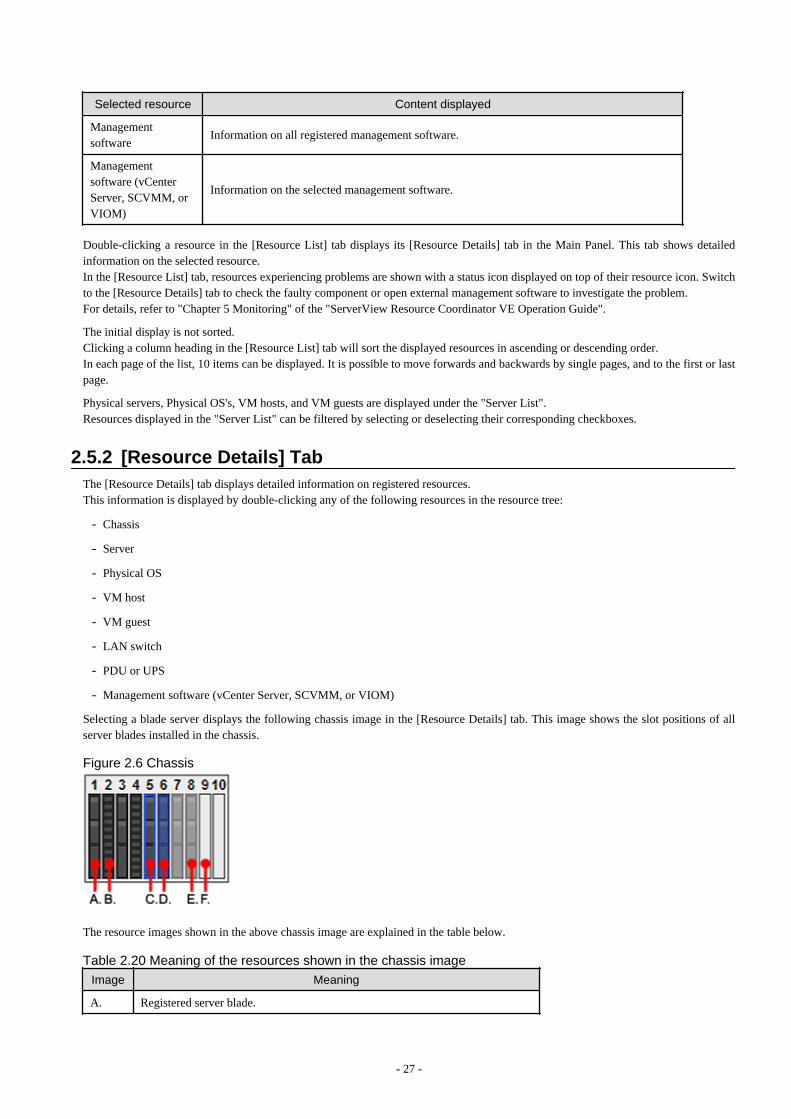
Selected resource Content displayed
Managementsoftware
Information on all registered management software.
Managementsoftware (vCenterServer, SCVMM, orVIOM)
Information on the selected management software.
Double-clicking a resource in the [Resource List] tab displays its [Resource Details] tab in the Main Panel. This tab shows detailedinformation on the selected resource.In the [Resource List] tab, resources experiencing problems are shown with a status icon displayed on top of their resource icon. Switchto the [Resource Details] tab to check the faulty component or open external management software to investigate the problem.For details, refer to "Chapter 5 Monitoring" of the "ServerView Resource Coordinator VE Operation Guide".
The initial display is not sorted.Clicking a column heading in the [Resource List] tab will sort the displayed resources in ascending or descending order.In each page of the list, 10 items can be displayed. It is possible to move forwards and backwards by single pages, and to the first or lastpage.
Physical servers, Physical OS's, VM hosts, and VM guests are displayed under the "Server List".Resources displayed in the "Server List" can be filtered by selecting or deselecting their corresponding checkboxes.
2.5.2 [Resource Details] TabThe [Resource Details] tab displays detailed information on registered resources.This information is displayed by double-clicking any of the following resources in the resource tree:
- Chassis
- Server
- Physical OS
- VM host
- VM guest
- LAN switch
- PDU or UPS
- Management software (vCenter Server, SCVMM, or VIOM)
Selecting a blade server displays the following chassis image in the [Resource Details] tab. This image shows the slot positions of allserver blades installed in the chassis.
Figure 2.6 Chassis
The resource images shown in the above chassis image are explained in the table below.
Table 2.20 Meaning of the resources shown in the chassis image
Image Meaning
A. Registered server blade.
- 27 -
Image Meaning
B. Detected storage blade.
C. Currently displayed server blade.
D. Server blade selected within the chassis image.
E. Server blade that has not been registered yet.
F. Empty slot.
Attributes of Displayed Resources
The [Resource Details] tab displays different attributes for each resource, as described below.
- Chassis Attributes
Table 2.21 General Area
Item Content displayed
Chassis name Name used to identify a chassis.
Model name Chassis model name.
Admin LAN (IP address) Chassis management IP address.
Status Chassis status.
Server blades (*1) Number of server blades mounted in the chassis.
Partition count (*2) Number of partitions mounted.
LAN Switch blades (*1) Number of LAN switches mounted in the chassis.
*1: Displayed only when the chassis of a blade server is selected.*2: Displayed only when the chassis of a PRIMERGY Partition Model or SPARC Enterprise M4000/M5000/M8000/M9000 serversis selected.
See
Refer to "5.2 Resource Status" of the "ServerView Resource Coordinator VE Operation Guide" for details on resource statuses.
Table 2.22 Hardware Details Area
Item Content displayed
Launch Management Blade Web UI (*1) Link to the management blade's Web interface.
Launch XSCF Web UI (*2) Link to the remote management controller (XSCF) Web UI.
*1: Not displayed for SPARC Enterprise M4000/M5000/M8000/M9000 servers.*2: Displayed only for SPARC Enterprise M4000/M5000/M8000/M9000 servers.
The following is displayed only when the chassis of a PRIMERGY Partition Model or SPARC Enterprise M4000/M5000/M8000/M9000 servers is selected.
Table 2.23 Partition Configuration
Item Content displayed
Partition ID The number of a partition.
Partition name The name used to identify a partition.
SB The ID of the system board used to configure a partition.
- 28 -

Item Content displayed
IOB The ID of the IO board used to configure a partition.
GSPB The ID of the GSPB used to configure a partition.
Reserved SB The ID of the Reserved SB assigned to a partition.
LSB (*1) The partition logical system board (LSB) number.
XSB (*1) The partition eXtended System Board (XSB) number.
*1: Displayed only for SPARC Enterprise M4000/M5000/M8000/M9000 servers.
- Server Attributes
Table 2.24 General Area
Item Content displayed
Physical server name Name used to identify a server.
Model name Server model name. (*1)
Product name Server product name. (*2)
Status Server status.
Slot (*3) A slot number representing the mounted location.
Partition (*4) The number of a partition.
Maintenance Mode (*5)Operational status of a server.Either "active" or "maintenance" will be displayed.
LED status (*3) Illumination status of the maintenance LED.
Admin LAN (MAC address) (*5) MAC address of the NIC used for the admin LAN.
CPU type (*6) Type of CPU.
CPU clock speed (*6) CPU clock speed (frequency).
Memory capacity (*6, *7) Total capacity of server memory.
HBAAR LAN (MAC address) (*5, *8) MAC address used for the HBA address rename setup service.
Hardware Maintenance Mode (*9) Server status.
Boot option The settings of the boot option specified when registering servers.
*1: The model name displayed for powered-on, registered servers is obtained from ServerView Operations Manager. For other servers,no model name is displayed.*2: For PRIMERGY BX servers, the product name obtained from the management blade is displayed. For other servers, the modelname is displayed.*3: Displayed only for PRIMERGY BX servers.*4: Displayed only when the chassis of a PRIMERGY Partition Model or SPARC Enterprise M4000/M5000/M8000/M9000 serversis selected.*5: Not displayed when SPARC Enterprise servers are selected.*6: This attribute is displayed as "-" for servers other than PRIMERGY BX servers or SPARC Enterprise M servers.*7: For SPARC Enterprise M4000/M5000/M8000/M9000 servers, this is displayed only when the server is powered on.*8: Displayed only for servers other than PRIMERGY BX servers.*9: Displayed only when a PRIMERGY Partition Model server is selected.
See
- Refer to the Management Blade's manual for details on management blades' product names.
- Refer to the ServerView Operation Manager manual for details on the server models displayed and obtained from ServerViewOperation Manager.
- 29 -

- Refer to "5.2 Resource Status" of the "ServerView Resource Coordinator VE Operation Guide" for details on resource statuses.
Table 2.25 Hardware Details Area
Item Content displayed
Server management software (*1) Link to the web interface of external server management software.
Remote Management Controller IPaddress (*2)
IP address of the remote management controller.
I/O Virtualization Management Software(*3)
Link to the web interface of I/O Virtualization management software.
VIOM server profile (*4) The assigned VIOM server profile name is displayed.
*1: Displayed only when PRIMERGY servers, PRIMERGY Partition Model servers, or SPARC Enterprise servers are selected.*2: Displayed only for servers other than PRIMERGY BX servers.*3: Displayed only if coordinated up with external I/O virtualization management software.*4: Displayed only if managed by VIOM and a server profile has been set.
Table 2.26 Network Properties Area
Item Content displayed
Physical ConnectionsList of physical connections between the server's network interfaces and LANswitches ports.
When a column heading in the list is clicked, the color of the selected column will change and the resources can be sorted in eitherascending or descending order.
Table 2.27 Hardware Maintenance Area
Item Content displayed
NIC Summary (*1) Shows the IP addresses associated with each MAC address.
*1: For servers other than PRIMERGY BX servers and PRIMERGY Partition Model servers, only admin LAN information isdisplayed. For SPARC Enterprise servers, only the IP address is displayed.
Information
The IP address displayed is the one set within the server's operating system.For network interfaces that were made redundant using BACS software, the information set in BACS (within the operating system)is displayed.
Displayed only when the server of a PRIMERGY Partition Model or SPARC Enterprise M4000/M5000/M8000/M9000 servers isselected.
Table 2.28 Partition Configuration
Item Content displayed
Partition name The name used to identify a partition.
SB The ID of the system board used to configure a partition.
IOB The ID of the IO board used to configure a partition.
GSPB The ID of the GSPB used to configure a partition.
Reserved SB The ID of the Reserved SB assigned to a partition.
LSB (*1) The partition logical system board (LSB) number.
XSB (*1) The partition eXtended System Board (XSB) number.
- 30 -

*1: Displayed only for SPARC Enterprise M4000/M5000/M8000/M9000 servers.
- Physical OS, VM Host and VM Guest Attributes
Table 2.29 General Area
Item Content displayed
Server name Name used to identify a physical OS, VM host, or VM guest.
Admin LAN (IP address) (*1) IP address on the admin LAN.
Status Status of the physical OS, VM host, or VM guest.
TypeType of the OS running on the server.One of "physical OS", "VM host", and "VM guest" will be displayed.
OS Name of the operating system running on the server.
Physical server name (*1)Name of the server on which the physical OS, VM host, or VM guest isoperating.
*1: Not displayed for VM guests.
See
Refer to "5.2 Resource Status" of the "ServerView Resource Coordinator VE Operation Guide" for details on resource statuses.
The following information is displayed only for VM Hosts.
Table 2.30 VM Host Information Area
Item Content displayed
VM type Type of VM.
VM software name Name of the VM software used.
VM software VL Version level of the VM software used.
Number of VM guests Number of VM guests.
VM management software Link to the VM management console.
VM guests List of hosted VM guests.
VM Home Positions (VM Guests)List of the VM guests with the selected VM host set as their VM HomePosition.
The following information is displayed only for VM guests.
Table 2.31 VM Guest Information Area
Item Content displayed
VM type Type of VM.
VM host name Name of the VM host on which the VM guest is stored.
VM name VM name.
VM management software Link to the VM management console.
The following information is not displayed for VM guests.
- 31 -

Table 2.32 Hardware Details AreaItem Content displayed
Server management software (*1) Link to the web interface of external server management software.
Remote Management Controller IPaddress (*2)
IP address of the remote management controller.
*1: Displayed only when PRIMERGY servers, PRIMERGY Partition Model servers, or SPARC Enterprise servers are selected.*2: Displayed only for servers other than PRIMERGY BX servers.
The following information is not displayed for VM guests or SPARC Enterprise servers.
Table 2.33 Latest System Image Area
Item Content displayed
Version Latest version of the system image.
Backup date Date and time of the most recent system image backup.
Comments Comments describing the system image.
The following information is not displayed for VM guests.
Table 2.34 Spare Server Settings Area
Item Content displayed
Primary serverName of the physical server that will be switched over during a serverswitchover.
Active server Name of the currently active physical server.
Server switchover method Method used to perform server switchover.
Server boot method System disk boot type.
Automatic server recovery Flag indicating whether automatic server recovery is enabled or not.
Network switchoverFlag indicating whether or not to switch over network settings during a serverswitchover.
Force spare server to power off duringswitchover
Sets whether the spare server is turned off forcibly, when switching over tothe spare server.
Switch over to spare server running VMguests
Sets whether the server is switched to a VM host on which a VM guest exists.
Spare server Names of assigned spare servers.
The following information is not displayed for VM guests or SPARC Enterprise servers.
Table 2.35 HBA Address Rename Settings Area
Item Content displayed
WWNN The WWNN set on the HBA.
WWPN 1 First WWPN set on the HBA. (*1)
WWPN 2 Second WWPN set on the HBA. (*1)
*1: The WWPN should be set to the I/O address of each HBA (in descending order).Therefore, for rack mount or tower servers, the order may not correspond with port number order described for the HBA.
- 32 -

The following information is not displayed for VM guests.
Table 2.36 Network Properties Area (VLAN)
Item Content displayed
Index Mounted position (index) of each network interface on the server.
Port VLAN ID (*1)Port VLAN IDs set on the LAN switch ports connected to each networkinterface.
Tagged VLAN ID (*1)Tagged VLAN IDs set on the LAN switch ports connected to each networkinterface.
*1: Displays only "(IBP)" when connected to a PRIMERGY BX 900/BX400 LAN switch blade operating in IBP mode.
Table 2.37 Port Groups Area (IBP)
Item Content displayed
NIC Index Mounted position (index) of each network interface on the server.
Group (*1)Names of the port groups set on the LAN switch ports connected to eachnetwork interface (for LAN switch blades operating in IBP mode).
*1: Displays only "-" under the following conditions.
- The corresponding LAN switch is not registered.
- The corresponding LAN switch is not operating in IBP mode.
- The corresponding LAN switch port has not been assigned to a port group.
Table 2.38 Monitoring Information
Item Content displayed
Timeout(sec) Time-out value for ping monitoring.
Recovery method Recovery is performed when an error is detected.
Number of reboots Number of times reboot is performed during recovery.
The following information is not displayed for VM guests or servers other than SPARC Enterprise servers.
Table 2.39 WWN Settings Area
Item Content displayed
WWPN of port n (n:1-8) (*1) WWPN for port n.
Target CA WWPN WWPN for the CA connected to port n.
Target CA AffinityGroup AffinityGroup for the CA connected to port n.
*1: Values set by users are reflected in WWPN.
- LAN Switch Attributes
Table 2.40 General Area
Item Content displayed
LAN switch name Name used to identify a LAN switch.
System Name (sysName) System name set on the LAN switch.
IP address IP address on the admin LAN.
Device name (Product name) Device name of the LAN switch.
Model Model name of the LAN switch.
- 33 -

Item Content displayed
VendorLAN switch vendor.This is not displayed for LAN switch blades.
Serial number Serial number of the LAN switch.
Firmware version Firmware version of the LAN switch.
Device status Status of the LAN switch.
SlotSlot number (mounted position) of the LAN switch. This is only displayed forLAN switch blades, in other cases "-" is displayed.
See
Refer to "5.2 Resource Status" of the "ServerView Resource Coordinator VE Operation Guide" for details on resource statuses.
Table 2.41 Hardware Details Area
Item Content displayed
Launch Switch Blade Web UI Link to the LAN switch's Web interface.
Note
If no Web interface is available for the selected LAN switch, the following message is displayed: "There is no information to display".Refer to the LAN switch manual to confirm whether or not a Web interface is provided.
Table 2.42 Port Properties Area
Item Content displayed
Port Number Selected LAN switch port.
Port Name Name assigned to the selected port.
Link StatusLink status of the selected port.Either "up" or "down" will be displayed.
Speed/DuplexModeSpeed and duplex mode of the selected port.One of "10M/H", "10M/F", "100M/H", "100M/F", "1G/F", and "10G/F" willbe displayed.
Table 2.43 Link Data Area
Item Content displayed
Resource Name (left side) Name of the selected LAN switch.
I/F (left side) Ports of the selected LAN switch.
I/F (right side)Network interface (of a server resource) connected to the LAN switch portshown on the left side.
Resource Name (right side) Name of the server resource connected to the LAN switch.
The following attributes are not displayed for PRIMERGY BX900/BX400 LAN switch blades operating in IBP mode.
Table 2.44 VLAN Area
Item Content displayed
VLAN ID List of VLAN IDs set in the selected LAN switch.
- 34 -

Item Content displayed
Untagged Port(s) (*1) List of ports set with a port VLAN ID.
Tagged Port(s) (*1) List of ports set with tagged VLAN ID(s).
*1: Logical ports with link aggregation will not be displayed.
The following attributes are only displayed for PRIMERGY BX900/BX400 LAN switch blades operating in IBP mode.
Table 2.45 Port Groups Area
Item Content displayed
Group Name of a port group configured on the selected LAN switch blade.
TypeType of the displayed port group.One of "Port Group", "VLAN Port Group", "Service LAN" and "ServiceVLAN" will be displayed.
VLAN ID VLAN ID assigned to this port group.
Downlink Ports Name of the downlink ports assigned to this port group.
UplinkSet Name of the UplinkSet assigned to this port group.
Table 2.46 UplinkSet Area
Item Content displayed
UplinkSetName of an UplinkSet (set of external ports) configured on the selected LANswitch blade.
Active Port Name of the active port within the port backup configuration of this UplinkSet.
Backup PortsName of the backup port within the port backup configuration of thisUplinkSet.
Link StateDisplays whether link state functionality was enabled or not for thisUplinkSet.
Port BackupDisplays whether port backup functionality was enabled or not for thisUplinkSet.
IGMP Snooping Displays whether or not IGMP snooping is enabled for this UplinkSet.
LACP Displays whether or not LACP is enabled for this UplinkSet.
- Power monitoring devices (PDU or UPS) attributes
Table 2.47 General Area
Item Content displayed
Device name Name used to identify a power monitoring device.
Admin LAN (IP address) IP address on the admin LAN.
Device type Device type (PDU or UPS).
Model Model name of the device.
Comments Comments describing the device.
Table 2.48 Hardware Details Area
Item Content displayed
Serial number Serial number of the device.
Voltage Voltage supplied to the device.
- 35 -

Item Content displayed
Hardware version (*1) Hardware version of the PDU.
Firmware version Firmware version of the device (PDU or UPS).
Date of manufacture Manufacturing date of the device.
Outlets (*1) Number of outlets provided by the PDU.
Intended orientation (*1) Intended orientation (horizontal or vertical) of the PDU.
*1: Not displayed for the UPS.
- Management Server Attributes
Table 2.49 General Area
Item Content displayed
Management software name Name used to identify the management software.
TypeManagement software type.One of "vCenter Server", "SCVMM", and "VIOM" will be displayed.
IP address IP address of the management software.
Status Management software status.
Management software Link to the web interface of the management software.
2.5.3 [Recovery Settings] TabThe [Recovery Settings] tab displays a list of spare servers assigned to the resource selected in the server resource tree.The table below shows the information displayed in the [Recovery Settings] tab.
Table 2.50 [Recovery Settings] tab
Item Content displayed
Server Name Name used to identify a physical OS or VM host.
Admin LAN IP Address IP address on the admin LAN.
Primary Server Name of the currently active server.
Switchover State Current switchover state.
Spare Server Name(s) of the server(s) assigned as spare server(s).
The switchover state is indicated by an arrow shown next to the currently active Primary Server. The messages "Switchover in progress","Failback in progress", or "Takeover in progress" are displayed respectively during a server switchover, failback, or takeover process.If more than one spare server has been set, the first server listed is the one that is currently running.
Clicking a column heading in this list will change the color of the selected column and sort the displayed recovery settings in eitherascending or descending order.In each page of the list, 10 items can be displayed. It is possible to move forwards and backwards by single pages, and to the first or lastpage.
2.5.4 [Image List] TabThe [Image List] tab displays information regarding available images.Those lists can be used to manage both system images and cloning images.
The following two tables list the items that are displayed in System Image List and Cloning Image List.
Table 2.51 System Image List Area
Item Content displayed
Server Name Name used to identify a physical OS or VM host.
- 36 -

Item Content displayed
Version Version of the system image.
Backup Date Date and time of the system image backup.
Comments Comments describing the system image.
Table 2.52 Cloning Image List Area
Item Content displayed
Cloning Image Name Name used to identify a cloning image.
Version Version of the cloning image.
Collection Date Collection date and time of the cloning image.
OS Name of the operating system stored in the cloning image.
Comments Comments describing the cloning image.
Right-clicking a resource in the list displays a list of available operations in a popup menu.Refer to "2.2.2 Popup Menus" for details on the operations available from popup menus.Clicking a column heading in this list will change the color of the selected column and sort images in either ascending or descending order.In each page of the list, 10 items can be displayed. It is possible to move forwards and backwards by single pages, and to the first or lastpage.
2.5.5 [Network Map] TabResource Coordinator VE displays the following information.
- Network configuration of physical and virtual servers (virtual switches and VM guests)
- Link state of each resource connection
- VLAN settings applied to physical and virtual servers
See
For details on the Network Map, refer to "Chapter 12 Network Map" of the "ServerView Resource Coordinator VE Operation Guide".
2.6 Recent OperationsThis section describes the recent operations area of the RC console.
Figure 2.7 Recent Operations
The recent operations area shows the status of operations that were recently performed. The result of a completed operation shows theoperation's completion time and the related resource name. For operations that are still running, a progress bar is shown to indicate thecurrent progress state.
- 37 -

2.7 Event LogThis section describes the event log displayed in the RC console.
Figure 2.8 Event Log
The event log displays a history of events that have occurred on managed resources. These events are added to the log automatically.Each event displayed in the event log provides the following information.
Table 2.53 Information displayed in the event log
Item Content displayed
StatusDisplays the level of the event.There are three levels; "Error", "Warning", or "Info".
Date Date and time at which the event occurred.
Resource Name Name of the resource associated with the event.
Event IDIdentifier related to the event.No event ID is displayed for network resources.
Event Log Content of the event.
The event log can be filtered using the event log checkboxes.Selecting a checkbox will show the events whose status corresponds to that of the selected checkbox. Clearing a checkbox will hide suchevents.Clicking a column heading will change the color of the selected column and sort events in either ascending or descending order.In each page of the list, 10 items can be displayed. It is possible to move forwards and backwards by single pages, and to the first or lastpage.
Note
When a resource's status becomes "fatal", its related event shows an "Error" status in the event log. For this reason, the actual status of aresource should be confirmed from either the resource tree or the [Resource List] tab.
Information
For the SPARC Enterprise T series, the following levels are displayed for SEVERITY values of hardware SNMP Trap MIBs (SUN-HW-TRAP-MIB.mib).
- 38 -

- When SEVERITY is Critical, Major: "Error"
- When SEVERITY is Minor: "Warning"
- When SEVERITY is Informational: "Info"
- 39 -

Chapter 3 System Design and Initial SetupThis chapter explains how to design and prepare a Resource Coordinator VE installation.
3.1 Defining the Server EnvironmentThis section explains how to define the server environment settings required for a Resource Coordinator VE setup.
3.1.1 Chassis Settings (For blade server environments)Choose values for the following management blade settings, given the following criteria:
Chassis name
This name is used to identify the chassis on the admin server. Each chassis name must be unique within the system.The first character must be alphabetic, and the name can contain up to 10 alphanumeric characters and hyphens ("-").
Admin IP address (IP address of the management blade)
An IP address that can be used for communication with the admin server.
SNMP Community
This community name can contain up to 32 alphanumeric characters, underscores ("_"), and hyphens ("-").
SNMP trap destination
The SNMP trap destination must be the admin server's IP address.
Note
To enable server switchover and cloning between servers in different chassis, use the same SNMP community for each chassis.
3.1.2 Settings for Rack Mount or Tower ServersResource Coordinator VE supports the following types of remote management controllers to manage servers.
- For PRIMERGY servers
iRMC2
- For HP servers
iLO2 (integrated Lights-Out)
- For DELL or IBM servers
BMC (Baseboard Management Controller)
Choose values for the following remote management controller settings according to the criteria listed below.
Admin IP address (IP address of the IPMI controller)
An IP address that can be used for communication with the admin server.
User name
Name of the user account used to log in the remote management controller and gain control over the managed server.A user account with at least administration privileges within the remote management controller must be specified.The user name can contain up to 16 alphanumeric characters and symbols (ASCII characters 0x20 to 0x7e).If a user account with a name of 17 or more characters has already been set up, either create a new user account or rename it with aname of up to 16 characters.
Password
Password used to log in the remote management controller with the above user name.The user name can contain up to 16 alphanumeric characters and symbols (ASCII characters 0x20 to 0x7e).
- 40 -

If a user account with password of 17 or more characters has already been set up, either create a new user account or change thepassword with one of up to 16 characters.
SNMP trap destination
The destination for SNMP traps sent by the remote management controller should be set as the admin server's IP address.
For PRIMERGY servers, the server status can be monitored from external server management software (ServerView Agent). In that case,choose a value for the following setting.
SNMP community name
Name of the SNMP community used to communicate with the server management software (ServerView Agent) on the managed server.This community name can contain up to 32 alphanumeric characters, underscores ("_"), and hyphens ("-").
Note
Use the same SNMP community for each server when using server switchover and cloning functions.
3.1.3 Settings for SPARC Enterprise (M3000/T Series) ServersResource Coordinator VE is able to manage SPARC Enterprise servers by using their XSCF interface for the M3000 series and the ILOMinterface for the T series as a remote management controller.
For M3000
For M3000, choose values for the following XSCF settings according to the criteria listed below.
IP address
An IP address that can be used for communication with the admin server.
User name
Name of the user account used to log into XSCF and gain control over the managed server.A user account with "platadm" privileges within XSCF must be specified.The user name must start with an alphabet character, and can contain up to 31 alphanumeric characters, underscores ("_"), and hyphens("-").
Password
Password used to log into the remote management controller with the above user name.The user password can contain up to 32 alphanumeric characters, spaces (" "), and any of the following characters."!", "@", "#", "$", "%", "^", "&", "*", "[", "]", "{", "}", "(", ")", "-", "+", "=", "~", ",", ">", "<", "/", "'", "?", ";", ":"
SNMP trap destination
The destination for SNMP traps sent by XSCF should be set to the admin server's IP address.
SNMP Community
Name of the SNMP community used to communicate with XSCF.This community name can contain up to 32 alphanumeric characters, underscores ("_"), and hyphens ("-").
For T series
For the T series, choose values for the following ILOM settings according to the criteria listed below.
IP address
An IP address that can be used for communication with the admin server.
User name
The name of the user account used to log into ILOM and gain control over the managed server.A user account with Admin privileges within ILOM must be specified.
- 41 -

The user name must start with an alphabet character, and can contain between 4 and 16 alphanumeric characters, underscores ("_"),and hyphens ("-").
Password
Password used to log into the remote management controller with the above user name.The user password can contain between 8 and 16 alphanumeric characters, spaces (" "), and any of the following characters."!", "@", "#", "$", "%", "^", "&", "*", "[", "]", "{", "}", "(", ")", "-", "+", "=", "~", ",", ">", "<", "/", "'", "?", ";", ":"
SNMP trap destination
The destination for SNMP traps sent by ILOM should be set to the admin server's IP address.
SNMP community name
Name of the SNMP community used to communicate with ILOM.This community name can contain up to 32 alphanumeric characters, underscores ("_"), and hyphens ("-").
3.1.4 Chassis Settings (Settings for PRIMERGY Partition Models)Choose values for the following management board settings, given the following criteria:
Chassis name
This name is used to identify the PRIMERGY Partition Model chassis on the admin server. Each chassis name must be unique withinthe system.The first character must be alphabetic, and the name can contain up to 10 alphanumeric characters and hyphens ("-").
Admin IP address (Virtual IP address of the management board)
An IP address that can be used for communication with the admin server.
User name
Name of the user account used to log into remote server management and gain control over the managed server.A user account with at least administration privileges within the remote server management must be specified.This user name must be between 8 and 16 alphanumeric characters long.
Password
Password used to log in the remote management controller with the above user name.This password must be between 8 and 16 alphanumeric characters long.
SNMP community name
This community name can contain up to 32 alphanumeric characters, underscores ("_"), and hyphens ("-").
SNMP trap destination
The SNMP trap destination must be the admin server's IP address.
Note
To enable server switchover and cloning between servers in different chassis, use the same SNMP community for each chassis.
3.1.5 Chassis Settings (SPARC Enterprise M4000/M5000/M8000/M9000servers)
Resource Coordinator VE is able to manage SPARC Enterprise servers by using their XSCF interface as a remote management controller.Choose values for the following XSCF settings according to the criteria listed below.
Chassis name
This name is used to identify the chassis for SPARC Enterprise M4000/M5000/M8000/M9000 servers on the admin server. Eachchassis name must be unique within the system.The first character must be alphabetic, and the name can contain up to 10 alphanumeric characters and hyphens ("-").
- 42 -
Admin IP address
An IP address that can be used for communication with the admin server.
User name
Name of the user account used to log into XSCF and gain control over the managed server.A user account with "platadm" privileges within XSCF must be specified.This name can contain up to 31 alphanumeric characters, hyphens ("-"), and underscores ("_").
Password
Password used to log into the remote management controller with the above user name.The user password can contain up to 32 alphanumeric characters, spaces (" "), and any of the following characters."!", "@", "#", "$", "%", "^", "&", "*", "[", "]", "{", "}", "(", ")", "-", "+", "=", "~", ",", ">", "<", "/", "'", "?", ";", ":"
SNMP trap destination
The destination for SNMP traps sent by XSCF should be set to the admin server's IP address.
SNMP Community
Name of the SNMP community used to communicate with XSCF.This community name can contain up to 32 alphanumeric characters, underscores ("_"), and hyphens ("-").
3.2 Defining the Network EnvironmentThis section explains how to define the network environment configuration and settings required for a Resource Coordinator VE setup.
3.2.1 Network ConfigurationThe following will define the network configuration required by the system.
For each server, choose the network interfaces to use for the following purposes.
- Network interface assigned to the admin LAN
- Network interface assigned to the iSCSI LAN (Only when iSCSI is used)
- Network interface assigned to the public LAN
Choose the following settings to fit the system environment.
- Network redundancy settings
- Network configuration of LAN switch blades (when using PRIMERGY BX servers)
Refer to "Example of VLAN network configuration (with PRIMERGY BX600)" and the description below to define a networkconfiguration.
- Admin LAN
The admin LAN is the network used by the manager to communicate with agents on the managed servers and other managed devices.
- Admin server and managed server
The number of network interfaces required for the admin server and managed servers can be determined as follows.
For a non-redundant configuration: 1 network interface.For a redundant configuration: 2 network interfaces.
If HBA address rename is used, two network interfaces (named NIC1 and NIC2) are required regardless of network redundancy.For details, refer to "Required Network Configuration when Using HBA address rename".
For PRIMERGY managed servers:
- For a non-redundant configuration
NIC1 (Index1)
- 43 -

- For a redundant configuration, or when using HBA address rename
NIC1 (Index1) and NIC2 (Index2)
The NICs above used by managed servers are the default values, and they can be changed when registering managed servers.For details, refer to "6.1.3 Registering Managed Servers".
For PRIMERGY Partition Model managed servers:
- For a non-redundant configuration
The smallest NIC number of the GSPB allocated to a partition
- For a redundant configuration, or when using HBA address rename
The smallest and the second smallest NIC number of the GSPB allocated to a partition
- Admin client
Set up routing to enable communications from the admin client to the admin server. It is also suggested to allow communicationsfrom the admin client to managed servers, server management units, and switch blades. Such routing configuration is necessaryto allow access to ServerView and other management consoles.
There is no need to set up routing if the admin client is already located within the admin LAN.
Note
- When using blade servers, connecting the management blade to a LAN switch blade will make the management blade inaccessiblein the event of a LAN switch blade failure. Therefore, it is recommended that the management blade be connected to a LANswitch outside the chassis.
- When performing I/O virtualization using HBA address rename, if specifying a 10Gbps expansion card (NIC) for the admin LAN,backup and restore, and cloning cannot be used.
- Do not place a DHCP server or a PXE server on the admin LAN.
- Do not configure multiple IP addresses for network interfaces used on the admin LAN.
- When the same cloning image is deployed to multiple servers, IGMP snooping should be enabled on admin LAN switches. IfIGMP snooping is not enabled, transfer performance may deteriorate when ports with different speeds co-exist in the same network,or multiple image operations are run simultaneously.
- For PRIMERGY BX900/BX400 LAN switch blades operating in IBP mode, the admin LAN should not be included in theServiceLAN or the ServiceVLAN group configuration.
- iSCSI LAN
The iSCSI LAN is designed for communication between managed servers and storage devices.The number of network interfaces required for managed servers is as follows:
For a non-redundant configuration: 1 network interface.For a redundant configuration: 2 network interfaces.
The iSCSI LAN must be a different LAN from the public and admin LANs.
Note
Keep the following points regarding the iSCSI LAN in mind.
- Tagged VLANs cannot be used.
- Teaming is not available.
- Use is not possible in cluster configurations.
- The STP of connected switches must be turned off.
- DHCP cannot be used for iSCSI LAN IP addresses. Fixed IP addresses should be configured.
- 44 -
Refer to the hardware manual for details on other points.
- Public LAN
The public LAN is the network used by managed servers to provide services over internal or external networks (such as intranets orthe internet).On managed servers, use a NIC for other than that for the admin LAN.Regarding advisory notes for network settings used by VM guests, refer to "Configuration Requirements for Each Server VirtualizationProduct" of "A.2 Configuration Requirements".A network interface can be shared between multiple public LANs by using a redundant configuration and tagged VLAN.
Information
For blade servers, depending on the model of LAN switch blade used in the same chassis, the network interfaces whose index numbersare between 3 and 6 (NIC3 - NIC6) cannot be used.Instead, it is possible to use two more interfaces for the public LAN by adding expansion cards (NIC7 and NIC8) and a LAN switchblade, or by sharing the NIC used for the admin LAN.All network interfaces shared between the admin LAN and the public LAN for managed servers should be configured with taggedVLAN IDs.
- Network configuration of LAN switch blades (when using PRIMERGY BX servers)
In a blade system environment, multiple subnets can be consolidated onto LAN switch blades by using VLANs.For PRIMERGY BX900/BX400 LAN switch blades operating in IBP mode, the above can also be achieved by using port groupsettings for IBP instead of VLAN settings.Each port of a LAN switch blade can be set with VLAN IDs.Only those ports set with a same VLAN ID can communicate with each other.Setting up different VLAN IDs then results in multiple subnets (one per VLAN ID) co-existing within the same switch.
Define the VLANs to set on both the internal (server blade side) and external ports of each LAN switch blade.
- Internal ports
Ensure that port VLANs are configured for the ports corresponding to the NICs (refer to "Admin LAN") connected to the adminLAN.If NICs connected to the admin LAN are used for public LANs, configure tagged VLANs.For the ports corresponding to the NICs (refer to "Public LAN") connected to the public LAN, assign a VLAN ID (port or taggedVLAN) other than VLAN ID1 (the default VLAN ID) for each subnet.Using tagged VLANs on LAN switch ports also requires configuring the network interfaces of managed servers with taggedVLANs. As Resource Coordinator VE cannot set tagged VLANs to network interfaces on managed servers, this must be donemanually.
- External ports
Choose the LAN switch blade ports to connect to external LAN switches, and the VLAN IDs to use for both the admin and publicLANs.When choosing a tagged VLAN configuration, the VLAN ID chosen for a LAN switch blade's external port must be the same asthat used on its adjacent port on an external LAN switch.
Note
- To change the VLAN ID for the admin LAN, perform the following.
1. Enable communications between the admin server and the LAN switch blade.Manually change the following two settings.
- Change the VLAN ID of the external port(s) used for the admin LAN.
- Change the VLAN ID used by the admin IP address of the LAN switch blade.
2. Change the VLAN ID used by the managed server on the admin LAN.
- 45 -

- VLAN settings for LAN switch blades are not included in cloning images. Configure VLAN settings for the target servers beforedeploying a cloning image.
- In the following cases, VLANs cannot be configured using the Resource Coordinator VE GUI.
Configuring VLANs on external ports
- Link state group
- Backup port
Configuring VLANs on external and internal ports
- Link aggregation
- Deactivated (depends on LAN switch blade model)
Choose VLAN IDs as well as VLAN types (port or tagged VLAN) for the ports on LAN switch blades that are connected to eachserver blade's network interfaces. For each of a physical server's network interfaces, choose:
- Physical server name
- NIC index
- VLAN ID
- VLAN type (port or tagged VLAN)
Note
On servers, operating systems associate each physical network interface with a connection name (Local area connection X in windowsand ethX in Linux).If more than one network interface is installed, depending on the OS type and the order of LAN driver installation, the index numbers(X) displayed in their connection name may differ from their physically-bound index (defined by each interface's physical mount order).The relations between physically-bound indexes and displayed connection names can be confirmed using OS-provided commands ortools.For details, refer to network interface manuals.Also note that Resource Coordinator VE uses the physical index of a network interface (based on physical mount order).
[Windows/Hyper-V]When using the backup, restore, or cloning functions, enable the managed server's NetBIOS over TCP/IP.Note that the managed server should be restarted after enabling NetBIOS over TCP/IP.
- 46 -
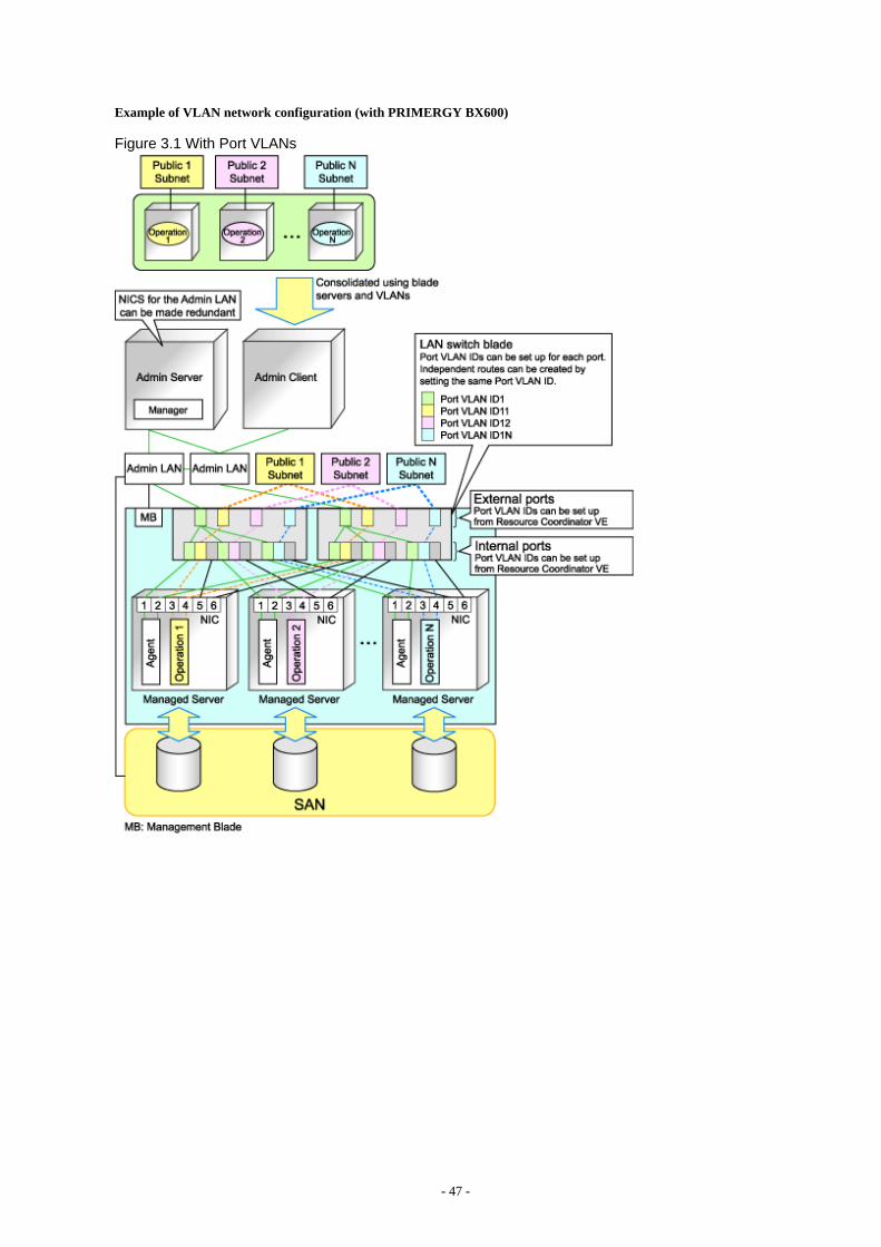
Example of VLAN network configuration (with PRIMERGY BX600)
Figure 3.1 With Port VLANs
- 47 -

Figure 3.2 With Tagged VLANs
Information
It is recommended that a dedicated admin LAN is installed as shown in "Example of VLAN network configuration (with PRIMERGYBX600)".If you need to use the following functions, a dedicated admin LAN is required in order to allocate admin IP addresses to the managedservers using the DHCP server included with Resource Coordinator VE.
- Backup and restore
- Collection and deployment of cloning images
- HBA address rename
In a configuration using a LAN switch blade, a VLAN has to be configured if the LAN switch blade is shared by an admin LAN anda public LAN where a dedicated admin LAN is required.
- 48 -

Required Network Configuration when Using HBA address rename
At startup a server set with HBA address rename needs to communicate with the Resource Coordinator VE manager. To enable startupof managed servers even when the manager is stopped, Resource Coordinator VE should be set according to one of the followingconfigurations.
- Manager cluster configuration with admin LAN redundancy using the redundant line control function of PRIMECLUSTER GLS
For details, refer to "Appendix B Manager Cluster Operation Settings and Deletion" in the "ServerView Resource Coordinator VEInstallation Guide".
- Dedicated HBA address rename server
This section describes the network configuration that is required for an environment with a dedicated HBA address rename server.For details about the HBA address rename setup service, refer to "6.2.2.1 Settings for the HBA address rename setup service".
- This service must be on the same admin LAN as the admin server. Do not start more than one instance of this service.
- This service uses NIC2 (Index2).Connect NIC2 of the managed server to the admin LAN.
NIC2 is the default value, and it can be changed when registering managed servers.For details, refer to "6.1.3 Registering Managed Servers".
- This service periodically obtains information about managed servers from the admin server and operates using this information. Forthis reason, it should be installed on a server that can be left active all the time.
- There must be two LAN cables between LAN switches (cascade connection) on the admin server and on the managed server.
Note
The HBA address rename setup service cannot operate on the same server as ServerView Deployment Manager, or on a server where anyother DHCP or PXE service is running.
The following diagram shows an example of how the HBA address rename setup service can be configured.
- 49 -

Figure 3.3 Sample Configuration Showing the HBA address rename Setup Service (with PRIMERGY BX600)
- Connections between LAN switches on the admin LAN can be made redundant using link aggregation.
- Connect the NIC2 (Index2) to the admin LAN (when it is the default).
- Configure the HBA address rename setup service on a server connected to the admin LAN. This server must be different from theadmin server.
- Ensure that the server or personal computer that is used to operate the HBA address rename setup service is always on when themanaged servers are active.
Network Configuration Required for VIOM Integration
When integrating with VIOM, the network configuration is defined by LAN switch blade and Intelligent Blade Panels.For details, refer to the ServerView Virtual-IO Manager manual.Refer to "6.1.1 Registering VIOM Coordination" for details.The following diagram shows an example of how the HBA address rename setup service can be configured.
- 50 -

Figure 3.4 Sample Configuration for VIOM Integration (on PRIMERGY BX900 Servers Using a SAN)
- 51 -

Figure 3.5 Sample Configuration for VIOM Integration (on PRIMERGY BX900 Servers Using iSCSI)
When using IBPs, the first IBP port should be connected to the admin LAN.On the adjacent admin LAN switch, the Spanning Tree Protocol (STP) should be disabled on the port connected to that first IBP port.
Functions Provided by Resource Coordinator VE
Resource Coordinator VE provides the following VLAN and port group management functions for PRIMERGY BX LAN switch blades.
- VLAN configuration
VLAN IDs of switch blade ports can be configured from the RC console.
- Exchange of VLAN IDs within each LAN switch blade in conjunction with server switchovers
When a server switchover occurs, the VLAN configuration of related LAN switch blades is automatically adjusted to preserve thenetwork connectivity of applications.VLAN IDs that were set on the LAN switch blade ports connected to the original server are exchanged with the VLAN IDs set on the
- 52 -

ports connected to the spare server, as shown in "Figure 3.6 VLAN Exchange Mechanism for Auto-Recovery, Server Switchover andServer Failback".
Figure 3.6 VLAN Exchange Mechanism for Auto-Recovery, Server Switchover and Server Failback
- Exchange of port groups in LAN switch blades during server switchovers
When a server switchover occurs, the port group configuration of related LAN switch blades (if in IBP mode) is automatically adjustedto preserve the network connectivity of applications.
Note
The targets of such VLAN ID and port group exchanges are the LAN switch blade ports connected to the switched over managed servers.If the switched over servers are connected to different LAN switch blades (e.g. when switching over managed servers in different chassis)the external ports of those LAN switches should be set with the same VLAN or port group configuration, and the switch blades placed inthe same network.
Network Configuration in Cases with Multiple Admin LAN Subnets [Windows]
In cases with multiple admin LAN subnets, configure the router settings.For details on how to configure these settings, refer to "3.6 Configuring the Network Environment".The following diagram shows an example of how configuring the network environment can be performed.
- 53 -

Figure 3.7 Network Configuration Example Involving Multiple Admin LAN Subnets
3.2.2 IP Addresses (Admin LAN)This section describes how to choose IP addresses for devices to be set on the admin LAN.
- IP address used by the admin server for management purposes
Choose an IP address for the network interface used to communicate with managed servers.This IP address will be asked during the manager's installation.Note that clients can also access the manager via IP addresses other than this admin LAN IP address, as long as those addresses wereset within the admin server operating system.
- IP addresses used by managed servers for management purposes
These are IP addresses that are used to communicate with the admin server.They are specified when a managed server is registered.For details on registering servers, refer to "6.1.3 Registering Managed Servers".When registering a server that will be used as a spare server, assign an IP address that does not conflict with IP addresses of othermanaged servers.Configure routing or gateway settings to enable communication with the admin server when placing the admin server in the differentsubnet.
- IP addresses used by other devices for management purposes
Configure routing or gateway settings to enable communication with the admin server when placing the admin server in the differentsubnet.
- LAN switch blades
- Server management units such as management blades or IPMI controllers
- 54 -

- Power monitoring devices
A management IP address must also be chosen for each of the following devices if they are to be registered into Resource CoordinatorVE. For the following components, IP addresses can be chosen either within or outside of the admin LAN.
- VM management software
IP address of the server which was installed using VM management software.
- LAN switches other than LAN switch blades
IP address used by the admin server to track network connections (topology) between managed servers (PRIMERGY BX) and theiradjacent LAN switches, and display them in the Network Map.
3.2.3 IP Addresses (iSCSI LAN)This section describes how to choose IP addresses for devices to be set on the iSCSI LAN.
Ensure that all of the IP addresses chosen here are on the same subnet.
- IP address of iSCSI initiator
Choose an IP address for the network interface to use for communication with managed servers.
- IP address of iSCSI target
The IP address of the storage devices which the iSCSI initiator will communicate.
Note
- IP addresses chosen for iSCSI should be static and do not used DHCP.
- When using a multi-path configuration, separate the networks using different ports.
3.2.4 Public LAN Settings for Managed ServersThe network parameters for the NIC of the managed server will be configured automatically when a cloning image is deployed.For how to set up a managed server in a public LAN, refer to "8.6 Network Parameter Auto-Configuration for Cloning Images".
3.2.5 LAN Switch SettingsChoose the following settings for LAN switches that will be managed by Resource Coordinator VE.
- Telnet login user name
This user name can contain up to 64 alphanumeric characters (upper or lower case), underscores ("_"), and hyphens ("-").
- Telnet password
This password can contain up to 80 alphanumeric characters (upper or lower case) and symbols (ASCII characters 0x20, 0x21, and0x23 to 0x7e) with the exception of double quotation marks ( " ).
- Administrator password
This password can contain up to 80 alphanumeric characters (upper or lower case) and symbols (ASCII characters 0x20, 0x21, and0x23 to 0x7e) with the exception of double quotation marks ( " ).
- SNMP community name
This user name can contain up to 32 alphanumeric characters (upper or lower case), underscores ("_"), and hyphens ("-").
- SNMP trap destination
The SNMP trap destination must be the admin server's IP address.
- 55 -

Note
Depending on the LAN switch used, setting an SNMP trap destination may restrict SNMP access to that switch.In a clustered manager configuration, set the physical IP addresses of both the primary and secondary nodes as SNMP trap destinations.If the LAN switch is set to only grant access from known IP addresses, be sure to give permissions to the physical IP addresses ofboth the primary and secondary cluster nodes, as is done with trap destination settings.For details, refer to the LAN switch manual.
Information
Character limitations may vary depending on the LAN switch used.For details, refer to the LAN switch manual.
In order to track the network connections between managed servers (PRIMERGY BX) and adjacent LAN switches, and display them inthe Network Map, the following protocols should be first enabled on each LAN switch (including LAN switch blades).
- LLDP (Link layer Discovery Protocol)
- CDP (Cisco Discovery Protocol)
Note
- Adjacent LAN switches should be set to use the same protocol.For details, refer to LAN switch manuals.If a LAN switch blade does not support either one of those two protocols (LLDP or CDP), it should be set up to use the supportedprotocol.
- Resource Coordinator VE cannot detect the network connections between a LAN switch blade set in IBP mode and its adjacent LANswitches.
- For the following LAN switch blade, the settings described below should be set to the same value to enable proper detection of networklinks.
LAN switch blades
- PY CB Eth Switch/IBP 1Gb 36/12
- PY CB Eth Switch/IBP 1Gb 36/8+2
- PY CB Eth Switch/IBP 1Gb 18/6
Expected value
- hostname set from the hostname command
- system name set from the snmp-server sysname command
Example
When setting both the hostname and system name to "swb1".
# hostname swb1# snmp-server sysname swb1
- For the following LAN switch blade, the settings described below should be set to the same value to enable proper detection of networklinks.
LAN switch blades
- PY CB Eth Switch/IBP 10Gb 18/8
Configuration
- 56 -

- Using the snmp agent address command, set the admin IP address of the LAN switch blade for the agent address.
- Network connections may not be displayed properly if two or more LAN switches are set with a conflicting system name (sysName).
3.3 Defining the Storage EnvironmentThis section explains how to define the storage environment settings required for a Resource Coordinator VE setup.
3.3.1 Storage ConfigurationDefine the storage configuration required for the system.
Resource Coordinator VE supports the following configurations.
Table 3.1 Supported Storage Device Configurations
Configuration System disk Data disk(s)
1 SAN storage SAN storage
2 Local disk (*1) Local disk (*1), NAS
3 Local disk (*1) SAN storage
4 iSCSI storage iSCSI storage (*2)
5 (*3) Local disk (*1) iSCSI storage
*1: A local disk refers either to a server's internal disk, or to one stored in a storage blade.*2: When using data disks, use the hardware initiator. As there is a chance that data will be damaged, do not perform collection ordistribution of a cloning image using a software initiator.*3: When using this configuration, use a combination of the settings for the VLAN settings for LAN switch ports connected to the softwareinitiator and the LAN for iSCSI disks. Configure the VLAN settings for LAN switch ports connected to primary servers and iSCSI storages.Do not configure the settings for ports connected to spare servers and servers that are the target of cloning image deployment.
Information
- Configurations 1, 3, and 4 support I/O virtualization.
- When using HBA address rename, server switchover can only be performed on servers that are connected to a single SAN/iSCSIstorage system. Resource Coordinator VE does not support a server's switchover when it is connected to multiple SAN storage systems.
- When performing server switchover using VIOM, multiple storage devices can be connected to a single server. This is because the storage startup order for BIOS settings can be taken over during server switchover.
- A SAN storage system can be used as a shared cluster disk.However, a server which is defined in a cluster cannot be switched over.
- Resource Coordinator VE supports both single path and multi-path storage connections for SAN/iSCSI.
- When server switchover is performed in configuration 5, the settings to automatically change VLAN settings during server switchoverare necessary.
- The following operations are necessary when collecting cloning images in configuration 5.
[Windows]After completing collection of cloning images, restart the server or mount the iSCSI disks.
[Linux]Before collecting cloning images, remove the fsck check on OS startup, for the mounting settings of iSCSI disks. Also, after completingcollection of cloning images, restart the server or mount the iSCSI disks.
- When deploying cloning images in configuration 5, after completing deployment, change the software initiator settings beforeconfiguring VLAN settings of LAN switch ports connected to the LAN for iSCSI disks on the destination server. When there are
- 57 -

multiple servers with the same software initiator settings, check if there are any problems in the modified settings, as there is a chancethat data may be damaged.
- In configurations where the system disk is SAN storage and the data disk is a local disk, the settings can be used in the range excludinguse of the backup and restore, server switchover and cloning functions.
Functions Provided by Resource Coordinator VE
The I/O virtualization features available with Resource Coordinator VE allow spare servers to inherit the WWN of primary servers, theMAC address of NICs, and boot and network configurations. As a result, there is no longer any need to reconfigure the storage devicesconnected to the involved servers. In environments where I/O virtualization cannot be used, the server can be switched, by changing theconfigurations of the Fibre Channel Switch and storage unit connected to the servers.Note that WWN is a general term for both WWNN and WWPN. WWNN stands for node name and WWPN stands for port name.The following example shows how server switchovers occur.
Figure 3.8 Example of a Server Switchover Based on I/O Virtualization (When WWNs are Switched)
3.3.2 HBA and Storage Device SettingsSystem configuration requires that the relationship between physical servers and HBA WWNs from the perspective of the server, and therelationship between storage volumes and HBA WWNs from the perspective of storage devices be defined clearly.An example where blades connect to storage devices via multiple paths using two HBA ports is shown below.Refer to the manual of each storage device for details.
Note
Resource Coordinator VE does not support configurations where managed servers are mounted with three or more HBA ports.
- 58 -
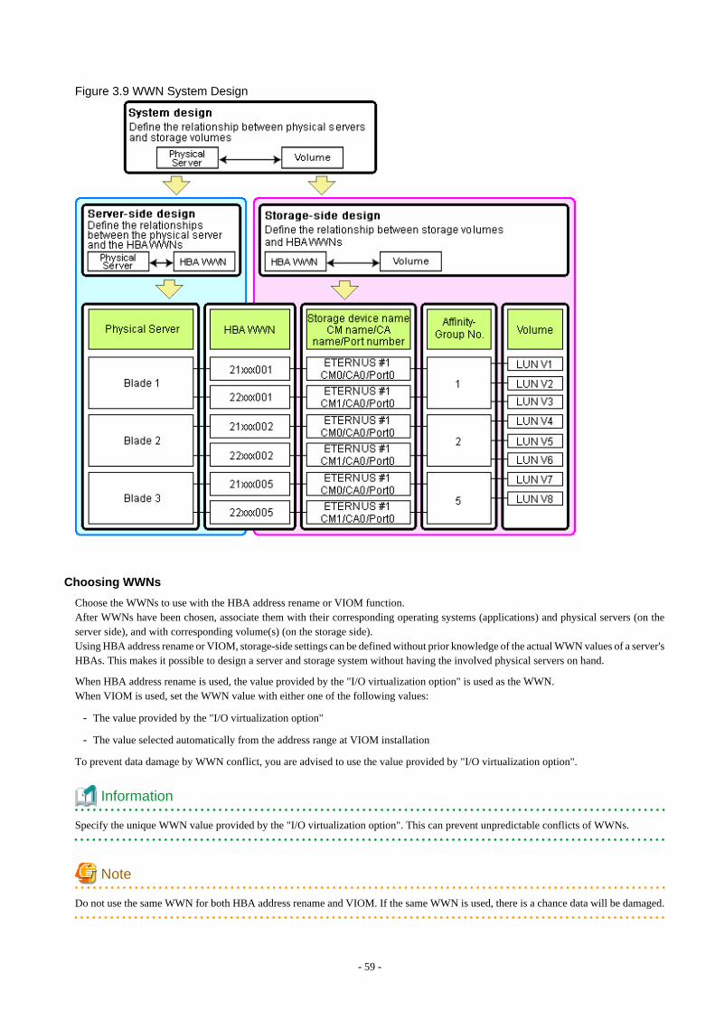
Figure 3.9 WWN System Design
Choosing WWNs
Choose the WWNs to use with the HBA address rename or VIOM function.After WWNs have been chosen, associate them with their corresponding operating systems (applications) and physical servers (on theserver side), and with corresponding volume(s) (on the storage side).Using HBA address rename or VIOM, storage-side settings can be defined without prior knowledge of the actual WWN values of a server'sHBAs. This makes it possible to design a server and storage system without having the involved physical servers on hand.
When HBA address rename is used, the value provided by the "I/O virtualization option" is used as the WWN.When VIOM is used, set the WWN value with either one of the following values:
- The value provided by the "I/O virtualization option"
- The value selected automatically from the address range at VIOM installation
To prevent data damage by WWN conflict, you are advised to use the value provided by "I/O virtualization option".
Information
Specify the unique WWN value provided by the "I/O virtualization option". This can prevent unpredictable conflicts of WWNs.
Note
Do not use the same WWN for both HBA address rename and VIOM. If the same WWN is used, there is a chance data will be damaged.
- 59 -

The WWN format used by the HBA address rename and VIOM functions are as follows:
The "2x" part at the start of the provided WWN can define either a WWNN or a WWPN. Define and use each of them as follows.
- 20: Use as a WWNN
- 2x: Use as a WWPN
With HBA address rename, x will be allocated to the I/O addresses of HBA adapters in descending order.I/O addresses of HBA adapters can be confirmed using the HBA BIOS or other tools provided by HBA vendors.
Note
With HBA address rename, as WWNs are allocated to the I/O addresses of HBAs in descending order, the order may not match the portorder listed in the HBA.
For details, refer to "Appendix I WWN Allocation Order During HBA address rename Configuration".
The WWN chosen here would be used for the system design of the servers and storage.
- Server-side design
WWNs are used in server-side design by assigning one unique to each server.
- Storage-side design
One or more volumes are chosen for each server, and the corresponding WWN assigned to each server in the server-side design isconfigured on the storage-side for those volumes.
Defining WWN settings for VIOM
VIOM should be configured first. Then, storage devices should also be configured in accordance with the WWN settings that were definedwithin VIOM.
3.3.3 iSCSI Interface and Storage Device Settings (iSCSI)System configuration requires that the relationship between physical servers and the IQN of the iSCSI adaptor from the perspective of theserver, and the relationship between storage volumes and the IQN of iSCSI from the perspective of storage devices, be defined clearly.An example where blades connect to storage devices via multiple paths using two iSCSI interface ports is shown below.Refer to the manual of each storage device for details.
- 60 -

Figure 3.10 IQN System Design
Choosing IQNs
Choose the IQNs to use with the iSCSI.After IQNs have been chosen, associate them with their corresponding operating systems (applications) and physical servers (on the serverside), and with corresponding volume(s) (on the storage side).IQNs are made up of the following:
- Type identifier "iqn."
- Domain acquisition date
- Domain name
- Character string assigned by domain acquirer
IQNs must be unique.Create a unique IQN by using the server name, or the MAC address provided by the "I/O virtualization option" that is to be allocated tothe network interface of the server, as part of the IQN.If IQNs overlap, there is a chance that data will be damaged when accessed simultaneously.An example of using the virtual MAC address allocated by the "I/O virtualization option" is given below.
Example
When the MAC address is 00:00:00:00:00:FF
IQN iqn.2010-04.com.fujitsu:0000000000ff
- 61 -

The IQN chosen here would be used for the system design of the servers and storage.
- Server-side design
IQNs are used in server-side design by assigning one unique to each server.
- Storage-side design
One or more volumes are chosen for each server, and the corresponding IQN assigned to each server in the server-side design isconfigured on the storage-side for those volumes.
3.3.4 Settings for ETERNUS SF Storage Cruiser IntegrationWhen integrating with ESC, it should be configured first. Register the Fibre Channel switches and storage units connected to primaryservers and managed servers on ESC.
Note
When integrating with ESC, do not register servers used as spare server for Resource Coordinator VE on ESC.
After registration, collect WWNs of HBAs set on physical servers or WWNs of CAs set on storage units.
Collection of WWNs of HBA Set on Physical Servers
From the client window of ESC, collect the WWNs for HBAs contained in the registered servers.For servers which are not registered on ESC, collect WWNs from the seal driver utilities provided with HBA cards.Refer to the storage device manual of each storage device for details.
Collection of WWNs of CA Set on Storage Units
From the client window of ESC, collect the WWNs for HBAs contained in the registered storage.Refer to the storage device manual of each storage device for details.
Collected WWNs are reflected in the relationship between physical servers and HBA WWNs from the perspective of the server, and inthe relationship between the storage CA and WWNs from the perspective of storage devices.System configuration requires that the relationship between HBA WWNs, storage CA WWNs, and volumes from the perspective of storagedevices be defined clearly.When using a multi-path configuration, design the values to match the order of HBAs configured as primary servers or spare servers withthose of the corresponding CAs.
Information
For integration with ESC, Resource Coordinator VE supports configurations where managed servers have up to eight HBA ports mounted.
3.4 Defining the Power Monitoring Device EnvironmentThis section explains how to define the power monitoring environment settings required for a Resource Coordinator VE setup.
3.4.1 Settings for the Power Monitoring EnvironmentTo monitor power consumption, choose values for the following settings.
Polling interval
This determines the time interval for collecting the power consumption data.The possible values that can be set are any value (at one minute intervals) between 1 and 6 minutes, or 10 minutes. The default is 5minutes.
Data storage period
This defines the storage period for the collected environmental data.
- 62 -

Table 3.2 Storage Period Values for Power Monitoring Data
Data Sampling RateLifespan (Unit: month)
Default Value Maximum Value
Finest sampling (The most detailed data secured at the pollinginterval)
1 12
Hourly sampling 1 60
Daily sampling 12 120
Monthly sampling 60 300
Yearly sampling 60 600
3.4.2 Power Monitoring Device SettingsChoose values for the following power monitoring device (PDU or UPS) settings. If any of those settings is already determined by othersoftware, use that value.
Device name
This is the name that identifies the power monitoring device. Each device name should be unique within the system. The first charactermust be alphabetic, and the name can contain up to 15 alphanumeric characters and hyphens ("-").
Admin IP address
This IP address must be in the same subnet as the admin server.
SNMP community name
This community name can contain up to 32 alphanumeric characters, underscores ("_"), and hyphens ("-").
Voltage
This is the voltage (V) supplied to the power monitoring device.
Comments
These comments can be any description desired for the power monitoring device. The comments can contain up to 128 characters.
3.5 Configuring the Server EnvironmentThis section describes how to configure servers and chassis for Resource Coordinator VE.
Chassis Settings (for Blade Servers)
Refer to the management blade manual to apply the settings chosen in "3.1.1 Chassis Settings (For blade server environments)" to themanagement blade.Note that the SNMP community must be set to Write (read and write) access.
- Admin IP address (IP address of the management blade)
- SNMP Community
- SNMP trap destination
The SNMP trap destination must be the admin server's IP address.
Refer to the management blade manual to set the following SNMP agent settings.
- Set Agent SNMP Enable
Set to "enable".
- Set Agent SNMP Security Enable
Set to "disable".
- 63 -

Note
When powering off a chassis together with its enclosed server blades, servers are shut down using the graceful shutdown option of themanagement blade. To enable this feature, all servers within the chassis should have a ServerView Agent installed.
Chassis Settings (PRIMERGY Partition Models)
Refer to the management board manual to apply the settings chosen in "3.1.4 Chassis Settings (Settings for PRIMERGY PartitionModels)" to the management board.Note that the SNMP community must be set to Write (read and write) access.
- Admin IP address (Virtual IP address of the management board)
- User name
- Password
- SNMP community
- SNMP trap destination
The SNMP trap destination must be the admin server's IP address.
Enable the following function referring the instructions given in the management board's manual.
- SNMP agent
Mode Switch Settings for the Operator Panel (SPARC Enterprise M Series Servers)
When managing SPARC Enterprise M series servers using Resource Coordinator VE, set the mode switch of operator panel to "Locked"in the OpenBoot configuration to automatically start up the OS when powering on SPARC Enterprise M series servers.
Chassis Settings (SPARC Enterprise M4000/M5000/M8000/M9000 servers)
Refer to the remote management controller manual to apply the settings chosen in "3.1.5 Chassis Settings (SPARC Enterprise M4000/M5000/M8000/M9000 servers)" to the management blade.Note that the SNMP community must be set to Write (read and write) access.
- Admin IP address (IP address of the remote management controller)
- User name
- Password
- SNMP community
- SNMP trap destination
The SNMP trap destination must be the admin server's IP address.
Refer to the instructions given in the XSCF manual and enable the following functions.
- SNMP agent
- SSH service
- HTTPS service
- Domain autoboot
- 64 -

Remote Management Controller Settings (for Non-Blade Servers)
Refer to the remote management controller manual to configure the following on the IPMI controller.
- IP address
- User name
- Password
- SNMP community (for SPARC Enterprise servers)
- SNMP trap destination
The SNMP trap destination must be the admin server's IP address.
For SPARC Enterprise M3000 servers, refer to the XSCF manual and enable the following services.
- SNMP agent
- SSH service
- HTTPS service
- Domain autoboot
For SPARC Enterprise T series servers, refer to the ILOM manual and enable the following services.
- SNMP agent
- SSH configuration
- HTTPS configuration
- IPMI status
Note
When assigning multiple IP addresses to multiple network interfaces on a XSCF module, make sure that the IP address used by ResourceCoordinator VE is assigned to the first of those network interfaces.
BIOS Settings for Managed Servers
The following BIOS configurations must be modified.
System BIOS
This is the system BIOS for a managed server.Enable or disable the internal SCSI BIOS and FC-HBA BIOS as appropriate, and set up the appropriate boot order.
Note
- The BIOS settings of server blades include an option to automatically start up servers when their enclosing chassis is powered on.For details, refer to the server blade manual.
- For PRIMERGY BX900/BX400, when an LND-PG203 is mounted as the LAN expansion card of the server blade, do not set theNIC of the LAN expansion card as "disable" in the server blade's BIOS settings.The connections between server blades and LAN switch blades are not shown correctly, when "disable" is set.The following functions do not operate correctly.
- Changing and setting the VLAN for LAN switch blades (internal and external ports)
- Server switchover (changing network settings while a server is switched over)
- 65 -

Internal SCSI BIOS
These are the BIOS settings for the internal SCSI disk(s) of a managed server.Enable or disable booting from internal disks as appropriate.
FC-HBA BIOS
This is a BIOS setting that relates to FC-HBAs that have been installed as an expansion card in the blade server.Enable or disable SAN boot as well as the connection of a SAN storage environment by means of a Fibre Channel switch.
Configure the following settings depending on the operating environment.
- When using the backup/restore or cloning function
System BIOS
Set the boot order as follows.
1. Boot from the first admin LAN network interface (NIC1 (Index1))
2. Boot from the network interface used by the admin LAN (NIC2 (Index2))
3. Boot from CD-ROM (when a CD-ROM drive is connected)
4. Boot from the disk
Note
- Do not change the boot order once a primary server has commenced operation. Even when booting from disk, there is no needto change the boot order.
- Step 2 is only required for a redundant admin LAN configuration.
- NICs other than NIC1 and NIC2 can also be used for the admin LAN. In this case, switch the order of step 1. and step 2. Whenusing NICs other than NIC1 and NIC2 for the admin LAN, specify the same NIC configured in this procedure when registeringthe server.For details, refer to "6.1.3 Registering Managed Servers".
Internal SCSI BIOS
The servers to which a cloning image is deployed should have the same internal SCSI BIOS settings as those of the server fromwhich the image was collected. Similarly, when using server switchover, primary servers and their spare servers should have thesame internal SCSI BIOS settings.
FC-HBA BIOS
When using HBA address rename and SAN storage only for data storing purposes, disable boot from SAN. Refer to the manualof each FC-HBA for details on FC-HBA BIOS settings.This setting is only required if a SAN storage system is used.
- When using HBA address rename for SAN boot
System BIOS
Enable the FC-HBA BIOS.Set the boot order as follows.
1. Boot from the first admin LAN network interface (NIC1 (Index1))
2. Boot from the network interface used by the admin LAN (NIC2 (Index2))
3. Boot from CD-ROM (when a CD-ROM drive is connected)
4. Boot from a storage device
- 66 -

Note
- Do not change the boot order once a primary server has commenced operation. Even when booting from disk, there is no needto change the boot order.
- NICs other than NIC1 and NIC2 can also be used for the admin LAN. In this case, switch the order of step 1. and step 2. Whenusing NICs other than NIC1 and NIC2 for the admin LAN, specify the same NIC configured in this procedure when registeringthe server.For details, refer to "6.1.3 Registering Managed Servers".
Internal SCSI BIOS
If the managed server does not have an internal SCSI disk, disable the option to boot from an internal SCSI disk. However, insome cases (depending on a combination of factors such as server model, HBA model, and firmware), this option should eitherbe enabled or disabled. Refer to the FC-HBA manual for instructions on whether or not to enable or disable boot from internalSCSI disk.
FC-HBA BIOS
Enable booting from SAN storage devices.
Refer to the manual of each FC-HBA for details on FC-HBA BIOS settings.
Note
- Restart the server saving BIOS configuration changes.
- HBA address rename may not work properly with older BIOS firmware versions.Please obtain and update the latest BIOS firmware from the following page.
URL: http://www.fujitsu.com/global/services/computing/server/ia/ (As of August 2011)
- When using VIOM (SAN boot)
System BIOS
Enable the FC-HBA BIOS.Set the boot order as follows.
1. Boot from the first admin LAN network interface (NIC1 (Index1))
2. Boot from the network interface used by the admin LAN (NIC2 (Index2))
3. Boot from CD-ROM (when a CD-ROM drive is connected)
4. Boot from a storage device
Note
NICs other than NIC1 and NIC2 can also be used for the admin LAN. In this case, switch the order of step 1. and step 2. Whenusing NICs other than NIC1 and NIC2 for the admin LAN, specify the same NIC configured in this procedure when registeringthe server.For details, refer to "6.1.3 Registering Managed Servers".
Internal SCSI BIOS
Apply the same settings as those described in the above "When using HBA address rename for SAN boot" section.
FC-HBA BIOS
Apply the same settings as those described in the above "When using HBA address rename for SAN boot" section.
- 67 -

- When using VIOM (iSCSI boot)
System BIOS
Enable iSCSI boot for the NIC which is used for the iSCSI LAN.Use the VIOM server profile for the iSCSI boot parameter settings.For details on server profile setup, refer to the ServerView Virtual-IO Manager manual.Set the boot order as follows.
1. Boot from the first admin LAN network interface (NIC1 (Index1))
2. Boot from the network interface used by the admin LAN (NIC2 (Index2))
3. Boot from the network interface used for the iSCSI LAN (NIC3 (Index3))
4. Boot from the network interface used for the iSCSI LAN (NIC4 (Index4))
Note
- Do not change the boot order once a primary server has commenced operation. Even when booting from disk, there is no needto change the boot order.
- NICs other than NIC1 and NIC2 can also be used for the admin LAN. In this case, switch the order of step 1. and step 2. Whenusing NICs other than NIC1 and NIC2 for the admin LAN, specify the same NIC configured in this procedure when registeringthe server.For details, refer to "6.1.3 Registering Managed Servers".
- When using NIC3 or NIC4 for the admin LAN, use NICs other than NIC3 and NIC4 for the iSCSI LAN. In this case, switchthe order of step 3. and step 4.
Internal SCSI BIOS
If the managed server does not have an internal SCSI disk, disable the option to boot from an internal SCSI disk. However, insome cases (depending on a combination of factors such as server, model, and firmware), this option should either be enabled ordisabled. Refer to the hardware manual for instructions on whether or not to enable or disable boot from internal SCSI disk.
FC-HBA BIOS
Disable the function.
- When using VIOM (Local boot)
Apply the same settings as those described in the above "When using the backup/restore or cloning function" section.
OS Settings for Managed Servers
When using the following functions, configure the OS to respond to ping commands.
- Auto-Recovery (for rack mount or tower servers)
- Configuration of monitoring information (ping monitoring)
Settings for Server Virtualization Software
Server virtualization software must be configured appropriately for Resource Coordinator VE.
Refer to "A.2 Configuration Requirements" for details on the required server virtualization software settings.
OBP (Open Boot Prom) Settings (SPARC Enterprise)
When managing SPARC Enterprise servers from Resource Coordinator VE, set the "autoboot?" option to "true" in the OBP configuration.Otherwise, the operating system will not automatically start up when powering on SPARC Enterprise servers.
- 68 -

- SAN boot settings
Configure the following settings on OBP for automatic boot from SAN storage devices.
- auto-boot?
Set to "true".
- boot-device
Set with a boot disk identifier at the beginning.
Configure the following settings on OBP for HBAs connected to the boot disk.
- HBA boot
Enable the function.
- Topology
Set to NPORT connection.
- Target devices
Configure based on values set in "3.3.4 Settings for ETERNUS SF Storage Cruiser Integration".
For details, refer to "SPARC Enterprise - ETERNUS SAN Boot Environment Build Guide" of the Fibre Channel card driver manual.
Settings for ServerView Operations Manager (VMware ESXi)
When managing VMware ESXi using Resource Coordinator VE, register the target VMware ESXi with ServerView Operations Manager.
For details, refer to the ServerView Operations Manager manual.
3.6 Configuring the Network EnvironmentThis section describes how to configure LAN switches and routers for Resource Coordinator VE.
LAN Switch Settings
- LAN switch blades
Refer to the LAN switch blade manual to apply the following settings.
- VLAN IDs for the admin LAN ports used to communicate with the admin server, as chosen in "3.2.1 Network Configuration"
- Settings chosen in "3.2.5 LAN Switch Settings"
Information
VLAN settings for switch blade ports not used for the admin LAN can also be set from the RC console. Refer to "6.2.1 ConfiguringVLANs on LAN Switches" for details.
Note
After setting up a LAN switch blade, perform a backup of the LAN switch blade's configuration. For details how to backup theconfiguration of a switch blade, refer to the manual of the LAN switch blade.
However, settings other than VLAN settings should be made directly on the LAN switch blade.
- LAN switches other than LAN switch blades
Refer to the LAN switch manual to apply the settings chosen in "3.2.5 LAN Switch Settings".
- 69 -
Note
Resource Coordinator VE uses telnet to log into LAN switch blades and automate settings.When telnet connection is disabled, enable it.Refer to the manual of the relevant product.Some models may restrict the number of simultaneous connections. In this case, log out from other telnet connections.
If telnet is unavailable, the following features are also unavailable.
- Registration of LAN switch blades
- Changing of LAN switch blade settings
- Changing and setting the VLAN for LAN switch blades (internal and external ports)
- Restoration of LAN switch blades
- Server switchover (changing network settings while a server is switched over)
For PY CB Eth Switch/IBP 10Gb 18/8, the maximum unregistered VLAN ID is used for the "oob" port in the LAN switch blade. Whenthe maximum VLAN ID is set "4094" in the LAN switch blade and the "oob" port is used to connect the telnet, the following functionscannot be used.
- Changing and setting the VLAN for LAN switch blades (internal and external ports)
- Restoration of LAN switch blades
- Server switchover (changing network settings while a server is switched over)
Router Settings
For the router connections between different subnets, configure the following router settings.
- For managed servers, configure routing to enable communication with the admin LAN IP address of the admin server.
- On the managed servers, configure the following multicast routing settings for manage resources.
225.1.0.1 - 225.1.0.8
- When using the following functions, configure the DHCP relay agent settings so managers can accept DHCP requests from the managedservers belonging to different subnets.
- Backup and restore of managed servers
- Collection and deployment of cloning images
- SAN boot using HBA address rename
- When using the HBA address rename setup service, configure the DHCP relay agent settings so the HBA address rename setup servicecan accept DHCP requests from managed servers belonging to different subnets.
- When setting firewalls, etc. for the router, permit connections for the ports used by Resource Coordinator VE.Refer to "Appendix C Port List", for details on the ports used by Resource Coordinator VE.
3.7 Configuring the Storage EnvironmentThis section describes how to configure storage devices for Resource Coordinator VE.
Storage Device Settings
Using the HBA address rename function, VIOM, or ESC integration requires adequate preparation of storage environment settings (asdescribed below).When using VIOM, configure storage devices according to the WWN assigned to each server.SAN storage settings can be configured using storage management software (such as ETERNUSmgr, ETERNUS SF Storage Cruiser or
- 70 -

others). For details, refer to the manual of the relevant product.The storage settings mentioned here are those that apply to the servers to be managed with I/O virtualization.If storage settings (zoning, LUN masking or any other security setting) were already made for SAN, those settings should be cancelledand re-defined using the server-side WWN settings chosen in "3.3.2 HBA and Storage Device Settings".
Setting up Logical Volumes and Affinity Groups
The logical volumes for storage devices and affinity groups allocated for servers must be configured.These settings can be configured easily using either storage management software (such as ETERNUSmgr or the Storage VolumeConfiguration Navigator feature of ETERNUS SF Storage Cruiser).
Access Path Settings
For ESC integration, no preparation is required.Using the HBA address rename function or VIOM integration requires adequate preparation.Access paths between servers and storage devices must be made by applying the WWPN values chosen in "3.3.2 HBA and StorageDevice Settings" to each server HBA. This will allow servers to access storage devices.To configure storage devices and Fibre Channel switches on SAN, use the appropriate storage management software.Note that these configurations are best performed using the ETERNUS SF Storage Cruiser's storageadm zone command.
- Using the ETERNUS SF Storage Cruiser's storageadm zone command for SAN settings
After registering the storage for management in the ETERNUS SF Storage Cruiser manager, set up access paths using the "add"parameter of the storageadm zone command, based on the storage-side designs that were chosen in "3.3.2 HBA and Storage DeviceSettings".The WWPN of the target storage device CA port must be specified with the storageadm zone command.As it is necessary to specify the WWPN of the CA port of the relevant storage, do so using either storage management software (suchas ETERNUSmgr) or ETERNUS SF Storage Cruiser after the storage device has been configured.Refer to the ETERNUS SF Storage Cruiser manual for details on the storageadm zone command, configurable storage devices, andthe graphical interface used to check access path settings.
Note
For access paths, point-to-point WWPN zoning is required.Zoning (or port zoning) is required for configuring access paths.
3.8 Configuring the Power Monitoring EnvironmentThis section describes how to configure power monitor devices for Resource Coordinator VE.
Apply the following settings to power monitoring targets. Refer to the manual of each power monitoring target for configurationinstructions.
Admin IP address
This IP address is used by the admin server to communicate with a power monitoring target.
SNMP community name
This SNMP community name is used by the admin server to collect power consumption data from a power monitoring target (via theSNMP protocol).
- 71 -

Chapter 4 InstallationInstallation of Resource Coordinator VE requires the preparations described in "Chapter 3 System Design and Initial Setup" to be performedfirst.For details on how to install Resource Coordinator VE, refer to the "ServerView Resource Coordinator VE Installation Guide".
- 72 -
Chapter 5 Starting and StoppingThis chapter explains how to start and stop the Resource Coordinator VE manager and agent services, how to check their running state,and how to open and close the RC console.
Managers and agents start automatically when their respective servers are powered on. Normally no special operation is required to startthem.
Note
When using the HBA address rename function, ensure that the manager is started before powering on any managed servers. When usingpower management the procedure should be managed as follows: start the admin server together with storage devices, then start managedservers 10 minutes later.Managed servers will not boot up properly if they are started before the manager. Make sure that the manager is running before turningon the managed servers.Additionally, when using the HBA address rename function, the HBA address rename setup service should be started on a server and leftrunning all the time. For details on starting, stopping and checking the state of the HBA address rename setup service, refer to "6.2.2.1Settings for the HBA address rename setup service".
5.1 ManagerThe Resource Coordinator VE manager starts automatically on the admin server.This section explains how to manually start or stop the manager and how to check its running state.
[Windows]The manager is made up of the following two groups of Windows services:
- Manager services
Resource Coordinator ManagerResource Coordinator Task ManagerResource Coordinator Web Server(Apache)Resource Coordinator Sub Web Server(Mongrel)Resource Coordinator Sub Web Server(Mongrel2)Resource Coordinator DB Server(PostgreSQL)
- Related services
Deployment ServiceTFTP ServicePXE ServicesDHCP Server (*1)
*1: Required when managed servers belonging to different subnets from the admin server exist.
From the Windows Control Panel, open "Administrative Tools". Then, open the [Services] window to check the state of each service.
Services are started and stopped using the rcxadm mgrctl command (start and stop subcommands). As this command collectively controlsboth manager and related services, use the command to start and stop services.
For details on these commands, refer to "5.7 rcxadm mgrctl" of the "ServerView Resource Coordinator VE Command Reference".
To start or stop a manager in a clustered configuration, right-click the manager application shown under the failover cluster manager tree,and select either [Bring this service or application online] or [Take this service or application offline].
[Linux]The manager is made up of the following two groups of Linux services.
- Manager services
rcvmr
- 73 -
Manager services also include the following daemons.
rcxmanagerrcxtaskmgrrcxmongrel1rcxmongrel2rcxhttpd
- Related services
scwdepsvdscwpxesvdscwtftpd
The status of each of those services can be confirmed from the service command, as shown below.
# service rcvmr status <RETURN># service scwdepsvd status <RETURN># service scwpxesvd status <RETURN># service scwtftpd status <RETURN>
Services are started and stopped using the rcxadm mgrctl command (start and stop subcommands). As this command collectively controlsboth manager and related services, use the command to start and stop services.For details on these commands, refer to "5.7 rcxadm mgrctl" of the "ServerView Resource Coordinator VE Command Reference".
To start or stop a manager in a clustered configuration, use the cluster administration view (Cluster Admin).
For details, refer to the PRIMECLUSTER manual.
Note
- If ServerView Deployment Manager is used on the Admin LAN, the deployment services of Resource Coordinator VE areautomatically disabled. To prevent conflicts with ServerView Deployment Manager, those services should never be started. Refer to"Appendix J Co-Existence with ServerView Deployment Manager" for details.
- Resource Coordinator VE cannot operate if any of the manager services are stopped. Ensure that all services are running when ResourceCoordinator VE is running.
- If the manager is unable to communicate on the admin LAN when started up (because of LAN cable disconnections or any othercauses), PXE Services may not start automatically. If PXE Services are stopped, investigate the network interface used for the adminLAN and confirm whether it can communicate with other nodes on the admin LAN.
If the manager cannot communicate with admin LAN nodes, restore the admin LAN itself and restart the manager.
5.2 AgentThe Resource Coordinator VE agent starts automatically on managed servers.This section explains how to manually start or stop an agent and how to check its power state.
Note
To prevent conflicts, the deployment service is uninstalled from the Resource Coordinator VE agent when using ServerView DeploymentManager on the admin LAN. In such cases, there is no need to start or stop the deployment service when starting or stopping the ResourceCoordinator VE agent.
[Windows/Hyper-V]The agent consists of the following two Windows services.
- Agent service
Resource Coordinator Agent
- 74 -

- Related services
Deployment Agent
From the Windows Control Panel, open "Administrative Tools". Then, open the [Services] window to check the state of each service.The following explains how to start and stop each service.
- Agent service
Agents can be started and stopped using the start and stop subcommands of the rcxadm agtctl command.For details on the command, refer to "5.1 rcxadm agtctl" of the "ServerView Resource Coordinator VE Command Reference".
- Related services
From the Windows Control Panel, open "Administrative Tools". Then, open the [Services] window to stop or start the DeploymentAgent service.
[Linux/VMware/Xen]The agent consists of the following services.
- Agent service
- Related services
Execute the following commands to determine whether the agent is running or not. If those commands show that the processes for theagent and deployment services are running, then the agent can be asserted to be running.
- Agent service
# /bin/ps -ef | grep FJSVssagt <RETURN>
- Related services
# /bin/ps -ef | grep scwagent <RETURN>
The following explains how to start and stop each service.
- Agent service
Agents can be started and stopped using the start and stop subcommands of the rcxadm agtctl command.For details on the command, refer to "5.1 rcxadm agtctl" of the "ServerView Resource Coordinator VE Command Reference".
- Related services
Execute the following command to start or stop the collection of image files, deployment of image files, and server startup control.
Start
# /etc/init.d/scwagent start <RETURN>
Stop
# /etc/init.d/scwagent stop <RETURN>
[Solaris]The agent consists of the following services.
- Agent service
Execute the following commands to determine whether the agent is running or not. If those commands show that the processes forthe agent and deployment services are running, then the agent can be asserted to be running.
# /bin/ps -ef | grep FJSVrcvat <RETURN>
The following explains how to start and stop each service.
Agents can be started and stopped using the start and stop subcommands of the rcxadm agtctl command.For details on the command, refer to "5.1 rcxadm agtctl" of the "ServerView Resource Coordinator VE Command Reference".
- 75 -
5.3 RC ConsoleThis section describes how to open and close the RC console.
Note
- When accessing the RC console from Internet Explorer 8 or 9, be sure to enable the Compatibility View in Internet Explorer.
- The RC console uses the Web browser's standard fonts and is best viewed in a window size of 1024 by 768 pixels. If the Web browseris resized a significant amount, the display quality may deteriorate.
- The RC console uses JavaScript, Cookies, and IFRAMEs. These must be enabled in the Web browser settings before using the RCconsole.
Opening the RC Console
Start a Web browser from an admin client and specify the URL of the RC console for connection.If the port number was changed, specify the new port number.
When Single Sign-On has been configured, the login window for Single Sign-On will be displayed. When Single Sign-On authenticationhas already been performed, the RC console can be started without displaying the login window.When Single Sign-On is not configured, the login window for Resource Coordinator VE will be displayed.Refer to "H.3 Single Sign-On" for details on Single Sign-On.
URL: https://Admin_server_IP_address:23461/
On a Windows admin server, the RC console can also be opened by selecting [start]-[All Programs]-[Resource Coordinator VE]-[RCconsole].
Note
- If the login screen is not displayed, make sure that the following settings are correct.
- URL entered in address bar of the Web browser.
- Proxy settings of the Web browser.
- Firewall settings on the admin server.
- When opening the RC console right after launching a Web browser, a warning window concerning the site's security certificate willbe displayed.With Internet Explorer 7, 8, or 9, the following message is displayed: "There is a problem with this website's security certificate."This warns the user that Resource Coordinator VE uses a self-signed certificate to encrypt its HTTPS (SSL) communication with theWeb browser.Resource Coordinator VE generates unique, self-signed certificates for each admin server when the manager is installed.Within a firewall-protected intranet, a network where the risk of identity theft is low, or where all correspondents are trusted, there isno risk in using self-signature certificates for communications. Accept the warning to display the Resource Coordinator VE loginscreen.With Internet Explorer 7, 8, or 9, the login screen can be displayed by selecting the following option: "Continue to this website (notrecommended)."
- When connecting to the manager from Internet Explorer 7, 8, or 9, the background of the address bar will become red and the words"Certificate Error" will be displayed on the right side of the address bar of the login screen, the RC console and BladeViewer.Furthermore, the Phishing Filter may show a warning on the status bar. These warnings are referring to the same self-signed certificateissue discussed in the previous bullet. It is safe to continue with the current browser settings.
- To stop displaying the security certificate warning screen and the certificate error icon, create a certificate associated with the IPaddress or hostname of the admin server and add it to the Web browser.Refer to "Appendix E HTTPS Communications" for details.
- 76 -
- If already logged in from another Web browser window, login may be performed automatically (without displaying the login screen).
- When using Internet Explorer, add the URL of the RC console to the "Trusted sites" of the browser.
Login
In the login screen, enter the following items, and click <Login>.The RC console or BladeViewer is displayed after a successful login.
- User name
- Password
Information
- During installation, enter the following user account name and password.
- When Single Sign-On is configured
The name of the user account and password used for ServerView Operations Manager
- When Single Sign-On is not configured
The name and password of the user account specified in "2.1 Manager Installation" of the "ServerView Resource Coordinator VEInstallation Guide".
- When logging in for the first time, the RC console is displayed.After the first time, the view that was used right before logging out (either the RC console or BladeViewer) is displayed.However, when Single Sign-On is configured, the RC console is always displayed.
- It can be switched to BladeViewer, using <BladeViewer>>> on the RC console.
- Opening the RC console in multiple Web browsers may not allow multi-user login.To log in as a different user, start up a new Web browser from the Windows start menu.
Logout
To log out, select [File]-[Logout] from the RC console menu, and click <OK> in the confirmation dialog.
Note
- If the Web browser is closed without logging out, the user may stay logged in, making it possible to access the RC console withoutauthentication.It is advised that the users log out properly after using the RC console or BladeViewer.
- If the RC console or BladeViewer has been opened simultaneously in several Web browser windows, those login sessions may beterminated.
Exit
To exit the RC console, simply close the Web browser window.
- 77 -

Chapter 6 SetupThis chapter explains how to register, change, and delete resources used by Resource Coordinator VE.The Resource Coordinator VE manager must be completely installed beforehand.
In addition to the usual way of registering each resource individually, it is also possible to register or change registration settings of multipleresources together using the pre-configuration function.
- Registering or modifying resources individually
This method is used when the number of servers to be installed is small (from one to four), or when adding a similar number of serversto an existing environment.
- Registering or modifying multiple resources collectively
This method is used when there are many (five or more) servers to be installed.
For information on registering multiple resources together, refer to "Chapter 7 Pre-configuration".
Information
- User accounts
When creating new user accounts, changing passwords, or modifying permission levels during setup, refer to "Chapter 4 UserAccounts" of the "ServerView Resource Coordinator VE Operation Guide".
- Backing up the admin server
The admin server should be backed up after the entire system has been completely set up, or after registering, changing, or deletingresources.For information about backing up the admin server, refer to "B.2 Backup" of the "ServerView Resource Coordinator VE OperationGuide".
6.1 Registering ResourcesThis section explains how to register resources with the admin server.The following resources can be registered.
- Chassis
- Managed servers
- LAN switches
- VIOM
- VM management software
- Power monitoring devices
When using blade servers, register resources in the order listed below:
1. Chassis
2. Managed servers (within the chassis)
3. LAN switch blades (within the chassis)
In a same chassis, managed servers and LAN switch blades can only be registered or deleted one at a time.As a result, no operations can be performed on a server while registering or deleting a LAN switch blade.If the operation is performed simultaneously for multiple resources, one of the following messages is displayed.In this case, wait until the current operation is completed before executing the desired operation again.
FJSVrcx:ERROR:67210: LAN_switch_name(LAN switch):is busy
- 78 -

or
FJSVrcx:ERROR:67210: Managed_server_name (physical server):is busy
6.1.1 Registering VIOM CoordinationUse the following procedure to configure management software settings:
1. From the RC console menu, select [Settings]-[Register]-[Management Software (VIOM)].
The [Register Management Software(VIOM)] dialog is displayed.
2. In the [Register Management Software(VIOM)] dialog, enter the following items.
User name
Enter the name of a VIOM user account.
Password
Enter the password of the above VIOM user account.
3. Click <OK>.
6.1.1.1 Registering VIOM Server ProfilesUse the following procedure to configure VIOM server profiles:
1. Select Management Software(VIOM) from the RC console menu, then the [Resource Details] tab.
2. In General of the [Resource Details] tab, click the link for the Management software.The Web interface of ServerView Virtual-IO Manager starts up.
3. Refer to the ServerView Virtual-IO Manager manual to configure server profiles.
Note
HBA address rename and VIOM cannot be used together within the same chassis.
6.1.2 Registering ChassisThis section explains how to register a chassis.
Registering chassis makes it possible to use the optional power monitoring settings.When collecting power data, perform the power data collection settings according to "6.3.7.1 Changing Environmental Data Settings".For details on devices support power monitoring, refer to "1.2 Hardware Environment" of the "ServerView Resource Coordinator VEInstallation Guide".
6.1.2.1 Registering Chassis (For Blade Servers)By registering a chassis, every server blade mounted in the chassis will be automatically detected and displayed as an unregistered serverin the server resource tree. Register these managed servers individually.
For details on registering servers, refer to "6.1.3 Registering Managed Servers".
Use the following procedure to register a chassis:
1. In the RC console server resource tree, right-click "Server Resources", and select [Register]-[Chassis] from the popup menu.
The [Register Chassis] dialog is displayed.
- 79 -

2. In the [Register Chassis] dialog, set the following items:
Admin LAN (IP address)
Enter the IP address that was set on the chassis management blade.Use standard dot notation.
Chassis name
Enter a name to assign to this chassis.Enter up to 10 characters, including alphanumeric characters and hyphens ("-"). This name should start with an alphabet character.
SNMP Community
Enter the SNMP community that was set on the chassis management blade.Either select "public" or enter an arbitrary string.Enter up to 32 characters, including alphanumeric characters, underscores ("_"), and hyphens ("-").
3. Click <OK>.
The mounted chassis will be displayed under the server resource tree.Any server blade mounted within this chassis will be detected automatically and shown as: "chassis_name-Slot_number[Unregistered]".The only operation available for those unregistered servers is server registration, while the RC console can only display theirhardware statuses and properties.If the manager is installed on one of those server blades, this blade will be shown as: "chassis_name-Slot_number[Admin Server]".In that case, server registration will not be available for the admin server, but its hardware status and properties will be displayedin the RC console.
6.1.2.2 Registering Chassis (For PRIMERGY Partition Models)By registering a chassis, every partition mounted in the chassis will be automatically detected and displayed as an unregistered server inthe server resource tree. Register these managed servers individually.
For details on registering servers, refer to "6.1.3 Registering Managed Servers".
Use the following procedure to register a chassis:
1. In the RC console server resource tree, right-click "Server Resources", and select [Register]-[PRIMERGY Partition Model] fromthe popup menu.
The [Register Chassis] dialog is displayed.
2. In the [Register Chassis] dialog, set the following items:
Admin LAN (IP address)
Enter the virtual IP address that was set on the chassis management board.Use standard dot notation.
Chassis name
Enter a name to assign to this chassis.Enter up to 10 characters, including alphanumeric characters and hyphens ("-"). This name should start with an alphabet character.
SNMP Community
Enter the SNMP community that was set on the chassis management board.Either select "public" or enter an arbitrary string.Enter up to 32 characters, including alphanumeric characters, underscores ("_"), and hyphens ("-").
Remote server management
User name
Enter the name of a remote server management user account with administrative authority over this managed server.This user name must be between 8 and 16 alphanumeric characters long.A user name with at least administrator privileges within the remote server management must be specified.
- 80 -

Password
Enter the password of the above remote server management user account.This password must be between 8 and 16 alphanumeric characters long.
Note
The "User name" and "Password" of "Remote server management" are different from the user name and password used to login on the Web-UI for management board.
3. Click <OK>.
The mounted chassis will be displayed under the server resource tree.Any partition mounted within this chassis will be detected automatically and shown as: "chassis_name-partition_number[Unregistered]".The only operation available for those unregistered partitions is server registration, while the RC console can only display theirhardware statuses and properties.If the manager is installed on one of those partitions, this partition will be shown as: "chassis_name-partition_number[AdminServer]".In that case, server registration will not be available for the admin server, but its hardware status and properties will be displayedin the RC console.
6.1.2.3 Registering SPARC Enterprise M4000/M5000/M8000/M9000 ServersBy registering a chassis, every partition mounted in the chassis will be automatically detected and displayed as an unregistered server inthe server resource tree. Register these managed servers individually.
For details on registering servers, refer to "6.1.3 Registering Managed Servers".
Use the following procedure to register a chassis:
1. In the RC console server resource tree, right-click "Server Resources", and select [Register]-[SPARC Enterprise (Partition Model)]from the popup menu.
The [Register Chassis] dialog is displayed.
2. In the [Register Chassis] dialog, set the following items:
Admin LAN (IP address)
Enter the IP address of the XSCF of the target chassis.Use standard dot notation.
Chassis name
Enter a name to assign to this chassis.Enter up to 10 characters, including alphanumeric characters and hyphens ("-"). This name should start with an alphabet character.
SNMP Community
Enter the SNMP community of the XSCF used to manage the target chassis.Either select "public" or enter an arbitrary string.Enter up to 32 characters, including alphanumeric characters, underscores ("_"), and hyphens ("-").
Remote management controller (XSCF)
User name
Enter the name of an XSCF user account with administrative authority over the target chassis.Enter a string of up to 31 alphanumerical characters, hyphens ("-"), and underscores ("_"). This name must start with analphabet character.This user should have "platadm" privileges for XSCF.
- 81 -

Password
Enter the password of an XSCF user account with administrative authority over the target chassis.Enter up to 32 characters, including alphanumeric characters, blank spaces (" "), and any of the following symbols."!", "@", "#", "$", "%", "^", "&", "*", "[", "]", "{", "}", "(", ")", "-", "+", "=", "~", ",", ">", "<", "/", "'", "?", ";", ":"
3. Click <OK>.
The mounted chassis will be displayed under the server resource tree.Any partition mounted within this chassis will be detected automatically and shown as: "chassis_name-partition_number[Unregistered]".The only operation available for those unregistered partitions is server registration, while the RC console can only display theirhardware statuses and properties.
6.1.3 Registering Managed ServersThis section explains how to register managed servers.
The following features are available for managed servers.
However, the available functions will vary depending on the registration statuses of agents.
- Without a registered agent
- HBA address rename settings
- Cloning image deployment
- Being allocated as a spare server for the server switchover of other servers
- Allocation of a spare server for server switchover
- VLAN settings on LAN switch blades (blade servers only)
- Power monitoring (optional settings)
- With a registered agent
- HBA address rename settings
- Backup and restore of system images
- Cloning image deployment
- Allocation as a spare server for server switchover (only applicable when using I/O virtualization)
- Server hardware monitoring
- Automatic detection and monitoring of VM configurations (both VM hosts and VM guests)
- Network Map display of VM resources: VM hosts, VM guests and virtual switches (blade servers only)
- Allocation of a spare server for server switchover
- VLAN settings on LAN switch blades (blade servers only)
- Power monitoring (optional settings)
Note
- When registering managed servers belonging to different subnets from the admin server, it is necessary to register information aboutthe subnet information the managed servers belong to.For details on subnet information registration, refer to "6.1.7 Registering Admin LAN Subnets [Windows]".
- If a managed server whose agent was registered appears as "unknown" on the server resource tree, refer to "15.3 "unknown" ServerStatus" in the "ServerView Resource Coordinator VE Operation Guide" to resolve any issue that this server may be experiencing.
- 82 -

- When collecting power data, perform the power data collection settings according to "6.3.7.1 Changing Environmental Data Settings".For details on devices support power monitoring, refer to "1.2 Hardware Environment" of the "ServerView Resource Coordinator VEInstallation Guide".
[VMware]When the managed server is VMware ESXi, a related ServerView software agent is used without using agents of Resource Coordinator VE.Register an agent as a VM host, the same way as for other server virtualization software servers.
[VMware/Hyper-V/Xen]When registering a managed server on the manager, the password for the administrator account of managed server is necessary.Configure the password for the administrator account of managed server in advance.
6.1.3.1 Registering Blade Servers and Partition Model ServersTo register a blade server (PRIMERGY BX series), a PRIMERGY Partition Model server or a SPARC Enterprise M4000/M5000/M8000/M9000 server, its enclosing chassis must be registered first.When using VIOM for I/O virtualization, VIOM server profiles should be registered in advance according to the procedure described in"6.1.1.1 Registering VIOM Server Profiles".To register blade servers other than PRIMERGY BX servers, refer to "6.1.3.2 Registering Rack Mount or Tower Servers".
- 83 -

Figure 6.1 Status Transition Diagram for Managed Servers
Use the following procedure to register blade servers and PRIMERGY Partition Model servers:
1. In the RC console resource tree, right-click an unregistered server blade or partition in the target chassis, and select [Register]-[Server] from the popup menu.
The [Register Server] dialog is displayed.
2. In the [Register Server] dialog, enter the following items:
Physical server name
Enter a name to assign to this physical server.Enter up to 15 characters, including alphanumeric characters and hyphens ("-"). This name should start with an alphabet character.
"Register agent" checkbox
Only displayed for SPARC Enterprise M4000/M5000/M8000/M9000 servers.
- Without Agent registration
Automatic registration of agents is not performed after server registration.After registering servers, register agents as required.
- 84 -

- With Agent registration
Agents are automatically registered after server registration is completed.
Admin LAN (IP address)
Enter the IP address used by this server on the admin LAN.
When an IP address is displayedEntering an admin LAN (IP address) is not required.Agents are automatically registered.
Note
- If ServerView Agent (mandatory software) is not running, "Message number 67231" will be displayed. In this case, serverregistration succeeds but the agent is not registered.
- If the admin LAN (IP address) of servers not running a physical OS or a VM host are displayed, old information may havebeen being displayed. After cancelling registration of the server, right-click the chassis on the server resource tree and select[Update] from the popup menu to request an update of hardware properties. The IP address is updated to the correct value(it takes several seconds to obtain the information and to update).
When an IP address is not displayedEntering an admin LAN (IP address) is not required.The Agent will not be registered automatically, but can be manually registered after server registration if necessary. Afterregistering servers, register agents as required.
Information
- When a physical OS and VM host are running on this server, the admin LAN (IP address) may be obtained automatically.After cancelling registration of the server, right-click the chassis on the server resource tree and select [Update] from thepopup menu to request an update of hardware properties.If the IP address is not shown after going through the above procedure, set it by manually entering the IP address andregistering the server.
- IP addresses cannot be collected automatically, when the server is a SPARC Enterprise M4000/M5000/M8000/M9000server. After entering the IP addresses manually, register the servers.
Server OS category
This option is displayed if the target server runs a physical OS or VM host.Select the appropriate server OS category (Physical OS or VM host).Selecting "VM Host" activates the user name and password input fields. Those refer to the user name and password enteredduring installation of this VM host.
For a Physical OSSelect "Windows/Linux" or "Solaris"(only SPARC Enterprise M4000/M5000/M8000/M9000 servers).
For a VM hostSelect "VM Host" and enter the VM host login account information.This login account information will be used by Resource Coordinator VE to control and communicate with the registered VMhost.
User name
Enter the user name to log in to the VM host. Specify a user name that has VM host administrator authority.
Password
Enter the password of the user to log in to the VM host.
- 85 -

Boot option
Only set this when the manager is Windows and the targets of operations are Partition Model servers.Specify the boot option configured from BIOS when installing the OS.
For UEFISelect "UEFI".
For Legacy bootSelect "Legacy boot".
By default, "UEFI" is selected.
These settings can be changed after server registration.For details on how to modify these settings, refer to "6.3.2.10 Changing Boot Options".
"Apply Admin LAN NIC settings" checkbox
The checkbox is displayed only for blade servers (PRIMERGY BX servers).
When not changing the Admin LAN NIC settingsNIC1 (Index1) and NIC2 (Index2) are used, without changing the NICs used for the admin LAN, the HBA address rename setupservice, or for redundancy of the admin LAN.
When changing the Admin LAN NIC settingsNIC1 (Index1) and NIC2 (Index2) are used as the NICs for the admin LAN, the HBA address rename setup service, andredundancy of the admin LAN.Select the NICs to use from Admin LAN (MAC address1) and Admin LAN (MAC address2).
Admin LAN (MAC address 1)
Displayed when the "Apply Admin LAN NIC settings" checkbox is selected.Select the NIC to use for the admin LAN. The IP address allocated to the selected NIC is displayed in "Admin LAN (IP address)".When an IP address is not allocated, specify the admin LAN (IP address) of the server to register.
Admin LAN (MAC address 2)
Displayed when the "Apply Admin LAN NIC settings" checkbox is selected.Select the NICs used for the HBA address rename setup service or for admin LAN redundancy.For the following cases, select the "Disable MAC address 2".
- When not using the HBA address rename setup service
- When not performing admin LAN redundancy
Note
- For details about the network interface(s) used on the admin LAN, refer to "3.2.1 Network Configuration".If an incorrect network interface is used, Resource Coordinator VE will not be able to detect the correct admin LAN IP addressfrom the operating system running on the target server.An admin LAN IP address is required even when registering a spare server.Enter an IP address that does not conflict with the IP address of any other managed server on the admin LAN.
- When registering a newly-mounted PRIMERGY BX900 server, as recognition of this server's admin LAN MAC address willtake time, the error message "Message number 61142" may be displayed.In this case, after registration has been cancelled, right-click the chassis on the server resource tree and select [Update] fromthe popup menu to request an update of hardware properties. This will update the MAC address to the correct value. This mayalso take a few minutes to obtain hardware information and update internal properties.Confirm that the correct MAC address is displayed correctly before registering the server again.
- A server running a VM host can still be registered as a physical OS if its "Server OS category" is set to "Windows/Linux". AVM host server that was mistakenly registered as a physical OS should be deleted and re-registered as a VM host.
- The same NIC cannot be selected for "Admin LAN (MAC address 1)" and "Admin LAN (MAC address 2)"
- 86 -

- For the following cases, after selecting "Disable MAC address 2" for "Admin LAN (MAC address 2)", the lowest numberedNIC which is not used for "Admin LAN (MAC address 1)" is used for Admin LAN2.
- When using the HBA address rename setup service
- When performing admin LAN redundancy
3. Click <OK>.
The registered server will be displayed in the server resource tree.
Note
- When an agent is registered on a VM host, all VM guests running on that VM host are also registered automatically. Whenever a VMguest is created, modified, deleted, or moved on a registered VM host, the changes are automatically updated in the server resourcetree.
- The VM guest name displayed in the RC console is either the VM name defined in its server virtualization software or the hostnamedefined in the guest OS.The timing at which the hostname of a guest OS is detected and displayed varies according its server virtualization software. Fordetails, refer to "A.3 Functional Differences between Products".
- It is recommended not to use duplicate names for physical OS's, VM hosts and VM guests. If duplicated names are used, those resourcescannot be managed from the command-line.
- When registering a server on which the agent was installed, it is necessary to either reboot the server or restart its "Related services"(explained in the "5.2 Agent" section) after server registration. This step has to be done before running any image operation (systemimage backup or cloning image collection).For information on re-starting agents, refer to the "5.2 Agent" section.
6.1.3.2 Registering Rack Mount or Tower ServersThis section explains how to register a rack mount or tower server.
- 87 -

Figure 6.2 Status Transition Diagram for Managed Servers
Use the following procedure to register rack mount or tower servers:
1. In the RC console server resource tree, right-click "Server Resources", and select [Register]-[Server] from the popup menu.
The [Register Server] dialog is displayed.
2. In the [Register Server] dialog, enter the following items:
Enter items differ depending on whether the "Register agent" checkbox is selected, as described below.If this checkbox is checked, agents will be registered after server registration.If this checkbox is not checked, registration of agents will not be performed, so register agents after server registration whennecessary.
Without Agent registration
- Physical server name
- Remote management controller
- IP address
- User name
- Password
- Association with server management software (ServerView)
- Enable/Disable
- SNMP Community
- 88 -

- Admin LAN
- IP address
- MAC address (NIC1)
- SAN Boot/Admin LAN Redundancy
- MAC address (NIC2)
Automatic registration of agents is not performed after server registration. After registering servers, register agents as required.
With Agent registration
- Physical server name
- Remote management controller
- IP address
- User name
- Password
- Association with server management software (ServerView)
- Enable/Disable
- SNMP Community
- Admin LAN
- IP address
- Admin LAN Redundancy
- MAC address (NIC2)
- Server OS
- Category
Agents are automatically registered after server registration is completed.
Physical server name
Enter a name to assign to this physical server.Enter up to 15 characters, including alphanumeric characters and hyphens ("-"). This name should start with an alphabet character.
Remote management controller
IP address
Enter the IP address of this server's remote management controller.
User name
Enter the name of a remote management controller user account with administrative authority over this server.Enter up to 16 characters, including alphanumeric characters and symbols (ASCII characters 0x20 to 0x7e).
Password
Enter the password of the above remote management controller user account.Enter up to 16 characters, including alphanumeric characters and symbols (ASCII characters 0x20 to 0x7e).This field can be omitted if no password has been set for this user account.
Association with server management software (ServerView)
Enable/Disable
For PRIMERGY serversSelect "Enable" and enter an "SNMP Community".
For servers other than PRIMERGY serversSelect "Disable".
- 89 -
By default, "Enable" is selected.
SNMP Community
Enter the SNMP community that was set on this server.Either select "public" or enter an arbitrary string.Enter up to 32 characters, including alphanumeric characters, underscores ("_"), and hyphens ("-").
Admin LAN
IP address
Enter the IP address used by this server on the admin LAN.
MAC address (NIC1)
Enter the MAC address of this server's admin LAN network interface.Enter a MAC address in either one of the following two formats: hyphen-delimited ("xx-xx-xx-xx-xx-xx"), or colon-delimited("xx:xx:xx:xx:xx:xx").MAC addresses will be automatically detected when the "Register agent" checkbox is selected.
SAN Boot/Admin LAN Redundancy
MAC address (NIC2)
Enter the MAC address of the second admin LAN network interface. This network interface is to be used by the HBA addressrename setup service, or to enable admin LAN redundancy on the registered server.Enter a MAC address in either one of the following two formats: hyphen-delimited ("xx-xx-xx-xx-xx-xx"), or colon-delimited("xx:xx:xx:xx:xx:xx").This field can be omitted in the following cases.
- When not using the HBA address rename setup service
- When not using GLS for admin LAN redundancy on the managed server
- For a spare server whose primary servers are not using admin LAN redundancy
Admin LAN Redundancy
MAC address (NIC2)
Enter the MAC address of the second admin LAN network interface. This network interface will be used to enable adminLAN redundancy on the registered server.Enter a MAC address in either one of the following two formats: hyphen-delimited ("xx-xx-xx-xx-xx-xx"), or colon-delimited("xx:xx:xx:xx:xx:xx").This field can be omitted in the following cases.
- When not using GLS for admin LAN redundancy on the managed server
- For a spare server whose primary servers are not using admin LAN redundancy
Server OS
Category
This option is displayed if the target server runs a physical OS or VM host.Select the appropriate server OS category (Physical OS or VM host).Selecting "VM Host" activates the user name and password input fields. Those refer to the user name and password enteredduring installation of this VM host.
For a Physical OSSelect "Windows/Linux".
For a VM hostSelect "VM Host" and enter the VM host login account information.This login account information will be used by Resource Coordinator VE to control and communicate with the registeredVM host.
User name
Enter the user name to log in to the VM host. Specify a user name that has VM host administrator authority.
- 90 -

Password
Enter the password of the user to log in to the VM host.
Note
- For details about the network interface(s) used on the admin LAN, refer to "3.2.1 Network Configuration".If an incorrect network interface is used, Resource Coordinator VE will use a wrong MAC address for the admin LAN.An admin LAN IP address is required even when registering a spare server.Enter an IP address that does not conflict with the IP address of any other managed server on the admin LAN.
- A server running a VM host can still be registered as a physical OS if its "Category" of "Server OS" is set to "Windows/Linux".A VM host server that was mistakenly registered as a physical OS should be deleted and re-registered as a VM host.
- When registering rack mount servers on which VMware ESXi 4.1 is operating, select "Disable" for "Association with servermanagement software (ServerView)" even when using PRIMERGY servers.
3. Click <OK>.
The registered server will be displayed in the server resource tree.
Note
- After registering the server, please verify that the information registered for the remote management controller is correct. This can beverified by trying out power operations (from Resource Coordinator VE) against that server. Refer to "Chapter 6 Power Control" inthe "ServerView Resource Coordinator VE Operation Guide" for details on power operations.
- When using HBA address rename setup service, please confirm that the registered server can boot properly using the HBA addressrename setup service.If the server cannot boot properly, make sure that the specified MAC address (NIC2) is correct.
- When an agent is registered on a VM host, all VM guests running on that VM host are also registered automatically. Whenever a VMguest is created, modified, deleted, or moved on a registered VM host, the changes are automatically updated in the server resourcetree.
- The VM guest name displayed in the RC console is either the VM name defined in its server virtualization software or the hostnamedefined in the guest OS.The timing at which the hostname of a guest OS is detected and displayed varies according its server virtualization software. Fordetails, refer to "A.3 Functional Differences between Products".
- It is recommended not to use duplicate names for physical OS's, VM hosts and VM guests. If duplicated names are used, those resourcescannot be managed from the command-line.
- When registering a server on which the agent was installed, it is necessary to either reboot the server or restart its "Related services"(explained in the "5.2 Agent" section) after server registration. This step has to be done before running any image operation (systemimage backup or cloning image collection).For information on re-starting agents, refer to the "5.2 Agent" section.
6.1.3.3 Registering SPARC Enterprise (M3000/T Series) ServersThis section explains the method for registering SPARC Enterprise (M3000/T series) servers.Use the following procedure to register SPARC Enterprise (M3000/T series) servers:
1. In the RC console server resource tree, right-click "Server Resources", and select [Register]-[SPARC Enterprise (M3000/T series)]from the popup menu.
The [Register SPARC Enterprise] dialog is displayed.
2. In the [Register SPARC Enterprise] dialog, enter the following items:
- Physical Server Name
- 91 -

- "Register agent" checkbox
- Remote management controller (ILOM/XSCF)
- Controller Type
- IP address
- User name
- Password
- SNMP Community
- Admin LAN
- IP address
With Agent registration
- Server OS
- Category
- User name
- Password
Physical Server Name
Enter a name to assign to this physical server.Enter up to 15 characters, including alphanumeric characters and hyphens ("-"). This name should start with an alphabet character.
"Register agent" checkbox
- Without Agent registration
Automatic registration of agents is not performed after server registration.After registering servers, register agents as required.
- With Agent registration
Agents are automatically registered after server registration is completed.
Remote management controller (ILOM/XSCF)
For SPARC Enterprise M3000 servers
Controller Type
Select "XSCF".
IP address
Enter the IP address of this server's remote management controller (XSCF).
User name
Enter the name of a XSCF user account with administrative authority over this server.Enter up to 31 characters, including alphanumeric characters, underscores ("_"), or hyphens ("-"). This name should startwith an alphabet character.This user should have "platadm" privileges for XSCF.
Password
Enter the password of the above XSCF user account.Enter up to 32 characters, including alphanumeric characters, blank spaces (" "), and any of the following symbols."!", "@", "#", "$", "%", "^", "&", "*", "[", "]", "{", "}", "(", ")", "-", "+", "=", "~", ",", ">", "<", "/", "'", "?", ";", ":"
- 92 -

SNMP Community
Enter the SNMP community that was set on this server's remote management controller (XSCF).Either select "public" or enter an arbitrary string.Enter up to 32 characters, including alphanumeric characters, underscores ("_"), and hyphens ("-").
For SPARC Enterprise T servers
Controller Type
Select "ILOM".
IP address
Enter the IP address of this server's remote management controller (ILOM).
User name
Enter the name of an ILOM user account with administrative authority over this server.Enter between 4 and 16 characters, including alphanumeric characters, underscores ("_"), or hyphens ("-"). This name shouldstart with an alphabet character.This user should have "Admin" privileges for ILOM.
Password
Enter the password of the above ILOM user account.Enter between 8 and 16 characters, including alphanumeric characters, blank spaces (" "), and any of the following symbols."!", "@", "#", "$", "%", "^", "&", "*", "[", "]", "{", "}", "(", ")", "-", "+", "=", "~", ",", ">", "<", "/", "'", "?", ";", ":"
SNMP Community
Enter the SNMP community name of this server's remote management controller (ILOM).Either select "public" or enter an arbitrary string.Enter up to 32 characters, including alphanumeric characters, underscores ("_"), and hyphens ("-").
Admin LAN
IP address
Enter the IP address used by this server on the admin LAN.
Server OS
Category
Select the appropriate server OS category (Physical OS or VM host).Selecting "Solaris Containers" activates the user name and password input fields.Those refer to the user name and password entered during installation of this VM host.
For a Physical OSSelect "Solaris".
For a VM hostSelect "Solaris Containers", and enter the VM host login account information.This login account information will be used by Resource Coordinator VE to control and communicate with the registeredVM host.
User name
Enter the user name to log in to the VM host.Specify a user name that has VM host administrator authority.Enter up to 466 characters, including alphanumeric characters, underscores ("_"), periods ("."), or hyphens ("-"). This nameshould start with an alphabet character.
Password
Enter the password of the user to log in to the VM host.Enter up to 256 characters, including alphanumeric characters, spaces (" "), and symbols.
- 93 -

3. Click <OK>.
The registered server will be displayed in the server resource tree.
Note
After registering the server, please verify that the information registered for the remote management controller is correct. This can beverified by trying out power operations (from Resource Coordinator VE) against that server. Refer to "Chapter 6 Power Control" in the"ServerView Resource Coordinator VE Operation Guide" for details on power operations.
6.1.4 Registering LAN SwitchesThis section explains how to register LAN switches.
The following features are available for LAN switches.
- LAN switch blades within a blade chassis (PRIMERGY BX series)
FunctionLAN Switch Blades (*1)
Switch Mode IBP Mode
Automatic VLAN settings (port VLAN or tagged VLAN) Yes No
Visualization of network links between server blades and LAN switch blades(within a chassis)
Yes Yes
*1: For PRIMERGY BX600 LAN switches please refer to the "switch mode" column.
- External LAN switches (LAN switches located outside of a blade chassis)
- Visualization of network links between LAN switches
- Visualization of network links between LAN switches and LAN switch blades
Visualization of network links between LAN switches is available even if no LAN switch blade was registered. However, no networklinks will be displayed unless two or more LAN switches were registered.
6.1.4.1 Registering LAN Switch BladesTo register a LAN switch blade, its enclosing chassis must be registered first.
Use the following procedure to register a LAN switch blade.
1. In the RC console server resource tree, right-click an unregistered LAN switch blade from the target chassis, and select [Register]-[LAN Switch] from the popup menu.
The [Register LAN Switch] dialog is displayed.
2. In the [Register LAN Switch] dialog, set the following items.
LAN switch name
Enter the name to assign to this LAN switch blade.Enter up to 15 characters, including alphanumeric characters (upper or lower case), underscores ("_"), and hyphens ("-").
Admin LAN (IP address)
Enter the admin LAN IP address that was set on this LAN switch blade.Use standard dot notation.
User name
Enter the name of a telnet user account that can log in to this LAN switch blade.
Password
Enter the password of the above telnet user account.
- 94 -

Administrative password
Enter the password of this LAN switch blade's telnet administrator account.If the user name and the password of the administrator account were set in "User name" and "Password", simply re-enter thesame password in this field. In this case, Resource Coordinator VE does not check whether the password entered here matchesthe password set on the LAN switch blade.
SNMP Community
Enter the SNMP community that was set on this LAN switch blade.Either select "public" or enter an arbitrary string.Enter up to 32 characters, including alphanumeric characters, underscores ("_"), and hyphens ("-").
3. Click <OK>.
The registered LAN switch blade will be displayed in the server resource tree.
Note
A telnet connection is made when registering a LAN switch blade.When telnet connection is disabled, enable it.Refer to the manual of the relevant product.Some models may have restrictions regarding the number of simultaneous connections. In this case, log out from other telnet connections.
If telnet is unavailable, the following features are also unavailable.
- Registration of LAN switch blades
- Changing of LAN switch blade settings
- Changing and setting the VLAN for LAN switch blades (internal and external ports)
- Restoration of LAN switch blades
- Server switchover (changing network settings while a server is switched over)
6.1.4.2 Registering LAN Switches (Non-Blade Switches)Use the following procedure to register LAN switches:
1. Discover LAN switches. For instructions, refer to "Discovery".
2. Register LAN switches displayed in the network resource tree. For instructions, refer to "Registration".
Discovery
1. From the RC console menu, select [Tools]-[Topology]-[Discover LAN switches].
The [Discover LAN Switches] dialog is displayed.
2. In the [Discover LAN Switches] dialog set the following items.
Start address
Enter the start IP address of the network where to discover LAN switches.Use standard dot notation.
Subnet mask
Enter the subnet mask of the network where to discover LAN switches.Use standard dot notation.
Addresses in range
Enter the number of addresses to scan for LAN switches.Enter a number greater than 1.The maximum number of addresses is determined by the number of hosts allowed by the subnet mask.
- 95 -
Example
If subnet mask is "255.255.255.0", the number of addresses in the specified range could be any value between 1 and 256.
SNMP Community
Enter the SNMP community that was set on this LAN switch.Either select "public" or enter an arbitrary string.Enter up to 32 characters, including alphanumeric characters, underscores ("_"), and hyphens ("-").
3. Click <OK>.
Resource Coordinator VE starts scanning for LAN switches within the specified network range.Discovered LAN switches will be displayed under the network resource tree with an "[Unregistered]" status.
Registration
1. In the RC console network resource tree, right-click a discovered LAN switch, and select [Register]-[LAN Switch] from the popupmenu.
The [Register LAN Switch] dialog is displayed.
2. In the [Register LAN Switch] dialog, set the following items.
LAN switch name
Enter the name to assign to this LAN switch blade.Enter up to 32 characters, including alphanumeric characters (upper or lower case), underscores ("_"), hyphens ("-"), or periods(".").By default, the name of a discovered LAN switch will be set to its system name or to its IP address if the system name couldnot be detected.
SNMP Community
Enter the SNMP community that was set on this LAN switch.Either select "public" or enter an arbitrary string.Enter up to 32 characters, including alphanumeric characters, underscores ("_"), and hyphens ("-").
3. Click <OK>.
The registered LAN switch will be displayed in the network resource tree.
Note
It is possible to set an automatically detected IP address to another unregistered LAN switch. However, this will result in the ResourceCoordinator VE configuration being inconsistent with the actual network configuration.If a LAN switch was registered with the IP address of another network device, delete the registered LAN switch following the instructionsgiven in "6.4.4.2 Deleting LAN Switches (Non-Blade Switches)", then perform Discover and Register again.
6.1.5 Registering VM Management SoftwareThis section explains how to register VM management software.
Registration of VM management software (such as VMware vCenter Server, etc) is necessary to enable VM guest migrations.Refer to "A.2 Configuration Requirements" for details on the required VMware management software settings.
Use the following procedure to register VM management software:
- 96 -
1. From the RC console menu, select [Settings]-[Register] and then [Management Software (vCenter Server)] or [ManagementSoftware (SCVMM)].
The [Register Management Software(name)] dialog is displayed.Either "vCenter Server" or "SCVMM" will be displayed for name.
2. In the [Register Management Software(name)] dialog, enter the following items.
Management software name
Enter a VM management software name for the managed servers.Enter up to 15 characters, including alphanumeric characters and hyphens ("-"). This name should start with an alphabet character.
Location
Select the location of this VM management software installation.
- If VM management software is installed on the admin server
Select "Admin Server".
- Any other case
Select "Other Server".Selecting this option activates the IP address field. Enter the IP address of the server on which VM management softwareis installed.By default, "Admin Server" is selected.
IP address
Enter the IP address of the server on which VM management software is installed. If "Admin Server" was selected, this field isdisabled and shows the IP address of the admin server.Use standard dot notation.
Note
When receiving SNMP traps from VM management software (VMware vCenter Server), the configured IP address and theSNMP trap source IP address of the VM management software (VMware vCenter Server) should be the same. The SNMP trapsource IP address is the IP address of the protocol with the highest priority of protocol binding. When changing the SNMP trapsource IP address, change the order of protocol binding.
User name
Enter the name of a VM management software user account with administrative authority.Enter up to 84 characters, including alphanumeric characters and symbols (ASCII characters 0x20 to 0x7e).
Password
Enter the password of the above VM management software user account.Enter up to 128 characters, including alphanumeric characters and symbols (ASCII characters 0x20 to 0x7e).
3. Click <OK>.
VM management software is registered with the entered information.
Information
Registration and management of multiple VM management softwares (VMware vCenter Server) are possible.
6.1.6 Registering Power Monitoring DevicesThis section explains how to register power monitoring devices.
Registering power monitoring devices (PDU or UPS) enables monitoring of power consumption.
Use the following procedure to register power monitoring devices.
- 97 -
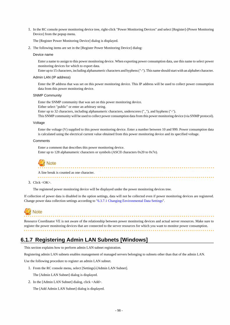
1. In the RC console power monitoring device tree, right-click "Power Monitoring Devices" and select [Register]-[Power MonitoringDevice] from the popup menu.
The [Register Power Monitoring Device] dialog is displayed.
2. The following items are set in the [Register Power Monitoring Device] dialog:
Device name
Enter a name to assign to this power monitoring device. When exporting power consumption data, use this name to select powermonitoring devices for which to export data.Enter up to 15 characters, including alphanumeric characters and hyphens ("-"). This name should start with an alphabet character.
Admin LAN (IP address)
Enter the IP address that was set on this power monitoring device. This IP address will be used to collect power consumptiondata from this power monitoring device.
SNMP Community
Enter the SNMP community that was set on this power monitoring device.Either select "public" or enter an arbitrary string.Enter up to 32 characters, including alphanumeric characters, underscores ("_"), and hyphens ("-").This SNMP community will be used to collect power consumption data from this power monitoring device (via SNMP protocol).
Voltage
Enter the voltage (V) supplied to this power monitoring device. Enter a number between 10 and 999. Power consumption datais calculated using the electrical current value obtained from this power monitoring device and its specified voltage.
Comments
Enter a comment that describes this power monitoring device.Enter up to 128 alphanumeric characters or symbols (ASCII characters 0x20 to 0x7e).
Note
A line break is counted as one character.
3. Click <OK>.
The registered power monitoring device will be displayed under the power monitoring devices tree.
If collection of power data is disabled in the option settings, data will not be collected even if power monitoring devices are registered.Change power data collection settings according to "6.3.7.1 Changing Environmental Data Settings".
Note
Resource Coordinator VE is not aware of the relationship between power monitoring devices and actual server resources. Make sure toregister the power monitoring devices that are connected to the server resources for which you want to monitor power consumption.
6.1.7 Registering Admin LAN Subnets [Windows]This section explains how to perform admin LAN subnet registration.
Registering admin LAN subnets enables management of managed servers belonging to subnets other than that of the admin LAN.
Use the following procedure to register an admin LAN subnet.
1. From the RC console menu, select [Settings]-[Admin LAN Subnet].
The [Admin LAN Subnet] dialog is displayed.
2. In the [Admin LAN Subnet] dialog, click <Add>.
The [Add Admin LAN Subnet] dialog is displayed.
- 98 -

3. In the [Add Admin LAN Subnet] dialog, set the following items.
Subnet name
Set the subnet name for registration.Enter up to 16 characters, including alphanumeric characters, underscores ("_"), hyphens ("-"), or periods ("."). This name shouldstart with an alphabet character.
Network address
Configure the network address of the subnet used as the admin LAN.Enter valid values for the network address.
Subnet mask
Enter valid values for the subnet mask.
Gateway
Enter the settings for the gateway used for communication with the admin server on the admin LAN.
4. Click <OK>.
Information
When registering an admin LAN subnet for the first time, change the simplified DHCP service for Resource Coordinator VE to theWindows standard DHCP Server.Resource Coordinator VE takes exclusive possession of the Windows standard DHCP Server.
Note
- It is necessary to perform network settings for each admin LAN subnet so that managed servers belonging to subnets other than theadmin LAN can communicate with the admin server.For details on how to configure the network settings, refer to "3.6 Configuring the Network Environment".
- In a clustered manager configuration, when registering an admin LAN subnet for the first time, perform "Settings for Clustered ManagerConfigurations".
Settings for Clustered Manager Configurations
The following configuration is necessary only when registering an admin LAN subnet for the first time.
Information
When configuring a cluster system in an environment that already has an admin LAN registered, perform steps 5. to 10. and 13.
1. Allocate the shared disk to the primary node.
In the Failover Cluster Management tree, right-click [Services and Applications]-[RC-manager], and select [Move this service orapplication to another node]-[1 - Move to node node_name].The name of the primary node is displayed in node_name.
2. Delete the registry replication settings from the following "Services and Applications" of the manager.
Based on the following table, delete registry replication for the resources.
- For x64 architectures
- 99 -
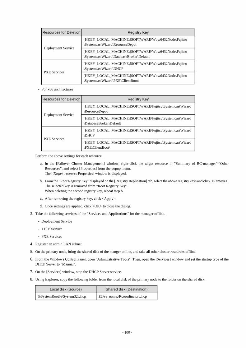
Resources for Deletion Registry Key
Deployment Service
[HKEY_LOCAL_MACHINE\]SOFTWARE\Wow6432Node\Fujitsu\SystemcastWizard\ResourceDepot
[HKEY_LOCAL_MACHINE\]SOFTWARE\Wow6432Node\Fujitsu\SystemcastWizard\DatabaseBroker\Default
PXE Services
[HKEY_LOCAL_MACHINE\]SOFTWARE\Wow6432Node\Fujitsu\SystemcastWizard\DHCP
[HKEY_LOCAL_MACHINE\]SOFTWARE\Wow6432Node\Fujitsu\SystemcastWizard\PXE\ClientBoot\
- For x86 architectures
Resources for Deletion Registry Key
Deployment Service
[HKEY_LOCAL_MACHINE\]SOFTWARE\Fujitsu\SystemcastWizard\ResourceDepot
[HKEY_LOCAL_MACHINE\]SOFTWARE\Fujitsu\SystemcastWizard\DatabaseBroker\Default
PXE Services
[HKEY_LOCAL_MACHINE\]SOFTWARE\Fujitsu\SystemcastWizard\DHCP
[HKEY_LOCAL_MACHINE\]SOFTWARE\Fujitsu\SystemcastWizard\PXE\ClientBoot\
Perform the above settings for each resource.
a. In the [Failover Cluster Management] window, right-click the target resource in "Summary of RC-manager"-"OtherResources", and select [Properties] from the popup menu.The [Target_resource Properties] window is displayed.
b. From the "Root Registry Key" displayed on the [Registry Replication] tab, select the above registry keys and click <Remove>.The selected key is removed from "Root Registry Key".When deleting the second registry key, repeat step b.
c. After removing the registry key, click <Apply>.
d. Once settings are applied, click <OK> to close the dialog.
3. Take the following services of the "Services and Applications" for the manager offline.
- Deployment Service
- TFTP Service
- PXE Services
4. Register an admin LAN subnet.
5. On the primary node, bring the shared disk of the manger online, and take all other cluster resources offline.
6. From the Windows Control Panel, open "Administrative Tools". Then, open the [Services] window and set the startup type of theDHCP Server to "Manual".
7. On the [Services] window, stop the DHCP Server service.
8. Using Explorer, copy the following folder from the local disk of the primary node to the folder on the shared disk.
Local disk (Source) Shared disk (Destination)
%SystemRoot%\System32\dhcp Drive_name:\Rcoordinator\dhcp
- 100 -

Example
When the OS has been installed on the C drive, it is %SystemRoot%C:\Windows.
9. Configure access rights for the folder for the DHCP Server that was copied to the shared disk. Run the following command fromthe command prompt on the primary node.
>cacls Drive_name:\RCoordinator\dhcp /T /P "NT AUTHORITY\SYSTEM:F" "BUILTIN\Administrators:F" "NT SERVICE\DHCPServer:F" <RETURN>
10. Add the DHCP Server to "Services and Applications" for the manager.
a. Right-click [Services and Applications]-[RC-manager], and select [Add a resource]-[Other Resources]-[1 - Add a DHCPService] from the displayed menu.A "New DHCP Service" will be created in the "DHCP Service" in "Summary of RC-manager".
b. Right-click the "New DHCP Service", and select [Properties] from the popup menu.The [New DHCP Service Properties] window is displayed.
c. Change the "Resource Name" on the [General] tab, and set the paths given in the following table.
Item Values to set in the dialog
Database path Drive_name:\Rcoordinator\dhcp
Monitoring file path Drive_name:\Rcoordinator\dhcp
Backup path Drive_name:\Rcoordinator\dhcp\backup\
After making the settings, click <Apply>.
From here the explanation is made assuming that "Resource Name" was set as "DHCP Server".
d. On the "Resource" of the [Dependencies] tab, select the following name, select AND from "AND/OR", and click <Apply>.
- Shared disk
- Network name
- Admin LAN (IP address)
e. Once settings are applied, click <OK>.
11. Configure the registry replication settings from the following "Services and Applications" of the manager.
Following the table in step 2., set replication of the registry of the resource.
Perform the following procedure for each resource.
a. In the [Failover Cluster Management] window, right-click the target resource in "Summary of RC-manager"-"OtherResources", and select [Properties] from the popup menu.The [Target_resource Properties] window is displayed.
b. In the [Registry Replication] tab, click <Add>.The [Registry Key] dialog is displayed.
c. Configure the registry key deleted in 2. in "Root registry key" and click <OK>.
When configuring the second registry key as well, repeat steps b. to c.
d. After completing registry key settings, click <Apply>.
e. Once settings are applied, click <OK> to close the dialog.
12. Configure the dependencies of the resources under the "Services and Applications".
Configure the resource dependency based on the following table.
If some resources have been configured, select AND from "AND/OR" and add the dependent resource.
- 101 -

Resource for Configuration Dependent Resource
PXE Services DHCP Server
13. Restart the manager.
In the Failover Cluster Management tree, right-click [Services and Applications]-[RC-manager], and select [Bring this service orapplication online] from the displayed menu.
6.1.8 Registering ETERNUS SF Storage CruiserThis section explains how to register ETERNUS SF Storage Cruiser.
Registering ETERNUS SF Storage Cruiser enables server switchover integrated with Fibre Channel switch zoning using ESC and hostaffinity reconfiguration on storage devices.
ETERNUS SF Storage Cruiser can be registered using the rcxadm storagemgr register command.For details on the rcxadm storagemgr register command, refer to "5.9 rcxadm storagemgr" of the "ServerView Resource Coordinator VECommand Reference".
6.2 Configuring the Operating Environment of Managed ServersThis section explains how to install software to the registered managed servers and set up their operating environment.
Figure 6.3 Procedure for Setting up Operating Environments
*1: HBA address rename and VIOM cannot be used together within the same chassis. I/O virtualization settings for all the servers mountedin one chassis must be made using either HBA address rename or VIOM.*2: These settings can be omitted for resources that have already been installed or registered.
6.2.1 Configuring VLANs on LAN SwitchesOn managed LAN switch blades, VLANs should be set on both internal ports (those connected to network interfaces on managed servers)and external ports (those connected to external, adjacent LAN switches).
- 102 -

Note
VLANs cannot be configured on PRIMERGY BX 900 and BX 400 LAN switch blades operating in IBP mode.
6.2.1.1 Configuring VLANs on external portsUse the following procedure to configure VLANs on a LAN switch blade's external ports.
1. In the RC console server resource tree, right-click the target LAN switch blade, and select [Modify]-[Network Settings] from thepopup menu.
The [VLAN Settings] dialog is displayed.
2. In the [VLAN Settings] dialog, set the following items.
VLAN
Specify the VLAN ID to assign to a LAN switch blade port.
Adding a new VLAN ID
a. Under VLAN, select "Create new".
b. Enter a VLAN ID number.Refer to the LAN switch's manual for details on VLAN IDs.
Modifying an existing VLAN ID
a. Under VLAN, select "Change".
b. Select a VLAN ID.
Port List
Under Port Number, select the VLAN Type ("Untagged" or "Tagged") to be used by each port.
3. Click <OK>.
6.2.1.2 Configuring VLANs on internal portsUse the following procedure to configure VLANs on a LAN switch blade's internal ports.
1. In the RC console server resource tree, right-click the target server (or the physical OS or VM host on the server), and select [Modify]-[Network Settings] from the popup menu.
The [Network Settings] dialog is displayed.
2. In the [Network Settings] dialog, select the index of the network interface for which to assign a VLAN ID, and click <Setting>.
The [VLAN Configuration] dialog is displayed.
3. In the [VLAN Configuration] dialog, set the following items and click <OK>.
Port VLAN
VLAN ID
Enter the VLAN ID to assign to the LAN switch blade port that is connected to the network interface selected in step 2.
Tagged VLAN
VLAN ID
Enter the tagged VLAN ID(s) to assign to the LAN switch blade port that is connected to the network interface selected instep 2.Multiple VLAN IDs can be entered by separating them with commas (",").
- 103 -

Note that the VLAN settings are not applied onto the LAN switch blade at this stage. To configure VLANs for multiple networkinterfaces, repeat steps 2 and 3.
4. Confirm the configuration set in the [Network Settings] dialog and click <OK>.
VLAN settings are applied to the related LAN switch blade.
Note
The VLAN configuration of a registered LAN switch blade should be set from the RC console instead of the LAN switch's own Web-based and command-based interfaces.
6.2.2 Configuring HBA address renameUse the following procedure to configure HBA address rename settings.The HBA address rename function allows the admin server to control the WWNs set on a managed server's HBAs. During maintenanceor switchover operations, a replacement server (or HBA) can inherit the WWN configuration set on a replaced server (or HBA). With thisfeature, the traditionally necessary re-configuration of storage devices is no longer required.Use of the HBA address rename function requires registering specific settings for each managed server in advance.
Note
- The HBA address rename function is not available if ServerView Deployment Manager is used on the admin LAN. For details, referto "Appendix J Co-Existence with ServerView Deployment Manager".
- For servers which already have server switchover configured, when configuring or changing HBA address rename, the followingconditions must be met:
- Primary servers with HBA address rename configured
- Spare servers with the server switchover method HBA address rename configured
For any servers that do not meet these conditions, cancel any existing recovery settings before enabling the HBA address renamefunction on a server.
- HBA address rename and VIOM cannot be used together within the same chassis.
- For PRIMERGY Partition Model servers, FC cards which are targeted by HBA address rename setup cannot use PHP feature.Restarting of server is required after replacing the FC card.
1. Storage settings
Refer to "3.7 Configuring the Storage Environment" to configure storage devices.When altering the configuration of a storage device already used by active servers, ensure those servers are powered off before performingany configuration changes.
2. Settings for the HBA address rename function
1. In the RC console server resource tree, right-click the target server (or the physical OS or VM host on the server), and select [Modify]-[HBA Address Rename Settings] from the popup menu.
The [HBA Address Rename Settings] dialog is displayed.
2. In the [HBA Address Rename Settings] dialog, set the following items:
WWNN
Specify the WWNN value provided by the "I/O virtualization Option".The admin server generates WWPNs automatically from the values that are input into the WWNN and the number of HBAports.
- 104 -

HBA ports
Specify the following values according to the system configuration.
- To create a single-path configuration, specify "1".
Refer to "Figure 6.4 Procedures for Single-path Configurations" for details.
- To create a multi-path configuration, specify "2".
However, it is necessary to specify "1" during installation of the operating system. Specify "2" and reconfigure HBA addressrename settings after setting up the multi-path driver.Refer to "Figure 6.5 Procedures for Multi-path Configurations" for details.
Figure 6.4 Procedures for Single-path Configurations
- 105 -
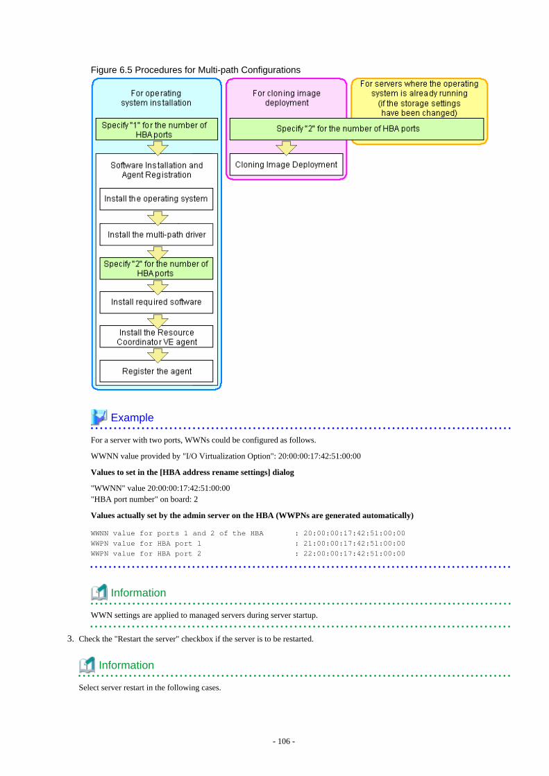
Figure 6.5 Procedures for Multi-path Configurations
Example
For a server with two ports, WWNs could be configured as follows.
WWNN value provided by "I/O Virtualization Option": 20:00:00:17:42:51:00:00
Values to set in the [HBA address rename settings] dialog
"WWNN" value 20:00:00:17:42:51:00:00"HBA port number" on board: 2
Values actually set by the admin server on the HBA (WWPNs are generated automatically)
WWNN value for ports 1 and 2 of the HBA : 20:00:00:17:42:51:00:00
WWPN value for HBA port 1 : 21:00:00:17:42:51:00:00
WWPN value for HBA port 2 : 22:00:00:17:42:51:00:00
Information
WWN settings are applied to managed servers during server startup.
3. Check the "Restart the server" checkbox if the server is to be restarted.
Information
Select server restart in the following cases.
- 106 -
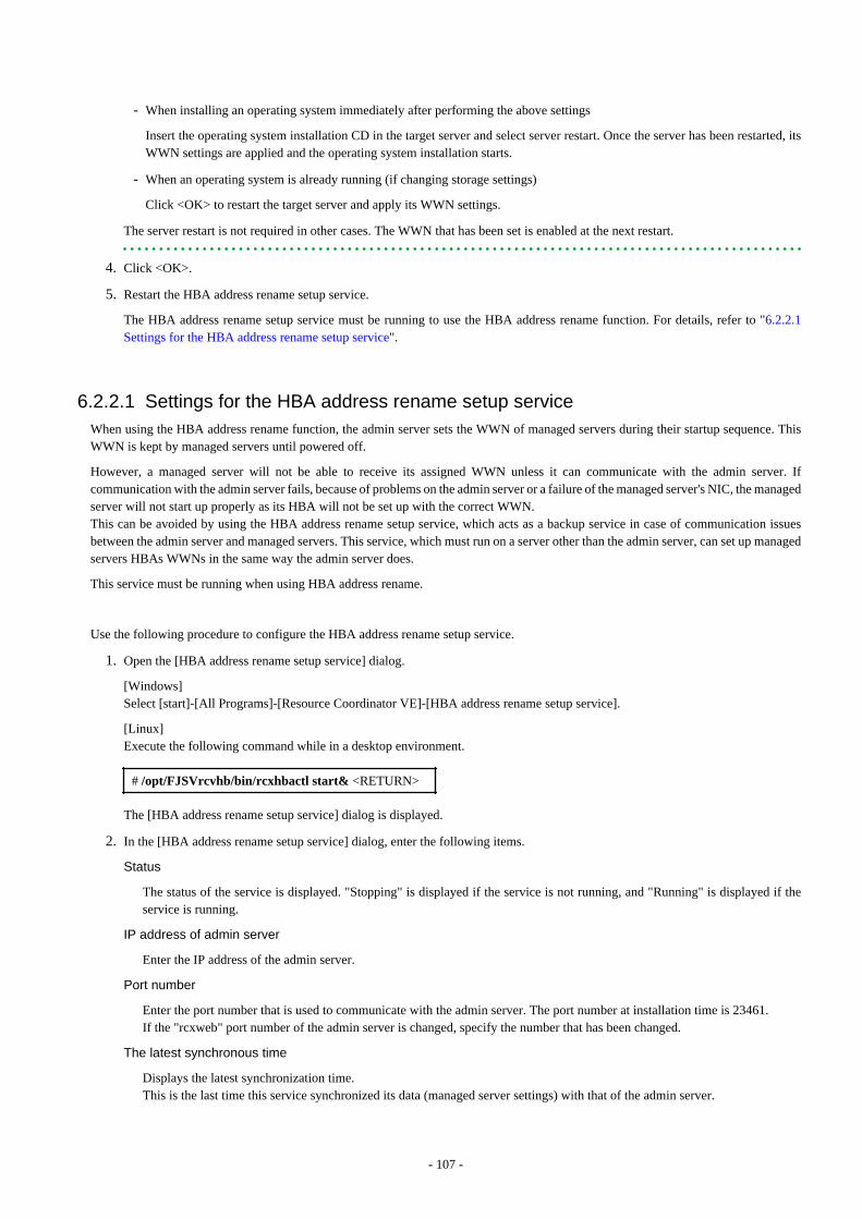
- When installing an operating system immediately after performing the above settings
Insert the operating system installation CD in the target server and select server restart. Once the server has been restarted, itsWWN settings are applied and the operating system installation starts.
- When an operating system is already running (if changing storage settings)
Click <OK> to restart the target server and apply its WWN settings.
The server restart is not required in other cases. The WWN that has been set is enabled at the next restart.
4. Click <OK>.
5. Restart the HBA address rename setup service.
The HBA address rename setup service must be running to use the HBA address rename function. For details, refer to "6.2.2.1Settings for the HBA address rename setup service".
6.2.2.1 Settings for the HBA address rename setup serviceWhen using the HBA address rename function, the admin server sets the WWN of managed servers during their startup sequence. ThisWWN is kept by managed servers until powered off.
However, a managed server will not be able to receive its assigned WWN unless it can communicate with the admin server. Ifcommunication with the admin server fails, because of problems on the admin server or a failure of the managed server's NIC, the managedserver will not start up properly as its HBA will not be set up with the correct WWN.This can be avoided by using the HBA address rename setup service, which acts as a backup service in case of communication issuesbetween the admin server and managed servers. This service, which must run on a server other than the admin server, can set up managedservers HBAs WWNs in the same way the admin server does.
This service must be running when using HBA address rename.
Use the following procedure to configure the HBA address rename setup service.
1. Open the [HBA address rename setup service] dialog.
[Windows]Select [start]-[All Programs]-[Resource Coordinator VE]-[HBA address rename setup service].
[Linux]Execute the following command while in a desktop environment.
# /opt/FJSVrcvhb/bin/rcxhbactl start& <RETURN>
The [HBA address rename setup service] dialog is displayed.
2. In the [HBA address rename setup service] dialog, enter the following items.
Status
The status of the service is displayed. "Stopping" is displayed if the service is not running, and "Running" is displayed if theservice is running.
IP address of admin server
Enter the IP address of the admin server.
Port number
Enter the port number that is used to communicate with the admin server. The port number at installation time is 23461.If the "rcxweb" port number of the admin server is changed, specify the number that has been changed.
The latest synchronous time
Displays the latest synchronization time.This is the last time this service synchronized its data (managed server settings) with that of the admin server.
- 107 -
3. To start this service, click <Run>.To stop this service, click <Stop>.To cancel, click <Cancel>.
To verify that this service is running properly, power off the admin server and confirm that managed servers can still start up normally.
Note
The following remarks apply to this service.
- Keep it running at all times.
- Start it on only one server for each admin server.
- OS administrator privileges are required to start and stop this service.
- Not operate it on the server where the manager is installed.
[Windows]
- In a clustered Manager configuration, this service can be run on the standby node. In this case, configure the startup settings followingthe procedure in the Manager Cluster Operation Settings.After performing settings for this service following the procedure for cluster operation settings, it is not necessary to perform the aboveprocedure for starting and stopping.For details, refer to "Appendix B Manager Cluster Operation Settings and Deletion" in the "ServerView Resource Coordinator VEInstallation Guide".
[Linux]
- In a clustered Manager configuration, this service can be run on the standby node. In this case, the above procedure should be skippedas configuration and control of the HBA address rename setup service is handled during setup of the cluster system.For details, refer to "Appendix B Manager Cluster Operation Settings and Deletion" in the "ServerView Resource Coordinator VEInstallation Guide".
6.2.3 WWN Settings for ETERNUS SF Storage Cruiser IntegrationThis section explains how to configure WWN settings for integration with ETERNUS SF Storage Cruiser.Specifying HBA WWNs, storage WWNs, and AffinityGroup for ETERNUS SE Storage Cruiser enables configuration of the zoningsettings of Fibre Channel switches and storage host affinity. When performing switchover on managed servers, using the WWN settingsenables the admin server to automatically change settings of storage devices.Use of this function requires registration of specific settings for ETERNUS SF Storage Cruiser in advance. Fibre Channel Switches andstorage units connected to managed servers must be registered on ESC.
Note
- WWN settings for servers and HBAs are not performed by this function.
- Configuration cannot be performed for managed servers which are configured as spare servers or are used as spare servers.
Use the following procedure to configure the WWN settings.
When changing the current WWN information, configure the new WWN information after deleting Fibre Channel Switch zoning andstorage unit host affinity in the currently configured WWN information.
1. In the RC console server resource tree, right-click the target physical server, and select [Modify]-[WWN Settings] from the popupmenu.The [WWN Settings] dialog is displayed.
2. In the [WWN Settings] dialog, set the following items:
HBA Port Number
Select the following values according to the system configuration.
- 108 -

- When creating a single-path configuration, select "1".
- When creating a multi-path configuration, select the number of multi-paths.However, it is necessary to select "1" during installation of the operating system. Select the number of paths and reconfigureHBA address rename settings after setting up the multi-path driver.
Portn WWPN
Enter or select the WWPN of an HBA collected from physical servers.When using a multi-path configuration, enter the values to match the order of the HBAs and the corresponding CAs of servers,based on the values in "3.3.4 Settings for ETERNUS SF Storage Cruiser Integration".
Target CA
Select WWPNs of storage CA and AffinityGroup.Select hyphens ("-") to keep spare servers inactive.Also, select a hyphen ("-") when deleting Fibre Channel Switch zoning and storage unit host affinity in the configured WWNinformation.
3. Click <OK>.
Perform configuration or deletion of Fibre Channel Switch zoning and storage unit host affinity based on the configured WWNinformation. When the target operation server is registered on ESC, the status should be as below:
- Configuration
The server should be turned on
- Delete
The server should be turned off
When configuration and deletion of Fibre Channel Switch zoning and storage unit host affinity have been already executed, nooperations will be performed on the devices.
Note
- For WWPN value specification, check that the value does not overlap with the WWPN used for HBA address rename or VIOM. Ifthe same WWPN is used, there is a chance data on storage units will be damaged.
- When configuration or deletion of Fibre Channel switches or storage units performed, a warning dialog is displayed. Make sure thatthere are no problems in the settings, then click <OK>.
- If the target CA is not displayed, confirm the status of the following settings:
- ESC is correctly registered on Resource Coordinator VE.
- Fibre Channel switches and storage units are correctly registered.
- Only one access path is configured on ESC for each CA of an HBA.
6.2.4 Software Installation and Agent RegistrationUse the following procedure to install required software and register a server agent.
After agent registration, the physical OS or VM host on which the agent was installed will be displayed in the server resource tree. Usually,a server agent is automatically registered during server registration. In that case, this procedure can be skipped.
It is not necessary to re-install an already-setup operating system, required software, or agent. Simply skip the steps that were alreadyperformed.
1. Install the operating system
a. Install the operating system on the managed server.
- 109 -

b. Set up the admin LAN.
Set the admin LAN IP address that was chosen for this server in "3.2.2 IP Addresses (Admin LAN)", as well as itscorresponding network mask and default gateway.
Using storage devices in multi-path configurations
- Install a multi-path driver on a physical OS and VM hosts. For VM hosts, use the one provided by default by either the operatingsystem or virtualization software, when one is available.
- When using SAN boot together with the HBA address rename function, the number of paths to be used should be set to the"HBA ports" option of the HBA address rename function (refer to "2. Settings for the HBA address rename function" of "6.2.2Configuring HBA address rename").The server is automatically restarted using a multi-path configuration.
- When using SAN boot together with VIOM, follow the procedure described in "6.1.1.1 Registering VIOM Server Profiles" toconfigure server profiles on the Web interface of ServerView Virtual-IO Manager.After configuration, the server will be started using a multi-path configuration.
- When using SAN boot together with ESC, follow the procedure described in "6.2.3 WWN Settings for ETERNUS SF StorageCruiser Integration" and set the path name for HBA, WWNs of each HBA and the target CA, and Affinity Group. Also, correctthe settings of the OS and OBP for multi-path use.After configuration, the server will be started using a multi-path configuration.
Note
After configuration of agents, the server name (computer name for [Windows/Hyper-V] or a system node name for [Linux/Solaris/VMware/Xen]) defined during OS installation should be set according to the following guidelines.
[Windows/Hyper-V]Enter up to 63 characters, including alphanumeric characters, underscores ("_"), or hyphens ("-").The string cannot be composed solely of numbers.
[Linux/VMware/Xen]Enter up to 64 characters, including alphanumeric characters as well as the following symbols.
"%", "+", ",", "-", ".", "/", ":", "=", "@", "_", "~"
[Solaris]Enter up to 24 characters, including alphanumeric characters, underscores ("_"), and hyphens ("-"). This name should start with analphabet character.
As the computer name [Windows] or the system node name [Linux/VMware] is also used as the server's host name, it is recommendedto use only the characters prescribed by RFC (Request For Comment) 952:
- Alphanumeric characters
- Hyphens, ("-")
- Periods, (".") [Linux]
It is recommended not to use duplicate names for physical OS's, VM hosts and VM guests. If duplicated names are used, thoseresources cannot be managed from the command-line.
2. Install required software
Install the software packages that are required for a managed server.For information on required software, refer to "1.1.2.2 Required Software" of the "ServerView Resource Coordinator VE InstallationGuide".
- 110 -

3. Install the Resource Coordinator VE agent
Refer to "2.2 Agent Installation" of the "ServerView Resource Coordinator VE Installation Guide".
4. Register the agent
Register the agent from the RC console while the target server is running.
a. In the RC console server resource tree, right-click the target server, and select [Register]-[Agent] from the popup menu.
The [Register Agent] dialog is displayed.
b. Select the Server OS category (physical OS or VM host).
- For a Physical OS
Select "Windows/Linux".
- For a VM host
Select "VM Host", and enter the VM host login account information.This login account information will be used by Resource Coordinator VE to control and communicate with the registeredVM host.
- For SPARC Enterprise servers
For a Physical OSSelect "Solaris".
For a VM hostSelect "Solaris Containers", and enter the VM host login account information.This login account information will be used by Resource Coordinator VE to control and communicate with the registeredVM host.
User name
Enter the user name to log in to the VM host. Specify a user name that has VM host administrator authority.
Password
Enter the password of the user to log in to the VM host.
c. Click <OK>.
The admin server starts to monitor and display server information obtained from the agent.
Note
- If a managed server whose agent was registered appears as "unknown" on the server resource tree, refer to "15.3 "unknown" ServerStatus" in the "ServerView Resource Coordinator VE Operation Guide" to resolve any issue that this server may be experiencing.
- When an agent is registered on a VM host, all VM guests running on that VM host are also registered automatically. Whenever a VMguest is created, modified, deleted, or moved on a registered VM host, the changes are automatically updated in the server resourcetree.
The VM guest name displayed in the RC console is either the VM name defined in its server virtualization software or the hostnamedefined in the guest OS.
The timing at which the hostname of a guest OS is detected and displayed varies according its server virtualization software. Fordetails, refer to "A.3 Functional Differences between Products".
- When performing system image backup or cloning image collection, it is necessary to either reboot the server or restart its "Relatedservices" (explained in the "5.2 Agent" section) after server registration.For information on re-starting agents, refer to the "5.2 Agent" section.
- A server running a VM host can still be registered as a physical OS if its selected Server OS category is set to "Windows/Linux". AVM host server that was mistakenly registered as a physical OS should be deleted and re-registered as a VM host.
- 111 -

6.2.5 Cloning Image DeploymentFor the second and subsequent servers, operating systems are created using the cloning image collected from the first server.
Refer to "Chapter 8 Cloning [Windows/Linux]".
6.2.6 Configuring Monitoring InformationUse the following procedure to configure the monitoring information.
1. In the RC console server resource tree, right-click the target physical OS and the VM hosts, and select [Modify]-[Monitoring Settings]from the popup menu.
The [Configuring monitoring settings] dialog is displayed.
2. In the [Configuring monitoring settings] dialog, set the following items:
"Enable ping monitoring" checkbox
When using the ping command to monitor the admin LAN for the target physical OS or the VM host, and recovery for the errordetection is enabled, select the checkboxes.
Information
- When performing these settings, use ping monitoring if the server status becomes "unknown".
- When the following conditions are satisfied for the physical OS and the VM host for which ping monitoring is enabled,"Message number 69111" will be output to the event log and recovery triggered. For details on the above message, refer tothe "ServerView Resource Coordinator VE Messages".
The status of the primary server is "unknown"
The period with no response by the ping command is over the time-out value
The active server has been placed into maintenance mode
The power of the chassis is not OFF (when using PRIMERGY BX servers)
Note
- As this setting uses ping monitoring on the admin LAN, recovery may be triggered even when operations are beingperformed.
- With target servers, if another Resource Coordinator VE operation is being performed when recovery is triggered, recoverywill not take place and monitoring will recommence.
- If the configured recovery process occurs and restoration is not possible, monitoring of the server will be suspendedtemporarily. After that, when the status of the server becomes "normal", monitoring will recommence.
- For VMware ESXi, this function is not supported.
Timeout(sec)
The time-out period for ping monitoring should be set as a value between 5 and 3,600 seconds.One of conditions for recovery is that the amount of time for which there is no response to the "ping" command exceeds thespecified time-out value.
Recovery method
Select a recovery operation from the following:
- Reboot
Perform reboot.
- 112 -
- Reboot (Forced)
Perform forced reboot.
- Switchover (*1)
Perform a switchover operation based on the spare server settings.
- Reboot+Switchover (*1)
First, perform reboot.Reboot operations are only performed the number of times specified in the Number of reboots, and recovery operations endif it is recovered during the reboot cycle.Perform switchover if recovery is not successful even after rebooting the specified number of times.If a spare server has not been set only rebooting will take place.
- Reboot(Forced)+Switchover (*1)
First, perform forced reboot.Forced reboot operations are performed only the number of times specified in the Number of reboots, and recovery operationsend if it is recovered during the reboot cycle.Perform switchover if recovery is not successful even after forced rebooting the specified number of times.If a spare server has not been set only forced rebooting will take place.
Number of reboots
Specify the number of reboots or forced reboots as a number between one and three. When specifying twice or more, recoverywill not be implemented when restoring.
3. Click <OK>.
*1: Cannot be selected for PRIMERGY Partition Models.
6.3 Modifying SettingsThis section explains how to change settings for the admin server or resources registered on the admin server.
6.3.1 Changing Admin Server SettingsThis section explains how to change the settings for the admin server.
6.3.1.1 Changing Admin IP AddressesUse the following procedure to change the IP address used on the admin LAN by the admin server.
1. Log on to the admin server as the administrator.
2. Stop the manager.
For details, refer to "5.1 Manager".
3. Change the SNMP trap destination set for the management blade and LAN switch blades.
Set the SNMP trap destination to the new IP address of the admin server.
Note
Depending on the LAN switch blade used, setting an SNMP trap destination may restrict SNMP access to that switch blade.In a clustered manager configuration, set the physical IP addresses of both the primary and secondary nodes as SNMP trapdestinations.If the LAN switch blade is set to only grant access from known IP addresses, be sure to give permissions to the physical IP addressesof both the primary and secondary cluster nodes, as is done with trap destination settings.For details, refer to the manual of the LAN switch blade to be used.
- 113 -

4. Change the IP address set within the operating system.
Change the IP address following the instructions given in the operating system's manual.If the admin LAN has been made redundant, change the admin IP address set in the following tools or products.
- PRIMECLUSTER GLS
- BACS
- Intel PROSet
Refer to the manual of each product for usage details.
In a clustered manager configuration, change the cluster IP address according to the instructions given in "Changing the IP Addressof a Clustered Manager".
5. Change the IP address registered as the manager's admin IP address.
Use the rcxadm mgrctl modify command to set a new IP address.
[Windows]
>"Installation_folder\Manager\bin\rcxadm" mgrctl modify -ip IP_address <RETURN>
[Linux]
# /opt/FJSVrcvmr/bin/rcxadm mgrctl modify -ip IP_address <RETURN>
In a clustered manager configuration, for details on how to change the admin IP address registered for the manager, refer to"Registering the Admin IP Address of a Clustered Manager".
6. Log in to the admin server with an OS administrator account.
7. Change ServerView Agent settings on the managed server.
Change the SNMP trap destination of the ServerView Agent. Refer to the ServerView Agent manual for details on changing SNMPtrap settings.
8. Stop the agents on managed servers. [Windows/Hyper-V] [Linux/Xen]
For details on how to stop agents, refer to "5.2 Agent".
9. Change Agent settings. [Windows/Hyper-V] [Linux/Xen]
Use the rcxadm mgrctl modify command to set the new manager IP address.
[Windows/Hyper-V]
>"Installation_folder\Agent\bin\rcxadm" agtctl modify -manager IP_address <RETURN>
[Linux/Xen]
# /opt/FJSVrcxat/bin/rcxadm agtctl modify -manager IP_address <RETURN>
10. Restart the agents on managed servers. [Windows/Hyper-V] [Linux/Xen]
For details on how to restart agents, refer to "5.2 Agent".
Repeat steps 6 to 11 for each managed server on which an agent is running.
11. Restart the manager.
For details on how to restart the manager, refer to "5.1 Manager".
12. Re-configure the HBA address rename setup service.
When using the HBA address rename function, change the IP address of the admin server that is set for the HBA address renamesetup service according to "6.2.2.1 Settings for the HBA address rename setup service".
- 114 -

13. Back up managed servers.
If system image backups have already been collected, it is recommended to update those images in order to reflect the changes madeabove. For details on system image backup, refer to "8.2 Backup" in the "ServerView Resource Coordinator VE Operation Guide".
System images backed up before changing the admin IP address of the admin server cannot be restored anymore after the change.It is recommended to delete all system images collected before change, unless those images are specifically needed.
14. Re-collect cloning images. [Windows/Linux]
If cloning images have already been collected, it is recommended to update those images to reflect the changed made above. Fordetails on cloning image collection, refer to "8.2 Collecting a Cloning Image".
Cloning images collected before changing the admin IP address of the admin server cannot be deployed anymore after the change.It is recommended to delete all cloning images collected before change, unless those images are specifically needed.
Note
- IP addresses belonging to registered admin LAN subnets cannot be changed.
- When a managed server belongs to the same subnet as the admin server, either delete the managed server or manually changethe admin IP address of the managed server. Without changing the IP address of the managed server, it is not possible to registerthe information of the subnet the managed server belongs to, or change the information of the subnet.
Changing the IP Address of a Clustered Manager
In a clustered manager configuration, use the following procedure to change the IP address set within the operating system.
[Windows]Change the IP address using the [Failover Cluster Management] window.
[Linux]
1. Stop the manager's cluster service.
Stop the manager's cluster service from the cluster administration view (Cluster Admin).
2. Log in to the admin server's primary node.
Log in to the operating system of the admin server's primary node with administration privileges.
3. Mount the shared disk on the primary node.
Mount the admin server's shared disk on the primary node.
4. Change the logical IP address.
Release PRIMECLUSTER GLS virtual interface settings from the PRIMECLUSTER resource, then change the PRIMECLUSTERGLS configuration.
For details, refer to the PRIMECLUSTER Global Link Services manual.
5. Activate the logical IP address.
Use the PRIMECLUSTER GLS command-line to activate the logical IP address.
For details, refer to the PRIMECLUSTER Global Link Services manual.
Registering the Admin IP Address of a Clustered Manager
In a clustered manager configuration, use the following procedure to register an IP address as the manager's admin LAN IP address.
[Windows]
- 115 -

1. Cancel registry replication settings.
On the primary node, bring online the shared disk and IP address, and take all other resources offline.Next, remove the following registry key from the registry replication settings set for the "PXE Services" cluster resource.
- For x64 architectures
SOFTWARE\Wow6432Node\Fujitsu\SystemcastWizard\DHCP
- For x86 architectures
SOFTWARE\Fujitsu\SystemcastWizard\DHCP
Use the following procedure to remove the registry key.
a. In the [Failover Cluster Management] window, right-click the "PXE Services" resource in "Summary of RC-manager"-"OtherResources", and select [Properties] from the popup menu.
The [PXE Services Properties] window is displayed.
b. In the [Registry Replication] tab, select the above registry key and click <Remove>.
The selected key is removed from the "Root registry key" list.
c. After removing the registry key, click <Apply>.
d. Once settings are applied, click <OK> to close the dialog.
2. Change the manager IP address on the primary node.
On the primary node, use the rcxadm mgrctl modify command to set the new IP address.
>"Installation_folder\Manager\bin\rcxadm" mgrctl modify -ip IP_address <RETURN>
3. Restore registry replication settings.
Restore the registry key deleted in step 1. to the registry replication settings of the "PXE Services" resource.Use the following procedure to restore the registry key.
a. In the [Failover Cluster Management] window, right-click the "PXE Services" resource in "Summary of RC-manager"-"OtherResources", and select [Properties] from the popup menu.
The [PXE Services Properties] window is displayed.
b. In the [Registry Replication] tab, click <Add>.
The [Registry Key] dialog is displayed.
c. Configure the registry key deleted in 2. in "Root registry key" and click <OK>.
d. After completing registry key settings, click <Apply>.
e. Once settings are applied, click <OK> to close the dialog.
4. Assign the manager's shared disk and IP address to the secondary node.
In the Failover Cluster Management tree, right-click [Services and Applications]-[RC-manager], and select [Move this service orapplication to another node]-[1 - Move to node node_name].The name of the secondary node is displayed in node_name.
5. Change the manager IP address on the secondary node.
On the secondary node, use the rcxadm mgrctl modify command to set the new IP address.Use the same IP address as the one set in step 2.
6. Assign the manager's shared disk and IP address to the primary node.
In the Failover Cluster Management tree, right-click [Services and Applications]-[RC-manager], and select [Move this service orapplication to another node]-[1 - Move to node node_name].The name of the primary node is displayed in node_name.
7. On the primary node, take the manager's shared disk and IP address offline.
- 116 -
[Linux]
1. Change the IP address set for the admin LAN.
Set a new IP address on the primary node using the following command.
# /opt/FJSVrcvmr/bin/rcxadm mgrctl modify -ip IP_address <RETURN>
2. De-activate the admin server's takeover logical IP address.
Use the PRIMECLUSTER GLS command-line interface to de-activate the takeover logical IP address.
For details, refer to the PRIMECLUSTER Global Link Services manual.
3. Register the logical IP address as a PRIMECLUSTER resource.
Use the PRIMECLUSTER GLS command-line interface to register the virtual interface as a PRIMECLUSTER resource.
For details, refer to the PRIMECLUSTER Global Link Services manual.
4. Un-mount the shared disk.
Un-mount the shared disk from the primary node.
5. Log in to the admin server's secondary node.
Log in to the operating system of the admin server's secondary node with administration privileges.
6. Change the logical IP address.
Use the PRIMECLUSTER GLS command-line interface to remove virtual interface settings from the PRIMECLUSTER resource,register the resource, and change the PRIMECLUSTER GLS configuration.
For details, refer to the PRIMECLUSTER Global Link Services manual.
7. Change the cluster configuration.
Use the cluster RMS Wizard to change the GLS resource set in the cluster service of either one of the cluster nodes.
After completing the configuration, save it and execute the following operations.
- Configuration-Generate
- Configuration-Activate
8. Start the Manager's cluster service.
Use the cluster administration view (Cluster Admin) to start the Manager's cluster service.
6.3.1.2 Changing Port NumbersThis section explains how to change the ports used by the Manager services and related services of Resource Coordinator VE.
Resource Coordinator VE requires the following services to be running. When starting these services, make sure that the ports they areusing do not conflict with the ports used by other applications or services. If necessary, change the ports used by Resource CoordinatorVE services.
[Windows]
- Manager services
- Resource Coordinator Manager
- Resource Coordinator Task Manager
- Resource Coordinator Web Server (Apache)
- Resource Coordinator Sub Web Server (Mongrel)
- Resource Coordinator Sub Web Server (Mongrel2)
- Resource Coordinator DB Server (PostgreSQL)
- 117 -
- Related services
- Deployment Service
- TFTP Service
- PXE Services
- DHCP Server
[Linux]
- Manager services
- rcxmanager
- rcxtaskmgr
- rcxmongrel1
- rcxmongrel2
- rcxhttpd
- rcxdb
- Related services
- scwdepsvd
- scwpxesvd
- scwtftpd
Change the ports used by the above services if there is a possibility that they will conflict with other applications or services.For Windows operating systems, an ephemeral port may conflict with a Resource Coordinator VE service if the maximum value allowedfor ephemeral ports (5000 by default) was changed. In this case, change the port numbers used by Resource Coordinator VE services tovalues greater than the maximum ephemeral port value.
For information on how to change the ports used by ServerView Operations Manager, refer to the ServerView Operations Manager manual.The ports used for SNMP communication and server power control are defined by standard protocols and fixed at the hardware level, andthus cannot be changed.
Refer to "Appendix C Port List", for details on the ports used by Resource Coordinator VE.When using a firewall on the network, firewall settings should be updated to match the new port definitions and allow communicationsfor any modified port.
Manager services
Use the following procedure to change the admin server ports used by manager services:
1. Stop manager services.
For details, refer to "5.1 Manager".
2. Change the port numbers.
Use the rcxadm mgrctl modify command to set a new port number for a given service name.
[Windows]
>"Installation_folder\Manager\bin\rcxadm" mgrctl modify -port name=number <RETURN>
[Linux]
# /opt/FJSVrcvmr/bin/rcxadm mgrctl modify -port name=number <RETURN>
- 118 -
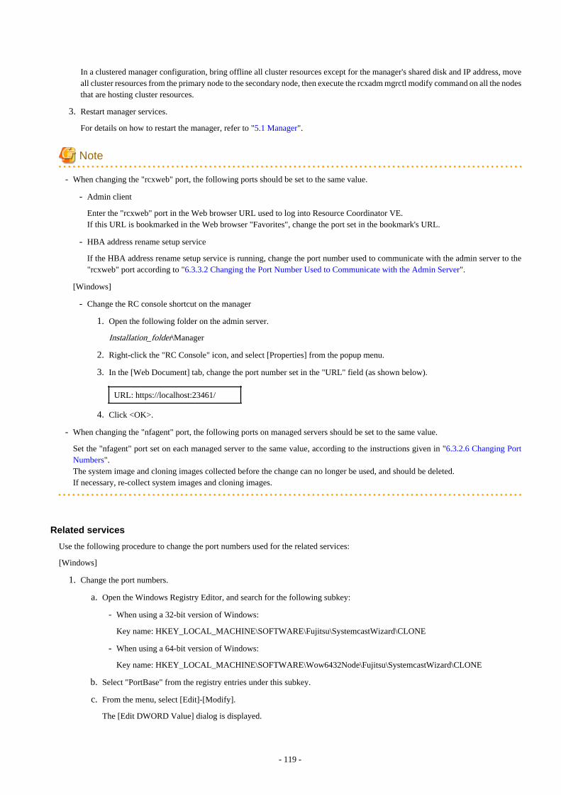
In a clustered manager configuration, bring offline all cluster resources except for the manager's shared disk and IP address, moveall cluster resources from the primary node to the secondary node, then execute the rcxadm mgrctl modify command on all the nodesthat are hosting cluster resources.
3. Restart manager services.
For details on how to restart the manager, refer to "5.1 Manager".
Note
- When changing the "rcxweb" port, the following ports should be set to the same value.
- Admin client
Enter the "rcxweb" port in the Web browser URL used to log into Resource Coordinator VE.If this URL is bookmarked in the Web browser "Favorites", change the port set in the bookmark's URL.
- HBA address rename setup service
If the HBA address rename setup service is running, change the port number used to communicate with the admin server to the"rcxweb" port according to "6.3.3.2 Changing the Port Number Used to Communicate with the Admin Server".
[Windows]
- Change the RC console shortcut on the manager
1. Open the following folder on the admin server.
Installation_folder\Manager
2. Right-click the "RC Console" icon, and select [Properties] from the popup menu.
3. In the [Web Document] tab, change the port number set in the "URL" field (as shown below).
URL: https://localhost:23461/
4. Click <OK>.
- When changing the "nfagent" port, the following ports on managed servers should be set to the same value.
Set the "nfagent" port set on each managed server to the same value, according to the instructions given in "6.3.2.6 Changing PortNumbers".The system image and cloning images collected before the change can no longer be used, and should be deleted.If necessary, re-collect system images and cloning images.
Related services
Use the following procedure to change the port numbers used for the related services:
[Windows]
1. Change the port numbers.
a. Open the Windows Registry Editor, and search for the following subkey:
- When using a 32-bit version of Windows:
Key name: HKEY_LOCAL_MACHINE\SOFTWARE\Fujitsu\SystemcastWizard\CLONE
- When using a 64-bit version of Windows:
Key name: HKEY_LOCAL_MACHINE\SOFTWARE\Wow6432Node\Fujitsu\SystemcastWizard\CLONE
b. Select "PortBase" from the registry entries under this subkey.
c. From the menu, select [Edit]-[Modify].
The [Edit DWORD Value] dialog is displayed.
- 119 -
d. Select "Decimal" and click <OK>.
This port value will define the first port of the range used by deployment services.
However, because the related services can use up to 16 port numbers, ensure that all ports included between "PortBase"(defined here) and "PortBase+15" do not conflict with any other applications or services. Moreover, be sure to set a valuelower than 65519 for "PortBase" so that the highest port number ("PortBase+15") does not exceed the largest valid portnumber (65534).In a clustered manager configuration, change port numbers on both the primary and secondary node.
2. Restart the server on which the port number has been changed.
[Linux]
1. Change the port numbers.
Edit the following file: /etc/opt/FJSVscw-common/scwconf.reg.
In PortBase (under HKEY_LOCAL_MACHINE\SOFTWARE\Fujitsu\SystemcastWizard\CLONE), set the first value of the portnumber to be used by deployment services. This value should be entered in hexadecimal format. To avoid conflicts with ephemeralports, use a value not included in the ephemeral port range defined by "net.ipv4_local_port_range".
However, as a maximum of 16 port numbers are used for image file creation and deployment, ensure that the port numbers forPortBase to PortBase +15 do not conflict with ephemeral or well-known ports.
This ensures that deployment services will use ports outside of the range defined by net.ipv4.ip_local_port_range for imageoperations.
Moreover, be sure to set a value lower than 65519 for "PortBase" so that the highest port number ("PortBase+15") does not exceedthe largest valid port number (65534).In a clustered manager configuration, change port numbers on both the primary and secondary node.
2. Restart the server on which the port number has been changed.
Information
The related services allow managed servers to boot from the network using a dedicated module stored on the admin server during backup,restore or cloning.Note that changing port numbers on the admin server alone is enough to support communication during the above image operations.Therefore, no additional configuration is required on the managed servers.
6.3.1.3 Changing the Maximum Number of System Image VersionsUse the following procedure to change the maximum number of system image versions.
1. Change the maximum number of system image versions.
2. Confirm the maximum number of system image versions.
For details, refer to "5.5 rcxadm imagemgr" of the "ServerView Resource Coordinator VE Command Reference".
Note
If the specified limit is smaller than the number of existing system image versions, older versions will not be deleted automatically. In thiscase, backing up a new system image, will only delete the oldest version.
Delete unused versions of system images manually if they are no longer necessary. For details, refer to "8.5 Deleting System Images" inthe "ServerView Resource Coordinator VE Operation Guide".
If the RC console was already opened, refresh the Web browser after changing the maximum number of system image versions.
6.3.1.4 Changing the Maximum Number of Cloning Image VersionsUse the following procedure to change the maximum number of cloning image versions.
- 120 -

1. Change the maximum number of cloning image versions.
2. Confirm the maximum number of cloning image versions.
For details, refer to "5.5 rcxadm imagemgr" of the "ServerView Resource Coordinator VE Command Reference".
Note
If the specified limit is smaller than the number of existing cloning image versions, older versions will not be deleted automatically. Inthis case, collecting a new cloning image version will require selecting a previous image version for deletion.
Delete unused image versions manually if they are no longer necessary. For details, refer to "8.5 Deleting a Cloning Image".
If the RC console was already opened, refresh the Web browser after changing the maximum number of cloning image versions.
6.3.1.5 Changing the Image Folder LocationUse the following procedure to change the location (path) of the image files folder.
1. Select the [Image List] tab in the RC console and confirm the current image list.
2. Log on to the admin server as the administrator.
3. Stop the manager.
For details, refer to "5.1 Manager".
4. Change the location of the image file storage folder.
Change the location of the image file storage folder according to the instructions given in "5.5 rcxadm imagemgr" of the "ServerViewResource Coordinator VE Command Reference".Because image files are actually copied over to the new location, this step may take some time to complete.
In a clustered manager configuration, for details on how to change the image folder location, refer to "Settings for Clustered ManagerConfigurations".
5. Restart the manager.
For details on how to restart the manager, refer to "5.1 Manager".
6. Select the [Image List] tab in the RC console and confirm the image list is same as before.
Settings for Clustered Manager Configurations
Settings differ depending on the operating system used for the manager.
[Windows]
1. Cancel registry replication settings.
Bring the manager's shared disk online, and take all other resources offline.Next, remove the following registry key from the registry replication settings set for the "Deployment Service" cluster resource.
- For x64 architectures
SOFTWARE\Wow6432Node\Fujitsu\SystemcastWizard\ResourceDepot
- For x86 architectures
SOFTWARE\Fujitsu\SystemcastWizard\ResourceDepot
Use the following procedure to remove the registry key.
a. In the [Failover Cluster Management] window, right-click the "Deployment Service" resource in "Summary of RC-manager"-"Other Resources", and select [Properties] from the popup menu.
The [Deployment Service Properties] window is displayed.
- 121 -
b. In the [Registry Replication] tab, select the above registry key and click <Remove>.
The selected key is removed from the "Root registry key" list.
c. After removing the registry key, click <Apply>.
d. Once settings are applied, click <OK> to close the dialog.
2. Change the location of the image file storage folder.
Change the location of the image file storage folder according to the instructions given in "5.5 rcxadm imagemgr" of the "ServerViewResource Coordinator VE Command Reference".Because image files are actually copied over to the new location, this step may take some time to complete.
Run the rcxadm imagemgr command from either node of the cluster resource.The new location should be a folder on the shared disk.
3. Restore registry replication settings.
Restore the registry key deleted in step 1 to the registry replication settings of the "Deployment Service" resource.Use the following procedure to restore the registry key.
a. In the [Failover Cluster Management] window, right-click the "Deployment Service" resource in "Summary of RC-manager"-"Other Resources", and select [Properties] from the popup menu.
The [Deployment Service Properties] window is displayed.
b. In the [Registry Replication] tab, click <Add>.
The [Registry Key] dialog is displayed.
c. Configure the registry key deleted in 2. in "Root registry key" and click <OK>.
d. After completing registry key settings, click <Apply>.
e. Once settings are applied, click <OK> to close the dialog.
[Linux]
1. Mount the shared disk on the primary node.
Log in to the primary node with OS administrator privileges and mount the admin server's shared disk.
2. Change the location of the image file storage directory.
Change the location of the image file storage directory according to the instructions given in "5.5 rcxadm imagemgr" of the"ServerView Resource Coordinator VE Command Reference".
Because image files are actually copied over to the new location, this step may take some time to complete.
Run the rcxadm imagemgr command on the primary node.
The new location should be a directory on the shared disk.
3. Un-mount the shared disk from the primary node.
Un-mount the shared disk (for which settings were performed in step 1) from the primary node.
6.3.1.6 Changing Admin LAN Subnets [Windows]Use the following procedure to change an admin LAN subnet.
1. From the RC console menu, select [Settings]-[Admin LAN Subnet].
The [Admin LAN Subnet] dialog is displayed.
2. Click <Change> in the [Admin LAN Subnet] dialog.
The [Change Admin LAN Subnet] dialog is displayed.
- 122 -

3. In the [Change Admin LAN Subnet] dialog, set the following items.
Subnet name
Enter up to 16 characters, including alphanumeric characters, underscores ("_"), hyphens ("-"), or periods ("."). This name shouldstart with an alphabet character.
Network address
Enter valid values for the network address.
Subnet mask
Enter valid values for the subnet mask.
Gateway
Enter the settings for the gateway used for communication with the admin server on the admin LAN.
4. Click <OK>.
Note
When changing the information for a subnet other than the one the admin server belongs to, if there is even 1 managed server belongingto the target subnet, the "Network address" and "Subnet mask" cannot be changed.When changing the "Network address" or "Subnet mask", refer to the "Modification Procedure When there are Managed Servers Belongingto Different Subnets".
Modification Procedure When there are Managed Servers Belonging to Different Subnets
When there are managed servers in the target subnet, change the network address or the subnet mask using the following procedure.
1. Register the subnet information using the new network address or subnet mask.
2. Use the following procedure to change the admin LAN IP addresses of all managed servers belonging to the subnet beforemodification.For details on how to configure these settings, refer to "6.3.2.3 Changing Admin IP Addresses".
3. Delete the subnet used before modification.
6.3.1.7 Changing the Password for the Resource Coordinator VE DatabaseUse the following procedure to change the password for the Resource Coordinator VE database:
1. Log on to the admin server as the administrator.
2. Stop the manager.
For details, refer to "5.1 Manager".
3. Change the password for the Resource Coordinator VE database.
Execute the rcxadm dbctl modify command.Enter the new password interactively.
[Windows]
>"Installation_folder\Manager\bin\rcxadm" dbctl modify -passwd <RETURN>
[Linux]
# /opt/FJSVrcvmr/bin/rcxadm dbctl modify -passwd <RETURN>
- 123 -

In a clustered manager configuration, bring offline all manager resources except for the shared disk, move all cluster resources fromthe primary node to the secondary node, then execute the rcxadm dbctl modify command on all the nodes that are hosting clusterresources.
4. Restart the manager.
For details on how to restart the manager, refer to "5.1 Manager".
6.3.2 Changing Chassis and Managed Servers SettingsThis section explains how to change the settings for the chassis and managed servers.If collecting the system images and cloning images of the managed server, collect system images and cloning images after completingchanges in the managed server settings.For details on backing up system images, refer to "8.2 Backup" in the "ServerView Resource Coordinator VE Operation Guide".For details on how to collect cloning mages, refer to "8.2 Collecting a Cloning Image".
Note
- To change VM guest settings, use the management console of the server virtualization software used.
- A managed server that has already been registered cannot be moved to a different slot.To move a managed server to a different slot, first delete the managed server, then move it to the new slot and register it again.
6.3.2.1 Changing Chassis NamesThis section explains how to change chassis names.Use the following procedure to change the name of a registered chassis.
1. In the RC console server resource tree, right-click the target chassis and select [Modify]-[Registration Settings] from the popupmenu.
The [Modify Chassis Settings] dialog is displayed.
2. In the [Modify Chassis Settings] dialog, set the following items.
Chassis name
Enter up to 10 characters, including alphanumeric characters and hyphens ("-"). This name should start with an alphabet character.
3. Click <OK>.
The chassis name is changed.
6.3.2.2 Changing Server NamesThis section explains how to change physical server names.Names of physical OS's, VM hosts and VM guests can be changed by a user with administrative authority. Once changed, new names areautomatically reflected in the RC console.
Use the following procedure to change the name of a physical server.
1. In the RC console server resource tree, right-click the target server, and select [Modify]-[Registration Settings] from the popupmenu.
The [Modify Server Settings] dialog is displayed.
- 124 -

2. In the [Modify Server Settings] dialog, set the following items.
Physical Server Name
Enter up to 15 characters, including alphanumeric characters and hyphens ("-"). This name should start with an alphabet character.
3. Click <OK>.
The server name is changed.
4. If the network parameter auto-configuration function is used in the deployment of the cloning images, the "Physical Server Name"set in the definition file must also be changed.
For details on the network parameter auto-configuration function, refer to "8.6 Network Parameter Auto-Configuration for CloningImages".
6.3.2.3 Changing Admin IP AddressesThis section explains how to change admin IP addresses.
To change the IP addresses of remote management controllers, refer to "6.3.2.5 Changing Server Management Unit ConfigurationSettings".
Chassis
Use the following procedure to change the IP address of a chassis.
1. Change the IP address of the management blade.
2. In the RC console server resource tree, right-click the target chassis and select [Modify]-[Registration Settings] from the popupmenu.
The [Modify Chassis Settings] dialog is displayed.
3. In the [Modify Chassis Settings] dialog, change the "Admin LAN (IP address)".
4. Click <OK>.
The chassis admin IP address is changed.
Managed servers
Use the following procedure to change the IP address of a managed server.However, it is still required when using the same address for both the admin and public IP address. This procedure is not required whenchanging only the public IP address of a server.
1. Log in to the admin server with an OS administrator account.
2. Change the IP address set within the operating system.
Change the IP address according to the OS manual.If the admin LAN has been made redundant, change the admin IP address set in the following tools or products.
Refer to the manual of each product for usage details.
[Windows]PRIMECLUSTER GLSBACSIntel PROSet
[Linux/Solaris]PRIMECLUSTER GLS: "NIC switching mode (Physical IP address takeover function)".
3. Restart the managed server.
- 125 -

4. In the RC console server resource tree, right-click the target server, and select [Modify]-[Registration Settings] from the popupmenu.
The [Modify Server Settings] dialog is displayed.
5. In the [Modify Server Settings] dialog, change the "Admin LAN(IP address)".
6. Click <OK>.
The admin IP address of the managed server is changed.
Note
It is not possible to change IP address settings of a managed server (primary server) with a spare server configured to a different subnetfrom the spare server.
6.3.2.4 Changing SNMP CommunitiesThis section explains how to change SNMP community settings.
- For blade servers, PRIMERGY Partition Model servers or SPARC Enterprise M4000/M5000/M8000/M9000 servers
Use the following procedure to change SNMP community used by chassis and managed servers.
1. Change the SNMP community set on the management blade, management board, or XSCF.
The new SNMP community should have Read-Write permission.For details on changing SNMP communities, refer to the manual of the management blade, management board, or XSCF.
2. Change the SNMP community set on the managed server.
Use the same name for the SNMP community of the managed server on the management blade, the management board, andthe XSCF.Follow the instructions in the ServerView Agent's manual to change the SNMP community used by a managed server.The new SNMP community should have Read-Write permission.
3. In the RC console server resource tree, right-click the target chassis and select [Modify]-[Registration Settings] from the popupmenu.
The [Modify Chassis Settings] dialog is displayed.
4. In the [Modify Chassis Settings] dialog, change the "SNMP Community".
5. Click <OK>.
The SNMP community is changed.
- For rack mount or tower servers
Use the following procedure to change the SNMP community used by PRIMERGY servers.For servers other than PRIMERGY servers, changing SNMP communities does not require any configuration change in ResourceCoordinator VE.
1. Change the SNMP community set on the managed server.
Follow the instructions in the ServerView Agent's manual to change the SNMP community used by a managed server.
2. In the RC console server resource tree, right-click the target server, and select [Modify]-[Registration Settings] from the popupmenu.
The [Modify Server Settings] dialog is displayed.
3. In the [Modify Server Settings] dialog, change the "SNMP Community".
4. Click <OK>.
The SNMP community is changed.
- 126 -

- For SPARC Enterprise servers
Use the following procedure to change SNMP community used by the Remote Management Controller.
1. Change the SNMP community set on the remote management controller (XSCF).
For details on changing SNMP communities, refer to the XSCF manuals.
2. In the RC console server resource tree, right-click the target chassis and select [Modify]-[Registration Settings] from the popupmenu.
The [Modify Chassis Settings] dialog is displayed.
3. In the [Modify Chassis Settings] dialog, change the "SNMP Community".
4. Click <OK>.
The SNMP community is changed.
6.3.2.5 Changing Server Management Unit Configuration SettingsThis section explains how to modify server management unit settings.
- For rack mount or tower servers
Use the following procedure to change remote management controller settings.
1. Change settings on the remote management controller.If the user account is changed, it should still have administrator authority.
2. In the RC console server resource tree, right-click the target server, and select [Modify]-[Registration Settings] from the popupmenu.
The [Modify Server Settings] dialog is displayed.
3. In the [Modify Server Settings] dialog, change the "Remote management controller IP Address". To modify user accountinformation, select the "Modify remote management controller login account" checkbox, and change the "User name" and"Password" of the "Remote management controller".
- For SPARC Enterprise M3000 servers
Use the following procedure to change remote management controller (XSCF) settings.
1. Change settings on the remote management controller (XSCF).If the user account is changed, it should still have administrator authority ("platadm" privileges).
2. In the RC console server resource tree, right-click the target server, and select [Modify]-[Registration Settings] from the popupmenu.
The [Modify Server Settings] dialog is displayed.
3. In the [Modify Server Settings] dialog, change the "Remote management controller (ILOM/XSCF)".To modify user account settings, select the "Modify remote management controller login account" checkbox, and change the"User name" and "Password" fields under "Remote management controller (ILOM/XSCF)".
- For SPARC Enterprise T servers
Use the following procedure to change remote management controller settings (ILOM).
1. Change settings on the remote management controller (ILOM).If the user account is changed, it should still have administrator authority ("Admin" privileges).
2. In the RC console server resource tree, right-click the target server, and select [Modify]-[Registration Settings] from the popupmenu.The [Modify Server Settings] dialog is displayed.
3. In the [Modify Server Settings] dialog, change the "Remote management controller (ILOM/XSCF)".To modify user account settings, select the "Modify remote management controller login account" checkbox, and change the"User name" and "Password" fields under "Remote management controller (ILOM/XSCF)".
- 127 -

- For PRIMERGY Partition Model servers
Use the following procedure to change remote server management settings.
1. Change the remote server management settings.If the user account is changed, it should still have administrator authority.
2. In the RC console server resource tree, right-click the target chassis and select [Modify]-[Registration Settings] from the popupmenu.
The [Modify Chassis Settings] dialog is displayed.
3. In [Modify Chassis Settings] dialog, select the "Modify remote server management login account" checkbox. Then, change the"User name" and "Password" of "Remote Server Management".
- For SPARC Enterprise M4000/M5000/M8000/M9000 servers
Use the following procedure to change remote management controller (XSCF) settings.
1. Change settings on the remote management controller (XSCF).
If the user account is changed, it should still have administrator authority ("platadm" privileges).
2. In the RC console server resource tree, right-click the target chassis and select [Modify]-[Registration Settings] from the popupmenu.
The [Modify Chassis Settings] dialog is displayed.
3. In [Modify Chassis Settings] dialog, select the "Modify remote server management login account" checkbox. Then, change the"User name" and "Password" of "Remote server management (XSCF)".
6.3.2.6 Changing Port NumbersThis section explains how to change port numbers.
When changing port numbers of the agent, the "nfagent" port of the manger must also be changed. Change this according to informationin "6.3.1.2 Changing Port Numbers".For details on port numbers, refer to "Appendix C Port List".
Use the following procedure to change the port numbers for managed servers:
1. Change the port numbers.
[Windows/Hyper-V]Use a text editor (such as Notepad) to change the following line in the Windows_system_folder\system32\drivers\etc\services file.
# service name port number/protocol name
nfagent 23458/tcp
[Linux/VMware/Xen]Use a command such as vi to change the following line in the /etc/services file.
# service name port number/protocol name
nfagent 23458/tcp
[Solaris]Use a command such as vi to change the following line in the /etc/services file.
# service name port number/protocol name
rcvat 23458/tcp
2. Restart the server on which the port number has been changed.
- 128 -

6.3.2.7 Changing VM Host Login Account InformationThis section explains how to change VM host login account information.
If the login account information (user name and password) of the VM host entered when the VM host was registered is changed on theVM host, change the login account information of the VM host that was registered in Resource Coordinator VE.
The method for changing the VM host login account is shown below.
1. In the RC console server resource tree, right-click the target VM host, and select [Modify]-[VM Host Login Account] from thepopup menu.
The [Change Login Information] dialog is displayed.
2. In the [Change Login Information] dialog, enter the login account information which was changed on the VM host.
User name
Enter the user name to log in to the VM host. Specify a user name that has VM host administrator authority.
Password
Enter the password of the user to log in to the VM host.
3. Click <OK>.
VM host login information is changed.
6.3.2.8 Changing the VLAN Settings of LAN Switch BladesThis section explains how to change LAN switch VLAN settings.The VLAN settings of the LAN switch blade ports connected to the physical servers can be reconfigured normally within ResourceCoordinator VE.Refer to "6.2.1.2 Configuring VLANs on internal ports" for details on how to configure these settings.
6.3.2.9 Changing HBA address rename SettingsThis section explains how to change the HBA address rename settings.
The WWNs and HBA ports that are set by HBA address rename can be reconfigured normally within Resource Coordinator VE.For details on how to configure these settings, refer to "6.2.2 Configuring HBA address rename".
6.3.2.10 Changing Boot OptionsThis section explains how to change boot option settings.
The boot options configured for PRIMERGY Partition Models can be changed by re-configuring them.Use the following procedure to configure the boot option settings.
1. In the RC console server resource tree, right-click the target server, and select [Modify]-[Registration Settings] from the popupmenu.
The [Modify Server Settings] dialog is displayed.
2. In the [Modify Server Settings] dialog, set the following items.
Boot option
For UEFISelect "UEFI".
For Legacy bootSelect "Legacy boot".
- 129 -

Note
Changing the boot option changes the information registered with Resource Coordinator VE.As the actual boot option will not be changed, it is necessary to change the BIOS settings when performing the change.
6.3.2.11 Changing WWN Settings for ETERNUS SF Storage Cruiser IntegrationThis section explains how to change WWN settings for integration with ETERNUS SF Storage Cruiser.
The WWN settings for ETERNUS SF Storage Cruiser integration can be changed by re-configuring them.Refer to "6.2.3 WWN Settings for ETERNUS SF Storage Cruiser Integration" for details on how to configure these settings.
6.3.3 Changing Settings for the HBA Address Rename Setup ServiceThis section explains how to change settings for the HBA address rename setup service. Such settings include the admin server IP address,the port used to communicate with the admin server, and the IP address of the HBA address rename server.
6.3.3.1 Changing the IP Address of the Admin ServerThis section explains how to change the IP address of the admin server.
When this setting is changed, the HBA address rename setup service automatically checks whether it can communicate with the new adminserver IP address.Changing this setting also requires changing the port on the admin server side beforehand.
Change the IP address of the admin server according to "6.3.1.1 Changing Admin IP Addresses", and change the admin IP address for theHBA address rename setup service according to step 12.
6.3.3.2 Changing the Port Number Used to Communicate with the Admin ServerThis section explains how to change the port used between the HBA address rename setup service and the admin server.
The HBA address rename setup service uses the "rcxweb" port to communicate with the admin server.When this setting is changed, the HBA address rename setup service automatically checks whether it can communicate with the new adminserver IP address.Changing this setting also requires changing the port on the admin server side beforehand.
Use the following procedure to change the port numbers used to communicate with the admin server:
1. Change the port number of the manager.
Change the "rcxweb" port number according to the instructions given in "6.3.1.2 Changing Port Numbers".
2. Change the port number of the HBA address rename setup service.
Refer to "6.2.2.1 Settings for the HBA address rename setup service", and change the port to the same port number.
6.3.3.3 Changing the IP Address of the HBA Address Rename ServerThis section explains how to change the IP address of the HBA address rename server.
Use the following procedure to change the IP address of the HBA address rename server.
1. Log in to the HBA address rename server with administrator authority.
2. Stop the HBA address rename setup service.
Stop the HBA address rename setup service according to "6.2.2.1 Settings for the HBA address rename setup service".
- 130 -

3. Change the IP address set within the operating system.
Change the IP address according to the OS manual.
4. Restart the HBA address rename setup service.
Restart the HBA address rename setup service according to "6.2.2.1 Settings for the HBA address rename setup service".
6.3.4 Changing VIOM Registration SettingsUse the following procedure to perform setting changes for management software (VIOM).
1. In the RC console management software tree, right-click the target chassis and select [Modify]-[Registration Settings] from thepopup menu.The [Modify Management Software(VIOM) Settings] dialog is displayed.
2. In the [Modify Management Software(VIOM) Settings] dialog, enter the following items.
User name
Enter the name of a VIOM user account.
Password
Enter the password of the above VIOM user account.
3. Click <OK>.To change registered VIOM server profiles, follow the procedure described in "6.1.1.1 Registering VIOM Server Profiles" to openthe Web interface of ServerView Virtual-IO Manager and change the settings. Changes made inside Virtual-IO Manager areautomatically reflected in Resource Coordinator VE.
6.3.5 Changing LAN Switch SettingsThis section explains how to change LAN switch settings.
6.3.5.1 Changing LAN Switch Basic SettingsThis section explains how to change LAN switch basic settings.
The following settings can be changed.
- LAN switch name (node name for management purposes)
- Admin LAN (IP address)
- User name (LAN switch blade only)
- Password (LAN switch blade only)
- Privileged password (LAN switch blade only)
- SNMP Community
Complete the changes to the settings on the target LAN switch before performing this procedure.
Use the following procedure to change LAN switch settings:
1. In the RC console server resource tree or network resource tree, right-click the target LAN switch name and select [Modify]-[Registration Settings] from the popup menu.
The [Modify LAN Switch] dialog is displayed.
2. Edit the information in the [Modify LAN Switch] dialog and click the <OK> button.
The settings for the LAN switch are changed with the entered information.
- 131 -

Note
It is possible to set the IP address of the target switch to another unregistered LAN switch. However, this will result in the ResourceCoordinator VE configuration being inconsistent with the actual network configuration.If the IP address of the target switch is set to the same address as that of another unregistered LAN switch unintentionally, change backthe target LAN switch IP address to its original value according to the instructions given in this section.If there are more than one LAN switch with inconsistent IP address configurations, delete all registered LAN switches according to "6.4.4.2Deleting LAN Switches (Non-Blade Switches)" first, then perform Discover and Register according to "6.1.4.2 Registering LAN Switches(Non-Blade Switches)".
6.3.5.2 Changing VLANs set on External LAN Switch Blade PortsVLAN types and IDs set on the external ports of a managed LAN switch blade can be changed.
Note
VLANs cannot be changed on PRIMERGY BX900/BX400 LAN switch blades operating in IBP mode.
Changing VLAN IDs
This section explains how to change VLAN IDs set on the external ports of a LAN switch.
- With Port VLANs
Use the following procedure to change VLAN IDs:
1. In the RC console server resource tree, right-click the target LAN switch blade and select [Modify]-[Network Settings] fromthe popup menu.
The [VLAN Settings] dialog is displayed.
2. In the [VLAN Settings] dialog, set the following items.
VLAN
Select "Change" and select the VLAN ID that has been changed.
Port List
Under Port Number, select the VLAN type "Untagged" to be used by each port.
3. Click <OK>.
The VLAN ID is changed.
- With Tagged VLANs
First delete the VLAN ID was set on the desired LAN switch blade port before setting the new VLAN ID.
Use the following procedure to change VLAN IDs:
1. In the RC console server resource tree, right-click the target LAN switch blade and select [Modify]-[Network Settings] fromthe popup menu.
The [VLAN Settings] dialog is displayed.
2. In the [VLAN Settings] dialog, set the following items.
VLAN
Select "Change" and select the VLAN ID that has been changed.
- 132 -

Port List
Under Port Number, select the VLAN type "None" to be used by each port.
3. Click <OK>.
The VLAN ID set for the selected LAN switch blade port is released.
4. Repeat step 1 and set the new VLAN ID in the [VLAN Settings] dialog.
VLAN
Select "Create new" or "Change" in the VLAN information and select the VLAN ID to be changed.
Port List
Under Port Number select the VLAN type "Tagged" to be used by each port.
5. Click <OK>.
The VLAN ID is changed.
Changing VLAN types
This section explains how to change the types of VLAN (port or tagged VLAN) set on the external ports of a LAN switch.
Use the following procedure to change VLAN types:
1. In the RC console server resource tree, right-click the target LAN switch blade and select [Modify]-[Network Settings] from thepopup menu.
The [VLAN Settings] dialog is displayed.
2. In the [VLAN Settings] dialog, set the following items.
VLAN
Select "Change" and select the VLAN ID that has been changed.
Port List
Under Port Number, select the VLAN type ("Untagged" or "Tagged") to be used by each port.
3. Click <OK>.
The VLAN type is changed.
Deleting VLAN IDs
This section explains how to delete VLAN IDs.
- Deleting VLAN IDs from LAN switch blades
Use the following procedure to delete VLAN IDs:
1. In the RC console server resource tree, right-click the target LAN switch blade and select [Modify]-[Network Settings] fromthe popup menu.
The [VLAN Settings] dialog is displayed.
2. In the [VLAN Settings] dialog, set the following items.
VLAN
Select "Change" and select the VLAN ID that has been changed.
3. Click <Delete>.
The VLAN ID is deleted.
- 133 -

- Deleting VLAN IDs from LAN switch ports
Use the following procedure to delete VLAN IDs:
1. In the RC console server resource tree, right-click the target LAN switch blade and select [Modify]-[Network Settings] fromthe popup menu.
The [VLAN Settings] dialog is displayed.
2. In the [VLAN Settings] dialog, set the following items.
VLAN
Select "Change" and select the VLAN ID that has been changed.
Port List
Under Port Number, select the VLAN type "None" to be used by each port.
3. Click <OK>.
The VLAN ID is deleted.
6.3.5.3 Re-discovering LAN SwitchesNewly added LAN switches can be discovered by re-executing LAN switch discovery.For details on LAN switch discovery, refer to "Discovery" in "6.1.4.2 Registering LAN Switches (Non-Blade Switches)".
6.3.6 Changing VM Management Software SettingsThis section explains how to change VM management software settings.
The following settings can be changed.
- Location
- IP address
- User name
- Password
Here the method for changing settings registered with Resource Coordinator VE is explained.
Complete re-configuration within the VM management software admin console before performing this procedure.
Use the following procedure to change VM management software settings:
1. In the RC console management software tree, right-click the management software, and select [Modify]-[Registration Settings]from the popup menu.
The [Modify Management Software(name) Settings] dialog is displayed.The name of the selected VM management software is displayed in name.
2. In the [Modify Management Software(name) Settings] dialog, enter the following items.
Location
Select the location of the VM management software registration to change.
- If VM management software is installed on the admin server
Select "Admin Server".
- Any other case
Select "Other Server".
IP address
If "Other Server" was selected, enter the IP address of the server on which VM management software is installed.
- 134 -

User name
Enter the name of a VM management software user account with administrative authority.
Password
Enter the password of the above VM management software user account.
3. Click <OK>.
VMware management software settings are changed.
6.3.7 Changing Power Monitoring Environment SettingsThis section explains how to change power monitoring environment settings.
Power environment settings include environmental data settings, collection cancel settings, and power monitoring device settings.
6.3.7.1 Changing Environmental Data SettingsUse the following procedure to change environmental data settings:
1. From the RC console menu, select [Tools]-[Options].
The [Options] dialog is displayed.
2. In the [Options] dialog, click the "Environmental Data" category title, and input the following items in the displayed area.
Data to collect
Select the "Power" checkbox, to start collecting power consumption data.
Polling interval (in minutes)
Enter the time interval of the data collection (1-6 or 10).The number of devices that can be monitored simultaneously depends on the value of this polling interval and the load put onthe admin server. The following values are guidelines.
Table 6.1 Polling interval
Polling interval Number of devices that can be monitored simultaneously
5 minutes Up to 40 devices
10 minutes Up to 60 devices
Use a polling interval of 5 minutes or longer when monitoring chassis and servers. Use a polling interval of 10 minutes if monitoringmore than 40 devices.
Data storage period
Enter storage periods for each collection rate. Data older than the configured storage period will be deleted everyday.Enlarging data storage periods reduces the number of devices that can be monitored simultaneously.Use the default storage period values when monitoring chassis and servers.
3. Click <Apply>.
The modified settings are reflected.
Note
If the "Power" checkbox under "Data to collect" is cleared, the collection of power consumption data (including the calculation of hourly,daily, and other summarized data) will not be performed anymore.
- 135 -

6.3.7.2 Cancelling Collection Settings for Power Monitoring EnvironmentsThis section explains how to cancel the collection of power consumption data.
Use the following procedure to cancel the collection of power consumption data.
1. From the RC console menu, select [Tools]-[Options].
The [Options] dialog is displayed.
2. In the [Options] dialog, click the "Environmental Data" category title, and change the following items in the displayed area.
Data to collect
Clear the "Power" checkbox.
3. Click <Apply>.
Collection of environmental data is canceled.
6.3.7.3 Changing Power Monitoring DevicesThis section explains how to change power monitoring device settings.
The following settings can be changed.
- Device name
- Admin LAN (IP address)
- SNMP Community
- Voltage
- Comment
Complete setting modifications on the actual power monitoring device before performing this procedure.
Use the following procedure to change power monitoring device settings:
1. From the RC console, right-click the power monitoring device tree, then select [Modify]-[Registration Settings] from the popupmenu.
The [Modify Power Monitoring Device] dialog is displayed.
2. Edit the items to be changed in the [Modify Power Monitoring Device] dialog and click <OK>.
The power monitoring device settings will be changed with the entered information.
6.3.8 Changing Monitoring Information SettingsThis section explains how to change and cancel monitoring information settings.
6.3.8.1 Changing Monitoring Information SettingsThis section explains how to change monitoring information settings.
The following settings can be changed.
- Enabling or disabling of ping monitoring
- Time-out
- Recovery method
- Number of reboots
Use the following procedure to change settings:
- 136 -

1. In the RC console server resource tree, right-click the target physical OS and the VM hosts, and select [Modify]-[Monitoring Settings]from the popup menu.
The [Configuring monitoring settings] dialog is displayed.
2. Edit the information in the [Configuring monitoring settings] dialog and click <OK>.
The settings for the monitoring information are changed to the entered settings.
6.3.8.2 Cancelling Monitoring Information SettingsThis section explains how to cancel monitoring information settings.
Use the following procedure to cancel the monitoring information settings:
1. In the RC console server resource tree, right-click the target physical OS and the VM hosts, and select [Modify]-[Monitoring Settings]from the popup menu.The [Configuring monitoring settings] dialog is displayed.
2. In the [Configuring monitoring settings] dialog, un-select the "Enable ping monitoring" checkbox and click <OK>.The settings for the monitoring information are cancelled.
6.4 Deleting ResourcesThis section explains how to delete resources.The managed server and the LAN switch can be registered and deleted for one resource in the same chassis.Note that operation of a server cannot be performed while the LAN switch is being registered and removed.If the operation is performed simultaneously for multiple resources, one of the following messages is displayed.In this case, wait until the current operation is completed before executing the desired operation again.
FJSVrcx:ERROR:67210: LAN_switch_name(LAN switch):is busy
or
FJSVrcx:ERROR:67210: Managed_server_name (physical server):is busy
6.4.1 Deleting ChassisThis section explains how to delete chassis.
Use the following procedure to delete the chassis.
1. In the RC console server resource tree, right-click the target chassis, and select [Delete] from the popup menu.
The [Delete Resource] dialog is displayed.
2. Click <OK>.
The target chassis is deleted from the server resource tree.
Note
If server blades and partitions within the chassis were already registered, delete these server blades and partitions before deleting the chassis.If LAN switches have been registered, delete all LAN switches before deleting the chassis.
6.4.2 Deleting Managed ServersThis section explains how to delete managed servers.
Use the following procedure to delete managed servers.
- 137 -

1. In the RC console server resource tree, right-click the target server (or the physical OS or the VM host on the server) and select[Delete] from the popup menu.
The [Delete Resource] dialog is displayed.
If a VM host is running on the server to be deleted, any VM guests running on that host are also deleted from the server resourcetree at the same time. The VM guests to be deleted appear in the [Delete Resource] dialog, so check that it is safe to delete them.
2. Click <OK>.
If a physical OS or VM host exists on the target server and HBA address rename is set, the server will be powered off when theresource is deleted. The target server is un-registered. Resource Coordinator VE does not delete the host affinity settings of storageunits or the zoning settings of Fibre Channel switches.When WWN information is configured on the target server, Resource Coordinator VE deletes the host affinity settings of storageunits and the zoning settings of Fibre Channel switches during SPARC server deletion.
When deleting a PRIMERGY BX server, PRIMERGY Partition Model servers or SPARC Enterprise M4000/M5000/M8000/M9000servers, the deleted server will still be displayed in the server resource tree as "not registered".
Information
- If HBA address rename has already been set up on the managed server, the HBA WWN is reset to the factory default.Power to the managed server is turned on temporarily when this occurs.
- VM guests can be deleted using the management console of the server virtualization software used. Doing so will automatically deletethose VM guests from Resource Coordinator VE as well.
- If the same storage device volume is to be used to operate the target server after the server has been deleted, use storage managementsoftware such as ETERNUS SF Storage Cruiser to reset the storage host affinity and fibre channel switch zoning with the factorydefault WWN.
- Any system images backed up from the target server are also deleted automatically.
- After the server has been deleted, the maintenance LED is switched OFF automatically.
- Deleting a server on which both the HBA address rename function and a VM high-availability feature (provided by the servervirtualization software used) are enabled will produce the following behavior. The server will be powered off, causing the high-availability feature to trigger its VM recovery process. To avoid interruption of hosted applications during server deletion, it isrecommended to move VM guests to another server beforehand. For more details on the high-availability features available for eachserver virtualization software, refer to "A.2 Configuration Requirements".
6.4.3 Cancelling VIOM IntegrationThis section explains how to cancel VIOM integration.
Use the following procedure to cancel VIOM integration:
1. In the RC console management software tree, right-click the target chassis, and select [Delete] from the popup menu.The [Delete Resource] dialog is displayed.
2. Click <OK>.The target management software (VIOM) is deleted.
- 138 -

To delete registered VIOM server profiles, follow the procedure described in "6.1.1.1 Registering VIOM Server Profiles" to open the Webinterface of ServerView Virtual-IO Manager and delete the desired profiles from there.
Note
Integration with VIOM cannot be cancelled in the following cases.
- When there are spare server settings involving the VIOM server profile exchange method
- When there are servers using the VIOM server profile exchange method that are in the following states
- Being switched over
- Have been switched over (prior to failback)
- Being failed back
- Server blades that are managed using VIOM, and are currently the target of operations by this product (power control, image-relatedprocesses, etc.)
6.4.4 Deleting LAN SwitchesThis section explains how to delete LAN switches.There are two methods for LAN switch deletion, based on the LAN switch registration method used.
- Deleting LAN switch blades
- Deleting LAN switches
6.4.4.1 Deleting LAN Switch BladesThis section explains how to delete LAN switch blades.
Use the following procedure to delete LAN switch blades.
1. In the RC console server resource tree, right-click the target LAN switch blade and select [Delete] from the popup menu.
The [Delete Resource] dialog is displayed.
2. Click <OK>.
The target LAN switch blade is un-registered.
6.4.4.2 Deleting LAN Switches (Non-Blade Switches)This section explains how to delete LAN switches.
Use the following procedure to delete LAN switches.
1. In the RC console resource tree, right-click the target LAN switch and select [Delete] from the popup menu.
The [Delete Resource] dialog is displayed.
2. Click <OK>.
The target LAN switch is un-registered.
6.4.5 Deleting VM Management SoftwareThis section explains how to delete VM management software.
Use the following procedure to delete VM management software.
1. In the RC console management software tree, right-click the target chassis, and select [Delete] from the popup menu.
The [Delete Resource] dialog is displayed.
- 139 -

2. Click <OK>.
The target management software is deleted.
6.4.6 Clearing the Power Monitoring EnvironmentThis section explains how to clear the power monitoring environment.
Clearing the power monitoring environment is done by deleting power monitoring targets.For details on how to release collection settings, refer to "6.3.7.2 Cancelling Collection Settings for Power Monitoring Environments".
6.4.6.1 Deleting Power Monitoring DevicesThis section explains how to delete power monitoring devices.
Use the following procedure to delete power monitoring devices:
1. In the RC console resource tree, right-click the target power monitoring device and select [Delete] from the popup menu.
The [Delete Resource] dialog is displayed.
2. Click <OK>.
The target power monitoring devices are deleted from the tree view.
6.4.7 Deleting Admin LAN Subnets [Windows]This section explains how to delete admin LAN subnets.
Use the following procedure to delete an admin LAN subnet.
1. From the RC console menu, select [Settings]-[Admin LAN Subnet].
The [Admin LAN Subnet] dialog is displayed.
2. In the [Admin LAN Subnet] dialog, select the subnet to delete and click <Delete>.
The [Delete Admin LAN Subnet] dialog is displayed.
3. Click <OK>.
The target subnet information is deleted.
Note
It is not possible to delete the information of subnets which have managed servers registered.
Before deleting subnet information, delete all managed servers that have been registered on the relevant subnet.
6.4.8 Unregistering ETERNUS SF Storage CruiserThis section explains how to unregister ETERNUS SF Storage Cruiser.
ETERNUS SF Storage Cruiser can be unregistered using the rcxadm storagemgr unregister command.For details on the rcxadm storagemgr unregister command, refer to "5.9 rcxadm storagemgr" of the "ServerView Resource CoordinatorVE Command Reference".
- 140 -

Chapter 7 Pre-configurationThis chapter provides an overview of the pre-configuration function and explains how to use system configuration files.
7.1 OverviewUsing the Pre-configuration function, it is possible to create system definition files that can be later used to setup a Resource CoordinatorVE environment. Importing system configuration files makes it easy to perform various registration settings in one operation. This preventsthe operating mistakes induced by sequences of individual, manual configuration steps.
The pre-configuration function can be used in the following situations.
- New installation
From a traditional work office (or another off-site location), define the various parameters required for Resource Coordinator VE andrecord them in a system configuration file. Next, send this definition file to your actual system location (machine room), and importthe file into Resource Coordinator VE using the import functionality of the RC console. This single operation automates the registrationof all the servers defined in the system configuration file.
- Backing up a system configuration
Using the export function of the RC console, the current Resource Coordinator VE configuration can be exported to a systemconfiguration file.
- Batch re-configuration
The registration settings of already registered resources can be modified easily by exporting the current configuration to a systemconfiguration file and editing the desired configuration items before re-importing that configuration file. The actual re-configurationis then performed as a single import operation.
- Re-use of existing configurations
Once a system has been fully setup, its configuration can be exported and re-used as a basis for the design of other systems. Thismakes it easy to design various systems located in different sites.
Figure 7.1 Examples of Use
Only system configuration files in CSV format can be imported or exported. For details on the system configuration file's format, refer to"Appendix D Format of CSV System Configuration Files".Resource Coordinator VE provides a sample in CSV format. To obtain a copy of the Excel template (hereafter system configurationtemplate), please contact Fujitsu technical staff. This system configuration template makes it easy to create system configuration files inCSV format.The system configuration files imported by the system configuration template or the RC console should conform to the format describedin "D.2 File Format".Similarly, system configuration files created by the system configuration template or exported from the RC console always conform tothe format described in "D.2 File Format".
- 141 -

The following operations, usually performed from the RC console, can be equally performed using the pre-configuration function.
- Registration
- "Chapter 6 Setup"
- "6.1.1 Registering VIOM Coordination"
- "6.1.2 Registering Chassis"
- "6.1.3 Registering Managed Servers"
- "6.1.4 Registering LAN Switches"
- "6.1.5 Registering VM Management Software"
- "6.1.6 Registering Power Monitoring Devices" (*1)
- "6.1.7 Registering Admin LAN Subnets [Windows]"
- "6.2.1 Configuring VLANs on LAN Switches"
- "6.2.2 Configuring HBA address rename" (*2)
- "6.2.6 Configuring Monitoring Information"
- "Chapter 9 Server Switchover Settings"
- "9.6 Server Switchover Settings"
- Modifying resources
- "Chapter 6 Setup"
- "6.3.1.1 Changing Admin IP Addresses" (*3)
- "6.3.1.6 Changing Admin LAN Subnets [Windows]"
- "6.3.2.2 Changing Server Names"
- "6.3.2.3 Changing Admin IP Addresses" (*3)
- "6.3.2.4 Changing SNMP Communities"
- "6.3.2.5 Changing Server Management Unit Configuration Settings"
- "6.3.2.7 Changing VM Host Login Account Information"
- "6.3.2.8 Changing the VLAN Settings of LAN Switch Blades"
- "6.3.2.9 Changing HBA address rename Settings" (*2)
- "6.3.2.10 Changing Boot Options"
- "6.3.4 Changing VIOM Registration Settings"
- "6.3.5 Changing LAN Switch Settings"
- "6.3.6 Changing VM Management Software Settings"
- "6.3.7 Changing Power Monitoring Environment Settings"
- "6.3.8 Changing Monitoring Information Settings"
- "Chapter 9 Server Switchover Settings"
- "9.7 Changing Server Switchover Settings"
*1: To start collecting environment data, the collection settings should be manually set from the RC console's option dialog.*2: Restart all the managed servers that were either registered or modified following an import operation.*3: The pre-configuration's scope of configuration is the same as that of the RC console.
- 142 -

Moreover, the pre-configuration function can perform the same labels and comments settings as those available in BladeViewer. Thosesettings are described in "3.6.1 Listing and Editing of Labels and Comments" and "Chapter 3 BladeViewer" in the "ServerView ResourceCoordinator VE Operation Guide".
Note
- The following operations cannot be performed by the pre-configuration function, and should be performed from the RC console.
- Deleting registered resources from Resource Coordinator VE
- Changing the name of a registered chassis, physical server (only for servers other than PRIMERGY BX servers) or a powermonitoring device
- Deleting registered admin LAN subnets
- Discovering, registering, or changing registration settings of a LAN switch
- Detecting physical link information from a LAN switch
- Cancelling VIOM Integration
- Registration and deletion of SNMP trap destinations
- Configuration and change of WWN information using ETERNUS SF Storage Cruiser integration
- The following operations cannot be performed by the pre-configuration function, and should be performed using commands.
- Registration and deletion of ETERNUS SF Storage Cruiser integration
- Make sure that less than 200 resources are specified for registration or changing in the system configuration file specified for import.
If it is necessary to specify more than 200 resources for registration or changing, do by importing multiple system configuration files.
- When using ServerView Deployment Manager on the admin LAN, the following settings cannot be defined using the pre-configurationfunction. Refer to "Appendix J Co-Existence with ServerView Deployment Manager" for details.
- Spare server settings (using the backup and restore or HBA address rename method)
- HBA address rename settings
7.2 Importing the System Configuration FileThis section explains how to import a system configuration definition file (saved in CSV format) from the RC console.
Use the following procedure to import a system configuration definition file.
1. Prepare a system configuration file in CSV format.
Point
- System configuration templates in Excel format cannot be directly imported into Resource Coordinator VE. Use the template'ssave to CSV function to produce a system configuration file in CSV format before importing.
- Only system configuration files conforming to the format described in "D.2 File Format" can be imported. For details on thefile format, refer to "Appendix D Format of CSV System Configuration Files".
- Make sure that less than 200 resources are specified for registration or changing in the system configuration file.
If it is necessary to specify more than 200 resources for registration or changing, do by importing multiple system configurationfiles.
- When importing system configuration files which begins with "RCXCSV,V1.0" in the first line, the agent cannot automaticallybe registered. Moreover, the registration fails in cases where a spare server is defined to a VM host in the system configurationfile.
- 143 -

For details on upgrading from Systemwalker Resource Coordinator Virtual server Edition V13.2, refer to "Chapter 4 Upgradingfrom Earlier Versions" in the "ServerView Resource Coordinator VE Installation Guide".
2. Open and log in to the RC console according to the instructions given in "5.3 RC Console".
3. In the RC console, select [File]-[Import] from the menu.
The [Import System Configuration File] dialog is displayed.
4. Specify the system configuration file prepared in step 1, then click <OK>. The import process will start. The system configurationfile is verified first, then resources are imported one by one, following the order defined by the system configuration file.
The processing of resource registration or change is executed after the verification. The process status is displayed in the RecentOperations area of the RC console. Clicking <Cancel> in the Recent Operations area displays a confirmation dialog and stops theimport process. The <Cancel> button interrupts the import process after completing the current process. Note that the processingperformed up to the error point is effective in the system.
Point
- The "SpareServer", "ServerAgent" and "ServerVMHost" sections must meet the conditions below when performing pre-configuration.
a. Spare server section ("SpareServer")
In cases where the specified spare server has no operating system installed
The physical server which is defined as a spare server must not be defined in the "ServerWWNN", "ServerAgent", or"ServerVMHost" sections.
When configuring a server using I/O virtualization as a spare serverThe server must meet one of the following conditions:
- A physical server which is defined as a spare server must not be defined in the "ServerWWNN" section.
- HBA address rename information must already be configured on the physical server in which a spare server is defined.
- A VIOM server profile must already be configured on the physical server in which a spare server is defined.
In cases where the specified spare server is a VM host
The physical server which is defined as a spare server must already be registered for the Resource Coordinator VE agent.
When configuring a server using WWN information coordinating with ESC as a spare serverWWN information must already be configured on the primary server and the spare server.
If the above conditions are not meet, divide the section as different CSV files, and import them one by one.
b. Agent section ("ServerAgent" or "ServerVMHost")
To register an agent, it must fulfill all of the following conditions. Please import agents only if they meet all theseconditions.
The agent of Resource Coordinator VE must already be installed on the managed server.
An OS must be running on the managed server.
The agent of the target physical server must be registered, or the agent registration section defined in the systemconfiguration file.
- In the "Server" section, when registering or changing managed servers in different subnets than the admin server, one of thefollowing conditions must be fulfilled:
- The target subnet information is registered.
- The target subnet's information is defined in the "Subnet" section of the CSV format system configuration file.
5. When the import is completed successfully, a message is displayed in the Recent Operations area.
- 144 -

Point
- Error handling
The processing of resource registration or change is executed after the verification of the system configuration file during import.
If an error occurs during the verification process, which means an invalid value exists in the system configuration file, an errormessage is displayed only in the event log. Correct the system configuration file, and import it again.Invalid content also includes invalid section headers.If there is an error message displayed, but the values in the specified line are all correct, check whether the section header iscorrect or not.
If an error occurs during registration and change process, an error message is displayed in both the recent operations area andthe event log. In this case, the process is finished up to the previous line setting, that is, before the system configuration file linenumber which message is displayed. Correct the system configuration file and rectify the problem, then import it again. Theprocess will resume from the position where it stopped.
- Import log file
The import log is saved in the following location.In cases where an error occurs in the verification step, which means the processing of registration or changing the resource hasnot started yet, no log file is created.
[Windows]Installation_folder\Manager\var\log\config.log
[Linux]/var/opt/FJSVrcvmr/log/config.log
- Backing up the manager prior to import automatically
When importing is performed by a user, exporting is also automatically executed. The export file is saved as the backup of themanager configuration. Use this file to return to the previous values if there is an input error in the system configuration file.Note that the backup can store the latest five generations.
The system configuration file backup can be stored in the following location.
[Windows]
Folder
Installation_folder\Manager\var\config_backup
File name
rcxconf-YYYYMMDDHHMMSS.csv (the date and time are shown in YYYYMMDDHHMMSS)
[Linux]
Directory
/opt/FJSVrcvmr/var/config_backup
File name
rcxconf-YYYYMMDDHHMMSS.csv (the date and time are shown in YYYYMMDDHHMMSS)
6. Post-setting operations
If the import is completed successfully, perform the following procedures if required.
- If HBA address rename is set, then restart the relevant managed server.
- If the agent is registered, perform either one of the following to enable further backup or cloning operations.
- Restart the managed server.
- Restart the "Related service" described in "5.2 Agent".
- 145 -

7.3 Exporting the System Configuration FileThis section explains the method for exporting a system configuration file containing the current system settings.
Use the following procedure to export the system configuration file in CSV format from the RC console.
1. Open and log in to the RC console according to the instructions given in "5.3 RC Console".
2. In the RC console, select the [File]-[Export] menu item.
3. The export process starts automatically.
4. When the process complete successfully, the [File Download] dialog is displayed.
Clicking <Save> brings up the [Save As] dialog, where you are prompted for the folder and file name in which to save the file. Notethat the system configuration file can be exported only in the CSV format.
Clicking <Open> opens the file with the application (such as Excel) associated to CSV files.Clicking <Cancel> cancels the export.
Note
- If any server is in switchover state, the server name is enclosed in parentheses, such as "(name)".
- The admin server subnet information is not output in the "Subnet" section.
Point
Error handlingIf an error occurs during the export, an error message is displayed. Follow the message diagnostic to resolve the problem.
- 146 -

Chapter 8 Cloning [Windows/Linux]This chapter explains how to use the server cloning function.
8.1 OverviewCloning is a function used to deploy a cloning image collected from a single managed server (source server) to other managed servers(destination servers).
This function shortens the time required for an initial installation as it can be used to install the same operating system and software onmultiple servers.Software maintenance can also be performed quickly and easily by deploying a cloning image collected from a server on which patchapplication or software addition or modification has been performed.
The information below is not copied when the cloning image is collected from the admin server; and will be automatically reconfiguredwhen the cloning image is deployed. This enables a single cloning image to be deployed to different servers.
- Hostname
- IP address and subnet mask for the admin LAN
- Default gateway for the admin LAN
Settings other than the above (such as those for applications and middleware) are not automatically reconfigured, please set them manuallybefore and after the cloning operation when necessary.
The public LAN settings (IP address and redundancy settings) for servers to which the cloning image is deployed can be configured easilyby using the network parameter auto-configuration function.For details on the network parameter auto-configuration function, refer to "8.6 Network Parameter Auto-Configuration for CloningImages".
Cloning cannot be performed for Linux managed servers on which iSCSI disks have been configured.
Note
- This function is disabled if ServerView Deployment Manager is used on the admin LAN. Please use the cloning function availablein ServerView Deployment Manager instead. Refer to "Appendix J Co-Existence with ServerView Deployment Manager" for details.
- When cloning servers, only content from the boot disk (first disk recognized by the BIOS on managed servers) is actually cloned.Data disk content (second disk onwards) cannot be cloned. It is recommended to use other backup software, or copy features availablein storage systems for such purposes.Note that all partitions (Windows drives or Linux partitions) included in the boot disk will be cloned.
Table 8.1 Cloning target examples
Disk Windows drive Cloning Target
First diskC: Yes
E: Yes
Second diskD: No
F: No
- Because managed servers are restarted during the cloning process, it is necessary to stop all applications running on those serversbeforehand.
- The first partition must be a primary partition.
- The cloning function only supports the following file systems on managed servers. Note that LVM partitions are not supported.
- NTFS
- EXT3
- LinuxSwap
- 147 -

- Source and destination servers must meet the following conditions:
- All server models must be identical.
- The hardware configuration of each server must be identical, including optional cards, expansion boards, and the slots they aremounted in.
- The same BIOS settings must have been made for all servers according to the procedure in "BIOS Settings for ManagedServers" in "3.5 Configuring the Server Environment".
- All servers must use the same redundancy configuration (if any) and the same number of redundant paths for LAN and SANconnections. All servers must also be able to access the same network and storage devices.Note that LAN or fibre channel switches connected in a cascade configuration are viewed as a single device.
- Some applications may require manual adjustments to function properly after cloning.If necessary, manually perform such adjustments before or after the cloning process.
- No more than four image processes can be executed simultaneously (image processes include backup and restore of system images,as well as collection and deployment of cloning images). If five or more processes are requested, the fifth and subsequent processesare placed on standby.Restore operations executed during a server switchover or failback process are also placed on standby if four image processes arealready running. It is therefore recommended to restrict the number of simultaneous image processes to no more than three and keepslot(s) open for high-priority requests, such as automatic (Auto-Recovery) or manual switchovers.
- Software that needs to connect to an external server upon OS startup may not run properly after the collection or deployment of acloning image.In this case, restart the operating system after collecting or deploying the cloning image.
- For servers on which the Watchdog function is enabled, cloning operations on that server may be aborted by an automatic restart orshutdown. The Watchdog is a function which automatically restarts or shuts down non-responsive servers when their operating systemdoes not respond for a given period of time.It is therefore highly recommended to disable the Watchdog function before a cloning operation.For details on the Watchdog function, refer to the server manual.
- When using MAK license activation with Windows Server 2008, Sysprep can be executed a maximum of three times.Because this activation utility (sysprep) is run each time a cloning image is deployed, such images (ones collected from a MAK-activated server) cannot be (re-)collected and deployed more than four times (this count increases each time an image is updated orre-collected as a new image).It is therefore not recommended to re-collect cloning images from image-deployed servers, but rather to collect a new image from adedicated (freshly installed) master server.
- When a software initiator is used for iSCSI connection, do not deploy a cloning image back to its source server as there is a chancethat data will be damaged.When using data disks, use a hardware initiator.
8.2 Collecting a Cloning ImageWhen installing servers using the cloning function, first collect a cloning image from a source server. Collected cloning images can laterbe used for the deployment of other servers.
A cloning image can be collected only from a managed server on which an agent has been registered.For details on registering agents, refer to "6.2.4 Software Installation and Agent Registration".
Cloning images cannot be collected from VM hosts or VM guests.
Preparations
Install the desired operating system and necessary applications on the managed server from which a cloning image will be collected.Additionally, apply any required patches and other necessary settings.Make sure that the source server operates properly after those steps.
- Make sure that the DHCP client has been enabled on the source server.
- 148 -

- The number of cloning image versions that can be kept for a given cloning image (identified by its name attribute) is limited.When collecting a new cloning image while this limit has already been reached, select the version to be deleted.By default, the maximum number of stored image versions is set to 3.This setting can be changed by following the instructions given in "6.3.1.4 Changing the Maximum Number of Cloning ImageVersions".
- When deploying cloning images, the destination server temporarily starts up with its hostname set to either the physical server nameor the source server's hostname. Some programs may experience problems when started with a different hostname. If such programshave been installed, configure their services not to start automatically. This has to be configured before collecting the cloning image.
- When using the network parameter auto-configuration function, check the operation before performing collection.For details, refer to "8.6.1 Operation Checks and Preparations".
- When the target of operation is a PRIMERGY Partition Model server, confirm that boot option settings on the target server and theboot option set in BIOS match.If they differ, change the settings so they match.For details on how to change boot options, refer to "6.3.2.10 Changing Boot Options".
When the OS of the managed server is installed from UEFI, the UEFI configuration information must be backed up from MMB.As the information is required during cloning image deployment, it is necessary to manage it collectively with cloning images.For details on how to back up the UEFI configuration information from an MMB, refer to the "Administration Manual" of the relevanthardware.
- When using local disks as system disks, and iSCSI storage as data disks, refer to the advisory notes described in "Table 3.1 SupportedStorage Device Configurations" of "3.3.1 Storage Configuration".
[Windows]
- Enable NetBIOS over TCP/IP
- A volume license is required for cloning, and must be entered during the installation of Resource Coordinator VE Agent.Refer to "2.2.1.2 Collecting and Checking Required Information" and "2.2.2 Installation [Windows/Hyper-V]" in the "ServerViewResource Coordinator VE Installation Guide" for details.
If no volume license is entered during the agent installation, or if this information is changed after installation, edit the followinglicense configuration file on the source server. Note that the structure and location of this file depend on the version of Windows thatis being used.
- In Windows Server 2003
Installation_folder\Agent\scw\SeparateSetting\sysprep\sysprep.inf
Edit the following line to enter a valid product ID.
ProductID=Windows product key (*1)
*1: 5-digit values separated by hyphens
Example
ProductID=11111-22222-33333-44444-55555
Note
An invalid product ID (invalid format or invalid value) will cause an error the next time a cloning master (collected from thisserver) will be deployed. Make sure to enter a valid product ID when editing the definition file.
- In Windows Server 2008
Installation_folder\Agent\scw\SeparateSetting\ipadj\activation.dat
- 149 -

In the [ActivationInfo] section, set the following parameters using a "parameter=value" syntax.Refer to the following table for details on each parameter.
Table 8.2 Structure of the Definition FileFormat Parameter Value
KMS
.cmd.remotescript.1.params.kmscheck(Mandatory)
KMS host search type. Select one of the following.
- "AUTO": Automatic search
- "MANUAL": Specify the KMS host
If "MANUAL" is set, make sure thatthe .cmd.remotescript.1.params.kmsname is set.
.cmd.remotescript.1.params.kmsnameHost name (FQDN), computer name or IP address ofthe KMS host.
.cmd.remotescript.1.params.kmsport KMS host port number. The default is 1688.
MAK.cmd.remotescript.1.params.makkey(Mandatory)
MAK key
Common
.cmd.remotescript.1.params.ieproxyHost name (FQDN) and the port number of the proxyserver. The host name and port number are separated bya colon (":").
.cmd.remotescript.1.params.password
Administrator password.An existing password setting will be displayed as anencrypted character string.To change this password, rewrite it in plain text, deletethe following "encrypted=yes" line, and follow theencryption procedure described below.If this parameter is not set, the password will be re-initialized.
encrypted
The encryption status of the Administrator password."yes" means that the password is encrypted.If this line exists, the rcxadm deployctl command willnot function.
Example
- With KMS (automatic search)
[ActivationInfo]
.cmd.remotescript.1.params.kmscheck=AUTO
.cmd.remotescript.1.params.ieproxy=proxy.activation.com:8080
.cmd.remotescript.1.params.password=PASSWORD
- With KMS (manual settings)
[ActivationInfo]
.cmd.remotescript.1.params.kmscheck=MANUAL
.cmd.remotescript.1.params.kmsname=fujitsu.activation.com
.cmd.remotescript.1.params.kmsport=4971
.cmd.remotescript.1.params.ieproxy=proxy.activation.com:8080
.cmd.remotescript.1.params.password=PASSWORD
- With MAK
[ActivationInfo]
- 150 -

.cmd.remotescript.1.params.makkey=11111-22222-33333-44444-55555
.cmd.remotescript.1.params.ieproxy=proxy.activation.com:8080
.cmd.remotescript.1.params.password=PASSWORD
When changing the Administrator password, execute the following command. This command will encryptthe .cmd.remotescript.1.params.password parameter and add an "encrypted=yes" line to show that it is encrypted.For details, refer to "5.4 rcxadm deployctl" in the "ServerView Resource Coordinator VE Command Reference".
> "Installation_folder\Agent\bin\rcxadm" deployctl passwd -encrypt <RETURN>
- With MAK (already encrypted password)
[ActivationInfo]
.cmd.remotescript.1.params.makkey=11111-22222-33333-44444-55555
.cmd.remotescript.1.params.ieproxy=proxy.activation.com:8080
.cmd.remotescript.1.params.password=xyz123456encrypted=yes
Collecting a Cloning Image
Use the following procedure to collect a cloning image from a source server:
1. Put the source server into maintenance mode.
a. In the RC console server resource tree, right-click the desired server (or its physical OS), and select [Maintenance Mode]-[Set] from the popup menu.
The [Set Maintenance Mode] dialog is displayed.
b. Click <OK>.
The selected source server is placed into maintenance mode.
2. Stop all operations running on the source server.
When a cloning image is collected, the source server is automatically restarted. Therefore, all operations running on the sourceserver should be stopped before collecting the image.
Cancel the settings in the following cases:
- NIC redundancy has been configured for admin LANs and public LANs (*1)
- Tagged VLANs have been configured on NICs
*1: However, there is no need to cancel public LAN redundancy settings made via the network parameter auto-configurationfunction.
The following settings are disabled during cloning image collection, which may result in services failing to start on server startup.To avoid this, automatic startup should be disabled for any service that depends on the following settings.
- Hostname
- IP address and subnet mask for the admin LAN
- Default gateway for the admin LAN
Note
When using SUSE Linux Enterprise Server, it is necessary to configure the managed server so that only the NIC used for the adminLAN is active when the server is started. For details on how to modify the configuration, refer to the operating system manual. Ifthis procedure is not performed, start up of network interfaces will take time, and errors may occur during the process.
- 151 -
3. Collect a cloning image.
a. In the RC console server resource tree, right-click the physical OS of the source server and select [Cloning]-[Collect] fromthe popup menu.The [Collect a Cloning Image] dialog is displayed.
b. In the [Collect a Cloning Image] dialog, set the following parameters:
Cloning Image Name
Enter a name to identify the collected cloning image.
NewWhen creating a new cloning image, select "New" and enter a new cloning image name.The cloning image name can be up to 32 characters long, and can contain alphanumeric characters and underscores ("_").
UpdateWhen updating an existing cloning image, select "Update" and select a cloning image from the list.The number of cloning image versions that can be kept for a given cloning image (identified by its name attribute) is limited.If the selected cloning image has already reached this limit, it is necessary to delete one of its existing versions in orderto create a new cloning image. This can be done directly in this dialog by selecting the version to be deleted from thedisplayed list.The selected version will be automatically deleted when collection of the new cloning image completes.By default, the maximum number of stored image versions is set to 3.This setting can be changed by following the instructions given in "6.3.1.4 Changing the Maximum Number of CloningImage Versions".
Comments (Optional)
Enter a comment that identifies the cloning image.A comment can be of no more than 128 characters. Percents ("%"), backslashes ("\"), double quotes ("), and linefeedcharacters are not allowed.If "Update" was selected for the "Cloning Image Name" option, the comment of the most recent image version is displayed.If no comment is specified, a hyphen ("-") will be displayed in the RC console.
It is recommended to enter comments with information such as hardware configuration (server model, disk size, andnumber of network interfaces), software configuration (names of installed software and applied patches), and the statusof network parameter auto-configuration function.
"Release Maintenance Mode after collection" checkbox
Enable this option to automatically release the source server from maintenance mode after image collection andmaintenance work.If this option disabled, maintenance mode should be released manually after collecting the cloning image.
c. Click <OK>.
A cloning image is collected from the selected source server.
4. Restart applications on the source server.
Restore the settings of any service whose startup settings were changed in step 2 and start these services.
Restore the settings for the following cases:
- NIC redundancy for admin LANs and public LANs has been released
- The settings of tagged VLANs for NICs have been released
Check that applications are running properly on the source server.
5. Release the source server from maintenance mode.
This step is not required if the "Release Maintenance Mode after collection" checkbox was enabled in the [Collect a Cloning Image]dialog.
a. In the RC console resource tree, right-click the source server (or its physical OS) and select [Maintenance Mode]-[Release]from the popup menu.
The [Release Maintenance Mode] dialog is displayed.
- 152 -
b. Click <OK>.
The source server is released from maintenance mode.
- While a cloning image is being collected, no other operations can be performed on that image or other versions of that image (imagessharing the same image name).
- Communication errors between the admin and source servers (resulting in an image collection failure or an "unknown" status on thesource server) may be caused by improper use of the network parameter auto-configuration function (described in "8.6 NetworkParameter Auto-Configuration for Cloning Images").
- Auto-configuration settings were made for the admin LAN
- Auto-configuration settings were made for the public LAN using IP addresses contained within the admin LAN subnet range
Log in to the source server and check for the presence of such settings in the definition file for the network parameter auto-configurationfunction.If incorrect settings were made, perform the following operations to fix communication errors.
- Fix network settings on destination servers
Run the rcxadm lanctl unset command described in "8.6.3 Clearing Settings" to reset network settings to their original values.
If the admin LAN IP address is not set on the source server, set it manually to restore communications between the admin serverand the source server.
- Re-collect the cloning image
Correct any errors found in the source server's network parameter auto-configuration function definition file and re-collect thecloning image from the source server.Delete any cloning image that was collected with incorrect network parameters.
8.3 Deploying a Cloning ImageOnce collected, cloning images can be deployed to one or more destination servers.
Cloning images collected from the source server can only be deployed to destination servers which satisfy the following conditions:
- Destination servers should be in either "normal", "warning", "unknown", or "stop" status.
- Destination servers should have been placed into maintenance mode.
- Destination servers should be of the same model as the source server.
- I/O virtualization should be used, when destination servers are spare servers.
Cloning images cannot be deployed to managed servers where VM hosts or VM guests are running.
Preparations
It is recommended to back up destination servers before deploying cloning images, as this will simplify the recovery procedure in case ofthe deployed cloning image is faulty.For details on backing up servers, refer to "8.2 Backup" in the "ServerView Resource Coordinator VE Operation Guide".
When deploying a cloning image to the managed server that is a PRIMERGY Partition Model, confirm the boot option configuration ofthe source managed server.When the boot option configuration is UEFI, from the MMB restore the UEFI configuration information backed up during cloning imagecollection to all deployed managed servers.For details on how to restore the UEFI configuration information from an MMB, refer to the "Administration Manual" of the relevanthardware.
Note
- Cloning images cannot be deployed to servers that have been set up as spare servers for other managed servers, when not using I/Ovirtualization. Cancel any such settings before deploying a cloning image.
- 153 -

- VLAN settings (on adjacent LAN switch ports) cannot be deployed during server cloning. LAN switch VLAN settings should be setup before deploying a cloning image.For details on how to configure VLAN settings on LAN switches, refer to "6.2.1 Configuring VLANs on LAN Switches".
- When deploying a cloning image back to its source server, the source server should be backed up before deployment.For details on backing up servers, refer to "8.2 Backup" in the "ServerView Resource Coordinator VE Operation Guide".
If the deployed cloning image is faulty and causes deployment errors, use the following procedure to collect a new cloning image.
1. Restore the system image that was backed up before cloning image deployment
2. Fix any incorrect settings on the source server
3. Collect a new cloning image
4. Delete the faulty cloning image
- When deploying cloning images to multiple managed servers, if the managed servers belong to different subnets, cloning imagescannot be deployed.
- On PRIMERGY Partition Models, cloning images obtained using UEFI/GPT (disk formats) cannot be deployed to partitions withLegacy boot configured.To deploy cloning images it is necessary to change BIOS settings and configured boot option to UEFI.For details on how to modify the boot agent settings, refer to "6.3.2.10 Changing Boot Options".
- When using local disks as system disks, and iSCSI storage as data disks, refer to the advisory notes described in "Table 3.1 SupportedStorage Device Configurations" of "3.3.1 Storage Configuration".
Deploying a Cloning Image
Use the following procedure to deploy a cloning image to one or more destination servers:
1. Place the destination server(s) into maintenance mode (only for agent-registered servers).
a. In the RC console server resource tree, right-click the desired server (or its physical OS), and select [Maintenance Mode]-[Set] from the popup menu.
The [Set Maintenance Mode] dialog is displayed.
b. Click <OK>.
The selected source server is placed into maintenance mode.
2. Deploy a cloning image.
- Deploying a cloning image to a single destination server
a. In the RC console server resource tree, right-click the destination server (or its physical OS) and select [Cloning]-[Deploy]from the popup menu.
The [Deploy a Cloning Image] dialog is displayed.A list of available cloning images is displayed in the [Deploy a Cloning Image] dialog.Only cloning images that have been collected from a server of the same model as the destination server are available fordeployment.
b. Select the cloning image to be deployed in the [Deploy a Cloning Image] dialog, and then set up the following items:
Server name after deploymentEnter the name of the server to which the cloning image is to be deployed.By default, the physical OS name is entered if the physical OS is registered. If the physical OS is not registered, thephysical server name is entered.
[Windows]A string composed of up to 63 alphanumeric characters, underscores, ("_"), and hyphens, ("-").The string cannot be composed solely of numbers.
- 154 -

[Linux]A string composed of up to 64 alphanumeric characters, and the following symbols:
"%", "+", ",", "-", ".", "/", ":", "=", "@", "_", "~"
Note
When using SUSE Linux Enterprise Server, it is not possible to configure server names that include periods (".") for thepost-deployment server names of cloning images.
Information
Since the entered server name is also used as the hostname of its corresponding destination server, it is recommended touse only characters defined in RFC (Request For Comments) 952:
- Alphanumeric characters
- Hyphens, ("-")
- Periods, (".") [Linux]
"Release from Maintenance Mode after deployment" checkboxEnable this option to automatically release the destination server from maintenance mode after cloning image deployment.If this option disabled, maintenance mode should be released manually after deployment.
c. Click <OK>.
The cloning image is deployed.
- Deploying a cloning image to multiple destination servers
a. Open the [Image List] tab in the RC console.
A list of cloning images is displayed under the cloning image list.
b. From this list, right-click a cloning image and select [Deploy] from the popup menu.
The [Deploy a Cloning Image] dialog is displayed.A list of destination servers satisfying deployment conditions are displayed in the [Deploy a Cloning Image] dialog.
c. Select destination servers from the list, and set up the following items:
"Release from Maintenance Mode after deployment" checkboxEnable this option to automatically release the destination server from maintenance mode after cloning image deployment.If this option disabled, maintenance mode should be released manually after deployment.The "Server Name" column displays the names of each destination servers.By default, server names (computer name or hostname) or physical server names are displayed.The names specified in this column will be assigned to destination servers as their computer names (for Windows systems)or system node names (for Linux systems).
Those names can be changed using the following procedure.
1. Double-click the "Server name after deployment" cell of a server.
The "Server name after deployment" cell becomes editable.
2. Enter a new server name.
[Windows]A string composed of up to 63 alphanumeric characters, underscores, ("_"), and hyphens, ("-").The string cannot be composed solely of numbers.
[Linux]A string composed of up to 64 alphanumeric characters, and the following symbols:
"%", "+", ",", "-", ".", "/", ":", "=", "@", "_", "~"
- 155 -

Information
Since the entered server name is also used as the hostname of its corresponding destination server, it is recommended touse only characters defined in RFC (Request For Comments) 952:
- Alphanumeric characters
- Hyphens, ("-")
- Periods, (".") [Linux]
d. Click <OK>.
The cloning image is deployed.
3. Restart applications on the destination server(s).
Perform the following settings if necessary:
- The settings of NIC redundancy for admin LANs and public LANs
- The settings of tagged VLANs for NICs
After deployment, destination servers are set to use the admin server as their default gateway.Re-configure such network settings if necessary. Check that applications are running properly on destination servers.At this point, if an application is still using the source server's hostname or IP address (e.g. within application-specific settings orconfiguration file), manually update such settings with the destination server values.
Note
When a managed server is a PRIMERGY Partition Model, set the PSA-MMB IP address after deployment. For details, refer to themanual of the relevant hardware.
4. Release maintenance mode.
This step is not required if the "Release from Maintenance Mode after deployment" checkbox was enabled in the [Deploy a CloningImage] dialog.
a. In the RC console server resource tree, right-click the destination server (or its physical OS) and select [Maintenance Mode]-[Release] from the popup menu.
The [Release Maintenance Mode] dialog is displayed.
b. Click <OK>.
The selected destination server is released from maintenance mode.
Note
- When deploying a cloning image that was collected from a Windows server, the following information is reset on each destinationserver. This is a result of the execution of Microsoft's System Preparation (Sysprep) tool.If necessary, restore the following settings to their original values after the cloning image has been deployed:
- Desktop icons and shortcuts
- Drive mappings
- The "Startup and Recovery" settings accessed from the [Advanced] tab of the [System Properties] window
- Virtual memory settings
- TCP/IP-related settings
- The "What country/region are you in now?" settings in the locations defined in the [Location Information] window
- Disk quota settings
- 156 -

- Storage Provider settings
- Microsoft Internet Explorer settings (RSS feeds subscription information, information stored by the Autocomplete function, savedpasswords)
- Microsoft Outlook Express settings (mail/directory server passwords)
- Network card driver settings (drivers without a digital signature should be replaced by the latest updated drivers with a digitalsignature)
- Access rights to the '\Documents and Settings\Default User' folder
- While a cloning image is being deployed, collection, deployment, and deletion cannot be performed simultaneously on the cloningimages with the same name.
- If a cloning image is deployed to a system with a larger disk capacity than the disk space required for the cloning image, any excessivedisk space becomes unused disk space. This unused disk space can be used for other purposes.
- Destination servers are rebooted several times during cloning image deployment. Make sure that deployment has completed beforerestarting operations and making further settings.
- The number of reboots during deployment increases when using the HBA address rename function.
- Communication errors between the admin and destination servers (resulting in an image deployment failure or an "unknown" statuson the destination server) may be caused by improper use of the network parameter auto-configuration function (described in "8.6Network Parameter Auto-Configuration for Cloning Images"). Examples of improper use are given below.
- Auto-configuration settings were made for the admin LAN
- Auto-configuration settings were made for the public LAN using IP addresses contained within the admin LAN subnet range
Log in to the destination servers on which errors occurred and check for the presence of such settings in the definition file for thenetwork parameter auto-configuration function.If incorrect settings were made, perform the following operations to fix communication errors.
- Fix network settings on destination servers
- If the source and destination servers are the same
Restore the system images backed up before cloning image deployment.
- If the destination server is different from the source server
Run the rcxadm lanctl unset command described in "8.6.3 Clearing Settings" to reset network settings to their original values.
If the admin LAN IP address is not set on the source server, set it manually to restore communications between the admin server andthe source server.
- Re-collect the cloning image
Correct any errors found in the definition file for the network parameter auto-configuration function and re-collect the cloningimage.Re-deploy the cloning image to the destination servers for which deployment failed.Delete any cloning image that failed to deploy.
- If Windows Server 2008 activation failed during deployment, "Message number 47233" is displayed.This message indicates that deployment of Windows Server 2008 completed but that activation failed.For details on the appropriate corrective action, refer to "Message number 47233" in the "ServerView Resource Coordinator VEMessages".
- When a cloning image is deployed to multiple servers, it may be necessary to enable IGMP snooping on admin LAN switches. IfIGMP snooping is not enabled, transfer performance may deteriorate when ports with different speeds co-exist in the same network,or multiple image operations are run simultaneously.
8.4 Viewing a Cloning ImageThis section explains how to display collected cloning images.
- 157 -

Open the [Image List] tab in the RC console.A list of cloning images is displayed under the cloning image list.Use this list to manage the cloning images used by Resource Coordinator VE.
Figure 8.1 Cloning Image List
For details on the "Cloning Image List", refer to "2.5.4 [Image List] Tab".
8.5 Deleting a Cloning ImageThis section explains how to delete a cloning image.
Use the following procedure to delete a cloning image:
1. Open the [Image List] tab in the RC console.
A list of cloning images is displayed under the cloning image list.
2. In this list, right-click the name of the cloning image to delete and select [Delete] from the popup menu.
A confirmation dialog is displayed.
3. Click <OK>.
The selected cloning image is deleted.
Note
While the cloning image is being deleted, no operations can be performed on other versions of the same cloning image (images that sharethe same image name).
8.6 Network Parameter Auto-Configuration for Cloning ImagesThis section explains the network parameter auto-configuration function for cloning images.
Defining public LAN network parameters for each managed server before collecting cloning images enables automatic configuration ofthe cloned servers' public LAN network interfaces when later deploying those cloning images.This speeds up the deployment of multiple servers, as public LAN IP addresses no longer need to be manually and separately configuredon each cloned server.
To use this feature, the following settings must first be defined:
- When not using LAN redundancy
- IP address
- Subnet mask
- 158 -

- When using LAN redundancy [Linux]
- The "NIC switching mode (Physical IP address takeover function)" of PRIMECLUSTER Global Link Services
Figure 8.2 Setup Procedure When Using the Network Parameter Auto-configuration Function
Note
[Windows/Linux]The network parameter auto-configuration function cannot be used on the admin LAN. If it is used, deployment commands may fail whendeploying new servers may fail, or communication issues may occur during collection or deployment of cloning images.
[Linux]When using LAN redundancy, cancel any network redundancy settings that were made on managed servers using PRIMECLUSTERGlobal Link Services before deploying new servers.If not cancelled, deployment commands may fail when deploying new servers.Once the deployment of new servers has completed, redundancy network configurations (for the admin LAN or other networks) that arenot handled by the network parameter auto-configuration feature should be set up manually.PRIMECLUSTER Global Link Services cannot be used to enable admin LAN redundancy on servers running SUSE Linux EnterpriseServer or Oracle Enterprise Linux operating systems.
Setup Procedure
Use the following procedure to set up network parameters for a public LAN:
Point
Using a specific managed server (reference server) to collect and update cloning images is recommended in order to centrally manage thenetwork parameters definition files.
1. Create Definition Files
This section explains how to setup the following definition files.
- FJSVrcx.conf
- ipaddr.conf
Create those definition files under the following folder on the reference server:
- 159 -

[Windows]Installation_folder\Agent\etc\FJSVrcx.confInstallation_folder\Agent\etc\ipaddr.conf
[Linux]/etc/FJSVrcx.conf/etc/opt/FJSVnrmp/lan/ipaddr.conf
Sample configuration of the definition file (FJSVrcx.conf)
admin_LAN=192.168.1.11hostname=node-A
- admin_LAN
Enter the IP address used by the reference server on the admin LAN.
- hostname
Enter the physical server name of the reference server.
Format of the definition file (ipaddr.conf)
The definition file is made up of the following entries:
- One or more node entries
- One or more interface entries (with or without redundancy) under each node entry
Figure 8.3 Sample configuration of the definition file (ipaddr.conf)
Refer to the following sample file for details of how to set the definition file (ipaddr.conf).
[Windows]Installation_folder\Agent\etc\ipaddr.sample
[Linux]/etc/opt/FJSVnrmp/lan/ipaddr.sample_en
Note
Blank characters and comment lines (lines starting with a comment symbol (#) are ignored.
The expected content of each entry is explained below.
- Node entries
The following table explains how to define each node entry.
- 160 -

Table 8.3 Node Entry SettingsSetting Keyword Expected Value Description
Managed server name NODE_NAMEPhysical servername
Physical server name that was setwhen registering the server.
Note
Specify additional entries for any node (server) that may be added in the future (one entry per server).
- Interface entries (without redundancy)
The following table explains how to define each interface entry.Keywords for interface entries should be appended with a number between 0 and 99.
Note
The number appended to each entry's keyword should start with 0 and increase incrementally.
Table 8.4 Interface entry settings (without redundancy)
Setting Keyword Expected Value Description
Interface name IF_NAME Interface name
Specify the interface name asdisplayed by the operating system.(*1)
<Example>[Windows]Local area connection 2
[Linux]ethX (where X is an integer equal toor greater than 0)
IP address IF_IPADIP address inxxx.xxx.xxx.xxxformat
-
Subnet mask IF_MASKSubnet mask inxxx.xxx.xxx.xxxformat
-
*1: As Windows allows interface names to be changed, ensure that the names defined here match those displayed inWindows.
- Interface entries (with redundancy) [Linux]
The following table explains how to define each interface entry.Keywords for interface entries should be appended with a number between 0 and 99.
This setting uses the "NIC switching mode (Physical IP address takeover function)" of the PRIMECLUSTER Global LinkServices product, which requires a virtual interface set with its own IP address.
Within a same node entry, it is possible to define interface entries both with and without redundancy settings as long asinterface names differ.
Note
The number appended to each entry's keyword (including both entries with and without redundancy settings) should startwith 0 and increase incrementally.
- 161 -
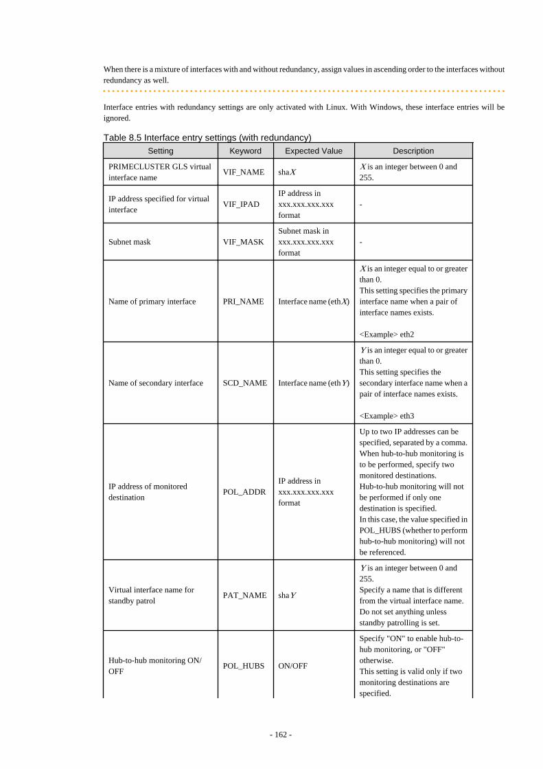
When there is a mixture of interfaces with and without redundancy, assign values in ascending order to the interfaces withoutredundancy as well.
Interface entries with redundancy settings are only activated with Linux. With Windows, these interface entries will beignored.
Table 8.5 Interface entry settings (with redundancy)
Setting Keyword Expected Value Description
PRIMECLUSTER GLS virtualinterface name
VIF_NAME shaXX is an integer between 0 and255.
IP address specified for virtualinterface
VIF_IPADIP address inxxx.xxx.xxx.xxxformat
-
Subnet mask VIF_MASKSubnet mask inxxx.xxx.xxx.xxxformat
-
Name of primary interface PRI_NAME Interface name (ethX)
X is an integer equal to or greaterthan 0.This setting specifies the primaryinterface name when a pair ofinterface names exists.
<Example> eth2
Name of secondary interface SCD_NAME Interface name (ethY)
Y is an integer equal to or greaterthan 0.This setting specifies thesecondary interface name when apair of interface names exists.
<Example> eth3
IP address of monitoreddestination
POL_ADDRIP address inxxx.xxx.xxx.xxxformat
Up to two IP addresses can bespecified, separated by a comma.When hub-to-hub monitoring isto be performed, specify twomonitored destinations.Hub-to-hub monitoring will notbe performed if only onedestination is specified.In this case, the value specified inPOL_HUBS (whether to performhub-to-hub monitoring) will notbe referenced.
Virtual interface name forstandby patrol
PAT_NAME shaY
Y is an integer between 0 and255.Specify a name that is differentfrom the virtual interface name.Do not set anything unlessstandby patrolling is set.
Hub-to-hub monitoring ON/OFF
POL_HUBS ON/OFF
Specify "ON" to enable hub-to-hub monitoring, or "OFF"otherwise.This setting is valid only if twomonitoring destinations arespecified.
- 162 -

Setting Keyword Expected Value Description
If only one monitoringdestination is specified, thissetting is disabled (set to "OFF").
Refer to the PRIMECLUSTER Global Link Services manual for details on each setting.
2. Enable the Network Parameter Auto-Configuration Function
Enable the network parameter auto-configuration function by executing the following command:Execute this command from a managed server.
[Windows]
>"Installation_folder\Agent\bin\rcxadm" lanctl enable <RETURN>
[Linux]
# /opt/FJSVrcxat/bin/rcxadm lanctl enable <RETURN>
For details on this command, refer to "5.6 rcxadm lanctl" of the "ServerView Resource Coordinator VE Command Reference".
8.6.1 Operation Checks and PreparationsUse the following procedure to actually apply the definition file's settings on the reference server and prepare a cloning image to be usedfor further server deployments. The definition file's settings applied from the definition file should be validated before image collectionby checking the reference server's behavior and configuration.
1. Manually Execute the Network Parameter Setup Command
Execute the network parameter configuration command on the reference server holding the prepared definition file and check thatthe defined settings are applied correctly.
Executing the Command
Before collecting the cloning image, run the following command to apply the definition file and verify that the defined settingsare actually reflected on the reference server. This command also activates network parameter auto-configuration for any cloningimage subsequently collected. Once this command has been executed, the network configuration that was described in thedefinition file will be perfumed automatically.
[Windows]
>"Installation_folder\Agent\bin\rcxadm" lanctl set <RETURN>
[Linux]
# /opt/FJSVrcxat/bin/rcxadm lanctl set<RETURN>
For details on this command, refer to "5.6 rcxadm lanctl" of the "ServerView Resource Coordinator VE Command Reference".
Validating Settings (Without LAN Redundancy)
Use a command provided by the operating system (ipconfig for Windows and ifconfig for Linux) to confirm that networkinterface settings (without redundancy) were correctly applied.
Validating Settings (With LAN Redundancy) [Linux]
Use the following commands to confirm that network interface settings (with redundancy) were correctly applied.
- Using the /opt/FJSVhanet/usr/sbin/dsphanet command
# /opt/FJSVhanet/usr/sbin/dsphanet <RETURN>
[IPv4,Patrol]
Name Status Mode CL Device
+----------+--------+----+----+------------------------------------------------+
- 163 -

sha0 Active e OFF eth0(ON),eth1(OFF)
sha2 Active p OFF sha0(ON)
sha1 Active e OFF eth2(ON),eth3(OFF)
[IPv6]
Name Status Mode CL Device
+----------+--------+----+----+------------------------------------------------+
Items to confirm
- The status of the virtual interface must be "Active".
- When the standby patrol function is used ("p" mode), the status of the virtual interface set in standby patrol ("sha2" in theoutput example above) must be "Active".
- Using the /opt/FJSVhanet/usr/sbin/dsppoll command
# /opt/FJSVhanet/usr/sbin/dsppoll <RETURN>
Polling Status = ON
interval(idle) = 5( 60)
times = 5
repair_time = 5
link detection = NO
FAILOVER Status = YES
Status Name Mode Primary Target/Secondary Target HUB-HUB
+------+------+----+-------------------------------------------+-------+
ON sha0 e 192.168.1.101(ON)/192.168.1.102(WAIT) ACTIVE
ON sha1 e 192.168.1.101(ON)/192.168.1.102(WAIT) ACTIVE
Items to confirm
- The monitoring status (Polling Status) must be "ON" (monitoring in progress).
- If one monitoring destination is specified, the status of that destination (Primary Target) must be "ON" (monitoring inprogress).
- If two monitoring destinations are specified, the status of the primary destination (Primary Target) must be "ON"(monitoring in progress) and the status of the secondary destination (Secondary Target) must be "WAIT" (on standby).
- When HUB-HUB monitoring is set to "ON", the status (HUB-HUB) must be "ACTIVE" (monitoring in progress).
If the interface settings have not been configured correctly, clear the settings using the rcxadm lanctl unset command, and thencorrect the definition file before executing the rcxadm lanctl set command again.If anything (including user-defined checks) does not turn out as expected even though the settings were applied correctly, checkthe network connections and the monitoring target, and take appropriate action.
Another test is to either deactivate the port on the LAN switch blade corresponding to the network interface wherecommunications are actually being performed, or disconnect the cable from an external port on the LAN switch blade, to checkwhether the spare network interface automatically takes over communication. If the standby patrol function is enabled, checkthe port status or check that the status of the standby network interface changes to "WAIT" after reconnecting the cable.
2. Collect a Cloning Image
Collect a cloning image from the managed server checked in step 1.
For details on how to collect a cloning image, refer to "8.2 Collecting a Cloning Image".
Note
[Linux]When a cloning image is collected, any LAN redundancy settings on managed servers are canceled, and only network parametersfor the defined public LAN are set up again when collection completes.If LAN redundancy has been manually set up, set the LAN redundancy settings again manually.
- 164 -

8.6.2 MaintenanceIf the network parameter auto-configuration function fails, an error message is output together with error details to the following file:
[Windows]Installation_folder\Agent\var\log\error_lan.log
[Linux]/var/opt/FJSVnrmp/logs/error_lan.log
For details on message meanings and appropriate corrective actions, refer to the "ServerView Resource Coordinator VE Messages".The file size limit is 32 KB and only one version is maintained. Old logs will have the extension ".old" appended to the file name andremain in the same directory.
8.6.3 Clearing SettingsThis section explains how to disable the network parameter auto-configuration function and clear the settings that were applied.
Disabling the Network Parameter Auto-Configuration Function
The network parameter auto-configuration function of the cloning image being collected can be disabled by executing the followingcommand.After disabling it, collect a new cloning image to update the existing image.
[Windows]
>"Installation_folder\Agent\bin\rcxadm" lanctl disable <RETURN>
[Linux]
# /opt/FJSVrcxat/bin/rcxadm lanctl disable <RETURN>
Clearing Network Parameter Settings
If network settings must be added or changed due to the addition of a new server, first clear the existing settings. Clear the networkparameter settings of managed server by executing the following command:
[Windows]
>"Installation_folder\Agent\bin\rcxadm" lanctl unset <RETURN>
[Linux]
# /opt/FJSVrcxat/bin/rcxadm lanctl unset <RETURN>
For details on this command, refer to "5.6 rcxadm lanctl" of the "ServerView Resource Coordinator VE Command Reference".
Note
[Windows/Linux]Network parameter settings for interfaces not designated in the definition file cannot be released.
[Linux]When this command is executed, any LAN redundancy settings for managed servers are unset. If LAN redundancy has been set up forthe admin LAN, set the LAN redundancy settings again manually.
8.6.4 Modifying the Operating EnvironmentUse the following procedures to modify the operating environment.
- 165 -

Deploying New Managed Servers with Automated Public LAN Configuration
Use the following procedure to add new managed servers and automate their public LAN settings using the network parameter auto-configuration function:
1. Register the newly added servers.
2. Perform the following procedure on a reference server chosen between already running servers:
a. Clearing Network Parameter Settings
Execute the rcxadm lanctl unset command to clear the network parameters configuration.
b. Editing the definition file
Set up a node entry in the definition file (ipaddr.conf) with the server name, interface entries, and other information for theserver to be added.
c. Manually execute network parameter settings
Execute the rcxadm lanctl set command to apply the network parameters and make sure that the resulted configuration (inducedfrom the definition file) is correct.
d. Collect the cloning image again.
3. Deploy the collected cloning image to the newly added servers.
Modifying Managed Server Settings
If network settings must be modified due to the addition or removal a public LAN, or a change of IP address; perform the following onan arbitrary reference server (chosen between already running servers).
1. Execute the rcxadm lanctl unset command to clear the network parameters configuration.
2. Edit the definition file to add, modify, or delete network parameters.
3. Execute the rcxadm lanctl set command to apply the network parameters and ensure that the resulted configuration (induced fromthe definition file) is correct.
4. Collect a new cloning image from the reference server.
- 166 -
Chapter 9 Server Switchover SettingsThis chapter explains how to use server switchover settings and automatically recover from server failures.
9.1 OverviewServer switchover is a feature that allows the user to switch over applications from a primary server to a predefined spare server when theprimary server fails or is stopped for maintenance.It can also perform Auto-Recovery, which automatically switches applications over to a spare server when a hardware failure is detectedon the primary server.Server switchover can be realized through four different methods, as described below. The switchover method used by a given server isautomatically selected when configuring its recovery settings. If HBA address rename settings were already made when applying recoverysettings, the HBA address rename method will be automatically selected. Similarly, the VIOM server profile exchange method isautomatically selected if a server profile was already assigned to the server in VIOM.However, each method has its own restrictions regarding the supported hardware environment. For details, refer to the corresponding"Note" in "1.2 Hardware Environment" of the "ServerView Resource Coordinator VE Installation Guide".
- Backup and restore method
In a local boot environment, this method restores a system image backup to a spare server, which is then automatically started up.This is selected under the following cases.
- When a virtual WWN or boot configuration have not been set via the HBA address rename or VIOM server profile assigned tothe primary server.
- Select the "Local-boot with SAN data (Backup and restore method)" checkbox when setting the spare server.
When HBA address rename or VIOM has been used to set a server profile for a server, the WWN and server profile also can beswitched at server switchover.After switchover, the operating system and its applications will resume on the spare server from the status they were in at the lastsystem image backup.Note that only the content of the first local disk (or boot disk) as seen by the BIOS of the managed server is subject to a backup orrestore operation, including all partitions (Windows drives or Linux partitions) present on the boot disk.However, since additional disks (disks used as data disks), are not subject to backup and restore, their content cannot be made accessibleto the spare server with a server switchover.When using more than one local disk, backup and restore of such additional data disks should be performed using external backupsoftware.However, when there are multiple sections on the first disk (Windows drives or Linux partitions), all sections become the target ofbackup and restore.
- HBA address rename method
In a SAN boot environment, this method sets the WWN of a spare server's HBA to the same value as that originally set on the primaryserver. This allows the spare server to connect to and boot from the same boot disk that was used by the primary server. This methodis used when HBA address rename settings have been made on the primary server. Because this method automatically starts the spareserver from the primary server's boot disk, applications can be resumed without users being aware of the hardware replacement thatoccurred.
- VIOM server profile exchange method
This method is used in SAN boot environments where servers start from boot disks located in storage arrays. If the primary serverfails, the WWN, MAC address, boot configuration, and network configuration set in its server profile are inherited by the spare server,which then automatically starts up from the same SAN disk. This method is used when a virtual WWN has been set via the VIOMserver profile assigned to the primary server. Because this method automatically starts the spare server from the primary server's bootdisk, applications can be resumed without users being aware of the hardware replacement that occurred.
- Storage affinity switchover method
When a primary server fails in a SAN boot environment, changing the following configuration using storage management softwareenables access and startup from the same boot disk. When HBA WWNs are fixed, reconfiguring storage devices enables continuationof operations.
- Zoning settings for the Fibre Channel switches connected to servers
- 167 -

- Host affinity settings for storage CAs
The HBA address rename and VIOM server profile exchange methods are also referred to as I/O virtualization methods.For PRIMERGY BX servers, the network configuration (VLAN IDs of adjacent LAN switch ports or port groups) of the primary serverwill be inherited by the spare server when using the backup and restore method, HBA address rename method, or the VIOM server profileexchange method.When using the VIOM server profile exchange or the backup and restore method, if a MAC address, boot configuration, or networkconfiguration were assigned to the server (in its VIOM server profile), these settings will also be inherited by the spare server. Therefore,it is no longer necessary to re-configure applications or network devices that depend on MAC address values.
After two servers have been switched over, a failback operation can switch them back to their original configuration using the sameswitchover method. Conversely, server takeover is the operation that appoints the activated spare server as the new primary server insteadof switching back servers to their original configuration.
Note
- The backup and restore, and HBA address rename methods are not available if ServerView Deployment Manager is used on the adminLAN. Refer to "Appendix J Co-Existence with ServerView Deployment Manager" for details.
- Auto-Recovery occurs when a hardware failure is detected. However, it does not occur when the operating system has stopped as aresult of a software error or when the operating system is automatically rebooted.Refer to "9.4 Conditions Required for Auto-Recovery" for details.Furthermore, since the Auto-Recovery is driven by a hardware failure, it prioritizes a fast recovery to a spare server instead of collectingan OS memory dump (which would be used to troubleshoot an OS failure).Thus, even if a memory dump was set to be collected in the event of an OS failure, server recovery will take precedence and thememory dump will not be collected.
- Server switchover can be realized using one of the following methods.
- Backup and restore method
- HBA address rename method
- VIOM server profile exchange method
- Storage affinity switchover method
- When configuring the HBA address rename function as the switchover method, first confirm that the HBA address rename settingshave been configured properly before configuring the server switchover settings.
- When server switchover is conducted using a Hyper-V VM host, prepare more than two physical NICs.The network which VM hosts, such as the admin LAN for VM hosts, use to communicate with external servers should be dedicatedonly to physical servers, and not be configured for virtual networks.In a network environment that has external virtual networks configured, disable all virtual networks for VM hosts. For details, referto "A.2 Configuration Requirements".
- It is not possible to specify spare servers for individual VM guests. It is either possible to store VM guests on a SAN or NAS shareddisk and assign a spare server to the VM host, or use the VM high-availability feature provided by the server virtualization softwareused.For details on the different high-availability features available in each server virtualization product, refer to "A.3 Functional Differencesbetween Products".Switchover using Resource Coordinator VE, and the high-availability of server virtualization software can be used together.When using a high-availability feature of server virtualization software, do not include spare servers of Resource Coordinator VE inVM hosts as spare servers.
[VMware]When using a high-availability feature (VMware HA) of server virtualization software, perform high-availability configuration againwhen performing server switchover or failback of Resource Coordinator VE.
- When primary and spare servers are placed in different chassis, and both servers are connected to LAN switch blades operating inIBP mode, server switchover only works if the following conditions are met.
- LAN switch blades are PRIMERGY BX900/BX400
- 168 -

- The same port group name is set for both LAN switch blades
- When using Intel PROSet for LAN redundancy, the switchover destination server may inherit the same MAC address as that of thesource server, as Intel PROSet keeps an internal definition of MAC addresses. When using Intel PROSet for LAN redundancy, theswitchover destination server may inherit the same MAC address as that of the source server, as Intel PROSet keeps an internaldefinition of MAC addresses. To avoid communication issues caused by MAC address conflicts, please be sure to re-configure MACaddresses on the destination server following a server switchover.
- For servers other than blade servers, configuration is not possible when there are managed servers belonging to different subnets fromthe admin server.
- Configuration is not possible when there are managed servers whose admin LAN NIC configurations are different from the primaryserver.
- Server switchover can be performed, even if the NIC configurations used for HBA address rename setup service on the primary serverand spare server are different. After server switchover is performed, the HBA address rename setup service may not operate dependingon the network configuration. Therefore, the NIC configurations used for the HBA address rename setup service should be the sameon both the primary server and the spare server.
In environments where there are servers running physical OS's and servers with VM hosts and VM guests, if they both use HBA addressrename or VIOM, by combining the following settings it is possible for a physical OS and a VM guest to share a spare server.For details, refer to "Figure 9.3 Sharing a Spare Server Between Physical OS's and VM Guests (High-availability Function of ServerVirtualization Software)" in "9.2 Configuration".
a. Specify a VM host as the spare server used to recover VM guests within the high-availability feature (VMware HA) of the servervirtualization software used.
b. Once the above settings have been made on a physical OS, a server failure will trigger the following recovery operations.
If the failed server was running a physical OS, Resource Coordinator VE will shut down the VM host on the spare server and switch thefailed physical OS over to the spare server. If the failed server was a VM host running VM guests, the high-availability feature providedwith the server virtualization software will recover the VM guests on the spare VM host server. Since physical OS's and VM guests sharea common spare server, the two types of recovery described above can perform together: once one type of recovery occurs on a spareserver, the other type of recovery can no longer be performed on that same spare server.
Information
- Server switchover based on backup and restore takes approximately 3 minutes, plus the time required to restore the system image.Image restoration time depends on different factors such as disk space and network usage, but as an estimate, a disk of 73GB will take30 to 40 minutes (the transfer of the system images takes between 10 to 20 minutes, while system restarts and other configurationchanges take another 20 minutes).
- Server switchover based on HBA address rename takes approximately 5 minutes, plus the time required to start up the original operatingsystem and services on the spare server. If a server OS was running on the spare server, the time required to shutdown the spare servermust also be included.
9.2 ConfigurationThis section provides examples of switchover configurations for each different switchover method.
Each method has its own restrictions regarding the supported hardware environment. For details, refer to the corresponding "Note" in "1.2Hardware Environment" of the "ServerView Resource Coordinator VE Installation Guide".
- Spare server configuration for local boot servers
A spare server should be set aside for servers in local boot environments.When a primary server fails, a system image (that must be backed up beforehand) will be restored to the spare server, and the spareserver will be started up. A spare server can be shared by multiple primary servers.
- 169 -

If a local boot server is using SAN storage for data storing purposes, I/O virtualization can make this SAN storage space accessibleto the spare server.
Figure 9.1 Spare Server Configuration for Local Boot Servers
- Spare server configuration for booting from SAN/iSCSI storage servers (using virtual I/O)
At least one spare server using virtual I/O should be set aside for servers in a SAN/iSCSI boot environment.When a primary server fails, the WWN set on its HBA or MAC address, boot configuration, and network configuration set on its NICis inherited by the spare server, which can then access and start up from the same boot disk. A spare server can be shared by multipleprimary servers.
Figure 9.2 Spare Server Configuration for Booting from SAN/iSCSI Storage Servers
For spare server configurations based on I/O virtualization, a spare server can be shared by multiple physical OS's and VM guests(using the high-availability feature provided with their server virtualization software). For details on the server virtualization softwaresupporting this configuration, refer to "A.1 Supported Functions".In this case, spare servers should be set up as a VM hosts booting from a SAN, so that when a physical server hosting VM guestsexperiences a failure, the high-availability feature provided with their server virtualization software can be used to transfer the VMguests to this spare VM host.
- 170 -

If a server running a physical OS fails, its boot disk will be reconnected to the spare server by means of an HBA address rename.When this happens, the spare server is halted, reconnected to the primary server's boot disk, and started up as the new active server.
Figure 9.3 Sharing a Spare Server Between Physical OS's and VM Guests (High-availability Function ofServer Virtualization Software)
In server configurations using I/O virtualization, servers on which a server OS is operating can be used for spare servers.If a primary server fails and its spare server boots from a SAN, the OS of the spare server will be stopped. After that the boot disk isconnected to the spare server using I/O virtualization, and the server started.
Figure 9.4 Configuration Using a Server on which a Server OS is Operating as a Spare Server
Note
A spare server cannot be shared by a local boot server, a SAN boot server, and an iSCSI boot server.
- Spare server configuration for booting from SAN storage servers (using storage management software)
Storage management software should be set aside for servers in SAN boot environments.When a primary server fails, changing the following configuration using storage management software enables access and startupfrom the same boot disk. A spare server can be shared by multiple primary servers.
- Zoning settings for the Fibre Channel switches connected to servers
- 171 -

- Host affinity settings for storage CAs
9.3 Server Switchover ConditionsThe following conditions must be satisfied for manual server switchover, failback, and Auto-Recovery to function correctly.
Conditions for Spare Servers
The spare server must be identical to the active server in the ways listed below.If these conditions are not satisfied, allocation of a spare server may not be possible, server switchover may fail, or the server maymalfunction after the switchover is completed.
- Server model
- Server hardware configuration
The following settings for optional cards and expansion boards must be the same.
- The locations they are mounted in
- The number and sizes of local disks
- RAID settings
There are no other hardware conditions for the spare server (such as memory capacity, number of CPUs and CPU clock speed).However, the hardware configuration of the spare server must be capable of running the operating system and applications runningon the primary server.
- BIOS settings
The same BIOS settings must have been made for all servers according to the procedure in "BIOS Settings for Managed Servers" in"3.5 Configuring the Server Environment".
- OBP settings
For SPARC Enterprise, the OBP settings to start automatically from SAN servers of the same target disk must have been madeaccording to the procedure in "OBP (Open Boot Prom) Settings (SPARC Enterprise)" in "3.5 Configuring the Server Environment".With the storage affinity switchover method, as setting changes are only performed for Fibre Channel switch storage devices, it isnecessary to perform configuration of servers that will be changed during switchover, and HBA and OBP settings.
- LAN and SAN access scope
The spare server must use the same network redundancy method, have the same redundancy paths, and have access to the same networkand storage devices. Note that LAN or fibre channel switches connected in a cascade configuration are viewed as a single device.
- Firewall
There must be no firewall between the primary server and the spare server.
- Subnet
For servers other than blade servers, the primary server and the spare server must belong to the same subnet.
If a spare server is shared by a physical OS and one or more VM guests (using the high-availability feature provided with their servervirtualization software), the spare server must be configured for SAN boot using I/O virtualization.
For details, refer to "Figure 9.3 Sharing a Spare Server Between Physical OS's and VM Guests (High-availability Function of ServerVirtualization Software)" in "9.2 Configuration".
When using a server on which a server OS is operating as a spare server, both the primary server and spare server should be in a configurationthat uses I/O virtualization.For details, refer to "Figure 9.4 Configuration Using a Server on which a Server OS is Operating as a Spare Server" in "9.2 Configuration".
Also, if more than two local disks are connected to a spare server in a backup/restore configuration, and if the partitioning of the diskscoming after the first in the boot order is different than the first disk, a warning message may be displayed at restart, or the operatingsystem may not restart, causing any switchovers initiated to fail. After configuring the spare server, verify that it is operating properly byperforming a switchover and failback.
- 172 -

If the operation fails, configure the partitions other than the first boot disk of the spare server to match the configuration of the primaryserver, or set up the primary server configuration so that it does not depend on any disk other than the first, using automatic service startupsand re-labeling the Windows drives as necessary.
With blade servers, if the primary server and spare server do not belong to the same subnet, if server switchover is performed to the spareserver it is necessary that the VLAN ID or port group settings of the internal LAN switch ports are adjusted automatically.For the setting method, refer to "9.6 Server Switchover Settings".
Conditions for Server Switchover
The following conditions must be satisfied for a server switchover or Auto-Recovery to succeed:
- The server configuration cannot already be switched over (the primary server must be the active server).
- The status of the spare server must be "normal", "warning" or "stop". If a VM host has been installed on the spare server(for VMwareHA), its status must be either "normal" or "warning".
- If a spare server is shared by more than one active server, none of the other primary servers may be switched over to that spare server.
- If the server is in a local boot environment, its system image must have been backed up.
Conditions for Server Failback
The following conditions must be satisfied for server failback to succeed:
- The active server must have been switched over to the spare server.
- The status of the primary server must be "stop".
- If the server is in a local boot environment, its system image must have been backed up.
9.4 Conditions Required for Auto-RecoveryThis section explains the conditions required for auto-recovery.
Auto-Recovery Using Server Switchover Settings
A server for which Auto-Recovery is enabled will be automatically switched over to its spare server if Resource Coordinator VE detectsboth a failure from the server hardware and determines that its physical OS (or VM host) has stopped.
- Detecting hardware failures from servers
A hardware failure can be detected by an "Error" level SNMP trap failure notification sent to the admin server from either theServerView Agent or the server management unit. Alternatively, Resource Coordinator VE can detect a failure by periodically pollingthe status of each managed server.
Detectable hardware failures
- CPU faults
- Memory errors
- Temperature abnormalities
- Fan failures
As a result of a FAN failure, it is detected as a temperature abnormality.
- Detecting that a physical OS (or VM host) has stopped
A physical OS (or VM host) is seen to have stopped abnormally when the following conditions are met:
- PRIMERGY BX series servers
An abnormal server status is obtained from a server management unit, and it is not possible to communicate with either theServerView Agent or the Resource Coordinator VE agent
- 173 -

- For rack mount, tower, and SPARC Enterprise servers
Communication using the ping command is unavailable
Auto-Recovery Using Monitoring Information Settings
When ping monitoring using monitoring information is enabled, server switchover is automatically performed when there is no responsefrom physical OS on servers or VM hosts, and restoration by executing reboot fails.The recovery process can be changed by configuring settings. For details on how to configure these settings, refer to "6.2.6 ConfiguringMonitoring Information".
- No response detected by ping monitoring
When the period with no response in the ping command is over the time-out value, no response is detected.
Note
- Notification of hardware failures on rack mount servers, tower servers, and SPARC Enterprise servers is only detected by SNMPtraps.
- Auto-Recovery is not triggered on servers that are in maintenance mode.
- Even if a hardware failure is detected, Auto-Recovery will not be triggered if no response is received from the target server. In suchcases, shutting down or restarting the server will temporarily stop the operating system, triggering an automatic switchover as theconditions for Auto-Recovery will be met. Under such conditions, automatic switchovers can be prevented by setting the server tomaintenance mode before shutdown or restart.
9.5 Status DisplayCurrent recovery settings can be confirmed by selecting a physical OS or VM host in the server resource tree of the RC console and fromthe spare server settings displayed in the [Resource Details] tab.
The following information is displayed:
Primary server
Displays the name of the physical server that will be replaced when server switchover occurs.
Active server
Displays the name of the physical server that is currently running.
Server switchover method
Displays the specified server switchover method.
Automatic server recovery
Shows whether automatic server recovery is enabled or not.
Network switchover
Shows whether network settings will be automatically adjusted during server switchover.
Spare server
Displays the name of the physical server that will replace the current active server when server switchover occurs.More than one spare server will be displayed if more than one has been specified.
9.6 Server Switchover SettingsUse the following procedure to configure server switchover settings:
When using local disks as system disks, and iSCSI storage as data disks, refer to the advisory notes described in "Table 3.1 SupportedStorage Device Configurations" of "3.3.1 Storage Configuration".
- 174 -

1. In the RC console server resource tree, right-click a server (or a physical OS or VM host on the server) and select [Modify]-[SpareServer Settings] from the pop up menu.
The [Spare Server Settings] dialog is displayed.
2. In the [Spare Server Settings] dialog, set the following parameters:
Spare server
From the spare server list, select the checkbox in the "Select" column of the server that is to be used as the spare server.One or more spare servers can be specified, including spare servers from different chassis.
If more than one is specified, an unused spare server will be selected from the list of available candidates when a server switchoveroccurs.
Information
With the storage affinity switchover method, a server for which WWN settings have been performed can only be used as a spareserver for a primary server with WWN settings. When using the storage affinity switchover method, it is necessary to configurethe target CA so that it matches the WWPN value in the access path settings of the actual server. Hyphens ("-") must be specifiedfor target CAs of spare servers using the storage affinity switchover method.
Applying the patch T005054WP-05 [Windows] and T005069LP-05 [Linux] for the manager, enables a server on which an agentis registered to be used as a spare server. When using a server on which an agent is registered as a spare server, the server mustmeet one of the following conditions: ETERNUS SF Storage Cruiser cannot perform event monitoring of spare servers. Fordetails on event monitoring, refer to the "ETERNUS SF Storage Cruiser Event Guide".
- When the WWPN of the target CA is the same value as that of the primary server
- When the AffinityGroup value is different from the value of the primary server
- When agents are not registered on ETERNUS SF Storage Cruiser
In server configurations using I/O virtualization, servers on which server OS's are operating can be used for spare servers.
- Register the agent
- I/O virtualization
- Server switchover settings
To change a server with the above settings, which does not use I/O virtualization, to a spare server, delete the server and thenre-register it. Note that if the server is registered while it is running, an agent will be registered automatically. For this reason itshould be registered while it is stopped. For details on server registration, refer to "6.1.3 Registering Managed Servers".
To delete a spare server that has been added, refer to "9.8 Cancelling Server Switchover Settings".
"Local-boot with SAN data (Backup and restore method)" checkbox
This checkbox is available only if the WWN of the servers selected from the server resource tree are being virtualized usingHBA address rename or VIOM.The checkbox is unavailable if the WWN is not being virtualized or boot configuration is set for a VIOM server profile.Select this option for servers that boot from a local disk while using SAN storage to store data. If selected, spare server(s) willalso be able to boot locally and access the same SAN storage data space after a switchover.Do not select this option for servers that boot from a SAN disk.
"Apply network settings when the server is switched over" checkbox
Select this option to enable automatic adjustment of VLAN ID or port group settings during a server switchover. If selected, theinternal LAN switch ports connected to the spare server will be set with the same VLAN settings as those of the ports connectedto the primary server.This option is selected by default.This feature is available only for PRIMERGY BX blade servers.When VIOM is used, it is available only when a LAN switch is in switch mode.
- 175 -

Note
Do not select this option if VLAN settings are to be manually adjusted from the LAN switch's management interface (eithergraphical or command-line interface).
"Automatically switch over when a server fault is detected" checkbox
Select this option to enable Auto-Recovery.Server failures are detected when the server's status changes to "error" or "fatal" and its operating system stops functioning.Do not select this option if primary servers are to be manually switched over.This option is selected by default.
"Power off forced when the server is switched over" checkbox
Check this checkbox if the spare server is to be turned off forcibly when the spare server in started before switchover takes place.When shutting down the spare server, clear this checkbox.This option is not selected by default.
"Switchover to server where VM guest exists" checkbox
When a spare server is a VM host, check this checkbox if switching to a spare server in which the VM host contains a VM guest.When not switching to a VM host which contains a VM guest, clear this checkbox.This option is not selected by default.
3. Click <OK>.
The server switchover settings are configured.
Point
The conditions specified in "9.3 Server Switchover Conditions" must be satisfied for a server switchover to execute correctly.Once settings are complete, perform switchover and failback on each spare server that has been set up to verify that these operations canbe executed correctly.For details on switchover and failback methods, refer to "Chapter 10 Server Switchover" in the "ServerView Resource Coordinator VEOperation Guide".
Note
For servers other than those using I/O virtualization and those with WWN settings registered, the following checks will not be enabled.For servers with WWN settings registered, applying the patch T005054WP-05 [Windows] and T005069LP-05 [Linux] for the manager,enables the following checks:
- "Power off forced when the server is switched over" checkbox
- "Switchover to server where VM guest exists" checkbox
[VM host]The automatic startup of VM guests after the switchover of their VM host depends on their virtual machines' startup configuration withinthe server virtualization software used.Refer to the manual of each server virtualization product for details.According to the server virtualization product used, a newly created VM guest may require some re-configuration before running a serverswitchover.Refer to "A.2 Configuration Requirements" for details on such settings.
9.7 Changing Server Switchover SettingsThe procedure used to change server switchover settings is the same as that described in "9.6 Server Switchover Settings".For details, refer to "9.6 Server Switchover Settings".
- 176 -

9.8 Cancelling Server Switchover SettingsUse the following procedure to cancel server switchover settings.
1. In the RC console server resource tree, right-click a server (or a physical OS or VM host on the server) and select [Modify]-[SpareServer Settings] from the popup menu.
The [Spare Server Settings] dialog is displayed.
2. In the [Spare Server Settings] dialog, clear the checkbox in the "Select" column for the desired spare server.
3. Click <OK>.
The selected spare server is no longer set as a spare server.
- 177 -

Chapter 10 Saving Environment SettingsThis chapter explains how to save environment settings.
The configuration of a Resource Coordinator VE setup can be saved to guard against unexpected problems. Use the pre-configurationexport function and the troubleshooting data collection command (rcxadm mgrctl snap) to save settings.This troubleshooting data can be used in conjunction with the data later collected when a problem occurs for a more effective investigation,and should therefore be stored with caution.
See
- Refer to "7.3 Exporting the System Configuration File" for details on the pre-configuration function.
- For details on the collection of troubleshooting data, refer to "15.1 Types of Troubleshooting Data" in the "ServerView ResourceCoordinator VE Operation Guide".
- For details on these commands, refer to "5.7 rcxadm mgrctl" of the "ServerView Resource Coordinator VE Command Reference".
- 178 -
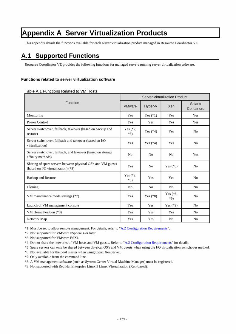
Appendix A Server Virtualization ProductsThis appendix details the functions available for each server virtualization product managed in Resource Coordinator VE.
A.1 Supported FunctionsResource Coordinator VE provides the following functions for managed servers running server virtualization software.
Functions related to server virtualization software
Table A.1 Functions Related to VM Hosts
Function
Server Virtualization Product
VMware Hyper-V XenSolaris
Containers
Monitoring Yes Yes (*1) Yes Yes
Power Control Yes Yes Yes Yes
Server switchover, failback, takeover (based on backup andrestore)
Yes (*2,*3)
Yes (*4) Yes No
Server switchover, failback and takeover (based on I/Ovirtualization)
Yes Yes (*4) Yes No
Server switchover, failback, and takeover (based on storageaffinity methods)
No No No Yes
Sharing of spare servers between physical OS's and VM guests(based on I/O virtualization) (*5)
Yes No Yes (*6) No
Backup and RestoreYes (*2,
*3)Yes Yes No
Cloning No No No No
VM maintenance mode settings (*7) Yes Yes (*8)Yes (*6,
*9)No
Launch of VM management console Yes Yes Yes (*9) No
VM Home Position (*8) Yes Yes Yes No
Network Map Yes Yes No No
*1: Must be set to allow remote management. For details, refer to "A.2 Configuration Requirements".*2: Not supported for VMware vSphere 4 or later.*3: Not supported for VMware ESXi.*4: Do not share the networks of VM hosts and VM guests. Refer to "A.2 Configuration Requirements" for details.*5: Spare servers can only be shared between physical OS's and VM guests when using the I/O virtualization switchover method.*6: Not available for the pool master when using Citrix XenServer.*7: Only available from the command-line.*8: A VM management software (such as System Center Virtual Machine Manager) must be registered.*9: Not supported with Red Hat Enterprise Linux 5 Linux Virtualization (Xen-based).
- 179 -

Table A.2 Functions Related to VM Guests
Function
Server Virtualization Product
VMware Hyper-V XenSolaris
Containers
Monitoring (*1) Yes (*2) YesYes (*2,
*5)Yes
Power control (*2) Yes Yes Yes (*3) Yes
Migration between physical servers Yes (*4) Yes (*4) Yes No
Launch of VM management console Yes Yes Yes (*6) No
*1: VM guests are automatically detected after VM host registration. The result of further VM guest creation, modification, removal, ormigration is also automatically reflected in Resource Coordinator VE.*2: Depending on the virtualization software used, this function may require specific settings. Refer to "A.2 ConfigurationRequirements" for details.*3: An error may happen when using the high-availability function of a server virtualization software. For details, refer to "A.3 FunctionalDifferences between Products".*4: A VM management software (such as VMware vCenter Server, System Center Virtual Machine Manager) must be registered.*5: Not supported with Red Hat Enterprise Linux 5 Linux Virtualization (Xen-based). To register VM guests, they should be powered onfirst.*6: Not supported with Red Hat Enterprise Linux 5 Linux Virtualization (Xen-based).
Attributes of VM Hosts and VM Guests
Table A.3 General Area
Content displayed
Server Virtualization Product
VMware Hyper-V XenSolaris
Containers
Server name Yes Yes Yes Yes
Admin LAN (IP address) (*1) Yes Yes Yes Yes
Status Yes Yes Yes Yes
Type Yes Yes Yes Yes
OS Yes Yes Yes (*2) Yes
Physical server name (*1) Yes Yes Yes Yes
*1: Not displayed for VM guests.*2: Not supported with Red Hat Enterprise Linux 5 Linux Virtualization (Xen-based).
Table A.4 VM Host Information Area
Content displayed
Server Virtualization Product
VMware Hyper-V XenSolaris
Containers
VM type Yes Yes Yes Yes
VM software name Yes Yes Yes Yes
VM software VL Yes Yes Yes Yes
Number of VM guests Yes Yes Yes Yes
VM management software Yes No No No
VM guests Yes Yes Yes Yes
- 180 -

Table A.5 VM Guest Information Area
Content displayed
Server Virtualization Product
VMware Hyper-V XenSolaris
Containers
VM type Yes Yes Yes Yes
VM host name Yes Yes No Yes
VM name Yes Yes Yes Yes
VM management software Yes No No No
A.2 Configuration RequirementsThis section describes the settings required to properly configure each different virtualization product for use with Resource CoordinatorVE.
Configuration Requirements for Each Server Virtualization Product
The required configuration differs with each server virtualization product. For details on the configuration of each virtualization product,refer to the manual of each product.
[VMware]Installation of VMware Tools is required to properly display the hostnames of guest OS's and enable their remote shutdown via the powercontrol functions of Resource Coordinator VE.Install VMware Tools after installing an operating system in a VM guest.
[Hyper-V]
- Use the following procedure to enable remote management.
1. Enable remote control in WMI settings.
a. In each VM host, access the Control Panel and open the [Administrative Tools]-[Computer Management].The [Computer Management] dialog is displayed.From the [Computer Management] dialog, open [Services and Applications], right-click on [WMI Control] and select[Properties] from the displayed menu.The [WMI Control Properties] dialog is displayed.
b. In the [WMI Control Properties] dialog, open the [Security] tab, select [Root]-[virtualization] and click <Security>.The [Security for ROOT\virtualization] dialog is displayed.
c. In the [Security for ROOT\virtualization] dialog, select the VM host's user name, select the "Allow" checkbox for "RemoteEnable" and click <OK>.
The remote enable of WMI is set.
2. Configure the Windows firewall to enable remote WMI management.
a. In each VM host, run the "GPedit.msc" command.The [Local Group Policy Editor] dialog is displayed.
b. In the [Local Group Policy Editor] dialog, open the following folder.[Computer Configuration]-[Administrative Templates]-[Network]-[Network Connections]-[Windows Firewall]
c. If the VM host is a member of a domain, double-click [Domain Profile]; otherwise double-click [Standard Profile].Either one of the [Domain Profile] or [Standard Profile] screen is displayed.
d. In the displayed screen, right-click "Windows Firewall: Allow inbound remote administration exception" and select[Properties] from the displayed menu.The [Windows Firewall: Allow inbound remote administration exception] dialog is displayed.
e. Select "Enabled" and click <OK>.
- 181 -

3. Configure DCOM.
a. In each VM host, run the "Dcomcnfg.exe" command.
b. In the [Component Services] dialog, expand [Component Services]-[Computers], right-click [My Computer] and select[Properties] from the displayed menu.The [My Computer Properties] dialog is displayed.
c. In the [My Computer Properties] dialog, open the [COM Security] tab.
d. Click <Edit Limits> under "Launch and Activation Permissions".The [Launch and Activation Permission] dialog is displayed.
e. In the [Launch and Activation Permission] dialog, select the VM host's user name under "Groups or user names:", andselect the "Allow" checkbox for "Remote Activation" and click <OK>.
f. Click <Edit Limits> under "Access Permissions".The [Access Permission] dialog is displayed.
g. In the [Access Permission] dialog, select "ANONYMOUS LOGON" under "Groups or user names:", select the "Allow"checkbox for "Remote Access" and click <OK>.
- Perform configuration so that the networks of VM hosts and VM guests are not shared.
1. Prepare more that two physical NICs.The physical NIC that the VM host uses for the admin LAN and communication with external servers should only be used forphysical servers. Please do not configure it for virtual networks.
2. Create a virtual network for the VM host to use for communication.
- For Hyper-V 2.0
Open the Hyper-V Manager, then [Virtual Network Manager] to create the virtual network. Clear the "Allow managementoperating system to share this network adapter" checkbox. (By default, the checkbox is unselected)
- For Hyper-V 1.0
On each VM host, access the Control Panel and open the [Network Connections]. Disable all external virtual networkconnections for the VM host which are displayed as "Local Area Connection".
- Installation of VMware Tools is required to properly display the host names of guest OS's and enable their remote shutdown via thepower control functions of Resource Coordinator VE.
Install OS's on VM guests and then install the integration service on those OS's.
[Xen]With Citrix XenServer, perform settings to enable remote shutdown of VM guests via the power control functions of Resource CoordinatorVE.Install XenServer Tools after installing an operating system in a VM guest.
[Solaris Containers]Set SSH access permission for accounts with administrator privileges, and enable password authentication.
Note
[Hyper-V]If a VM host belongs to a domain, make sure that its host name can be properly resolved by the admin server (from the VM host IP address).If host name resolution fails, perform the necessary DNS (or hosts file) settings to enable host name resolution.
[Xen]
- Make sure that each VM host is able to resolve the host name of the admin server from its IP address (on the admin LAN).If host name resolution fails, perform the necessary DNS (or hosts file) settings to enable host name resolution.
- When using Citrix XenServer with a resource pool, confirm that a home server is set for each VM guest.If no Home server is set, Resource Coordinator VE is only able to recognize active VM guests. For details, refer to "A.3 FunctionalDifferences between Products".
- 182 -

- When using Citrix Essentials for XenServer with a resource pool, high-availability should be enabled for that resource pool.If high-availability is not enabled, and the pool master become unreachable, Resource Coordinator VE will not be able to control orget information from the VM hosts and VM guests placed in that resource pool. If VM guest statuses become out-of-date, or operationson VM hosts or VM guests fail, check the status of the pool master. If the pool master is not reachable, resolve any communicationproblem that may prevent the manager from communicating with it (if necessary, change the pool master to another VM host).For details, refer to the server virtualization software manual.
Configuration Requirements for System Center Virtual Machine Manager
The following settings are required when registering and using System Center Virtual Machine Manager (hereafter SCVMM) as VMmanagement software.
1. Install Windows PowerShell.
Install PowerShell 2.0 or later on the admin server if it was not installed yet.
2. Configure Windows Remote Management settings.
- VM management software
Remote administration rights should be granted on the server where SCVMM is installed.
a. Log in to the SCVMM server as the administrator.
b. Run the following command from the command prompt.
>winrm quickconfig <RETURN>
c. Reply "y" to the confirmation that follows execution of the above command.
- Admin server
Configure Windows Remote Management authentication settings on the admin server.
a. Log on to the admin server as the administrator.
b. Run the following command from the command prompt.
>winrm set winrm/config/client @{TrustedHosts="SCVMM_server_ip_address"} <RETURN>
3. Configure the settings to enable communication with the admin LAN addresses of managed VM hosts.
From the server on which VM management software is operating, configure the settings to enable communication with the adminLAN IP addresses of the managed VM hosts to register in Resource Coordinator VE. Even if a multi-homed VM host has multipleIP addresses, it is necessary to enable communication from SCVMM with the interface connected to the admin LAN of the VMhost.
Configuration Requirements for VM Guest Switchovers
Depending on the virtualization product being used, the following settings should be made to enable switchover of a newly created VMguest.
[VMware]The VM guest's UUID must be changed.Perform the following settings before switchover of a VM guest.
From the VM management client, add the following parameter to the VM guest's virtual machine configuration.
Name Value
uuid.action keep
For details on how to add parameters to a virtual machine configuration, refer to the help section of the VM management client.
- 183 -

Without this setting, a confirmation dialog is shown each time a virtual machine is started after being moved to a different VM host.Enabling this setting will prevent such confirmation dialogs from being shown, and the virtual machine will be set to always keep its UUIDwhen moved between different servers.
[Hyper-V]No specific configuration is required.
[Xen]No specific configuration is required.
Starting VM Management Software Clients
[VMware]VMware Infrastructure Client or VMware vSphere Client should be installed on the Resource Coordinator VE admin client.
[Hyper-V]Hyper-V Manager or a VMM Administrator Console (*1) should be installed on the Resource Coordinator VE admin client.
*1:When System Center Virtual Machine Manager (SCVMM) is registered, this VMM Administrator Console is used to control the VMhosts managed by SCVMM.
[Xen]When using Citrix XenServer, XenCenter should be installed on the Resource Coordinator VE admin client.
Configuring for Receiving SNMP Traps from VM Management Software (VMware vCenter Server)
Configure the following settings when receiving SNMP traps from VM management software (VMware vCenter Server).
- SNMP trap destination configuration
Configure the IP address of the admin server as the SNMP trap destination on VM management software (VMware vCenter Server).For details on the configuration method, refer to the VM management software (VMware vCenter Server) manual.
- VM management software (VMware vCenter Server) alarm creation
Create an alarm for VM management software (VMware vCenter Server), and configure the conditions to send SNMP traps.For details on the configuration method, refer to the VM management software (VMware vCenter Server) manual.
- VM management software (VMware vCenter Server) registration
Register VM management software (VMware vCenter Server) on the admin server. At this point, register the SNMP trap source IPaddress of the VM management software (VMware vCenter Server).
The SNMP trap source IP address can be checked and changed using the following procedure.
1. Log in to the VM management software (VMware vCenter Server) server.
2. Access the Control Panel and open the "Network Connections".The [Network Connections] window is displayed.
3. From the menu, select [Advanced]-[Advanced Settings].The [Advanced Settings] window is displayed. The IP address in "Connections" on the [Adapters and Bindings] tab that hasthe highest priority and is allocated to an enabled network interface is the current SNMP trap source IP address.
4. To change the SNMP trap source IP address, select the network interface with the IP address you want to change from"Connections", and move it to the top of the list.
5. Click <OK>.
6. Restart the server if necessary.
- 184 -
Note
- The traps received from VM management software (VMware vCenter Server) are always displayed as warning level for ResourceCoordinator VE. Therefore, configure an alarm for VM management software (VMware vCenter Server) in order to send SNMP trapswhen an event with a level higher than warning occurs.
- When the language of the VM management software (VMware vCenter Server) and the manager are different, received SNMP trapmessages may turn into garbled characters.
A.3 Functional Differences between ProductsThis section describes the functional differences of each server virtualization product when used with Resource Coordinator VE.
Display of VM Guest Names
The names of VM guests displayed in Resource Coordinator VE vary according to the server virtualization product used.
[VMware]The RC console displays either a VM guest's VM name (as defined within VMware), or the hostname of its guest OS.The guest OS hostname is displayed only after VMware Tools have been installed and the VM guest has been restarted once. The followingconditions illustrate this behavior.
- VMware Tools were not installed yet: the VM name is displayed
- VMware Tools were installed, but the VM guest was not restarted yet: the VM name is displayed
- VMware Tools were installed, and the VM guest restarted: the hostname of the guest OS is displayed
If symbols were used in the VM name, those may be shown as percent signs ("%") or a pair of hexadecimal characters (example: "%5c").Such behavior is similar to that of some parts of VMware's management console.
[Hyper-V]The RC console displays either a VM guest's VM name (as defined within Hyper-V), or the hostname of its guest OS.The guest OS hostname is displayed after the VM guest has been started up at least once.
[Xen]The RC console displays the Xen VM names obtained at the time of VM host registration.Once a VM guest is registered, VM name changes made from the Xen administration client will not be reflected in the RC console.
[Solaris Containers]The VM guest names displayed on the RC console are the Solaris zone names set when creating Solaris containers.
Power Control of VM Guests [Xen]
- When using Citrix XenServer in a high-availability configuration, VM guests cannot be shut down if the automatic reboot option (forVM guests) is enabled.For details, refer to the server virtualization software manual.
- When using Red Hat Enterprise Linux 5 Virtualization (Xen-based), Resource Coordinator VE cannot perform power operations onsuspended VM guests. Suspended VM guests should first be resumed directly from the VM host console.
VM Guest Statuses [Solaris Containers]
The Solaris zone from before installation of the OS on a Solaris container is not displayed as the VM guest.
- 185 -
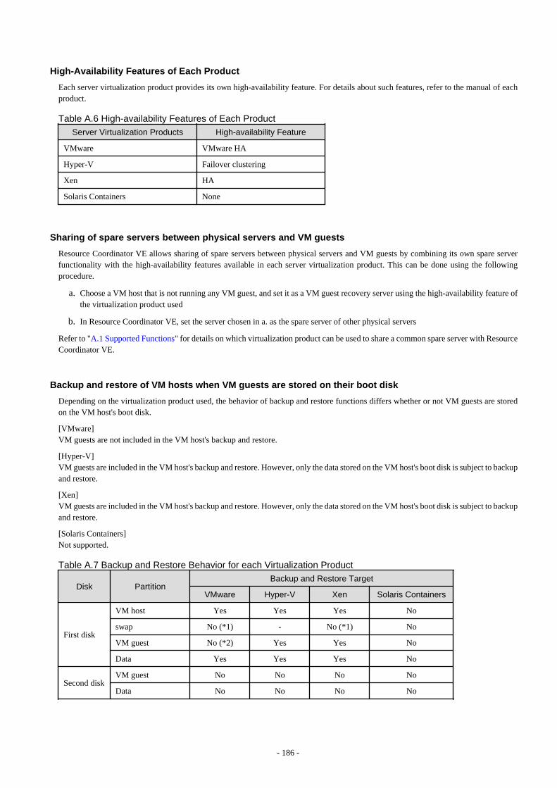
High-Availability Features of Each Product
Each server virtualization product provides its own high-availability feature. For details about such features, refer to the manual of eachproduct.
Table A.6 High-availability Features of Each Product
Server Virtualization Products High-availability Feature
VMware VMware HA
Hyper-V Failover clustering
Xen HA
Solaris Containers None
Sharing of spare servers between physical servers and VM guests
Resource Coordinator VE allows sharing of spare servers between physical servers and VM guests by combining its own spare serverfunctionality with the high-availability features available in each server virtualization product. This can be done using the followingprocedure.
a. Choose a VM host that is not running any VM guest, and set it as a VM guest recovery server using the high-availability feature ofthe virtualization product used
b. In Resource Coordinator VE, set the server chosen in a. as the spare server of other physical servers
Refer to "A.1 Supported Functions" for details on which virtualization product can be used to share a common spare server with ResourceCoordinator VE.
Backup and restore of VM hosts when VM guests are stored on their boot disk
Depending on the virtualization product used, the behavior of backup and restore functions differs whether or not VM guests are storedon the VM host's boot disk.
[VMware]VM guests are not included in the VM host's backup and restore.
[Hyper-V]VM guests are included in the VM host's backup and restore. However, only the data stored on the VM host's boot disk is subject to backupand restore.
[Xen]VM guests are included in the VM host's backup and restore. However, only the data stored on the VM host's boot disk is subject to backupand restore.
[Solaris Containers]Not supported.
Table A.7 Backup and Restore Behavior for each Virtualization Product
Disk PartitionBackup and Restore Target
VMware Hyper-V Xen Solaris Containers
First disk
VM host Yes Yes Yes No
swap No (*1) - No (*1) No
VM guest No (*2) Yes Yes No
Data Yes Yes Yes No
Second diskVM guest No No No No
Data No No No No
- 186 -

*1: During backup, data cannot be collected from the swap area. During restoration, the partition settings of the swap area are restored.*2: VMFS partitions are not subject to backup and restore.
VM Guest Migration
For VMware or Hyper-V environments, VMware vCenter Server or System Center Virtual Machine Manager should be registered as VMmanagement software to enable VM guest migrations.Depending on the server virtualization software used, the following remarks apply. For details, refer to the server virtualization softwaremanual.
[VMware]The source and destination VM hosts should be registered as part of the same cluster on the VM management software.For details on clusters on VM management software, refer to the server virtualization software manual.
[Hyper-V]The source and destination VM hosts should be part of the same Windows 2008 failover cluster.For details on failover clusters, refer to the Windows operating system manual.
[Xen]With Citrix XenServer, a migrated VM guest may be temporarily suspended before migration. Refer to the Citrix XenServer manual fordetails on the migration process and the conditions behind this behavior.
[Solaris Containers]Not supported.
The terminology used to describe different types of VM guest migration may differ depending on each virtualization vendor. For unificationpurposes, Resource Coordinator VE uses the following terminology.
Table A.8 Migration Terminology
Resource Coordinator VEterminology
VMware Terminology Meaning
Live migration VMotionMigration of an activevirtual machine(without interruption)
Cold migration Cold migrationMigration of a poweredoff virtual machine
VM Guest Statuses
Displayed VM guest statuses may differ depending on the configuration of its server virtualization environment.
[VMware]
- If no VM management software was registered in Resource Coordinator VE
VM guest statuses can be one of the following: "normal", "unknown", or "stop".
- If a VM management software was registered in Resource Coordinator VE
VM guest statuses can be one of the following: "normal", "warning", "error", "unknown", or "stop".
[Hyper-V]
- If no VM management software was registered in Resource Coordinator VE
VM guest statuses can be one of the following: "normal", "unknown", or "stop".
- If a VM management software was registered in Resource Coordinator VE
VM guest statuses can be one of the following: "normal", "stop", "unknown", or "error".
- 187 -

[Xen]VM guest statuses can be one of the following: "normal", "unknown", "stop", or "error".
[Solaris Containers]VM guest statuses can be one of the following: "normal", "unknown", or "stop".
VM Maintenance Mode
The terminology used to describe VM maintenance mode may differ depending on each virtualization vendor. For details on VMmaintenance mode settings and their requirements, refer to the manual of each product.
Table A.9 VM Maintenance Mode Terminology
Server Virtualization Products Vendor Terminology
VMware Maintenance mode
Hyper-V Maintenance mode (*1)
Xen Maintenance mode (*2)
Solaris containers None
*1: Only available with System Center Virtual Machine Manager (SCVMM). Maintenance mode for Hyper-V is made available inResource Coordinator VE by integrating directly with SCVMM.*2: Only available with Citrix XenServer. Red Hat Enterprise Linux 5 Virtualization (Xen-based) does not provide similar functionality.Moreover, the following restrictions may apply depending on the server virtualization product used.
[VMware]None.
[Hyper-V]Target VM hosts should be registered in SCVMM and SCVMM in turn properly registered in Resource Coordinator VE.
[Xen]With Citrix XenServer, a VM host assigned as a pool master cannot be put into maintenance mode.To put such a VM host into maintenance mode, the pool master role should first be assigned to a different VM host (within the sameresource pool).
Migration Conflicts
A VM guest migration may fail if another migration was already launched from outside (*1) or Resource Coordinator VE. In such cases,select [Operation]-[Update] from the RC console menu to refresh the screen and check that the VM guest is not already being migrated.
[Xen]With Citrix XenServer, "Home server" should be set for VM guests running on the VM hosts registered in the resource pool. Otherwise,powered off VM guests will no longer be recognized by Resource Coordinator VE. If a VM guest is no longer displayed in the RC consoleafter a screen update, confirm that "Home server" is set.
*1: This may happen when using an automatic migration feature within the server virtualization software, or when a migration was rundirectly from a VM management console. Refer to the virtualization software manual for details on automatic migration features.
Notes on Resource Pool Usage [Xen]
When using Citrix XenServer with a resource pool, if the pool master becomes inaccessible from the Resource Coordinator VE managerthe statuses of VM hosts and VM guests belonging to that resource pool will change to "unknown", and the affected VM guests will nolonger be manageable from Resource Coordinator VE. In such cases, check the status of the pool master, and resolve any communicationproblem that may prevent the manager from communicating with it (if necessary, change the pool master to another VM host that isaccessible from the manager). If the pool master is not reachable, resolve any communication problem that may prevent the manager fromcommunicating with it (if necessary, change the pool master to another VM host).
- 188 -

When using Citrix XenServer in a high-availability configuration, the pool master is automatically changed to another VM host if itbecomes unreachable. As a result, VM guests can then be controlled normally from Resource Coordinator VE.
For details on the resource pool and high availability configurations, refer to the Citrix XenServer manual.
Regarding VM Host Names when VM Management Software has been Registered
Explains the names of VM hosts displayed in Resource Coordinator VE according to the server virtualization product used, when registeringVM management software.
When registering VM management software, the host name displayed in the RC console will be the name of the VM host acquired fromVM management software.
[VMware]The host name of VM host that vCenter Server recognizes will be the VM host name displayed when viewing [View]-[Inventory]-[Hostsand Clusters] by connecting to Center Server using vSphere Client.
[Hyper-V]The host name of the VM host that SCVMM recognizes will be the host name shown when displaying hosts in the SCVMM administratorconsole.
- 189 -
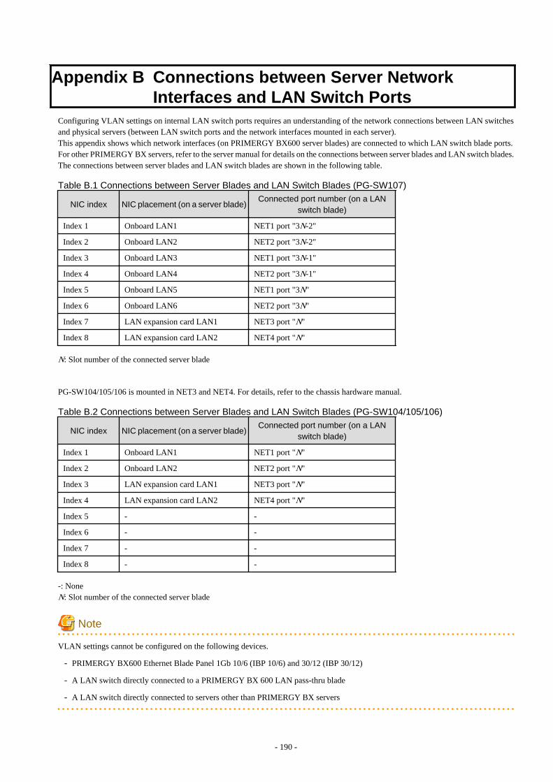
Appendix B Connections between Server NetworkInterfaces and LAN Switch Ports
Configuring VLAN settings on internal LAN switch ports requires an understanding of the network connections between LAN switchesand physical servers (between LAN switch ports and the network interfaces mounted in each server).This appendix shows which network interfaces (on PRIMERGY BX600 server blades) are connected to which LAN switch blade ports.For other PRIMERGY BX servers, refer to the server manual for details on the connections between server blades and LAN switch blades.The connections between server blades and LAN switch blades are shown in the following table.
Table B.1 Connections between Server Blades and LAN Switch Blades (PG-SW107)
NIC index NIC placement (on a server blade)Connected port number (on a LAN
switch blade)
Index 1 Onboard LAN1 NET1 port "3N-2"
Index 2 Onboard LAN2 NET2 port "3N-2"
Index 3 Onboard LAN3 NET1 port "3N-1"
Index 4 Onboard LAN4 NET2 port "3N-1"
Index 5 Onboard LAN5 NET1 port "3N"
Index 6 Onboard LAN6 NET2 port "3N"
Index 7 LAN expansion card LAN1 NET3 port "N"
Index 8 LAN expansion card LAN2 NET4 port "N"
N: Slot number of the connected server blade
PG-SW104/105/106 is mounted in NET3 and NET4. For details, refer to the chassis hardware manual.
Table B.2 Connections between Server Blades and LAN Switch Blades (PG-SW104/105/106)
NIC index NIC placement (on a server blade)Connected port number (on a LAN
switch blade)
Index 1 Onboard LAN1 NET1 port "N"
Index 2 Onboard LAN2 NET2 port "N"
Index 3 LAN expansion card LAN1 NET3 port "N"
Index 4 LAN expansion card LAN2 NET4 port "N"
Index 5 - -
Index 6 - -
Index 7 - -
Index 8 - -
-: NoneN: Slot number of the connected server blade
Note
VLAN settings cannot be configured on the following devices.
- PRIMERGY BX600 Ethernet Blade Panel 1Gb 10/6 (IBP 10/6) and 30/12 (IBP 30/12)
- A LAN switch directly connected to a PRIMERGY BX 600 LAN pass-thru blade
- A LAN switch directly connected to servers other than PRIMERGY BX servers
- 190 -

LAN switch blade product names may differ between countries.This appendix refers to the product names used in Japan.The following table shows product references often used in other countries.
Reference Product Name
PG-SW104PRIMERGY BX600 Switch Blade (1Gbps)PRIMERGY BX600 Ethernet Switch 1GB 10/6 (SB9)
PG-SW105PRIMERGY BX600 Switch Blade (10Gbps)PRIMERGY BX600 Ethernet Switch 1GB 10/6+2 (SB9)
PG-SW106Cisco Catalyst Blade Switch 3040PRIMERGY BX600 Ethernet Switch 1GB 10/6 (Cisco CBS 3040)
PG-SW107PRIMERGY BX600 Switch Blade (1Gbps)PRIMERGY BX600 Ethernet Switch 1GB 30/12 (SB9F)
- 191 -

Appendix C Port ListThis appendix explains the ports used by Resource Coordinator VE.
The following figure shows the connection configuration of Resource Coordinator VE components.
Figure C.1 Connection Configuration
Resource Coordinator VE ports should be set up during the system configuration of each related server.For details on how to configure the ports used by Resource Coordinator VE, refer to "6.3.1.2 Changing Port Numbers" or "6.3.2.6 ChangingPort Numbers".If any of those ports is already used by another service, allocate a different port number.
The following tables show the port numbers used by Resource Coordinator VE. Communications should be allowed for each of theseports for Resource Coordinator VE to operate properly.
Table C.1 Admin Client
FunctionOverview
Source Destination
ProtocolServer Service Port
Change
Server Service PortChan
ge
RC Console
Adminclient
-Variablevalue
Notpossible
Adminserver
rcxweb 23461Possible
tcpServerViewOperationsManager (*1)
http 3169 Notpossiblehttps 3170
*1: Required for PRIMERGY servers.
Table C.2 Firewall
FunctionOverview
DirectionSource Destination
ProtocolServer Port Server Port
RC Console
One-way Admin clientVariablevalue
Admin server
23461
tcpServerViewOperationsManager (*1)
3169
3170
*1: Required for PRIMERGY servers.
- 192 -

Table C.3 Admin Server
FunctionOverview
Source Destination
ProtocolServer Service Port
Change
Server Service PortChan
ge
RC Console
Adminclient
-Variablevalue
Notpossible
Admin server
rcxweb 23461Possible
tcpServerViewOperationsManager (*1)
http 3169 Notpossiblehttps 3170
Internal controlAdminserver
-Variablevalue
-
Admin server
(*2)
- (*3) 3172Notpossible
tcp
-Variablevalue
- nfdomain 23457Possible
tcp
-Variablevalue
- rcxmgr 23460Possible
tcp
-Variablevalue
- rcxtask 23462Possible
tcp
-Variablevalue
-
rcxmongrel1
23463Possible
tcp
rcxmongrel2
23464Possible
tcp
rcxdb 23465Possible
tcp
Monitoringand controllingresources
Adminserver
-Variablevalue
-Managedserver(Physical OS)
nfagent 23458Possible
tcp
-Variablevalue
- Servermanagementunit(managementblade)
snmp 161Notpossible
udp
-Variablevalue
- snmptrap 162Notpossible
udp
-Variablevalue
-
Servermanagementunit (RemoteManagementController)
ipmi 623Notpossible
udp
-Variablevalue
- snmptrap 162Notpossible
udp
-Variablevalue
- telnet 23Notpossible
tcp
ServerViewAgent (*1)
Adminserver
-Variablevalue
-Managedserver
snmp 161Notpossible
tcpudp
Managedserver
-Variablevalue
- Admin server snmptrap 162Notpossible
udp
- 193 -

FunctionOverview
Source Destination
ProtocolServer Service Port
Change
Server Service PortChan
ge
Backup,restore,cloning
Adminserver
- 4972Notpossible
Managedserver
- 4973Notpossible
udp
Managedserver
- 4973Notpossible
Admin server
- 4972Notpossible
udp
bootpc 68Notpossible
bootps 67Notpossible
udp
-Variablevalue
- pxe 4011Notpossible
udp
-Variablevalue
- tftp 69Notpossible
udp
Adminserver
-Variablevalue
- Admin server - 4971Notpossible
tcp
Backup,cloning(collection)
Managedserver
-
14974 to14989(*4)4974 to4989(*5)
- Admin server -
14974to14989(*4)4974 to4989(*5)
- udp
Restore,cloning(deployment)
Managedserver
-Variablevalue
- Admin server -
14974to14989(*4)4974 to4989(*5)
-tcpudp
Monitoringserver powerstatus
Adminserver
- - -Managedserver
- - - ICMP (*6)
VMware ESX/ESXi, vCenterServer (*7)
Adminserver
-Variablevalue
-Managedserver,vCenter Server
- 443Notpossible
tcp
System CenterVirtualMachineManager
Adminserver
-Variablevalue
-
System CenterVirtualMachineManager
- 80Notpossible
tcpWinRM 443
OpenDSAdminserver
-Variablevalue
- OpenDS ldaps 1474Possible
tcp
ActiveDirectory
Adminserver
-Variablevalue
-ActiveDirectory
ldaps 636Possible
tcp
Discover LANswitches
Adminserver
- - - LAN switch - - - ICMP
- 194 -
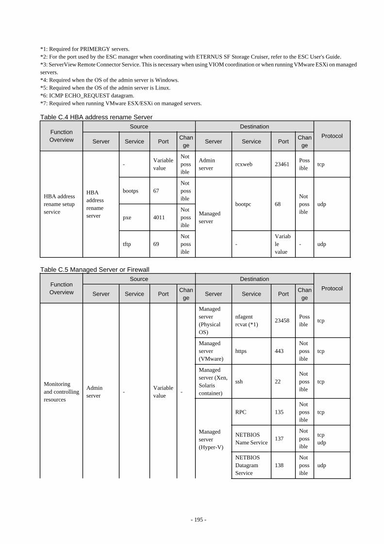
*1: Required for PRIMERGY servers.*2: For the port used by the ESC manager when coordinating with ETERNUS SF Storage Cruiser, refer to the ESC User's Guide.*3: ServerView Remote Connector Service. This is necessary when using VIOM coordination or when running VMware ESXi on managedservers.*4: Required when the OS of the admin server is Windows.*5: Required when the OS of the admin server is Linux.*6: ICMP ECHO_REQUEST datagram.*7: Required when running VMware ESX/ESXi on managed servers.
Table C.4 HBA address rename Server
FunctionOverview
Source Destination
ProtocolServer Service Port
Change
Server Service PortChan
ge
HBA addressrename setupservice
HBAaddressrenameserver
-Variablevalue
Notpossible
Adminserver
rcxweb 23461Possible
tcp
bootps 67Notpossible
Managedserver
bootpc 68Notpossible
udp
pxe 4011Notpossible
tftp 69Notpossible
-Variablevalue
- udp
Table C.5 Managed Server or Firewall
FunctionOverview
Source Destination
ProtocolServer Service Port
Change
Server Service PortChan
ge
Monitoringand controllingresources
Adminserver
-Variablevalue
-
Managedserver(PhysicalOS)
nfagentrcvat (*1)
23458Possible
tcp
Managedserver(VMware)
https 443Notpossible
tcp
Managedserver (Xen,Solariscontainer)
ssh 22Notpossible
tcp
Managedserver(Hyper-V)
RPC 135Notpossible
tcp
NETBIOSName Service
137Notpossible
tcpudp
NETBIOSDatagramService
138Notpossible
udp
- 195 -

FunctionOverview
Source Destination
ProtocolServer Service Port
Change
Server Service PortChan
ge
NETBIOSSessionService
139Notpossible
tcp
SMB 445Notpossible
tcpudp
ServerViewAgent (*2)
Adminserver
-Variablevalue
-Managedserver
snmp 161Notpossible
tcpudp
Managedserver
-Variablevalue
-Adminserver
snmptrap 162Notpossible
udp
Backup,restore,cloning
Adminserver
- 4972Notpossible
Managedserver
- 4973Notpossible
udp
Managedserver
- 4973Notpossible Admin
server
- 4972Notpossible
udp
-Variablevalue
- tftp 69Notpossible
udp
HBA addressrename setupservice
Managedserver
bootpc 68Notpossible
HBAaddressrenameserver
bootps 67Notpossible
udp
pxe 4011Notpossible
udp
-Variablevalue
- tftp 69Notpossible
udp
VMware ESX/ESXi (*3)
Adminserver
-Variablevalue
-Managedserver
- 443Notpossible
tcp
*1: Required for SPARC Enterprise servers.*2: Required for PRIMERGY servers.*3: Required when running VMware ESX/ESXi on managed servers.
- 196 -

Table C.6 VM Management Server
FunctionOverview
Source DestinationProtocol
Server Service Port Change Server Service Port Change
vCenterServer
Adminserver
-Variablevalue
-vCenterServer
- 443Notpossible
tcp
SystemCenterVirtualMachineManager
Adminserver
-Variablevalue
-
SystemCenterVirtualMachineManager
- 80
Notpossible
tcpWinRM 443
Table C.7 Directory Service Server
FunctionOverview
Source DestinationProtocol
Server Service Port Change Server Service Port Change
OpenDSAdminserver
-Variablevalue
- OpenDS ldaps 1474 Possible tcp
ActiveDirectory
Adminserver
-Variablevalue
-ActiveDirectory
ldaps 636 Possible tcp
- 197 -

Appendix D Format of CSV System Configuration FilesThis appendix explains the format of the CSV system configuration files used by Resource Coordinator's pre-configuration function.
D.1 Obtaining the System Configuration File (CSV Format)The system configuration files can be obtained as follows.
- From the selection window of the Resource Coordinator VE CD-ROM [Windows]
Place the Resource Coordinator VE CD-ROM in a CD-ROM drive. This will display the selection window shown below. Select "Tool"and click "System Configuration Template (CSV format)". The CSV file will be opened from the associated application (such asExcel). Check the file content and save it.
Figure D.1 Selection Window
Information
If the above window does not open, execute "RcSetup.exe" from the CD-ROM drive.
- From the Resource Coordinator VE CD-ROM
Insert the Resource Coordinator VE CD-ROM in a CD-ROM drive and copy the following file.
[Windows]CD_drive\template\en\template.csv
[Linux]CD_mount_point/template/en/template.csv
- 198 -

- From the RC console
The System Configuration Template can be obtained from a Resource Coordinator VE installation.
1. Open and log in to the RC console according to the instructions given in "5.3 RC Console".
2. Select [File]-[Download Template]-[CSV Format] from the RC console menu.
3. Click <Save> in the [File Download] dialog.
4. Specify the destination directory and the file name, then click <Save>.
D.2 File FormatThe system configuration files (CSV format) used for pre-configuration are comma (",") delimited.The format of each line is given below:
- File format definition
The first line of the file must begin with the following:
RCXCSV,V3.4
Point
Resource Coordinator VE can import the following system configuration file formats.
- RCXCSV,V1.0
- RCXCSV,V2.0
- RCXCSV,V3.0
- RCXCSV,V3.1
- RCXCSV,V3.2
- RCXCSV,V3.3
- RCXCSV,V3.4
However, system definition files are always exported in the most recent format: importing a file in an older format and re-exportingit will produce a file in the latest format.
Note
For details about previous system configuration file versions, refer to their corresponding manuals (see below).
- RCXCSV V1.0
Refer to the "Systemwalker Resource Coordinator Virtual server Edition V13.2 Setup Guide".
- RCXCSV V2.0
Refer to the "Systemwalker Resource Coordinator Virtual server Edition V13.3 Setup Guide".
Although each RCXCSV version has a different format, those formats are retro-compatible (newer formats include all the informationdefined in older formats).As detailed below, some sections (described in "D.3 Resource Definitions") are only available with the latest format(s).
- RCXCSV V2.0 and later
"LanSwitchNet", "ServerAgent", "ServerVMHost", "PowerDevice", "Memo"
- RCXCSV V3.0 and later
"VMManager"
- 199 -

- RCXCSV V3.1
"SPARCEnterprise"
- RCXCSV V3.2
"PRIMERGYPartitionModelChassis", "PRIMERGYPartitionModelServer"
- RCXCSV V3.1
"Subnet", "SPARCEnterprisePartitionModelChassis", "SPARCEnterprisePartitionModelServer", "MonitorSetting"
- RCXCSV V3.4
"VIOManager"
- Comments
The following lines are assumed to be comments and are skipped:
- Lines that begin with the symbol ("#")
Example
#Development environmentdefinition
- Lines that consist of only blank spaces (" "), tab characters, or linefeed code
- Lines that contain only commas (",")
- Unrecognized resource definition
- Resource definitions
Create the resource definition using the following format. Describe the same type of resource in the same section.
- Resource definition format
[Section name]Section headerOperation column, Parameter [,parameter]...
- Section name
This describes the resource type.
- Section header
This describes the parameter type unique to the resource.
Note
Do not enter any comments between the section name and section header.
- Operation Column
This describes the operation type for the resource. The following characters can be used in the operation column.
"new": register"change": change"-": do nothing
- Parameter
This describes the parameter value to be set.
- 200 -

Note
The order of operation and parameter columns should follow the order defined in "Section header" under "D.3 ResourceDefinitions".
Allowed Characters
For details on the characters allowed for each resource definition, refer to "D.3 Resource Definitions". Optional parameters can beomitted by using hyphens ("-").However, hyphens ("-") are seen as valid characters for user names, passwords, and SNMP communities. Note that if extra commas(",") are added to the end of a line, those will be simply ignored without errors.
Backslashes ("\") and double quotations ( " ) will be displayed differently in the RC console from how they appear in the systemconfiguration file.Refer to the following table for details on such differences.
Table D.1 Differences between system configuration files' contents and display in the RC console
Content of a system configuration file (CSV) Display in the RC console
\\ \
\n Line break
"" "
, (*1) ,
*1: The whole value must be enclosed by double quotations ( " ).
Example
- CSV content
"a\nb,\\n"
- Display in the RC console
ab,\n
Order of section definition
Section order and section name are shown below.Moreover, the section definition order is fixed.
Table D.2 Section order and section names
Order Section name
1 Subnet
2 VIOManager
3 Chassis
4 PRIMERGYPartitionModelChassis
5 SPARCEnterprisePartitionModelChassis
6 LanSwitch
7 LanSwitchNet
8 Server
9 SPARCEnterprise
- 201 -
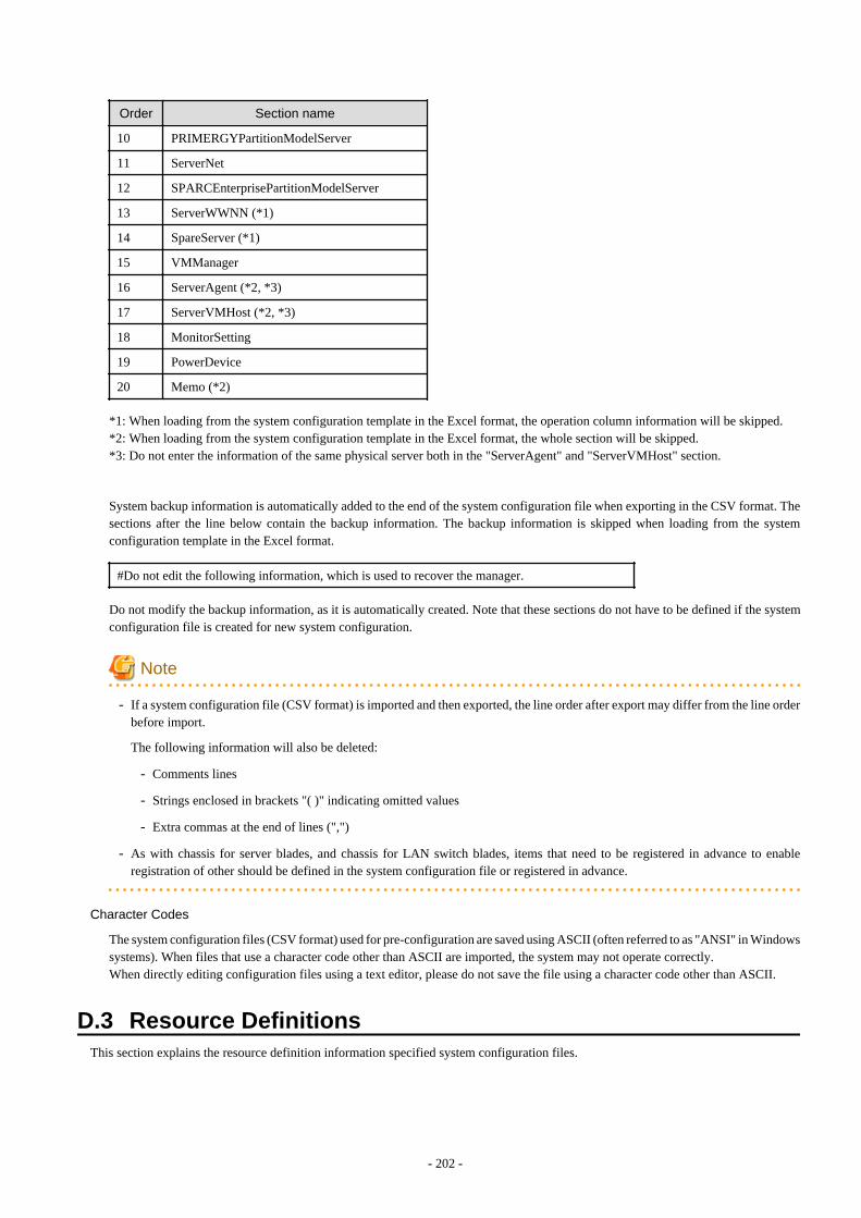
Order Section name
10 PRIMERGYPartitionModelServer
11 ServerNet
12 SPARCEnterprisePartitionModelServer
13 ServerWWNN (*1)
14 SpareServer (*1)
15 VMManager
16 ServerAgent (*2, *3)
17 ServerVMHost (*2, *3)
18 MonitorSetting
19 PowerDevice
20 Memo (*2)
*1: When loading from the system configuration template in the Excel format, the operation column information will be skipped.*2: When loading from the system configuration template in the Excel format, the whole section will be skipped.*3: Do not enter the information of the same physical server both in the "ServerAgent" and "ServerVMHost" section.
System backup information is automatically added to the end of the system configuration file when exporting in the CSV format. Thesections after the line below contain the backup information. The backup information is skipped when loading from the systemconfiguration template in the Excel format.
#Do not edit the following information, which is used to recover the manager.
Do not modify the backup information, as it is automatically created. Note that these sections do not have to be defined if the systemconfiguration file is created for new system configuration.
Note
- If a system configuration file (CSV format) is imported and then exported, the line order after export may differ from the line orderbefore import.
The following information will also be deleted:
- Comments lines
- Strings enclosed in brackets "( )" indicating omitted values
- Extra commas at the end of lines (",")
- As with chassis for server blades, and chassis for LAN switch blades, items that need to be registered in advance to enableregistration of other should be defined in the system configuration file or registered in advance.
Character Codes
The system configuration files (CSV format) used for pre-configuration are saved using ASCII (often referred to as "ANSI" in Windowssystems). When files that use a character code other than ASCII are imported, the system may not operate correctly.When directly editing configuration files using a text editor, please do not save the file using a character code other than ASCII.
D.3 Resource DefinitionsThis section explains the resource definition information specified system configuration files.
- 202 -

Admin LAN Subnet Data
- Section name
Enter [Subnet] as the section name.
- Section header
operation
Enter the desired operation for the current line. Enter a hyphen ("-") to skip this line.
subnet_name
Enter the subnet name.Enter up to 16 characters, including alphanumeric characters, underscores ("_"), hyphens ("-"), or periods ("."). This name shouldstart with an alphabet character.
network_address
Enter the network address for the subnet used as the admin LAN.Enter valid values for the network address.
subnet_mask
Enter valid values for the subnet mask.
gateway
Enter the settings for the gateway used for communication with the admin server on the admin LAN.
VIOM Data
- Section name
Enter [VIOManager] as the section name.
- Section header
operation
Enter the desired operation for the current line. Enter a hyphen ("-") to skip this line.
name
Specify "VIOM".
ip_address
Enter the IP address of the terminal on which VIOM is installed.Specify "127.0.0.1".
login_name
Enter the name of a VIOM user account.When specifying a domain, use the following syntax: "domain_name\user_name".
login_passwd
Enter the password of the above VIOM user account.
passwd_enc
Enter "plain" if the password character string is plain, and enter "encrypted" if the password is encrypted.
Chassis Data
- Section name
Enter [Chassis] as the section name.
- 203 -

- Section header
operation
Enter the desired operation for the current line. Enter a hyphen ("-") to skip this line.
chassis_name
Enter the name that will be used to identify the chassis.Enter up to 10 characters, including alphanumeric characters and hyphens ("-"). This name should start with an alphabet character.
Note
Chassis names should be unique between all chassis. Names are not case-sensitive.
ip_address
Enter the same IP address as that set on the management blade.Enter a string of numeric values (between 0 and 255) and periods.
Note
IP addresses should be unique between all resources.
snmp_community_name
Enter the same SNMP community (read-write permission) as that set on the management blade.Enter up to 32 characters, including alphanumeric characters, underscores ("_"), and hyphens ("-").
PRIMERGY Partition Model Chassis Data
- Section name
Enter [PRIMERGYPartitionModelChassis] as the section name.
- Section header
operation
Enter the desired operation for the current line. Enter a hyphen ("-") to skip this line.
chassis_name
Enter the name that will be used to identify the chassis.Enter up to 10 characters, including alphanumeric characters and hyphens ("-"). This name should start with an alphabet character.
Note
Chassis names should be unique between all chassis.Names are not case-sensitive.
ip_address
Enter the same IP address as that set on the management board.Enter a string of numeric values (between 0 and 255) and periods.
Note
IP addresses should be unique between all resources.
- 204 -

snmp_community_name
Enter the same SNMP community (read-write permission) as that set on the management board.Enter up to 32 characters, including alphanumeric characters, underscores ("_"), and hyphens ("-").
mgmt_user_name
Enter the name of a remote server management user account with administrative privileges.This user name must be between 8 and 16 alphanumeric characters long.
mgmt_passwd
Enter the password of the remote server management account.This password must be between 8 and 16 alphanumeric characters long.
mgmt_passwd_enc
Enter "plain" if mgmt_passwd is plain text, or "encrypted" if mgmt_passwd is encrypted.
SPARC Enterprise M4000/M5000/M8000/M9000 Chassis Data
- Section name
Enter [SPARCEnterprisePartitionModelChassis] as the section name.
- Section header
operation
Enter the desired operation for the current line. Enter a hyphen ("-") to skip this line.
chassis_name
Enter the name that will be used to identify the chassis.Enter up to 10 characters, including alphanumeric characters and hyphens ("-"). This name should start with an alphabet character.
Note
Chassis names should be unique between all chassis.Names are not case-sensitive.
ip_address
Enter the same IP address as that configured on the XSCF.Enter a string of numeric values (between 0 and 255) and periods.
Note
IP addresses should be unique between all resources.
snmp_community_name
Enter the name of a SNMP community (with read permission) configured on this server's remote management controller (XSCF).Enter up to 32 characters, including alphanumeric characters, underscores ("_"), and hyphens ("-").
mgmt_user_name
Enter the name of a remote management controller (XSCF) user account with administrative privileges ("platadm" privileges).Enter a string of up to 31 alphanumerical characters, hyphens ("-"), and underscores ("_"). This name must start with an alphabetcharacter.
- 205 -

mgmt_passwd
Enter the password of the remote management controller (XSCF) user account.Enter up to 32 characters, including alphanumeric characters, blank spaces (" "), and any of the following symbols."!", "@", "#", "$", "%", "^", "&", "*", "[", "]", "{", "}", "(", ")", "-", "+", "=", "~", ",", ">", "<", "/", "'", "?", ";", ":"
mgmt_passwd_enc
Enter "plain" if mgmt_passwd is plain text, or "encrypted" if mgmt_passwd is encrypted.
LAN Switch Blade Data
- Section name
Enter [LanSwitch] as the section name.
- Section header
operation
Enter the desired operation for the current line. Enter a hyphen ("-") to skip this line.
chassis_name
Enter the chassis name (the value of "chassis_name" in the [Chassis] section).
slot_no
Enter the slot number where the LAN switch blade is installed. Enter a number between 1 and 8.
switch_name
Enter the name to assign to this LAN switch blade.Enter up to 15 characters, including alphanumeric characters, underscores ("_"), and hyphens ("-").
Note
LAN switch blade names should be unique between all LAN switch blades. The names are case-sensitive.
ip_address
Enter the same IP address as that set on the LAN switch blade.Enter a string of numeric values (between 0 and 255) and periods.
Note
IP addresses should be unique between all resources.
snmp_community_name
Enter the same SNMP community (read-only permission) as that set on the LAN switch blade.Enter a string of up to 32 alphanumerical characters, underscores ("_"), and hyphens ("-").
user_name
Enter the name of the user account used to remotely log into the LAN switch blade.Enter up to 64 characters, including alphanumeric characters (upper or lower case), underscores ("_"), and hyphens ("-").
passwd
Enter the password of the above user account (for remote login).Enter a string of up to 80 alphanumerical characters and symbols (ASCII character codes: 0x20, 0x21 or 0x23 to 0x7e) and nodouble-quotations ("). Passwords entered in this field are seen as plain text passwords.
passwd_enc
Enter "plain" if the password character string is plain, and enter "encrypted" if the password is encrypted.
- 206 -

privileged_passwd
Enter the admin password of the above user account.Enter a string of up to 80 alphanumerical characters and symbols (ASCII character codes: 0x20, 0x21 or 0x23 to 0x7e) and nodouble-quotations ("). Passwords entered in this field are seen as plain text passwords.
privileged_passwd_enc
Enter "plain" if the privileged password character string is plain text, and enter "encrypted" if the password is encrypted.
product_name
Enter the model of the LAN switch blade. Note that if a hyphen ("-") is entered, it is treated as "BX600 GbE Switch Blade 30/12".One of the following models can be entered.
- PY CB Eth Switch/IBP 1Gb 36/12
- PY CB Eth Switch/IBP 1Gb 36/8+2
- PY CB Eth Switch/IBP 1Gb 18/6
- PY CB Eth Switch/IBP 10Gb 18/8
- BX600 GbE Switch Blade 30/12
- PRIMERGY BX600 GbE Switch 16/2x10Gb
- PRIMERGY BX600 GbE Switch 16x1Gb
- Cisco Catalyst Blade Switch 3040
VLAN Data for LAN Switch Blades
- Section name
Enter [LanSwitchNet] as the section name.
- Section header
operation
Enter the desired operation for the current line. Enter a hyphen ("-") to skip this line.
chassis_name
Enter the chassis name (the value of "chassis_name" in the [Chassis] section).
port_no
Enter the port number of an external LAN switch blade port. Enter numeric characters. The port number that can be specified isdifferent depending on the model type. For details, refer to the manual of the LAN switch blade to be used.
vlan_id (optional)
Enter the VLAN ID and tag type ("/T" for tagged or "/U" for untagged) to be assigned to the specified LAN switch blade port.Enter a VLAN ID followed by tag types. To specify multiple VLAN IDs, separate each set of VLAN settings using semicolons(";"). Both tagged ("/T") and untagged ("/U") VLAN IDs can be used together, but only one untagged ("/U") type is allowed.
Example
10/U10/U;20/T;30/T10/T;20/T
- 207 -
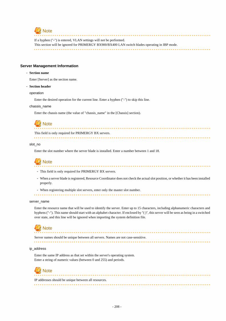
Note
If a hyphen ("-") is entered, VLAN settings will not be performed.This section will be ignored for PRIMERGY BX900/BX400 LAN switch blades operating in IBP mode.
Server Management Information
- Section name
Enter [Server] as the section name.
- Section header
operation
Enter the desired operation for the current line. Enter a hyphen ("-") to skip this line.
chassis_name
Enter the chassis name (the value of "chassis_name" in the [Chassis] section).
Note
This field is only required for PRIMERGY BX servers.
slot_no
Enter the slot number where the server blade is installed. Enter a number between 1 and 18.
Note
- This field is only required for PRIMERGY BX servers.
- When a server blade is registered, Resource Coordinator does not check the actual slot position, or whether it has been installedproperly.
- When registering multiple slot servers, enter only the master slot number.
server_name
Enter the resource name that will be used to identify the server. Enter up to 15 characters, including alphanumeric characters andhyphens ("-"). This name should start with an alphabet character. If enclosed by "( )", this server will be seen as being in a switchedover state, and this line will be ignored when importing the system definition file.
Note
Server names should be unique between all servers. Names are not case-sensitive.
ip_address
Enter the same IP address as that set within the server's operating system.Enter a string of numeric values (between 0 and 255) and periods.
Note
IP addresses should be unique between all resources.
- 208 -

mac_address
Enter the MAC address of the admin LAN network interface: NIC1 (Index1).Enter a string delimited by hyphens ("-") or colons (":") ("xx-xx-xx-xx-xx-xx" or "xx:xx:xx:xx:xx:xx").
second_mac_address
Enter the MAC address of the network interface used for the HBA address rename setup service or for admin LAN redundancy.
The second network interface (Index 2) should be used.
Enter a string delimited by hyphens ("-") or colons (":") ("xx-xx-xx-xx-xx-xx" or "xx:xx:xx:xx:xx:xx").
Note
- This field can be omitted in the following cases.
- When not using the HBA address rename setup service
- When not using GLS for admin LAN redundancy on the managed server
- For a spare server whose primary servers are not using admin LAN redundancy
- The "second_mac_address" header is the equivalent of the "hbaar_mac_address" header defined in RCXCSV V3.0.
"hbaar_mac_address" can only be used when "RCXCSV,V3.0" is specified at the top of the imported system configurationfile.
However, this header is automatically changed to "second_mac_address" when exporting a new system configuration file.
snmp_community_name
Enter the name of the SNMP community (read permission) assigned to this server.Enter up to 32 characters, including alphanumeric characters, underscores ("_"), and hyphens ("-").
Note
This field is only required when using the HBA address rename setup service.
ipmi_ip_address
Enter the IP address of this server's remote management controller.Enter a string of numeric values (between 0 and 255) and periods.
Note
IP addresses should be unique between all resources.
ipmi_user_name
Enter the name of a remote management controller user account with administrative privileges.Enter a string of up to 16 alphanumerical characters and symbols (ASCII character codes: 0x20 to 0x7e).
Note
If the name of the current administrator account on the remote management controller is longer than 16 characters, either createa new account or rename the current account (within 16 characters).
- 209 -

ipmi_passwd
Enter the password of the remote management controller user account.Enter a string of up to 16 alphanumerical characters and symbols (ASCII character codes: 0x20 to 0x7e).This field can be omitted if no password has been set for this user account.
Note
If the password of the current administrator account on the remote management controller is longer than 16 characters, either createa new account or change its password (within 16 characters).
ipmi_ passwd_enc
Enter "plain" if the password character string is plain, and enter "encrypted" if the password is encrypted.
admin_lan1_nic_number
The index of the NIC to use for the admin LAN.Enter a number (1 or larger).
Note
This field is only required for PRIMERGY BX servers.
admin_lan2_nic_number
The Index number of NICs used for the HBA address rename setup service or for admin LAN redundancy.Enter a number (1 or larger).For the following cases, enter a hyphen ("-").
- When not using the HBA address rename setup service
- When redundancy of the admin LAN for managed servers does not use GLS
- When not using as the spare server of a managed server with redundancy configured
Note
This field is only required for PRIMERGY BX servers.
SPARC Enterprise Server Data
- Section name
Enter [SPARCEnterprise] as the section name.
- Section header
operation
Enter the desired operation for the current line. Enter a hyphen ("-") to skip this line.
server_name
Enter the resource name that will be used to identify the server. Enter up to 15 characters, including alphanumeric characters andhyphens ("-"). This name should start with an alphabet character.
ip_address
Enter the same IP address as that set within the server's operating system. Enter a string of numeric values (between 0 and 255)and periods.
- 210 -

mgmt_snmp_community_name
Enter the name of a SNMP community (with read permission) configured on this server's remote management controller (ILOM/XSCF).Enter up to 32 characters, including alphanumeric characters, underscores ("_"), and hyphens ("-").
mgmt_ip_address
Enter the IP address of this server's remote management controller (ILOM/XSCF).Enter a string of numeric values (between 0 and 255) and periods.
Note
IP addresses should be unique between all resources.
mgmt_protocol
Enter the type of the remote management controller (ILOM/XSCF) to manage servers.Enter "XSCF" for M3000 series, and enter "ILOM" for T series.
mgmt_user_name
Enter the user name (For ILOM, Admin privileges, and for XSCF, platadm privileges) of a remote management controller tomanage servers (ILOM/XSCF).For XSCF, enter up to 31 characters, including alphanumeric characters, underscores ("_"), or hyphens ("-"). This name shouldstart with an alphabet character.For ILOM, enter between 4 and 16 characters, including alphanumeric characters, underscores ("_"), or hyphens ("-"). This nameshould start with an alphabet character.
mgmt_passwd
Enter the password of the remote management controller (ILOM/XSCF) to manage a server.
For XSCF, enter up to 32 alphanumerical characters and spaces (" "), and any of the following symbols. For ILOM, enter 8 to 16alphanumerical characters and spaces (" "), and any of the following symbols.
"!", "@", "#", "$", "%", "^", "&", "*", "[", "]", "{", "}", "(", ")", "-", "+", "=", "~", ",", ">", "<", "/", "'", "?", ";", ":"
mgmt_passwd_enc
Enter "plain" if mgmt_passwd is plain text, or "encrypted" if mgmt_passwd is encrypted.
PRIMERGY Partition Model Server Data
- Section name
Enter [PRIMERGYPartitionModelServer] as the section name.
- Section header
operation
Enter the desired operation for the current line. Enter a hyphen ("-") to skip this line.
chassis_name
Enter the chassis name (the value of "chassis_name" in the [PRIMERGYPartitionModelChassis] section).
partition_no
The number of a partition. Enter a number between 0 and 3.
server_name
Enter the resource name that will be used to identify the server. Enter up to 15 characters, including alphanumeric characters andhyphens ("-"). This name should start with an alphabet character. If enclosed by "( )", this server will be seen as being in a switchedover state, and this line will be ignored when importing the system definition file.
- 211 -

Note
Server names should be unique between all servers. Names are not case-sensitive.
ip_address
Enter the same IP address as that set within the server's operating system.Enter a string of numeric values (between 0 and 255) and periods.
Note
IP addresses should be unique between all resources.
boot_option
Specify the boot option configured from BIOS when installing the OS.
When a legacy boot was installed, enter "legacy", and when UEFI was installed, enter "uefi".
Note
[Linux]The boot option specification will become disabled, and always be treated as "legacy".
Server Blade VLAN Data
- Section name
Enter [ServerNet] as the section name.
- Section header
operation
Enter the desired operation for the current line. Enter a hyphen ("-") to skip this line.
server_name
Enter the server name (the value of "server_name" in the [Server] section).
nic_no
This is the index number of the server blade's network interface. Enter a number between 1 and 12.
vlan_id (optional)
Enter the VLAN ID and tag type ("/T" or "/U") to be assigned to the LAN switch blade port connected to this server's networkinterface.Enter a VLAN ID followed by tag types. To specify multiple VLAN IDs, separate each set of VLAN settings using semicolons(";"). Both tagged ("/T") and untagged ("/U") VLAN IDs can be used together, but only one untagged ("/U") type is allowed.
Example
10/U10/U;20/T;30/T10/T;20/T
- 212 -

Note
If a hyphen ("-") is entered, VLAN settings will not be performed.
Use the following NIC indexes to specify LAN expansion cards (if any was mounted).
- PRIMERGY BX600 servers
7, 8
- PRIMERGY BX900/BX400 servers
5 to 12
This section will be ignored for PRIMERGY BX900/BX400 LAN switch blades operating in IBP mode.
SPARC Enterprise M4000/M5000/M8000/M9000 Server Data
- Section name
Enter [SPARCEnterprisePartitionModelServer] as the section name.
- Section header
operation
Enter the desired operation for the current line. Enter a hyphen ("-") to skip this line.
chassis_name
Enter the chassis name (the "chassis_name" in the [SPARCEnterprisePartitionModelChassis] section).
partition_no
The number of a partition. Enter a number between 0 and 23.
server_name
Enter the resource name that will be used to identify the server. Enter up to 15 characters, including alphanumeric characters andhyphens ("-"). This name should start with an alphabet character.
Note
Server names should be unique between all servers.Names are not case-sensitive.
ip_address
Enter the same IP address as that set within the server's operating system.Enter a string of numeric values (between 0 and 255) and periods.
Note
IP addresses should be unique between all resources.
HBA address rename information of a server
- Section name
Enter [ServerWWNN] as the section name.
- 213 -
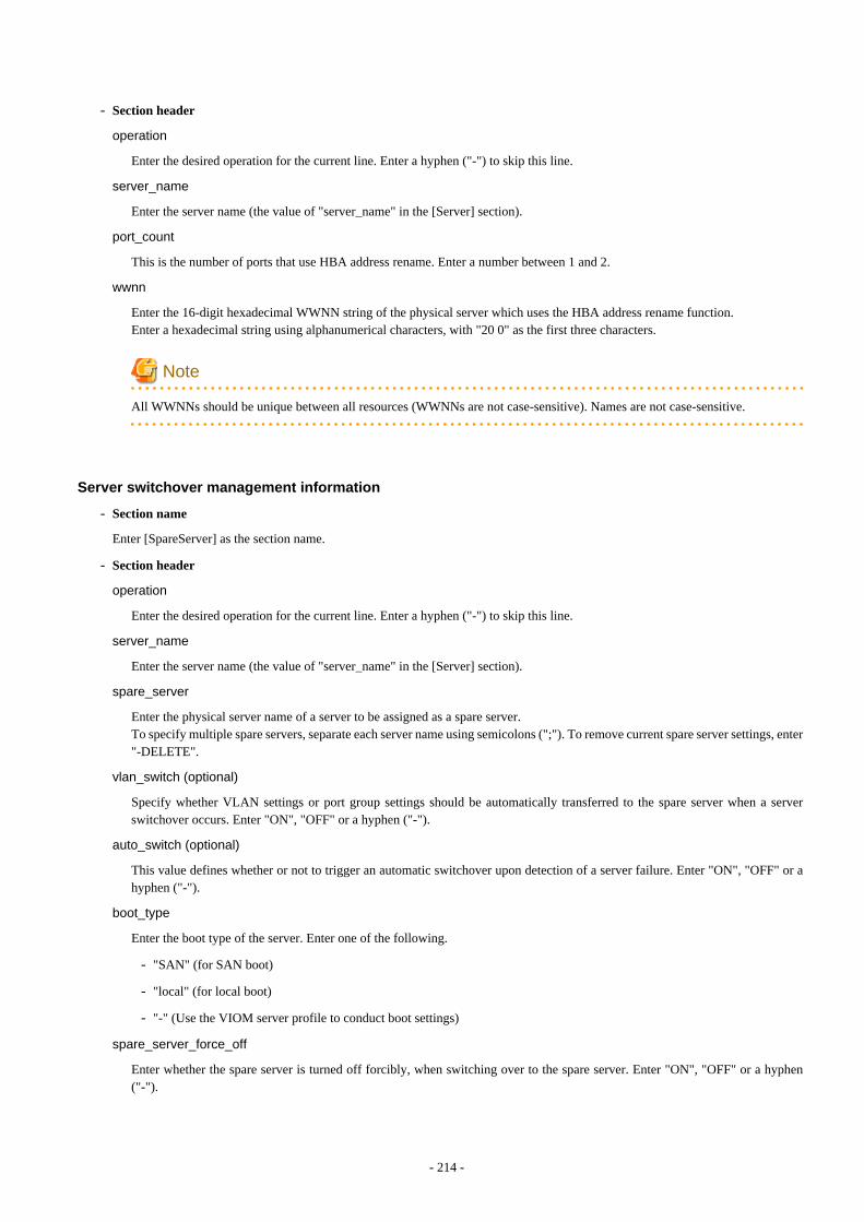
- Section header
operation
Enter the desired operation for the current line. Enter a hyphen ("-") to skip this line.
server_name
Enter the server name (the value of "server_name" in the [Server] section).
port_count
This is the number of ports that use HBA address rename. Enter a number between 1 and 2.
wwnn
Enter the 16-digit hexadecimal WWNN string of the physical server which uses the HBA address rename function.Enter a hexadecimal string using alphanumerical characters, with "20 0" as the first three characters.
Note
All WWNNs should be unique between all resources (WWNNs are not case-sensitive). Names are not case-sensitive.
Server switchover management information
- Section name
Enter [SpareServer] as the section name.
- Section header
operation
Enter the desired operation for the current line. Enter a hyphen ("-") to skip this line.
server_name
Enter the server name (the value of "server_name" in the [Server] section).
spare_server
Enter the physical server name of a server to be assigned as a spare server.To specify multiple spare servers, separate each server name using semicolons (";"). To remove current spare server settings, enter"-DELETE".
vlan_switch (optional)
Specify whether VLAN settings or port group settings should be automatically transferred to the spare server when a serverswitchover occurs. Enter "ON", "OFF" or a hyphen ("-").
auto_switch (optional)
This value defines whether or not to trigger an automatic switchover upon detection of a server failure. Enter "ON", "OFF" or ahyphen ("-").
boot_type
Enter the boot type of the server. Enter one of the following.
- "SAN" (for SAN boot)
- "local" (for local boot)
- "-" (Use the VIOM server profile to conduct boot settings)
spare_server_force_off
Enter whether the spare server is turned off forcibly, when switching over to the spare server. Enter "ON", "OFF" or a hyphen("-").
- 214 -
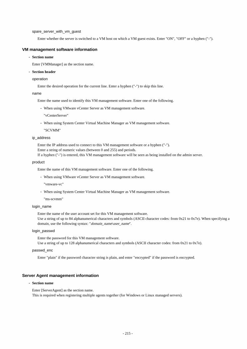
spare_server_with_vm_guest
Enter whether the server is switched to a VM host on which a VM guest exists. Enter "ON", "OFF" or a hyphen ("-").
VM management software information
- Section name
Enter [VMManager] as the section name.
- Section header
operation
Enter the desired operation for the current line. Enter a hyphen ("-") to skip this line.
name
Enter the name used to identify this VM management software. Enter one of the following.
- When using VMware vCenter Server as VM management software.
"vCenterServer"
- When using System Center Virtual Machine Manager as VM management software.
"SCVMM"
ip_address
Enter the IP address used to connect to this VM management software or a hyphen ("-").Enter a string of numeric values (between 0 and 255) and periods.If a hyphen ("-") is entered, this VM management software will be seen as being installed on the admin server.
product
Enter the name of this VM management software. Enter one of the following.
- When using VMware vCenter Server as VM management software.
"vmware-vc"
- When using System Center Virtual Machine Manager as VM management software.
"ms-scvmm"
login_name
Enter the name of the user account set for this VM management software.Use a string of up to 84 alphanumerical characters and symbols (ASCII character codes: from 0x21 to 0x7e). When specifying adomain, use the following syntax: "domain_name\user_name".
login_passwd
Enter the password for this VM management software.Use a string of up to 128 alphanumerical characters and symbols (ASCII character codes: from 0x21 to 0x7e).
passwd_enc
Enter "plain" if the password character string is plain, and enter "encrypted" if the password is encrypted.
Server Agent management information
- Section name
Enter [ServerAgent] as the section name.This is required when registering multiple agents together (for Windows or Linux managed servers).
- 215 -
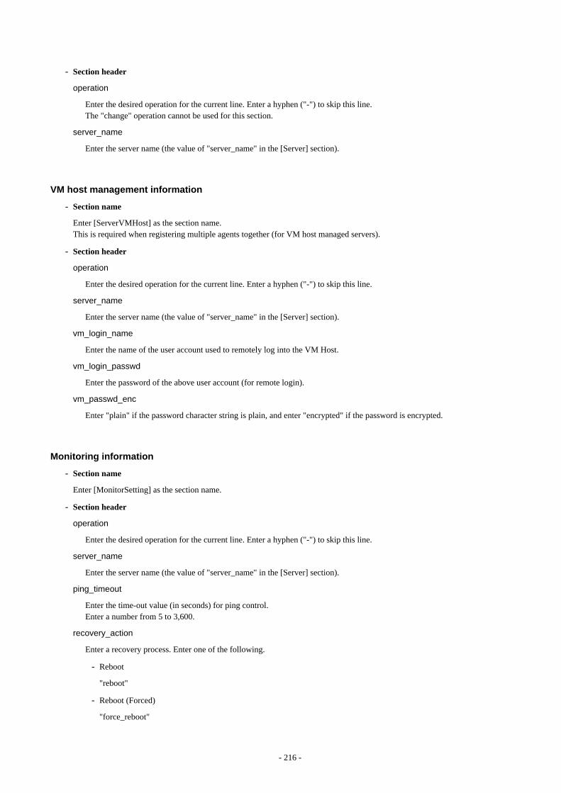
- Section header
operation
Enter the desired operation for the current line. Enter a hyphen ("-") to skip this line.The "change" operation cannot be used for this section.
server_name
Enter the server name (the value of "server_name" in the [Server] section).
VM host management information
- Section name
Enter [ServerVMHost] as the section name.This is required when registering multiple agents together (for VM host managed servers).
- Section header
operation
Enter the desired operation for the current line. Enter a hyphen ("-") to skip this line.
server_name
Enter the server name (the value of "server_name" in the [Server] section).
vm_login_name
Enter the name of the user account used to remotely log into the VM Host.
vm_login_passwd
Enter the password of the above user account (for remote login).
vm_passwd_enc
Enter "plain" if the password character string is plain, and enter "encrypted" if the password is encrypted.
Monitoring information
- Section name
Enter [MonitorSetting] as the section name.
- Section header
operation
Enter the desired operation for the current line. Enter a hyphen ("-") to skip this line.
server_name
Enter the server name (the value of "server_name" in the [Server] section).
ping_timeout
Enter the time-out value (in seconds) for ping control.Enter a number from 5 to 3,600.
recovery_action
Enter a recovery process. Enter one of the following.
- Reboot
"reboot"
- Reboot (Forced)
"force_reboot"
- 216 -

- Switchover
"switchover"
- Reboot and Switchover
"reboot_and_switchover"
- Reboot (Forced) and Switchover
"force_reboot_and_switchover"
reboot_count
Enter the number of times to reboot. Enter a number from 1 to 3.
Power Monitoring Device Data
- Section name
Enter [PowerDevice] as the section name.
- Section header
operation
Enter the desired operation for the current line. Enter a hyphen ("-") to skip this line.
device_name
Enter the name that will be used to identify the power monitoring device.Enter up to 15 characters, including alphanumeric characters and hyphens ("-"). This name should start with an alphabet character.
Note
Device names should be unique between all power monitoring devices. The names are case-sensitive.
ip_address
Enter the same IP address as that set on the power monitoring device.Enter a string of numeric values (between 0 and 255) and periods.
Note
IP addresses should be unique between all resources.
snmp_community_name
Enter the same SNMP community (read-only permission) as that set on the power monitoring device.Enter up to 32 characters, including alphanumeric characters, underscores ("_"), and hyphens ("-").
voltage
Enter the voltage (V) that is being supplied to the power monitoring device. Enter a number between 10 and 999.
Note
Power consumption data is calculated using the electrical current value obtained from the power monitoring device and its specifiedvoltage.
comment (optional)
Enter any comments for the power monitoring device.Enter up to 128 alphanumeric characters or symbols (ASCII characters 0x20 to 0x7e).
- 217 -

Note
A line break is counted as one character. Use "Alt+Enter" to enter line breaks.
Memo
- Section name
Enter [Memo] as the section name.This is required when registering the labels, comments, and contact information (displayed in BladeViewer) using the pre-configurationfunction.
- Section header
operation
Enter the desired operation for the current line. Enter a hyphen ("-") to skip this line.
resource_type
Enter the type of the resource for which to set this memo. Enter one of the following.
- "physical_server" (when a physical server including a VM host is specified)
- "vm_guest" (when a VM guest is specified)
- "common" (when contact information is specified)
resource_name
Enter the name of the resource name for which to set this memo. Enter one of the following.
- Enter the server name (the value of "server_name" in the [ServerAgent] section) or the VM host name (the value of"server_name" in the [ServerVMHost] section) if the value of "resource_type" is "physical_server".
- Enter only the registered VM guest name if the value of "resource_type" is "vm_guest".
- Do not enter anything if the value of "resource_type" is "common".
label (optional)
This label is used to identify the applications running on each server. Enter up to 32 alphanumeric characters or symbols (ASCIIcharacters 0x20 to 0x7e). Note that if the value of "resource_type" is "common", do not enter anything.
Note
Line breaks ("\n") are not available.
comment (optional)
This is a comment that can be set as an option for each application. If the "resource_type" is "common", this can be used for thecontact details, maintenance information, or other information. Enter up to 256 alphanumeric characters or symbols (ASCIIcharacters 0x20 to 0x7e).
D.4 Examples of CSV formatThis section shows an example of the system configuration file in the CSV format.
RCXCSV,V3.4
# ServerView Resource Coordinator VE# System configuration file
- 218 -

[Subnet]operation,subnet_name,network_address,subnet_mask,gateway-,subnet1,172.16.0.0,255.255.0.0,172.16.0.1-,subnet2,192.168.1.0,255.255.255.0,192.168.1.1
[VIOManager]operation,name,ip_address,login_name,login_passwd,passwd_enc-,VIOM,127.0.0.1,administrator,administrator,plain
[Chassis]operation,chassis_name,ip_address,snmp_community_name-,chassis01,192.168.3.150,public
[PRIMERGYPartitionModelChassis]operation,chassis_name,ip_address,snmp_community_name,mgmt_user_name,mgmt_passwd,mgmt_passwd_enc-,pqchassis0,192.168.3.207,public,administrator,administrator,plain-,pqchassis1,192.168.3.208,public,administrator,administrator,plain
[SPARCEnterprisePartitionModelChassis]operation,chassis_name,ip_address,snmp_community_name,mgmt_user_name,mgmt_passwd,mgmt_passwd_enc-,spechassis,192.168.3.212,public,fujitsu,fujitsu,plain
[LanSwitch]operation,chassis_name,slot_no,switch_name,ip_address,snmp_community_name,user_name,passwd,passwd_enc,privileged_passwd,privileged_passwd_enc,product_name-,chassis01,1,switch-01,192.168.3.161,public,admin,admin,plain,admin,plain,BX600 GbE Switch Blade 30/12-,chassis01,2,switch-02,192.168.3.162,public,admin,admin,plain,admin,plain,BX600 GbE Switch Blade 30/12
[LanSwitchNet]operation,chassis_name,slot_no,port_no,vlan_id-,chassis01,1,31,1/U;10/T;20/T-,chassis01,1,32,1/U-,chassis01,1,33,1/U-,chassis01,1,34,1/U-,chassis01,1,35,1/U-,chassis01,1,36,1/U-,chassis01,1,37,1/U-,chassis01,1,38,1/U-,chassis01,1,39,1/U-,chassis01,1,40,1/U-,chassis01,1,41,1/U-,chassis01,1,42,1/U-,chassis01,1,43,1/U-,chassis01,1,44,1/U-,chassis01,2,31,1/U;10/T;20/T-,chassis01,2,32,1/U-,chassis01,2,33,1/U-,chassis01,2,34,1/U-,chassis01,2,35,1/U-,chassis01,2,36,1/U-,chassis01,2,37,1/U-,chassis01,2,38,1/U-,chassis01,2,39,1/U-,chassis01,2,40,1/U-,chassis01,2,41,1/U-,chassis01,2,42,1/U-,chassis01,2,43,1/U
- 219 -

-,chassis01,2,44,1/U
[Server]operation,chassis_name,slot_no,server_name,ip_address,mac_address,second_mac_address,snmp_community_name,ipmi_ip_address,ipmi_user_name,ipmi_passwd,ipmi_passwd_enc,admin_lan1_nic_number,admin_lan2_nic_number-,chassis01,1,blade001,192.168.3.151,,,,,,,,1,4-,chassis01,7,blade002,192.168.3.157,,,,,,,,1,4-,chassis01,9,blade003,192.168.3.159,,,,,,,,1,4-,,,rackmount001,192.168.3.200,00:E5:35:0C:34:AB,,public,192.168.3.199,admin,admin,plain,,-,,,rackmount002,192.168.3.202,00:E5:35:0C:34:AC,,public,192.168.3.201,admin,admin,plain,,
[SPARCEnterprise]operation,server_name,ip_address,mgmt_snmp_community_name,mgmt_ip_address,mgmt_protocol,mgmt_user_name,mgmt_passwd,mgmt_passwd_enc-,spe001,192.168.3.203,public,192.168.3.204,XSCF,fujitsu,fujitsu,plain-,spe002,192.168.3.205,public,192.168.3.206,ILOM,fujitsu,fujitsu,plain
[PRIMERGYPartitionModelServer]operation,chassis_name,partition_no,server_name,ip_address,boot_option-,pqchassis0,0,pqserver01,192.168.3.209,legacy-,pqchassis0,1,pqserver02,192.168.3.210,legacy-,pqchassis0,2,pqserver03,192.168.3.211,legacy
[ServerNet]operation,server_name,nic_no,vlan_id-,blade001,1,1/U;10/T;20/T-,blade001,3,1/U-,blade001,5,1/U-,blade002,1,1/U;10/T;20/T-,blade002,3,1/U-,blade002,5,1/U-,blade003,1,1/U-,blade003,3,1/U-,blade003,5,1/U-,blade001,2,1/U-,blade001,4,1/U-,blade001,6,1/U-,blade002,2,1/U-,blade002,4,1/U-,blade002,6,1/U-,blade003,2,1/U-,blade003,4,1/U-,blade003,6,1/U
[SPARCEnterprisePartitionModelServer]operation,chassis_name,partition_no,server_name,ip_address-,spechassis,3,speserver3,192.168.3.213-,spechassis,4,speserver4,192.168.3.214
[ServerWWNN]operation,server_name,port_count,wwnn-,blade001,1,20 00 00 17 42 51 00 01-,blade002,1,20 00 00 17 42 51 00 02
[SpareServer]operation,server_name,spare_server,vlan_switch,auto_switch,boot_type,spare_server_force_off,spare_server_with_vm_guest-,blade001,blade003,ON,ON,local,OFF,OFF
- 220 -

[VMManager]operation,name,ip_address,product,login_name,login_passwd,passwd_enc-,vCenterServer,127.0.0.1,vmware-vc,Administrator,admin,plain
[ServerAgent]operation,server_name-,blade001-,rackmount001-,rackmount002
[ServerVMHost]operation,server_name,vm_login_name,vm_login_passwd,vm_passwd_enc-,blade002,admin,admin,plain
[MonitorSetting]operation,server_name,ping_timeout,recovery_action,reboot_count-,blade001,600,reboot_and_switchover,3
[PowerDevice]operation,device_name,ip_address,snmp_community_name,voltage,comment-,ups1,192.168.3.196,public,100,SmartUPS-,ups2,192.168.3.197,public,100,SmartUPS
[Memo]operation,resource_type,resource_name,label,comment-,common,,,"TEL:0000-0000"
- 221 -

Appendix E HTTPS CommunicationsThis appendix explains the HTTPS communication protocol used by Resource Coordinator VE and its security features.
Resource Coordinator VE uses HTTPS communication for the three cases shown in the figure below. Certificates are used for mutualauthentication and for encrypting communication data.
Figure E.1 HTTPS Communication
1. Between the admin client and the admin server, or between the HBA address rename server and the admin server
The admin client and HBA address rename server automatically obtain a certificate from the admin server at each connection. Thiscertificate is used to encrypt the communicated data.
2. Between the admin server and managed servers (communication with agents)
Certificates are created on both the admin server and managed servers when Resource Coordinator VE (manager or agent) is firstinstalled. Certificates of other communication targets are stored at different timings, as described below (refer to "Certificate CreationTiming"). Those certificates are used for HTTPS communication based on mutual authentication.When re-installing the manager, its agent certificates (stored on the admin server) are renewed. Because the renewed certificatesdiffer from those stored on the agent side (on managed servers), agents are not able to communicate with the admin server. To avoidsuch communication issues, it is recommended to backup agent certificates (on the admin server) before uninstalling the manager,and restore them after re-installation. When reinstalling, refer to "3.1 Manager Uninstallation" and "2.1 Manager Installation" inthe "ServerView Resource Coordinator VE Installation Guide".
3. Between the admin server and managed servers (communication with VM hosts), or between the admin server and VM managementsoftware [VMware]
The admin server obtains and stores certificates for each connection with a managed server (VM host) or VM management software.Those certificates are used to encrypt communications.
Certificate Creation Timing
Between the admin client and the admin server, or between the HBA address rename server and the admin server
Certificates are automatically obtained each time HTTPS connections are established. They are not stored on the admin server.
Between the admin server and managed servers (communication with agents)
The certificates used for HTTPS communication are automatically exchanged and stored on the manager and agents on the followingoccasions:
- When registering a managed server
- 222 -

- Right after re-installing and starting an agent
Between the admin server and managed servers (communication with VM hosts), or between the admin server and VMmanagement software [VMware]
Certificates are automatically obtained each time HTTPS connections are established. They are not stored on the admin server.
Types of Certificates
Resource Coordinator VE uses the following certificates.
Between the admin client and the admin server, or between the HBA address rename server and the admin server
The public keys included in the certificates are created using X.509-based RSA encryption. These keys are 1024 bits long.
Between the admin server and managed servers (communication with agents)
The public keys included in the certificates are created using X.509-based RSA encryption. These keys are 2048 bits long.
Between the admin server and managed servers (communication with VM hosts), or between the admin server and VMmanagement software [VMware]
The public keys included in the certificates are created using X.509-based RSA encryption. These keys are 1024 bits long.
Adding the Admin Server's Certificate to Client Browsers
Resource Coordinator VE automatically generates a unique, self-signed certificate for each admin server during manager installation. Thiscertificate is used for HTTPS communication with admin clients.Use of self-signed certificates is generally safe within an internal network protected by firewalls, where there is no risk of spoofing attacksand communication partners can be trusted. However, Web browsers, which are designed for less-secure networks (internet), will see self-signed certificates as a security threat, and will display the following warnings.
- Warning dialog when establishing a connection
When opening a browser and connecting to the admin server for the first time, a warning dialog regarding the security certificatereceived from the admin server is displayed.
- Address bar and Phishing Filter warning in Internet Explorer 7, 8, or 9
The background color of the address bar will become red and the words "Certificate Error" will be displayed on its right side.Furthermore, the Phishing Filter may show a warning on the status bar.
When using Internet Explorer 7, 8, or 9, the above warnings can be disabled by creating a certificate for the admin server's IP address orhost name (FQDN) that is specified in the address bar's URL, and installing it to the browser. On the admin server, a certificate for "localhost" is automatically created during installation of the manager. When using other servers as admin clients, use the following procedure to install the admin server's certificate on each client.Therefore, the certificate creation step in the following procedure can be skipped when using the admin server as an admin client. In thatcase, use "localhost" in the URL and proceed to step 2.
1. Create a certificate
a. Open the command prompt on the admin server.
b. Execute the following command to move to the installation folder.
[Windows]
>cd "Installation_folder\Manager\sys\apache\conf" <RETURN>
[Linux]
# cd /etc/opt/FJSVrcvmr/sys/apache/conf <RETURN>
- 223 -

c. After backing up the current certificate, execute the certificate creation command bundled with Resource Coordinator VE(openssl.exe).
When using the -days option, choose a value (number of days) large enough to include the entire period for which you planto use Resource Coordinator VE. However, the certificate's expiration date (defined by adding the specified number of daysto the current date) should not go further than the 2038/1/19 date.
Example
When the Manager is installed in the "C:\Program Files\Resource Coordinator VE" folder, and generating a certificate validfor 15 years (or 5479 days, using the -days 5479 option)
[Windows]
>cd "C:\Program Files\Resource Coordinator VE\Manager\sys\apache\conf" <RETURN>>..\..\..\bin\rcxadm mgrctl stop <RETURN>>copy ssl.crt\server.crt ssl.crt\server.crt.org <RETURN>>copy ssl.key\server.key ssl.key\server.key.org <RETURN>>..\bin\openssl.exe req -new -x509 -nodes -out ssl.crt\server.crt -keyout ssl.key\server.key -days 5479 -config openssl.cnf <RETURN>Loading 'screen' into random state - doneGenerating a 1024 bit RSA private key.................++++++................................++++++writing new private key to 'ssl.key\server.key'-----You are about to be asked to enter information that will be incorporatedinto your certificate request.What you are about to enter is what is called a Distinguished Name or a DN.There are quite a few fields but you can leave some blankFor some fields there will be a default value,If you enter '.', the field will be left blank.-----Country Name (2 letter code) []: <RETURN>State or Province Name (full name) []: <RETURN>Locality Name (eg, city) [Kawasaki]: <RETURN>Organization Name (eg, company) []: <RETURN>Organizational Unit Name (eg, section) []: <RETURN>Common Name (eg, YOUR name) [localhost]: IP_address or hostname (*1) <RETURN>Email Address []: <RETURN>
>..\..\..\bin\rcxadm.exe mgrctl start <RETURN>
[Linux]
# cd /etc/opt/FJSVrcvmr/sys/apache/conf <RETURN># /opt/FJSVrcvmr/bin/rcxadm mgrctl stop <RETURN># cp ssl.crt/server.crt ssl.crt/server.crt.org <RETURN># cp ssl.key/server.key ssl.key/server.key.org <RETURN># /opt/FJSVrcvmr/sys/apache/bin/openssl req -new -x509 -nodes -out ssl.crt/server.crt -keyout ssl.key/server.key -days 5479 -config /opt/FJSVrcvmr/sys/apache/ssl/openssl.cnf <RETURN>Generating a 1024 bit RSA private key.................++++++................................++++++writing new private key to 'ssl.key/server.key'-----You are about to be asked to enter information that will be incorporatedinto your certificate request.What you are about to enter is what is called a Distinguished Name or a DN.
- 224 -

There are quite a few fields but you can leave some blankFor some fields there will be a default value,If you enter '.', the field will be left blank.-----Country Name (2 letter code) []: <RETURN>State or Province Name (full name) []: <RETURN>Locality Name (eg, city) [Kawasaki]: <RETURN>Organization Name (eg, company) []: <RETURN>Organizational Unit Name (eg, section) []: <RETURN>Common Name (eg, YOUR name) [localhost]: IP_address_or_hostname (*1) <RETURN>Email Address []: <RETURN>
# /opt/FJSVrcvmr/bin/rcxadm mgrctl start <RETURN>
*1: Enter the IP address to be entered in the Web browser or the host name (FQDN).
Example
IP address: 192.168.1.1Host name: myhost.company.com
2. Add the certificate to the Web browser.
Open the Resource Coordinator VE login screen following the instructions given in "5.3 RC Console".When opening the RC console, enter the same IP address or host name (FQDN) as that used to generate the certificate in the previousstep. Once the login screen is displayed, perform the following operations.
a. Open the [Certificate] dialog.
For Internet Explorer 7, 8, and 9, open the "Certificate is invalid dialog" by clicking the "Certificate Error" displayed in theaddress bar. This will open a "Untrusted Certificate" or "Certificate Expired" message.Click the "View certificates" link displayed at the bottom of this dialog.
b. Confirm that the "Issued to" and "Issued by" displayed in the [Certificate] dialog are both set to the IP address or host name(FQDN) used to generate the certificate.
c. In the [Certificate] dialog, click <Install Certificate>.
d. The [Certificate Import Wizard] dialog is displayed.
Click <Next>>.
e. Select "Place all certificates in the following store" and click <Browse>.
f. The [Select Certificate Store] dialog is displayed.
Select the "Trusted Root Certification Authorities" and click <OK>.
g. Click <Next>>.
h. Check that "Trusted Root Certification Authorities" is selected and click <Finish>.
i. Restart the Web browser.
If multiple admin clients are used, perform this operation on each admin client.
Note
Enter the IP address or host name (FQDN) used to generate the certificate in the Web browser's URL bar. If the entered URL differsfrom that of the certificate, a certificate warning is displayed.
- 225 -

Example
A certificate warning is displayed when the following conditions are met.
- The entered URL uses an IP address while the certificate was created using a host name (FQDN)
- The admin server is set with multiple IP addresses, and the entered URL uses an IP address different from that used togenerate the certificate
- 226 -
Appendix F Maintenance ModeThis appendix explains the maintenance mode available in Resource Coordinator VE and how to use it.
Maintenance mode is used during hardware maintenance of managed servers. It is also used during the installation and maintenance ofphysical OS's and VM hosts. Maintenance mode avoids unwanted error notifications and disables execution of Auto-Recovery upon serverfailure.
The following operations can be performed on a server that has been placed into maintenance mode:
- Maintenance LED
Maintenance LEDs can be controlled.
- Backup and restore
System images can be backed up and restored.
- Cloning
Cloning images can be collected and distributed.
Use the following procedures to set and release maintenance mode:
- Setting maintenance mode
In the RC console server resource tree, right-click the server (or the physical OS or VM host on the server) to place into maintenancemode, and select [Maintenance Mode]-[Set] from the popup menu.
- Releasing maintenance mode
In the RC console server resource tree, right-click the server (or the physical OS or VM host on the server) to place into active mode,and select [Maintenance Mode]-[Release] from the popup menu.
Note
When using ServerView Deployment Manager, some operations may temporarily restart or shut down servers, thus affecting the statusesof those servers in Resource Coordinator VE.It is recommended to place affected servers into maintenance mode before running operations from ServerView Deployment Manager.Then, the maintenance mode should be released once finished.
- 227 -

Appendix G Notes on InstallationThis section explains points to keep in mind when setting up a Resource Coordinator VE environment:
- The maximum of managed servers can be registered in Resource Coordinator VE is limited, and depends on the Resource CoordinatorVE license purchased.For details on the limit of managed servers, refer to license documentation.
An error will occur when trying to register more managed servers than the above limit. This limit includes the spare servers used byrecovery settings. However, it does not include VM guests.
- A specific license is required to enable a cluster configuration for the admin server.
For details of admin server redundancy, refer to "Appendix B Manager Cluster Operation Settings and Deletion" in the "ServerViewResource Coordinator VE Installation Guide".
- Clustering software can be used on managed servers.
However, the following operations are not supported.
- Managed server switchover
- Backup and restore
- Use of the Windows Server 2008 BitLocker drive encryption function (Windows BitLocker Drive Encryption) is not supported.
If the admin server or managed servers are running under Windows Server 2008, do not encrypt the system disk using the BitLockerdrive encryption function.
[Linux]When installing an operating system on a PRIMERGY Partition Model, use legacy boot.
- 228 -

Appendix H Coordination with Other ProductsThis section explains how to coordinate Resource Coordinator VE with other products.
H.1 Coordination with BMC BladeLogic Server AutomationThis section explains how to coordinate Resource Coordinator VE with BMC's server automation software BMC BladeLogic ServerAutomation.
External Software
Resource Coordinator VE can be coordinate with the software in the BMC BladeLogic Server Automation Suite 8.0 or later.
Function Overview
Through coordination, the following becomes possible:
- Coordination of registration and deletion of managed servers
When registration or deletion of managed servers is performed using Resource Coordinator VE, the managed servers are automaticallyregistered or deleted from BMC BladeLogic Server Automation. When Resource Coordinator VE and BMC BladeLogic ServerAutomation both manage a server in the same environment, this coordination eases the workload of the staff responsible for serverregistration.
- Coordination of cloning and software deployment
Coordination of Resource Coordinator VE's cloning function and BMC BladeLogic Server Automation's software deployment functionenables deployment of software to servers installed through cloning. This coordination eases the workload of installing software thatcannot be deployed using cloning images (software that saves environment specific information such as MAC addresses on installation)on managed servers.
Function Details
- Common notes
- The BMC BladeLogic Server Automation processes and process results resulting from execution of coordination are displayedas Resource Coordinator VE processes in the recent operations area of the RC console.
- Resource Coordinator VE processes are given priority in the order of execution. If Resource Coordinator VE processes terminateabnormally, BMC BladeLogic Server Automation processes will not be executed.
- If Resource Coordinator VE processes are completed normally, but BMC BladeLogic Server Automation processes terminateabnormally, they will be displayed as errors in the recent operations area of the RC console.
- Check the details of BMC BladeLogic Server Automation processes that terminated abnormally on the Server Automation consoleof BMC BladeLogic Server Automation, and take corrective action referring to the BMC BladeLogic Server Automation manual.
- Coordination of managed server registration
- When managed server registration is performed due to automatic registration of Resource Coordinator VE agents, serverregistration with BMC BladeLogic Server Automation is performed automatically.
- When agents are not registered automatically during server registration, coordination is not performed. By registering agents afterregistering servers, server registration with BMC BladeLogic Server Automation is performed automatically.
- The computer name set in the OS (for Windows) or the hostname (for Linux) is used as the server name of servers registered withBMC BladeLogic Server Automation.
- If Resource Coordinator VE processes are completed normally, but BMC BladeLogic Server Automation processes terminateabnormally, they will be displayed as errors in the recent operations area of the RC console. In such cases, as status is one where
- 229 -
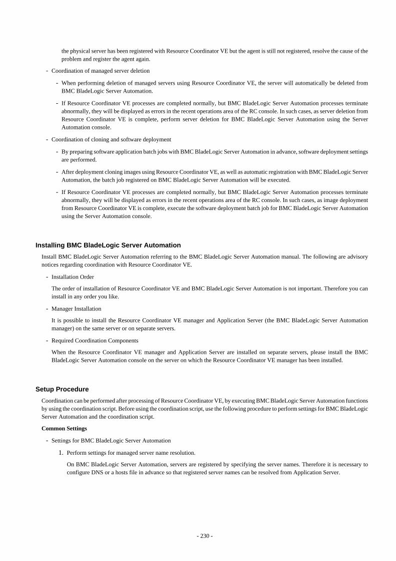
the physical server has been registered with Resource Coordinator VE but the agent is still not registered, resolve the cause of theproblem and register the agent again.
- Coordination of managed server deletion
- When performing deletion of managed servers using Resource Coordinator VE, the server will automatically be deleted fromBMC BladeLogic Server Automation.
- If Resource Coordinator VE processes are completed normally, but BMC BladeLogic Server Automation processes terminateabnormally, they will be displayed as errors in the recent operations area of the RC console. In such cases, as server deletion fromResource Coordinator VE is complete, perform server deletion for BMC BladeLogic Server Automation using the ServerAutomation console.
- Coordination of cloning and software deployment
- By preparing software application batch jobs with BMC BladeLogic Server Automation in advance, software deployment settingsare performed.
- After deployment cloning images using Resource Coordinator VE, as well as automatic registration with BMC BladeLogic ServerAutomation, the batch job registered on BMC BladeLogic Server Automation will be executed.
- If Resource Coordinator VE processes are completed normally, but BMC BladeLogic Server Automation processes terminateabnormally, they will be displayed as errors in the recent operations area of the RC console. In such cases, as image deploymentfrom Resource Coordinator VE is complete, execute the software deployment batch job for BMC BladeLogic Server Automationusing the Server Automation console.
Installing BMC BladeLogic Server Automation
Install BMC BladeLogic Server Automation referring to the BMC BladeLogic Server Automation manual. The following are advisorynotices regarding coordination with Resource Coordinator VE.
- Installation Order
The order of installation of Resource Coordinator VE and BMC BladeLogic Server Automation is not important. Therefore you caninstall in any order you like.
- Manager Installation
It is possible to install the Resource Coordinator VE manager and Application Server (the BMC BladeLogic Server Automationmanager) on the same server or on separate servers.
- Required Coordination Components
When the Resource Coordinator VE manager and Application Server are installed on separate servers, please install the BMCBladeLogic Server Automation console on the server on which the Resource Coordinator VE manager has been installed.
Setup Procedure
Coordination can be performed after processing of Resource Coordinator VE, by executing BMC BladeLogic Server Automation functionsby using the coordination script. Before using the coordination script, use the following procedure to perform settings for BMC BladeLogicServer Automation and the coordination script.
Common Settings
- Settings for BMC BladeLogic Server Automation
1. Perform settings for managed server name resolution.
On BMC BladeLogic Server Automation, servers are registered by specifying the server names. Therefore it is necessary toconfigure DNS or a hosts file in advance so that registered server names can be resolved from Application Server.
- 230 -
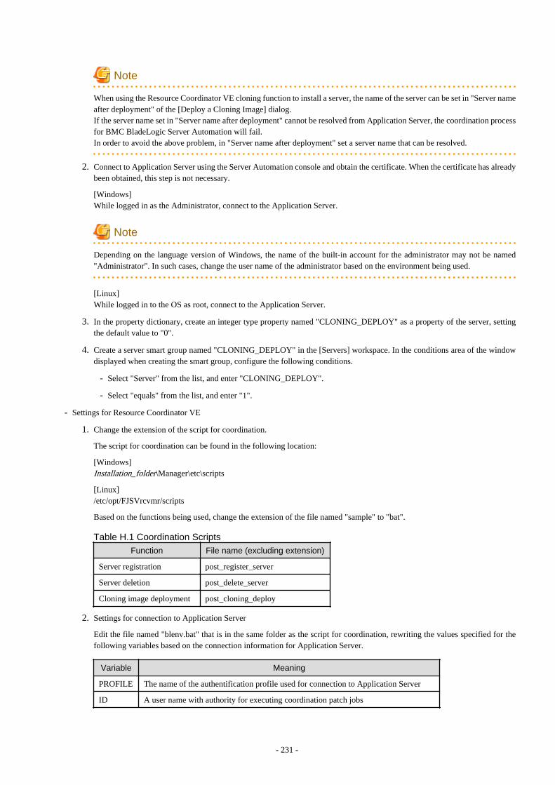
Note
When using the Resource Coordinator VE cloning function to install a server, the name of the server can be set in "Server nameafter deployment" of the [Deploy a Cloning Image] dialog.If the server name set in "Server name after deployment" cannot be resolved from Application Server, the coordination processfor BMC BladeLogic Server Automation will fail.In order to avoid the above problem, in "Server name after deployment" set a server name that can be resolved.
2. Connect to Application Server using the Server Automation console and obtain the certificate. When the certificate has alreadybeen obtained, this step is not necessary.
[Windows]While logged in as the Administrator, connect to the Application Server.
Note
Depending on the language version of Windows, the name of the built-in account for the administrator may not be named"Administrator". In such cases, change the user name of the administrator based on the environment being used.
[Linux]While logged in to the OS as root, connect to the Application Server.
3. In the property dictionary, create an integer type property named "CLONING_DEPLOY" as a property of the server, settingthe default value to "0".
4. Create a server smart group named "CLONING_DEPLOY" in the [Servers] workspace. In the conditions area of the windowdisplayed when creating the smart group, configure the following conditions.
- Select "Server" from the list, and enter "CLONING_DEPLOY".
- Select "equals" from the list, and enter "1".
- Settings for Resource Coordinator VE
1. Change the extension of the script for coordination.
The script for coordination can be found in the following location:
[Windows]Installation_folder\Manager\etc\scripts
[Linux]/etc/opt/FJSVrcvmr/scripts
Based on the functions being used, change the extension of the file named "sample" to "bat".
Table H.1 Coordination Scripts
Function File name (excluding extension)
Server registration post_register_server
Server deletion post_delete_server
Cloning image deployment post_cloning_deploy
2. Settings for connection to Application Server
Edit the file named "blenv.bat" that is in the same folder as the script for coordination, rewriting the values specified for thefollowing variables based on the connection information for Application Server.
Variable Meaning
PROFILE The name of the authentification profile used for connection to Application Server
ID A user name with authority for executing coordination patch jobs
- 231 -
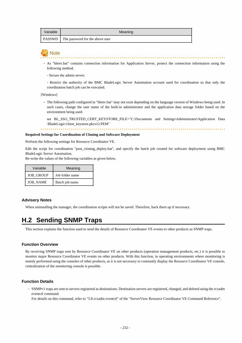
Variable Meaning
PASSWD The password for the above user
Note
- As "blenv.bat" contains connection information for Application Server, protect the connection information using thefollowing method.
- Secure the admin server.
- Restrict the authority of the BMC BladeLogic Server Automation account used for coordination so that only thecoordination batch job can be executed.
[Windows]
- The following path configured in "blenv.bat" may not exist depending on the language version of Windows being used. Insuch cases, change the user name of the built-in administrator and the application data storage folder based on theenvironment being used.
set BL_SSO_TRUSTED_CERT_KEYSTORE_FILE="C:\Documents and Settings\Administrator\Application Data\BladeLogic\client_keystore.pkcs12.PEM"
Required Settings for Coordination of Cloning and Software Deployment
Perform the following settings for Resource Coordinator VE.
Edit the script for coordination "post_cloning_deploy.bat", and specify the batch job created for software deployment using BMCBladeLogic Server Automation.Re-write the values of the following variables as given below.
Variable Meaning
JOB_GROUP Job folder name
JOB_NAME Batch job name
Advisory Notes
When uninstalling the manager, the coordination scripts will not be saved. Therefore, back them up if necessary.
H.2 Sending SNMP TrapsThis section explains the function used to send the details of Resource Coordinator VE events to other products as SNMP traps.
Function Overview
By receiving SNMP traps sent by Resource Coordinator VE on other products (operation management products, etc.) it is possible tomonitor major Resource Coordinator VE events on other products. With this function, in operating environments where monitoring ismainly performed using the consoles of other products, as it is not necessary to constantly display the Resource Coordinator VE console,centralization of the monitoring console is possible.
Function Details
- SNMPv1 traps are sent to servers registered as destinations. Destination servers are registered, changed, and deleted using the rcxadmeventctl command.For details on this command, refer to "5.8 rcxadm eventctl" of the "ServerView Resource Coordinator VE Command Reference".
- 232 -

- The SNMP traps sent by Resource Coordinator VE contain information about the operation details of Resource Coordinator VE. Forevents related to status changes of resources managed by Resource Coordinator VE and events internal to resources, the SNMP trapswill be sent by the resource itself.
- The events that are the target of sending as SNMP traps are as follow:
FJSVrcx:INFO:21143:operation:startedFJSVrcx:INFO:21144:operation:completedFJSVrcx:INFO:21145:operation:cancelledFJSVrcx:ERROR:61143:operation:failedFJSVrcx:ERROR:61144:operation:rollback failed
- For details of the Resource Coordinator VE events that are sent as SNMP traps, check the event log of the RC console.
Setup Procedure
This section explains the procedure for setting other products to receive Resource Coordinator VE SNMP traps.Here it is assumed that installation of other products for receiving SNMP traps has been performed, and that basic settings such as thoseof the SNMP trap service necessary to receive traps and the required ports, have been made.
1. Configure a SNMP community name for the product that will receive SNMP traps.Enter a string of up to 32 alphanumerical characters, hyphens ("-"), and underscores ("_") for the SNMP community name.
2. Load the Resource Coordinator VE MIB file on the product that is to receive SNMP traps.The MIB file that defines the SNMP traps for Resource Coordinator VE is located in the following folder on the admin server.
[Windows]Installation_folder\Manager\etc\mibs\RCVE-Event-Trap-MIB.mib
[Linux]/etc/opt/FJSVrcvmr/mibs/RCVE-Event-Trap-MIB.mib
3. Register destination servers using the rcxadm eventctl add command of Resource Coordinator VE.
Modification procedure
Use the following procedure to change SNMP trap destination settings:
1. Delete the target destination server information using the rcxadm eventctl delete command of Resource Coordinator VE.
2. Register the new destination servers using the rcxadm eventctl add command of Resource Coordinator VE.
Deletion procedure
Delete the target destination server information using the rcxadm eventctl delete command of Resource Coordinator VE.
Operation Checks
Use the following procedure to confirm that SNMP trap destinations have been registered correctly.
1. From the RC console, place the desired managed server into maintenance mode.
a. In the RC console server resource tree, right-click the desired server (or its physical OS), and select [Maintenance Mode]-[Set] from the popup menu.
The [Set Maintenance Mode] dialog is displayed.
b. Click <OK>.
- 233 -

2. The managed server is released from maintenance mode.
a. In the RC console server resource tree, right-click the desired server (or its physical OS) and select [Maintenance Mode]-[Release] from the popup menu.
The [Release Maintenance Mode] dialog is displayed.
b. Click <OK>.
As a result of the above operation, the following 4 events will be sent as SNMP traps to the registered server. If the destination has beenregistered correctly, it is possible to check the receipt of the Resource Coordinator VE SNMP traps on the destination device.Please note that the display of SNMP traps varies depending on the product.
Event ID OID
FJSVrcx:INFO:21143: setting maintenance mode:started 1.3.6.1.4.1.211.4.1.3.55.100.1.2.1.21143
FJSVrcx:INFO:21144: setting maintenance mode:completed 1.3.6.1.4.1.211.4.1.3.55.100.1.2.1.21144
FJSVrcx:INFO:21143: releasing maintenance mode:started 1.3.6.1.4.1.211.4.1.3.55.100.1.2.1.21143
FJSVrcx:INFO:21144: releasing maintenance mode:completed 1.3.6.1.4.1.211.4.1.3.55.100.1.2.1.21144
If the receipt of SNMP traps cannot be confirmed, use the rcxadm eventctl command to check if the desired destination has been registeredcorrectly. If there are no problems with the registered details, check that there are no problems with the network or the settings for theSNMP trap destination. After resolving any problems, repeat the above procedure and check if the Resource Coordinator VE SNMP trapscan be received.
H.2.1 SNMP Trap Settings Using CA SpectrumThis section explains the settings for CA Spectrum to receive Resource Coordinator VE SNMP traps.Also refer to "H.2 Sending SNMP Traps".
For details on CA Spectrum, refer to the CA Spectrum manual.
External Software
The information in this manual has been based on that of CA Spectrum Infrastructure Manager r9.1.2.Depending on the version of CA Spectrum Infrastructure Manager, some of the terms and procedures may differ slightly from those givenhere.
Installing CA Spectrum
Perform installation of CA Spectrum referring to the CA Spectrum manual.The following are advisory notices regarding coordination with Resource Coordinator VE.
- Installation Order
The order of installation of Resource Coordinator VE and CA Spectrum is not important. Therefore you can install in any order youlike.
- Manager Installation
[Windows]The Resource Coordinator VE manager and CA Spectrum's manager, SpectroSERVER cannot be installed on the same server.Install the Resource Coordinator VE manager and the CA Spectrum manager on separate servers.
[Linux]The Resource Coordinator VE manager and CA Spectrum's manager, SpectroSERVER can be installed on the same server or onseparate servers. However, when they are installed on the same server, it is necessary to perform the settings given in "Preparations".
- 234 -

Preparations
Register the admin server on which the Resource Coordinator VE manager has been installed as a management target of CA spectrum.
[Linux]When installing the Resource Coordinator VE manager and SpectroSERVER on the same server, in order to share SNMP traps betweenResource Coordinator VE and CA Spectrum, ServerView Trap Server for Linux (trpsrvd) is necessary.ServerView Trap Server for Linux is a program which is used to transfer SNMP traps received at UDP port 162 to other UDP port numbers.
ServerView Trap Server for Linux is shipped with some versions of ServerView Operations Manager. In such cases, install ServerViewTrap Server for Linux following the instructions given in the ServerView Operations Manager manual.
If ServerView Trap Server for Linux is not shipped with ServerView Operations Manager, download it from the following site, and installit referring to the attached documents.
URL: http://download.ts.fujitsu.com/prim_supportcd/SVSSoftware/html/ServerView_e.html (As of August 2011)
Perform the following settings after installing ServerView Trap Server for Linux.
1. Log in as OS administrator (root).
2. Change the SpectroSERVER SNMP trap reception port to one other than 162.
The port number can be changed by editing the file shown below.
{SpectroSERVER_installation_folder}/CC/.vnmrc
Example
When changing the port number to 9162:
snmp_trap_port=9162
3. Restart SpectroSERVER.
4. Edit the /usr/share/SMAWtrpsv/conf/trpsrvtargets file and add the SpectroSERVER SNMP trap reception port.
Before editing
######################################################################### Copyright (C) Fujitsu Siemens Computers 2007# All rights reserved# Configuration File for trpsrv (SMAWtrpsv)######################################################################### Syntax# port [(address | -) [comment]]
# examples# 8162# 9162 - test# 162 145.25.124.121
After editing (When making the SpectroSERVER SNMP trap reception port 9162)
######################################################################### Copyright (C) Fujitsu Siemens Computers 2007# All rights reserved# Configuration File for trpsrv (SMAWtrpsv)########################################################################
# Syntax# port [(address | -) [comment]]
- 235 -

# examples# 8162# 9162 - test# 162 145.25.124.121
#Transfer to UDP port 9162.9162
5. Restart the system.
Setup Procedure
In this section the procedures for checking SNMP traps that CA spectrum receives from Resource Coordinator VE, as event messages onOneClick (CA Spectrum's console) are explained.Refer to the CA Spectrum manual for details on each procedure.
1. Start CA Spectrum's MIB Tools.
2. Click <Add MIB> on the "Navigation" panel.
The [MIB Tools: Add MIB] dialog is displayed.
3. Click <Browse> and select the Resource Coordinator VE MIB file.
4. Click <Compile>.
Confirm that compiling of the MIB file was successful in the messages displayed in "Compiler" of the [MIB Tools: Add MIB]dialog.
5. Click <Add & Close>.
The loaded MIB is displayed in the MIB Tools "Navigation" panel.
6. On "Navigation" panel, select the Resource Coordinator VE MIB, and click the [Map] tab on the "Contents" panel.
7. Select the trap displayed in "Trap Support", and click <Information> to check the trap details.
8. Select the trap displayed in "Trap Support", and click <Map Traps>.
The [MIB Tools: Assign Trap Alarms] dialog is displayed.
9. Click <set> in "Alarm Severity", and select the severity of alarms for each trap.
10. Click <OK>.
The [MIB Tools: Trap Support Results] dialog will be displayed, and you can check the results of the operation.
11. Click <Close>.
Check that event codes have been allocated for each trap in the MIB Tools "Trap Support".
12. Select a trap from "Trap Support", and click <Edit Traps>.
The Event Configuration application will start.
13. On the "Navigation" panel, select the event code allocated to the trap.
14. In "Event Message" of the "Contents" panel, the event message to be displayed when the trap is received is displayed.
The message can be edited following the format specified by CA Spectrum.For details of the format, refer to the CA Spectrum manual.
15. After changing a message, select [Save All] or [Save Selected] from the Event Configuration application menu and save the settings.
After performing the above settings, perform the operation check described in "H.2 Sending SNMP Traps".
H.3 Single Sign-OnThis section explains the function to perform Single Sign-On for ServerView Operations Manager, which is external software.
- 236 -

External Software
Resource Coordinator VE can be coordinated with ServerView Operations Manager V5.0 or later and Single Sign-On.
Function Overview
Through coordination, the following becomes possible:
- When logged in to ServerView Operations Manager using Single Sign-On
Login to Resource Coordinator VE is possible, without entering the user name and password.
- When logged in to Resource Coordinator VE using Single Sign-On
Login to ServerView Operations Manager is possible without entering the user name and password.
Note
- Resource Coordinator VE and ServerView Operations Manager must be installed on the same server.
- It is necessary to configure Single Sign-On on ServerView Operations Manager in advance.
- It is not possible to use this function when executing cluster operations.
H.3.1 Defining the LDAP Server EnvironmentDecide the operational environment in which to performance Single Sign-On.
- Environments using the OpenDS enclosed with ServerView Operations Manager
- Environments where individually configured directory service are used
- Use OpenDS
- Use Active Directory
H.3.2 ConfigurationCoordination can be performed by registering the directory service with Resource Coordinator VE.By deleting the registered directory service, the coordination can be released. Use the following procedure to configure the directoryservice.
Configuring LDAP Servers
Use the following procedure to perform LDAP server configuration.
- Import LDIF files
Use the following procedure to import LDIF files.
When using OpenDS (Enclosed with ServerView Operations Manager, individual configuration)
When performing individual configuration, the base name (dc=fujitsu,dc=com) of the actual environment may be different from onedescribed in the LDIF file. Check the base name of the directory service being used, and if the relevant base name is not correct,change it using an editor.
- Use the following LDIF files.
[Windows]Installation_folder\Manager\etc\conf\ssoconf\rcve_opends.ldif
[Linux]/etc/opt/FJSVrcvmr/conf/ssoconf/rcve_opends.ldif
- 237 -

- Execute the following commands, and import the LDIF files.
[Windows]
>"OpenDS_installation_folder\bat\ldapmodify.bat" -p Port_number -f LDIF_file -DAdministrator_user_DN -w Password <RETURN>
[Linux]
>"OpenDS_installation_folder/bin/ldapmodify" -p Port_number -f LDIF_file -DAdministrator_user_DN -w Password <RETURN>
Example
>"C:\Program Files\Fujitsu\ServerView Suite\opends\bat\ldapmodify.bat" -p 1473 -f "C:\Documents andSettings\tamura\My Documents\download\ldap\rcve_opends.ldif" -D "cn=Directory Manager" -w adminProcessing ADD request for OU=RCVE,OU=Privileges,OU=Declarations,OU=SVS,dc=fujitsu,dc=com...
ADD operation successful forcn=Administrator,OU=AuthorizationRoles,OU=RCVE,OU=Departments,OU=SVS,dc=fujitsu,dc=com
Note
Depending on the environment, a JAVA execution error may be displayed.If a JAVA execution error is displayed, check that the correct JAVA execution path is set in the environment variables.
Configuration when using Active Directory (individual configuration)
- Use the following LDIF files.
The base name (dc=fujitsu,dc=com) of the actual environment may be different from the one described in the LDIF file. Checkthe base name of the directory service being used, and if the relevant base name is not correct, change it using an editor.
When using Linux, copy the LDIF file from a Windows environment where there are Active Directories.
[Windows]Installation_folder\Manager\etc\conf\ssoconf\rcve_active_directory.ldif
[Linux]/etc/opt/FJSVrcvmr/conf/ssoconf/rcve_active_directory.ldif
- Execute the following commands, and import the LDIF files.
[Windows]
>ldifde -i -e -k -f LDIF_file <RETURN>
Information
When the ldifde tool is not included in the PATH variable, it is in the %WINDIR%\system32 directory.
- Configuration of User Authority Levels
Configure the authority levels of the users registered in the directory service. Add the users as members using the following roles.
- 238 -

Table H.2 User Authority LevelsAuthority Name Authority Level LDAP Server Role Name
RcveManageAdministrative user ofResource Coordinator VE
cn=Administrator,OU=AuthorizationRoles,OU=RCVE,OU=Departments,OU=SVS,BaseDN
RcveMonitorGeneral user of ResourceCoordinator VE
cn=Monitor,OU=AuthorizationRoles,OU=RCVE,OU=Departments,OU=SVS,BaseDN
For details, follow the configuration methods for the directory service being used.
Manager Configuration
Use the following procedure to configure managers. Perform configuration after stopping manager services.Start the manager services again after configuration is complete.For information on starting and stopping managers, refer to the "5.1 Manager" section.
- Directory Service Registration
Register the directory service used for ServerView Operations Manager with Resource Coordinator VE.Use the following procedure to register the directory service.
1. Execute the following commands to register the directory service.
[Windows]
>"Installation_folder\Manager\bin\rcxadm" authctl register -ip IP_address -port Port_number -baseBaseDN -bind Administrator_user_DN -method SSL -passwd Password <RETURN>
[Linux]
#/opt/FJSVrcvmr/bin/rcxadm authctl register -ip IP_address -port Port_number -base BaseDN -bindAdministrator_user_DN -method SSL -passwd Password <RETURN>
2. Execute the following commands to check the details of configuration.
[Windows]
>"Installation_folder\Manager\bin\rcxadm" authctl show <RETURN>
[Linux]
#/opt/FJSVrcvmr/bin/rcxadm authctl show <RETURN>
Example
>"C:\Program Files\Resource Coordinator VE\Manager\bin\rcxadm" authctl register -ip 192.168.1.10-port 1474 -base dc=fujitsu,dc=com -bind "cn=Directory Manager" -method SSL -passwd admin
>"C:\Program Files\Resource Coordinator VE\Manager\bin\rcxadm" authctl showip address: 192.168.1.10port: 1474base: dc=fujitsu,dc=combind: cn=Directory Managermethod: SSL
- Import the LDAPS Certificate
Common Settings
- 239 -
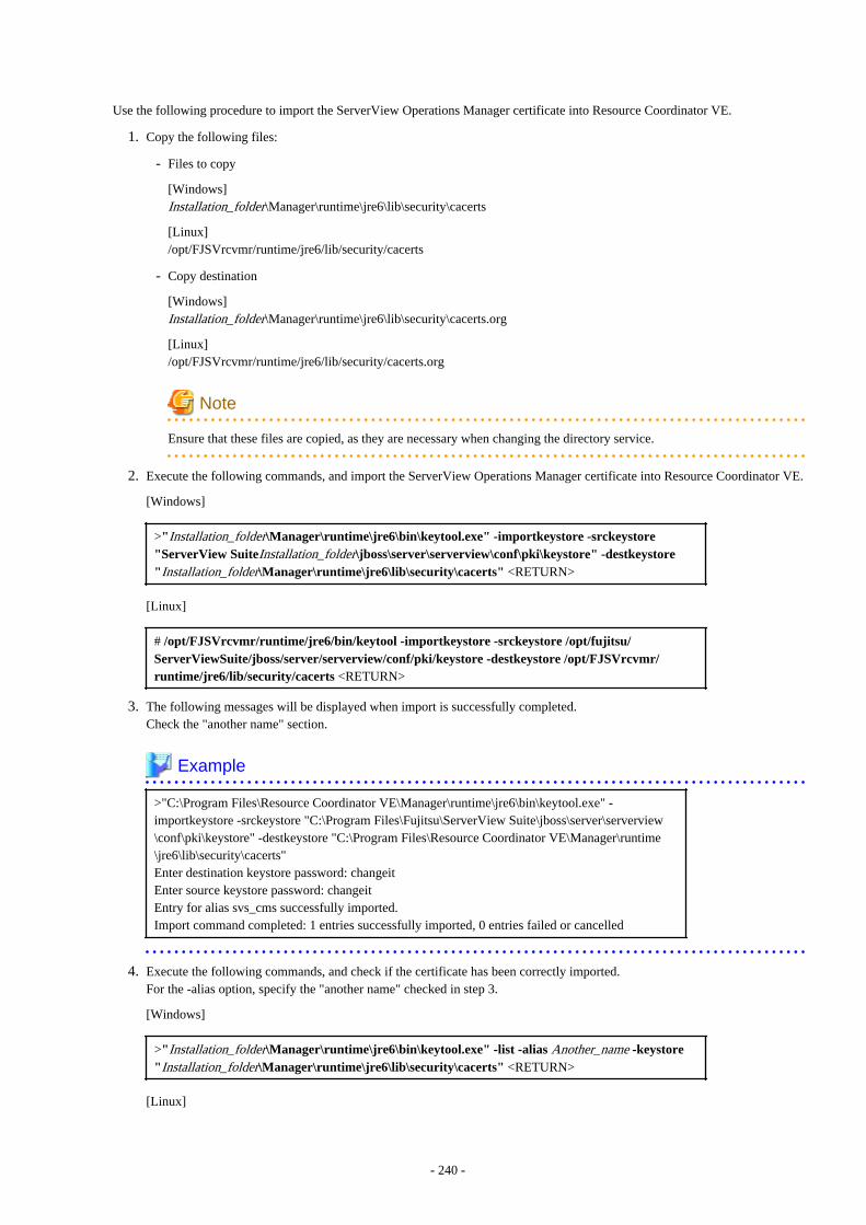
Use the following procedure to import the ServerView Operations Manager certificate into Resource Coordinator VE.
1. Copy the following files:
- Files to copy
[Windows]Installation_folder\Manager\runtime\jre6\lib\security\cacerts
[Linux]/opt/FJSVrcvmr/runtime/jre6/lib/security/cacerts
- Copy destination
[Windows]Installation_folder\Manager\runtime\jre6\lib\security\cacerts.org
[Linux]/opt/FJSVrcvmr/runtime/jre6/lib/security/cacerts.org
Note
Ensure that these files are copied, as they are necessary when changing the directory service.
2. Execute the following commands, and import the ServerView Operations Manager certificate into Resource Coordinator VE.
[Windows]
>"Installation_folder\Manager\runtime\jre6\bin\keytool.exe" -importkeystore -srckeystore"ServerView SuiteInstallation_folder\jboss\server\serverview\conf\pki\keystore" -destkeystore"Installation_folder\Manager\runtime\jre6\lib\security\cacerts" <RETURN>
[Linux]
# /opt/FJSVrcvmr/runtime/jre6/bin/keytool -importkeystore -srckeystore /opt/fujitsu/ServerViewSuite/jboss/server/serverview/conf/pki/keystore -destkeystore /opt/FJSVrcvmr/runtime/jre6/lib/security/cacerts <RETURN>
3. The following messages will be displayed when import is successfully completed.Check the "another name" section.
Example
>"C:\Program Files\Resource Coordinator VE\Manager\runtime\jre6\bin\keytool.exe" -importkeystore -srckeystore "C:\Program Files\Fujitsu\ServerView Suite\jboss\server\serverview\conf\pki\keystore" -destkeystore "C:\Program Files\Resource Coordinator VE\Manager\runtime\jre6\lib\security\cacerts"Enter destination keystore password: changeitEnter source keystore password: changeitEntry for alias svs_cms successfully imported.Import command completed: 1 entries successfully imported, 0 entries failed or cancelled
4. Execute the following commands, and check if the certificate has been correctly imported.For the -alias option, specify the "another name" checked in step 3.
[Windows]
>"Installation_folder\Manager\runtime\jre6\bin\keytool.exe" -list -alias Another_name -keystore"Installation_folder\Manager\runtime\jre6\lib\security\cacerts" <RETURN>
[Linux]
- 240 -

# /opt/FJSVrcvmr/runtime/jre6/bin/keytool -list -alias Another_name -keystore /opt/FJSVrcvmr/runtime/jre6/lib/security/cacerts <RETURN>
5. The message will be displayed, when the certificate confirmation is successfully completed.
Example
>"C:\Program Files\Resource Coordinator VE\Manager\runtime\jre6\bin\keytool.exe" -list -aliassvs_cms -keystore "Installation_folder\Manager\runtime\jre6\lib\security\cacerts"Enter keystore password: changeitsvs_cms, 2010/10/05, PrivateKeyEntry,Certificate fingerprints (MD5): C9:3C:8B:8B:C6:BA:67:92:89:70:D1:00:55:A3:CD:6
Individual Configuration
- When using the configured OpenDS individually.
When using an individually configured OpenDS, it is necessary to import the configured OpenDS server certificate.
Use the following procedure to import the server certificate of the individually configured OpenDS.The server certificate format is the JKS(Java Key Store) format.
1. Execute the following commands, and import the OpenDS server certificate into Resource Coordinator VE.
[Windows]
>"Installation_folder\Manager\runtime\jre6\bin\keytool.exe" -importkeystore -srckeystore"OpenDSInstallation_folder\config\keystore" -destkeystore "Installation_folder\Manager\runtime\jre6\lib\security\cacerts" <RETURN>
[Linux]
# /opt/FJSVrcvmr/runtime/jre6/bin/keytool -importkeystore -srckeystore"OpenDSInstallation_folder/config/keystore" -destkeystore /opt/FJSVrcvmr/runtime/jre6/lib/security/cacerts <RETURN>
2. The following messages will be displayed when import is successfully completed.Check the "another name" section.
Example
>"C:\Program Files\Resource Coordinator VE\Manager\runtime\jre6\bin\keytool.exe" -importkeystore -srckeystore "C:\win32app\OpenDS-2.2.0\config\keystore" -destkeystore "C:\Program Files\Resource Coordinator VE\Manager\runtime\jre6\lib\security\cacerts"Enter destination keystore password: changeitEnter source keystore password: changeitEntry for alias server-cert successfully imported.Import command completed: 1 entries successfully imported, 0 entries failed or cancelled
3. Execute the following commands, and check if the certificate has been correctly imported.For the -alias option, specify the "another name" checked in step 2.
[Windows]
>"Installation_folder\Manager\runtime\jre6\bin\keytool.exe" -list -alias Another_name -keystore "Installation_folder\Manager\runtime\jre6\lib\security\cacerts" <RETURN>
[Linux]
- 241 -

># /opt/FJSVrcvmr/runtime/jre6/bin/keytool -list -alias Another_name -keystore /opt/FJSVrcvmr/runtime/jre6/lib/security/cacerts <RETURN>
4. The message will be displayed, when the certificate confirmation is successfully completed.
Example
>"C:\Program Files\Resource Coordinator VE\Manager\runtime\jre6\bin\keytool.exe" -list -alias server -cert -keystore "Installation_folder\Manager\runtime\jre6\lib\security\cacerts"Enter keystore password: changeitserver -cert, 2010/10/05, PrivateKeyEntry,Certificate fingerprints (MD5): 15:6F:61:8E:54:E3:57:99:8C:24:A5:76:1A:D4:4D:E0
- Configuration when using Active Directory
When using Active Directory, it is necessary to import the Active Directory server certificate.
Use the following procedure to import Active Directory server certificates.The server certificate format is the DER encoded binary X.509(CER) format.
1. Execute the following commands, and import Active Directory certificates into Resource Coordinator VE.For the -alias option, specify "rcve_ldap".
[Windows]
>"Installation_folder\Manager\runtime\jre6\bin\keytool.exe" -importcert -alias rcve_ldap -trustcacerts -file Certificate_path -keystore "Installation_folder\Manager\runtime\jre6\lib\security\cacerts" <RETURN>
[Linux]
# /opt/FJSVrcvmr/runtime/jre6/bin/keytool -importcert -alias rcve_ldap -trustcacerts -fileCertificate_path -keystore /opt/FJSVrcvmr/runtime/jre6/lib/security/cacerts <RETURN>
2. The following confirmation message is displayed:When the certificate is trusted, to add it to a key store, enter "yes", to cancel the addition, enter "no".
Do you trust this certificate? [no]:
Example
>"C:\Program Files\Resource Coordinator VE\Manager\runtime\jre6\bin\keytool.exe" -importcert -aliasrcve_ldap -trustcacerts -file c:\1472-VM13-w23r2.serverview.local_svsca.crt -keystore "C:\Program Files\Resource Coordinator VE\Manager\runtime\jre6\lib\security\cacerts"
Enter keystore password: changeit
Owner: CN=svsca, DC=serverview, DC=local
Issuer: CN=svsca, DC=serverview, DC=local
Serial number: 22646549ec7ac1994cc3a2b8eff66e27
Valid from: Mon Oct 04 11:19:47 JST 2010 until: Sun Oct 04 11:26:54 JST 2015
Certificate fingerprints:
MD5: 70:E3:CB:23:6F:D1:17:00:56:CA:E2:0D:30:73:14:A8
SHA1: 01:3C:06:81:2D:3F:6D:D9:C3:A6:D4:AA:7B:D5:5E:D5:5F:43:90:E5
Signature algorithm name: SHA1withRSA
Version: 3
...
Trust this certificate? [no]: yes
- 242 -

3. The following messages will be displayed, when addition to a key store is successfully completed.
The certificate is added to the key store.
4. Execute the following commands, and check if the certificate has been correctly imported.For the -alias option, specify "rcve_ldap".
[Windows]
>"Installation_folder\Manager\runtime\jre6\bin\keytool.exe" -list -alias rcve_ldap -keystore"Installation_folder\Manager\runtime\jre6\lib\security\cacerts" <RETURN>
[Linux]
# /opt/FJSVrcvmr/runtime/jre6/bin/keytool -list -alias rcve_ldap -keystore /opt/FJSVrcvmr/runtime/jre6/lib/security/cacerts <RETURN>
5. The message will be displayed, when the certificate confirmation is successfully completed.
Example
>"C:\Program Files\Resource Coordinator VE\Manager\runtime\jre6\bin\keytool.exe" -list -alias rcve_ldap -keystore "Installation_folder\Manager\runtime\jre6\lib\security\cacerts"Enter keystore password: changeitrcve_ldap, 2010/10/05, trustedCertEntry,Certificate fingerprints (MD5): 70:E3:CB:23:6F:D1:17:00:56:CA:E2:0D:30:73:14:A8
Information
"changeit" is configured as the default password for key stores.
H.3.3 Modifying SettingsThis section explains how to change the settings for directory services.Use the following procedure to change directory services.
1. Restore the following files copied in "Import LDIF files" as described in "H.3.2 Configuration".
- Files to copy
[Windows]Installation_folder\Manager\runtime\jre6\lib\security\cacerts.org
[Linux]/opt/FJSVrcvmr/runtime/jre6/lib/security/cacerts.org
- Copy destination
[Windows]Installation_folder\Manager\runtime\jre6\lib\security\cacerts
[Linux]/opt/FJSVrcvmr/runtime/jre6/lib/security/cacerts
2. Re-configure according to the configuration procedure in the "H.3.2 Configuration".However, execute the following commands in step 1. of "Directory Service Registration".
[Windows]
>"Installation_folder\Manager\bin\rcxadm" authctl modify {[-ip IP_address] [-port Port_number] [-baseBaseDN] [-bind Administrator_user_DN -passwd Password] [-method SSL]} <RETURN>
- 243 -

[Linux]
#/opt/FJSVrcvmr/bin/rcxadm authctl modify {[-ip IP_address] [-port Port_number] [-base BaseDN] [-bindAdministrator_user_DN -passwd Password] [-method SSL]} <RETURN>
- 244 -

Appendix I WWN Allocation Order During HBA addressrename Configuration
This section explains the order in which WWNs are allocated during configuration of HBA address rename.
With HBA address rename, as WWNs are allocated to the I/O addresses of HBAs in descending order, the order may not match the portorder listed in the HBA.When specifying the locations for WWN allocation, check the I/O addresses of HBAs.The I/O addresses of HBAs can be confirmed using tools provided by HBA vendors or FC-HBA BIOS.
- For blade servers
Example
For a blade server with an HBA with 2 ports, allocation is performed as follows:
WWN value provided by "I/O Virtualization Option": 20:00:00:17:42:51:00:00
WWNN value for ports 1 and 2 of the HBA : 20:00:00:17:42:51:00:00
WWPN value for HBA port 1 : 9:00:00 PM:17:42:51:00:00
WWPN value for HBA port 2 : 10:00:00 PM:17:42:51:00:00
- For rack mount or tower servers
For the PCI slots of rack mount or tower servers, WWNs are allocated in the following order:
PRIMERGY RX200 S4 slot2 -> slot1 -> slot3
PRIMERGY RX200 S5 slot1 -> slot2 -> slot3
PRIMERGY RX300 S4 slot5 -> slot6 -> slot1 -> slot7 -> slot4 -> slot2 -> slot3
PRIMERGY RX300 S5 slot2 -> slot3 -> slot4 -> slot5 -> slot6 -> slot7 -> slot1
PRIMERGY RX600 S4 slot6 -> slot3 -> slot4 -> slot1 -> slot2 -> slot7 -> slot5
PRIMERGY TX300 S4 slot5 -> slot6 -> slot1 -> slot7 -> slot4 -> slot2 -> slot3
In a single PCI slot, allocate WWNs in the following order:
port 2 -> port 1
Example
When 1 port HBAs are mounted in slot 2 and slot 3 of an RX600 S4, WWNs are allocated in the following order:
slot 3 -> slot 2
WWN value provided by "I/O Virtualization Option": 20:00:00:17:42:51:00:00
WWNN value for slots 2 and 3 of the HBA : 20:00:00:17:42:51:00:00
WWPN value for HBA slot 2 : 22:00:00:17:42:51:00:00
WWPN value for HBA slot 3 : 21:00:00:17:42:51:00:00
When 2 port HBAs are mounted in slot 2 of an RX600 S4, WWNs are allocated in the following order:
slot 2 (port 2) -> slot 2 (port 1)
WWN value provided by "I/O Virtualization Option": 20:00:00:17:42:51:00:00
WWNN value for ports 1 and 2 of the HBA : 20:00:00:17:42:51:00:00
WWPN value for HBA port 1 : 10:00:00 PM:17:42:51:00:00
WWPN value for HBA port 2 : 9:00:00 PM:17:42:51:00:00
- 245 -

Appendix J Co-Existence with ServerView DeploymentManager
This appendix explains how to use both Resource Coordinator VE and ServerView Deployment Manager on the same network.
J.1 OverviewResource Coordinator VE and ServerView Deployment Manager can be installed either on the same server or on two different servers. Inboth cases, they can share the same subnet (admin LAN) to control managed servers. In a shared subnet configuration, ServerViewDeployment Manager should be used instead of Resource Coordinator VE for all image operations such as server cloning, backup andrestore.
Figure J.1 System Configuration Example (Separate Server Installation)
- 246 -

Figure J.2 System Configuration Example (Single Server Installation)
J.2 Restricted FunctionsIn such a shared subnet configuration, the following functions are no longer available from Resource Coordinator VE.
- Backup and restore
- Cloning
- I/O virtualization (HBA address rename)
- Server switchover (based on the backup-restore and HBA address rename methods)
However, server switchover based on the VIOM method is still available in Resource Coordinator VE.
Instead, it is recommended to use the following ServerView products.
- ServerView Deployment Manager (for cloning, backup and restore)
- ServerView Virtual-IO Manager (for I/O virtualization)
- 247 -

Glossary access path
A logical path configured to enable access to storage volumes from servers.
active mode
The state where a managed server is performing operations.Managed servers must be in active mode in order to use Auto-Recovery.Move managed servers to maintenance mode in order to perform backup or restoration of system images, or collection or deploymentof cloning images.
active server
A physical server that is currently operating.
admin client
A terminal (PC) connected to an admin server, which is used to operate the GUI.
admin LAN
A LAN used to manage resources from admin servers.It connects managed servers, storage and networks devices.
admin server
A server used to operate the manager software of Resource Coordinator VE.
affinity group
A grouping of the storage volumes allocated to servers. A function of ETERNUS.
Equivalent to the LUN mapping of EMC.
agent
The section (program) of Resource Coordinator VE that operates on managed servers.
Auto-Recovery
A function which continues operations by automatically switching over the system image of a failed server to a spare server andrestarting it in the event of server failure.This function can be used when managed servers are in a local boot configuration, SAN boot configuration, or a configuration suchas iSCSI boot where booting is performed from a disk on a network.When using a local boot configuration, the system is recovered by restoring a backup of the system image of the failed server onto aspare server.In configurations using SAN boot or booting from a disk on a LAN, the system is recovered by a spare server inheriting the systemimage of the failed server over the storage network.Also, when a VLAN is set for the public LAN of a managed server, the VLAN settings of adjacent LAN switches are automaticallyswitched to those of the spare server.
BACS (Broadcom Advanced Control Suite)
An integrated GUI application (comprised from applications such as BASP) that creates teams from multiple NICs, and providesfunctions such as load balancing.
BASP (Broadcom Advanced Server Program)
LAN redundancy software that creates teams of multiple NICs, and provides functions such as load balancing and failover.
- 248 -

blade server
A compact server device with a thin chassis that can contain multiple server blades, and has low power consumption.As well as server blades, LAN switch blades, management blades, and other components used by multiple server blades can be mountedinside the chassis.
blade type
A server blade type.Used to distinguish the number of server slots used and servers located in different positions.
BladeViewer
A GUI that displays the status of blade servers in a style similar to a physical view and enables intuitive operation.BladeViewer can also be used for state monitoring and operation of resources.
BMC (Baseboard Management Controller)
A Remote Management Controller used for remote operation of servers.
boot agent
An OS for disk access that is distributed from the manager to managed servers in order to boot them when the network is started duringimage operations.
CA (Channel Adapter)
An adapter card that is used as the interface for server HBAs and fibre channel switches, and is mounted on storage devices.
chassis
A chassis used to house server blades and partitions.Sometimes referred to as an enclosure.
cloning
Creation of a copy of a system disk.
cloning image
A backup of a system disk, which does not contain server-specific information (system node name, IP address, etc.), made duringcloning.When deploying a cloning image to the system disk of another server, Resource Coordinator VE automatically changes server-specificinformation to that of the target server.
Domain
A system that is divided into individual systems using partitioning. Also used to indicate a partition.
environmental data
Measured data regarding the external environments of servers managed using Resource Coordinator VE.Measured data includes power data collected from power monitoring targets.
ESC (ETERNUS SF Storage Cruiser)
Software that supports stable operation of multi-vendor storage system environments involving SAN, DAS, or NAS. Providesconfiguration management, relation management, trouble management, and performance management functions to integrate storagerelated resources such as ETERNUS.
FC switch (Fibre Channel Switch)
A switch that connects Fibre Channel interfaces and storage devices.
- 249 -

fibre channel switch blade
A fibre channel switch mounted in the chassis of a blade server.
GLS (Global Link Services)
Fujitsu network control software that enables high-availability networks through the redundancy of network transmission channels.
GSPB (Giga-LAN SAS and PCI_Box Interface Board)
A board which mounts onboard I/O for two partitions and a PCIe (PCI Express) interface for a PCI box.
GUI (Graphical User Interface)
A user interface that displays pictures and icons (pictographic characters), enabling intuitive and easily understandable operation.
HA (High Availability)
The concept of using redundant resources to prevent suspension of system operations due to single problems.
hardware initiator
A controller which issues SCSI commands to request processes.In iSCSI configurations, NICs fit into this category.
hardware maintenance mode
In maintenance mode of PRIMERGY Partition Model servers, a state other than Hot System Maintenance.
HBA (Host Bus Adapter)
An adapter for connecting servers and peripheral devices.Mainly used to refer to the FC HBAs used for connecting storage devices using Fibre Channel technology.
HBA address rename setup service
The service that starts managed servers that use HBA address rename in the event of failure of the admin server.
HBAAR (HBA address rename)
I/O virtualization technology that enables changing of the actual WWN possessed by an HBA.
host affinity
A definition of the server HBA that is set for the CA port of the storage device and the accessible area of storage.It is a function for association of the Logical Volume inside the storage which is shown to the host (HBA), that also functions as securityinternal to the storage device.
Hyper-V
Virtualization software from Microsoft Corporation.
Provides a virtualized infrastructure on PC servers, enabling flexible management of operations.
IBP (Intelligent Blade Panel)
One of operation modes used for PRIMERGY switch blades.This operation mode can be used for coordination with ServerView Virtual I/O Manager(VIOM), and relations between server bladesand switch blades can be easily and safely configured.
ILOM (Integrated Lights Out Manager)
The name of the Remote Management Controller for SPARC Enterprise T series servers.
- 250 -
image file
A system image or a cloning image. Also a collective term for them both.
I/O virtualization option
An optional product that is necessary to provide I/O virtualization.The WWNN address and MAC address provided is guaranteed by Fujitsu Limited to be unique.Necessary when using HBA address rename.
IPMI (Intelligent Platform Management Interface)
IPMI is a set of common interfaces for the hardware that is used to monitor the physical conditions of servers, such as temperature,power voltage, cooling fans, power supply, and chassis.These functions provide information that enables system management, recovery, and asset management, which in turn leads to reductionof overall TCO.
IQN (iSCSI Qualified Name)
Unique names used for identifying iSCSI initiators and iSCSI targets.
iRMC (integrated Remote Management Controller)
The name of the Remote Management Controller for Fujitsu's PRIMERGY servers.
iSCSI
A standard for using the SCSI protocol over TCP/IP networks.
LAN switch blade
A LAN switch that is mounted in the chassis of a blade server.
link aggregation
Function used to multiplex multiple ports and use them as a single virtual port.With this function, if one of the multiplexed ports fails its load can be divided among the other ports, and the overall redundancy ofports improved.
logical volume
A logical disk that has been divided into multiple partitions.
LSB (Logical System Board)
A system board that is allocated a logical number (LSB number) so that it can be recognized from the domain, during domainconfiguration.
maintenance mode
The state where operations on managed servers are stopped in order to perform maintenance work.In this state, the backup and restoration of system images and the collection and deployment of cloning images can be performed.However, when using Auto-Recovery it is necessary to change from this mode to active mode. When in maintenance mode it is notpossible to switch over to a spare server if a server fails.
managed server
A collective term referring to a server that is managed as a component of a system.
management blade
A server management unit that has a dedicated CPU and LAN interface, and manages blade servers.Used for gathering server blade data, failure notification, power control, etc.
- 251 -

Management Board
The PRIMERGY Partition Model system management unit.Used for gathering information such as failure notification, power control, etc. from chassis.
manager
The section (program) of Resource Coordinator VE that operates on admin servers.It manages and controls resources registered with Resource Coordinator VE.
master slot
A slot that is recognized as a server when a server that occupies multiple slots is mounted.
multi-slot server
A server that occupies multiple slots.
NAS (Network Attached Storage)
A collective term for storage that is directly connected to a LAN.
network map
A GUI function for graphically displaying the connection relationships of the servers and LAN switches that compose a network.
network view
A window that displays the connection relationships and status of the wiring of a network map.
NFS (Network File System)
A system that enables the sharing of files over a network in Linux environments.
NIC (Network Interface Card)
An interface used to connect a server to a network.
OS
The OS used by an operating server (a physical OS or VM guest).
PDU (Power Distribution Unit)
A device for distributing power (such as a power strip).Resource Coordinator VE uses PDUs with current value display functions as Power monitoring devices.
physical OS
An OS that operates directly on a physical server without the use of server virtualization software.
physical server
The same as a "server". Used when it is necessary to distinguish actual servers from virtual servers.
Pool Master
On Citrix XenServer, it indicates one VM host belonging to a Resource Pool.It handles setting changes and information collection for the Resource Pool, and also performs operation of the Resource Pool.For details, refer to the Citrix XenServer manual.
port backup
A function for LAN switches which is also referred to as backup port.
- 252 -

port VLAN
A VLAN in which the ports of a LAN switch are grouped, and each LAN group is treated as a separate LAN.
port zoning
The division of ports of fibre channel switches into zones, and setting of access restrictions between different zones.
power monitoring devices
Devices used by Resource Coordinator VE to monitor the amount of power consumed.PDUs and UPSs with current value display functions fit into this category.
power monitoring targets
Devices from which Resource Coordinator VE can collect power consumption data.
pre-configuration
Performing environment configuration for Resource Coordinator VE on another separate system.
primary server
The physical server that is switched from when performing server switchover.
PRIMERGY Partition Model
A PRIMEQUEST 1000 series server.
public LAN
A LAN used for operations by managed servers.Public LANs are established separately from admin LANs.
rack
A case designed to accommodate equipment such as servers.
rack mount server
A server designed to be mounted in a rack.
RAID (Redundant Arrays of Inexpensive Disks)
Technology that realizes high-speed and highly-reliable storage systems using multiple hard disks.
RAID management tool
Software that monitors disk arrays mounted on PRIMERGY servers.The RAID management tool differs depending on the model or the OS of PRIMERGY servers.
RC console
The GUI that enables operation of all functions of Resource Coordinator VE.
Remote Management Controller
A unit used for managing servers.Used for gathering server data, failure notification, power control, etc.
- For Fujitsu PRIMERGY servers
iRMC2
- 253 -

- For SPARC Enterprise
ILOM (T series servers)XSCF (M series servers)
- For HP servers
iLO2 (integrated Lights-Out)
- For Dell/IBM servers
BMC (Baseboard Management Controller)
Remote Server Management
A PRIMERGY Partition Model feature for managing partitions.
Reserved SB
Indicates the new system board that will be embedded to replace a failed system board if the hardware of a system board embeddedin a partition fails and it is necessary to disconnect the failed system board.
resource
Collective term or concept that refers to the physical resources (hardware) and logical resources (software) from which a system iscomposed.
Resource Pool
On Citrix XenServer, it indicates a group of VM hosts.For details, refer to the Citrix XenServer manual.
resource tree
A tree that displays the relationships between the hardware of a server and the OS operating on it using hierarchies.
SAN (Storage Area Network)
A specialized network for connecting servers and storage.
server
A computer (operated with one operating system).
server blade
A server blade has the functions of a server integrated into one board.They are mounted in blade servers.
server management unit
A unit used for managing servers.A management blade is used for blade servers, and a Remote Management Controller is used for other servers.
server name
The name allocated to a server.
server virtualization software
Basic software which is operated on a server to enable use of virtual machines. Used to indicate the basic software that operates on aPC server.
ServerView Deployment Manager
Software used to collect and deploy server resources over a network.
- 254 -
ServerView Operations Manager
Software that monitors a server's (PRIMERGY) hardware state, and notifies of errors by way of the network.ServerView Operations Manager was previously known as ServerView Console.
ServerView RAID
One of the RAID management tools for PRIMERGY.
Single Sign-On
A system among external software which can be used without login operations, after authentication is executed once.
slave slot
A slot that is not recognized as a server when a server that occupies multiple slots is mounted.
SMB (Server Message Block)
A protocol that enables the sharing of files and printers over a network.
SNMP (Simple Network Management Protocol)
A communications protocol to manage (monitor and control) the equipment that is attached to a network.
software initiator
An initiator processed by software using OS functions.
Solaris Container
Solaris server virtualization software.On Solaris servers it is possible to configure multiple virtual Solaris servers that are referred to as a Solaris zone.
Solaris zone
A software partition that virtually divides a Solaris OS space.
SPARC Enterprise Partition Model
A SPARC Enterprise model which has a partitioning function to enable multiple system configurations, separating a server into multipleareas with operating OS's and applications in each area.
spare server
A server which is used to replace a failed server when server switchover is performed.
storage blade
A blade-style storage device that can be mounted in the chassis of a blade server.
storage unit
Used to indicate the entire secondary storage as one product.
switchover state
The state in which switchover has been performed on a managed server, but neither failback nor continuation have been performed.
System Board
A board which can mount up to 2 Xeon CPUs and 32 DIMMs.
system disk
The disk on which the programs (such as the OS) and files necessary for the basic functions of servers (including booting) are installed.
- 255 -
system image
A copy of the contents of a system disk made as a backup.Different from a cloning image as changes are not made to the server-specific information contained on system disks.
tower server
A stand-alone server with a vertical chassis.
UNC (Universal Naming Convention)
Notational system for Windows networks (Microsoft networks) that enables specification of shared resources (folders, files, sharedprinters, shared directories, etc.).
Example
\\hostname\dir_name
UPS (Uninterruptible Power Supply)
A device containing rechargeable batteries that temporarily provides power to computers and peripheral devices in the event of powerfailures.Resource Coordinator VE uses UPSs with current value display functions as power monitoring devices.
URL (Uniform Resource Locator)
The notational method used for indicating the location of information on the Internet.
VIOM (ServerView Virtual-IO Manager)
The name of both the I/O virtualization technology used to change the MAC addresses of NICs and the software that performs thevirtualization.Changes to values of WWNs and MAC addresses can be performed by creating a logical definition of a server, called a server profile,and assigning it to a server.
Virtual I/O
Technology that virtualizes the relationship of servers and I/O devices (mainly storage and network) thereby simplifying the allocationof and modifications to I/O resources to servers, and server maintenance.For Resource Coordinator VE it is used to indicate HBA address rename and ServerView Virtual-IO Manager (VIOM).
Virtual Machine
A virtual computer that operates on a VM host.
virtual server
A virtual server that is operated on a VM host using a virtual machine.
virtual switch
A function provided by server virtualization software to manage networks of VM guests as virtual LAN switches.The relationships between the virtual NICs of VM guests and the NICs of the physical servers used to operate VM hosts can be managedusing operations similar to those of the wiring of normal LAN switches.
VLAN (Virtual LAN)
A splitting function, which enables the creation of virtual LANs (seen as differing logically by software) by grouping ports on a LANswitch.Through the use of a Virtual LAN, network configuration can be performed freely without the need for modification of the physicalnetwork configuration.
- 256 -

VLAN ID
A number (between 1 and 4,095) used to identify VLANs.Null values are reserved for priority tagged frames, and 4,096 (FFF in hexadecimal) is reserved for mounting.
VM guest
A virtual server that operates on a VM host, or an OS that is operated on a virtual machine.
VM Home Position
The VM host that is home to VM guests.
VM host
A server on which server virtualization software is operated, or the server virtualization software itself.
VM maintenance mode
One of the settings of server virtualization software, that enables maintenance of VM hosts.For example, when using high availability functions (such as VMware HA) of server virtualization software, by setting VM maintenancemode it is possible to prevent the moving of VM guests on VM hosts undergoing maintenance.For details, refer to the manuals of the server virtualization software being used.
VM management software
Software for managing multiple VM hosts and the VM guests that operate on them.Provides value adding functions such as movement between the servers of VM guests (migration).
VMware
Virtualization software from VMware Inc.Provides a virtualized infrastructure on PC servers, enabling flexible management of operations.
Web browser
A software application that is used to view Web pages.
WWN (World Wide Name)
A 64-bit address allocated to an HBA.Refers to a WWNN or a WWPN.
WWNN (World Wide Node Name)
The WWN set for a node.The Resource Coordinator VE HBA address rename sets the same WWNN for the fibre channel port of the HBA.
WWPN (World Wide Port Name)
The WWN set for a port.The Resource Coordinator VE HBA address rename sets a WWPN for each fibre channel port of the HBA.
WWPN zoning
The division of ports into zones based on their WWPN, and setting of access restrictions between different zones.
Xen
A type of server virtualization software.
XSB (eXtended System Board)
Unit for domain creation and display, composed of physical components.
- 257 -

XSCF (eXtended System Control Facility)
The name of the Remote Management Controller for SPARC Enterprise M series servers.
zoning
A function that provides security for Fibre Channels by grouping the Fibre Channel ports of a Fibre Channel switch into zones, andonly allowing access to ports inside the same zone.
- 258 -