
Setting Up Interupts in C
45
Application Report Volume # 1995 Di gital Signal Processing Products
-
Upload
zarija-aleksoski -
Category
Documents
-
view
15 -
download
0
Transcript of Setting Up Interupts in C

5/17/2018 Setting Up Interupts in C - slidepdf.com
http://slidepdf.com/reader/full/setting-up-interupts-in-c 1/45
S e t t i n g U p T M S 3 2 0 D S P
I n t e r r u p t s i n C
Application
Report Volume #
1995 Digital Signal Processing Products

5/17/2018 Setting Up Interupts in C - slidepdf.com
http://slidepdf.com/reader/full/setting-up-interupts-in-c 2/45
Printed in U.S.A., March 1995 SPRA036

5/17/2018 Setting Up Interupts in C - slidepdf.com
http://slidepdf.com/reader/full/setting-up-interupts-in-c 3/45
Report Application
I n t e r r u p t s i n C
S e t t i n g U p T M S 3

5/17/2018 Setting Up Interupts in C - slidepdf.com
http://slidepdf.com/reader/full/setting-up-interupts-in-c 4/45
Setting Up TMS320 DSP
Interrupts in C
Leor Brenman Member of Technical Staff—Semiconductor Group
Printed on Recycled Paper
5/17/2018 Setting Up Interupts in C - slidepdf.com
http://slidepdf.com/reader/full/setting-up-interupts-in-c 5/45
IMPORTANT NOTICE
Texas Instruments (TI) reserves the right to make changes to its products or to
discontinue any semiconductor product or service without notice, and advises itscustomers to obtain the latest version of relevant information to verify, before placing
orders, that the information being relied on is current.
TI warrants performance of its semiconductor products and related software to the
specifications applicable at the time of sale in accordance with TI’s standard warranty.
Testing and other quality control techniques are utilized to the extent TI deems necessary
to support this warranty. Specific testing of all parameters of each device is not
necessarily performed, except those mandated by government requirements.
Certain applications using semiconductor products may involve potential risks of death,
personal injury, or severe property or environmental damage (“Critical Applications”).
TI SEMICONDUCTOR PRODUCTS ARE NOT DESIGNED, INTENDED,
AUTHORIZED, OR WARRANTED TO BE SUITABLE FOR USE IN LIFE-SUPPORT
APPLICATIONS, DEVICES OR SYSTEMS OR OTHER CRITICAL APPLICATIONS.
Inclusion of TI products in such applications is understood to be fully at the risk of the
customer. Use of TI products in such applications requires the written approval of an
appropriate TI officer. Questions concerning potential risk applications should be directed
to TI through a local SC sales office.
In order to minimize risks associated with the customer’s applications, adequate design
and operating safeguards should be provided by the customer to minimize inherent or
procedural hazards.
TI assumes no liability for applications assistance, customer product design, software
performance, or infringement of patents or services described herein. Nor does TI
warrant or represent that any license, either express or implied, is granted under any
patent right, copyright, mask work right, or other intellectual property right of TI coveringor relating to any combination, machine, or process in which such semiconductor
products or services might be or are used.
Copyright © 1995, Texas Instruments Incorporated

5/17/2018 Setting Up Interupts in C - slidepdf.com
http://slidepdf.com/reader/full/setting-up-interupts-in-c 6/45
iii
Contents
Introduction 1. . . . . . . . . . . . . . . . . . . . . . . . . . . . . . . . . . . . . . . . . . . . . . . . . . . . . . . . . . . . . . . . . . . . . .
Creating an Interrupt Service Routine 2. . . . . . . . . . . . . . . . . . . . . . . . . . . . . . . . . . . . . . . . . . . . . . . .
Naming Convention 2. . . . . . . . . . . . . . . . . . . . . . . . . . . . . . . . . . . . . . . . . . . . . . . . . . . . . . . . . . . .
Calling Other Functions 2. . . . . . . . . . . . . . . . . . . . . . . . . . . . . . . . . . . . . . . . . . . . . . . . . . . . . . . . .
ISR Contents 2. . . . . . . . . . . . . . . . . . . . . . . . . . . . . . . . . . . . . . . . . . . . . . . . . . . . . . . . . . . . . . . . .
Setting Up Interrupt Vectors 3. . . . . . . . . . . . . . . . . . . . . . . . . . . . . . . . . . . . . . . . . . . . . . . . . . . . . . . .
Vector Table Locations 4. . . . . . . . . . . . . . . . . . . . . . . . . . . . . . . . . . . . . . . . . . . . . . . . . . . . . . . . . .
Method I: Using a Named ASM Section 5. . . . . . . . . . . . . . . . . . . . . . . . . . . . . . . . . . . . . . . . . . . .
Handling Reserved and Unused Locations 6. . . . . . . . . . . . . . . . . . . . . . . . . . . . . . . . . . . . . . . .
Linking Into the Memory Map 6. . . . . . . . . . . . . . . . . . . . . . . . . . . . . . . . . . . . . . . . . . . . . . . . .Bootloader 6. . . . . . . . . . . . . . . . . . . . . . . . . . . . . . . . . . . . . . . . . . . . . . . . . . . . . . . . . . . . . . . . .Method II: Installing a Run-Time Vector 7. . . . . . . . . . . . . . . . . . . . . . . . . . . . . . . . . . . . . . . . . . . .
Vector Table Pointers 7. . . . . . . . . . . . . . . . . . . . . . . . . . . . . . . . . . . . . . . . . . . . . . . . . . . . . . . . . . .
Example 1. Using a C In-Line ASM Statement on the TMS320C4x 8. . . . . . . . . . . . . . . . . . . .
Example 2. Using the TMS320C4x PRTS 8. . . . . . . . . . . . . . . . . . . . . . . . . . . . . . . . . . . . . . . .
Example 3. Using Memory-Mapped Registers on the TMS320C5x 9. . . . . . . . . . . . . . . . . . . .
Example 4. Assigning Symbols at Link Time on Either the TMS320C4x
or the TMS320C5x 9. . . . . . . . . . . . . . . . . . . . . . . . . . . . . . . . . . . . . . . . . . . . . . . . . . . . . . . . . .
Enabling Interrupts 10. . . . . . . . . . . . . . . . . . . . . . . . . . . . . . . . . . . . . . . . . . . . . . . . . . . . . . . . . . . . . . .
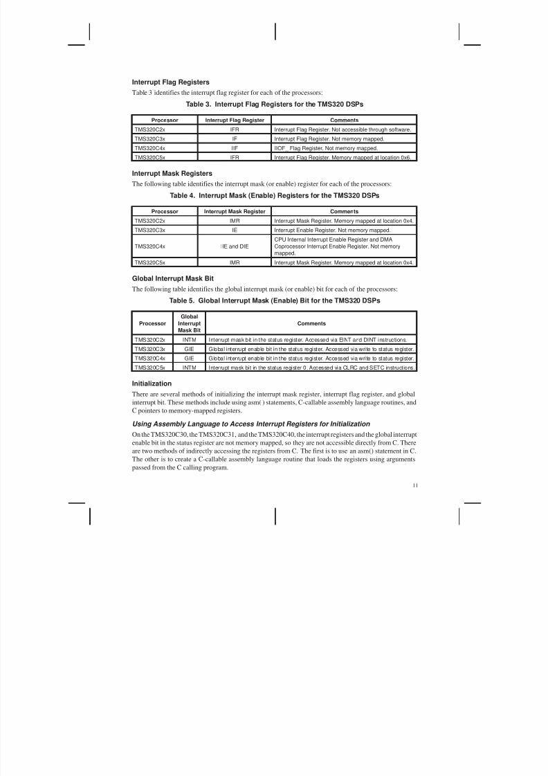
Interrupt Flag Registers 11. . . . . . . . . . . . . . . . . . . . . . . . . . . . . . . . . . . . . . . . . . . . . . . . . . . . . . . .
Interrupt Mask Registers 11. . . . . . . . . . . . . . . . . . . . . . . . . . . . . . . . . . . . . . . . . . . . . . . . . . . . . . .
Global Interrupt Mask Bit 11. . . . . . . . . . . . . . . . . . . . . . . . . . . . . . . . . . . . . . . . . . . . . . . . . . . . . .
Initialization 11. . . . . . . . . . . . . . . . . . . . . . . . . . . . . . . . . . . . . . . . . . . . . . . . . . . . . . . . . . . . . . . . .
Using Assembly Language to Access Interrupt Registers for Initialization 11. . . . . . . . . . . . . .
Using C Pointers to Memory-Mapped Registers for Initialization 12. . . . . . . . . . . . . . . . . . . . .
Enabling Interrupt Sources 13. . . . . . . . . . . . . . . . . . . . . . . . . . . . . . . . . . . . . . . . . . . . . . . . . . . . . . . .
Summary 13. . . . . . . . . . . . . . . . . . . . . . . . . . . . . . . . . . . . . . . . . . . . . . . . . . . . . . . . . . . . . . . . . . . . . . . .
5/17/2018 Setting Up Interupts in C - slidepdf.com
http://slidepdf.com/reader/full/setting-up-interupts-in-c 7/45
iv
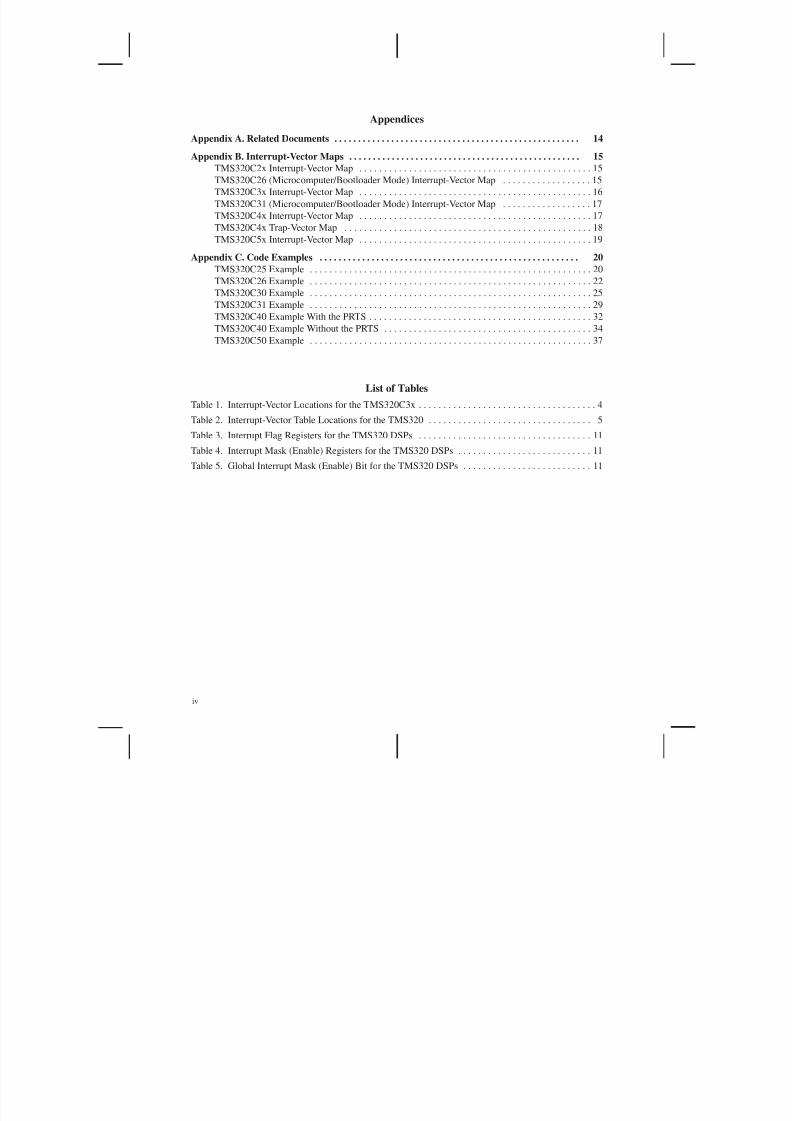
Appendices
Appendix A. Related Documents 14. . . . . . . . . . . . . . . . . . . . . . . . . . . . . . . . . . . . . . . . . . . . . . . . . . . .
Appendix B. Interrupt-Vector Maps 15. . . . . . . . . . . . . . . . . . . . . . . . . . . . . . . . . . . . . . . . . . . . . . . . .
TMS320C2x Interrupt-Vector Map 15. . . . . . . . . . . . . . . . . . . . . . . . . . . . . . . . . . . . . . . . . . . . . . .
TMS320C26 (Microcomputer/Bootloader Mode) Interrupt-Vector Map 15. . . . . . . . . . . . . . . . . .
TMS320C3x Interrupt-Vector Map 16. . . . . . . . . . . . . . . . . . . . . . . . . . . . . . . . . . . . . . . . . . . . . . .
TMS320C31 (Microcomputer/Bootloader Mode) Interrupt-Vector Map 17. . . . . . . . . . . . . . . . . .
TMS320C4x Interrupt-Vector Map 17. . . . . . . . . . . . . . . . . . . . . . . . . . . . . . . . . . . . . . . . . . . . . . .
TMS320C4x Trap-Vector Map 18. . . . . . . . . . . . . . . . . . . . . . . . . . . . . . . . . . . . . . . . . . . . . . . . . .
TMS320C5x Interrupt-Vector Map 19. . . . . . . . . . . . . . . . . . . . . . . . . . . . . . . . . . . . . . . . . . . . . . .
Appendix C. Code Examples 20. . . . . . . . . . . . . . . . . . . . . . . . . . . . . . . . . . . . . . . . . . . . . . . . . . . . . . .
TMS320C25 Example 20. . . . . . . . . . . . . . . . . . . . . . . . . . . . . . . . . . . . . . . . . . . . . . . . . . . . . . . . .
TMS320C26 Example 22. . . . . . . . . . . . . . . . . . . . . . . . . . . . . . . . . . . . . . . . . . . . . . . . . . . . . . . . .
TMS320C30 Example 25. . . . . . . . . . . . . . . . . . . . . . . . . . . . . . . . . . . . . . . . . . . . . . . . . . . . . . . . .
TMS320C31 Example 29. . . . . . . . . . . . . . . . . . . . . . . . . . . . . . . . . . . . . . . . . . . . . . . . . . . . . . . . .TMS320C40 Example With the PRTS 32. . . . . . . . . . . . . . . . . . . . . . . . . . . . . . . . . . . . . . . . . . . . .
TMS320C40 Example Without the PRTS 34. . . . . . . . . . . . . . . . . . . . . . . . . . . . . . . . . . . . . . . . . .
TMS320C50 Example 37. . . . . . . . . . . . . . . . . . . . . . . . . . . . . . . . . . . . . . . . . . . . . . . . . . . . . . . . .
List of Tables
Table 1. Interrupt-Vector Locations for the TMS320C3x 4. . . . . . . . . . . . . . . . . . . . . . . . . . . . . . . . . . . .
Table 2. Interrupt-Vector Table Locations for the TMS320 5. . . . . . . . . . . . . . . . . . . . . . . . . . . . . . . . .
Table 3. Interrupt Flag Registers for the TMS320 DSPs 11. . . . . . . . . . . . . . . . . . . . . . . . . . . . . . . . . . .
Table 4. Interrupt Mask (Enable) Registers for the TMS320 DSPs 11. . . . . . . . . . . . . . . . . . . . . . . . . . .Table 5. Global Interrupt Mask (Enable) Bit for the TMS320 DSPs 11. . . . . . . . . . . . . . . . . . . . . . . . . .
5/17/2018 Setting Up Interupts in C - slidepdf.com
http://slidepdf.com/reader/full/setting-up-interupts-in-c 8/45
1
Introduction
One of the inherent differences between a digital signal processor (DSP) and other processors is the DSP’s
ability to receive and service multiple sources of interrupts very quickly. These interrupt sources can betimers for setting up different time bases, external analog-to-digital converters for converting analog audio
signals into digital data, or on-chip coprocessors indicating a task is complete. Typically, when an interrupt
occurs, ordinary processing stops and an interrupt service routine (ISR) starts executing. The ISR’s
function is to store the contents of critical registers, perform the processing required by the interrupt, restore
the register contents, and restart the interrupted process. Interrupt sources on the TMS320 family of DSPs
include:
• Reset
• External interrupt pins
• On-chip peripherals
• On-chip DMA (direct memory access)
• Traps (software interrupts)
A DSP user’s guide defines exactly how that DSP reacts to an interrupt. Specifically, that definitionincludes:
• The interrupt latency – the time it takes from the occurrence of the interrupt (for example, a low
pulse on an external interrupt pin) to the execution of the first instruction in the ISR
• The interrupt priorities
• Conditions during the ISR, such as the ability to accept another interrupt
The user’s guide also explains how to set up the DSP to handle interrupts. It explains what registers need
to be initialized and what memory location needs to be initialized with the address of the ISR. This can be
done in either the native assembly language or in a high-level language.
Programming DSPs in a high-level language such as C provides for portability and maintainability. A
program can be rapidly prototyped and proven in C and then optimized to a particular processor
architecture. Often, the real-time or time-critical portions of the code are hand assembled in this
optimization process, resulting in high-performance code that is also efficient and readable.
Texas Instruments offers optimizing ANSI C compilers for the TMS320C2x, TMS320C3x, TMS320C4x,
and TMS320C5x DSPs. The compilers produce efficient code for these high-performance processors.
While these DSPs differ, setting up interrupts is similar for each of them. The main steps for setting up
interrupts for TMS320 DSPs are:
1. Create the interrupt service routines.
2. Initialize the vector table and set up the vectors in the memory map.
3. Enable the interrupts to the CPU.
4. Enable the interrupt sources.

5/17/2018 Setting Up Interupts in C - slidepdf.com
http://slidepdf.com/reader/full/setting-up-interupts-in-c 9/45
2
This document describes methods of setting up interrupts for these processors in C. When C cannot be used,
C-callable assembly language routines or in-line C statements are used. Topics covered in this document
include:
• C in-line assembly language• C-callable assembly language modules
• Assigning symbols at link time
• ’C40 parallel runtime-support library (PRTS)
• Initializing peripherals in C
• Individual placement of C variables/arrays in a DSP memory map
• Installing interrupt vectors at run time
• Accessing memory-mapped CPU registers in C
Sample code segments are given throughout this document, and Appendix C contains complete examples
of how to set up interrupt vectors for all the processors discussed herein.
Creating an Interrupt Service Routine
The first step in setting up interrupts in C is to define the ISR. The ISR is no different from an ordinary C
subroutine except for the name of the routine.
Naming Convention
By naming the subroutine c_intnn, where nn can be 00 to 99, the floating-point DSP C compiler can identify
the routine as an ISR and can follow different rules for saving and restoring registers. Ordinary routines
save and restore registers that are used by the routine according to the rules defined in the appropriate C
compiler manual. Interrupt service routines need to save and restore every register that is used by the ISR.
The next example shows an ISR defined in C:
void c_int11(void)
{
receiveCounter++;
}
For readability, it is possible to use a macro definition to rename c_intnn with a more descriptive name.
For example:
#define serialPortReceiveISR c_int11void serialPortReceiveISR(void){
receiveCounter++;}
For the fixed-point DSP C compiler, the ISR name must be c_intn, where n can be 0 to 9. Also, in the
fixed-point DSP C compiler, all of the registers are saved and restored, using the runtime-support library
functions I$$SAVE and I$$REST . However, in version 6.50 of the fixed-point DSP C compiler, the keyword
interrupt can be used instead of c_intn. For example:
interrupt void serialPortReceive ISR (void)
{
.
.
.
}
5/17/2018 Setting Up Interupts in C - slidepdf.com
http://slidepdf.com/reader/full/setting-up-interupts-in-c 10/45
3
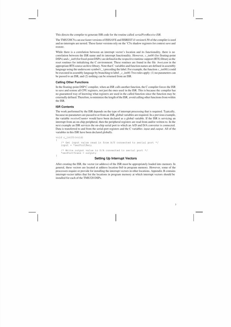
This directs the compiler to generate ISR code for the routine called serialPortReceive ISR.
The TMS320C5x can use faster versions of I$$SAVE and I$$REST if version 6.50 of the compiler is used
and no interrupts are nested. These faster versions rely on the ’C5x shadow registers for context save andrestore.
While there is a correlation between an interrupt vector’s location and its functionality, there is no
correlation between the ISR name and its interrupt functionality. However, c_int00 (for floating-point
DSPs) and c_int0 (for fixed-point DSPs) are defined in the respective runtime-support (RTS) library as the
reset routines for initializing the C environment. These routines are found in the file boot.asm in the
appropriate RTS source archive library. Note that C variables and function names are defined in assembly
language using the underscore symbol (_ ) preceding the label. For example, the function c_int00() could
be executed in assembly language by branching to label _c_int00. Two rules apply: (1) no parameters can
be passed to an ISR, and (2) nothing can be returned from an ISR.
Calling Other Functions
In the floating-point DSP C compiler, when an ISR calls another function, the C compiler forces the ISRto save and restore all CPU registers, not just the ones used in the ISR. This is because the compiler has
no guaranteed way of knowing what registers are used in the called function since the function may be
externally defined. Therefore, to minimize the length of the ISR, avoid calling other functions from within
the ISR.
ISR Contents
The work performed by the ISR depends on the type of interrupt processing that is required. Typically,
because no parameters are passed to or from an ISR, global variables are required. In a previous example,
the variable receiveCounter would have been declared as a global variable. If the ISR is servicing an
interrupt from an on-chip peripheral, then the peripheral registers are read from and/or written to. In the
next example an ISR services the on-chip serial port to which an A/D and D/A converter is connected.
Data is transferred to and from the serial-port registers and the C variables input and output . All of the
variables in this ISR have been declared globally.
void c_int05(void){
/* Get input value read in from A/D connected to serial port */input = *serPortRec;
/* Write output value to D/A connected to serial port */*serPortTrans = output;
}
Setting Up Interrupt Vectors
After creating the ISR, the vector (or address) of the ISR must be appropriately loaded into memory. In
general, these vectors are located at address location 0x0 in program memory. However, some of the
processors require or provide for installing the interrupt vectors in other locations. Appendix B contains
interrupt-vector tables that list the locations in program memory at which interrupt vectors should be
installed for each of the TMS320 DSPs.

5/17/2018 Setting Up Interupts in C - slidepdf.com
http://slidepdf.com/reader/full/setting-up-interupts-in-c 11/45
4
Table 1 shows a portion of the TMS320C3x interrupt-vector table.
Table 1. Interrupt-Vector Locations for the TMS320C3x
Interrupt Memory Location Function
RESET 0x0 External Reset
INT0_ 0x1 External Interrupt 0
INT1_ 0x2 External Interrupt 1
INT2_ 0x3 External Interrupt 2
INT3_ 0x4 External Interrupt 3
XINT0 0x5 Serial Port 0 Transmit
RINT0 0x6 Serial Port 0 Receive
⋅
⋅
⋅
⋅
⋅
⋅
⋅
⋅
⋅
Vector Table Locations
For the TMS320C25, the TMS320C26 in microprocessor mode, the TMS320C28, the TMS320C30, and
the TMS320C31 in microprocessor mode, the vectors always start at location 0x0. For the TMS320C31
in microcomputer/bootloader mode, the vectors start at location 0x809fc1. For the TMS320C26 in
microcomputer/bootloader mode, the vectors start at location 0xffa0. For the TMS320C5x, reset is always
at location 0x0, but the interrupt vectors can reside on any 2K-word page in program memory. The vector
table location is related to the value of the IPTR bits of the PMST register. Valid interrupt-vector-table base
addresses for the TMS320C5x are 0x0, 0x800, 0x1000, 0x1800, 0x2000, ..., 0xf800.
For the TMS320C4x, reset can be located at one of four locations as defined by the external pins
RESETLOC0 and RESETLOC1. The TMS320C4x’s interrupt vectors can reside on any 512-word
boundary in memory. The vector table location is defined by the value of the word stored in the IVTP
(interrupt vector table pointer) register. Additionally, The TMS320C4x’s trap interrupt vectors can resideon any 512-word boundary in memory. The trap vector table location is defined by the value of the word
stored in the TVTP (trap vector table pointer) register. Valid interrupt-, or trap-, vector-table base addresses
for the TMS320C4x are 0x0, 0x200, 0x400, 0x600, 0x800, 0xa00, 0xc00, 0xe00, 0x1000, 0x1200, ...,
0xfffffe00.

5/17/2018 Setting Up Interupts in C - slidepdf.com
http://slidepdf.com/reader/full/setting-up-interupts-in-c 12/45
5
This information is summarized in Table 2. For further explanation and detail, refer to the appropriate
device user’s guide.
Table 2. Interrupt-Vector Table Locations for the TMS320 DSPs
ProcessorVector Table
Base AddressComments
TMS320C2x 0x0Not including TMS320C26 in
microcomputer/bootloader mode
TMS320C26 0xffa0 Microcomputer/bootloader mode
TMS320C30 0x0
TMS320C31 0x0 Microprocessor mode
TMS320C31 0x809fc1 Microcomputer/bootloader mode
Reset0x0, 0x7fff ffff,
0x8000 0000, 0xfff ffff
Reset vector location defined by external pins
RESETLOC0 and RESETLOC1
TMS320C4x Interrupt Vectors Any 512-word boundary Interrupt-vector-table base address defined byvalue in IVTP register
Trap Vectors Any 512-word boundaryTrap-vector-table base address defined by value
in TVTP register
Reset 0x0
TMS320C5xInterrupt Vectors Any 2K-word page
Related to value of IPTR bits of the PMST
register
There are two methods of placing the interrupt vectors in the memory map at the appropriate location.
These two methods are described in the following sections.
Method I: Using a Named ASM Section
The more straightforward method for appropriately placing interrupt vectors is to create a table in assembly
language using the named-section assembler directive .sect . This table contains the addresses of theinterrupt vectors or branch-to-address instructions.
The TMS320C2x, the TMS320C5x, and the TMS320C31 in microcomputer/bootloader mode execute the
code at the interrupt vector locations. Therefore, branch-to-address instructions must be used as interrupt
vectors. For the TMS320C31 in microcomputer/bootloader mode, use the 24-bit branch instruction BR to
enable branching to any location in the address space. For example, on the TMS320C31, interrupt vector
1 could be defined in assembly language as follows:
INT1: br _c_int01
On the TMS320C30, the TMS320C31 in microprocessor mode, and the TMS320C4x, the value at the
interrupt vector is used as the address of the next instruction to be fetched. Therefore, the address of the
appropriate ISR must be stored at the interrupt vector location using the .word assembler directive. For
example, on the TMS320C4x, interrupt vector 1 could be defined in assembly language as follows:INT1: .word _c_int01
Note the underscore symbol (_) preceding the c_int01 function name in the previous two examples.
Because the ISR labels are declared external to the assembly language module, the labels must be declared
as .ref or .global. Following is an example of an assembly language module, vecs.asm, that defines a named
section containing TMS320C5x branch-to-address vectors:

5/17/2018 Setting Up Interupts in C - slidepdf.com
http://slidepdf.com/reader/full/setting-up-interupts-in-c 13/45
6
.ref _cint0, _c_int9 ;reference interrupt vectors defined externally
.sect ”vectors” ;declare a named section ”vectors”RS: b _c_int0 ;branch to reset vectorI1: b _c_int9 ;branch to interrupt vector 1I2: b _c_int9 ;branch to interrupt vector 2
Handling Reserved and Unused Locations
Sometimes the interrupt vector table contains reserved locations, as in the case of the TMS320C26 in
microcomputer/bootloader mode or the case of noncontinguous TMS320C4x or TMS320C5x reset and
interrupt vectors. This also occurs on spinoff devices with different peripherals, such as the TMS320C31.
Also, your system may not use all of the interrupts available. To handle these holes in the vector map, the
.space assembler directive can be used. Note that on the fixed-point devices, .space reserves bits, while on
the floating-point devices, .space reserves words. For example, on the TMS320C26 in
microcomputer/bootloader mode, if you were to use every interrupt available, your vector map might look
like this:
.sect ”vectors” ;define named section
;for reset & interrupt vectors.space 2*16 ;reservedb _c_int1 ;INT0b _c_int2 ;INT1b _c_int3 ;INT2b _c_int4 ;TINTb _c_int5 ;RINTb _c_int6 ;XINTb _c_int7 ;TRAP
Note that the .space directive reserves one location for the reset vector that is not employed in bootloader
mode because reset invokes the bootloader in microcomputer/bootloader mode. Here, the section vectorswould be linked to location 0xfa00. Alternatively, the .space directive could have been removed and the
section linked to location 0xfa02.
If, however, only the timer and trap interrupt vectors are to be used, the vector map could be defined as
follows using the .space directive:
.sect ”vectors” ;define named section;for reset & interrupt vectors
.space 2*4*16 ;reserved and 3 unused vectorsb c_int4 ;TINT.space 2*2*16 ;2 unused vectorsb _c_int7 ;TRAP
Note that the unused portions of the interrupt or trap vector table can be used to store data values. However,
to ensure that interrupts are handled correctly, make sure that the used interrupt or trap vectors are not
corrupted.
Linking Into the Memory Map
Once the named section is created, the name of the section (vectors in the last example) can be used as a
handle to link the table to the appropriate location in the memory map using the TMS320 linker(LNK30.EXE or DSPLNK.EXE, for floating-point or fixed-point DSPs, respectively). There are three
steps to this:
1. Link in the assembly language module.
2. Define a linker MEMORY section corresponding to the interrupt vector locations.
3. Use the linker SECTIONS area to place the named section into the previously defined
MEMORY section.

5/17/2018 Setting Up Interupts in C - slidepdf.com
http://slidepdf.com/reader/full/setting-up-interupts-in-c 14/45
7
The following is a linker command file segment for the TMS320C5x. It links a named section vectors to
location 040h.
–c.vecs.obj /* (1) Link in the vector table */main.obj.–lrts50.lib
MEMORY{
PAGE0:VECTORS: origin = 0000h, length = 0003fh /* (2) Declare mem for vectors */
ROM: origin = 0040h, length = 007cfh
.
}
SECTIONS{
”vectors”: {} > VECTORS /* (3) Place vector table */.text: {} > ROM
.}
Bootloader
When using the bootloader on the TMS320 DSPs, the default entry point for code execution is the
destination address of the first word transferred by the on-chip bootloader. The hex conversion bootloader
utilities (HEX30.EXE and DSPHEX.EXE) have provisions for overriding this entry point and defining it
to be the address of the reset routine. When using the device in bootloader mode, there is no reset ISR;
instead, resetting the device causes the bootloader to execute.
Method II: Installing a Run-Time Vector
Another method that is useful during development and debugging is installing the vectors at run time by
loading the address of the ISR into the proper location using a C statement. This is appropriate only for the
TMS320C30, the TMS320C31 in microprocessor mode, and the TMS320C4x, because they use addressesand not branch-to-address instructions as interrupt vectors. The intention is to use a C typecast to put the
address of the ISR into the desired memory location. For example, on the TMS320C30, location 0x1
corresponds to external interrupt 0 (INT0). To install the ISR c_int01() there, use the following statement:
*((void (**) ()) 0x1) = c_int01;
Here, location 0x1 is being typecasted as a pointer to a function, because it contains the address of the
function c_int01(). The danger is that the C programmer might overwrite data or program memory that is
allocated by the linker.
Vector Table Pointers
The TMS320C5x and TMS320C4x devices have provisions for placing interrupt vectors in locations other
than 0x0. Both have registers to enable the processor to identify the location of the vectors. The
TMS320C4x can also define the reset vector to reside in one of four locations, as determined by pins onthe processor. For interrupts to be processed correctly, their interrupt-vector-table pointers must be
initialized prior to receiving any interrupts. The following four examples illustrate techniques for
initializing these registers.

5/17/2018 Setting Up Interupts in C - slidepdf.com
http://slidepdf.com/reader/full/setting-up-interupts-in-c 15/45
8
Example 1. Using a C In-Line ASM Statement on the TMS320C4x
This example uses C in-line assembly language instructions to set the TMS320C4x interrupt vectors to start
at location 0x0 by setting the value of the IVTP register to 0x0 in a hard-coded fashion.
asm(“\t PUSH \t r0”);asm(“\t LDI \t 0h, r0”);asm(“\t LDPE \t r0, \vtp”);asm(“\t POP \t r0”);
The backslash t (\t) is used to insert tabs in the assembly language instruction.
Example 2. Using the TMS320C4x PRTS
This example uses the TMS320C4x parallel runtime-support library to set the TMS320C4x interrupt
vectors to start at location 0x02ff800, the start of RAM block 0, by setting the value of the IVTP register
using the set_ivtp() PRTS library function. When using the PRTS, no named section of interrupt vectors
is required from the user. Instead, the install_int_vector() PRTS function is used to install vectors at run
time into the predefined section .vector . In this method, vectors are installed at run time in a way that ensuresthat no program or data will be overwritten. First, the PRTS library is linked to the program, and the
predefined section .vector is allocated to reside at the start of RAM block 0 using a linker command file
as follows:
.–lprts40.lib.MEMORY{
RAM0: org = 0x2ff800 len = 0x400 /* RAM Block 0 */.
}SECTIONS{
”.vector”: {} > RAM0 /* Allocate space for interrupt */
. /* vectors for C40 PRTS */.}
The main program must include the header file intpt40.h. The set_ivtp() function can now be called using
the predefined argument DEFAULT, which sets the ivtp to the address of the section .vector as defined in
the linker command file above. The interrupt vectors can be installed using the install_int_vector()function as follows:
#include <intpt40.h>
void c_int99(void){
for(;;);}
void main(void)
{ set_ivtp(DEFAULT); /* Initialize the IVTP *//* register */
install_int_vector((void *) c_int99, 2); /* Install timer interrupt */.
}

5/17/2018 Setting Up Interupts in C - slidepdf.com
http://slidepdf.com/reader/full/setting-up-interupts-in-c 16/45
9
Example 3. Using Memory-Mapped Registers on the TMS320C5x
The following example sets the TMS320C5x interrupt vectors to start at location 0x800 by hard coding the
value of the IPTR bits of the PMST register to 0x800 in C using a pointer to the memory-mapped register,PMST, which is located at address 0x7.
unsigned int *pmst = (unsigned int *) 0x7; /* PMST register */*pmst | = 0x800; /* Initialize IPTR bits of PMST */
Example 4. Assigning Symbols at Link Time on Either the TMS320C4x or theTMS320C5x
While the TMS320C5x C compiler does not have a PRTS library to assist in setting up the vector-table
pointer registers, there is a flexible, portable method for accomplishing the same task on both the
TMS320C4x and TMS320C5x. This method employs assigning symbols at link time.
The idea is to use an assembly language section (.sect ) that contains reset and interrupt vectors and use the
linker to map to the location of the placement of the interrupt vectors in memory. This address is made
accessible to the C program and can be loaded into the interrupt vector table pointer on the TMS320C4x(IVTP register) or the PMST register on the TMS320C5x.
Start by defining the interrupt vectors in an assembly language module. Following is an example using the
TMS320C5x. To access the address of the interrupt vectors, a label is used to locate the base address of the
interrupt-vector table. In this example, IVECS is used as the label.
.def IVECS ;IVECS defined in this module
.ref _c_int0, _c_int1, c_int2 ;reference all interrupt;vectors declared elsewhere
*************** Reset vector**************
.sect ”reset” ;define named section for;reset vector
b _c_int0 ;reset vector
******************** Interrupt vectors*******************
.sect ”vectors” ;define named section;for interrupt vectors
IVECS .space 2 ;one reserved locationb _c_int1 ;interrupt vector 1b _c_int2 ;interrupt vector 2

5/17/2018 Setting Up Interupts in C - slidepdf.com
http://slidepdf.com/reader/full/setting-up-interupts-in-c 17/45
10
In the linker, use a linker-assigned label to initialize a linker-defined variable. In this case, the label IVECSis assigned to a variable. Continuing the last example:
–cvecs.obj..–lrts50.lib
_vecTable = IVECS ;/* set vecTable to point to vector table */
MEMORY{
PAGE 0: VECTORS: origin = 00000h, length = 0003fhROM: origin = 00040h, length = 007CFhP_RAM: origin = 00800h, length = 023FFh
.
.}SECTIONS{
”reset” > VECTORS”vectors” > P_RAM.text: > ROM.cinit: > ROM.bss: > RAMB0_D.stack: > INT_RAM
}
In the C program, declare the pointer to unsigned integer vecTable to be extern as follows:
extern unsigned int *vecTable;
Now it can be loaded into the PMST register as follows:
unsigned int *pmst = (unsigned int *) 0x07; /* PMST register */*pmst |= (unsigned int) vecTable;
Using this method on the TMS320C5x or the TMS320C4x provides a flexible approach to loading thevector-table-pointer registers so that when the vector table is relocated in the linker command file, the C
program does not need to be recompiled, only relinked.
Enabling Interrupts
Before interrupts can be processed, they must be enabled. There are two places that interrupts are enabled.
All the processors described in this document have both an interrupt mask register (or interrupt enable
register) and a global interrupt enable bit in the status register. The interrupt mask register provides
individual control of each interrupt source to the CPU. The global interrupt mask (or enable) bit provides
a master switch to turn all interrupts on and off. This bit is usually enabled once by the programmer at the
beginning of the program. During interrupt processing, this bit is toggled off by the interrupt processing
logic and toggled on by the return-from-interrupt instruction that ends the ISR. This is done to prevent an
ISR from being preempted. The user can override this by re-enabling global interrupts in the ISR.
Each processor also has an interrupt flag register. The individual bits of this register are automatically set
when an interrupt occurs. They are automatically cleared when an interrupt is taken. It is customary to clear
this register before enabling interrupts for the first time; however, in the TMS320C2x family, this register
is not accessible through software. For the TMS320C3x and TMS320C4x processors, the register should
be loaded with 0x0 to clear all interrupts. On the TMS320C5x, write a 1 to each bit to clear the interrupts.
5/17/2018 Setting Up Interupts in C - slidepdf.com
http://slidepdf.com/reader/full/setting-up-interupts-in-c 18/45
11
Interrupt Flag Registers
Table 3 identifies the interrupt flag register for each of the processors:
Table 3. Interrupt Flag Registers for the TMS320 DSPs
Processor Interrupt Flag Register Comments
TMS320C2x IFR Interrupt Flag Register. Not accessible through software.
TMS320C3x IF Interrupt Flag Register. Not memory mapped.
TMS320C4x IIF IIOF_ Flag Register. Not memory mapped.
TMS320C5x IFR Interrupt Flag Register. Memory mapped at location 0x6.
Interrupt Mask Registers
The following table identifies the interrupt mask (or enable) register for each of the processors:
Table 4. Interrupt Mask (Enable) Registers for the TMS320 DSPs
Processor Interrupt Mask Register Comments
TMS320C2x IMR Interrupt Mask Register. Memory mapped at location 0x4.
TMS320C3x IE Interrupt Enable Register. Not memory mapped.
TMS320C4x IIE and DIE
CPU Internal Interrupt Enable Register and DMA
Coprocessor Interrupt Enable Register. Not memory
mapped.
TMS320C5x IMR Interrupt Mask Register. Memory mapped at location 0x4.
Global Interrupt Mask Bit
The following table identifies the global interrupt mask (or enable) bit for each of the processors:
Table 5. Global Interrupt Mask (Enable) Bit for the TMS320 DSPs
Processor
Global
Interrupt
Mask Bit
Comments
TMS320C2x INTM Interrupt mask bit in the status register. Accessed via EINT and DINT instructions.
TMS320C3x GIE Global interrupt enable bit in the status register. Accessed via write to status register.
TMS320C4x GIE Global interrupt enable bit in the status register. Accessed via write to status register.
TMS320C5x INTM Interrupt mask bit in the status register 0. Accessed via CLRC and SETC instructions.
Initialization
There are several methods of initializing the interrupt mask register, interrupt flag register, and global
interrupt bit. These methods include using asm( ) statements, C-callable assembly language routines, and
C pointers to memory-mapped registers.
Using Assembly Language to Access Interrupt Registers for Initialization
On the TMS320C30, the TMS320C31, and the TMS320C40, the interrupt registers and the global interrupt
enable bit in the status register are not memory mapped, so they are not accessible directly from C. There
are two methods of indirectly accessing the registers from C. The first is to use an asm() statement in C.
The other is to create a C-callable assembly language routine that loads the registers using arguments
passed from the C calling program.

5/17/2018 Setting Up Interupts in C - slidepdf.com
http://slidepdf.com/reader/full/setting-up-interupts-in-c 19/45
12
The asm() statement embeds the assembly language statement directly into the C program in a hard-coded
fashion. The next example illustrates the use of the asm() statement to set these registers on the
TMS320C3x:
void main(void){
asm(”\t LDI \t 0h,IF”); /* Clear IF register */asm(”\t OR \t 3h,IE”); /* Enable external interrupts 0 and 1 */asm(”\t OR \t 2000h,ST”); /* Enable interrupts globally */.
}
On the TMS320C2x and TMS320C5x processors, the interrupt mask bit, INTM, of the status register
controls all interrupts globally. This bit is cleared to enable interrupts using the EINT assembly language
instruction on the TMS320C2x and the CLRC assembly language instruction on the TMS320C5x. The
following code illustrates the use of the asm( ) statement to clear the INTM bit on the TMS320C5x:
void main(void){
asm(”\t CLRC \t INTM”);/* Enable interrupts globally */
.}
The second and preferred method, using C-callable assembly language routines, leads to more reusable
code. For example, on the TMS320C40, the value for the interrupt enable register IIE could be passed to
a C-callable routine, initIIE(), defined as follows:
_initIIE:PUSH FP ;manage stack on entryLDI SP,FP
LDI *–FP(2),IIE ;load int enable register
LDI *–FP(1),R1 ;manage stack on exitBD R1LDI *FP,FPNOPSUBI 2,SP
*** B R1 ;branch occurs
The function prototype for the C-callable assembly language routine is:
extern void initIIE(unsigned int);
and an example of calling the routine is shown below:
initIIE(0x1);/* Enable Timer 0 interrupt */
Using C Pointers to Memory-Mapped Registers for Initialization
On the TMS320C2x and TMS320C5x processors, the interrupt mask and flag registers are memory
mapped. Hence, a C pointer can be used to access these registers directly from C. However, the INTM bit
must be accessed as described in the previous section. The next example initializes the TMS320C5x
interrupt registers in C using C pointers:
void main(void)
{unsigned int *imr = (unsigned int *) 0x4; /*Declare pointer to IMR register /*
volatile unsigned int *ifr =
(volatile unsigned int *) 0x6; /*Declare pointer to IFR register */
*imr |= 0x3; /*Enable external interrupts 1 and 2 */
*ifr = 0x01ff; /*(Optionally) clear all interrupts */
.
}

5/17/2018 Setting Up Interupts in C - slidepdf.com
http://slidepdf.com/reader/full/setting-up-interupts-in-c 20/45
13
Note the use of the qualifier volatile in the declaration of the pointer ifr . This is used to point to elements
(in this case, the ifr register) that can change independently of code execution.
Enabling Interrupt Sources
After the interrupt vectors have been installed and the interrupts have been enabled, the interrupt sources
can be enabled. For on-chip resources such as timers, serial ports, and DMA, this amounts to starting the
on-chip resource as described in the device user’s guide. These on-chip resources are configured and started
using memory-mapped registers. The following example illustrates a routine for starting the TMS320C31
on-chip DMA to transfer data and cause an interrupt. It uses the TMS320C30 peripheral control library.
#include “dma30.h”
extern int sourceArray[];extern int destArray[];
void setupDMA(void){
volatile DMA_REG * dma = DMA_ADDR:dma–>gcontrol = 0x0; /* Stop the DMA and init to 0 */dma–>source = (unsigned) sourceArray; /* Load DMA source address */dma–>=destination = *unsigned) destArray; /* Load DMA destination address */dma–>transfer_counter = 5; /* Load DMA transfer count *//* Start DMA to transfer data, stop and cause a CPU interrupt */dma–>gcontrol = START3 | INCSRC | INCDST | TCINT | TC;
Summary
This document describes various techniques to set up and initialize interrupts on the TMS320 DSPs using
C wherever possible. C can be used to create the interrupt service routine and initialize any
memory-mapped registers related to interrupts. It can also be used to install the vectors at run time.
However, using a named assembly language section is the preferred method. Where memory-mappedregisters are not provided, it is recommended that a C-callable assembly language routine that accepts
register values as inputs be used to initialize those registers. Finally, the TMS320C4x C compiler provides
a parallel runtime-support library to handle interrupts entirely in C.

5/17/2018 Setting Up Interupts in C - slidepdf.com
http://slidepdf.com/reader/full/setting-up-interupts-in-c 21/45
14
Appendix A. Related Documents
The following documents provide additional information on this and other DSP- or C-related topics:
1. TMS320C2x User’s Guide, SPRU014.2. TMS320C3x User’s Guide, SPRU031.
3. TMS320C4x User’s Guide, SPRU063.
4. TMS320C5x User’s Guide, SPRU056.
5. TMS320C2x/ C2xx/C5x Optimizing C Compiler User’s Guide, SPRU024.
6. TMS320C1x/C2x/C2xx/C5x Assembly Language Tools User’s Guide, SPRU018.
7. TMS320 Floating-Point DSP Optimizing C Compiler User’s Guide, SPRU034.
8. TMS320 Floating-Point DSP Assembly Language Tools User’s Guide , SPRU035.
9. Digital Signal Processor Applications With the TMS320C30 Evaluation Module, SPRA021.
10. TMS320C4x Parallel Runtime-Support Library Reference Guide, SPRU084.
11. TMS320C3x Peripheral Control Library User’s Guide, SPRU086.
12. The C Programming Language, Brian W. Kernighan and Dennis M. Ritchie, Prentice-Hall,
1988.
13. TMS320 Digital Signal Processor Designer’s Notebook Number 2: Avoiding False Interrupts
on the ’C3x.
14. TMS320 Digital Signal Processor Designer’s Notebook Number 21: TMS320C5x Interrupts.
15. TMS320 Digital Signal Processor Designer’s Notebook Number 24: TMS320C5x Interrupt
Response Time.
16. TMS320 Digital Signal Processor Designer’s Notebook Number 30: Addressing Peripherals as
Data Structures.
17. TMS320 Digital Signal Processor Designer’s Notebook Number 31: Interrupts in C on the
TMS320C3x.
18. TMS320 Digital Signal Processor Designer’s Notebook Number 35: TMS320C5x Interrupts
and the Pipeline.
19. TMS320 Digital Signal Processor Designer’s Notebook Number 36: Improved Context
Save/Restore Performance and Interrupts Latency for ISRs Written in C.

5/17/2018 Setting Up Interupts in C - slidepdf.com
http://slidepdf.com/reader/full/setting-up-interupts-in-c 22/45
15
Appendix B. Interrupt-Vector Maps
This appendix describes the interrupt-vector maps for the individual TMS320 DSPs discussed in this
document.
TMS320C2x Interrupt-Vector Map
The following interrupt-vector map applies to all TMS320C2x devices except the TMS320C26 in
microcomputer/bootloader mode.
Interrupt
Name
Memory
LocationFunction
RS_ 0x0 External Reset
INT0_ 0x2 External Interrupt 0
INT1_ 0x4 External Interrupt 1
INT2_ 0x6 External Interrupt 2
––––– 0x8 – 0x17 ReservedTINT 0x18 Timer Interrupt
RINT 0x1a Serial Port Receive Interrupt
XINT 0x1c Serial Port Transmit Interrupt
TRAP 0x1e TRAP Instruction Address
TMS320C26 (Microcomputer/Bootloader Mode) Interrupt-Vector Map
The following interrupt for interrupt-vector map applies to the TMS320C26 in microcomputer/bootloader
mode.
Interrupt
Name
Memory
LocationFunction
––––– 0xffa0 ReservedINT0_ 0xffa2 External Interrupt 0
INT1_ 0xffa4 External Interrupt 1
INT2_ 0xffa6 External Interrupt 2
TINT 0xffa8 Timer Interrupt
RINT 0xffaa Serial Port Receive Interrupt
XINT 0xffac Serial Port Transmit Interrupt
TRAP 0xffae TRAP Instruction Address

5/17/2018 Setting Up Interupts in C - slidepdf.com
http://slidepdf.com/reader/full/setting-up-interupts-in-c 23/45
16
TMS320C3x Interrupt-Vector Map
The following interrupt-vector map applies to all TMS320C3x devices except for the TMS320C31 in
microcomputer/bootloader mode.
Interrupt
Name
Memory
LocationFunction
RESET 0x0 External Reset
INT0_ 0x1 External Interrupt 0
INT1_ 0x2 External Interrupt 1
INT2_ 0x3 External Interrupt 2
INT3_ 0x4 External Interrupt 3
XINT0 0x5 Serial Port 0 Transmit Interrupt
RINT0 0x6 Serial Port 0 Receive Interrupt
XINT0† 0x7 Serial Port 1 Transmit Interrupt
RINT0†
0x8 Serial Port 1 Receive InterruptTINT0 0x9 Timer 0 Interrupt
TINT1 0xa Timer 1 Interrupt
DINT 0xb DMA Interrupt
––––– 0xc – 0x1f Reserved
TRAP 0 0x20 TRAP 0
TRAP 1 0x21 TRAP 1
. . .
. . .
. . .
TRAP 27 0x3b TRAP 27
––––– 0x3c – 0x3f Reserved
† Reserved on the TMS320C31

5/17/2018 Setting Up Interupts in C - slidepdf.com
http://slidepdf.com/reader/full/setting-up-interupts-in-c 24/45
17
TMS320C31 (Microcomputer/Bootloader Mode) Interrupt-Vector Map
The following interrupt-vector map applies to the TMS320C31 in microcomputer/bootloader mode.
InterruptName
Memory Location Function
INT0_ 0x809fc1 External Interrupt 0
INT1_ 0x809fc2 External Interrupt 1
INT2_ 0x809fc3 External Interrupt 2
INT3_ 0x809fc4 External Interrupt 3
XINT0 0x809fc5 Serial Port 0 Transmit Interrupt
RINT0 0x809fc6 Serial Port 0 Receive Interrupt
––––– 0x809fc7– 0x809fc8 Reserved
TINT0 0x809fc9 Timer 0 Interrupt
TINT1 0x809fca Timer 1 Interrupt
DINT 0x809fcb DMA Interrupt ––––– 0x809fcc – 0x809fdf Reserved
TRAP 0 0x809fe0 TRAP 0
TRAP 1 0x809fe1 TRAP 1
. . .
. . .
. . .
TRAP 27 0x809ffb TRAP 27
––––– 0x809ffc – 0x809fff Reserved
TMS320C4x Interrupt-Vector Map
The following interrupt-vector map applies to the TMS320C4x.
Interrupt Name Memory Location Function
––––– IVTP + 0x0 Reserved
NMI IVTP + 0x1 Nonmaskable Interrupt
TINT0 IVTP + 0x2 Timer 0 Interrupt
IIOF0_ IVTP + 0x3 External Interrupt 0
IIOF1_ IVTP + 0x4 External Interrupt 1
IIOF2_ IVTP + 0x5 External Interrupt 2
IIOF3_ IVTP + 0x6 External Interrupt 3
––––– IVTP + 0x7 to IVTP + 0xc Reserved
ICFULL0 IVTP + 0xd Input Channel 0 Full
ICRDY0 IVTP + 0xe Input Channel 0 Ready
OCRDY0 IVTP + 0xf Output Channel 0 Ready
OCEMPTY0 IVTP + 0x10 Output Channel 0 Empty
ICFULL1 IVTP + 0x11 Input Channel 1 Full
ICRDY1 IVTP + 0x12 Input Channel 1 Ready
OCRDY1 IVTP + 0x13 Output Channel 1 Ready
OCEMPTY1 IVTP + 0x14 Output Channel 1 Empty
5/17/2018 Setting Up Interupts in C - slidepdf.com
http://slidepdf.com/reader/full/setting-up-interupts-in-c 25/45
18
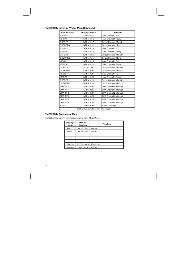
TMS320C4x Interrupt-Vector Map (Continued)
Interrupt Name Memory Location Function
ICFULL2 IVTP + 0x15 Input Channel 2 Full
ICRDY2 IVTP + 0x16 Input Channel 2 Ready
OCRDY2 IVTP + 0x17 Output Channel 2 Ready
OCEMPTY2 IVTP + 0x18 Output Channel 2 Empty
ICFULL3 IVTP + 0x19 Input Channel 3 Full
ICRDY3 IVTP + 0x1a Input Channel 3 Ready
OCRDY3 IVTP + 0x1b Output Channel 3 Ready
OCEMPTY3 IVTP + 0x1c Output Channel 3 Empty
ICFULL4 IVTP + 0x1d Input Channel 4 Full
ICRDY4 IVTP + 0x1e Input Channel 4 Ready
OCRDY4 IVTP + 0x1f Output Channel 4 Ready
OCEMPTY4 IVTP + 0x20 Output Channel 4 EmptyICFULL5 IVTP + 0x21 Input Channel 4 Full
ICRDY5 IVTP + 0x22 Input Channel 4 Ready
OCRDY5 IVTP + 0x23 Output Channel 4 Ready
OCEMPTY5 IVTP + 0x24 Output Channel 4 Empty
DMA INT0 IVTP + 0x25 DMA Channel 0 Interrupt
DMA INT1 IVTP + 0x26 DMA Channel 1 Interrupt
DMA INT2 IVTP + 0x27 DMA Channel 2 Interrupt
DMA INT3 IVTP + 0x28 DMA Channel 3 Interrupt
DMA INT4 IVTP + 0x29 DMA Channel 4 Interrupt
DMA INT5 IVTP + 0x2a DMA Channel 5 Interrupt
TINT1 IVTP + 0x2b Timer 1 Interrupt
––––– IVTP + 0x2c to IVTP + 0x3f Reserved
TMS320C4x Trap-Vector Map
The following trap-vector map applies to the TMS320C4x.
Interrupt
Name
Memory
LocationFunction
TRAP 0 TVTP + 0x0 TRAP 0
TRAP 1 TVTP + 0x1 TRAP 1
. . .
. . .
. . .
TRAP 510 TVTP + 0x1fe TRAP 510
TRAP 511 TVTP + 0x1ff TRAP 511

5/17/2018 Setting Up Interupts in C - slidepdf.com
http://slidepdf.com/reader/full/setting-up-interupts-in-c 26/45
19
TMS320C5x Interrupt-Vector Map
The following trap-vector map applies to the TMS320C5x devices.
Interrupt
NameMemory Location Function
RS_ 0x0 Reset
INT1_ IPTR + 0x2 External Interrupt 1
INT2_ IPTR + 0x4 External Interrupt 2
INT3_ IPTR + 0x6 External Interrupt 3
TINT IPTR + 0x8 Timer Interrupt
RINT IPTR + 0xa Serial Port Receive Interrupt
XINT IPTR + 0xc Serial Port Transmit Interrupt
TRNT† IPTR + 0xe TDM Port Receive Interrupt
TXNT† IPTR + 0x10 TDM Port Transmit Interrupt
INT4_ IPTR + 0x12 External Interrupt 4 ––––– IPTR + 0x14 to IPTR + 0x21 Reserved
TRAP IPTR + 0x22 TRAP Instruction Vector
NMI IPTR + 0x24 Nonmaskable Interrupt
––––– IPTR + 0x26 to IPTR + 0x3f Reserved
† Reserved on the TMS320C52

5/17/2018 Setting Up Interupts in C - slidepdf.com
http://slidepdf.com/reader/full/setting-up-interupts-in-c 27/45
20
Appendix C. Code Examples
This appendix provides complete examples for setting up interrupt vectors in C for the processors discussed
in this document.
TMS320C25 Example
The following TMS320C25 example uses C entirely except to globally enable registers and build the vector
table in memory. An asm() statement is used to enable the interrupts globally, and an assembly language
named section is used to create the vector table.
File: test.c
/**************************************************************************//* TEST.C – Test program *//**************************************************************************/
/**************************************************************************//* MAIN – Main routine *//**************************************************************************/void main(void){
initInts(); /* Initialize interrupts */
for(;;); /* Replace with real code */}
___________________________________________________________________________________
File: initvecs.c
/**************************************************************************//* INITVECS.C – Interrupt vector routines *//**************************************************************************/
#define globalEnableInt() asm(”\t EINT”);
/**************************************************************************//* initInts() – Initialize processor interrupt registers *//**************************************************************************/void initInts(void){
unsigned int *imr = (unsigned int *) 0x04; /* IMR register */*imr = 0x1; /* Enable INT0 */globalEnableInt();
}
/**************************************************************************//* C_INT9 – Interrupt service routine *//**************************************************************************/#define dummyISR c_int9 /* Rename ISR to correspond to TI */
/* naming conventions */void dummyISR(void){
for(;;); /* Replace with real ISR */
}

5/17/2018 Setting Up Interupts in C - slidepdf.com
http://slidepdf.com/reader/full/setting-up-interupts-in-c 28/45
21
File: vecs.asm
****************************************************************************** VECS.ASM – Reset and interrupt vector branch table for the C25 *
*****************************************************************************.title ”vecs.asm” ;file name.ref _c_int0,_c_int9 ;reference all interrupt
;vectors declared elsewhere
****************************** Reset and interrupt vectors*****************************
.sect ”vectors” ;define named section;for reset & interrupt vectors
b _c_int0 ;branch to reset vectorb _c_int9 ;branch to interrupt vector 1b _c_int9 ;branch to interrupt vector 2
___________________________________________________________________________________
File: test.cmd
/***************************************************************************//* TEST.CMD – C25 linker command file *//***************************************************************************/–cvecs.objinitvecs.objtest.obj–mtest.map–otest.out–stack 0x400–heap 0x400–lrts25.lib
MEMORY{
PAGE 0: VECTORS: origin = 00000h, length = 0002AhROM: origin = 00030h, length = 007CFhP_RAM: origin = 00800h, length = 02400hEXT_PRGM: origin = 02c00h, length = 05400h
PAGE 1: REGS: origin = 00000h, length = 00050hI_O: origin = 00050h, length = 00010hRAMB2: origin = 00060h, length = 00020hRAMB1: origin = 00300h, length = 00200hINT_RAM: origin = 00800h, length = 02400hEXT_DATA: origin = 08000h, length = 08000h
}SECTIONS{
”vectors”: { } > VECTORS.text: { } > P_RAM.cinit: { } > P_RAM.bss: { } > INT_RAM.stack: { } > INT_RAM
}

5/17/2018 Setting Up Interupts in C - slidepdf.com
http://slidepdf.com/reader/full/setting-up-interupts-in-c 29/45
22
TMS320C26 Example
The following TMS320C26 example is similar to the TMS320C25 example. For this example, a section
named bootvecs is used to emulate the vector remapping that occurs due to the TMS320C26 boot loader.File: test.c
/**************************************************************************//* TEST.C – Test program *//**************************************************************************/
/**************************************************************************//* MAIN – Main routine *//**************************************************************************/void main(void){
initInts(); /* Initialize interrupts */
for(;;); /* Replace with real code */}
___________________________________________________________________________________
File: initvecs.c
/**************************************************************************//* INITVECS.C – Interrupt vector routines *//**************************************************************************/
#define globalEnableInt() asm(”\t EINT”);
/**************************************************************************//* initInts() – Initialize processor interrupt registers *//**************************************************************************/void initInts(void){
unsigned int *imr = (unsigned int *) 0x04; /* IMR register */*imr = 0x1; /* Enable INT0 */globalEnableInt();
}
/**************************************************************************//* C_INT1 – Interrupt service routine *//**************************************************************************/#define dummyISR c_int1 /* Rename ISR to correspond to TI */
/* naming conventions */void dummyISR(void){
for(;;); /* Replace with real ISR */}

5/17/2018 Setting Up Interupts in C - slidepdf.com
http://slidepdf.com/reader/full/setting-up-interupts-in-c 30/45
23
File: vecs.asm
****************************************************************************** VECS.ASM – Reset and interrupt vector branch table for the C26 *
**********************************************************************************
.title ”vecs.asm” ;file name
.ref _c_int1 ;reference all interrupt;vectors declared elsewhere
****************************** Reset and interrupt vectors*****************************
.sect ”vectors” ;define named section;for reset & interrupt vectors
.space 2*16 ;reservedb _c_int1 ;branch to interrupt vector 1b _c_int1 ;branch to interrupt vector
___________________________________________________________________________________
File: boot.asm
********************************************************************* Boot.asm – file to emulate boot loader vector remmapping *********************************************************************
.sect ”bootvecs”PROG: .set 0FA00h ;Prog–Address of B0START B START,*,AR7 ;Reset
B PROG+2,*,AR0 ;Interrupt 0B PROG+4,*,AR0 ;Interrupt 1B PROG+6,*,AR0 ;Interrupt 2
.space 16 * 16 ;Reserve 16 WordsB PROG+8,*,AR0 ;Timer-InterruptB PROG+10,*,AR0 ;Serial-Port-Int.B PROG+12,*,AR0 ;Serial-Port-Int.B PROG+14,*,AR0 ;Software-Interrupt

5/17/2018 Setting Up Interupts in C - slidepdf.com
http://slidepdf.com/reader/full/setting-up-interupts-in-c 31/45
24
File: test.cmd
/***************************************************************************//* TEST.CMD – C26 linker command file */
/***************************************************************************/–cvecs.objboot.objinitvecs.objtest.obj–mtest.map–otest.out–stack 0x400–heap 0x400–lrts25.lib
MEMORY{
PAGE 0 : ROM: origin = 00000h, length = 007FFhP_RAM: origin = 00800h, length = 02400hVECTORS: origin = 0FA00h, length = 00018h
EXT_PRGM: origin = 02c00h, length = 05400hPAGE 1 : REGS: origin = 00000h, length = 00050hI_O: origin = 00050h, length = 00010hRAMB2: origin = 00060h, length = 00020hRAMB1: origin = 00300h, length = 00200hINT_RAM: origin = 00800h, length = 02400hEXT_DATA: origin = 08000h, length = 08000h
}SECTIONS{
”bootvecs”: { } > ROM”vectors”: { } > VECTORS.text: { } > P_RAMcinit: { } > P_RAM.bss: { } > INT_RAM.stack: { } > INT_RAM
}

5/17/2018 Setting Up Interupts in C - slidepdf.com
http://slidepdf.com/reader/full/setting-up-interupts-in-c 32/45
25
TMS320C30 Example
The following TMS320C3x example uses in-line asm( ) statements to initialize the interrupt registers. An
assembly language named section is used to create the vector table. Also, the TMS320C3x DMA isinitialized to transfer data between two C arrays and cause an interrupt when complete. The arrays are
defined so that they can be individually located in the memory map in a different location from the .bss
section so that the DMA and CPU will operate concurrently, that is, without a resource conflict. This
example also illustrates how to install interrupts at run time by installing one additional vector at run time.
File: test.c
/**************************************************************************//* TEST.C – Test program *//**************************************************************************/#include ”vecs.h”
/**************************************************************************//* MAIN – Main routine *//**************************************************************************/void main(void)
{initInts(); /* Enable interrupts */
dmaInit(); /* Setup DMA for transfer and int */
for(;;); /* Replace with real code */}

5/17/2018 Setting Up Interupts in C - slidepdf.com
http://slidepdf.com/reader/full/setting-up-interupts-in-c 33/45
26
File: initvecs.c
/**************************************************************************//*INITVECS.C – Interrupt vector routines */
/**************************************************************************/void c_int98(void); /* function prototype */
/***************************************************************************//* initInts() – Initialize processor interrupt registers *//***************************************************************************/void initInts(void){
*((void (**) ()) 0x0b) = c_int98;/* Install DMA interrupt vector *//* at run-time */
asm(”\t LDI \t 0h,IF”); /* Clear IF register */asm(”\t OR \t 403h,IE”); /* Enable INT0 & INT1 & DMA Ints */asm(”\t OR \t 2000h,ST”); /* Enable GIE bit */
}
/**************************************************************************/
/* C_INT99 – Interrupt service routine *//**************************************************************************/#define dummyISR c_int99 /* Rename ISR to correspond to TI */
/* naming conventions */void dummyISR(void){
for(;;); /* Replace with real ISR */}
/**************************************************************************//* C_INT98 – Interrupt service routine *//**************************************************************************/#define dummyDMAISR c_int98 /* Rename ISR to correspond to TI */
/* naming conventions */void dummyDMAISR(void){
for(;;); /* Replace with real ISR */
}
___________________________________________________________________________________
File: dma.c
/***************************************************************************//* DMA.C – Routine to setup the C3x DMA for a data transfer and interrupt *//* the CPU when done *//***************************************************************************/#include ”vecs.h”
/**************************************************************************//* dmaInit() – DMA initialization routine *//**************************************************************************/void dmaInit(void){
/* Pointer to DMA */volatile unsigned int *dma = (volatile unsigned int *) 0x808000;
/* Setup DMA to transfer data and set interrupt */dma[4] = (unsigned int) sourceArray;dma[6] = (unsigned int) destArray;dma[8] = 5;dma[0] = 0xc53;
}
5/17/2018 Setting Up Interupts in C - slidepdf.com
http://slidepdf.com/reader/full/setting-up-interupts-in-c 34/45
27
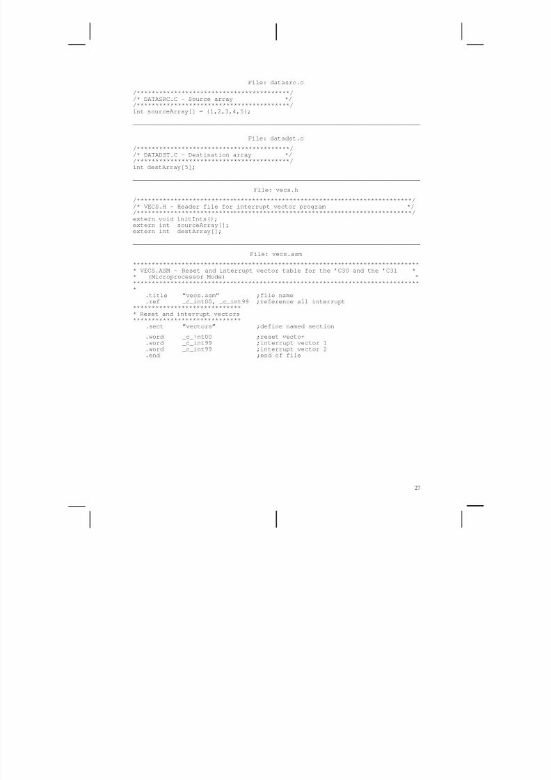
File: datasrc.c
/*****************************************//* DATASRC.C – Source array */
/*****************************************/int sourceArray[] = {1,2,3,4,5};
___________________________________________________________________________________
File: datadst.c
/*****************************************//* DATADST.C – Destination array *//*****************************************/int destArray[5];
___________________________________________________________________________________
File: vecs.h
/**************************************************************************//* VECS.H – Header file for interrupt vector program *//**************************************************************************/extern void initInts();extern int sourceArray[];extern int destArray[];
___________________________________________________________________________________
File: vecs.asm
****************************************************************************** VECS.ASM – Reset and interrupt vector table for the ’C30 and the ’C31 ** (Microprocessor Mode) *******************************************************************************
.title ”vecs.asm” ;file name
.ref _c_int00, _c_int99 ;reference all interrupt*****************************
* Reset and interrupt vectors*****************************.sect ”vectors” ;define named section
.word _c_int00 ;reset vector
.word _c_int99 ;interrupt vector 1
.word _c_int99 ;interrupt vector 2
.end ;end of file
5/17/2018 Setting Up Interupts in C - slidepdf.com
http://slidepdf.com/reader/full/setting-up-interupts-in-c 35/45
28
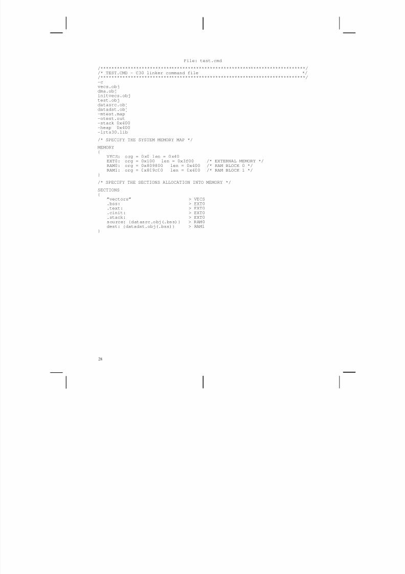
File: test.cmd
/***************************************************************************//* TEST.CMD – C30 linker command file */
/***************************************************************************/–cvecs.objdma.objinitvecs.objtest.objdatasrc.objdatadst.obj–mtest.map–otest.out–stack 0x400–heap 0x400–lrts30.lib
/* SPECIFY THE SYSTEM MEMORY MAP */
MEMORY{
VECS: org = 0x0 len = 0x40EXT0: org = 0x100 len = 0x3f00 /* EXTERNAL MEMORY */RAM0: org = 0x809800 len = 0x400 /* RAM BLOCK 0 */RAM1: org = 0x809c00 len = 0x400 /* RAM BLOCK 1 */
}
/* SPECIFY THE SECTIONS ALLOCATION INTO MEMORY */
SECTIONS{
”vectors” > VECS.bss: > EXT0.text: > EXT0.cinit: > EXT0.stack: > EXT0source: {datasrc.obj(.bss)} > RAM0dest: {datadst.obj(.bss)} > RAM1
}

5/17/2018 Setting Up Interupts in C - slidepdf.com
http://slidepdf.com/reader/full/setting-up-interupts-in-c 36/45
29
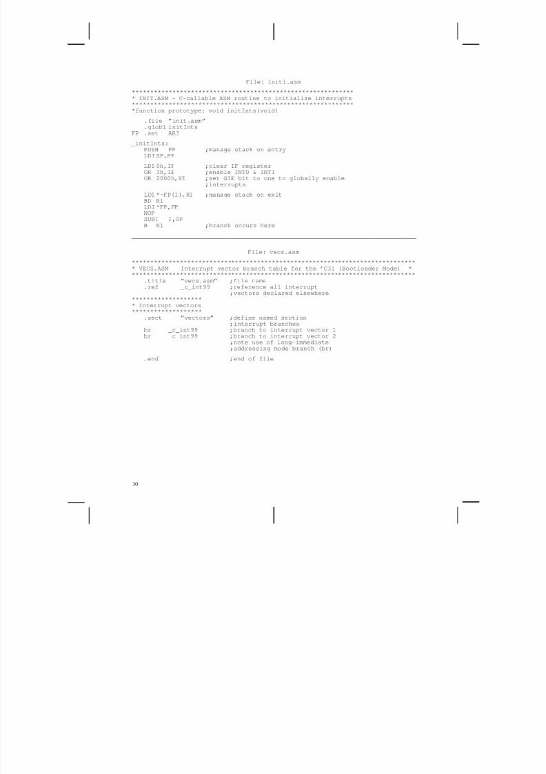
TMS320C31 Example
The following TMS320C31 example uses an assembly language named section to build the
interrupt-vector table and a C-callable assembly language module to set up the interrupt registers.However, no parameters are passed to this routine.
File: test.c
/**************************************************************************//* TEST.C – Test program *//**************************************************************************/#include ”vecs.h”
/**************************************************************************//* MAIN – Main routine *//**************************************************************************/void main(void){
initInts(); /* Enable interrupts */
for(;;); /* Replace with real code */
}
___________________________________________________________________________________
File: initvecs.c
/**************************************************************************//* INITVECS.C – Interrupt vector routines *//**************************************************************************/
/**************************************************************************//* C_INT99 – Interrupt service routine *//**************************************************************************/#define dummyISR c_int99 /* Rename ISR to correspond to TI */
/* naming conventions */void dummyISR(void){
for(;;); /* Replace with real ISR */}
___________________________________________________________________________________
File: vecs.h
/**************************************************************************//* VECS.H – Header file for interrupt vector program *//**************************************************************************/extern void initInts();
5/17/2018 Setting Up Interupts in C - slidepdf.com
http://slidepdf.com/reader/full/setting-up-interupts-in-c 37/45
30
File: initi.asm
************************************************************* INIT.ASM – C-callable ASM routine to initialize interrupts
*************************************************************function prototype: void initInts(void)
.file ”init.asm”
.globl initIntsFP .set AR3
_initInts:PUSH FP ;manage stack on entryLDISP,FP
LDI 0h,IF ;clear IF registerOR 3h,IE ;enable INT0 & INT1OR 2000h,ST ;set GIE bit to one to globally enable
;interrupts
LDI *–FP(1),R1 ;manage stack on exitBD R1
LDI*FP,FPNOPSUBI 2,SPB R1 ;branch occurs here
___________________________________________________________________________________
File: vecs.asm
****************************************************************************** VECS.ASM Interrupt vector branch table for the ’C31 (Bootloader Mode) ******************************************************************************
.title ”vecs.asm” ;file name
.ref _c_int99 ;reference all interrupt;vectors declared elsewhere
******************** Interrupt vectors
*******************.sect ”vectors” ;define named section;interrupt branches
br _c_int99 ;branch to interrupt vector 1br _c_int99 ;branch to interrupt vector 2
;note use of long-immediate;addressing mode branch (br)
.end ;end of file

5/17/2018 Setting Up Interupts in C - slidepdf.com
http://slidepdf.com/reader/full/setting-up-interupts-in-c 38/45
31
File: test.cmd
/***************************************************************************//* TEST.CMD – C31 linker command file */
/***************************************************************************/–cvecs.objinit.objinitvecs.objtest.obj–mtest.map–otest.out–stack 0x400–heap 0x400–lrts30.lib
/* SPECIFY THE SYSTEM MEMORY MAP */
MEMORY{
SRAM: org = 0x0 len = 0x100EXT0: org = 0x100 len = 0x3f00 /* EXTERNAL MEMORY */RAM0: org = 0x809800 len = 0x400 /* RAM BLOCK 0 */RAM1: org = 0x809c00 len = 0x3C1 /* RAM BLOCK 1 – 63 words */VECS: org = 0x809FC1 len = 0x3f
}
/* SPECIFY THE SECTIONS ALLOCATION INTO MEMORY */
SECTIONS{
”vectors” > VECS.text: > EXT0, block 0x10000.bss: > EXT0.cinit: > EXT0.const: > EXT0.stack: > EXT0.sysmem: > EXT0
}

5/17/2018 Setting Up Interupts in C - slidepdf.com
http://slidepdf.com/reader/full/setting-up-interupts-in-c 39/45
32
TMS320C40 Example With the PRTS
The following TMS320C4x example uses the parallel runtime-support (PRTS) library to set up the
interrupt vectors and initialize the interrupt registers. When using the PRTS library, the vector map is
created at run time using the install_int_vector() function. The user selects the location of the vector map
by placing the predefined named section .vector through the linker command file. The IVTP register is
initialized using the set_ivtp() function with the argument DEFAULT.
File: test.c
/**************************************************************************//* TEST.C – Test program *//**************************************************************************/#include ”vecs.h”
/**************************************************************************//* MAIN – Main routine *//**************************************************************************/void main(void){
initInts(); /* Initialize interrupt environment */
for(;;);}
___________________________________________________________________________________
File: initvecs.c
/**************************************************************************//* INITVECS.C – Interrupt vector routines *//**************************************************************************/#include ”vecs.h”
/**************************************************************************//* initInts() – Initialize processor interrupt registers *//**************************************************************************/void initInts(void){
set_ivtp(DEFAULT); /* Set IVTP */asm(”\t LDI \t 0h,IIF”); /* Clear the IIF reg */set_iie(TIMER0); /* Enable Timer0 int */install_int_vector((void *) c_int99, 2); /* Install timer interrupt */asm(”\t OR \t 2000h,ST”); /* Enable GIE bit */
}
/**************************************************************************//* C_INT99 – Interrupt service routine *//**************************************************************************/#define dummyISR c_int99 /* Rename ISR to correspond to TI */
/* naming conventions */void dummyISR(void){
for(;;); /* Replace with real ISR */}
___________________________________________________________________________________
File: vecs.h
/**************************************************************************//* VECS.H – Header file for interrupt vector program *//**************************************************************************/
#include <intpt40.h>#include <timer40.h>void c_int99(void);

5/17/2018 Setting Up Interupts in C - slidepdf.com
http://slidepdf.com/reader/full/setting-up-interupts-in-c 40/45
33
File: test.cmd
/***************************************************************************//* TEST.CMD – C40 linker command file */
/***************************************************************************/–ctest.objinitvecs.obj–mtest.map–otest.out–stack 0x400–heap 0x400–lprts40.lib–lrts40.lib
/* SPECIFY THE SYSTEM MEMORY MAP */
MEMORY{
VECS: org = 0x000000 len = 0x40RAM0: org = 0x2FF800 len = 0x400 /* RAM BLOCK 0 */RAM1: org = 0x2FFC00 len = 0x400 /* RAM BLOCK 1 */LOCAL: org = 0x300000 len = 0x7D00000 /* LOCAL BUS */GLOBAL: org = 0x8000000 len = 0x8000000 /* GLOBAL BUS */
}
/* SPECIFY THE SECTIONS ALLOCATION INTO MEMORY */
SECTIONS{
”.vector” > RAM0.bss: > LOCAL, block 0x10000.const: > LOCAL.text: > LOCAL.cinit: > LOCAL.stack: > LOCAL.sysmem: > RAM1
}
5/17/2018 Setting Up Interupts in C - slidepdf.com
http://slidepdf.com/reader/full/setting-up-interupts-in-c 41/45
34
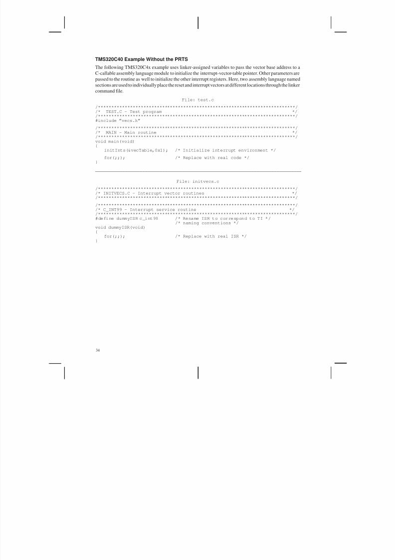
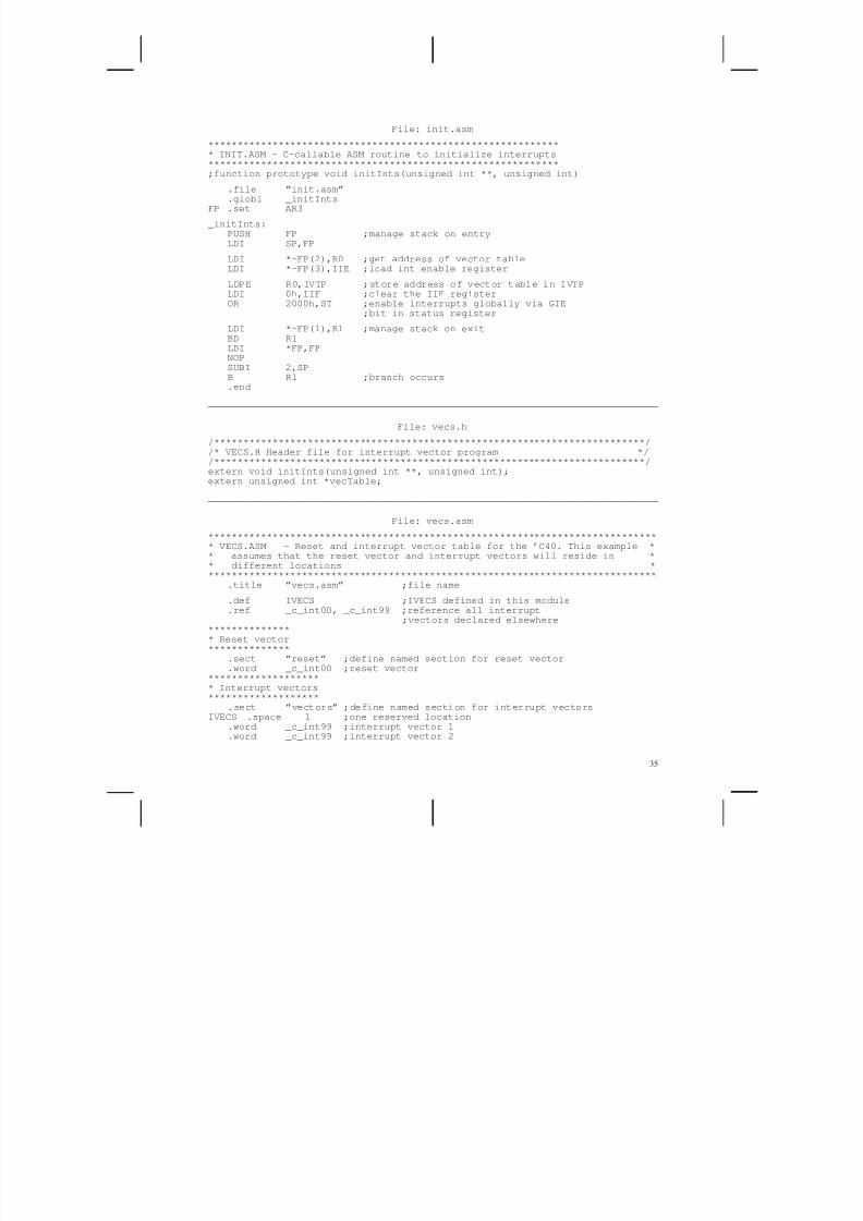
TMS320C40 Example Without the PRTS
The following TMS320C4x example uses linker-assigned variables to pass the vector base address to a
C-callable assembly language module to initialize the interrupt-vector-table pointer. Other parameters arepassed to the routine as well to initialize the other interrupt registers. Here, two assembly language named
sections are used to individually place the reset and interrupt vectors at different locations through the linker
command file.
File: test.c
/**************************************************************************//* TEST.C – Test program *//**************************************************************************/#include ”vecs.h”
/**************************************************************************//* MAIN – Main routine *//**************************************************************************/void main(void){
initInts(&vecTable,0x1); /* Initialize interrupt environment */
for(;;); /* Replace with real code */}
___________________________________________________________________________________
File: initvecs.c
/**************************************************************************//* INITVECS.C – Interrupt vector routines *//**************************************************************************/
/**************************************************************************//* C_INT99 – Interrupt service routine *//**************************************************************************/#define dummyISR c_int99 /* Rename ISR to correspond to TI */
/* naming conventions */
void dummyISR(void){
for(;;); /* Replace with real ISR */}
5/17/2018 Setting Up Interupts in C - slidepdf.com
http://slidepdf.com/reader/full/setting-up-interupts-in-c 42/45
35
File: init.asm
************************************************************* INIT.ASM – C-callable ASM routine to initialize interrupts
************************************************************;function prototype void initInts(unsigned int **, unsigned int)
.file ”init.asm”
.globl _initIntsFP .set AR3
_initInts:PUSH FP ;manage stack on entryLDI SP,FP
LDI *–FP(2),R0 ;get address of vector tableLDI *–FP(3),IIE ;load int enable register
LDPE R0,IVTP ;store address of vector table in IVTPLDI 0h,IIF ;clear the IIF registerOR 2000h,ST ;enable interrupts globally via GIE
;bit in status register
LDI *–FP(1),R1 ;manage stack on exitBD R1LDI *FP,FPNOPSUBI 2,SPB R1 ;branch occurs.end
___________________________________________________________________________________
File: vecs.h
/**************************************************************************//* VECS.H Header file for interrupt vector program *//**************************************************************************/extern void initInts(unsigned int **, unsigned int);extern unsigned int *vecTable;
___________________________________________________________________________________
File: vecs.asm
****************************************************************************** VECS.ASM – Reset and interrupt vector table for the ’C40. This example ** assumes that the reset vector and interrupt vectors will reside in ** different locations ******************************************************************************
.title ”vecs.asm” ;file name
.def IVECS ;IVECS defined in this module
.ref _c_int00, _c_int99 ;reference all interrupt;vectors declared elsewhere
*************** Reset vector**************
.sect ”reset” ;define named section for reset vector
.word _c_int00 ;reset vector******************** Interrupt vectors*******************
.sect ”vectors” ;define named section for interrupt vectorsIVECS .space 1 ;one reserved location
.word _c_int99 ;interrupt vector 1
.word _c_int99 ;interrupt vector 2

5/17/2018 Setting Up Interupts in C - slidepdf.com
http://slidepdf.com/reader/full/setting-up-interupts-in-c 43/45
36
File: test.cmd
/***************************************************************************//* TEST.CMD – C40 linker command file */
/***************************************************************************/–cinit.objinitvecs.objvecs.objtest.obj–mtest.map–otest.out–stack 0x400–heap 0x400–lrts40.lib
_vecTable = IVECS; /* Set vecTable to point to vector table */
/* SPECIFY THE SYSTEM MEMORY MAP */
MEMORY{
VECS: org = 0x000000 len = 0x40RAM0: org = 0x2FF800 len = 0x400 /* RAM BLOCK 0 */RAM1: org = 0x2FFC00 len = 0x400 /* RAM BLOCK 1 */LOCAL: org = 0x300000 len = 0x7D00000 /* LOCAL BUS */GLOBAL: org = 0x8000000 len = 0x8000000 /* GLOBAL BUS */
}
/* SPECIFY THE SECTIONS ALLOCATION INTO MEMORY */
SECTIONS{
”reset” > VECS”vectors” > RAM1.bss: > LOCAL, block 0x10000.text: > LOCAL.cinit: > LOCAL.const: > LOCAL.stack: > RAM0.sysmem: > LOCAL
}

5/17/2018 Setting Up Interupts in C - slidepdf.com
http://slidepdf.com/reader/full/setting-up-interupts-in-c 44/45
37
TMS320C50 Example
The following TMS320C5x example uses linker-assigned variables to pass the vector base address and
initial register values to a C routine. This routine loads the interrupt-vector-table pointer and other interrupt
registers using pointers to memory-mapped registers. Here, two assembly language named sections are
used to individually place the reset and interrupt vectors at different locations through the linker command
file.
File: test.c
/**************************************************************************//* TEST.C – Test program *//**************************************************************************/#include ”vecs.h”
/**************************************************************************//* MAIN – Main routine *//**************************************************************************/void main(void){
initInts(&vecTable,0x3); /* Enable interrupts INT0 and INT1 */
for(;;); /* Replace with real code */}
___________________________________________________________________________________
File: initvecs.c
/**************************************************************************//* INITVECS.C – Interrupt vector routines *//**************************************************************************/
/**************************************************************************//* initInts() – Initialize processor interrupt registers *//**************************************************************************/void initInts(unsigned int **vecTable, unsigned int imrValue){
unsigned int *imr = (unsigned int *) 0x04;/* IMR register */
unsigned int *ifr = (unsigned int *) 0x06;/* IFR register */unsigned int *pmst = (unsigned int *) 0x07; /* PMST register */*pmst |= (unsigned int) vecTable;*ifr = 0xffff; /* Clear IFR register */*imr |= imrValue; /* Load IMR register */asm(”\t CLRC\t INTM”); /* Clear interrupt mask bit */
}
/**************************************************************************//* C_INT3 – Interrupt service routine *//**************************************************************************/#define dummyISR c_int3 /* Rename ISR to correspond to TI */
/* naming conventions */void dummyISR(void){
for(;;); /* Replace with real ISR */}
___________________________________________________________________________________
File: vecs.h
/**************************************************************************//* VECS.H – Header file for interrupt vector program *//**************************************************************************/extern void initInts(unsigned int **, unsigned int);extern unsigned int *vecTable;
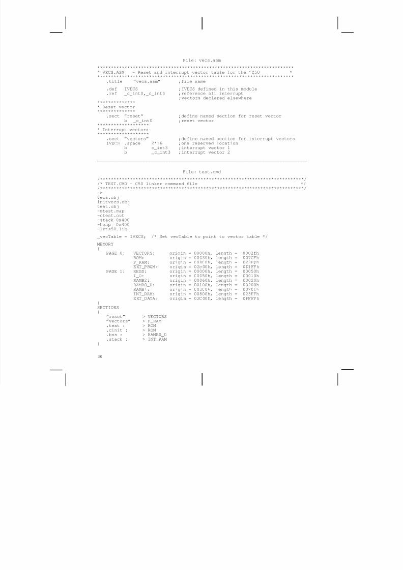
5/17/2018 Setting Up Interupts in C - slidepdf.com
http://slidepdf.com/reader/full/setting-up-interupts-in-c 45/45
38
File: vecs.asm
************************************************************************* VECS.ASM – Reset and interrupt vector table for the ’C50 *
************************************************************************.title ”vecs.asm” ;file name
.def IVECS ;IVECS defined in this module
.ref _c_int0,_c_int3 ;reference all interrupt;vectors declared elsewhere
*************** Reset vector**************
.sect ”reset” ;define named section for reset vectorb _c_int0 ;reset vector
******************** Interrupt vectors*******************
.sect ”vectors” ;define named section for interrupt vectorsIVECS .space 2*16 ;one reserved location
b c_int3 ;interrupt vector 1
b _c_int3 ;interrupt vector 2___________________________________________________________________________________
File: test.cmd
/***************************************************************************//* TEST.CMD – C50 linker command file *//***************************************************************************/–cvecs.objinitvecs.objtest.obj–mtest.map–otest.out–stack 0x400–heap 0x400
–lrts50.lib _vecTable = IVECS; /* Set vecTable to point to vector table */
MEMORY{
PAGE 0: VECTORS: origin = 00000h, length = 0002fhROM: origin = 00030h, length = 007CFhP_RAM: origin = 00800h, length = 023FFhEXT_PRGM: origin = 02c00h, length = 0D1FFh
PAGE 1: REGS: origin = 00000h, length = 00050hI_O: origin = 00050h, length = 00010hRAMB2: origin = 00060h, length = 00020hRAMB0_D: origin = 00100h, length = 00200hRAMB1: origin = 00300h, length = 00200hINT_RAM: origin = 00800h, length = 023FFhEXT_DATA: origin = 02C00h, length = 0FFFFh
}
SECTIONS{
”reset” > VECTORS”vectors” > P_RAM.text : > ROM.cinit : > ROM.bss : > RAMB0_D.stack : > INT_RAM
}