Sess ion B 5: FINITE ELEMENT METHOD (FEM) 285 · tensor and Ö å the creep strain tensor due to...
89
Session B5: FINITE ELEMENT METHOD (FEM) 285
Transcript of Sess ion B 5: FINITE ELEMENT METHOD (FEM) 285 · tensor and Ö å the creep strain tensor due to...

Session B5:
FINITE ELEMENT METHOD (FEM)
285

286

Comparison of mechanistic and phenomenological approaches to model drying shrinkage of concrete
Daniel Eriksson M.Sc., Ph.D. studentKTH Royal Institute of TechnologyDivision of Concrete StructuresSE-100 44 Stockholme-mail: [email protected]
Tobias Gasch Tech. Lic., Ph.D. student KTH Royal Institute of Technology Division of Concrete Structures SE-100 44 Stockholm e-mail: [email protected]
ABSTRACT Drying shrinkage of concrete is often estimated using a phenomenological approach where it is assumed that shrinkage is proportional to the change in internal humidity. In this study, a mechanistic approach was used which instead aims to mathematically describe the physical processes of drying shrinkage. Simulations of two laboratory tests were made and compared to results from two models based on the phenomenological approach. The results show that the developed model can describe drying shrinkage of concrete equally well as the phenomenological models but without the need to specify the final drying shrinkage strain.
Key words: Creep, Modelling, Shrinkage, Multiphase Porous Medium, Mechanistic Approach
1. INTRODUCTIONDrying shrinkage of concrete is often estimated by code-based relations such as those given inthe Eurocode 2 [1]; or by the use of another phenomenological approach where it is assumedthat drying shrinkage is proportional to the change in internal humidity. In the aforementionedmethods, the real physical processes of drying shrinkage are not considered. These physicalprocesses need to be accounted for explicitly in a real prediction of drying shrinkage. To thisend, a multiphase poromechanical model is used herein in which a mechanistic approach todrying shrinkage is adopted.
2 MEHCANISTIC APPROACH TO MODEL DRYING SHRINKAGE Due to the porous structure of concrete, a capillary pressure arises in the pore network as the material starts to dry. This pressure is in fact composed of several components, whose magnitude depends on the actual saturation level in the material. This has been widely discussed in the literature; see for example [2, 3]. The increasing capillary pressure during drying causes a decreasing pressure in the fluids (water and air) occupying the porous network, which in turn acts on the solid skeleton causing the shrinkage. The deformations of the solid phase can be described by the use of the effective stress principle [4]. In addition to the instantaneous deformation from the actual drying, it is also important to account for creep deformations of the
287

solid phase since the fluid pressures becomes rather high, [5]. The effect of creep deformations are of course more pronounced when studying early age concrete.
3 MATHEMATICAL MODEL To describe drying shrinkage of concrete according to the mechanistic approach, the concrete material is modelled as a deforming multiphase porous medium. The multiphase system is assumed to consist of the three phases: solid (s), liquid (w) and gas (g) where the gas phase is composed of the two species vapour (W) and dry air (D). The system of equations described below is implemented with the finite element method and solved using Comsol Multiphysics [6].
3.1 Governing equations The governing equations used in this study are derived based on the Thermodynamically Constrained Averaging Theory (TCAT), [7]. In total, there are ten governing equations in the mathematical model: three momentum balances in Eq. (1), four mass balances in Eq. (2) and three energy balances in Eq. (3).
∇ ⋅ (𝜀𝜀𝛼𝛼𝐭𝐭𝛼𝛼) = 0 (1)
𝜕𝜕(𝜀𝜀𝛼𝛼𝜌𝜌𝛼𝛼𝜔𝜔𝑖𝑖𝛼𝛼)𝜕𝜕𝜕𝜕
+ ∇ ∙ �𝜀𝜀𝛼𝛼𝜌𝜌𝛼𝛼𝜔𝜔𝑖𝑖𝛼𝛼𝐯𝐯𝛼𝛼� + ∇ ∙ �𝜀𝜀𝛼𝛼𝜌𝜌𝛼𝛼𝜔𝜔𝑖𝑖𝛼𝛼𝐮𝐮𝑖𝑖𝛼𝛼� + ∑𝑀𝑀𝑖𝑖𝛼𝛼→𝑖𝑖𝑖𝑖 = 0 (2)
𝜀𝜀𝛼𝛼𝜌𝜌𝛼𝛼𝐶𝐶𝑝𝑝𝛼𝛼𝜕𝜕𝜕𝜕𝜕𝜕𝜕𝜕
+ 𝜀𝜀𝛼𝛼𝜌𝜌𝛼𝛼𝐶𝐶𝑝𝑝𝛼𝛼𝐯𝐯𝛼𝛼 ∙ ∇𝑇𝑇 − ∇ ∙ (𝜀𝜀𝛼𝛼𝜆𝜆𝛼𝛼𝛻𝛻𝑇𝑇) = ∑𝑀𝑀𝑖𝑖→𝛼𝛼 (3)
In Eqs. (1-3), 𝛼𝛼 is the phase (s,w,g), 𝑖𝑖 the species (W, D), 𝜀𝜀 the volume fraction, 𝜌𝜌 the intrinsic density, 𝐭𝐭 the stress tensor, 𝜔𝜔 the mass fraction, 𝐯𝐯 the velocity, 𝐮𝐮 the diffusive velocity, 𝑀𝑀 a source term, 𝐶𝐶𝑝𝑝 the specific heat capacity, 𝑇𝑇 the temperature and 𝜆𝜆 the thermal conductivity. It should be noted that the governing equations (1) and (3) are summed over all three phases, resulting in one balance equation for momentum and energy, respectively. Concerning the mass balances, the liquid phase (w) and vapour species (Wg) are summed into one balance equation. In summary, this results in five governing equations. Capillary pressure, gas pressure, deformations and temperature are chosen as dependent variables in the system of equations.
3.2 Boundary conditions The governing equations must be complemented with appropriate boundary conditions. Concerning the mechanical part, i.e. Eq. (1), prescribed displacements are used while moisture and temperature fluxes of convective type are used for Eqs. (2-3).
3.3 Constitutive relations In order to close the system of governing equations, they must be complemented with a number of constitutive relations, defined similarly to [5]. The mechanical behaviour of the solid skeleton is modelled using a linear elastic material model. However, a creep model based on the Microprestress-Solidification theory is also used on a similar form as in [8]. The mechanical constitutive relation is defined as
𝐭𝐭 = 𝔻𝔻: (𝐞𝐞 − 𝐞𝐞𝜕𝜕ℎ − 𝐞𝐞𝑐𝑐𝑐𝑐) − 𝑏𝑏𝑝𝑝𝑠𝑠𝐈𝐈 (4)
In Eq. (4), 𝔻𝔻 is the elastic stiffness tensor, 𝐞𝐞 the elastic strain tensor, 𝐞𝐞𝜕𝜕ℎ the thermal strain tensor, 𝑏𝑏 Biot’s coefficient, 𝑝𝑝𝑠𝑠 the pressure on the solid skeleton exerted by the fluids, 𝐈𝐈 a unit
288

tensor and 𝐞𝐞𝑐𝑐𝑐𝑐 the creep strain tensor due to the pressure on the solid skeleton from the fluid phases and is calculated with the implemented creep model. Creep strains are here calculated using the effective stress, hence the pressure 𝑝𝑝𝑠𝑠 also enters the creep model causing additional deformations [2].
4 COMPARISON OF SHRINKAGE MODELLING The mechanistic approach to model drying shrinkage of concrete adopted here is compared to laboratory results by Bryant and Vadhanavikkit [9], as well as with results from two different phenomenological approaches applied to the same laboratory test. The first model is the drying shrinkage model given in the Eurocode 2 [1], but with the final drying shrinkage strain set equal to the final strain observed in the tests. The second is a model by Gasch [8] which used a diffusion type mass transfer model under the phenomenological assumption that the shrinkage strains are proportional to changes in internal humidity. It is, therefore, necessary to know the final shrinkage strain in beforehand. In addition, the model also included a damage model and the same creep model as implemented here, but only considered the total stress to cause creep deformations. Since the same creep model was used, the same input parameters are also used in the simulations with the mechanistic approach.
4.1 Laboratory test The laboratory tests by Bryant and Vadhanavikkit [9] included a large program of testing but only two of the performed tests are considered in this comparison. These two tests were performed on prismatic concrete specimens with a dimension of 4L×L×L with L=100 mm and L=150 mm. The specimens were subjected to the ambient air on two sides, which had a relative humidity of 60 % and a temperature of 20 oC. The water cement ratio of the concrete was 0.47, with an elastic modulus of 28.1 GPa and a compressive strength of 50.1 MPa at an age of 28 days. The drying of the specimens started after 8 days of moisture curing.
4.2 Comparison of results The results from the simulations are shown in Fig. 1 together with the results from the laboratory tests and the two discussed phenomenological models.
Figure 1 – Comparison of shrinkage strains. Left: L=100 mm. Right: L=150 mm.
As can be seen, all models capture the shape of the shrinkage strains over time. However, it can also be observed that the predicted strain from the Eurocode 2 model develops too slowly, i.e. the predicted drying time of the specimen is underestimated. The other two models comply with the laboratory test results. One thing that should be emphasized is that the final drying shrinkage strain must be specified in the phenomenological model used in [8], since it assumes that the shrinkage strains are proportional to the change in internal humidity. The mechanistic model, on
289

the other hand, does not require the final drying shrinkage strain as an input. The strains are instead calculated based on the physical processes described by the model. By studying the results in Fig. 1, it is evident that the model can capture the drying behaviour of concrete. Even though the model describes the physical processes related to shrinkage, it still relies on some assumptions and simplifications in its constitutive relations. These include some parameters that are hard to determine directly in laboratory tests and must be calibrated. This is something that is common to all type of models and it is important that the calibrated parameters are within reasonable ranges. Still, mechanistic models aims to describe the physical processes and Pesavento et al. [5] therefore argue that they are more accurate when extrapolating calibrated models to other applications and scales compared to phenomenological models. It should also be mentioned that a concrete degradation model ought to be implemented for drying simulations of larger specimens. This is due to that larger moisture gradients can be expected at the surface, resulting in micro cracks which soften the material and reduces the observed shrinkage.
6 CONCLUSIONS Concrete was modelled as a deforming multiphase porous medium where drying shrinkage was included using a mechanistic approach. Simulations of two laboratory tests were made and compared to results from two other models where the drying shrinkage was described by a phenomenological approach. The results show that it is possible to simulate drying shrinkage of concrete by mathematically describing the physical processes of drying shrinkage instead of relying on the assumption that shrinkage is proportional to the change in internal humidity. This also means that it is not necessary to specify the final drying shrinkage strain in the model.
ACKNOWLEDGEMENT The research presented was carried out as a part of “Swedish Hydropower Centre -SVC”. SVC has been established by the Swedish Energy Agency, Energiforsk and Svenska Kraftnät together with Luleå University of Technology, KTH Royal Institute of Technology, Chalmers University of Technology and Uppsala University. www.svc.nu.
REFERENCES
[1] EN 1992-1-1:2005: “Eurocode 2: Design of concrete structures – Part 1-1: General rulesand rules for buildings”, The Swedish Standards Institute (2008)
[2] Gawin D., Pesavento, F., Schrefler, B.A.: “Modelling creep and shrinkage of concrete bymeans of effective stresses”, Materials and Structures, vol. 40, pp. 579-591 (2007)
[3] Gray W.G., Schrefler, B.A.: “Thermodynamic approach to effective stress in partiallysaturated porous media”, Eur J Mech A Solids, vol. 20, pp. 521-538 (2001)
[4] Gray, W.G., Schrefler, B.A., Pesavento, F.: “The solid phase stress tensor in porous mediamechanics and the Hill-Mandel condition”, J Mech Phys Solids, vol. 50, pp. 539-554(2009).
[5] Pesavento, F., Screfler B.A., Sciumè, G.: “Multiphase flow in deforming porous media: Areview”, Arch Computat Methods Eng, pp. 1-29 (2016)
[6] “Comsol Multiphysics ver 5.2a Documentation”, Comsol AB, Stockholm, Sweden (2016)[7] Gray. W.G., Miller, C.T.: “Introduction to the thermodynamically constrained averaging
theory for porous medium systems”, Advances in geophysical and environmentalmechanics and mathematics, Springer (2014)
[8] Gasch, T.: “Concrete as a multi-physical material with applications to hydro powerfacilities”, Licentiate Thesis, Royal Institute of Technology, (2016)
[9] Bryant, A.H., Vadhanavikkit, C.: ”Creep, shrinkage-size, and age at loading effects”, ACIMaterials Journal, Vol. 84, pp. 117-123 (1987)
290

1
Evaluating the seismic behavior of reinforced concrete piers of bridges by using fibre plastic hinge elements
Mohammad Hajmohammadian Baghban M.Sc., Ph.D., associate professorDepartment of Manufacturing and Civil Engineering, Faculty ofEngineering, NTNU – Norwegian University of Science andTechnology, Gjøvik , NorwayEmail: [email protected]
Saeid Gerivani M.Sc., StudentDepartment of Civil Engineering, Faculty of Engineering, BandarAbbas Branch, Islamic Azad University, Bandar Abbas, IranEmail: [email protected]
ABSTRACT Concrete is widely used for bridge construction. Defining fibre elements in the finite element simulation process can give detailed properties of reinforced concrete elements and lead to improving the accuracy of the results. In this study, the behavior of concrete piers is discussed by using nonlinear static analysis under the effect of constant load pattern with definition of fibre plastic hinges. Defining nonlinear materials and plastic hinges results in more accuracy in stiffness distribution. Consequently, the shear capacity of the concrete piers is reduced by uneven stiffness distribution.
Keywords: Structural Design, Reinforcement, Modelling, Bridge, Fibre Hinge, Pushover Analysis
1. INTRODUCTIONDifferent factors such as versatility, aesthetic appearance and economic issues have led to morecommonly use of concrete bridges compared to other types of materials. The possibility ofbuilding concrete bridges in long-spans or building in different forms such as single pier at eachsupport make the bridges cost-effective and scenic [1,2].Bridges are usually used as flyovers or natural cut crosses and they play a vital role incommunication and everyday life. As one of the main elements of road transport, studying theseismic behavior of these structures under the effect of earthquake is essential. When anearthquake occurs, bridges play a unique role in linking roads and highways to send aid.Concerning bridges with reinforced concrete piers, the shear capacity of the piers is one of thecrusial factors in structural design, especially under seismic loads. Therefore, properunderstanding of the behaviour of these elements is of great importance. In order to achieve
291

2
appropriate accuracy, fibre plastic hinges can be defined in cross-sectional area. Using this definition, the relation between the biaxial moment and axial force, and distribution of non-linear behavior of the section is evaluated by particular stress-strain relationship in every fibre element. In this study the seismic behavior of reinforced concrete bridge piers are studied by defining fibre section features under nonlinear static analysis method [2,3].
2. INVESTIGATED BRIDGESNine reinforced concrete bridges are considered for the parametric study. This set includes bothshort and long bridges with 180 m and 280 m length, with pier height ratios of 1, 1.5, 2, 2.5 and3, corresponding to a height of 7.5, 11.25, 15, 18.75 and 22.5 meters, respectively. The spans inshort bridges are 40, 50, 50 and 40 meters and the spans in long bridges are 40, 50, 50, 50, 50and 40 meters, respectively. These bridges are designed by Alvarez [4,5], at European Schoolfor Advanced Studies in Reduction of Seismic Risk by using displacement-based designmethod.
2.1 Bridge specifications Material properties and some characteristics of the bridges are introduced in tables 1 and 2.
Table 1– Materials properties. Table 2– Some characteristics of considered bridges. Steel rebar
fy Mpa 455 Yield stress EsMpa 200000 Modulus of
elasticity dbl mm 43 Diameter of
longitudinal rebar
Concrete fc
'Mpa 40 Compressive strength
EcMpa 30000 Modulus of elasticity
Wc KN/m3 25 Unit Weight
Bridges group All bridges Type Regula/ irregular pier diameter (m) 2 Number of longitudinal rebar
74
The percent of longitudinal rebar
3.42%
2.2 Bridge deck The design process of the deck is based on avoiding non-linear behavior, so the response will be elastic. The deck dimensions are based on positioning two crossing lanes. A cross-section of the bridge is shown in Figure 1. The moment of inertia of the deck is Im = 45m4 and the torsional moment of inertia has been neglected [5].
Figure 1– Cross section of the bridge [5]. 2.3 Abutments The equivalent linear springs are commonly used to show the deck constraints by abutment. In this study the spring stiffness is KA = 75000 kN/m [5].
292

3
2.4 Fibre plastic hinges By using finite fibre elements, it is possible to define reinforced concrete material properties more detailed and increase the accuracy of the results. By defining fibre hinge, it is possible to calculate the moment-curvature relationship in bending directions for different levels of axial loads during the nonlinear static analysis. The sriffness reduction due to concrete cracking, yielding in rebar and strain hardening can be applied to the fibre model. Sufficient number of fibre elements should be considered to achieve adequate accuracy in the cross-sectional area. It is recommended that the section properties of the hinge such as area and moment of inertia would be within 5% of the gross section properties [6,7]. Some specifications of the fibre elements are presented in Fig. 2. Priestley-Park equation was used to calculate the length of plastic hinge, which is a popular model for reinforced concrete piers [8]:
dfLL yp 022.008.0 += (1) Where Lp is effective length of the plastic hinge, L is the pier height, fy is yield stress of the reinforcement and d is diameter of the reinforcement.
Table 3– Fibre section properties
Figure 2 – Fibre hinge [9]
3. ANALYSIS METHODNonlinear static analysis method under the effect of constant load pattern in transverse directionis used in this study. Pushover analysis obtains the response of the structure under lateral loadpattern with monotonical increase.The main product of this process is the diagram of base shear changes against the displacementof the control point, which is called structural capacity curve. Each point on the curve indicatesa special type of structural damage. The entire process of cracking, plastic hinge formation andfailure of structural components can be observed in the process [2].
4. RESULTSThe results are shown for two groups of short and long bridges in Fig. 3. The short bridge groupwith regular stiffness distribution have higher shear capacity compared to bridges withirrigularity. This indicates the higher strength of regular structures under applied loads. The
Main Section
Fiber
2 Pier diameter (m) 300 number of fibre elements
1.4417 1.4895 Area (square meter) 0.2033 0.2441 Moment of inertia 33
(m4) 0.2033 0.2441 Moment of inertia 22
(m4) 0.04 Difference in area
(percent) 0.02 Difference in moment of
inertia 33(Percent) 0.02 Difference in moment of
inertia 22(Percent)
293

4
capacity is reduced by increase in irregularity of stiffness distribution where the bridge 133 gives the highest irregularity and the lowest shear capacity. Furtheremore as illustrated in pushover analysis curves on the right side of Fig 3, the shear capacities of the reinforced concrete piers in long bridges are also reduced when the irregularity of stiffness distribution is increased. The bridge with caption 1،1.5،2،2.5،3 had the lowet shear capacity in this group.
Figure 3 – Pushover analysis in transverse direction for short bridges (Left) and long bridges (Right), the curve numbers indicate the pier height ratios of the bridges as described in part 2.
Since there is a direct relationship between stiffness distribution and shear capacity, defining non-linear materials and fibre plastic hinges for the cross sections of reinforces concrete piers of bridges gives more accurate results.
REFERENCES
[1] Hosseini, M.: “The basic topics of concrete bridges”, Publication of Ferdowsi University,Mashhad (1992)
[2] Gerivani, S.: “Assessment and Comparison of Nonlinear Static Analysis Methods toDetermine the Capacity of Irrigular Bridges”, Master's thesis, Faculty of CivilEngineering, Islamic Azad University of Bandar Abbas (2016)
[3] Nicknam, A., Mosleh, A., Hamidi Jamnani, H.: “ Seismic Performance Evaluation ofUrban Bridge using Static Nonlinear Procedure, Case Study: Hafez Bridge”, The TwelfthEast Asia-Pacific Conference on Structural Engineering and Construction (2011)
[4] Alvarez, J,C,B.,: “Displacment-Based Design of Continuous Concrete Bridge UnderTransverse Seismic Excitation”, European School for Advanced Studies in Reduction ofSeismic Risk, Rose School (2004)
[5] Restrepo, J, C, O.: “Displacment-Based Design of Continuous Concrete Bridge UnderTransverse Seismic Excitation”, European School for Advanced Studies in Reduction ofSeismic Risk, Rose School (2007)
[6] Monteiro,R, N, C.: “Probabilistic Seismic Assessment of Bridges”, Civil Engineering,Faculty of Engineering, Universidade Porto (2011)
[7] Aviram, A., Mackie, K., Stojadinovic, B.: “Guidelines for Nonlinear analysis of BridgeStructures in California”, Techincal Report, Pacific Earthquake Engineering ResearchCenter, University of California, Berkeley (2008)
[8] AI Q., WANG, D., LI, H., Sun, Z.: “Evaluation of Seismic Performance of ReinforcedConcrete Bridge Column Based on Plastic Hinge Modal”, The 14th World Conference onEarthquake Engineering, Beijing, China (2008)
[9] Eberhard, M,O, Berry, M,P, Modeling of Reinforced Concrete Bridge Columns, PEERAnnual Meeting, San Francisco,California (2006)
294

Analyses of concrete structures subjected to extreme loading
Håkan Hansson Tech. Lic., Lecturer KTH Royal Institute of Technology Division of Concrete Structures SE-100 44, STOCKHOLM, Sweden e-mail: [email protected]
ABSTRACT A recently developed numerical methodology is demonstrated for the analyses of concrete structures subjected to extreme loading and large deformations. This methodology combines a discrete particle formulation with non-linear finite element modelling to improve analyses of i.e. penetration phenomena. The penetration of a projectile into a concrete target is studied by the use of this numerical methodology. Experimental results for impacts of both reinforced and unreinforced concrete targets are used for comparisons with the simulation results, and the simulations show reasonable results for these two simulation cases.
Key words: Computational mechanics, Modelling, Protective structures, Reinforcement
1 INTRODUCTION Analyses of structures subjected to extreme loading, e.g. air-blast loadings, other explosive effects and projectile penetration also apply to e.g. civilian shelters and command centres for the rescue services. Furthermore, similar analyses may also be necessary for other buildings and infrastructure projects, with respect to the hazard of transportation of dangerous material, and also for risk assessment of specific buildings. The later incl. both accidental explosions, e.g. gas explosions, and terrorism threats. An appropriate design of a building or protective structure should reduce the consequences due to explosions, as well as from e.g. earthquakes and impacting projectiles, vehicles and airplanes. The design of a structure subjected to extreme loading needs to consider both local and structural load effects. The impact of projectiles or fragments, or detonations of high explosives near the structure causes mainly a concentrated local damage to the structure with crushing and failure, which is more difficult to predict than the global response of the structure. The aim for the research is to establish improved analyses methodology for protective structures subjected to extreme loading conditions. The use of improved analyses may be one tool necessary for the development of better optimized protective structures and new design solutions in the future. An improved numerical methodology for analyses of concrete structures subjected to extreme loading is under development in cooperation with IMPETUS Afea AS, Norway (www.impetus-afea.com). This paper focuses on this improved methodology for analyses of the local effects of projectile penetration, without further analyses of the structural effects. According to the general definition a projectile may be any type of flying object impacting the structure. However, this initial study primary concerns the design of protective structures impacted by penetrating warheads.
295

2 BENCHMARK PENETRATION EXPERIMENTS A series of model scale tests were earlier performed at FOI [1], these tests were financed by the Swedish Armed Forces. The tests were performed since in many cases published penetration experiments were lacking essential data necessary for an accurate finite element (FE) analysis, e.g. material specifications, material properties and impact conditions. The test series wastherefore designed to identify possibilities and limitations regarding later FE analyses ofpenetration in protective structures. The concrete targets were either unreinforced cylindricalconcrete targets, with diameters 1.2 and 1.5 m, or reinforced concrete targets with a 1.2×1.2 mcross section. Normal strength concrete with a compressive mean strength of approximate50 MPa was used for the main part of tests [1]. The reinforcement was ∅14 mm B500BT steel,with c/c 60 mm and placed in five layers in two directions. Furthermore, interconnecting rebarswith c/c 180 mm were also used between the layers. Two of the test cases are here used todemonstrate the newly developed numerical methodology for penetration modelling. These werereinforced and unreinforced concrete targets with 0.60 m thickness, with impact velocities424 m/s and 425 m/s, respectively. The targets are shown in Fig. 1.
Figure 1 – Post-test photos of front and back faces of target from tests no. 2004-6 (upper row) and no. 2004-20 (lower row) [1,2]. The left figures show the front face of the targets.
Practical considerations limited the diameter of the used projectile to 50 mm, and the projectile mass to approximate 4.50 kg, in comparison an air bomb normally weights between 120 and 1000 kg. The steel projectiles were filled with an inert material, density approximate 1.6×10³ kg/m³ to obtain the desired projectile weight. The experiments were performed with varying nose shape, impact velocities and impact angles. The main part of the tests was performed with the projectile nose design shown in Fig. 2, and this projectile design was also used for the test cases simulated here.
296

Figure 2 – Model projectile with 50 mm diameter, 450 mm length and 400 mm ogive radius [1,2]. Definition of the nose section radius is shown to the right.
3 PENETRATION MODELLING METHODOLOGY The use of finite element models for the analyses of non-linear behaviour of structures requires a good knowledge of both the material’s behaviour and a suitable numerical approach for the specified problem. Both of these are challenging areas within the field of penetration mechanics. Earlier FE analysis studies of penetration in concrete are e.g. [2-7]. A combined particle-element method was earlier developed for the EPIC (Elastic Plastic Impact Computations) code [8]. However, the original integration points for the elements are here converted to massless stress points, and the mass retained at the original nodes for the elements. The methodology used here instead uses a packing of particles of any desired size to be used at the original location of the deformed elements.
3.1 Model set up The tests analysed here were earlier analysed with a different numerical methodology [2], and several limitations of the used numerical methodology were then identified. Therefore, the IMPETUS Afea solver release version 1868 (www.impetus-afea.com), with the newly developed methodology for non-linear finite element analyses of concrete structures subjected to extreme loading, e.g. projectile penetration, is used here. Heavily deformed solid elements that occur during a penetration analyses are removed, and the elements are replaced with discrete particles during the simulation. Initially the HJC (Holmquist-Johnson-Cook) material model [3] with a compressive strength set to 50 MPa is used for the concrete in the modelling, and the JC (Johnson-Cook) material model [9] for the steel casing of the projectile. In this case material properties for tool steel S-7 are assumed, with yield strength equal to 1539 MPa. A representative average strength for the rebars is assumed to be 550 MPa, with truss elements that are fully coupled to the concrete used for the reinforcement. Two of the earlier analysed penetration tests were chosen to demonstrate this new modelling concept. Approximate 40 mm of the nose of the projectile is modelled with an elastic material model, this is to avoid localized failure near the penetrators front end.
3.2 FE analyses results These initial FE simulations with nominal input data resulted in an exit velocity of 132 m/s for the unreinforced target, and a penetration depth of 0.58 m for the reinforced target. The corresponding exit velocity for the unreinforced test was 139 m/s, and the experimentally determined penetration depth for the reinforced target was 0.53 m. The two models are shown in Fig. 3. The heavily distorted elements that occurred during the simulations are here replaced by approximate 400,000 discrete particles, with 2 mm diameter, in both models.
4 DISCUSSION AND FUTURE RESEARCH These preliminary FE analyses show promising results for the new modelling approach, with a fair agreement with the experimental results. This new modelling approach, with the use of a particle formulation, can avoid problems related heavily distorted elements that may influence the simulation results. However, the interaction between particles and solid elements needs to be further improved, with the current implementation causing unphysical energy errors due to local
297

instabilities for the particles. Furthermore, an advanced concrete model, with e.g. better tensile failure conditions, should be evaluated when this numerical methodology is established.
Figure 3 – Calculated damage of the unreinforced target to the left is shown 4 ms after impact, with the reinforced target to the right shown at final stage.
REFERENCES
[1] Hansson, H.: “Penetration in concrete for projectiles with L/D≈9”, FOI-R--1659--SE, FOI,Tumba (2005)
[2] Hansson, H., Malm, R.: “Non-linear finite element analysis of deep penetration inunreinforced and reinforced concrete”, Nordic Concrete Research, Vol. 44, pp. 87-107(2011)
[3] Holmquist, T.J., Johnson, G.R., Cook, W.H.: “A computational constitutive model forconcrete subjected to large strains, high strain rates and high pressures”, Proceedings of14th International Symposium on Ballistics, Quebec City, pp. 591-600 (1993)
[4] Tham, C. Y.: “Numerical and empirical approach in predicting the penetration of aconcrete target by an ogive-nosed projectile”, Finite Elements in Analysis and Design,Vol. 42, No. 14-15, pp. 1258-1268 (2006)
[5] Cullis, I., Hinton, M., Gilbert, S., Church, P., Porter, D., Andrews, T. Proud, W., Pullen,A.: “Towards predictive modelling for concrete”, International Journal of ImpactEngineering, Vol 35, No. 12, 1478-1483 (2008)
[6] Polanco-Loria, M., Hopperstad, O.S., Børvik, T., Berstad, T.: “Numerical predictions ofballistic limits for concrete slabs using a modified version of the HJC concrete model,International Journal of Impact Engineering”, Vol. 35, No. 5, pp. 290-303 (2008)
[7] Liu, Y., Ma, A. and Huang, F.: “Numerical simulations of oblique-angle penetration bydeformable projectiles into concrete targets”, International Journal of Impact Engineering,Vol. 36, No. 3, 438–446 (2009)
[8] Johnson, G. R., Beissel, S. R., Gerlach, C. A.: “A combined particle-element method forhigh-velocity impact computations”, Procedia Engineering, Vol. 58, pp. 269-278 (2013)
[9] Johnson, G. R., Cook, W.H.: “A constitutive model and data for metals subjected to largestrains, high strain rates, and high temperatures,” Proceedings, 7th InternationalSymposium on Ballistics, The Hague, pp. 541-547 (1983)
298

Stability assessment of concrete dams with non-linear FEA
Rikard Hellgren M.Sc.KTH Royal Institute of TechnologyBrinellvägen 23, SE-100 44 Stockholm, Swedene-mail: [email protected]
Richard Malm Ph.D. KTH Royal Institute of Technology Brinellvägen 23, SE-100 44 Stockholm, Sweden e-mail: [email protected]
ABSTRACT In dam safety assessments, it must be shown that concrete dams are safe against sliding and overturning failure modes. This is typically performed with analytical calculations based on force equilibrium of a rigid body. In more complex cases, these analyses are time-consuming and have to be based on assumptions regarding the dam’s behaviour or simplifications. By using non-linear finite element analyses (FEA), more detailed and realistic analyses can be performed where it is possible to include cracks, degradation, material strength, dam-rock interaction etc. A method to perform these analyses is presented, based on the same safety concept as for the classical methods.
Key words: Modelling, Structural Design, Structural behaviour
1. STABILITY ASSESSMENTSFor safety assessment of Swedish concrete dams, the Swedish power companies guidelines fordam safety, (RIDAS [1]), requires that dams are verified against overturning and sliding for allreasonable loads and load combinations. For overturning, the safety factor for the structure isdefined as the ratio between stabilizing moments and de-stabilizing moments.
𝑠𝑠𝑓𝑓𝑓𝑓 = 𝑀𝑀𝑠𝑠
𝑀𝑀𝑑𝑑(1)
where 𝑠𝑠𝑓𝑓𝑓𝑓 is the safety factor for overturning, 𝑀𝑀𝑠𝑠 is the sum of stabilizing moments and 𝑀𝑀𝑑𝑑 is the sum of de-stabilizing moments. The moments are usally calculated with the dam toe as the axis of rotation, but other assumptions occur where the axis is moved due to considerations regarding the strength of the structure and the foundation. For sliding, the safety factor is defined as the ratio between the maximum friction force in the interface between concrete and rock and the acting forces parallel to the sliding surface (i.e. often horizontal forces).
299
𝑠𝑠𝑓𝑓𝑠𝑠 = 𝜇𝜇𝑖𝑖𝑖𝑖𝑖𝑖 ∑𝑉𝑉∑𝐻𝐻
(2)
where, 𝜇𝜇𝑖𝑖𝑖𝑖𝑖𝑖 is the coefficient of friction in the interface, ∑𝐻𝐻 is the sum of all horizontal forces (i.e. parallel to the sliding plane) and ∑𝑉𝑉 are the sum of all vertical forces. A more common way of expressing the safety for sliding is to refer to the required friction angle 𝜇𝜇, defined as
𝜇𝜇 = ∑𝐻𝐻∑𝑉𝑉
(3)
The factor of safety should typically exceed 1.35 and 1.50 for sliding and overturning respectively for normal loads according to RIDAS. Based on the safety factor for sliding, a maximum allowed friction coefficient could alternatively be formulated as 1
1.35≈ 0.75, which is
used in practice in traditional stability analyses.
The traditional stability analyses are typically performed with hand calculation methods, based on force equilibrium of a rigid body. The analytical calculations require that force resultant and lever arm are calculated for all loads including self-weight. For simple dam geometries, this work is quite straightforward and trivial. However, many concrete dams consist of variable and non-trivial geometries. This is particularly true for spillways where stability calculations often are time-consuming with many potential error sources. In many cases this approach may be sufficient to assess the safety of the dam. However, the analytic hand calculation method is insufficient when non-linear effects must be considered. This is for example the case when the structure no longer can be considered to act monolithic (i.e. due to cracks that may result in internal failure modes, a strengthened structure) or when more complex dam-foundation interaction than an idealized Mohr-Coulomb friction is considered.
3. NUMERICAL FAILURE ANALYSESThere are two basic methods for simulating the failure of a structure, strength reduction andoverload. In the strength reduction method, normal loads are applied on the structure andthereafter are the material strength reduced until failure occurs. This method is common ingeotechnical applications where the external load is a small part of the total load. In the overloadmethod, normal loads are applied on the structure and these loads are thereafter increased until afailure occurs. This technique is generally applied in construction applications such as failureload estimations of bridges, buildings, nuclear power plants, etc.
3.1 Progressive failure analyses of concrete dams For concrete dams, the strength reduction method can be implemented on the friction coefficient in the dam-rock interface. In the first simulation step, the actual friction coefficient based on the friction angle is used and all design loads are applied. Thereafter the friction coefficient is continuously reduced until a failure occurs. This approach predefines a failure in the concrete-rock interface.
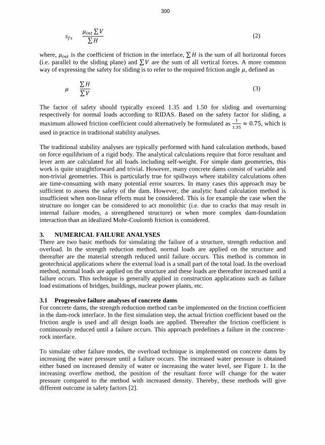
To simulate other failure modes, the overload technique is implemented on concrete dams by increasing the water pressure until a failure occurs. The increased water pressure is obtained either based on increased density of water or increasing the water level, see Figure 1. In the increasing overflow method, the position of the resultant force will change for the water pressure compared to the method with increased density. Thereby, these methods will give different outcome in safety factors [2].
300

Figure 1 – Illustration of the method of increased pressure numerical progressive failure analyses, from [2].
3.2 Overturning and sliding in progressive failure analyses The failure modes used in the analytical stability calculations are based on the assumption that the dam acts as a rigid body. The dam is, however, a deformable structure and the failure mode obtained in FE analyses is usually a combination of overturning and sliding. In FE analyses, the common failure progression starts as the upstream toe of the dam is lifted of the ground due to the overturning forces. This reduces the contact area between the dam and the foundation which implies that the total shear force must be mobilized over all smaller areas, resulting in too high shear forces compared to the normal forces and thereby causing a sliding failure. This combined failure mode results in a lower factor of safety compared to the traditional sliding failure. As RIDAS requires that the dam is verified against overturning and sliding, some modification can be applied on the rock-concrete interface to induce the requested failure mode [3]. When an overturning failure is wanted, the friction coefficient can be increased several magnitudes. This prevents any sliding displacements and as a consequence, the obtained failure mode is overturning. To obtain a sliding failure, a restrain that prohibits separation between the dam and rock is applied.
4. RESULTSThe difference in obtained safety factor was studied by [4] for the approaches; increased densityand increased water level methods. The two methods was compared for both an induced slidingfailure and an induced overturning failure. Furthermore, comparison was made betweenincreasing all densities and only increases the density on the destabilizing loads. The results areshown in Table 2. The results showed that for simulating a sliding failure both method gavereasonable results if only the destabilizing loads were increased. In case of an inclined upstreamsurface, only the horizontal component of the water pressure should be increased. However forsimulations of an overturning failure, it was found that the increased density approach with onlydestabilizing loads has to be used as the other methods overestimates the safety factor. Since thereal failure may be a combination of these two failure modes, this method should be used for allfailure simulations.
Using the increasing density method where only destabilizing loads are increased, the safety factor has been calculated for several cases as seen in Table 3. The results shows that for the studied dams the combined failure mode have lower safety factor than the individual failure modes.
301
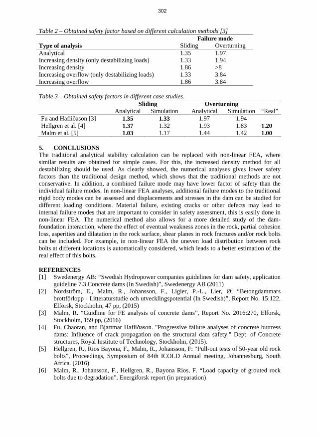
Table 2 – Obtained safety factor based on different calculation methods [3] Failure mode
Type of analysis Sliding Overturning Analytical 1.35 1.97 Increasing density (only destabilizing loads) 1.33 1.94 Increasing density 1.86 >8Increasing overflow (only destabilizing loads) 1.33 3.84Increasing overflow 1.86 3.84
Table 3 – Obtained safety factors in different case studies. Sliding Overturning
Analytical Simulation Analytical Simulation “Real” Fu and Hafliðason [3] 1.35 1.33 1.97 1.94 Hellgren et al. [4] 1.37 1.32 1.93 1.83 1.20 Malm et al. [5] 1.03 1.17 1.44 1.42 1.00
5. CONCLUSIONSThe traditional analytical stability calculation can be replaced with non-linear FEA, wheresimilar results are obtained for simple cases. For this, the increased density method for alldestabilizing should be used. As clearly showed, the numerical analyses gives lower safetyfactors than the traditional design method, which shows that the traditional methods are notconservative. In addition, a combined failure mode may have lower factor of safety than theindividual failure modes. In non-linear FEA analyses, additional failure modes to the traditionalrigid body modes can be assessed and displacements and stresses in the dam can be studied fordifferent loading conditions. Material failure, existing cracks or other defects may lead tointernal failure modes that are important to consider in safety assessment, this is easily done innon-linear FEA. The numerical method also allows for a more detailed study of the dam-foundation interaction, where the effect of eventual weakness zones in the rock, partial cohesionloss, asperities and dilatation in the rock surface, shear planes in rock fractures and/or rock boltscan be included. For example, in non-linear FEA the uneven load distribution between rockbolts at different locations is automatically considered, which leads to a better estimation of thereal effect of this bolts.
REFERENCES [1] Swedenergy AB: “Swedish Hydropower companies guidelines for dam safety, application
guideline 7.3 Concrete dams (In Swedish)”, Swedenergy AB (2011)[2] Nordström, E., Malm, R., Johansson, F., Ligier, P.-L., Lier, Ø: “Betongdammars
brottförlopp - Litteraturstudie och utvecklingspotential (In Swedish)”, Report No. 15:122,Elforsk, Stockholm, 47 pp, (2015)
[3] Malm, R. “Guidline for FE analysis of concrete dams”, Report No. 2016:270, Elforsk,Stockholm, 159 pp, (2016)
[4] Fu, Chaoran, and Bjartmar Hafliðason. "Progressive failure analyses of concrete buttressdams: Influence of crack propagation on the structural dam safety." Dept. of Concretestructures, Royal Institute of Technology, Stockholm, (2015).
[5] Hellgren, R., Rios Bayona, F., Malm, R., Johansson, F: “Pull-out tests of 50-year old rockbolts”, Proceedings, Symposium of 84th ICOLD Annual meeting, Johannesburg, SouthAfrica. (2016)
[6] Malm, R., Johansson, F., Hellgren, R., Bayona Rios, F. “Load capacity of grouted rockbolts due to degradation”. Energiforsk report (in preparation)
302

Application of response surface method (RSM) on sensitivity analysis of reinforced concrete bridge pier wall
Sheida Hooshmandi M.Sc. StudentAzad University of [email protected]
Benyamin Kioumarsi Ph.D. candidate Semnan University [email protected]
Mahdi Kioumarsi Associate Professor Oslo and Akershus University College (HiOA) Pilestredet 35, Oslo [email protected]
Moahammad H. Baghban Associate ProfessorNorwegian University of Sciences and Technology (NTNU), 2821 Gjøvik [email protected]
ABSTRACT In this paper, the nonlinear behaviour of a reinforced concrete (RC) bridge pier wall was evaluated by nonlinear finite element analyses (NLFEA) method. The NLFEA results were compared to the simulated seismic test results conducted on full-scale RC columns. Sensitivity of some of the design variables and their effects on the seismic behaviour of RC bridge pier wall has been investigated using response surface method (RSM). RSM prediction is based on results of finite element analysis. The variables include longitudinal rebar diameter (𝑑𝑑), concrete compressive strength (𝑓𝑓𝑐𝑐) and yield strength of rebars (𝑓𝑓𝑦𝑦).
Key words: Concrete column, Finite element, Modelling, Sensitivity analysis, Bridge pier wall, RSM.
1. INTRODUCTIONPier walls behaviour is important in evaluating the overall bridge performance under seismicload. Nonlinear finite element analysis (NLFEA) method provides an important option forstudying the response and residual life of reinforced concrete (RC) pier walls. In the past years,significant efforts have been devoted in this field [1, 2]. Nonlinear behaviour of RC structuresmight be influenced by changing in material properties and geometry of the structure [3]. In thispaper, effect of different parameters on nonlinear behaviour of RC bridge pier wall is quantified.The focus is on the influence on the shear capacity. The effect of three parameters isinvestigated using the response surface method (RSM) and non-linear finite element analysis.The parameters considered are longitudinal rebar diameter (𝑑𝑑), concrete compressive strength(𝑓𝑓𝑐𝑐) and yield strength of rebars (𝑓𝑓𝑦𝑦).
2. FINITE ELEMENT MODELLINGFull 3D NLFEA were carried out using the finite element software ABAQUS. The pier wall fornumerical simulations was selected from experimental tests by Bae et al. [4]. In this test, axialload was applied to a full scale RC concrete column when the column was subjected togradually increasing lateral displacement cycles, simultaneously, see Figure 1.
303

Figure 1 – a) Geometry of test specimen, b) applied lateral load [4] and c) simulated FE column.
For the concrete behaviour a smeared rotating crack model with tension softening and a modified Hognestad’s model in compression were used [5]. For the constitutive behaviour of the rebars a standard elastic-plastic model was used. Introduced concrete and rebar properties can be found on the selected experimental column [4].
2.1 Comparison FE analysis results with experimental data The NLFEA and experimental results were compared to examine the validity FE model. The test was conducted under cyclic lateral displacement loading. Figure 2 shows that load-displacement hysteresis curve of NLFEA are in an acceptable agreement with experimental lateral load-displacement (hysteresis) curve.
Figure 2 – Lateral load response of test specimens (black line) versus NLEFA (blue line), where horizontal axis is lateral displacement and vertical axis is load.
3 RESPONSE SURFACE METHOD (RSM) The Response Surface Method (RSM) is a collection of statistical and mathematical techniques useful in reliability analysis. In this paper RSM is used to approximate and interpret the relationship between the maximum base shear of the simulated pier wall, termed as response and the rebar diameter (𝑑𝑑), concrete compressive strength (𝑓𝑓𝑐𝑐) and yield strength of rebars (𝑓𝑓𝑦𝑦), termed as variables. The approximation of this relationship is termed “response surface”.
3.1 Design of response surface In this study the performance function is approximated with a second-order polynomial function, which for 𝑘𝑘 random variables is expressed as:
𝑌𝑌 = 𝛽𝛽0 + ∑ 𝛽𝛽𝑖𝑖𝑋𝑋𝑖𝑖𝑘𝑘𝑖𝑖=1 + ∑ 𝛽𝛽𝑖𝑖𝑖𝑖𝑋𝑋𝑖𝑖2𝑘𝑘
𝑖𝑖=1 + ∑∑ 𝛽𝛽𝑖𝑖𝑖𝑖𝑋𝑋𝑖𝑖𝑘𝑘𝑖𝑖<1 𝑋𝑋𝑖𝑖 (1)
-400
-300
-200
-100
0
100
200
300
400
-10 -8 -6 -4 -2 0 2 4 6 8 10
Late
ral l
oad
(kN
)
Lateral displacement (Δ/Δy)
304

where, 𝑌𝑌 is the predicted response, 𝑋𝑋𝑖𝑖 is the coded level of a design variable 𝑖𝑖, 𝑘𝑘 is the total number of variables present in the problem, coefficient 𝛽𝛽0 is a constant and 𝛽𝛽𝑖𝑖, 𝛽𝛽𝑖𝑖𝑖𝑖 and 𝛽𝛽𝑖𝑖𝑖𝑖 are the regression coefficients for the linear, quadratic and interaction effects, respectively.
3.2 Variables and levels In order to study the combined effects of these variables, FE analyses and RSM method were conducted with different combinations of variables. Table 1 lists the variables, and the design of the considered levels. According to central composite design (CCD), with three control factors, a total of 15 numerical experiments was performed.
Table 1 – Uncoded values of independent variables used for the experimental design.
No. Variable Unit Notation
Levels Axial Factorial Axial
(-α) Low (-1)
Centre (0)
High (1) (+α)
1 Rebar diameter mm 𝑑𝑑 20 24 28 32 36
2 Concrete compressivestrength MPa 𝑓𝑓𝑐𝑐 25 30 35 40 45
3 Tensile rebar yieldstrength MPa 𝑓𝑓𝑦𝑦 400 450 500 550 600
4 MAXIMUM BASE SHEAR AFTER RSM RESULTS Obtained RSM regression formula using coded variables is presented in Equation 2. For all 15 numerical experiments, the predicted results of the maximum base shear using Equation 2 (RSM) agree with the FE analyses results with reasonable accuracy.
Max base shear (kN) = 172.8 + 20.28 fc - 0.121 fy - 19.77 d - 0.2008 fc
2 - 0.000314 fy2 + 0.3963 d2 - 0.00385 fc ×
fy + 0.0450 fc × d + 0.03980 fy× d (2)
Each response surface function is really a three-dimensional predictive model. However, for illustration purposes, the plot is presented in a two-dimension, see Figure 3. Figure 3a illustrates the interaction effect of 𝑓𝑓𝑦𝑦 and 𝑓𝑓𝑐𝑐 on shear strength when rebar diameter is a hold value. The variable parameters in Figure 3b are 𝑑𝑑 and 𝑓𝑓𝑐𝑐 and in Figure 3c are 𝑑𝑑 and 𝑓𝑓𝑦𝑦. The values for the rebar diameter, rebar yield strength and concrete compressive strength are fixed at their respective central point values (see centre point in Table 2).
a) b) c) Figure 3 – Contour plot of the maximum base shear versus a) fy and fc. , b) d and fc, and c) d and fy. The hold values are d=28 mm, fy=500 (MPa) and fc=35(MPa).
d=28 mm
fc (MPa)
fy (M
Pa)
4540353025
600
550
500
450
400
> – – – < 700
700 750750 800800 850
850
shear (kN)Max base
fy= 500 MPa
fc (MPa)
d (m
m)
4540353025
36
32
28
24
20
> – – – – < 600
600 700700 800800 900900 1000
1000
shear (kN)Max base
fc= 35 MPa
fy (MPa)
d (m
m)
600550500450400
36
32
28
24
20
305

According to the RSM results, increasing the fy and fc with fix rebar diameter leads to increase in shear strength of pier wall. By increasing fy from 400 to 600 MPa and fc from 25 to 35 MPa, with the rebar diameter of 20 mm, the shear strength increases up to 30%. This percentage becomes greater by increasing the rebar size. Interaction effect of rebar diameter and concrete compressive strength has significant effect on the shear strength. However, it was shown that the percentage of increasing shear strength has not been influenced by changing of fy.
Increasing both rebar diameter and rebar tensile strength leads to increase of the shear strength. According to RSM Regression model, this increase percentage will be intensified by increasing the fixed value of fc from 25 to 35 MPa. After 35 MPa, changing fc does not effect on the shear strength. This results is in good agreement with FE analysis where it was shown that maximum base shear of pier wall is almost identical for values of fc from 35 to 45 MPa, see Figure 4.
Figure 4 – Maximum base shear versus different concrete compressive strength, fc (MPa).
REFERENCES
[1] Ignatakis, C., Stavrakakis, E., and Penelis, G., 1989, Analytical Model for MasonryUsing the FEM, In C.A. Brebbia (ed.), Structural Repair and Maintenance of HistoricalBuildings, 511-523, Southampton: Computational Mechanics Publication.
[2] Mostafaei, H., and Vecchio, F. J., (2008). “Uniaxial Shear-Flexure Model for ReinforcedConcrete Elements” ASCE Journal of Structural Engineering, 134(9), 1538-1547.
[3] M. M. Kioumarsi, M. A.N. Hendriks, J. Kohler, M.R. Geiker, The effect of interference ofcorrosion pits on the failure probability of a reinforced concrete beam, EngineeringStructures 114 (2016) 113–121.
[4] Bae, S. and O. Bayrak, Seismic performance of full-scale reinforced concrete columns.ACI Structural Journal, 2008. 105(2): p. 123.
[5] Belarbi A, Hsu TTC. Constitutive laws of softened concrete in biaxial tension-compression. ACI, Structure Journal. 1995; 92(5):562–73.
550
600
650
700
750
25 35 45 55
Max
bas
e sh
ear (
kN)
Concrete compressive strength, fc (MPa)
306

Session B6:
THERMAL CRACKING
307

308

Evaluation of concrete tank degradation
Jukka Lahdensivu D.Sc., adjunct professorRamboll Finland OyPakkahuoneenaukio 2, FI-33101 Tampere.e-mail: [email protected]
Tapio Aho M.Sc.Ramboll Finland OySäterinkatu 6, FI-02601 Espooe-mail: [email protected]
ABSTRACT Cracking and spalling was detected on the surface of concrete walls after relatively short period after the concrete tank has been taken into use. The studied construction was made of precast concrete panels. Field observations on degradation and temperatures of the structure in use were made. According to laboratory tests, concrete used for precast panels and concrete joints fulfils the requirements set in construction plans. Reinforcement in the structure is enough for static loads. FEM analysis showed that 60 °C temperature difference over the exterior wall was responsible to detected cracking.
Key words: Cracking, Temperature difference, Modelling, Renovation, Repair, Structural Design
1. INTRODUCTIONStudied construction is concrete tank made of precast concrete panels. Whole structure consistof six chambers and 800m3 water reservoir tank in the middle of the structure. Total length ofthe concrete tank is 54.4 m and breadth 11 m. One chamber takes 200m3 water and same amountof logs. In the incubation process, the water in the tank heats up to 65 degrees and the processtakes approximately 15 hours. After six months using of the structure, cracking detected onconcrete panels and casted joints, see figure 1. Additionally, cracking and spalling of castedjoints detected inside of the chambers.
309

Figure 1 – Left: Outside cracking can be detected both in precast concrete panels and in casted joints. Right: Cracking and spalling in casted joint inside of the chamber. Photo area is app. 2.2 x 3.3 m2.
Object of the study was to find out reasons for cracking and degradation of the concrete structure.
2 FIELD OBSERVATIONS AND LABORATORY TESTS Visual observation on extent of degradation was carried out on Sept. 29th 2016. Incubation was in progress in four chambers, while two were empty. The cracking of concrete was detected in all chambers outside wall from bottom to top surface of water. No cracking was detected on the upper 2 metres of the wall. Cracking and spalling in casted joints inside of the chambers, see figure 1, was detected in all joints.
According to construction plans, concrete grade in the walls is C40/50. Concrete grade was tested from two samples drilled from precast concrete panels and two from casted joints. Compression strength was 61.6 MPa and 64.8 MPa in panels and 56.0 MPa and 67.4 MPa in joints. Compression strength results of concrete quality control cubes in precast concrete panel factory gives values between 55.2 MPa and 64.5 MPa. Total amount of test cubes made during the period these concrete panels were casted, was 12. This gives average compression strength 59.2 MPa.
Temperature of concrete wall was studied with an infrared camera on Oct. 10th 2016. Outside temperature on that day was between 0 and +1°C. During incubation process, temperature outside of concrete wall was approximately +35°C, while water temperature inside of the chamber was +55°C. Temperature was not even entire wall area; upper corners were approximately 20 degrees colder than the area where water was behind.
3 COMPUTATIONAL ANALYSIS The structural behaviour of the concrete structure was studied with finite element method (FEM). One chamber was modelled and analysed with static loads and restrain action.
310

3.1 Static loads Concrete structure performs well for own weight and internal water pressure causing the biggest stress to corners and middle of top slab, see figure 2. The strains are modest and reinforcement is enough for these.
Figure 2 – Stress state caused by static loads.
3.2 Restraint action Tensions caused by temperature difference with outdoor and indoor surfaces were studied with 60°C. Based on calculations, tensile stress in concrete is in highest 22.3 MPa (horizontal) or 25.8 MPa (vertical), see figure 3. Therefore, characteristic value of concrete tensile strength will be exceeded 5 to 10 times.
Figure 3 – Stress state caused by 60 °C temperature difference.
311

Horizontal restraint action is causing cracking of concrete joints in the corners and vertical restraint action is causing horizontal cracking to precast concrete panels and concrete joints.
3.3 Temperature modelling Temperature distribution in exterior wall was modelled with Wufi Pro 5.3 software based on made infrared camera studies. Water temperature in the pool is +60°C during 15 hours. After that, water will be drained and the pool will be three hours empty.
The temperature stays 3-7 degrees higher than outdoor air, so the temperature is relatively stable on outer surface. According to calculations, the temperature stays between 0 and +5°C even the outdoor temperature goes to -20°C. Again, the concrete pool must be 60 hours empty to achieve outdoor air temperature (0°C).
4 CONCLUSIONS Concrete used for precast panels and concrete joints fulfils the requirements set in construction plans. Reinforcement in the structure is enough for static loads.
The original calculations have been made with 10°C temperature difference over exterior wall. According to temperature measurements, this is definitely too little. It is closer to temperature difference in the partition wall between two chambers. Analysing the structure with 60°C temperature difference matches perfectly with detected cracking of the concrete structure. Temperature difference over the outside wall could be even more than 60°C during wintertime, but this 60 degree is the everyday situation when the incubation pool has been empty for long period ant will be taken in action again.
312

Evaluation of a full-scale test of a concrete dome plug for nuclear repository
Richard Malm Ph.D., Researcher KTH Royal Institute of Technology Division of Concrete Structures SE-100 44 Stockholm e-mail: [email protected]
Pär Grahm M.Sc., Head of Repository TechnologySwedish Nuclear Fuel and Waste Management Co.Box 929, SE-572 29 Oskarshamne-mail: [email protected]
Matti Nord M.Sc., Project managerSwedish Nuclear Fuel and Waste Management Co.Box 929, SE-572 29 Oskarshamne-mail: [email protected]
ABSTRACT In the planned Swedish nuclear fuel repository, plugs are designed to close the deposition tunnels. The outer part of these plugs consists of a concrete dome made with a self-compacting-concrete mix, designed to have low pH in order to reduce the effect on the bentonite clay buffer. A full-scale test have been performed to evaluate the performance of the plug, to test the installation and to verify underlying design assumptions. In this paper, the behaviour of the concrete dome was evaluated based on measurements, from casting the concrete until it was subjected to 4.0 MPa in hydrostatic water pressure.
Key words: Nuclear, Full-scale testing, Shrinkage, Repository, Plug
1. THE DOME PLUG FULL-SCALE TESTThe final repository for spent nuclear fuel from the Swedish nuclear power plants is planned tobe located in Forsmark, embedded in crystalline rock approximately 470 m below the ground.The long-term safety principles are based on isolation and containment of radioactive wastethrough a stable geological environment and the use of a multi-barrier system consisting ofengineered barriers (canister, buffer, backfill, and closure) and the host rock. A plug will be usedto close the deposition tunnels, where the spent fuel is deposited. These plugs are not consideredas a safety barrier, but have temporary function to support the performance of other safetybarriers. These plugs consists of several material layers/sections, each with its own specificpurpose. This paper focus on the external part of the plug, which is a concrete dome, intended tocarry the loads from the water and bentonite swelling pressure from the deposition tunnel and tobe sufficiently leak tight in order for the bentonite to homogenize and thereby becoming awatertight seal.
313

A full-scale test of the plug concept was built in 2013 in the Äspö Hard Rock laboratory at a depth of 450 m below ground. The concrete dome was cast with a specific developed mix, intended to be self-compacting-concrete and to result in a pH value below 11, see [2]. The reason for the requirement on low-pH is since it otherwise may affect the swelling properties of the bentonite clay.
The concrete dome is a massive, unreinforced, concrete structure with a maximum thickness of about 3.5 m near the abutments and 1.7 m in the centre. The total height of the dome is about 8.8 m. Due to its massive thickness, cooling is important to prevent early age cracking. Theintention was that the concrete dome should release from the rock due to autogenous shrinkageand cooling. Thereby, the risk for internal cracking in the concrete dome would reduce. Adetailed cooling approach was performed in three steps: (a) to reduce hydration heat, (b) forcethe concrete to release from the rock, and (c) to increase the gap between concrete and rockbefore contact grouting. The cooling was performed with copper pipes embedded in theconcrete. The gap between concrete and rock was grouted with cement grout in order to makethe concrete dome as leak tight as possible but also to cause thermal pre-stress of the concretedome.
Figure 1 – Left: Illustration of the plug system and its components. Right: Photo of the dome.
About two years after casting the concrete, pressurization of the plug was conducted. Water was pumped into the filter section and the pressure was continuously increased until a hydrostatic pressure of 4.0 MPa, i.e. a hydraulic head of 400 m, was reached.
2 INSTRUMENTATION OF THE CONCRETE DOME The concrete dome plug was instrumented with several sensors; most of them were embedded in concrete, to monitor its behaviour. The following types of sensors were used [3]:
• 5 Pressure sensors (Wika S11) – pressure on the formwork• 6 Joint meters (TML type KJA-A) – relative displacement between concrete and rock• 3 LVDT (HBM type WA) – displacement of the concrete dome• 14 Strain gauges (TML type KM-AT) – strain and temperature in the concrete dome• 10 Strain gauges (TML type KM-A) – strain in the concrete dome• 4 Strain gauges (Geokon 4200) – strain and temperature in the concrete dome• 2 Temperature sensors (PT 100) – ambient air temperature
314

In Figure 2, a photo of installed strain gauges and cooling pipes are shown in addition to a sketch illustrating the placement of sensors.
Figure 2 – Installed sensors. Left: strain gauges in the centre. Right: placement of sensors.
3 ESTIMATION OF THE THERMAL PRE-STRESS During the cooling conducted prior to contact grouting, the temperature was reduced from about 14 – 16 °C to 3 – 8 °C within the concrete dome. If the concrete dome would release from the rock, then this temperature difference results in a gap of several millimetres between the concrete and the rock in at least the upper parts of the dome. The level of pre-stress was estimated with Hook’s law, where the difference in measured strain before cooling and before grouting was multiplied with the estimated elastic modulus at the time of grouting. To evaluate the extent of obtained pre-stress, this value is compared to the maximum thermal pre-stress. It is based on the difference in temperature for each sensor between maximum temperature during hydration and minimum temperature during cooling prior to contact grouting
Only one of the strain gauges shows an obtained pre-stress that is equal the theoretical maximum, as seen in Figure 3. This sensor (denoted ST12) is located in the centre of the dome, about 400 mm from the downstream surface and measures in the vertical direction. The two sensors close to this, (ST10 and ST11) also shows high utilization of pre-stress, about 80% of the maximum theoretical value. In common for the five sensors, that shows highest pre-stress compared to the theoretical is that they are all mounted on the downstream side of the dome. Most of the strain gauges show a relatively low pre-stress compared to the theoretical maximum and the average utilization is about 53% (ST23 and ST25 excluded, which failed prior to grouting). Thereby, based on the calculated effect of thermal pre-stress it can be concluded that the dome plug had partially released from the rock and it is likely that the downstream side of the slot released to a greater extent than the upstream side before grouting.
Another way to analyse if the dome released from the rock is to study the installed joint meters, which measures the relative displacement between the rock and concrete. These were mounted on the downstream side of the slot, in the top and at the left and right sides. All joint meters shows small displacements (< 0.1 mm) and an increase during the cooling prior to contact grouting. None of the joint meters thereby shows any direct indication that the dome released in these regions. After contact grouting, the gap was slightly increasing according to all sensors, most likely due to shrinkage. During the pressurization, when the water pressure was about 3.5 MPa a significant change for the two sensors in the top of the dome (JM03 & JM04) occurred, as seen in Figure 3. This is likely caused by the dome releasing on the upstream side of the slot and thereby all loads are carried by to the downstream side of the slot in this region. A water pressure sensor had been installed on the rock in this region. This sensor showed that water pressure increased in a similar manner before the sensor failed. Thereby, the concrete has most
Joint meters betweenconcrete and rock
LVDTStrain gauges
315

likely released in this region during the increase of water pressure, as illustrated in Figure 4. In addition, a small leakage between concrete and rock was observed in this region, as seen in Figure 4. However, the total leakage in collected in the weir (see Figure 1) was at this point only 108 ml/min and about 6 months later, it had reduced to 43 ml/min, according to [1].
Figure 3 – Left: ratio of achieved and max theoretical pre-stress. Right: measured relative displacement between concrete and rock.
Figure 4 – Left: Probable water pressure in upstream side of the slot. Right: small leakage on the downstream side.
4 CONCLUSIONS The full-scale test showed that it was possible to build a plug according to the specifications. In addition it was showed that it was possible to build a concrete dome that could both carry its loads and also be sufficiently leak tight in order to allow for the bentonite seal to homogenize. Despite the elaborate cooling sequence, it was difficult to make the concrete release from the rock. The evaluation of the measured results shows that partial release is most likely to have occurred. Even though the dome did not release completely, it did not have any visible cracks or leakages through the concrete, except for a small area in the top between concrete and rock (see Figure 4).
REFERENCES
[1] Grahm P., Malm R., Eriksson D. “System design and full-scale testing of the Dome Plugfor KBS-3V deposition tunnels – Main report”. Swedish Nuclear Fuel and WasteManagement Co, Technical Report TR-14-23, 206 pp, (2015)
[2] Vogt C., Lagerblad B., Wallin K., Baldy F., Jonasson J-E., “Low pH self-compactingconcrete for deposition tunnel plugs”. Swedish Nuclear Fuel and Waste Management Co,Report R-09-07, 78 pp, (2009)
[3] Malm R, “Instrumentation and evaluation of the concrete dome plug DOMPLU”. KTHRoyal Institute of Technology, TRITA-BKN Report 147, 106 pp, (2014)
06/1
3
10/1
3
02/1
4
06/ 1
4
10/1
4
02/1
5
06/1
5
10/1
5
02/1
6
06/1
6
10/1
6−0.6
−0.4
−0.2
0.2
Time, date [MM/YY]
Def
orm
atio
n (m
m)
0
JM01JM02JM03JM04JM05JM06
Cooling priorto grouting
Sensor failureduringpressurization
0
20
40
60
80
100Pr
e−st
ress
com
pare
d to
max
ther
mal
[%]
]
Strain gauge No.1 3 5 7 9 11 13 15 17 19 21 23 25 27
Water pressurein upstreamside of the slot
316

Early age crack assessment of concrete structures: Experimental and theoretical approaches
Anja B. E. Klausen M.Sc., Ph.D., ResearcherSINTEF Byggforsk and NTNU, Department of structural engineeringPost: Pb 4760 Sluppen, NO-7465 TrondheimE-mail: [email protected]
Terje Kanstad Professor NTNU, Department of Structural Engineering Richard Birkelandsvei 1A, NO-7491 Trondheim E-mail: [email protected]
Øyvind Bjøntegaard Ph.D., Senior Principal Engineer Tunnel and concrete section Norwegian Public Road Administration E-mail : [email protected]
ABSTRACT The present paper contains a brief overview of work performed within the Ph.D. thesis "Crack assessment of concrete structures: experimental investigation of decisive parameters" (2010 – 2016). The main objective of the Ph.D. thesis was to assess early age strain development, stress development and cracking sensitivity of various fly ash concretes by using laboratory experiments and analytical approaches.
Key words: Early age concrete, Cracking, Modelling, Shrinkage, Testing.
1. INTRODUCTION AND OBJECTIVEThe present paper constitutes a brief overview of work performed within the PhD thesis "Crackassessment of concrete structures, experimental investigation of decisive parameters" [1],submitted and accepted at the Norwegian University of Science and Technology (NTNU) in2016.
Concrete in the hardening phase is subjected to volume changes caused by thermal dilation and autogenous deformation. If these volume changes are restrained they may lead to stress development, where the amount of stress generated in a given time interval is dependent on the degree of restraint and the viscoelastic properties of the concrete. If the generated stress exceeds the tensile strength, cracking may occur, which may further lead to functionality-, durability, and esthetical problems. The volume changes of concrete and the associated cracking risk can be predicted by the use of calculation methods to assess the early age structural behaviour of concrete. On the basis of such calculations and corresponding laboratory experiments, proper
317

choice of concrete type, mineral additives and execution methods on-site can be taken to minimize or avoid cracking. The main objective of the currently described Ph.D. work was to assess the strain- and stress development and crack risk of the concrete by using laboratory experiments and analytical approaches.
2. INVESTIGATED CONCRETES AND EXPERIMENTAL TEST PROGRAM
Investigated concretes Five concretes with a varying amount of fly ash, 0%, 17%, 25%, 33% and 45%, were investigated (the fly ash content is given as percentage of the total amount of “cement + fly ash”). The fly ash content was increased by replacing cement with fly ash 1:1 by weight, while keeping the water-to-binder ratio and the cement paste volume constant, 0.4 and 292 l/m3, respectively. All concretes contained 5% silica fume (by weight of cement + FA).
Mechanical testing An extensive experimental test program was performed on the above listed concretes as a part of the described PhD-work. The performed tests include heat development, compressive strength, tensile strength, E-modulus in tension and compression, creep in tension and in compression, autogenous deformation development and restrained stress development. The obtained test results were used to establish parameters for property development models to be used as input for restrained stress calculations.
The Temperature-Stress Testing Machine (TSTM) The currently performed experimental test program also included numerous tests in the Temperature-Stress Testing Machine (TSTM), which was reconstructed and verified as a part of the described Ph.D. work [2]. The reconstruction provided a more advanced management of the experiments and more extensive output from each test. By applying a representative degree of restraint and temperature history, the TSTM is now able to directly simulate the stress development of a given section of a concrete structure. In addition, the TSTM can be used as the answer for early age stress calculations, thus allowing for an evaluation and/or calibration of 1) the chosen calculation approaches and 2) the appurtenant material parameters determined from the previously described experimental test series. The TSTM has shown to provide reliable results and very good reproducibility.
3. BASIS FOR RESTRAINED STRESS CALCULATIONSThe majority of the performed stress calculations and corresponding TSTM tests were carriedout under semi-adiabatic conditions, i.e. the concrete specimens were subjected to a realistictemperature history during testing. These temperature histories were found based on semi-adiabatic calorimeter test results, and they represent the hatched area on the wall structureillustrated in Fig. 1 (left).
The property developments for compressive strength, tensile strength and E-modulus were modelled by Eq. 1, based on the obtained experimental test results. Eq. 1 is a modified version [3] of CEB-FIP MC 1990 [4].
n
e tttsxtX
−−
−⋅⋅=0
0e
6721exp)28()( (1)
where X(te) is the mechanical property as a function of maturity te. X(28) is the property at 28 days, s and n are curve-fitting parameters, and t0 is the start time for stress development
318

Three different calculation approaches were used to simulate the uniaxial stress development in the TSTM: 1) a specially designed 1D calculation program run in Excel, 2) the special-purpose program CrackTeSt COIN and 3) the multi-purpose FE program DIANA. For all calculation approaches, the time-dependent stress response of concrete was modelled based on the theory of linear viscoelasticity for ageing materials. The calculated stress developments were further compared to the corresponding stress development measured in the TSTM, and such forming a basis for evaluation of the calculation approaches as well as the determined model parameters.
The tested concretes were further compared and evaluated by their crack index, Ci. The crack index was defined as the time-dependent ratio of the self-induced tensile stress of the concrete σ(t) to its average tensile strength ft(t) as expressed by Eq. 2.
)()()(i tf
ttCt
σ= (2)
4. TEST RESULTS AND CORRESPONDING CALCULATIONSGood agreement was found between early age stress developments calculated with Excel,CrackTeSt COIN and DIANA. The calculations also gave good agreement with thecorresponding stress development measured in the TSTM, Fig. 1 (right).
Figure 1 – Calculation example, massive concrete wall (left), Measured and calculated stress development in the TSTM (right)
Fig. 2 shows measured stress development (left) and determined crack index (right), for three of the tested concretes: ANL 17% FA, ANL 24% FA and ANL 33% FA. For the tested concretes, the tensile stresses generated under restrained conditions were found to be decreasing with increasing fly ash content. Also when seen in combination with the correspondingly reduced tensile strength, the cracking sensitivity (the crack risk) of the concrete was found to be systematically decreasing with increasing fly ash content for the given structural case. Consequently, by using laboratory experiments and analytical approaches, the cracking sensitivity of a concrete could be assessed and reduced with the use of mineral additives, which in the current study was exemplified by fly ash content.
It was also found that both mechanical properties and autogenous deformation were affected by realistic temperature curing conditions in a way that could not be correctly adjusted for by using the maturity principle. Using 20 °C isothermal values for autogenous deformation under realistic
319

conditions would underestimate the volume change and thus also the corresponding tensile stress generation.
Figure 3 – Measured and calculated stress development in the TSTM (left) and corresponding crack index (right)
ACKNOWLEDGEMENTS The paper is based on work performed in the User-driven Research-based Innovation project DaCS (Durable advanced Concrete Solutions, 2015 - 2019) in addition to COIN (Concrete Innovation Centre, 2007 – 2014, www.sintef.no/coinweb#/, a Centre for Research-based Innovation established by the Research Council of Norway).
REFERENCES [1] Klausen, Anja Estensen: Early age crack assessment of concrete structures: experimental
determination of decisive parameters. PhD-Thesis, ISBN: 978-82-326-1850-7 [printedver.], 978-82-326-1851-4 [electronic ver.], Norwegian University of Science andTechnology (NTNU), Trondheim, Norway (2016)
[2] Klausen, A. E., T. Kanstad and Ø. Bjøntegaard: Updated Temperature-Stress-Testing-Machine (TSTM): Introductory Tests, Calculations and Verification. Proceedings of theXXII Nordic Concrete Research Symposium, Reykjavik, Iceland, Norsk betongforening(2014)
[3] Kanstad, Terje, Tor Arne Hammer, Øyvind Bjøntegaard and Erik J. Sellevold: Mechanicalproperties of young concrete: Part II: Determination of model parameters and testprogram proposals. Materials and Structures 36 (2002) 226-230 (2003)
[4] CEB-FIP: CEB-FIP Model Code 1990: Design code. CEB Bulletin No.203. Comité Euro-International du Béton, ISBN: 0727716964, 9780727716965, Lausanne, Switzerland(1991)
320

Validation of the Swedish crack risk estimation models
Jonny Nilimaa M.Sc., Ph.D., Ass. Sr. LecturerLuleå University of TechnologySE-971 87 LuleåE-mail: [email protected]
Anders Hösthagen M.Sc., Ph.D. studentLuleå University of TechnologySE-972 87 LuleåE-mail: [email protected]
Mats Emborg M.Sc., Ph.D., ProfessorLuleå University of TechnologySE-972 87 LuleåE-mail: [email protected]
ABSTRACT Thermal cracking may occur during the early hardening process of concrete as a result of the exothermic reactions between water and cement. An approach for thermal crack risk estimation and prevention was introduced in the Swedish design guidelines BRO 94. This paper studies and validates the current safety levels existing concrete structures. Three slab-frame structures were analysed and the preliminary crack risk estimations were compared to the actual cracking and post-estimations were carried out, using actual parameters. This paper shows that all the studied walls with a strain ratio over 70% were affected by thermal cracks.
Key words: Cracking, Structural Design, Sustainability, Testing.
1. INTRODUCTION
1.1 General Thermal cracking may occur during the early hardening process of concrete [1]. The hydration process involves exothermic reactions between water and cement, increasing the core temperature of the structure and thereby inducing thermal expansion of the concrete. However, prohibited deformation due to different types of restraints may lead to compressive strains. As the hydration rate reduces, the core starts cooling, inducing shrinkage and tensile strains within the restrained structure. The tensile strains may be associated to uneven expansion and contraction of the concrete due to differential temperatures in the inner core and the outer layers.
321
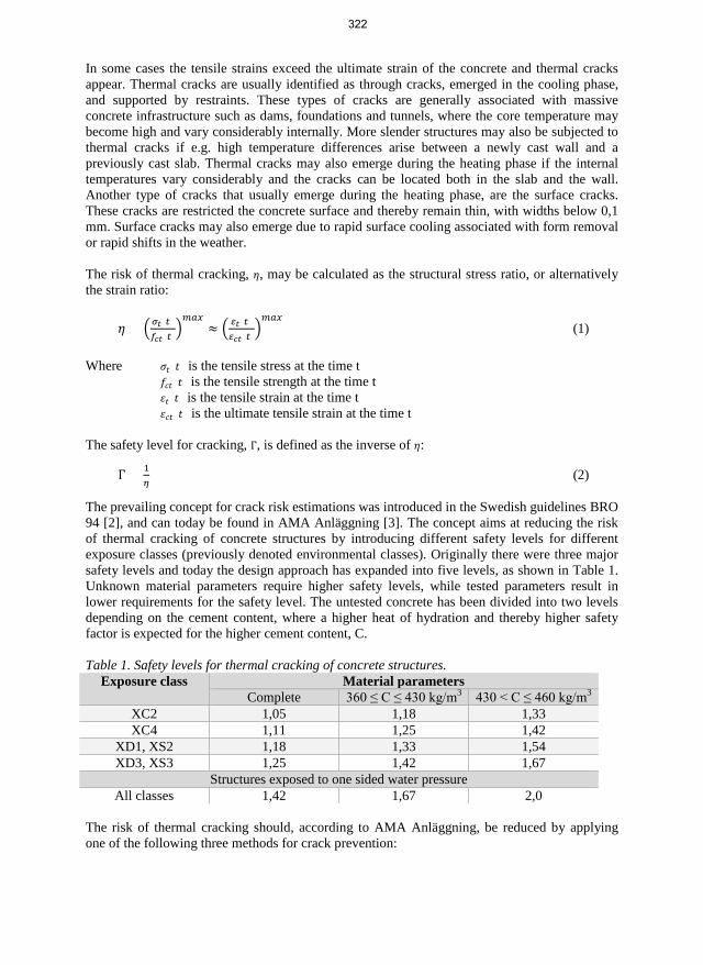
In some cases the tensile strains exceed the ultimate strain of the concrete and thermal cracks appear. Thermal cracks are usually identified as through cracks, emerged in the cooling phase, and supported by restraints. These types of cracks are generally associated with massive concrete infrastructure such as dams, foundations and tunnels, where the core temperature may become high and vary considerably internally. More slender structures may also be subjected to thermal cracks if e.g. high temperature differences arise between a newly cast wall and a previously cast slab. Thermal cracks may also emerge during the heating phase if the internal temperatures vary considerably and the cracks can be located both in the slab and the wall. Another type of cracks that usually emerge during the heating phase, are the surface cracks. These cracks are restricted the concrete surface and thereby remain thin, with widths below 0,1 mm. Surface cracks may also emerge due to rapid surface cooling associated with form removalor rapid shifts in the weather.
The risk of thermal cracking, 𝜂𝜂, may be calculated as the structural stress ratio, or alternatively the strain ratio:
𝜂𝜂 = �𝜎𝜎𝑡𝑡(𝑡𝑡)𝑓𝑓𝑐𝑐𝑡𝑡(𝑡𝑡)
�𝑚𝑚𝑚𝑚𝑚𝑚
≈ � 𝜀𝜀𝑡𝑡(𝑡𝑡)𝜀𝜀𝑐𝑐𝑡𝑡(𝑡𝑡)
�𝑚𝑚𝑚𝑚𝑚𝑚
(1)
Where 𝜎𝜎𝑡𝑡(𝑡𝑡) is the tensile stress at the time t 𝑓𝑓𝑐𝑐𝑡𝑡(𝑡𝑡) is the tensile strength at the time t 𝜀𝜀𝑡𝑡(𝑡𝑡) is the tensile strain at the time t 𝜀𝜀𝑐𝑐𝑡𝑡(𝑡𝑡) is the ultimate tensile strain at the time t
The safety level for cracking, Γ, is defined as the inverse of 𝜂𝜂:
Γ = 1𝜂𝜂 (2)
The prevailing concept for crack risk estimations was introduced in the Swedish guidelines BRO 94 [2], and can today be found in AMA Anläggning [3]. The concept aims at reducing the risk of thermal cracking of concrete structures by introducing different safety levels for different exposure classes (previously denoted environmental classes). Originally there were three major safety levels and today the design approach has expanded into five levels, as shown in Table 1. Unknown material parameters require higher safety levels, while tested parameters result in lower requirements for the safety level. The untested concrete has been divided into two levels depending on the cement content, where a higher heat of hydration and thereby higher safety factor is expected for the higher cement content, C.
Table 1. Safety levels for thermal cracking of concrete structures. Exposure class Material parameters
Complete 360 ≤ C ≤ 430 kg/m3 430 < C ≤ 460 kg/m3 XC2 1,05 1,18 1,33 XC4 1,11 1,25 1,42
XD1, XS2 1,18 1,33 1,54 XD3, XS3 1,25 1,42 1,67
Structures exposed to one sided water pressure All classes 1,42 1,67 2,0
The risk of thermal cracking should, according to AMA Anläggning, be reduced by applying one of the following three methods for crack prevention:
322

Method 1: Temperature requirements may be applied for the concrete and the surrounding air. Certain requirements for the geometry, cement content and structural restraints should also be fulfilled.
Method 2: Some typical design cases were studied in [4] and the most representative case, with associated design parameters and crack preventing actions, may be applied.
Method 3: Using sophisticated computer software to calculate the risk of thermal cracking and customize the crack preventing actions. The applied software should be thoroughly validated and the material parameters should be known.
2 METHOD The method for this project can roughly be divided into 6 steps:
1. Identifying relevant structures with adequate documentation.2. Studying construction documentation.3. Checking preliminary thermal crack risk estimations and actual crack preventing
measures based on expected parameters.4. Carrying out post-project thermal crack risk estimations based on actual parameters, i.e.
Method 3 according to AMA Anläggning.5. Field inventory of emerging thermal cracks.6. Analysis of the procedure and accuracy of crack risk estimations.
Three concrete structures were chosen for this project: a railway tunnel in Gamla Uppsala (2016) and two existing portal frame bridges in Ulriksdal (1990) and Antuna (1993). The structural parameters are found in Table 2. The structures were analyzed in 2D with ConTeSt Pro 5.0, a commercial FEM software developed for purpose of temperature, strength and crack risk calculations in young concrete.
Table 2. Structures analyzed in this paper. Name of structure
Year of construction
Length Cast length (walls)
Height Wall thickness
Gamla Uppsala 2014-2016 610 m 10,0 m 9,5 m 0,7 m Ulriksdal 1989-1990 41,6 m 10,4 m 6,0 m 0,8-1,2 m Antuna 1993 35 m 35 m 5,0 m 0,45 m
3 RESULTS Table 3 shows a presence of thermal cracks for all walls with η > 0,70 in the post-design and a few thermal cracks could also be seen on walls with even lower strain ratios. No temperature cracks were supposed to be formed according to the preliminary design for Gamla Uppsala, Ulriksdal or Antuna. Three casting sequences of the Gamla Uppsala tunnel exceeded their limiting strain ratio η = 0,90 in their post-design. However, temperature cracks were found on 10 out of 14 analyzed sections. Small surface cracks, < 0,1 mm openings, were also studied and counted in the crack inspection and the amount of small cracks ranged from 6 – 38 cracks for each casting. For Ulriksdal, one out of four casting sequences exceeded the limiting strain ratio η = 0,70 (based on exposure class XD3/XS3 and a cement content of 390 kg/m3) in the post-design and temperature cracks were found on two sections during the visual inspection. The single casting of Antuna was not supposed to crack according to neither the preliminary design, nor the post-design, and no temperature cracks were indeed detected.
323

Crack risk estimations according to the Swedish standards have probably reduced the amount of thermal cracks in the Swedish infrastructure, but there are still a large number of uncertainties involved in the design. Based on the results of this study, it seems relevant to question whether higher strain ratios than 0,70 should be allowed.
Table 3. Summary of the preliminary- and post-designs for thermal crack risks. Seq. Exposure
class η
Limit η
Preliminary η
Post Temp. cracks
>0,1 mm Average crack
width, mm Small cracks
≤0,1 mm Gamla Uppsala
3.1.1
XC4/XF4
Tested material
parameters
0,90
0,57 0,58 1 0,20 25 3.1.2 0,77 0,55 0 - 6 3.2.1 0,77 0,97 1 0,20 30 5.1.1 0,77 0,67 0 - 23 5.1.2 0,77 0,90 1 0,30 38 5.2.1 0,77 1,01 1 0,20 27 5.2.2 0,77 0,75 1 0,30 11 6.1.1 0,77 0,65 1 0,20 28 6.1.2 0,77 1,04 2 0,40 15 6.2.1 0,77 0,69 0 - 31 8.1.1 0,57 0,49 0 - 13 9.1.2 0,77 0,81 4 0,40 8 9.2.2 0,77 0,74 2 0,20 32
10.2.2 0,77 0,84 3 0,37 17 Ulriksdal
1 XD3/XS3
360 < C < 430
0,70
0,70 0,693 1 0,4 - 2 0,70 0,461 0 - - 3 0,70 0,438 0 - - 4 0,70 0,809 3 0,27 -
Antuna 1 XD3/XS3 0,70 0,70 0,55 0 - -
ACKNOWLEDGEMENTS Trafikverket, SBUF, Heidelberg cement, Cementa, The Elsa & Sven Thysell Foundation. Petter Eriksson and Jan-Erik Jonasson at LTU, Kjell Wallin at Betong & Stålteknik and Vilmer Andersson-Wass at PEAB.
REFERENCES
[1] De Schutter, G., Taerwe, L.: “Degree of hydration-based description of mechanicalproperties of early age concrete”, Materials and Structures, Vol. 29, No. 335, (1996)
[2] Vägverket: “BRO 94, Allmän teknisk beskrivning för broar”, Vägverket, Borlänge, VVPubl 1999:20, (1999)
[3] Svensk Byggtjänst: “AMA Anläggning 13. Allmän material- och arbetsbeskrivning föranläggningsarbeten”, Svensk Byggtjänst, Stockholm, ISBN 9789173336406, (2014)
[4] Emborg M., Bernander S., Ekerfors K., Groth P., Hedlund H.: “Temperatursprickor ibetongkonstruktioner : beräkningsmetoder för hydrationsspänningar och diagram för någravanliga typfall. Del A, B och C”, Dept. of Civil, Environmental and Natural ResourcesEngineering, Luleå University of Technology, Report No. 1997:02, (1997)
324

Thermal crack risk estimations of concrete walls – Temperature and strain measurements correlated to the equivalent restraint method
Anders Hösthagen, M.Sc. Ph.D. Student Betong & Stålteknik [email protected] and Lulea University of Technology (LTU) Structural Engineering, SE-971 87 Luleå [email protected]
Prof, Dr. Jan –Erik Jonasson Lulea University of Technology Structural Engineering, SE-971 87 Luleå [email protected]
Prof, Dr. Mats Emborg Lulea University of Technology Structural Engineering, SE-971 87 Luleå [email protected] and Betongindustri AB Box 47312, SE-100 74 Stockholm [email protected].
Dr. Martin Nilsson Lulea University of Technology Dept. of Structural Engineering Email: [email protected]
325

ABSTRACT Self-induced non-elastic deformations in hardening concrete, caused by restrained volume changes due to thermal dilatation and moisture deformations, often leads to cracking. In crack risk analyses, determination of the degree of restraint is vital. One model to estimate the restraint and calculate the thermal crack risk is the Equivalent Restraint Method, ERM. The method has previously been analyzed but needs to be further examined and validated. Recordings of tunnel sections were performed and compared to calculated values by ERM. Satisfying correlation between theoretically estimated and observed temperatures, strains and time of through cracking was achieve which is promising for future implementation and testing of the method.
Key words: Thermal cracking, Early age concrete, Local restraint method, Equivalent restraint method, Modelling, Field measurement.
1. INTRODUCTION
1.1 General Restrained movements within young concrete during the construction phase, caused by thermal dilation and/or changing moist states, is a major reason for surface and through cracking [1] - [5]. It is concluded that adjoining structure or a restraining entity (rock, subgrade etc.) bonded to the young concrete increases the risk of cracking since the restraint becomes higher, see e.g. [1].
To establish possible measures against cracking, pre-calculations to analyze the risk of cracking during the heating and cooling phases are needed in Sweden for all civil engineering structures. The measures (cooling pipes or heating cables etc.) could be introduced within most calculation models if the strain level is predicted higher than approved [6]. One important action to make the strain estimations more accurate, than using standard input parameters, is to test and evaluate the material properties of the concrete carefully as e.g described in [7].
In [8], the importance to provide reliable restraint predictions is stated, especially regarding the design of a certain measure. This is certainly true when it comes to cooling of repeated construction sections as the restraint usually is difficult to estimate and may thus be an uncertain factor [9]. One way to avoid these difficulties is to establish a complete 3D model with viscoelastic-plastic behavior of the young concrete. A drawback of these kinds of models is that they are cumbersome, time consuming at calculations and suitable software is often costly.
To simplify the restraint estimation for complex structural situations, the so called Equivalent Restraint Method (ERM) [10] may thus be used. Benefits of this method involve a possibility to extract the restraint analyzed by elastic 3D calculations and implement them into the so called Compensated Plane Method (2D FEM) for young concrete, e.g. [6] and [11].
The evaluation of how well the ERM corresponds to full scale studies made in [8] was based on the correlation between theoretical and empirical temperatures along with the correlation between theoretical strain ratios and observed crack patterns for some typical cases.
This work provides a refined evaluation of the ERM compared to the evaluation made in [8]. What has been improved is that the model is enhanced with a set of fully tested parameters of the material properties and strain measurements were performed on a chosen typical full-scale case.
326

2 METHOD Within this work, a demonstration is performed of the correlation between results from ERM and empirical experiences. Concrete temperatures and strains are recorded in two walls of a real tunnel project and compared to results from a ERM model. The tunnel is cast in 10-meter long monolithic segments, consisting of two walls (denoted as “east” and “west”) and a roof slab.
The process of this work can be described as follows. 1) Laboratory tests regarding material properties of the concrete. 2) Theoretical model developed by ERM to analyze the temperature and strain development of the studied structure. 3) Onsite measurements of temperature and thermal dilation. 4) Import of onsite temperatures (ambient air, adjacent construction and fresh concrete) to the ERM - comparison of recorded theoretical temperature developments. 5) Calculations of concrete stresses and strains and comparisons with measured ones as well as time and location of cracking.
The prerequisite of the fifth step is that the tunnel walls cracks due to thermal dilatation. If they don´t crack spontaneously, heating cables in the base slab can be activated to expand the slab to force cracks in the wall.
3 RESULTS AND CONCLUSIONS The derived ERM model, used with measured, derived or estimated values of concrete and ambient air temperatures, material parameters, wind speed, filling rate, restraint and heat transfer coefficients, gave a theoretical strain ratio development of the walls examined, see examples in Figure 1.
Figure 1 – Theoretical derived strain ratios in the east and west wall. Solid and dashed arrows indicate calculated and recorded time of cracking respectively.
To analyze the risk of cracking, an average was taken over a specific area in the structure where the maximum stress ratio was calculated [12]. In Figure 1 it is seen that the estimated time of cracking for the east wall is 146 h after casting. This is one hour and six minutes prior to the time when the crack occurs at the site. The calculated average strain ratio at point of cracking is 1.01. The estimated time of cracking of the west wall is 203 h after casting, nearly two hours
-220
-170
-120
-70
-20
30
80
130
-0,5
0
0,5
1
1,5
0 48 96 144 192 240
Mea
sure
d st
rain
[µm
/m]
Calc
ulat
ed st
rain
ratio
[-]
Time [h]
East wall Calc - MaxCalc - AverageMeas- MainMeas- Ref.
-220
-170
-120
-70
-20
30
80
130
-0,5
0
0,5
1
1,5
0 48 96 144 192 240
Mea
sure
d st
rain
[µm
/m]
Calc
ulat
ed st
rain
ratio
[-]
Time [h]
West wall Calc - MaxCalc - AverageMeas - MainMeas - Ref.
327

before the observed crack, se Figure 1. Already at 146 h after casting the calculated strain ratio shows a local maximum with magnitude 1.00, but no tensile strength failure was measured.
From the study so far, it is concluded that: • ERM is suitable for cracking analyses where complicated restraint conditions are
present.• Strain measurements on site provide a good possibility for comparisons to calculation.• ERM seems to correlated well with real behaviour of a thermal cracking situation.• Future work involves evaluation of ERM for other typical cases and comparison with
other methods.
ACKNOWLEDGEMENTS The research has been supported by Swedish Contractors Fund for Research and Development, (SBUF). Sincere gratitude is dedicated to Mr Gerard James and Mr Vilmer Andersson Vass for all work at the field study as well as Mr Kjell Wallin for theoretical and practical orientated discussions.
REFERENCES [1] ACI Committee 207: “Effect of Restraint, Volume Change, and Reinforcement on
Cracking of Massive Concrete,” ACI Committee 207, ACI207.2R-95, 2002, 26 pp.[2] Emborg M, Bernander S: “Assessment of the Risk of Thermal Cracking in Hardening
Concrete,” Journal of Structural Engineering, ASCE, Vol.120, 10, 1994. pp. 2893-2912.[3] Mihashi H, Leite J P: “State of The Art Report on Control of Cracking in Early Age
Concrete,” J. Advanced Concrete Technology, Vol. 2, No. 2, 2004, pp.141–154.[4] Kianousha M R, Acarcanb M, Ziari A: “Behavior of base restrained reinforced concrete
walls under volumetric change,” Engineering Structures, No. 30, 2008, pp.1526–1534.[5] Cusson D, Repette W: “Early-Age Cracking in Reconstructed Concrete Bridge Barrier
Walls,” ACI Materials Journal, Vol. 97, No. 4, July/August 2000, pp. 438-446.[6] Nilsson M: “Restraint Factors and Partial Coefficients for Crack Risk Analyses of Early
Age Concrete Structures,” Doctoral Thesis, Dept. of Civil, Environmental and NaturalResources Engineering, Luleå University of Technology, Luleå, Sweden, 2003, 170 pp.
[7] Fjellström P: “Measurement and Modelling of Young Concrete Properties,” LicentiateThesis, Dept. of Civil, Environmental and Natural Resources Engineering, LuleåUniversity of Technology, Luleå, Sweden, 2013, 200 pp.
[8] Hösthagen A, Jonasson J-E, Emborg M, Hedlund H, Wallin K, Stelmarczyk M: ”ThermalCrack Risk Estimations of Concrete Tunnel Segments – Equivalent Restraint MethodCorrelated to Empirical Observations,” Nordic Concrete Research, 49, 2014, pp. 127-143.
[9] Bosnjak D: “Self-Induced Cracking Problems in Hardening Concrete Structures,”Doctoral Thesis, Dept. of Structural Engineering, Norwegian University of Science andTechnology, 2000, 171 pp.
[10] Al-Gburi M, Jonasson J-E, Nilsson M, Hedlund H, Hösthagen A: “Simplified Methods forCrack Risk Analyses of Early Age Concrete - Part 1: Development of Equivalent RestraintMethod,” Nordic Concrete Research, No. 46, 2012, pp. 17-38.
[11] JSCE: “English Version of Standard Specification for Concrete Structures 2007”, JapanSociety of Civil Engineer, JSCE, December 2010, 503pp.
[12] Larson M: “Thermal Crack Estimation in Early Age Concrete – Models and Methods forPractical Application” Doctoral Thesis, Dept. of Civil, Environmental and NaturalResources Engineering, Luleå University of Technology, Luleå, Sweden, 2003:20, 190 pp.
328

Session B7:
SHRINKAGE AND CREEP
329

330

Influence of varying ambient conditions on time-dependent deformations in concrete using multi-field modelling
Tobias Gasch Tech. Lic, Ph.D. student KTH Royal Institute of Technology Division of Concrete Structures SE-100 44 STOCKHOLM, Sweden e-mail: [email protected]
Anders Ansell Ph.D., Professor KTH Royal Institute of Technology Division of Concrete Structures SE-100 44 STOCKHOLM, Sweden e-mail: [email protected]
ABSTRACT Time-dependent deformations, such as creep and shrinkage, are important when dealing with durability aspects of concrete. In the current study, a multi-field analysis method is described, verified and used in a numerical study to investigate the influence of short and long term variations in temperature and relative humidity. It is found that especially the creep behaviour is significantly influenced by the seasonal variations in climate conditions and also to a lesser extent the daily variations.
Key words: Cracking, Creep, Modelling, Multi-field, Shrinkage
1. INTRODUCTIONTime-dependent deformations are important to consider when studying durability of concretestructures, and effects such as creep and shrinkage have proven difficult to explain in theory andto model using continuum based approaches. In this study, a numerical investigation is made onthe effect of varying environmental conditions on time-dependent deformations in matureconcrete.
2. MATHEMATICAL MODELAlthough the main physical property of interest here is deformations, the time-dependentbehaviour of concrete is necessarily a multi-physical problem. At a minimum the temperatureand humidity distributions inside the material should be considered. With this in mind, a multi-field model for the analysis of concrete including effects such as creep, shrinkage and crackingwas presented by the authors in [1-2] and used for this study. A brief overview of the mostimportant features of the model is given in the following.
2.1 Governing equations of the multi-field problem The deformations 𝐮𝐮 are governed by the quasi-static form of the linear momentum balance in Eq. (1) where the stress 𝛔𝛔 balances the self-weight ρ𝐠𝐠. Also in Eq. (1), the used definition of strain 𝛆𝛆 can be seen, which corresponds to an assumption of small displacements.
331

∇ ∙ 𝛔𝛔(𝛆𝛆) − 𝜌𝜌𝐠𝐠 = 0 with 𝛆𝛆 =12
[∇𝐮𝐮 + (∇𝐮𝐮)T] (1)
The distribution of the temperature 𝑇𝑇 follows the heat equation given in Eq. (2), where heat flux is governed by Fourier’s law. Parameters 𝜌𝜌𝐶𝐶𝑝𝑝 and 𝜆𝜆𝑇𝑇 are the heat capacity and thermal conductivity, respectively.
𝜌𝜌𝐶𝐶𝑝𝑝𝑑𝑑𝑇𝑇𝑑𝑑𝑑𝑑 + ∇ ∙ (−𝜆𝜆𝑇𝑇∇𝑇𝑇) = 0 (2)
Lastly, the distribution of moisture 𝑤𝑤 is given by Eq. (3), with the relative humidity 𝜑𝜑 as the driving potential of moisture flux.
𝜕𝜕𝑤𝑤𝜕𝜕𝜑𝜑
𝑑𝑑𝜑𝜑𝑑𝑑𝑑𝑑 + ∇ ∙ [−𝛿𝛿𝑤𝑤(𝜑𝜑)∇𝜑𝜑] = 0 (3)
The flux is controlled by the non-linear transport coefficient 𝛿𝛿𝑤𝑤(𝜑𝜑) and the sorption isotherm, which slope is described by 𝜕𝜕𝑤𝑤/𝜕𝜕𝜑𝜑. Following the model of Bazant and Najjar [3], 𝜕𝜕𝑤𝑤/𝜕𝜕𝜑𝜑 is here assumed constant and combined with the transport coefficient, which then directly relates the flux to changes in humidity.
2.2 Boundary conditions To complete the model, the previously defined equations need to be complemented with appropriate boundary conditions. For the mechanical part, both prescribed displacements and fluxes (loads) are used, while for the heat and moisture parts also convective type boundary conditions are used.
2.3 Constitutive behaviour for time-dependent deformations The constitutive equation needed in Eq. (1) to relate 𝛔𝛔 and 𝛆𝛆 used in [1-2] to describe the time-dependent deformation in concrete is given as:
𝛔𝛔 = (1 − 𝜔𝜔)𝔻𝔻𝑖𝑖: �𝛆𝛆 − 𝛆𝛆𝑐𝑐𝑐𝑐,𝑣𝑣−𝛆𝛆𝑐𝑐𝑐𝑐,𝑓𝑓 − 𝛆𝛆𝑡𝑡ℎ − 𝛆𝛆𝑠𝑠ℎ� (4)
The different features of Eq. (4) are described briefly in the following. Instantaneous and elastic deformation is governed by the elasticity tensor 𝔻𝔻𝑖𝑖 defined using a non-aging elastic modulus 𝐸𝐸𝑖𝑖 and Poisson’s ratio 𝜈𝜈. Aging of the elastic behaviour is included in the creep model [4]. Creep, as well as aging, is included using the Microprestress-Solidification (MPS) theory developed by Bazant and co-workers [4]. Creep in the MPS theory is described in part by solidifying non-aging viscelasticty (𝛆𝛆𝑐𝑐𝑐𝑐,𝑣𝑣) accounting for short-term creep and an aging viscous part (𝛆𝛆𝑐𝑐𝑐𝑐,𝑓𝑓) in which effects such as drying creep is accounted for. Temperature and humidity effects on aging are included using an equivalent time. Here and in [1-2], the version of the MPS theory proposed by Jirasek and Havlsek [5] is used. Drying shrinkage (𝛆𝛆𝑠𝑠ℎ) and thermal expansion (𝛆𝛆𝑡𝑡ℎ) is assumed linearly dependent on changes in 𝜑𝜑 and 𝑇𝑇, respectively.
Although not the focus of this study, cracking is important for time-dependent deformations, especially drying shrinkage. Its effect is here accounted for using a scalar isotropic damage model [6], where cracking is described by the damage parameter 𝜔𝜔 that depends explicitly on 𝛆𝛆.
332

3. NUMERICAL IMPLEMENTATIONNumerical implementation of the governing equations (1-3) of the model is made using standardprocedures of finite element analysis and solved with the software Comsol Multiphysics [7]. Forthe constitutive equation (4), all parts related to creep are integrated in time using an exponentialalgorithm [4] in a separate subroutine. Implementation of the damage model is described in [6].
4. APPLICATION OF THE MODELThe multi-field model is first calibrated and verified using laboratory measurements followed bya numerical example using the same test set-up but with in-situ measured ambient conditions.
4.1 Comparison with laboratory testing The model is calibrated using the experimental series by Bryant and Vadhanavikkit [8]; in particular the series using prisms with dimensions 600×150×150 mm3. Loaded prisms are subjected to an axial compressive load of 7 MPa and subjected to two-sided drying to simulate a continuous wall/slab with an ambient relative humidity of 0.6. First, however, total strains for fully sealed prisms are shown in Figure 1 (left) to verify the basic creep part of the model. Next, in Figure 1 (right), total strains for prisms subjected to both loading and drying are shown together with an unloaded reference case. More information on material properties and the model parameters used can be found in [1] and additional verification examples in [2].
Figure 1 – Basic creep (left) and drying creep (right) for specimens loaded at different times. Solid lines show simulations and markers experimental data by Bryant and Vadhanavikkit [8].
4.2 Effect of variable temperature and humidity under real weather conditions The calibrated model is next used to study the influence of varying ambient conditions (temperature and relative humidity) on the time-dependent deformations of concrete. The same test-specimens and load as in the laboratory setting is used, but only prisms loaded at an equivalent age of 28 days is considered. To obtain an in-situ estimate of the ambient conditions, climate data is taken from the ASHRAE Weather Data Viewer 5.0 as included in Comsol [7] for the metrological station at Flyvestation Aalborg in 2015. Hourly variation of relative humidity and temperature are shown in Figure 2 (left) together with annual means (bold solid lines).
Three test cases are investigated: concrete casted in either January or July and a reference case using the annual means of relative humidity and temperature. The total deformation for all three cases is shown in Figure 2 (right). It can be clearly seen that there is a difference in the three, although after 1 year of sustained loading the specimens subjected to hourly variation have reached a similar magnitude of deformation. However, the reference case exhibits a significantly
333

lower deformation. Apart from seasonal thermal effects, this is mainly due to the influence that varying ambient conditions has on aging and especially the viscous strain component 𝛆𝛆𝑐𝑐𝑐𝑐,𝑓𝑓. It can be concluded that it is mainly the seasonal variation that plays an important role, but also daily variations has an effect on the aging behaviour.
Figure 2 – Left: Hourly variation of temperature and humidity in Aalborg 2015. Right: Deformations under different ambient weather conditions.
5. CONCLUSIONSA multi-field model for time-dependent deformations in concrete (cracking, creep, shrinkageand thermal expansion) has been implemented and verified using experimental data. In anumerical investigation it was, furthermore, shown that ambient climate conditions, especiallytheir seasonal variation, have a significant influence on the total deformations.
ACKNOWLEDGMENT The research presented was carried out as a part of “Swedish Hydropower Centre -SVC”. SVC has been established by the Swedish Energy Agency, Energiforsk and Svenska Kraftnät together with Luleå University of Technology, KTH Royal Institute of Technology, Chalmers University of Technology and Uppsala University. www.svc.nu.
REFERENCES [1] Gasch, T.: “Concrete as a multi-physical material with applications to hydro power
facilities”, Lic. thesis, KTH Royal Institute of Technology, Stockholm, Sweden (2016)[2] Gasch T., Malm R., Ansell A.: “A coupled hygro-thermo-mechanical model for concrete
subjected to variable environmental conditions”, Int J Solids Struct, 91:143-156 (2016)[3] Bazant Z-P., Najjar L.: “Nonlinear water diffusion in nonsaturated concrete”, Matriaux et
Construction, 5 (1):3–20 (1972)[4] Bazant Z-P., Hauggaard A., Baweja S., Ulm F-J.: ”Microprestress-Solidification theory
for concrete creep.I: Aging and drying effects”, J Eng Mech-ASCE, 123(11):1188–1194(1997)
[5] Jirasek M., Havlasek P.: “Microprestress-Solidification theory of concrete creep:Reformulation and improvement”, Cement Concrete Res, 60(0):51–62 (2014)
[6] Gasch T., Ansell A.: “Cracking in quasi-brittle materials using isotropic damagemechanics”, Proceedings, Comsol Conference 2016, Munich, Germany (2016)
[7] “Comsol Multiphysics ver 5.2a Documentation”, Comsol AB, Stockholm, Sweden (2016)[8] Bryant H-A., Vadhanavikkit C.: “Creep, shrinkage-size, and age at loading effects”, ACI
Mater J, 84:117-123 (1987)
334

Analysis of the interaction between rock and shotcrete for tunnel support
Andreas Sjölander Tech. Lic., PhD Student KTH Royal Institute of Technology Division of Concrete Structures SE-100 44 STOCKHOLM, Sweden e-mail: [email protected]
Anders Ansell Ph.D., Professor KTH Royal Institute of Technology Division of Concrete Structures SE-100 44 STOCKHOLM, Sweden e-mail: [email protected]
ABSTRACT The first part of a project aiming at increase the knowledge and understanding of how shotcrete (sprayed concrete) in interaction with rock could better be modelled is presented. The study focus on how an irregular thickness of shotcrete will affect its structural capacity. Examples show that continuously bonded shotcrete have an ability to redistribute local stresses while partly de-bonding leads to localized, wide cracks. One goal is to obtain a better understanding for how and why cracking and bond failure is initiated. The results obtained so far are here briefly summarized and commented, also showing some examples of results.
Key words: Cracking, Fibres, Modelling, Structural Design, Testing.
1. INTRODUCTIONReliable shotcrete (sprayed concrete) reinforcements are very important for the safety of tunnelsand subspace structures in hard rock. Particularly the shotcrete bonding properties and theinteraction with the underlying rock during shrinkage is of interest. Tunnels are for stabilityreasons often designed with arch-shaped ceilings and together with the complex geometries thatcan arise at connections to other tunnels and openings make it complicated to describe thisinteraction. The situation is made even more complex due to the uneven shape of the rocksurfaces in excavated tunnels and caverns. The performance of the shotcrete depends largely onthose irregularities which may affect the load carrying capacity both positively and negatively. Itis also difficult to obtain a uniform shotcrete thickness when spraying on an irregular surface.The expected behavior of shotcrete reinforcement is thus today difficult to predict in the designphase and it is also difficult to determine the cause of damage that may occur. Therefore it isdifficult to obtain feedback in order to avoid similar problems in future projects.
335

2. PREVIOUS RESEARCHThe research at KTH Concrete Structures has contributed to the international expertise ofshotcrete as rock reinforcement since the 1970s, see e.g. [1] where the behavior of bolt anchoredshotcrete reinforcements was investigated. In [2], finite element (FE) calculations were used tostudy the effect of an uneven shape of the shotcrete with respect to its capacity and stiffness.Also other researchers have studied the effect of irregularities in shotcrete linings (see [3]) andfound that varying thickness leads to stress concentrations that may lead to extensive cracking,which also have been observed in situ during mapping and measurements of shotcrete thickness.Motivated by in situ measurement results a laboratory study of shotcrete material properties,such as shrinkage and bond, was initiated at KTH [4]. This has now been followed by a projectstudying the effects of irregular shotcrete geometries, with a first phase just completed, [5].Restrained and un-restrained shrinkage of shotcrete was studied using FE modeling, where thenon-linear effects of shrinkage was described using a multi-physical model. How the irregulargeometry and thickness affect the shotcrete load carrying capacity when subjected todeformations from extruding rock blocks have also been studied. A numerical model suitable forprobabilistic design was introduced and field data was used to describe the expected distributionin shotcrete thickness. Based on an experimental set-up in [1], the peak load was then comparedbetween linings with uniform and irregular geometry, see [5,8]. For verification of the resultsare e.g. the experimental data from [4] used, see Fig. 1. The results obtained so far are herebriefly summarized and commented, also showing some examples of results. Extensivepresentations are given in [5-8].
Figure 1 – Experimental shrinkage testing with end-restrained shotcrete slab. From [4] and [5].
3. UNIFORM, RESTRAINED SHRINKAGEIn situ observations and experimental results have shown that shotcrete with a continuous bondto a stiff substrate, e.g. rock, can redistribute local high stresses, see e.g. [6]. This means thatmore fine and narrow cracks forms instead of few and wide cracks, which is beneficial fromstructural and serviceability point of view. Analytical studies have been performed using a FEmodel based on the geometry of the tested shotcreted slabs shown in Fig. 1, but here with theassumption of full bond between rock and shotcrete. An example of the results is shown in Fig.2 where it can be seen that there are only a few of the cracks crossing the entire widths of theslabs, but that there are relatively many edge-cracks with a length of 100 mm or less. It can alsobe noted how the crack pattern distributes around areas with larger thickness. Due to the bond tothe subsurface most of the cracks are surface cracks, which mean that sections of the slab didnot separate as in the laboratory tested slabs [4].
336

Figure 2 – Topographical and sectional plots with crack patterns for fully bonded slab. Numerical result from [6] with measurements in (mm).
4. NON-LINEAR, END-RESTRAINED SHRINKAGEThe same FE model as used in the above case was also adopted for analysis of shotcrete withoutbond to the surface but subjected to end-restraints, i.e. the exact case described by the test set-upin Fig. 1. An example of the results is shown in Fig. 3, where it should be noted that the partshown is the middle part of the slab, un-restrained from the substrate. The outer areas bonded toand providing anchorage with the granite are not shown. The cracks are in this case marked withsolid and dashed lines for the experimental and numerical results, respectively. As can be seenfrom the topographical plots (left side), the presented slabs only show one shrinkage crackacross the width. During testing this crack appeared closer to the centre section of the slabs, astheoretically would be the case for a perfect shotcrete slab with even thickness. However, it canalso here be seen that the cracks adapt to the surrounding topography. The rate of dryingshrinkage depends on factors such as relative humidity of the ambient air and thickness of theshotcrete. Analysis with a multi-physical modelling approach have therefore also been done [7],in which drying was described as a pure diffusion process driven by the gradient in relativehumidity. The development with shotcrete age for parameters such as compressive and tensilestrength, Young’s modulus and fracture energy was considered. The moisture model was tunedaccording to test of free shrinkage presented in [4].
Figure 3 – Topographical and sectional plots with crack patterns for end-restrained slab. Solid lines are experimental results from [4] and dashed lines numerical result from [6]. Measurements in (mm).
5. LOAD FROM MOVING ROCK BLOCKSThe case with a rock-bolted shotcrete lining subjected to load from a moving block was studiedusing a sensitivity analysis for the variation in shotcrete thickness. The load carrying capacityinfluence of an irregular shotcrete lining subjected to load from a pushing block wasinvestigated, using a 2D FE model [8]. The geometry of the models were identical to previouslyconducted laboratory investigations (see [1]), also used for evaluation of the results. Typicalresults are compared in Fig. 4, showing displaced rock blocks overlayed with shotcrete linings
337

that show de-bonding and tensile cracks due to bending. The results indicate that an irregular, varying shotcrete thickness highly affects the failure load but has a smaller impact on the deformation capacity.
Figure 4 – Numerical results for shotcrete on displaced rock blocks with plane (left) and irregular (right) surfaces. From [8].
6. FURTHER RESEARCHThe second phase of the research project involves further development of the non-linear finiteelement models used for the analyses of shotcrete on hard rock. Results from laser scanning ofrock surfaces prior to shotcreting and of the resulting shotcrete surfaces will be used as input forthe study of realistic cases. An in situ method for measurements of deformations on theshotcrete surface, due to shrinkage and rock displacement, will also be developed within theproject.
ACKNOWLEDGEMENT The presented project was supported by BeFo, The Rock Engineering Research Foundation, which is hereby gratefully acknowledged!
REFERENCES
[1] Holmgren, J.: “Punch-loaded shotcrete linings on hard rock”, PhD Thesis, KTH ConcreteStructures, Stockholm, 1979.
[2] Nilsson, U.: “Structural behaviour of fibre reinforced sprayed concrete anchored in rock”,PhD Thesis, KTH Concrete Structures, Stockholm, 2004.
[3] Malmgren, L.: “Interaction between shotcrete and rock: Experimental and numericalstudy”, PhD thesis, Luleå Technical University, Luleå, 2005.
[4] Bryne, L.E.: “Time dependent material properties of shotcrete for hard rock tunneling”,PhD Thesis, KTH Concrete Structures, Stockholm, 2014.
[5] Sjölander, A.: “Effective use of rock reinforcement in tunnels through improved analysisof the shotcrete-rock interaction (prel. title)”, Licentiate thesis, KTH Concrete Structures,Stockholm, May 2017.
[6] Sjölander, A., Ansell, A.: “Numerical simulations of restrained shrinkage cracking in glassfibre reinforced shotcrete slabs”, Submitted to Advanced Cementitious Building Materialswith Applications in Civil Engineering, 2017.
[7] Sjölander, A. Gasch, T. Ansell, A., Malm, R.: “Shrinkage cracking of thin irregularshotcrete shells using multiphysics models”. Proceedings, 9th International Conference onFracture Mechanics of Concrete and Concrete Structures, Berkeley, USA, 2017.
[8] Sjölander, A., Bjureland, W., Ansell, A., (2017) “On failure probability of thin irregularshotcrete shells”. Proceedings, ITA-AITES World Tunnel Conference 9, Bergen, Norway.
338

Effect of water-cement ratio on plastic shrinkage cracking in self-compacting concrete
Faez Sayahi Ph.D. Student Div. of Structural and Fire Engineering Luleå University of Technology, LTU 971 87 Luleå, Sweden. [email protected]
Mats Emborg
Professor LTU/Head R&D Betongindustri AB 971 87 Luleå, Sweden. / Betongindustri AB, 100 74 Stockholm, Sweden mats.emborg@ betongindustri.se [email protected]
Hans Hedlund Professor LTU/Skanska Teknik AB 971 87 Luleå, Sweden/Skanska AB, 405 18 Göteborg, Sweden [email protected] [email protected]
ABSTRACT Plastic shrinkage cracking is a mechanical phenomenon that occurs in the first few hours after casting the concrete in its mould. It is commonly believed that rapid and excessive moisture loss of the fresh concrete, mainly due to evaporation, plays a decisive role in the early age shrinkage. However, it is not always possible to justify all the plastic shrinkage incidents based on water evaporation solely. Instead, it seems that and interconnected correlation between evaporation, capillary pressure and hydration rate may offer better explanation. In this paper effect of water-cement (w/c) ratio on plastic shrinkage cracking of self-compacting concrete (SCC) is investigates. Four recipes with different w/c ratios (0.38, 0.45, 0.55 and 0.67) are tested by using Ring test method (NT BUILD 433). During the experiments evaporation, capillary pressure and internal temperature of the specimens were recorded from 60 minutes after casting up to 18 hours, at which the length and width of the cracks were measured. The results show lower risk of cracking when w/c ratio is between 0.45 to 0.55. However, the specimens with 0.38 and 0.67 w/c ratio experienced higher cracking tendency, especially the latter, in which severe cracking was observed.
Keywords: Plastic Shrinkage, Water-cement ratio, SCC, Evaporation, Capillary pressure, Internal temperature.
339

1. INTRODUCTIONPlastic shrinkage in concrete occurs in the first few hours after mixing, due to rapid waterevaporation which in turn increases the negative pressure in the pore system, known as capillarypressure. Consequently, tensile force will be applied on the solid particles close to the concretesurface which leads to reduction of the inter-particle distances and shrinkage of the wholemixture. Since this process occurs when the concrete is still in the plastic stage, the contractionis called plastic shrinkage. If the mixture is restrained in any way and the tensile stresses exceedthe very low tensile strength of the young concrete, cracks may form at the surface from whichthey can propagate deep into the concrete element.
The period of plastic shrinkage extends from immediately after mixing until the final setting of the concrete (i.e. sum of the plastic and the semi-plastic phase) [1]. However, since no significant chemical reaction between the cement and water takes place in the plastic stage (i.e. before the initial set), the shrinkage at this phase is considered to be predominantly physically induced [2].
According to Gauss-Laplace relation, capillary pressure in a pore is inversely proportional to the radius of the meniscus which forms as a result of evaporation [2]. In other words, finer pore system and faster evaporation will cause higher capillary pressure and more tensile stresses. Meanwhile, longer plastic phase (dormant period) means that the concrete will be prone for shrinkage without any significant resistance for longer time which eventually increases the cracking risk. Hence, early-age cracking can be highly problematic in self-compacting concrete (SCC), High Performance Concrete (HPC) and/or Ultra-High Performance Concrete (UHPC) due to the relatively low water/binder (w/b) ratio and high dosage of superplasticizer (SP) [3]. Accordingly, plastic shrinkage cracking is not limited only to hot and arid regions and has become a challenge even in the cold Scandinavia [2].
In this paper the influence of w/c ratio on plastic shrinkage cracking in SCC is investigated. Although similar study have been already performed by other researchers [3], in this research effort is made in order to explain the cracking incidents based on the relation between evaporation, capillary pressure and hydration rate. The presented paper is part of an on-going PhD project at Luleå University of Technology in Sweden which aims at deepen the knowledge about the mechanism of plastic shrinkage cracking in concrete.
2. MATERIALS AND METHODSTable 1 shows the recipes of the tested SCCs of which the one with 0.67 w/c ratio is used asreference. The mixtures were produced by Byggcement (CEM II/A-LL 42.5R). The SP andmineral filler are Sikament 56 and Limus 40 (Density 2670 kg/dm3 and Blaine 380 m2/kg)respectively. The dry materials are premixed for one minute before adding the water and SP.Then the mixing continued for another 5 minutes.
Table 1: Mix design of the tested concretes ID Cement Water Agg. 0-4 Agg. 0-8 Agg. 8-16 Filler SP W/C W/C 0.38 420 160 0 1021 694 40 4.6 0.38 W/C 0.45 380 171 0 998 678 100 5.7 0.45 W/C 0.55 340 187 81 879 651 160 4.1 0.55 W/C 0.67 (Ref.2) 300 200 155 771 628 220 2.4 0.67
340

Moulds, designed based on Ring test method (NORDTEST-method NT BUILD 433), are utilized in order to determine the cracking tendency of young concrete (Fig. 1). The test setup consists of three identical moulds with two concentric stainless steel rings in each. Once the concrete is cast, the mould is covered by a transparent air funnel with a suction fan. The experiments took place, in 20 ± 1˚C room temperature and 35 ± 3% relative humidity. The weight of the evaporated water is measured using three load cells (only in one mould). Moreover, capillary pressure (at 4 cm from the surface) and internal temperature (at 2 cm from the bottom) are recorded continuously, starting at 60 minutes after the castings up to 18 hours later. Time of crack initiation was determined by visually inspecting the concrete surface every 30 minutes. At the end the average crack area was calculated, as suggested by [3], according to Eq.1:
3)( widthcracklengthcrackareacrackAverage ×∑
= (1)
Figure 1 - The arrangement of the test setup, from [3]. All the dimensions are in mm.
3. RESULTS AND DISCUSSIONThe results show that the total accumulative evaporation increases by increasing the w/c ratio(Fig. 2.a). On the other hand, the largest average crack area was measured in W/C 0.67,followed by W/C 0.38, W/C 0.55 and W/C 0.45 (Fig. 2.b) which obviously does not correspondto the evaporation trend. In W/C 0.38, the radius of the curvature of the menisci in the poresdecreases slower due to less evaporation, which leads to lower rate of capillary pressure build-up (Fig. 2.d). However, this reduction is compensated with faster hydration which eventuallyincreases the capillary pressure build-up rate (Fig. 2.c). Hence, it seems that in this case theconcrete cracks mainly due to autogenous shrinkage.
With higher w/c ratio, the cooling effect of the evaporation prolongs the hydration, i.e. longer plastic phase. The lower capillary pressure build-up rate is then compensated with faster reduction of the menisci radius due to higher evaporation. However, in W/C 0.67, the very high evaporation together with narrower pore system due to the presence of large amount of fines (Tab. 1) rapidly increases the of capillary pressure. It can be interpreted that at any given time, the amount of shrinkage in W/C 0.67, is much larger than that which is experienced by the others. For instance, in Figure 2.d, it can be seen that the capillary pressure at 4 hours after starting the measurement is -40 kPa for W/C 0.67 and -25 kPa for the other three. This means that W/C 0.67 shrinks more in comparison.
341

Figure 2 - Influence of w/c ratio on (a) evaporation, (b) average crack area, (c) internal temperature and (d) capillary pressure.
4. CONCLUSION• High capillary pressure build-up rate can increase the cracking risk when accompanied with
high evaporation and long dormant period.• The reason that the cracking tendency increases after 0.55 w/c ratio is the presence of large
amount of fillers which leads to faster capillary pressure development.• Cracking in SCC with high w/c ratio is mainly due to plastic shrinkage, while autogenous
shrinkage is the main reason behind cracking in SCC with low w/c ratio.• The optimum range of w/c ratio in order to decrease the risk of early-age cracking is
between 0.45 and 0.55.
ACKNOWLEDGMENT The authors would like to appreciate the support they received from the Development Fund of the Swedish Construction Industry, SBUF, as well as the personnel of Complab at LTU.
REFERENCES [1] Mindess, S., Young, J.F. and Darwin, D., 2003: "Concrete", 2nd Edition, Prentice Hall,
New Jersey, 2003.[2] Sayahi, F.: ”Plastic shrinkage cracking in concrete”, Licentiate thesis. Luleå University of
Technology.[3] Esping, O., & Löfgren, I.:"Cracking due to plastic and autogenous shrinkage-Investigation
of early age deformation of self-compacting concrete-Experimental study", Technicalreport, Chalmers University of Technology, Sweden, 2005.
342

Interface stresses in concrete bridge deck overlays subjected to differential shrinkage
Martin Persson PhD-student Div. Structural and Fire Engineering, Luleå University of Technology/ 971 87 Luleå, Sweden Ramböll A/S, Skeppsgatan 5, 211 11 Malmö, Sweden [email protected] / martin.persson @ramboll.se
Ulf Ohlsson Ass prof Div. Structural and Fire Engineering, Luleå University of Technology 971 87 Luleå, Sweden. [email protected]
Johan Silfwerbrand Professor, Head Dep. Civil and Architectural Engineering Dep of Struct and Arch Engineering Div., Royal Inst of Technology 100 44 Stockholm, Sweden. [email protected]
Mats Emborg Professor, LTU/Head of R&D Betongindustri AB Div. Struct and Fire Eng, Luleå University of Technology 971 87 Luleå. Betongindustri AB, 100 74 Stockholm, Sweden [email protected]/[email protected]
ABSTRACT Concrete overlays on bridge decks are expected to be more durable as compared with the more common asphalt solution. Besides stresses due to traffic load and temperature variations at service, the overlays are exposed to stresses due to long term shrinkage. Of interest is to evaluate the concrete overlay due to the shrinkage induced stresses at the composite interface. Three strategies have been employed to gain knowledge on the stresses; 1) use of non-destructive test systems via field observations, 2) a numerical study on a concrete composite slab tested in laboratory, 3) recordings of realistic shrinkage and climate data on a reference bridge using vibrating strain gauges and humidity probes in the newly cast concrete overlay. The data were used as input data for a linear elastic finite element model. This article demonstrates this last phase of the work.
Keywords: Concrete bridge overlay, shrinkage, full scale recording, FEM, shear stresses
343

1. INTRODUCTIONThe bonded concrete overlay technique has several important areas of application; retrofitting ofconcrete structures, repair in general and road and pavement applications. One important factorwith respect to serviceability and durability of concrete overlay solutions is restrained shrinkage[1] [2]. Failure modes expected in case of differential shrinkage are de-bonding and cracking;which one that is more prone than the other is difficult to predict though it depends on e. g. thestiffness of the structural system. Aspects of importance are; time-dependent materialcharacteristics, climate conditions, workmanship and structural properties of the whole system.
Main purpose of this paper is to analyse interface load effects on a concrete composite bridge deck due to shrinkage. Addressed questions are 1) how does ambient climate conditions effect internal concrete climate, 2) what is the magnitude of interface stresses due to recorded in-situ shrinkage, 3) which type of defect appears first - vertical or horizontal cracks.
2. METHODAs mentioned earlier, as a part of a PhD project, realistic shrinkage and climate data have beenstudied on a reference bridge using vibrating strain gauges and humidity probes in the newlycast concrete overlay, see [3]. Material properties were documented on reference specimensstored in laboratory. The data were used as input data for a linear elastic finite element model.
The bridge of which measurements and analysis were performed on is a two hinges beam-frame reinforced concrete bridge with wing walls oriented parallel to its longitudinal direction, Fig 1. Shrinkage strain, climate data etc. on site were recorded in the cover and beside the bridge (non-loaded dummy samples) by use of 12 vibrating strain gauges and 12 humidity probes equipped with wire-less on line documentation facilities, provided by Roctest Ltd and Vema Venturi AB, Fig 2a. Strain and climate readings of reference concrete samples on site and in laboratory at LTU were recorded with similar principles as concrete cover readings, details are given in [3].
Finite element modelling was done by the use of ATENA Science software package. One fourth of the bridge was modelled due to an assumed double symmetric load situation due to shrinkage, thus neglecting that the whole overlay as such was cast at two occasions with four weeks in difference, Fig 2b. All elements modelling the concrete are 8-noded linear 3D solid “brick” or hexahedron, isoparametric elements integrated by Gauss integration at 8 points.
3. RESULTSFig 3 shows typical climate history (T and RH) in the concrete overlay (a) and example ofshrinkage strain readings in laboratory (b) and at the site (c). While the laboratory storedspecimens show contraction the site readings show a mix of expansion and contraction - areason that has been difficult to explain. Fig 3d shows typical interface shear stress from FE.
4. DISCUSSION AND CONCLUSIONSAll strain values are small in general compared to what was expected but could be explained toan extremely favourable humid climate at the time of curing and months afterwards duringautumn. Moreover, a more or less constant access of evaporating water from the river might be afactor reducing the shrinkage even further. Next spring may give a higher shrinkage of the cover– this will be evaluated in future work. The work will end up in recommendations andguidelines to support future design and executions, see discussions in e.g. [4].
The following comments and conclusions on the study so far can be identified:
344

• No surface cracks were found up to late autumn (some four months after casting)• Strain and climate readings from the bridge could be documented wireless during more
than 300 days without any larger interruptions and other possible problems.• Small shrinkage values are obtained due to favorable, humid, climate conditions.• Small interface stresses were obtained in FE analyses based on autogenous shrinkage
strain from in-situ placed specimens.• The results will be a base for further development of FE model as well as for
establishing recommendations/guidelines.
Fig 1. Studied bridge with a span of 25 m and a total length of 37.5 m, bridge deck width: 6.9 m. Concrete overlay casting of one traffic lane.
a) b) Fig 2. a) Parts of test setup on site: head unit for web/energy/storage service and grid with 6 vibrating wire gauges b) Finite element ATENA model. 1/4th of the geometry, 25 000 elements.
345

a) b)
c) d) Fig 3. a) Climate data (first 118 d) b) Example of shrinkage - indoor specimens c) example longitudinal overlay strain (first 300 d) d) FEM interface shear stress [MPa,] outer1/4 part
ACKNOWLEDGEMENTS The authors express their special thanks and gratitude to Swedish Transport Administration (Trafikverket) and LTU, funding the project.
REFERENCES [1] Beushausen H, Alexander M “Failure mechanisms and tensile relaxation of bonded
concrete overlays subjected to differential shrinkage”. Cement and Concrete Research36(10):1908–1914 (2006)
[2] Bissonnette B, Courard L, Fowler D, Granju J, Silfwerbrand J “Bonded Cement-BasedMaterial Overlays for the Repair, the Lining or the Strengthening of Slabs or Pavements”:State-of-the-Art Report of the RILEM Technical Committee 193-RLS, RILEM State- of-the-Art Reports, Springer, Netherlands (2011)
[3] Persson M, Ohlsson U, Emborg M, Silfwerbrand J, Farhang A”Interface stress analysison a concrete bridge deck overlay subjected to shrinkage – field measurements andnumerical analysis" Technical report, Luleå Univ of Techn Luleå, Sweden (2016)
[4] Sundquist H (Editor & co-author) ”Robustare brobaneplatta”, State-of-the-art och förslagtill FUD program. Sveriges Bygguniversitet, Stockholm, Sweden, (2011)
346

Session B8:
CONCRETE RHEOLOGY AND OTHER PROPERTIES OF FRESH CONCRETE
347

348

The Particle-Matrix model: limitations and further improvements needed
Rolands Cepuritis Dept. of Structural Eng., NTNU Richard Birkelands vei 1A, N-7491 Trondheim,NorwayE-mail: [email protected]
Stefan Jacobsen Dept. of Structural Eng., NTNU Richard Birkelands vei 1A, N-7491 Trondheim,NorwayE-mail: [email protected]
Jon Spangenberg Department of Mechanical Engineering, DTU Produktionstorvet, Building 425, room 224 2800 Kgs. Lyngby, Denmark [email protected]
ABSTRACT According to the Particle-Matrix Model (PMM) philosophy, the workability of concrete depends on the properties of two phases and the volumetric ratio between them: the fluid matrix phase (≤ 0.125 mm) and the solid particle phase (> 0.125 mm). The model has been successfully applied to predict concrete workability for different types of concrete, but has also indicated that some potential cases exist when its application is limited. The paper presents recent studies on improving the method by analysing how the PMM one-point flow parameter λQ can be expressed by rheological models (Bingham and Herschel-Bulkley).
Key words: Rheology, matrix, FlowCyl, yield stress, plastic viscosity.
1. INTRODUCTION AND BACKGROUND
1.1. The Particle-Matrix Model (PMM) To simplify the practical modelling of the effect of different concrete part materials on concrete workability, Ernst Mørtsell developed a material model called the Particle-Matrix Model (PMM) as a part of his doctoral thesis at the Norwegian University of Science and Technology in 1996 [1]. According to the PMM philosophy, the workability of concrete depends on the properties of two phases: the fluid matrix phase (≤ 0.125 mm) and the solid particle phase (> 0.125 mm), i.e. a liquid phase (matrix) and a friction material (particles):
349

The lubricating concrete matrix phase is defined as consisting of all fluids (water,admixtures, etc.) and particles (binder, filler, fines from the aggregate, etc.) ≤ 0.125 mm.This definition was chosen to acknowledge that very small particles will mainly affectproperties of the fluid matrix phase due to their surface properties whereas gravity playsa small role when the particles are dispersed in a fluid. It is therefore natural to let thesmall particles and entrained air by definition belong to the matrix;
The particle phase dispersed in the lubricating matrix is defined as all the particles inconcrete > 0.125 mm, which are in general the aggregate particles. The effect of theseparticles on concrete flow is mainly governed by density, shape and size distribution.
In practice, the PMM approach is based on a single-parameter characterisation of each phase, i.e. the flow resistance ratio of the matrix and the air voids modulus of the particles:
The flow resistance ratio (λQ) is a one-point workability parameter determined in theFlowCyl test, which is a simple flow viscometer – a modification of the Marsh Cone testapparatus (see in [1] and [2] for details);
The air voids modulus (Hm) is based on the air voids space ratio of the fine (0.125-4mm) and coarse (> 4 mm) portions of the particle system. Details on the determination ofthis parameter can be found in [1] and [2].
Figure 1: Slump value as a function of matrix volume for two concretes based on the same particle system, but different matrix compositions [3].
Mørtsell [1] demonstrated that, when the properties of the two phases are determined in this simple way, the workability of the concrete depends on these properties and the volume ratio between them. The workability of the concrete as characterised by the slump and flow measure (or another rheological parameter) is then finally expressed as a function of the flow resistance ratio of the matrix, the air voids modulus of the particle phase, and the volume fraction of the matrix. Mørtsell [1] chose the hyperbolic tangent (tanh) function as a basis for his workability function, which then resembles an “S-shape” in matrix volume vs. slump (also slump-flow, yield stress or any other workability parameter) coordinates (Figure 1). The syntax and use of these functions are described in detail in [1] and [2].
1.2. Current recognised limitations of the PMM Ernst Mørtsell showed in his doctoral thesis [1] that the PMM is applicable for conventional (vibrated) normal-weight Norwegian concrete mixes with consistencies of up to about 250 mm
Low viscosity matrix
High viscosity matrix
350

of slump, based on natural sand and matrices with relatively low fines content. Later, Smeplass [2] demonstrated that the PMM is also applicable to light-weight aggregate concrete (LWAC)based on natural sand and coarse lightweight aggregates, i.e. no modifications are required tohandle the reduced density of the LWAC.
Smeplass and Mørtsell [6] investigated the applicability of the PMM to self-compacting concrete (SCC). Their study included both high-strength SCC based on high-strength ordinary Portland cement (OPC) without additional fillers and low-strength SCC based on regular OPC with substantial filler additions. The hypothesis for the study was that the PMM would work even better with the matrix-dominated SCC mixes, and that the workability of the SCC mixes tested would be a unique function of the flow resistance ratio of the matrix and the volume of the matrix according to the PMM. However, the results revealed that, to achieve a slump-flow measurement of approx. 650 mm, the necessary matrix volume was 40-80 l/m3 lower for the mixes based on the high-strength OPC than for the regular OPC mixes, when all other parameters (including λQ values) were comparable. In other words, the researchers did not find a simple correlation between the flow resistance ratio of the matrix (λQ) and the workability of the SCC. Smeplass and Mørtsell [6] proposed that the problem was in the measuring device used for the characterisation of the matrix, i.e. the FlowCyl. They suggested that the problem with the FlowCyl was that it gives only a single value, whereas the matrix is at least a two-parameter fluid that needs to be more fundamentally described with a yield value (τ0) and plastic viscosity (µ).
2. USING FLOW-CYL AS ONE-PARAMETER CHARACTERISATION OFMATRIX RHEOLOGY: RECENT FINDINGS
The reviewed previous research in subsection 1.2 above raises a very important question: why the FlowCyl test on matrices does not reflect the differences in concrete workability for all types of concrete, even when the particle phase is kept constant? Recently, two new studies with the goal of answering this question have been conducted by Cepuritis, et al. [5] and [6]. The studies included development of a numerical model of the FlowCyl, as well as a series of simulations of the FlowCyl test aimed at analysing the effect of the yield shear stress (according to the Bingham and Herschel-Bulkley (H-B) material models) on the flow resistance ratio λQ. The numerical results were found to be in good agreement with experimental results on rheology measurements of approx. 100 cement pastes including crushed aggregate fines (≤ 125 µm).
Figure 2: A figure of the shear rate magnitude in the FlowCyl for a cement paste after 25 seconds: left) Bingham material model right) H-B model [5].
351

Results of the investigation in [5] and [6] have revealed that that the plastic viscosity dominates the flow resistance ratio. The reason for the dominance is owed to the fact that the cement paste experiences high shear rates (approx. 200 1/s) at the outlet, see Figure 2, which is a region of the FlowCyl that has a great influence on the flow rate and thereby the flow resistance ratio.
3. CONCLUDING REMARKS: FURTHER IMPROVEMENTS NEEDEDAs a result of the findings reported in Section 2, one can state that the flow resistance ratio canbe used as a one parameter characterization of the matrix rheology, when utilized to predict theflow behaviour of concrete, such as in the PPM model, as long as the shear rates that the cementpaste undergoes during the concrete flow are high. Moreover, the PMM shall only work whencomparing mixes with similar yield stress of the matrix phase, as the yield stress of the matrix isnot represented by the flow resistance ratio value. In more practical terms this would mean thatPMM should probably work fine when the dosage of the superplasticiser (SP) is relatively highand the yield stress of the matrix phase has been reduced to be negligible. PMM should alsowork when comparing mixes where the yield stress of the matrices is the same, which wouldthen imply similar dosages of the SP and use of binders/ fines ≤ 0.125 mm that have similarinteraction with the SP molecules.
The further proposed improvements for the PMM, based on the discussion presented here, would imply finding a way so that the flow-resistance ratio also includes a contribution from the yield stress of the matrix. There are two directions for this chosen in a work in the MiKS (Mikroproporsjonering med Knust Sand (Norwegian for Micro-proportioning with Crushed Sand)) project currently in progress at NTNU. These are: supplementing the flow resistance ratio value with a mini-cone spread measurement to capture the yield-stress effect or changing the geometry of the FlowCyl so that the mass flux out of the FlowCyl and thereby the flow resistance ratio measurement would also include a contribution of the yield-stress of the matrix.
REFERENCES [1] E. Mørtsell, “Modelling the effect of concrete part materials on concrete consistency. PhD,”
Norwegian University of Science and Technology (In Norwegian), 1996.[2] S. Smeplass, “BE96-3942/R12 Applicability of the particle-matrix model to LWAC,”
EuroLightCon, Brussels, 2000.[3] R. Cepuritis, “Development of Crushed Sand for Concrete Production with Micro-
proportioning. PhD,” Norwegian University of Science and Technology, Trondheim, 2016.[4] S. Smeplass and E. Mørtsell, “The applicability of the particle matrix model to self
compacting concrete,” Nordic Concrete Research, vol. 26, 2001.[5] R. Cepuritis, E. Ramenskiy, E. Mørtsell, S. Smeplass, H. Synnøve Kjos-Hanssen, S. Li, S.
Jacobsen and J. Spangenberg, “FlowCyl: one-parameter characterisation of matrix rheology,” in Proceedings of Second Concrete Innovation Conference (2nd CIC) in Tromsø, Norway 6-8 March 2017.
[6] R. Cepuritis, E. Ramenskiy, E. Mørtsell, S. Smeplass, H. Synnøve Kjos-Hanssen, L.Shizhao, S. Jacobsen and J. Spangenberg, “FlowCyl: numerical modelling and practical limitations,” Manuscript in progress for submission to Cement and Concrete Research, 2017.
352

Segregation in concrete – should it be measured more often and how?
Lasse Frølich M.Sc., Concrete technologistCementir Research and Quality Centre AalborgSølystvej 18, DK-9220 Aalborg Øe-mail: [email protected]
ABSTRACT Correlation between different methods for determination of segregation in self-compacting concrete has been studied. It is demonstrated that visual assessments (normally the only assessment) in some cases are insufficient. The study mainly deals with correlation between the US segregation column method and the European sieve segregation method. The segregation column method with some modification in the procedure, seems to produce more detailed results and segregation is actually measured directly (sieve segregation being and indirect measurement).
Key words: Segregation, SCC, Rheology, Testing.
1. INTRODUCTION
1.1 Segregation in concrete Self-compacting concrete (SCC) is widely used in Denmark and the use of this specific type of concrete is increasing in many countries. A key parameter for SCC is the robustness against segregation. Segregation occurs when coarse aggregate particles moves towards the bottom of the concrete leaving a layer of cement mortar in the top of the concrete. Concrete production will always be subjected to variations from the constituent materials and inaccuracy in dosage of materials. This will lead to day-to-day variations in the rheology of the fresh concrete and sometimes the concrete might segregate. Segregated concrete have a lower strength, is less durable and might have a poor surface finish compared to homogeneous concrete. Even though segregation seems to be critical, it is seldomly measured. The reason for this might be that segregation can be assessed visually. This type of assessment is, however, highly subjective. Visual assessment is often performed on the concrete used for the slump flow test (immediately after the test), where it is observed whether the stones are also present at the edge of the concrete. If so, the concrete is assessed to be without segregation. This gives some information on dynamic segregation, but none on static segregation. Static segregation is critical for casting of tall structures. It can seem odd not to specify a certain resistance to segregation in such castings, but also in general. In general, it could be valuable to precisely measure whether one type of cement, sand or admixture gives a higher robustness to segregation compared to another. A cheap constituent material might turn out to be the more expensive (because it produces SCC with low robustness to segregation).
353

1.2 Methods to measure segregation There are numerous methods, which can be used to determine segregation in SCC. Some examples are given below:
• Sieve segregation acc. to [1]. Segregation is determined from amount of fresh concretepassing a 5 mm sieve when placed there for 2 min
• Segregation column acc. to [2]. Segregation is determined from the difference in amount ofwashed out stones from a top and a bottom section of a column with fresh concrete (afterleaving the concrete in the column for 15 min)
• Penetration acc. to [3]. Segregation is determined from penetration of a needle measured ina slump cone. Higher penetration indicate less stones in the surface and hence segregation
• Visual assessment acc. to [4]. Stability index by visual assessment of fresh concrete from aslump flow test
• Rotational rheometer. Non-standardized method. Resistance to segregation assessed basedon yield stress and plastic viscosity of fresh concrete
• Distance to stones. Non-standardized method. A cylinder with hardened concrete is sawed intwo. Segregation is determined as the average distance from surface to stones.
The European concrete standard [5] specifies a method to determine segregation in SCC, i.e. the sieve segregation method. Specification of concrete (and measurements in general) according to this standard are, however, rare. The US method with column segregation might simulate real conditions more precisely. Therefore, this method have been the focus of this study.
2 EXPERIMENTAL
2.1 Methods Segregation has been studied with visual assessment, segregation column and sieve segregation. A 0-5 scale was used in the visual assessment (0 = no segregation and 5 = completely segregated). Assessments were based on the appearance of the concrete in a container 10 min. after mixing.
2.2 Mix designs Concrete with strength class C25/30 to C45/55 have been used for testing
3 RESULTS AND DISCUSSION
3.1 Segregation column versus visual assessment Initially results from the column method have been compared with visual assessments. Results are illustrated in figure 1. Concrete 1, 2 and 4 are the same C25/30 mix design (2 and 4 with higher water contents). Concrete 3 is a strength class C40/50. Typically, a maximum of 15 % segregation is specified for the column test in the US. This study shows that a typical Danish C25/30 SCC for flooring with a slump flow of 550 mm gives app. 5 % segregation and a typical Danish C45/55 SCC for precast elements with a slump flow 650 mm gives app. 10 % segregation. When the visual assessment of the concrete is exclusively based on the appearance of the concrete from the slump flow test, the assessment might be incorrect. For some mix designs the stones are transported to the edge of the concrete even though the concrete is segregated. An example is shown in figure 2 (concrete with 15 % segregation measured in the column test).
354
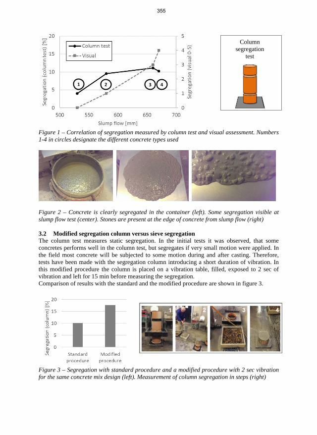
Figure 1 – Correlation of segregation measured by column test and visual assessment. Numbers 1-4 in circles designate the different concrete types used
Figure 2 – Concrete is clearly segregated in the container (left). Some segregation visible at slump flow test (center). Stones are present at the edge of concrete from slump flow (right)
3.2 Modified segregation column versus sieve segregation The column test measures static segregation. In the initial tests it was observed, that some concretes performs well in the column test, but segregates if very small motion were applied. In the field most concrete will be subjected to some motion during and after casting. Therefore, tests have been made with the segregation column introducing a short duration of vibration. In this modified procedure the column is placed on a vibration table, filled, exposed to 2 sec of vibration and left for 15 min before measuring the segregation. Comparison of results with the standard and the modified procedure are shown in figure 3.
Figure 3 – Segregation with standard procedure and a modified procedure with 2 sec vibration for the same concrete mix design (left). Measurement of column segregation in steps (right)
1 2 3 4
Column segregation
test
355
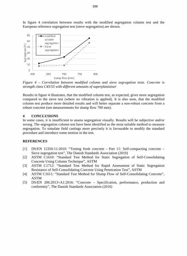
In figure 4 correlation between results with the modified segregation column test and the European reference segregation test (sieve segregation) are shown.
Figure 4 – Correlation between modified column and sieve segregation tests. Concrete is strength class C45/55 with different amounts of superplastiziser
Results in figure 4 illustrates, that the modified column test, as expected, gives more segregation compared to the sieve test (where no vibration is applied). It is also seen, that the modified column test produce more detailed results and will better separate a non-robust concrete from a robust concrete (see measurements for slump flow 700 mm).
4 CONCLUSIONS In some cases, it is insufficient to assess segregation visually. Results will be subjective and/or wrong. The segregation column test have been identified as the most suitable method to measure segregation. To simulate field castings more precisely it is favourable to modify the standard procedure and introduce some motion in the test.
REFERENCES
[1] DS/EN 12350-11:2010: “Testing fresh concrete - Part 11: Self-compacting concrete –Sieve segregation test”, The Danish Standards Association (2010)
[2] ASTM C1610: “Standard Test Method for Static Segregation of Self-ConsolidatingConcrete Using Column Technique”, ASTM
[3] ASTM C1712: “Standard Test Method for Rapid Assessment of Static SegregationResistance of Self-Consolidating Concrete Using Penetration Test”, ASTM
[4] ASTM C1611: “Standard Test Method for Slump Flow of Self-Consolidating Concrete”,ASTM
[5] DS/EN 206:2013+A1:2016: “Concrete – Specification, performance, production andconformity”, The Danish Standards Association (2016)
356

Excavated rock materials from tunnels for sprayed concrete
Judy Luong MSc student Norwegian University of Science and Technology Department of Structural Engineering Richard Birkelandsvei 1a, NO-7491 Trondheim [email protected]
Kari Aarstad Siv. Ing., Dr. ing., Senior scientist SINTEF Building, Infrastructure and Architecture Richard Birkelandsvei 3, NO-7465 Trondheim [email protected]
Klaartje De Weerdt MSc, PhD, Associate professor Norwegian University of Science and Technology Department of Structural Engineering Richard Birkelandsvei 1a, NO-7491 Trondheim [email protected]
Øyvind Bjøntegaard MSc, PhD, Senior Principal Engineer Norwegian Public Roads Administration Tunnel and Concrete section Abels gate 5, 7030 Trondheim [email protected]
ABSTRACT Sand extracted from natural resources is widely used in concrete production nowadays. The increase in demand for concrete production has resulted in shortage of natural sand resources, especially in terms of suitable materials for concrete production. At the same time, large amounts of excavated rock materials are and have been generated from tunnelling projects and discarded. Hence, there is an opportunity to use these excavated rock materials as aggregates for concrete production. The challenge lays in the production of suitable aggregates. The focus of the study presented in this paper is on the use of processed excavated rock materials from tunnelling projects as aggregates in sprayed concrete production. Five sand materials, both natural and excavated, have been characterized. The effect of three of these materials’ properties on the workability properties of the resulting spray concrete will be investigated. The study is not completed yet and a final conclusion remains to be drawn.
Key words: Aggregate, Mix Design, Reuse and Recycling, Rheology, Sustainability
357

1 INTRODUCTION High amounts of excavated rock materials are produced in infrastructure projects in Norway, especially when tunnelling is involved. In 2015, 7 million m3 rock material was excavated from Norwegian mountains [1]. Most of this material has traditionally been used as landfill or placed in deposits in lakes or fjords. However, this practice is becoming more and more controversial, and the project Local Materials (Kortreist stein) was established to accommodate extended use of this material. Four areas of possible utilization have been identified in this project: Asphalt, concrete, road construction and ballast, sub- and super structures in railway. This paper is limited to the study of the utilization of excavated rock materials in sprayed concrete production as tunneling projects often require high volumes of sprayed concrete. Utilizing the excavated rock materials in this manner may be both economically, logistically and environmentally beneficial.
2 MATERIALS AND METHODS
2.1 Materials In total five different types of sand materials from three different sources have been included in the study. The most essential information about these materials is summarized in Table 1. Three of these sand materials are processed excavated rock materials from two ongoing tunnelling projects in Norway, the new Ulriken tunnel and the Follo Line tunnel. The Follo Line connects Oslo and Ski with a 20 km long double track railway tunnel, and the Ulriken tunnel is an 8 km long double track railway tunnel between Bergen and Arna. Both tunnels are mainly driven by Tunnel boring machines (TBM), but the method drill&blast (D&B) is also applied. Furthermore, the natural sand materials from Årdal (Norstone AS) have been included in the study as reference materials for comparison with the crushed sand materials.
Table 1 - Description of the sand materials used in the study.
Name Source Particle sizes
Type of aggregate
Production process Rock typesMain
processSecondary process
MR1 Årdal 0 – 8 mm Natural Glaciofluvial and moraine deposit
Partly crushed Washed
Dark rocks Granite/gneissFeldspathic rocks
MR2 Årdal 4 – 8 mm Natural Glaciofluvial and moraine deposit
Partly crushed Washed
Dark rocks Granite/gneissFeldspathic rocks
MU1 Ulriken 0 – 4 mm Crushed Tunneling D&B
Crushed Washed
Dark rocks Granite/gneissFeldspathic rocks
MU2 Ulriken 0 – 4 mm Crushed Tunneling D&B Crushed
Dark rocks Granite/gneissFeldspathic rocks
MF Follo-banen 0 – 8 mm Crushed Tunneling
TBM Crushed Washed Granite/gneiss
The natural sand materials from Årdal, MR1 and MR2, are partly processed in terms of crushing of particles greater than 22 mm and washing [2]. The sand materials from Ulriken, MU1 and MU2, are crushed from the larger rock fragments that are produced during the traditional tunnelling method drill&blast. The crushing process includes a jaw crusher, a gyratory crusher and a cone crusher [3]. The sand material from Follo Line is produced by crushing TBM muck
358

into smaller particles [4]. The crushing includes a cone crusher and a Vertical Shaft Impacter (VSI).
2.2 Experimental program
Characterization Only the properties that are considered as relevant have been declared and included in the study. These properties are grading, fines content, particle density and water adsorption, particle shape and free mica content.
Mix design Sprayed concrete mix design from a commercial ready-mix concrete supplier has been used as basis for the proportioning part. Three mixes have been proportioned: one mix containing 50% MR1, 45 % MU1 and 5 % MR2, one mix containing 50 % MF and 50 % MR1 and finally one reference mix containing 100 % MR1. MU1 is MR2 combined to form one unit, containg particles with sizes in the entire range of interest (0 – 8 mm). MU2 is excluded in the study of fresh concrete properties due to its high content of fines (see Table 2), which is known to have a negative impact on workability properties.
FlowCyl test and void content measurement The FlowCyl test and the void content measurements are based on the particle-matrix model [5]. In the particle-matrix model, fresh concrete is considered as a two-phase system, consisting of a flowable part, the matrix phase, and a friction part, the particle phase. The FlowCyl test and the void content measurements will and have been carried out in order to characterize the properties of the matrix phase and the particle phase, respectively. According to the particle-matrix model, the workability of fresh concrete is determined by the properties of the phases and the volume ratio between them. Hence, the results of these experiments can give an indication of the workability properties of the sprayed concrete mixes, such that any necessary adjustments and changes on the proportioning part can be made before conducting the remaining experiments.
Fresh concrete properties measurements Testing of fresh concrete properties by means of slump test, flow-table test and 4SCC have not been performed yet. These experiments will be carried out during Spring 2017.
3 RESULTS AND DISCUSSION The results of the characterization and the particle void content measurements are presented in Table 2 and Figure 1. The results confirm that the use of VSI in the crushing process provides higher particle shape quality and that the crushing process generally will generate a lot of fines and shall therefore be combined with a wet- or air classification step in order to keep the fines content within acceptable limits.
In general, low content of flaky and elongated particles, low free mica content and low particle void content is beneficial for the workability properties. As expected, Table 2 shows that MR1 has the highest particle shape quality, whereas MU1 and MU2 have the poorest. Consequently, the particle void content is higher in the combined sand material MR1/MF than the other combined sand material MR1/MU1/MR2 (see Figure 1). The combinations are presented as the quantity of crushed sand, specifically MF and MU1 + MR2 in percentage of total mass. MF has the highest content of free mica. This can be related to the application of VSI in the crushing process, which generally generate high amounts of fine particles. When dealing with rock types containing mica, the use of VSI may also cause high content of free mica minerals. In overall,
359

MF seems to be a more suitable aggregate in concrete production than MU1. A final conclusion remains to be drawn after the fresh concrete mixes are tested.
Table 2 - Characterized properties for the sand materials. MR1 MR2 MU1 MU2 MF
Fines content 3,0 % 0,5 % 2,7 % 14,0 % 1,5 % Particle density 2,68 Mg/m3 2,67 Mg/m3 2,96 Mg/m3 2,96 Mg/m3a) 2,76 Mg/m3 Water adsorpt. 0,3 % 0,5 % 0,1 % 0,1 %a) 0,2 % Particle shapeb) 25 % / 20 % - 70 % / 55 % 70 % / 55 %a) 40 % / 25 %Mica content 4 % - 11 % 11 %a) 24 % a) The value for MU2 is assumed to be the same as the value for MU1.b) The values indicate the percentage of flaky/elongated particles. The first value is related to the2 – 4 mm particles, whereas the second value is related to the 4 – 8 mm particles.“-“ Not declared
Figure 1 - Sieve curves (left) and void content (right) for the investigated sand materials.
ACKNOWLEDGEMENT The project Local Materials is owned by Veidekke Entreprenør AS, started in 2016 and will proceed until 2019. The project is supported by the Norwegian Research Council, and SINTEF and NTNU are research partners. The other partners in the project are: Asplan Viak, Bane NOR, Bergen kommune, Geological Survey of Norway, Hordaland Fylkeskommune, Metso Minerals, Multiconsult, the Norwegian Public Roads Administration and Veidekke Industri AS.
REFERENCES [1] Norwegian Tunnelling Society. Available from: http://nff.no/nyheter-og-
tall/fagstoff/tunnelstatestikk/. Accessed October 25th 2016.[2] Norstone Heidelberg Cement Group (2016). Available form:
http://www.norstone.no/no/ardal. Accessed March 17th 2017.[3] Løwø V. H., NCC, personal communication, 28th October 2016[4] Ytterdal, S. G., personal communication, 10th March 2017[5] Mørtsell E.: “Modelling the effect of concrete part materials on concrete consistency”,
PhD, Norwegian University of Science and Technology (1996)
360

A method for obtaining optimum packing of aggregates for concrete at the onset of flow
Yahya Ghasemi PhD-student Div. Structural and Fire Engineering, Luleå University of Technology S-971 87 Luleå[email protected]
Mats Emborg Professor LTU/Head of R&D Betongindustri AB 971 87 Luleå, Sweden./Betongindustri AB, 100 74 Stockholm, Sweden mats.emborg@betongindustri .se [email protected]
ABSTRACT Particle packing models have been studied extensively during past decades and led to development of some complex and relatively accurate predictions of packing of granular materials. While the models are capable of calculating the packing density for different volumetric share of constitutes, the concept of optimum packing remains unclear. The study aims to define optimum packing based on particle packing theory and excess water layer theory. The approach makes it also possible to calculate amount of paste that is required to put a concrete mixture at the onset of flow. Some pilot tests conducted in the laboratory showed good agreement with calculated data.
Keywords: Excess layer theory, Optimum packing, Specific surface area, Zero-slump, Mix design.
1. INTRODUCTIONWorkability is one of the most important characteristics of concrete in fresh state which insimplest scenario depends on viscosity of the paste, packing density of aggregates, particleshape, grading curve, and the amount of water in the mixture. A particle mixture with highpacking density leaves little volume of voids in the structure to be filled with paste. Reduction ofpaste and specifically cement has several benefits i.e. reduction of cost, pollution, shrinkage,cracking, etc.
Predicting the packing density of solid particles in a mixture has been studied extensively [1,2] and led to compiling some advanced and complex models such as CPM (Compressiblie Packing Model) that can estimate the packing for combination of different volume shares of the constitutes in the mixture. Models for calculating packing density have two purposes:
1- Determining predicted packing density.2- Finding the optimal blend of particles.
361
Particle packing models can calculate the maximum packing density (minimum voids) in the mixture, however, making concrete at maximum packing usually results in “harsh” concrete [3].
The current paper aims to introduce a method for mathematical calculation of optimum packing based on input from packing models and the concept of water layer theory.
2. METHODAs mentioned earlier, the approach is based excess water layer theory and void ratio in particlemixture. The basics of water layer theory and related concepts are explained in the comingsections.
2.1. Excess water layer theory The excess water layer theory was derived from excess paste layer theory originally developed for slef-compacting concrete [4,5,6]. According to excess water layer theory, in addition to the water and cement that is required to fill the voids in aggregate structure, some extra water is required for surrounding the particle with a certain layer thickness in order to overcome the interlocks in aggregates by separating them which governs flowability of the mixture. The amount of required water is directly related to specific surface of the particles. At a constant volume of water, the mixture with higher specific surface area (SSA – surface area of particles relative to their volume or mass) will have thinner water layer around the particles comparing to a mixture with lower SSA.
The main difference between excess paste layer theory and water layer theory roots in the way that the two approach view concrete mixture. According to paste layer theory, concrete is divided into paste and aggregate phase while in excess water layer theory concrete is viewed as a mixture of all particles (aggregates plus cement) and water.
2.2. Specific surface area Measuring surface area of the particles is complex, costly and in cases inaccurate process. The measurements are usually conducted using Blaine [7] or BET test [8]. Blaine test is developed for particles with relatively spherical shape and certain packing density which makes it suitable for measuring SSA of cement but not necessarily any other particle that does not fulfil the requirements of the test. BET test involves absorption of a gas (usually nitrogen) on the surface of particles, in a case where the particles include open inner pores; the surface of the pores will be included in the test results which are not of interest for concrete mix design purposes.
An alternative to conducting the measurement is to calculate the surface area of the particles based on the size distribution curve data and the assumption of spherical shape for the particles using the following equation:
𝑎𝑎𝑠𝑠𝑠𝑠ℎ = 6∑ 𝑚𝑚𝑖𝑖𝑑𝑑�𝑖𝑖.𝜌𝜌𝑠𝑠
𝑛𝑛𝑖𝑖=1 (1)
where 𝑚𝑚𝑖𝑖 is the mass of a grain fraction i, being the mass percentage of the fraction between di and di+1. �̅�𝑑𝑖𝑖 is the mean diameter of fraction i and i+1. 𝜌𝜌𝑠𝑠 is the relative density of the particles.
It is also possible to assume one of the platonic solids instead of a sphere as the representative shape of particles. Platonic solids are set of five regular, convex polyhedrons. Replacing platonic solids with spheres will not only changes the calculated value of surface area but also
362

provides the opportunity to take into account the effect of square-cube law and the pace in growth of surface area to volume ratio as the particles become smaller in size and eventually increase the accuracy of the calculations. For this purpose Eq.1 can be written in its general form:
𝑎𝑎𝑠𝑠𝑝𝑝𝑝𝑝𝑝𝑝 = ∑ 𝑆𝑆𝑆𝑆𝑖𝑖.𝑚𝑚𝑖𝑖𝑉𝑉𝑖𝑖.𝜌𝜌𝑠𝑠
𝑛𝑛𝑖𝑖=1 (2)
where SAi/Vi is the surface area to volume ratio of fraction i and is related to the assumption made for the shape of particles. The concept of square-cube law and the principals of substituting spheres with platonic solids are discussed by [9].
3. THE MODELThe suggested model works under the assumption that in addition to the water needed to fill thevoids between the particles, some extra water is required to cover the surface of the particleswith a certain thickness in order to put the mixture on the onset of flow. The thickness of thewater layer is measured as 25nm in the case that calculation of SSA is based on spherical shape[10]; the thickness of water layer is assumed to be constant for different sizes of particles.
The packing densities of the aggregates are required too in order to find the volume of the voids. Following equation is based on the volume of constitutes of a mix for a cubic meter of concrete:
𝜑𝜑𝑎𝑎𝑎𝑎𝑎𝑎 + 𝑐𝑐 + �𝑤𝑤𝑐𝑐� 𝑐𝑐 + 𝐴𝐴 = 1 (3)
where 𝜑𝜑𝑎𝑎𝑎𝑎𝑎𝑎 is the maximum packing density of aggregates, c is the volume of cement, w/c is the volumetric water to cement ratio and A is the volume of air.
Solving Eq.3 for a known packing density of aggregates and assumed volume of air results in the amount of cement and water needed to fill the voids. As the next step in the procedure, the amount of additional water needed to form a layer surrounding the particles can be calculated based on the SSA of particles:
𝑤𝑤𝑝𝑝 = 𝑆𝑆𝑆𝑆𝐴𝐴 × 𝑡𝑡𝑤𝑤 (4) 𝑤𝑤𝑡𝑡 = 𝑤𝑤 + 𝑤𝑤𝑝𝑝 (5)
where wl is the amount of water surrounding the particles, SSA is the specific surface area of all the solid particles in the mixture and tw is the thickness of water layer ( for simplification can be assumed as 25nm in the case that SSA was calculated rather than measured). Total amount of water, wt, is considered as sum of the water that fills the voids, w, and the water that is needed to form the layer around particles. Since the water to cement ratio is supposed to be constant, an additional amount of cement should be calculated to compensate for the added particle surrounding water. New values of cement and water will be replaced in Eq.3 which will result in a new value for packing density. The new packing can be considered as the optimum packing as it indicates a point close to the climax of packing diagram where the solid structure provides enough space for the amount of water and cement that puts the mixture on the onset of flow. In addition to the optimum packing value, the model can theoretically predict the amount of paste for zero-slump in the slump diagram. Moreover, adding 5 to 10% paste to the mixture will result in a recipe for workable concrete. It should be mentioned that the excess paste should be calculated for the onset of flow by implementing the same principal of having a constant thickness of water layer around the particles.
363
4. DISCUSSIONAs mentioned earlier, the suggested model provides a basis for calculation of optimum packingand the amount paste needed to put the mixture on the onset of flow. A proper estimation ofwater requirement of the mixture results in mixtures with controllable workability. Moreover,the model can be further developed to potentially be used as a mix design model once the effectof admixtures, viscosity of the paste, and the cement type is introduced to the model.
Some pilot test recipes were made based on the calculations by the model in LTU laboratory and showed promising results.
REFERENCES
[1] Larrard, F. De. “Concrete mixture proportioning: a scientific approach”. London: E & FNSpon. (1999).
[2] Toufar, W., Born, M., & Klose, E. “Contribution of optimisation of components ofdifferent density in polydispersed particles systems”. Freiberger Booklet A, pp. 29-44(1976).
[3] Fennis, S. A. A. M.“Design of ecological concrete by particle packing optimization”Dissertation, Delft University of Technology. (2011).
[4] Kennedy, Charles T. "The design of concrete mixes." In Journal Proceedings, 36, no. 2,pp.373-400 (1940).
[5] Reschke, T., E. Siebel, and G. Thielen. "Influence of the granulometry and reactivity ofcement and additions on the development of the strength and microstructure of mortar andconcrete." Concrete Technology Reports ,200, pp. 25-38 (1998).
[6] Grünewald, Steffen. "Performance-based design of self-compacting fibre reinforcedconcrete." PhD diss., TU Delft, Delft University of Technology, (2004).
[7] ASTM C204-16. Standard test method for fineness of hydraulic cement by airpermeability apparatus.
[8] Brauneur, S., P. H. Emmet, and E. Teller. "Adsorption of gases in multi molecularlayer." Journal of Am. Chemical. (1938).
[9] Ghasemi, Y. "Aggregates in concrete mix design." Lic. diss., Luleå University ofTechnology, (2017).
[10] Hunger, M., and H. J. H. Brouwers. "Flow analysis of water–powder mixtures:Application to specific surface area and shape factor." Cement and ConcreteComposites 31, no. 1 . pp. 39-59 (2009).
364

1
Reasons to the low use of self-consolidating concrete in Norway
Øyvind Fremmergård B.Sc. [email protected]
Ann Karina Lassen Assistant Professor [email protected]
Mats Fjærestrand B.Sc. [email protected]
Mahdi Kioumarsi Associate Professor [email protected]
Simen M. D. Hjelseth B.Sc. [email protected]
Affiliation: Oslo and Akershus University College (HiOA) Pilestredet 46, 0130 Oslo
ABSTRACT According to several research papers, self-consolidating concrete (SCC) should be able to offer advantages over conventional vibrated concrete (CVC) [1-3]. Nevertheless, in Norway SCC has a relatively low market share, and the use is mainly concentrated to the capitol and nearby districts. In this paper, through interviews with professionals in the construction industry, possible causes of the low use of SCC in Norway have been investigated. Lab tests have also been conducted to study effects of variations in the concrete composition, as well as the effects of poor execution that can occur due to inadequate competence of construction workers. According to the paper´s results, perceived advantages of the SCC are not nearly as many as those mentioned in various research papers [2-4].
Key words: Self-consolidating concrete, reinforced concrete, segregation, quality control, admixtures.
1. INTRODUCTIONSCC is a modern type of concrete which originated in Japan in the 1980s [5]. Due to highseismic activity, constructions in Japan require a large amount of tightly spacedreinforcement [2] which complicates the use of vibrators. In such constructions SCC is moresuitable, because the properties of fresh SCC allows it to flow and fill the formwork withoutvibration. Various research papers mention quite a few other advantages, such as improvedquality of the concrete, and overall costs lowered by up to 15% [4].
SCC might also reduce construction times [2] and improve health and safety on the construction site, as operation of vibrators is eliminated [2]. Despite these advantages the usage of SCC has not reached the levels that were expected, as the product was introduced to the Norwegian construction industry in the late 1990s [6].
365

2
In some parts of the world the access to resources used in concrete production, and especially components that are highly present in SCC, might be limited, which makes the use of SCC uneconomical [4, 7]. This is not the case in Norway, as both fly-ash and silica fume is available [8, 9]. So, are Norwegian contractors not seeing the benefits, are they slow to adapt new materials and casting methods, or isn´t the quality of Norwegian SCC satisfactory? By improving the understanding of what the biggest challenges with SCC are, one can more easily point out what needs to be done to improve the quality of finished constructions. In this paper, the results from 12 interviews with contractors, producers and suppliers will be presented through interview summaries. Lab tests are conducted on the basis of statements from the interviews that concern challenges experienced with SCC, often allegedly caused by unsatisfactory properties of the delivered, fresh concrete.
2. METHODS AND MATERIALS
2.1 Interviews The interview guide is developed based on the theory of “Diffusion of Innovations” [10] by Everett Rogers. This theory explains how, why, and at what rate new ideas and technology spread in a market. In this paper, the theory is mainly used to review the decision-making process that leads to accepting SCC, or rejecting further use after the product has been tried and evaluated. Twelve interviews have been conducted with individuals holding different roles in the Norwegian construction industry, such as clients, contractors, producers of concrete and suppliers of aggregate and admixtures. The main topics revolve around the respondents’ first-hand experience with SCC, which structural parts SCC is considered to be appropriate for, whether SCC fills a unique need in the industry, perceived quality of the delivered product, and the use of SCC in the future. A summary from the interviews is presented in chapter 3.1.
2.2 Experimental procedures Test 1: Accelerating admixtures in SCC: Some respondents state that they experience lower early strength in SCC than in CVC, especially at low temperatures. Felekoğlu and Sarıkahya [11] support this by describing polycarboxylate-based superplasticizers’ retarding effect on cement hydration. The concrete used in the test specimens (100x100x100mm) is one mixture of SCC with different dosages of accelerating admixture, and one mixture of CVC with equal quality as reference, the latter without any accelerating admixture. Half of the specimens were cured for 12 hours, and the rest for 24 hours, before compression testing. The curing temperature was 5°C ± 1°C for both the 12- and 24 hour specimens.
Test 2: Segregation test: A wall formwork system (2700x1200x200mm) was assembled and a surface retarding additive was applied onto the inner side of one of the walls. The purpose was to be able to expose the aggregate after a curing period of 48 hours, to show the distribution of the aggregate throughout the wall surface. The bottom half of the formwork was filled with SCC that had been visually controlled and showed no signs of segregation of cement paste from aggregates. Two hours later the top half was filled with an SCC that had 1.5 liters of superplasticizer added, enough to induce clear signs of segregation of cement paste from aggregates. The formwork was removed after 48 hours and the retarded cement paste was flushed off of using a high-pressure washer, enabling the exposed aggregate to be studied.
366

3
3. RESULTS AND DISCUSSION
3.1 Interviews Concrete producers estimate that SCC makes up approximately only 5-10% of the total concrete volume produced nationally. There is agreement among the interviewees that the most important advantages with SCC is it’s fresh properties that make it possible to cast in tight spaces with dense reinforcement without the need of vibrating, as well as increased efficiency due to faster casting. Few mention other advantages as significant for choosing SCC over CVC and many claim that they get just as good, or even better, results with CVC. It is indicated that quality control of the SCC on site very often is neglected, even though they consider this as an important parameter for the end results. Most of the interviewees claim that they don’t have any particular estimate on gains from choosing SCC over CVC, as this is mostly based on perceived profitability. All respondents say that the same measures need to be taken in cold weather, regardless of whether one is using CVC or SCC, but some claim that they achieve lower early strength with SCC, presumably caused by the superplasticizers´ retarding effect. Ready mixed SCC from the factory is, by many contractors, said to often have large variations in quality, which is surprising, since concrete is very rarely returned to the factory for this reason. This might be due to a very tight schedule that forces progress to be made. Some contractors state that the tolerances for variations in the concrete standards are too wide, and some producers agree and mention that a tightening here would lead to better results, and this should apply to all from suppliers of concrete components to execution on site. There is a general agreement that the use of SCC in Norway will increase in future, although this would require more researches on SCC composition and the additives´ effect on SCC. This, combined with stricter tolerance requirements, could lead to more consistent quality and increased competence.
3.2 Experiment results Results from Test 1 show that when curing concrete in low temperatures (constant core temperature at around 5°C), the retarding effect caused by superplasticizer in SCC is not significant, compared to the retardation caused by the low temperature itself (in relation to curing at 20°C). Figures 1a show that the SCC has approximately the same early strength as the CVC. Accelerating admixture can be used in both types of concrete in order to reach the necessary strength for early removal of formwork, but other measures as formwork insulation and external/internal heating, should also be considered. Differences in early strength is shown in Figure 1a. A computer simulation of the temperature development in the specimen is shown in Figure 1b. This simulation takes into account relevant aspects of the concrete composition in Test 1 and the heat development caused by cement hydration.
According to the results of test 2, a noticeable difference in aggregate distribution in the normal and segregated SCC was observed. In the bottom layer, both fine and coarse aggregates were evenly distributed through the whole layer. In the bottom part of the upper layer, coarse aggregates (8-16mm) was overrepresented, and in the top part of the upper layer, only small aggregates (0-8mm) and cement paste was to be found. The early compressive strength (24 hours) of the concrete from both layers also differed substantially; the segregated SCC only had ¾ of the compressive strength compared to the unsegregated SCC.
367

4
Figure 1 – a) Early compressive strength of concrete for different dosages of accelerator (curing temperature 5°C), b) simulation of the core temperature in the specimen throughout the curing period.
4. CONCLUSIONThe quality of SCC is nearly always within current requirements as it leaves the factory.Since quality control on site often is neglected, deviations aren’t detected before after castingthe concrete. As SCC is a more fragile product than CVC, experience is important to be ableto judge the quality on site, and to handle the product correctly. The industry would benefitfrom better communication and transfer of experience. Much research is being done on thesubject, but the distance from PhD level to construction site is perhaps too far for theknowledge to ever reach the construction worker.
REFERENCES1. Rajamohan, V., & Krishna, P. U. (2016). Self Compacting Concrete.2. Bouzoubaa, N.,& Lachemi, M. (2001) Self-compacting concrete incorporating high
volumes of class F fly ash: Preliminary results. Cement and Concrete Research, 31(3),413-420.
3. Ouchi, M., Nakamura, S. A., Osterberg, T., Hallberg, S., & Lwin, M. (2003, October).Applications of self-compacting concrete in Japan, Europe and the United States. InInternational Symposium on High Performance Computing (ISHPC) (pp. 1-20).
4. Rich, D., Glass, J., Gibb, A. G., Goodier, C. I., & Sander, G. C. (2015). Optimisingconstruction with self-compacting concrete.
5. Su, N., Hsu, K. C., & Chai, H. W. (2001). A simple mix design method for self-compacting concrete. Cement and concrete research, 31(12), 1799-1807.
6. Våre veger nr 8-1991 - 26 år. “Selvkomprimerende betong, RevolusjoneresBetongarbeidene?”
7. Adekunle, S., Ahmad, S., Maslehuddin, M., & Al-Gahtani, H. J. (2015). Properties ofSCC prepared using natural pozzolana and industrial wastes as mineral fillers. Cementand Concrete Composites, 62, 125-133.
8. Malhotra, V. M., & Carette, G. G. (1982) Silica fume. Concrete Construction, 27(5),443-446.
9. Vegvesen.no: Sementer med flygeaske og slagg: Lab- og felterfaringer. Statensvegvesens rapport nr. 517
10. Rogers, Everett M., Diffusion of Innovations (5th Edition), New York: Free Press,2003.
11. Felekoğlu, B., & Sarıkahya, H. (2008). Effect of chemical structure ofpolycarboxylate-based superplasticizers on workability retention of self-compactingconcrete. Construction and Building Materials, 22(9), 1972-1980.
368

Development and demonstration of concrete for investigative deep borehole sealing at Olkiluoto nuclear repository site
Erika Holt D.Sc., Principal Scientist, Programme ManagerVTT Technical Research Centre of Finland Ltd.Kemistintie 3, Espoo, FI-02044 VTT, Finlande-mail: [email protected]
Markku Leivo D.Sc., Principal ScientistVTT Technical Research Centre of Finland Ltd.Kemistintie 3, Espoo, FI-02044 VTT, Finlande-mail: [email protected]
Ville Sjöblom Research Scientist VTT Technical Research Centre of Finland Ltd. Kemistintie 3, Espoo, FI-02044 VTT, Finland e-mail: [email protected]
Johanna Hansen R&D Coordinator Posiva Oy Olkiluoto, FI-27160 Eurajoki, Finland email: [email protected]
ABSTRACT Flowable low-pH concrete was developed and demonstrated for closure of site investigation boreholes. The boreholes have been used during geological characterization of the nuclear spent fuel disposal site at Olkiluoto, Finland. Posiva Oy has over 60 deep cored boreholes of varying diameter (typically 56 to 76 mm) and at lengths from 200 to 1200 metres deep. Two holes were sealed in 2016 using materials developed in VTT’s laboratories. The low-pH concrete needed to have high workability for casting emplacement to a 1000 metre deep hole and high long-term durability with low hydraulic conductivity. The results are being used for license applications to Radiation and Nuclear Safety Authority of Finland, to show compliance with repository safety.
Key words: mix design, SCC, execution, nuclear, supplementary cementitious materials, repository
369

1. INTRODUCTIONPosiva Oy is constructing one of the world’s first long-term nuclear waste repositories in Fin-land. The safety of the nuclear waste repository is ensured with a combination of natural andengineered barriers. Final nuclear waste disposal will take place in a deep undergroundrepository in Olkiluoto bedrock at a depth of 400–450 meters. Part of the licensing process toconstruct and operate the facility is that Posiva must demonstrate their ability to eventuallyreturn the site to natural conditions, including safety sealing of the deep investigative boreholesused for geological site characterization and monitoring.
The Olkiluoto site has over 60 deep cored boreholes of varying diameter (typically 56 and 76 mm) and at lengths from a couple hundred metres up to 1200 metres deep. The boreholesintersect fractures of flowing water and the boreholes are often inclined. For closure, theboreholes are to be sealed with alternating layers of bentonite clay and low-pH concrete, asshown in Figure 1. [4] The low-pH concrete (having a leachate under ~11 pH) is needed toensure the long-term stability and swelling capacity of the bentonite. [3]
The scope of the current study was to develop a recipe for low-pH concrete which would have high workability for placement up to 1000 metres into boreholes, while also having good long-term durability for repository safety.
The performance and design requirements for closure of the investigation holes are derived from the site specific models. The selection of materials and their location along the hole is based on the hydrological and hydrogeochemical site conditions, including the practical implementation aspects. Posiva has developed the installation technique together with drilling contractor, along with producing documentation and quality assurance to ensure the installation fulfils the requirements in operating a disposal facility.
2 MATERIALS AND METHODS The starting point for the borehole concrete recipe was Posiva’s current ternary mix design as used for the full-scale concrete tunnel end plug demonstration constructed in 2015 [3] which included 37% cement (Finnish sulphate resistant CEM I 42.5 N), 32% silica fume and 30% fly ash. The borehole demonstration was done using a binary mix, with only silica fume as a secondary binder as well as quartz aggregate filler. Ha-Be Pantarhit LK plasticizer and local granitic aggregates were used with a maximum size of 8 mm. The expectations for the borehole sealing concrete were to have: 1) high durability (low water-binder ratio), 2) high flowability so the concrete could be pumped, 3) low water permeability.
Laboratory trials were done to establish the correct proportions and verify performance. The optimal aggregate and filler gradation was sought using CPM packing calculations [2]. The final proportions used a water-binder ratio of 0.60 with 60% OPC and 40% silica fume. The performance test methods included Haegeman flow table (EN 13395-1), slump flow test (EN 12350-8), compressive strength on 40x40x160 mm prisms (EN 196-1) and concrete pH-leachate [1]. Concrete specimens were cured in moulds for the first 24 hours and then kept in a controlled environment of 95% RH and 20°C until the testing age.
After development of the laboratory recipes, field trials were done with a contractor to demonstrate their ability to re-produce the concrete mixture and place it. Field trials were done to fine-tune the mixture proportions and mixing sequence. After batch tests, two boreholes were sealed using the low-pH concrete, with emplacement during December 2016 and January 2017. The concrete was pumped into maximum 100 metre section tubes and then lowered into the
370
boreholes. The concrete was removed from the tube by water pressure. Fresh testing included slump flow tests at regular intervals. Quality control was done from one to five days after emplacement, by re-coring several metres into the concrete.
3 RESULTS AND DISCUSSION The fresh mix properties in the laboratory for the final recipe showed the Haegermann flow table results of 260 mm (Figure 2) and the slump flow of 680 mm. The compressive strength at 7 and 28 days was 37 and 64,5 MPa, respectively. The strength development was also evaluated at 11°C, representative of in-situ underground conditions for the concrete in-contact with the host rock. The pH leachate was under 11 in groundwater after 91 days.
The in-situ demonstrations were done at Olkiluoto over a two week period per borehole. The quality control test results taken simultaneously during emplacement showed similar values to that of the laboratory. The average compressive strength at 7 and 28 days was 42 and 63 MPa, respectively. The density was 2200 kg/m3 at 28 days. Cored samples were taken for additional quality control, including compressive strength, water tightness, pH measurements and visual assessment of potential erosion when in contact with flowing water in the adjacent rock fractures. Figure 3 shows examples of the extracted cores, from ~200 metres deep, which were intact and homogeneous.
4 CONCLUSIONS Materials developed for sealing of investigative boreholes proved to be successful. It was possible to upscale the material production from laboratory to field demonstration. Quality control results from the lab and field showed that the materials fulfilled the performance requirements. The results from this project are being used by Posiva Oy to show that the boreholes can be safely sealed, to maintain the environmental protection of the biosphere and prevent radionuclide release from the repository. The knowledge gained in the project and during the demonstration will be used within Posiva’s operation license to be submitted in 2020 to the Finnish Radiation and Nuclear Safety Authority (STUK). The concrete material results for deep borehole sealing can also be used by other industries that need to have tailored sealing or grouting materials with high durability and workability.
ACKNOWLEDGEMENTS The research leading to these results has received funding from Posiva Oy. The design work by Saanio & Riekkola company as well as on-site work by Rudus Oy ready-mix supplier and Arctic Drilling Company Ltd is also acknowledged for the success of the field demonstrations.
371

Figure 1 – Example conceptual design of borehole sealing, with 10 metre layers of bentonite (yellow) and remainder majority filled with concrete.R20, HZ099 and R21 denote intersecting water-flowing fractures.
Figure 2 – Haegermann flow of concrete during laboratory development.
Figure 3 – Cored concrete samples taken from in-situ demonstration.
REFERENCES
[1] Alonso, M.C., Garsia Calvo, J.L., Walker, C., Naito, M., Pettersson, S., Puigdomenech, I.,Cuñado, M.A., Vuorio, M., Weber, H., Ueda, H. and Fujisaki, K., 2012 Development of anaccurate pH measurement methodology for the pore fluids of low pH cementitiousmaterials. R- 12-02. Svensk Kärnbränslehantering AB. Swedish Nuclear Fuel and WasteManagement Co, Stockholm, Sweden.
[2] de Larrard. 1999. Concrete mixture proportioning: a scientific approach, E & FN Spon.421 p.
[3] Holt, Erika, Koho, Petri (editors). 2016. DOPAS Deliverable D4.5 POPLU ExperimentalSummary Report. 170 p. available from http://www.posiva.fi/en/dopas/deliverables
[4] Karvonen, T.H. 2014. Closure of the Investigation Boreholes. Olkiluoto, Finland: PosivaOy. Posiva Working Report 2012-63.
372