SESAME STORAGE RING RF-SYSTEM SESAME SR RF System SESAME-TAC meeting Nov.2012– Darweesh FOUDEH.
Upload
maurice-stevensonCategory
view
219download
0
1
SESAME PSS
Phase I : Microtron + Booster
Morteza MansouriSESAME PSS engineer on behalf of Safety group
TAC 2012
Morteza Mansouri, SESAME TAC 2012, Nov.10th,2012
2
Contents: 1.Radiation Monitors (?)
2. Plan and time schedule for PSS
3. Equipment of the PSS (inside the tunnel)
4. Equipment of the PSS (outside the tunnel)
5. Procedures defined for the PSS
6. Acknowledgment
Morteza Mansouri, SESAME TAC 2012, Nov.10th,2012
3
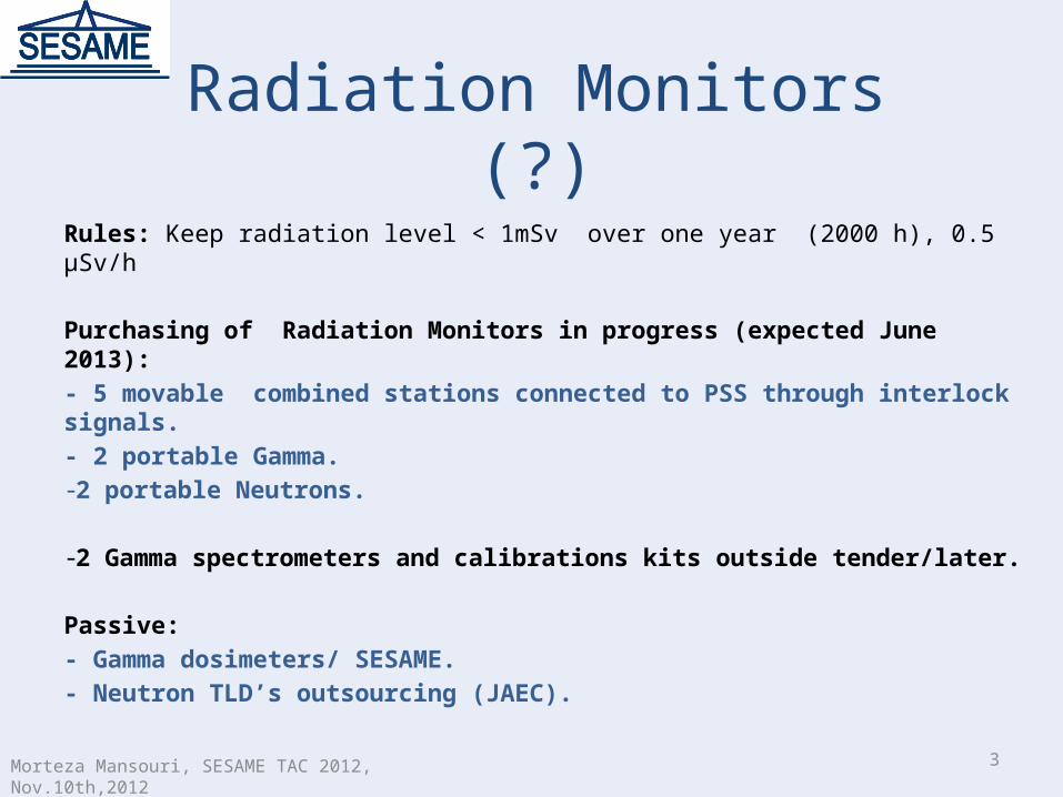
Radiation Monitors (?)Rules: Keep radiation level < 1mSv over one year (2000 h), 0.5 µSv/h
Purchasing of Radiation Monitors in progress (expected June 2013):- 5 movable combined stations connected to PSS through interlock signals.- 2 portable Gamma.-2 portable Neutrons.
-2 Gamma spectrometers and calibrations kits outside tender/later.
Passive:- Gamma dosimeters/ SESAME.- Neutron TLD’s outsourcing (JAEC).
Morteza Mansouri, SESAME TAC 2012, Nov.10th,2012
4Morteza Mansouri, SESAME TAC 2012, Nov.10th,2012
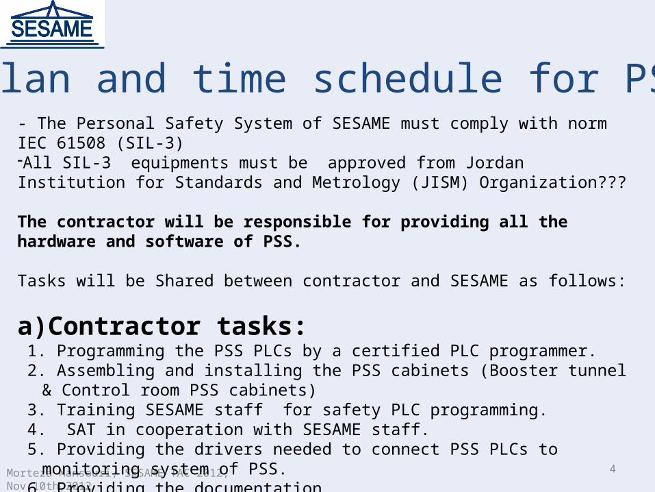
Plan and time schedule for PSS- The Personal Safety System of SESAME must comply with norm IEC 61508 (SIL-3) -All SIL-3 equipments must be approved from Jordan Institution for Standards and Metrology (JISM) Organization???
The contractor will be responsible for providing all the hardware and software of PSS.
Tasks will be Shared between contractor and SESAME as follows:
a) Contractor tasks: 1. Programming the PSS PLCs by a certified PLC programmer. 2. Assembling and installing the PSS cabinets (Booster tunnel & Control room PSS cabinets) 3. Training SESAME staff for safety PLC programming. 4. SAT in cooperation with SESAME staff. 5. Providing the drivers needed to connect PSS PLCs to monitoring system of PSS. 6. Providing the documentation.
5Morteza Mansouri, SESAME TAC 2012, Nov.10th,2012
Plan and time schedule for PSS
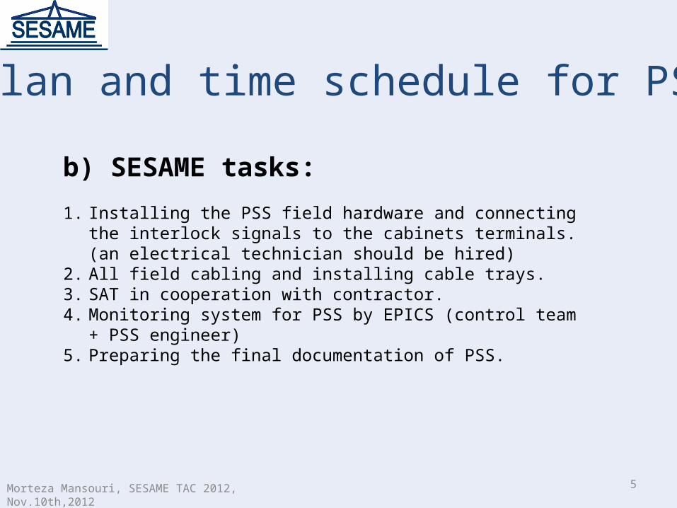
b) SESAME tasks:
1. Installing the PSS field hardware and connecting the interlock signals to the cabinets terminals. (an electrical technician should be hired)
2. All field cabling and installing cable trays.3. SAT in cooperation with contractor.4. Monitoring system for PSS by EPICS (control team + PSS engineer)5. Preparing the final documentation of PSS.
6Morteza Mansouri, SESAME TAC 2012, Nov.10th,2012
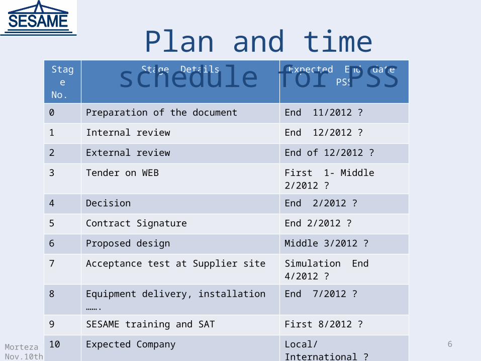
Stage No.
Stage Details Expected End date PSS
0 Preparation of the document End 11/2012 ?
1 Internal review End 12/2012 ?
2 External review End of 12/2012 ?
3 Tender on WEB First 1- Middle 2/2012 ?
4 Decision End 2/2012 ?
5 Contract Signature End 2/2012 ?
6 Proposed design Middle 3/2012 ?
7 Acceptance test at Supplier site Simulation End 4/2012 ?
8 Equipment delivery, installation ……. End 7/2012 ?
9 SESAME training and SAT First 8/2012 ?
10 Expected Company Local/ International ?
11 Warranty 5 years ?
Plan and time schedule for PSS
7Morteza Mansouri, SESAME TAC 2012, Nov.10th,2012
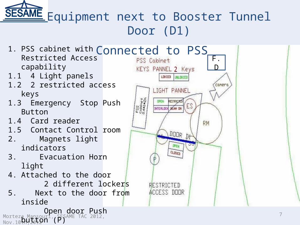
Equipment next to Booster Tunnel Door (D1)
Connected to PSS 1. PSS cabinet with Restricted Access
capability1.1 4 Light panels1.2 2 restricted access keys1.3 Emergency Stop Push Button1.4 Card reader1.5 Contact Control room2. Magnets light indicators3. Evacuation Horn light 4. Attached to the door 2 different lockers5. Next to the door from inside Open door Push button (P)6. Next to the door from outside6.1 Radiation Monitor6.2 Camera7. Fire detector (F.D)
F.D
8Morteza Mansouri, SESAME TAC 2012, Nov.10th,2012
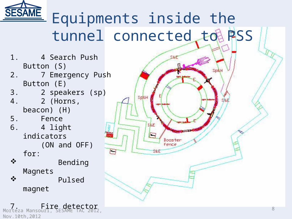
1. 4 Search Push Button (S)2. 7 Emergency Push Button (E)3. 2 speakers (sp)4. 2 (Horns, beacon) (H)5. Fence6. 4 light indicators (ON and OFF) for: Bending Magnets Pulsed magnet
7. Fire detector
Equipments inside the tunnel connected to PSS
9Morteza Mansouri, SESAME TAC 2012, Nov.10th,2012
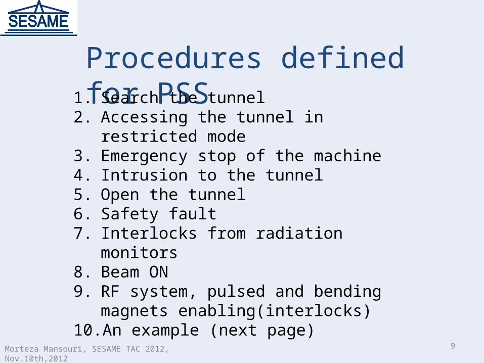
Procedures defined for PSS1. Search the tunnel2. Accessing the tunnel in restricted mode3. Emergency stop of the machine4. Intrusion to the tunnel5. Open the tunnel6. Safety fault7. Interlocks from radiation monitors8. Beam ON9. RF system, pulsed and bending magnets
enabling(interlocks)10. An example (next page)
10Morteza Mansouri, SESAME TAC 2012, Nov.10th,2012
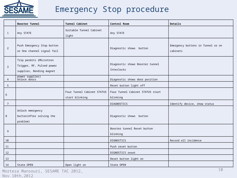
Emergency Stop procedure
Booster Tunnel Tunnel Cabinet Control Room Details
1 Any STATE Suitable Tunnel Cabinet light Any STATE
2Push Emergency Stop button or One
channel signal fail Diagnostic shows button Emergency buttons in Tunnel or on cabinets
3
Trip permits (Microtron Trigger, RF,
Pulsed power supplies, Bending
magnet power supplies)
Diagnostic shows Booster tunnel Interlocks
4 Unlock doors Diagnostic shows door position
5 Reset button light off
6 Four Tunnel Cabinet STATUS start
blinkingFour Tunnel Cabinet STATUS start blinking
7 DIAGNOSTICS Identify device, show status
8Unlock emergency button(After
solving the problem) Diagnostic shows button
9 Booster tunnel Reset button blinking
10 DIGNOSTICS Record all incidence
11 Push reset button
12 DIGNOSTICS reset
13 Reset button light on
14 State OPEN Open light on State OPEN
11Morteza Mansouri, SESAME TAC 2012, Nov.10th,2012
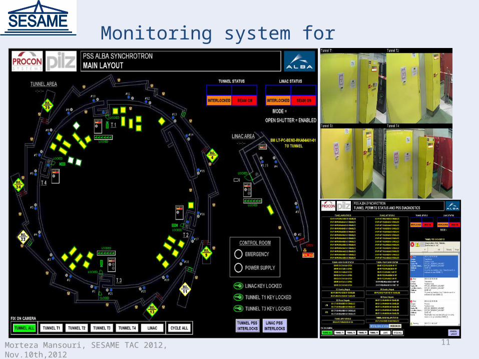
Monitoring system for PSS
12
Acknowledgments:1- Adli Hamad (SESAME)2- David Fernandez (Alba)
Morteza Mansouri, SESAME TAC 2012, Nov.10th,2012

13
THANK YOU FOR YOUR ATTENTION
Morteza Mansouri, SESAME TAC 2012, Nov.10th,2012