SES 405: Exploration Systems Engineering – Class …origins.sese.asu.edu/ses405/Class Notes/Class...
40
Exploration Systems Engineering: Class Review SES 405: Exploration Systems Engineering – Class Review
Transcript of SES 405: Exploration Systems Engineering – Class …origins.sese.asu.edu/ses405/Class Notes/Class...

Exploration Systems Engineering: Class Review
SES 405: Exploration Systems Engineering – Class Review

Exploration Systems Engineering: Class Review 2
Requirements — The Basics
♦ Requirements define the problem to be solved and establish the terms by which mission success will be measured.
♦ Requirements are the single biggest problem in development projects so attention to detail in creating good requirements is vital.
♦ The later a problem is discovered the more costly is the recovery.
♦ Requirements are distributed within the system architecture via flow-down, allocation and derivation.
♦ Requirements traceability is a technique of tracking the source and connections between requirements. It is used to assess the consequences of potential requirements changes.
♦ When a system is decomposed into smaller segments, interfaces are created that must be defined and managed.

Exploration Systems Engineering: Class Review 3
Writing Requirements
♦ Good requirements Are SMART: Specific, Measurable, Achievable, Relevant and Traceable
♦ It is good practice to capture the rationale and preliminary technique for verification when writing requirements.
♦ Requirement validation is a process of ensuring that the set of requirements is correct, complete, and consistent.
♦ Since the cost of reconciling undefined requirements grows as the project matures, undefined (TBD) and estimated (TBR) requirements should be resolved as early as possible.

Exploration Systems Engineering: Class Review 4
The Project Life Cycle
♦ A project is divided into distinct life cycle phases. • Pre-Phase A: Concept studies • Phase A: Concept and technology development • Phase B: Preliminary design and technology completion • Phase C: Final design and fabrication • Phase D: System assembly, test and launch (otherwise known as panic
mode) • Phase E: Operations and sustainment • Phase F: Closeout or disposal
♦ These phases are separated by control gates - typically associated with a major project review, such as preliminary design review (PDR).
♦ Each project phase has a distinct purpose and set of products.
♦ At the end of each phase a new system baseline — or an agreed-to set of requirements, designs, or documents — is established.
♦ A system baseline is the point of departure for the development work in each new phase.

Exploration Systems Engineering: Class Review 5
Major Project Reviews Precede Each Key Decision Point
Key Decision Points
FORMULATION IMPLEMENTATION
Major Reviews
A C
D E
Project Phases
Concept Studies
Concept & Technology Development
Preliminary Design & Technology Completion
Final Design & Fabrication
System Assembly, Test, & Launch
Closeout Operations & Sustainment
A B
B
C
F
D E F Pre-A
Mission Concept Review
Systems Requirements Review
Mission/System Definition Review
Critical Design Review
Systems Integration Review
Operational Readiness Review
Flight Readiness Review Post Launch Assessment Review
Decommissioning
Review
Preliminary Design Review
Independent Cost Estimates

Exploration Systems Engineering: Class Review
The Engineering Activities in the Project Life Cycle
Time and Project Maturity
Mission Requirements
& Priorities
System Demonstration
& Validation
Develop System Requirements &
System Architecture
Allocate Performance Specs & Build
Verification Plan
Design Components
Integrate System & Verify
Performance Specs
Component Integration & Verification
Verify Component Performance
Fabricate, Assemble, Code &
Procure Parts
System Level
Subsystems
Components
A
D C
E
B

Exploration Systems Engineering: Class Review 7
Configuration and Change Management
♦ System baselines capture the complete, current system description.
♦ System baselines are updated periodically at five major milestone reviews - SDR, PDR, CDR, FRR and ORR.
♦ Requirements and configuration changes are inevitable, so a formal process of considering the implications of any changes is mandatory.
♦ It is important to have managed baselines, requirements and configurations so that the entire team is working with the same assumptions of what the current system is, and what it must do.
♦ Systems engineering is responsible for creating and updating the system baseline, assessing the implications of considered changes and disseminating the news of any accepted changes.

Exploration Systems Engineering: Class Review 8
Verification
♦ Validation - Did we build the right system? ♦ Verification - Did we build the system correctly? ♦ Requirements validation - Are the requirements complete,
consistent, SMART and do they capture the intent of the system?
♦ Requirements verification is about establishing confidence that the system will perform in its intended environment.
♦ Requirements are verified by test, demonstration, analysis and inspection.
♦ Space systems go through rigorous ground-based tests that simulate the launch and space environment.
♦ Using heritage designs can save development time and money, but any heritage design should be validated and verified as if it represented new hardware.
♦ Simple procedural errors - like borrowing another project’s bolts - can lead to multi-million dollar (or life threatening) accidents.

Exploration Systems Engineering: Class Review 9
Technical Reviews
♦ Technical reviews are key development milestones used to measure progress, assess project maturity and to infuse lessons from the past. They… • Provide confirmation of completed effort and readiness to commit
additional resources for the next phase. • Encourage and establish project discipline with an integrated
project team perspective. • Identify risks and review mitigation options. • Describe plans and priorities for the next phase.
♦ There are 11 reviews in the minimum set of technical reviews for a NASA robotic mission. These reviews cover the entire mission life — assessing the concepts and designs early; readiness for test, flight and operations in mid-life and plans for disposal at the mission’s end.
♦ These reviews are held to demonstrate that the appropriate products, accomplishments and plans have been completed before proceeding to the next phase. • Appropriate products, accomplishments and plans are based on the
lessons of hundreds of past projects (best practices).

Exploration Systems Engineering: Class Review 10
Schedule
♦ There are different methods for displaying project schedule information.
♦ Gantt and Milestone charts relate activities to calendar dates in an easily understood format.
♦ Network schedules show the dependencies between activities in a graphical portrayal with activity durations.
♦ Critical Path is the sequence of activities that will take the longest to accomplish. Any delay on this path will delay the project. Activities that are not on the critical path have a certain amount of time that they can be delayed until they, too are on the critical path. This time is called float (or slack).
♦ There is inherent risk in developing schedules. Probabilistic techniques can be used to assess the risk.
♦ For space missions, guidelines exist for determining schedule margin.
♦ Schedule information, such as the accomplishment of milestones or the amount of schedule slack, can be used to report project status/progress (as a form of technical performance measures).

Exploration Systems Engineering: Class Review 11
Gantt Chart Format aka Bar Charts
Gantt and milestone charts are best used for displaying the planned activities and events of a project and the progress in meeting them. This makes them very useful for presenting schedule and program status information in a concise simple format at such things as program or activity reviews. Because of its simplicity and ease of interpretation, it is a particularly good tool for communicating to higher management when information must be presented quickly and efficiently.

Exploration Systems Engineering: Class Review 12
RRF-2 ISS-1 RRF-3
First Stage
Jun System Engineering & Integration
Gov’t Lead
ATP SRR PDR CDR Del for RRF3
Del ISS1 to KSC Del for
RRF2
Gov’t Lead SRR PDR CDR MPTA Del for RRF3 Del for
US ISS-1 to KSC Del
for RRF2
Dev Eng Needed CDR Del for
ISS-1 MPTA
Del for RRF-1
Jul Nov Apr Fab, Integ & Test Upper Stage
FY05 FY06 FY07 FY08 FY09 FY10 FY11 FY12
Flight Test/ Mission Milestones
FY13
ISS-2 UCM-1 RRF-1
CEV ATP
Contractor 1&2 SRR Del for
RRF-1
SDR PDR CDR
Del for RRF-2
Del for RRF-3
Del for ISS-1
Del for PC-1
Unpressurized payload structure
Program Integration L1 Req
Baseline Review
L2 SRR Complete
Pre-NAR Kickoff
L2 SDR
Pre-NAR Complete
PDR Complete
CDR Complete
CLV SRR
NAR
PC-1 PC-2 ISS-3
Delivery of Crew & Service Module
Delivery of Launch Abort System
Del for RRF-1
Del for RRF-3
Del for RRF-2
Del for ISS-1
Del for RRF3
Del for RRF2
Example Milestone Chart
LAS-1 LAS-2 LAS-3
LAS-4
Del for LAS-1
Del for LAS-2 Del for LAS-2
Del for LAS-3
Del for LAS-4
Del for LAS-1
Del for LAS-2
Del for LAS-3
Del for LAS-4
CEV SRR
Upper Stage Engine (RS-25d/e)
Jul
CDR
Feb
PDR
ATP SRR PDR
Pre-formulation
Phase B
Phase C/D
Phase A Non-Traditional
= 0% Complete
= 100% Complete

Exploration Systems Engineering: Class Review 13
Scoping & ConOps
♦ The first step in understanding the mission at hand is defining the scope, where scope is a definition of what is germane to your project.
♦ The scope content involves • Defining the needs, goals, and objectives • Identifying stakeholders • Developing operational concepts • Understanding constraints
♦ A thorough scoping effort leads to organized and informed mission and system requirements.
♦ A concept of operations (conops) is a description (often pictorial) of how the system will be operated during the mission phases in order to meet stakeholder requirements.
♦ A concept of operations can include many aspects of operations, such as a timeline, a communications strategy, varying operational scenarios, etc.

Exploration Systems Engineering: Class Review 14

Exploration Systems Engineering: Class Review 15
System Architecture
♦ Creating a system architecture is a systems engineering function that is the first step in translating a defined problem into a solution.
♦ Creating an architecture is a recursive, iterative process that begins with the problem statement, creates some candidate solutions, assesses their merits and chooses one.
♦ Architecture creation is not a deterministic process, but understanding the strengths, weaknesses and adaptability of heritage or analogous systems is a valuable first step.
♦ In working with the stakeholders, the function or performance requirements of the system may be modified to create a better match between the problem statement and the candidate solution.
♦ Like many systems engineering functions, architecting is one of balancing competing factors and choosing a preferred solution with uncertain and sometimes ambiguous information.
♦ No one view captures an architecture. Many views are used to capture the system structure defined in terms of system elements, interfaces, processes, constraints, and behaviors.

Exploration Systems Engineering: Class Review 16
Functional Analysis
♦ Functional analysis is a system development tool used to capture required system functions.
♦ Functional analysis also supports functional decomposition - the process of describing the sub-functions that are necessary for each function.
♦ Functional Flow Block Diagrams (FFBDs) are graphical tools used to capture the functional sequence and functional hierarchy of a system.
♦ Time-Line Analysis (TLA) is a tool used to capture the duration, and sequence of system functions. TLA can be used in conjunction with FFBDs.
♦ Functional analysis is implementation independent. In other words, all functions are describes in terms of what must be done (and sometimes how well) not how it will be done. This independence ensures that when subsequent trade studies choose how functions will be performed they will be unbiased.

Exploration Systems Engineering: Class Review 17
Planetary Defense Level 1 Functional Flow Block Diagram For Threat Detection
1.10 Decide on Ac-on
1. Detect Threat
or
Ref. 2. Eliminate
Threat
Ref. 3. Reevaluate Threat (b)
Ref. 3. Reevaluate Threat (a)
1.1 Coordinate Assets 1.2 Monitor Sky 1.3 Confirm
Sigh-ng(s)
1.4 Determine Composi-on
1.5 Determine Size
1.6 Determine Velocity
1.7 Determine Orbital Elements
1.8 Run Simula-on(s)
1.9 Establish Level of Threat and and
Exploration Systems Engineering: Class Review 18
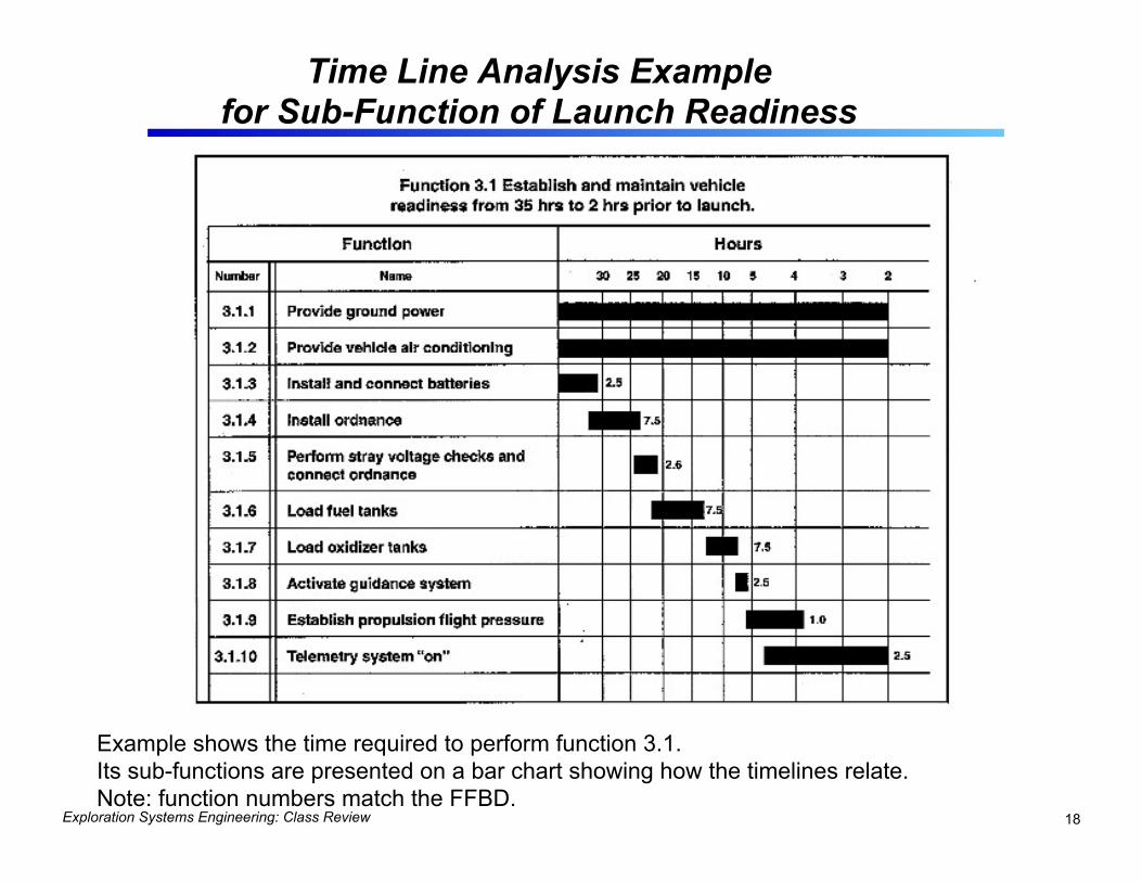
Time Line Analysis Example for Sub-Function of Launch Readiness
Example shows the time required to perform function 3.1. Its sub-functions are presented on a bar chart showing how the timelines relate. Note: function numbers match the FFBD.

Exploration Systems Engineering: Class Review 19
System Design (1/2)
♦ System design produces a physical architecture from the functional architecture.
♦ System design is an iterative process in that many subsystem solutions are considered, and the subsequent system merits are assessed before a baseline is established.
♦ To assess the merits of candidate subsystems, consider their performance, risks, heritage, technical maturity, and limits of their performance.
♦ One way to seek optimal system design is to choose performance and resource allocations to equally stress all subsystems. Share the pain among subsystems.
♦ System requirements define a successful solution. Know when to stop trying to improve a design - better is the enemy of good enough.

Exploration Systems Engineering: Class Review 20
System Design (2/2)
♦ Maintain a decision database and formally review it at each project milestone review.
♦ Use performance-resource (utility) curves to identify break points to help develop balanced solutions.
♦ Determine the ‘driving’ requirements. • Understand which requirements are the toughest to meet
and consider reallocation to manage them. ♦ Subsystems with high cohesion, low complexity and low
connectivity are good. In other words, keep interfaces simple and similar functions together.
♦ In system design decisions, consider robustness — a measure of a system’s sensitivity to environmental or resource variation.
Exploration Systems Engineering: Class Review 21
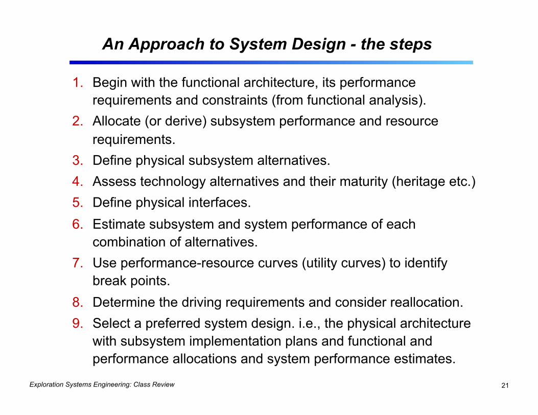
An Approach to System Design - the steps
1. Begin with the functional architecture, its performance requirements and constraints (from functional analysis).
2. Allocate (or derive) subsystem performance and resource requirements.
3. Define physical subsystem alternatives. 4. Assess technology alternatives and their maturity (heritage etc.) 5. Define physical interfaces. 6. Estimate subsystem and system performance of each
combination of alternatives. 7. Use performance-resource curves (utility curves) to identify
break points. 8. Determine the driving requirements and consider reallocation. 9. Select a preferred system design. i.e., the physical architecture
with subsystem implementation plans and functional and performance allocations and system performance estimates.

Exploration Systems Engineering: Class Review 22
Trade Studies
♦ Trade studies are common decision-support tools that are used throughout the project lifecycle to capture and help assess alternatives.
♦ The steps in the trade study process are: 1. Define the objectives of the trade study 2. Review inputs, including the constraints and assumptions 3. Choose the evaluation criteria and their relative importance 4. Identify and select the alternatives 5. Assess the performance of each option for each criteria 6. Compare the results and choose an option 7. Document the trade study process and its results
♦ Trade trees are graphical tools that help manage multi-variable options.

Exploration Systems Engineering: Class Review 23
ISRU No ISRU
Inte
rpla
neta
ry
Prop
ulsi
on
(no
hybr
ids
in
Phas
e 1)
Mar
s A
scen
t Pr
opel
lant
M
ars
Cap
ture
Met
hod
Car
go
Dep
loym
ent
Aerocapture Propulsive
ISRU No ISRU ISRU No
ISRU ISRU No ISRU
Aerocapture Propulsive
ISRU No ISRU
Aerocapture Propulsive
ISRU No ISRU ISRU No
ISRU ISRU No ISRU
NTR
E
lect
ric
Che
mic
al
NTR
E
lect
ric
Che
mic
al
NTR
E
lect
ric
Che
mic
al
NTR
E
lect
ric
Che
mic
al
NTR
E
lect
ric
Che
mic
al
NTR
E
lect
ric
Che
mic
al
NTR
E
lect
ric
Che
mic
al
NTR
E
lect
ric
Che
mic
al
NTR
E
lect
ric
Che
mic
al
NTR
E
lect
ric
Che
mic
al
NTR
E
lect
ric
Che
mic
al
NTR
E
lect
ric
Che
mic
al
NTR
E
lect
ric
Che
mic
al
NTR
E
lect
ric
Che
mic
al
NTR
E
lect
ric
Che
mic
al
NTR
E
lect
ric
Che
mic
al
Aerocapture Propulsive
Pre-Deploy All-up Pre-Deploy All-up
Opposition Class Short Surface Stay
Mis
sion
Ty
pe
Human Exploration Of Mars
Special Case 1-year Round-trip
Top-level Trade Tree-Example for Mars
1 2 3 4 5 6 7 8 9 10 11 12 13 14 15 16 17 18 19 20 21 22 23 24 25 26 27 28 29 30 31 32 33 34 35 36 37 38 39 40 41 42 43 44 45 46 47 48
Œ � Ž � � ‘ ’
“ ” � ‚ • • NTR- Nuclear Thermal Rocket Electric= Solar or Nuclear Electric Propulsion
Conjunction Class Long Surface Stay
Œ 1988 “Mars Expedition”�� 1989 “Mars Evolution”�Ž 1990 “90-Day Study”�� 1991 “Synthesis Group” �� 1995 “DRM 1”�‘ 1997 “DRM 3”�’ 1998 “DRM 4”�“ 1999 “Dual Landers”�” 1989 Zubrin, et.al*�• 1994-99 Borowski, et.al � 2000 SERT (SSP) ‚ 2002 NEP Art. Gravity � 2001 DPT/NEXT M1 2005 MSFC MEPT M2 2005 MSFC NTP MSA
M2 M1 M1 M1
M2 M2 M2 M2
ƒ
Decision Package 1 Long vs Short

Exploration Systems Engineering: Class Review 24
Technology Readiness
♦ The Technology Readiness Level (TRL) scale is used to assign maturity levels to technology considered for space flight.
♦ Low TRLs, or low technology maturity, correlate with development risk.
♦ Early development of enabling, low maturity technologies can reduce the development risk of a system.
♦ JWST attempted to reduce the system development risk by developing some low maturity technologies before PDR, like the primary mirror segments.

Exploration Systems Engineering: Class Review 25
Technology Readiness Levels
Actual system “flight proven” through successful mission operations Actual system completed and “flight qualified” through test and demonstration (Ground or Flight) System prototype demonstration in a space environment System/subsystem model or prototype demonstration in a relevant environment (Ground or Space) Component and/or breadboard validation in relevant environment Component and/or breadboard validation in laboratory environment Analytical and experimental critical function and/or characteristic proof-of-concept Technology concept and/or application formulated
Basic principles observed and reported
Figure 5. Technology Readiness Levels
Basic Technology Research
Research to Prove Feasibility
Technology Development
Technology Demonstration
System/Subsystem Development
System Test, Launch & Operations
Defining TRL = determining what was demonstrated and under what conditions.
Exploration Systems Engineering: Class Review 26
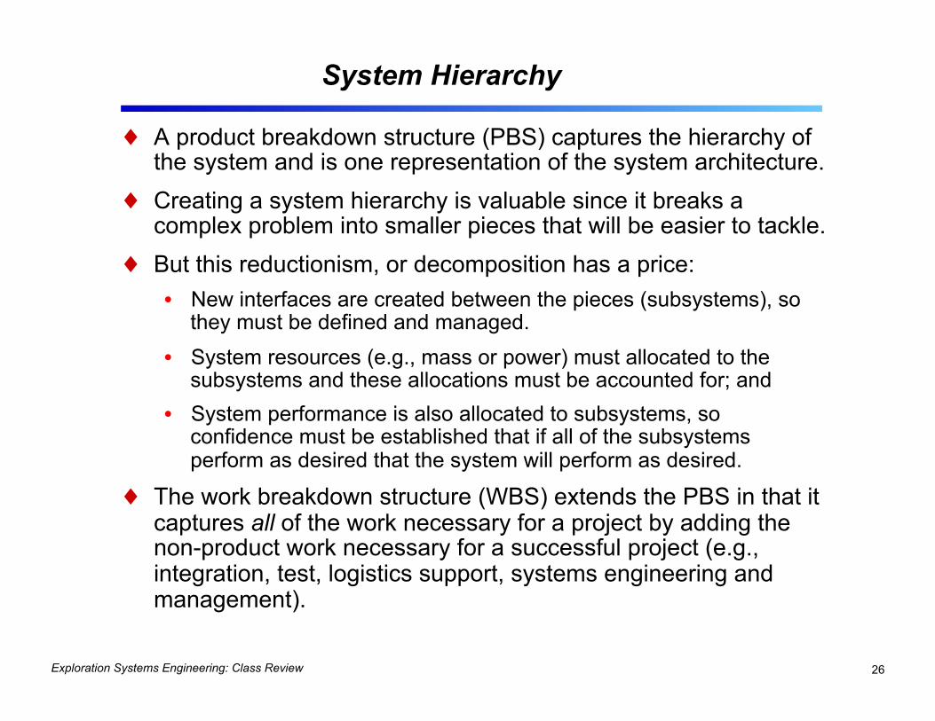
System Hierarchy
♦ A product breakdown structure (PBS) captures the hierarchy of the system and is one representation of the system architecture.
♦ Creating a system hierarchy is valuable since it breaks a complex problem into smaller pieces that will be easier to tackle.
♦ But this reductionism, or decomposition has a price: • New interfaces are created between the pieces (subsystems), so
they must be defined and managed. • System resources (e.g., mass or power) must allocated to the
subsystems and these allocations must be accounted for; and • System performance is also allocated to subsystems, so
confidence must be established that if all of the subsystems perform as desired that the system will perform as desired.
♦ The work breakdown structure (WBS) extends the PBS in that it captures all of the work necessary for a project by adding the non-product work necessary for a successful project (e.g., integration, test, logistics support, systems engineering and management).

Exploration Systems Engineering: Class Review 27
Example: NASA’s SOFIA Project PBS and WBS
Aircraft Element
Telescope Subsystem Electronics Subsystem
Telescope Element
Airborne Facility Science Instruments
Observatory System
Labs/Offices Facility GSE Mission Planning Simulator
Ground Support System
Sofia Project
Management SystemsEngineering
ProjectIntegration &
Test
Operationsand Logistics
Planning
ScienceSupport
MissionAssurance
ObservatorySystem
GroundSupportSystem
Sofia Project
PBS
WBS

Exploration Systems Engineering: Class Review 28
Management
♦ A Project Manager’s roles and responsibilities are different from those of the Project Systems Engineer. The manager is continuously balancing the three project variables of cost, schedule and technical content.
♦ The Project Plan documents the project baseline for implementation. It includes the work breakdown structure, the associated activities, the resources required to accomplish the work, and the planned schedule for completing the work.
♦ The Systems Engineering Management Plan (SEMP) is the project’s guiding technical document. All subordinate technical documents, like a requirements document or test plan, must follow the guidelines of the project SEMP.
♦ Companies and government agencies usually use two different approaches to managing their workforce. In-line management means the responsible workforce directly reports to the project manager. Matrix management means the majority of the workforce is assigned temporarily to a project for a fixed period of time for a specified task.

Exploration Systems Engineering: Class Review 29
Analytical Hierarchy Process
♦ Many decisions are made early in the project life cycle. The decision maker must always choose based on some implicit or explicit evaluation criteria.
♦ The basic steps in the decision making process include: 1. Establish evaluation criteria
2. Establish relative importance of evaluation criteria
3. Develop alternative concepts that meet objectives and top-level requirements
4. Evaluate alternatives relative to the established evaluation criteria
5. The alternative that best satisfies the evaluation criteria represents the tentative concept choice.
♦ Figures of Merit (FOM) is a metric by which a stakeholder’s expectations will be judged in assessing satisfaction with a product or system.
♦ The Analytical Hierarchy Process (AHP) is a methodology that determines “best” through a series of pair-wise comparisons. It can be used to determine attribute weightings as well as alternative scores. • One of the benefits of AHP is the use of a standardized process by which to
compare alternatives. It can be used with both quantitative and qualitative data.

Exploration Systems Engineering: Class Review 30
Interfaces and N2 Diagrams
♦ System external interfaces are defined, distributed and managed like other system requirements.
♦ Internal interfaces, since they are created as the system is decomposed, can be optimized by the development team.
♦ In developing interfaces group like functions, keep them simple and consider the use of standard interfaces.
♦ Since all interfaces run the risk of being ignored as development teams focus on their subsystem responsibilities, explicitly identify the owners of all interfaces.
♦ N-squared diagrams the most common interface identification and management tool. They are are used to: • Capture the existence and nature of an interface • Highlight input and output assumptions and requirements • Demonstrate where there are feedback loops between subsystems • Identify candidate functional allocations to subsystems

Exploration Systems Engineering: Class Review 31
I = Input O = Output
O 1 2 I
O 1 3 I
O 2 3 I
O 1 4 I
O 2 4 I
O 3 4 I
O 2
1 I
O 3
2 I
O 3
1 I
O 4
2 I
O 4
1 I
O 4
3 I
Generic N-squared Diagram as an Interface Artifact
N2 diagram rules: • Items or functions are on
the diagonal
• Items or functions have input and outputs
• Item or function outputs are contained in rows; inputs are contained in columns
Item or
Function 4
Item or
Function 3
Item or
Function 2
Item or
Function 1
External Input (to Item or Function 2)
External Output
(from Item or Function 3

Exploration Systems Engineering: Class Review
Use of Block Diagrams
32
ISIM COMMC&DH
Omni
HGA
MIRI FPE
Ka-Band Modulator
( x2)
Ka-Band TWTA (x 2)
Switches
OTE
EPS
ACS
Reaction Wheels
(x 6)
Propulsion (Bi-Prop )
SecondaryCombustionAugmented
Thrusters(x 4)
MRE -4 STMs(x 8)
Region 1 Region 2 Region 3
Legends :
ISIM 1553 B-I
Spacewire Discrete -pt to pt
Region 1-(within Si /OA ) Region 2-(within IEC )Region 3-(within spacecraft
bus)
WingDeployment Acts
(x 2) &Latch Acts (x8)
Primary Mirror
Secondary Mirror
Tertiary Mirror
photons
Hexapod(6 DOF)
Hexapod(7 DOF )
x18
Primary Power
Fine Sun Sensors (x2)
Wheel Drive Electronics (x6)
Command Telemetry Processor
NIRSpec
FGS
NIRCam
Sunshield
40 Ah NiH 2
Battery
Coarse Sun Sensors (x4)
Valve Drive Electronics (x 2)
Inertial Reference Unit (1)Tower
Actuators
SMSS Deploy
ActActuator
Drive Unit
SunshieldAct (x6)
RS422
Cold Junction
Box
Solid State Recoder
S/C -ISIM 1553 B-SI
Solar Array
Regulators (x2)
Solar Array (3 panels )
(x2)
S/ C 1553 B-S
Telemetry Acquisition
Unit
M otor Switching Relay
Region 3
Analog /Bilevel
Compressor Assembly
Cooling Lines
Radiator Heat Switches
Contn Ctrl Htrs
Cryo Tem p Sensors
MIRI
FGS Guiders FPE /ICE
FGS TF FPE /ICE /TCE
CCE -JT(x2)
CCE -PC(x2)
ISIM Command
& Data Handling
(x2)
IRSU
NIRSpec FPE /ICE /MCE
Star Trackers ( x3)
Solar Array
Act (x2)
High Gain Antenna Act (x2)
Mechanical I /F
DIT CE ( x2)
FSM Act
LVDS
Power Control Unit
S-Band Transponder (x2)
Orientation Drive Electronics with Resolver (x2)
NIRCam FPEs /ICE
MIRI FPE /ICE

Exploration Systems Engineering: Class Review 33
Margins and Contingency
♦ Contingency is the difference between the current best estimate of a resource and its maximum expected value.
♦ A margin is the difference between the maximum possible value of a resource and its maximum expected value, but in some sense is unknowable.
♦ Estimated resource use for a system in development grows as the design matures. Contingency is used to account for this growth, so the project can predict maximum expected values for each resource.
♦ The amount of recommended contingency for a resource is based on historically demonstrated trends and decreases as the design matures.

Exploration Systems Engineering: Class Review 34
Technical Performance Measures ♦ TPMs are measures of the system technical performance that
were chosen because they are indicators of system success.
♦ The trends of past, successful projects are used to create contingency guidelines for new projects.
♦ Tracking TPMs and comparing them against typical resource growth provides an early warning system designed to detect deficiencies or excesses.
♦ TPMs that violate their contingency allocations or have trends that do not meet the final performance should trigger action by the systems engineer.
♦ The final, delivered system value can be estimated by extending the TPM trend line and using the recommended contingency values for each project phase.
♦ There is a balance between contingency for risk management and allocation for design flexibility. This balance is apparent since contingency allocations shrink as designs mature.

Exploration Systems Engineering: Class Review 35
Cost Estimating
♦ Methods for estimating mission costs include parametric cost models, analogy, and grassroots (or bottoms-up). Certain methods are appropriate based on where the project is in its life cycle.
♦ Parametric cost models rely on databases of historical mission and spacecraft data. Model inputs, such as mass, are used to construct cost estimating relationships (CERs).
♦ Complexity factors are used as an adjustment to a CER to compensate for a project’s unique features, not accounted for in the CER historical data.
♦ Learning curve is based on the concept that resources required to produce each additional unit decline as the total number of units produced increases.
♦ Uncertainty in parametric cost models can be estimated using probability distributions that are summed via Monte Carlo simulation. The S curve is the cumulative probability distribution coming out of the statistical summing process.
♦ Cost phasing (or spreading) takes the point-estimate derived from a parametric cost model and spreads it over the project’s schedule, resulting in the project’s annual phasing requirements. Most cost phasing tools use a beta curve.

Exploration Systems Engineering: Class Review 36
Risk
♦ Risk is inevitable, so risks can be reduced but not eliminated.
♦ Risk management is a proactive systematic approach to assessing risks, generating alternatives and reducing cumulative project risk.
♦ Fault Tree Analysis is both a design and a diagnostic tool that estimates failure probabilities of initiators to estimate the failure of the pre-determined, undesirable, ‘top’ event.
♦ Failure Mode Effects Analysis is a design tool for identifying risk in the system design, with the intent of mitigating those risks with design changes.

Exploration Systems Engineering: Class Review 37
A 5x5 Risk Matrix Provides a Quick Visual Comparison of All Project Risks
High risks – mission success jeopardized - immediate action required Medium risk – review regularly – contingent action if does not improve Low risk – watch and review periodically

Exploration Systems Engineering: Class Review 38
Fault tree analysis is a graphical representation of the combination of faults that will result in the occurrence of some (undesired) top event. In the construction of a fault tree, successive subordinate failure events are identified and logically linked to the top event. The linked events form a tree structure connected by symbols called gates.
Fault Tree Analysis

Exploration Systems Engineering: Class Review
Reliability
♦ Reliability is a key attribute of space systems, influencing systems engineering activities such as design, trade studies, modeling, and test.
♦ The reliability function, R(t), is determined from the probability that a system will be successful for at least some specified time.
♦ The Bathtub curve expresses the failure rate as it depends on the age of the system. Early and late in life of the system (similar to the human body) significantly higher failure rates occur called “infant mortality” and “old age” regions. Between these regions normally lies an extended period of approximately constant failure rate. The reliability of systems operating in this region can be simply characterized by an exponential function.
♦ Ways to achieve reliability include fault tolerance, functional redundancy and fault avoidance.
♦ Block diagrams and event trees are useful tools in calculating reliability. An understanding of probability basics is required.

Exploration Systems Engineering: Class Review
General Observations
♦ Requirements, Requirements, Requirements! • Get them right early • Don’t change them
♦ Oversight and Management of Contractors ♦ Human Factors:
• Overwork • The ability to say no • Hopeless optimism
♦ The impact of outside politics ♦ Understand Interfaces, early and often ♦ Never assume anything about heritage ♦ Never underestimate vendors’ greed ♦ Mistakes will happen – be prepared to ‘fess up – it will ensure
mission success
40