Servicing Consumer Microwave Ovens - Diagramasdiagramas.diagramasde.com/otros/MWOBASIC200.pdf ·...
123
Servicing Consumer Microwave Ovens Student Guide Covers 1999 - 2000 models ST-MWO2000
Transcript of Servicing Consumer Microwave Ovens - Diagramasdiagramas.diagramasde.com/otros/MWOBASIC200.pdf ·...

ServicingConsumer
Microwave Ovens
Student GuideCovers 1999 - 2000 models
ST-MWO2000
The microwave oven is made of three basic sections, the magnetron, the highvoltage, and the control section. The intent of this training manual is to explain howeach section operates and cover the troubleshooting techniques required for proper
repair of the Sharp microwave oven line for 1999 - 2000.
CONTENTS
Microwave Oven Basics 1
Microwave Emission Check 19
Microwave Measurement Procedure 20
Magnetron section 22
High Voltage section 27
Control section 30
Sensor circuits 37
Convection section 43
Protection circuits 48
Compu-cook, Compu-Defrost & Express defrost 50
OTR MWO Installation 51
General Service Hints 64
Commonly used parts for 2000 models 75
Commonly used parts for 1999 models 106

Ver SG 9/200 1 Sharp Electronics Corporation
MICROWAVE OVEN BASICS
What Is Microwave Energy?____________________________________________________
When a stone is thrown into a quiet pond, waves are formed which radiate outward fromthe point at which the stone broke the water's surface. There are other kinds of waves thatwe cannot see, but know they exist because we observe their effect. They are knowncollectively under the term radiation, the process of emitting radiant energy in the formof waves or particles.
These waves also radiate outward from the center like the waves on the surface of thepond. They travel, however, at the speed of light, 186,282 miles per second, and carrysmall bundles of energy called photons that vibrate at various frequencies.
There are two basic kinds of electromagnetic radiation:
IONIZING NON-IONIZINGX-rays radio wavesgamma rays microwavescosmic rays infra-red wavesultra-violet rays light waves
IONIZING RADIATION can cause chemical changes to take place with little or notemperature rise.
NON-IONIZING radiation in sufficient intensity will cause a rise in temperature.

Ver SG 9/200 2 Sharp Electronics Corporation

Ver SG 9/200 3 Sharp Electronics Corporation
Radiant waves are characterized by their wavelength and their frequency of vibration(number of complete cycles per second)[Cycle is the change of an alternating waveform from zero to the most positive peak,back to zero, to the most negative peak and back to zero.]
Wavelength x frequency / the speed of light frequency
1 cycle per second = 1 Hertz 1,000 cycles per second = 1 Kilohertz 1,000,000 cycles per second = 1 Megahertz
Thus as the frequency increases the wavelength becomes shorter.Microwaves vibrate millions of times per second (that is, they have a very highfrequency) and are, therefore, very short waves, hence the term microwaves.
There are two microwave frequencies in general use for microwave ovens:
• 915 MHz (wavelength is 32 cm or about 12.5”)• 2450 MHz (wavelength is 12 cm or about 5”)
These are two of the frequencies allocated by the Federal Communications Commission(FCC) for Industrial, Scientific and Medical Use (sometimes called the ISM frequencies).The term MHz stands for megahertz and means millions of cycles per second. The termhertz is used to honor Heinrich Hertz, a German physicist who succeeded in producingand detecting electromagnetic waves, which were later called Hertzian waves.

Ver SG 9/200 4 Sharp Electronics Corporation
In summary, microwave energy consists of bundles of energy vibrating at microwavefrequencies and moving at the speed of light. The effect on material in which they areabsorbed is a rise in temperature.
CLASSIFICATION OF ELECTROMAGNETIC WAVESBAND FREQUENCY WAVELENGTH
VLFVeryLowFrequency
10 KHz100 Km
10 Km
LF LowFrequency
100 KHz1 Km
MF MediumFrequency
1 MHz 100 m
HF High Frequency 10 MHz 10 m
VHFVeryHighFrequency
100 MHz 1 m
UHFUltraHighFrequency (Microwave Oven)
1 GHz 10 cm
SHFSuperHighFrequency
10 GHz1 cm
EHFExtremeHighFrequency
100 GHz 1 mm
INFRARED 10 -3 mm
VISIBLEULTRAVIOLET
106 GHz10 -6 mm
X-RAYGAMMA-RAY
Electromagnetic Wave: 10 KHz - - - 300 GHzMicrowave: 300 MHz - - - 300 GHz
Wavelength: λ = c/f NOTE: c = 3 x 10⁸
Wavelength for Microwave Oven: λ = 12.24 cm Note: f = 2450 MHz

Ver SG 9/200 5 Sharp Electronics Corporation
Microwave energy looses power as it travels through space.Power is lost at a rate that is inversely proportional to
the distance traveled.
____________________________________________________
Microwave Properties____________________________________________________
So far we have mentioned two characteristics or properties of microwave energy:absorption and transmission. Like light waves, microwave energy is also reflected.Metals reflect microwaves and since there is no absorption, metals do no heat. Manymaterials in addition to glass transmit microwaves and again since there is no absorptionthere is no heating. Paper, china and some plastics transmit microwaves and are thereforelikely candidate materials for utensils for use in microwave ovens. The overall result isthat we are able to cook or heat foods in an oven on utensils, which are relatively cool tothe touch. No more burnt fingers.
Reflection
Microwave energy is reflectedfrom metals. Metals do notheat.
Transmission
Many materials transmitmicrowave and do notheat

Ver SG 9/200 6 Sharp Electronics Corporation
____________________________________________________
Advantages of Microwave Oven Heating____________________________________________________
As the conventional heating methods apply heat to the exterior of a substance; dielectricsubstances such as foods, wood, plastics, and rubber are heated unevenly because theyare poor in heat transfer and slow in heat penetration, resulting in a considerabledifferential temperature between the exterior and the interior. Accordingly, the heatingtemperature needs to be increased gradually in a long time if uniform heating is required.Also, much heat is wasted for other substances than the heating object, for example, air,pots, pans and the heat source. Thus the conventional heating is poor in the heatefficiency and also difficult in the adjustment of the heating rate. On the contrary,microwave oven heating has the following advantages.
1. Even Heating: Since the microwave penetrates into substances to some depth,it heats the substances more evenly than the conventional heating methods.
2. Very high heating efficiency and speedy cooking.3. The microwaves do not heat anything other than absorbing materials such as
food.4. Exact Control of Heating Rate: The microwave output is regulated as desired
and the cooking time can be instantaneously set by a timer.5. Heating Substance of any Shape: The microwave can easily penetrate and
scatter into the heating substance of any shape.6. Simple oven construction and easy handling. The controls are very few and
they are solid state.7. Very clean heating system, suitable for foods and pharmacy.
Absorption
Those materials which absorbmicrowaves, are heated. Foodsrank high as microwaveabsorbers.

Ver SG 9/200 7 Sharp Electronics Corporation
____________________________________________________
How Does Microwave Energy Produce Heat?____________________________________________________
All matter is made up of atoms and molecules. Some of these molecules are electricallyneutral, that is they have no electrical charge. Carbon tetrachloride, benzene and paraffinwax are examples of electrically neutral materials and microwave energy will passthrough these compounds as if they weren’t present.Most matter, however, is not electrically neutral, and when an electrical field is appliedthe molecules tend to behave like microscopic magnets and attempt to line up with thefield. However, when the electric field is changing millions of times each second, thesemolecular magnets are unable to keep up because of other forces acting to slow themdown, known as friction. Such forces which restrict their movement may be mechanicalsuch as is the case with ice or solid fats, or viscous as the case with a syrup like molasses.The energy of the microwaves in trying to overcome these forces is converted to heat. Ina sense the material converts the energy to heat, or it might be said that the material heatsitself.

Ver SG 9/200 8 Sharp Electronics Corporation
We physically experience a similar phenomenon when we stand inside before a windowon a cold sunny day. The sun generates energy that is radiated through space to the earth.The rays, mostly infrared, pass though the glass window without heating it. The glass istransparent to them. The window itself is cold to the touch. The molecules of our body,being electrically charged, behave like tiny magnets and convert the sun’s energy to heat,and our body feels warm.
____________________________________________________
How Does Microwave Energy Cook So Fast?________________________________________________
An additional characteristic of microwave energy is its ability to penetrate deeply intofood materials and to produce heat instantaneously as it penetrates. This is in sharpcontrast to conventional heating, which depends on the conduction of heat from thesurface to the inside. Conduction heating can be accelerated only by increasing thesurface temperature and obviously there are limits to this approach if excessiveovercooking of the surface of the food is to be avoided.Measurement of the temperature distribution in an item heated in a microwave ovenreveals another difference. The surface will be usually cooler than an inch or so belowthe surface. This is caused by radiation of heat from the food surface to the coolersurroundings of the microwave oven. It does not happen in a conventional oven becauseof the much higher temperatures in such an oven.
Ver SG 9/200 9 Sharp Electronics Corporation
____________________________________________________
Microwave Power: Its Measurement and Its Meaning____________________________________________________
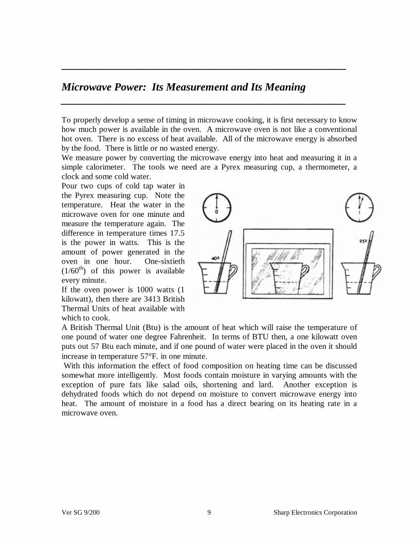
To properly develop a sense of timing in microwave cooking, it is first necessary to knowhow much power is available in the oven. A microwave oven is not like a conventionalhot oven. There is no excess of heat available. All of the microwave energy is absorbedby the food. There is little or no wasted energy.We measure power by converting the microwave energy into heat and measuring it in asimple calorimeter. The tools we need are a Pyrex measuring cup, a thermometer, aclock and some cold water.Pour two cups of cold tap water inthe Pyrex measuring cup. Note thetemperature. Heat the water in themicrowave oven for one minute andmeasure the temperature again. Thedifference in temperature times 17.5is the power in watts. This is theamount of power generated in theoven in one hour. One-sixtieth(1/60th) of this power is availableevery minute.If the oven power is 1000 watts (1kilowatt), then there are 3413 BritishThermal Units of heat available withwhich to cook.A British Thermal Unit (Btu) is the amount of heat which will raise the temperature ofone pound of water one degree Fahrenheit. In terms of BTU then, a one kilowatt ovenputs out 57 Btu each minute, and if one pound of water were placed in the oven it shouldincrease in temperature 57°F. in one minute. With this information the effect of food composition on heating time can be discussedsomewhat more intelligently. Most foods contain moisture in varying amounts with theexception of pure fats like salad oils, shortening and lard. Another exception isdehydrated foods which do not depend on moisture to convert microwave energy intoheat. The amount of moisture in a food has a direct bearing on its heating rate in amicrowave oven.

Ver SG 9/200 10 Sharp Electronics Corporation
One pound of food with 50% moisture will take less time to heat to a specific temperaturethan one pound of food with 75% moisture. Or if both are heated for the same length oftime, the former will reach a higher temperature than the latter. One pound of water,however, will heat only half as fast as one pound of fat. The reason for this requires anexplanation of the term specific heat. This is a measure of a material’s ability to holdheat as compared to water. Water has a value of one (1.0). Fats are about 0.5. Thuswater takes twice as much heat as fat to increase its temperature by one degree.Therefore in our one kilowatt oven, one pound of fat will increase in temperature by114°F, however, the same amount of water will only increase 57°F. (It should be notedthat this does not apply at high temperatures where some of the water may be changed tosteam. This change uses up much more energy.)A simple formula shows the relationship between the heat required and these otherfactors:
“Heat required (BTU) equals Weight (lbs.) times specific heat timestemperature difference (°F.)”
Q = W x s x t
Here’s an example:How long would it take to heat 12 ounces of canned green beans to 160°F. in a onekilowatt microwave oven? The specific heat of most vegetables because of their highmoisture content is around 0.9. Let us assume that the beans would be at an initialtemperature of about 70°F. Q = 0.75? lbs. x 0.9 x (160°F. - 70°F.) Q = 60.75 BTU
Since our oven (1 kW) provided 57 BTU per minute, then the heat required (Q) dividedby 57 BTU/minute would give the time. 60.75/57.0 = about 1 minute 3 seconds
How long would it take if the green beans were just removed from a 40°F. refrigerator?Q = 0.75 lbs. X 0.9 x (160°F. - 40°F.)Q = 81Time = 81/57 = about 1.5 minutes
When two foods at different starting temperatures are heated simultaneously in amicrowave oven the colder food takes longer than the warmer food. An interestingexample is that of apple pie and ice cream. With the pie at room temperature and a scoopof hard frozen ice cream on top, the pie can be warmed without melting the ice cream.About 15 seconds in a 1 kW oven will do the trick.
Ver SG 9/200 11 Sharp Electronics Corporation
____________________________________________________
Browning____________________________________________________
The brown surface color of foods is due to a chemical reaction between food sugars andamino acids, the building blocks of protein foods. This reaction proceeds slowly at lowtemperatures and is accelerated by increasing the temperature. In microwave cooking thesurface temperature of foods rarely exceeds 212°F, the boiling point of water, and isusually much lower. Because of this, most foods cooked in microwave ovens lack thesurface coloration expected of certain foods. A steak or a meat patty, for example, wouldhave a gray unappetizing surface appearance. Baked goods would not have a browncrust. The appearance of such foods can be enhanced by placing them in a hot oven for afew minutes, or in the case of the steak and meat patty, on a grill or under a broiler. Anumber of restaurants which do a sizable steak business pre-sear a quantity of steaks inadvance and finish them in seconds in the microwave when ordered. Some foods, whichbecause of their size take longer to cook in a microwave oven, do take on an acceptablesurface appearance. The presence of surface fats as in beef roasts or roasting chickensand turkeys aid this. These fats reach temperatures above 212°F. and act to accelerate thebrowning reaction.
____________________________________________________
Size Grading____________________________________________________
Since small items cook faster than large items, it is good practice to do all of one size at atime. In baking potatoes, for example, if they are nearly alike in size they will all befinished at the same time. The alternative to size grading is to remove the smaller itemsas they are done and continue to cook the larger items. This requires considerably moreattention.

Ver SG 9/200 12 Sharp Electronics Corporation
____________________________________________________
Food Geometry____________________________________________________
Regular shapes heat more uniformly in a microwave oven. When the shape is irregularthe thin, narrow parts tend to overcook and may be dried out by the time the thicker partsare done. This of course happens in conventional cooking but is less pronounced becausecooking is slower. Where it is possible to control the shape, as for example with a meatloaf or by tying a beef roast into a more cylindrical form, much more uniform results areobtained. Where this is not possible, thin parts may be covered with aluminum foil for apart of the cooking cycle. The same technique can be applied in protecting the wing tipsand legs of roasting chickens and turkeys.
____________________________________________________
Shielding____________________________________________________
This subject was mentioned briefly before, but deserves a more lengthy treatment. Sincemetals reflect microwave energy we can use this phenomenon to advantage in certaincooking operations to restrict heating in certain areas. A good example to illustrate thiseffect is in the cooking of a largebeef roast. First, wrap aluminumfoil over the outer two inches ateach end of the roast and cook for2 to 3 minutes per pound ( in a 1kW oven 20 to 30 minutes for a 10lb. Roast). The roast should beturned at least once during thistime. Remove the foil and cook foran equal period of time, againturning at least once. Remove theroast from the microwave oven, cover and let stand an additional 30 to 45 minutes oruntil a meat thermometer inserted into the center of the roast reads 140-150?F. Shieldingthe roast in this way during cooking will insure a more uniform degree of doneness fromone end of the roast to the other. If a more will done roast is desired, it can be returned tothe oven for an additional 5 to 10 minutes.
Ver SG 9/200 13 Sharp Electronics Corporation
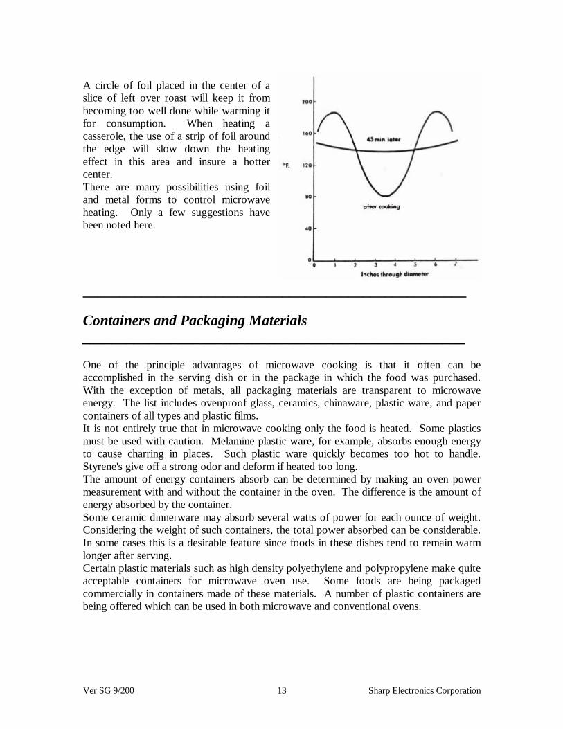
A circle of foil placed in the center of aslice of left over roast will keep it frombecoming too well done while warming itfor consumption. When heating acasserole, the use of a strip of foil aroundthe edge will slow down the heatingeffect in this area and insure a hottercenter.There are many possibilities using foiland metal forms to control microwaveheating. Only a few suggestions havebeen noted here.
____________________________________________________
Containers and Packaging Materials____________________________________________________
One of the principle advantages of microwave cooking is that it often can beaccomplished in the serving dish or in the package in which the food was purchased.With the exception of metals, all packaging materials are transparent to microwaveenergy. The list includes ovenproof glass, ceramics, chinaware, plastic ware, and papercontainers of all types and plastic films.It is not entirely true that in microwave cooking only the food is heated. Some plasticsmust be used with caution. Melamine plastic ware, for example, absorbs enough energyto cause charring in places. Such plastic ware quickly becomes too hot to handle.Styrene's give off a strong odor and deform if heated too long.The amount of energy containers absorb can be determined by making an oven powermeasurement with and without the container in the oven. The difference is the amount ofenergy absorbed by the container.Some ceramic dinnerware may absorb several watts of power for each ounce of weight.Considering the weight of such containers, the total power absorbed can be considerable.In some cases this is a desirable feature since foods in these dishes tend to remain warmlonger after serving.Certain plastic materials such as high density polyethylene and polypropylene make quiteacceptable containers for microwave oven use. Some foods are being packagedcommercially in containers made of these materials. A number of plastic containers arebeing offered which can be used in both microwave and conventional ovens.
Ver SG 9/200 14 Sharp Electronics Corporation
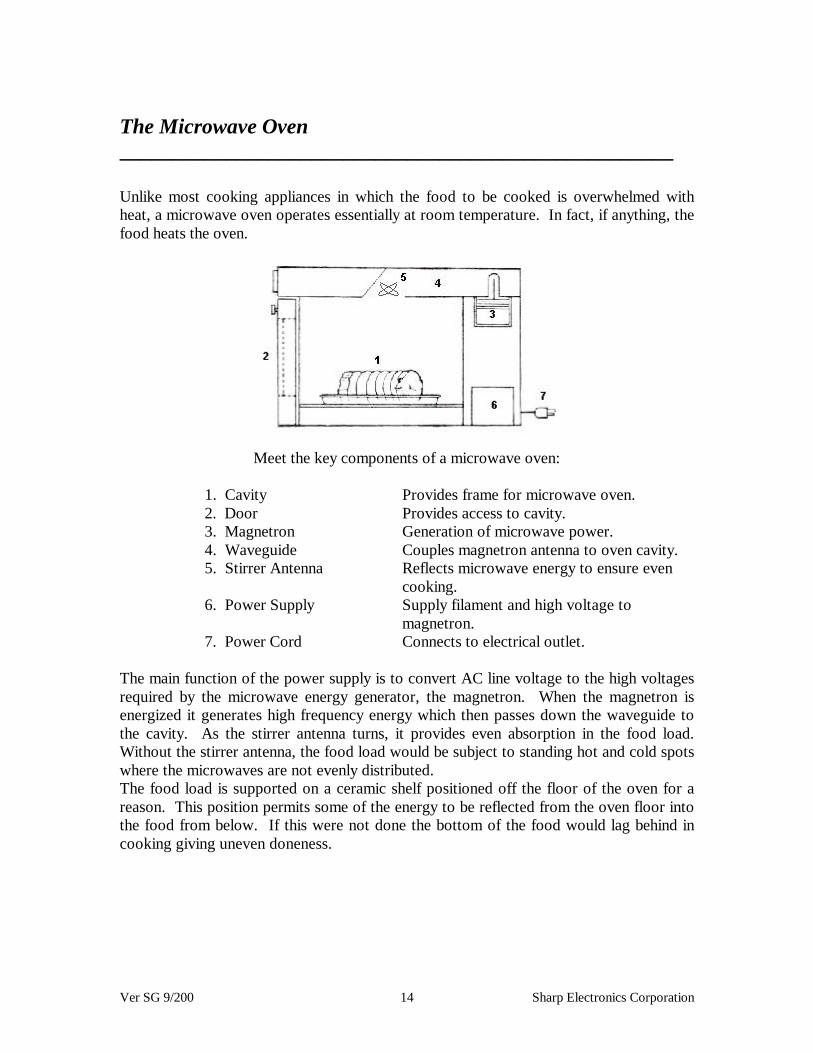
The Microwave Oven____________________________________________________
Unlike most cooking appliances in which the food to be cooked is overwhelmed withheat, a microwave oven operates essentially at room temperature. In fact, if anything, thefood heats the oven.
Meet the key components of a microwave oven:
1. Cavity Provides frame for microwave oven.2. Door Provides access to cavity.3. Magnetron Generation of microwave power.4. Waveguide Couples magnetron antenna to oven cavity.5. Stirrer Antenna Reflects microwave energy to ensure even
cooking.6. Power Supply Supply filament and high voltage to
magnetron.7. Power Cord Connects to electrical outlet.
The main function of the power supply is to convert AC line voltage to the high voltagesrequired by the microwave energy generator, the magnetron. When the magnetron isenergized it generates high frequency energy which then passes down the waveguide tothe cavity. As the stirrer antenna turns, it provides even absorption in the food load.Without the stirrer antenna, the food load would be subject to standing hot and cold spotswhere the microwaves are not evenly distributed.The food load is supported on a ceramic shelf positioned off the floor of the oven for areason. This position permits some of the energy to be reflected from the oven floor intothe food from below. If this were not done the bottom of the food would lag behind incooking giving uneven doneness.

Ver SG 9/200 15 Sharp Electronics Corporation
The purpose of the oven door is to provide an access to the cavity and also to confine themicrowave energy. A proper fitting door is essential to completely confine the energyand, it, as well as the door flange, should be wiped clean regularly to insure good contactof the door and the door flange. Considerable ingenuity has gone into microwave ovendoor design because it is such a critical feature of the oven. A quarter wave slot or“choke” seal around the perimeter of the door acts to choke off or cancel out microwaveemissions at this point.Oven controls consist mainly of a touch pad, microcomputer, function display, interlockswitches and primary (cook) relay. The microcomputer is very accurate so that heatingcycles can be set with a high degree of accuracy. The microcomputer is importantbecause all microwave cooking is gauged by time, not temperature and time.A few extra seconds of cook time in some cases can mean the difference between successand failure. An audio signal usually indicates when the set time has elapsed and the ovenhas turned itself off. The oven may also be turned off simply opening the door. Toprotect the user from unnecessary exposure to microwave energy is a requirement of allmicrowave ovens, and any one of the three interlocks operate when the door is opened,which could turn off the oven.
The Heart of a Microwave Oven
Magnetron & associated parts:
1. Temperature fuse to protect the magnetron against excessive heat.2. Fan motor to force cool air in the magnetron3. Fan duct to direct air stream from the motor.
The magnetron cross-section shows a common twelve-cavity design. Each cavity isresonant at the fundamental frequency of oscillation. As the cathode is heated in a hardvacuum, electrons are “boiled off” accelerated towards the anode by a high voltage(typically -4000 volts) and rotated in a helical path by the magnetic focusing field. Aselectrons boil off, they rotate in clouds, tangential to the cavities, stimulating the build-upof microwave energy in these cavities. As the rotating electrons interact with the fields inthe cavities, they get more strongly focused until “spokes” of electrons are formed, muchlike the spokes of a rotating wheel. When the spokes of electrons, or space charge, rotatesynchronously with the microwave fields of the cavities, the maximum energy is coupledfrom the electrons to the oscillations. Straps connect alternate cavities so that all cavitiesresonate in unison, energy flows up the antenna, and is fed into the cooking cavity.

Ver SG 9/200 16 Sharp Electronics Corporation
Power Transformer:
The filament transformer is of conventional design and supplies 3V to the filament of themagnetron. The high voltage transformer is a unique design and is called a leakagetransformer.
In normal operation, the magnetic flux is induced in the path labeled A (below). Whenexcessive current is drawn the magnetic flux is induce in the path labeled B. This way,any short in the secondary will automatically disable the high voltage section and protectexpensive parts against damage.

Ver SG 9/200 17 Sharp Electronics Corporation
____________________________________________________
Microwave Safety____________________________________________________
Public Law 90-602, the Radiation Control for Health and Safety Act of 1968 was passedby Congress, October 18, 1968. One of the purposes of this law was to establishstandards for various electronic products’ radiation so that the public could not beexposed unnecessarily to excessive amounts of radiation of various kinds given off bythese products. Items such as television sets, sun lamps, microwave ovens and variousother products are covered by this law. Standards for microwave ovens went into effectOctober 6, 1971. Under these standards, radiation leakage from microwave ovens cannotexceed one (1) milliwatt per square centimeter (mW/cm2) measured two (2) inches fromthe oven prior to factory release, and five (5) mW/cm2 thereafter. The measuringequipment to be used is also specified in the standards.Before the standard for microwave ovens went into effect, industry had operated with avoluntary standard 10mW/cm2. Standards were established in order to protecttechnicians working around radar sites from being exposed to possibly dangerous levelsof microwave radiation. Experiments with animals had shown that continuous exposureat relatively high levels of radiation could raise body temperature to a fatal level. The10mW/cm2 standard had a considerable margin of safety built in. This standard for radarworkers was based on what is called “whole body” radiation: that is, conditions underwhich each square centimeter of the body is exposed to radiation. It is said that bodytemperature will rise 1°F. if exposed long enough at this power level. By way ofcontrast, solar energy reaching the Earth on a sunny day may be 60 to 100 mW/cm2.Staring at the sun represents a far greater hazard than exposure to 10 mW/cm2 ofmicrowave radiation. Serious eye damage, even blindness has been known to occur fromimproper observation of a solar eclipse. On the other hand, microwave diathermy at thesame frequency used in microwave ovens is used for treatment of certain eye diseases.The level of energy employed is much greater than 10mW/cm2 and for periods longerthan one would stand in front of a microwave oven. Dr. James Ban Allen, a well knownauthority of radiation technology has expressed the microwave hazard from the operationof a microwave oven, as “about the same as the likelihood of getting a skin tan frommoonlight.” Even the Surgeon General of the United States has publicly stated that noinjuries from microwave oven use have been reported.
Ver SG 9/200 18 Sharp Electronics Corporation
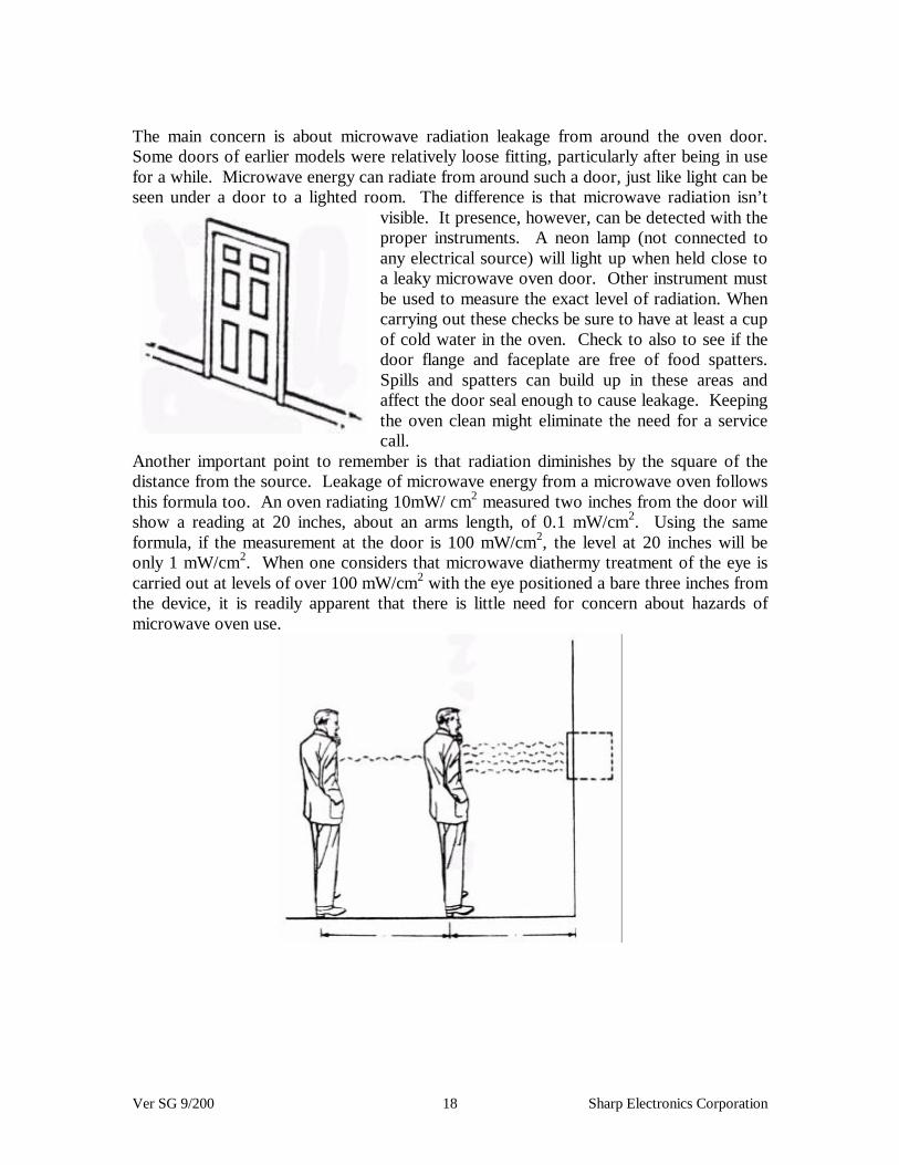
The main concern is about microwave radiation leakage from around the oven door.Some doors of earlier models were relatively loose fitting, particularly after being in usefor a while. Microwave energy can radiate from around such a door, just like light can beseen under a door to a lighted room. The difference is that microwave radiation isn’t
visible. It presence, however, can be detected with theproper instruments. A neon lamp (not connected toany electrical source) will light up when held close toa leaky microwave oven door. Other instrument mustbe used to measure the exact level of radiation. Whencarrying out these checks be sure to have at least a cupof cold water in the oven. Check to also to see if thedoor flange and faceplate are free of food spatters.Spills and spatters can build up in these areas andaffect the door seal enough to cause leakage. Keepingthe oven clean might eliminate the need for a servicecall.
Another important point to remember is that radiation diminishes by the square of thedistance from the source. Leakage of microwave energy from a microwave oven followsthis formula too. An oven radiating 10mW/ cm2 measured two inches from the door willshow a reading at 20 inches, about an arms length, of 0.1 mW/cm2. Using the sameformula, if the measurement at the door is 100 mW/cm2, the level at 20 inches will beonly 1 mW/cm2. When one considers that microwave diathermy treatment of the eye iscarried out at levels of over 100 mW/cm2 with the eye positioned a bare three inches fromthe device, it is readily apparent that there is little need for concern about hazards ofmicrowave oven use.
Ver SG 9/200 19 Sharp Electronics Corporation
MICROWAVE OVEN EMISSION CHECK
Before servicing an operative unit, perform a microwave emission check per theMicrowave Measurement Procedure on page 24 of this manual.
If the microwave emissions level is in excess of the specified limit:
1. Instruct the owner not to use the unit, and
2. Immediately contact SHARP ELECTRONICS CORPORATION @ 1-800-237-4277
Should the unit operate with the door open:
1. Instruct the owner not to operate the unit, and
2. Immediately contact SHARP ELECTRONICS CORPORATION and The Food andDrug Administration’s Center for Radiological Devices and Radiological health.
Service personnel should inform SHARP ELECTRONICS CORPORATION of anycertified unit found with emissions in excess of 4mW/cm2. The owner of the unit shouldbe instructed not to use the unit until the oven has been brought into compliance.

Ver SG 9/200 20 Sharp Electronics Corporation
MICROWAVE MEASUREMENT PROCEDURE
A. Requirements
1) Microwave leakage limit (power density limit): The power density of microwave radiation emitted by a microwave oven should not exceed 1mW/cm2 at any point 5cm or more from the external surface of the oven, measured prior to the acquisition by a purchaser, and thereafter (through the useful life of the oven), 5mW/cm2 at any point 5cm or more from the external surface of the oven.
2) Safety Interlock Switches, Primary interlock relay and door sensing switch shall prevent microwave radiation emission in excess of the requirement as above mentioned, secondary interlock switch shall prevent microwave radiation emission in excess of 5mW/cm2 at any point 5cm or more from the external surface of the oven.
B. Preparation for testing: Before beginning the actual measurement of leakage, proceed as follows:
1) Make sure that the actual instrument is operating normally as specified in its instruction booklet.
2) Place the oven tray in the oven cavity.
3) Place the load of 275 + or - 15 ml (9.8 oz) of tap water initially at 20 + or - (68 degrees F) in the center of the oven cavity. The water container shall be a low form of 600 ml (20 oz) beaker with an inside diameter of approx. 8.5 cm (3 1/2 in.) and made of an electrically nonconductive material such as glass or plastic. The placing of this standard load in the oven is important not only to protect the oven, but also to insure that any leakage is measured accurately.
4) Set the cooking control on Full Power Cooking Mode.
Important:Survey instruments that comply with the requirement for instrumentationas prescribed by the performance standard for microwave ovens, 21 CFR1030. 10(c)(3)(i), must be used for testing

Ver SG 9/200 21 Sharp Electronics Corporation
5) Close the door and select a cook cycle of several minutes. If water begins to boil before the survey is completed, replace it with 275 ml of cool water.
C. Leakage Test Closed -door leakage test (microwave measurement)
1) Grasp the probe of the survey instrument and hold it perpendicular to the gap between the door and the body of the oven.
2) Move the probe slowly, not faster than 1 in/sec (2.5 cm/sec) along the gap, watching for the maximum indication on the meter.
3) Check for leakage at the door screen, sheet metal seams and other accessible positions where the continuity of the metal has been breached (eg. around the switches, indicator, and vents). While testing for leakage around the door, pull the door away from the front of the oven as far as is permitted by the closed latch assembly.
4) Measure carefully at the point of highest leakage and make sure the highest leakage is no greater than 4mW/cm2 (to allow for meter uncertainty), and that the secondary interlock switch does turn the oven OFF before any door movement.
NOTE: After servicing, record data on the service invoice and microwave leakage report.

Ver SG 9/200 22 Sharp Electronics Corporation
MAGNETRON SECTION
In order for the service technician to comprehend the service procedures, and theirlimitations, they must have a understanding of the operation of the magnetron tube.Refer to the next page for the following explanation.
The magnetron is made of a cathode, an anode, and an antenna.
The cathode is made of a substance which will have many free electrons in its molecularstructure. Usually this substance is a man made element which combines barium andstrontium oxide together. Most manufacturers just refer to the oxide coating on thecathode as “rare earth”. The cathode is then encircled with an anode which is constructedto create resonate cavities within its interior. The resonate cavities are then connected toan antenna. The next requirement for manufacturing is to evacuate the air space betweenthe cathode and anode creating a perfect vacuum. A heater is then placed on the cathodewhich shares one of its terminals with the high voltage lead. Magnets are then placedaround the outer side of the anode. The magnetron tube is now ready for operation.
The first requirement for the tube to function requires us to get the free electrons of therare earth element off the cathode, suspending them in the vacuum around the cathode.This is accomplished by pushing current through the heater which is on the cathode. Thecurrent is pushed by a relatively small alternating voltage, usually around 3 volts AC. Asthe cathode heats the electrons begin moving. Much like water is in solid state (ice)when cold, as heat is applied the molecules will begin movement until they actually leavethe mass in the form of steam. We usually refer to the process of electron movementfrom the cathode to the vacuum area as the boiling off process although the electrons donot experience the change of state which we often relate to when we think of boiling.
The next requirement is to get the electron mass to move away from the cathode with acertain degree of velocity. This is accomplished by putting a high voltage charge on thecathode. The charge is usually about 4000 volts negative, direct current. The anode isthen connected directly to ground. The movement of electrons is from negative topositive, the large negative charged electrons see ground as positive which will causethem to accelerate outward toward the anode.
The next step for the tube to operate is the magnetic flux generated from the permanentmagnets on the magnetron, which will restrict the electron movement. The electrons cannot strike the anode directly, they must move past the resonate cavities of the anode. Asthe cloud of electrons pass a cavity they will create movement of the electrons within theanode material (usually a copper alloy).

Ver SG 9/200 23 Sharp Electronics Corporation

Ver SG 9/200 24 Sharp Electronics Corporation
The resonate cavities are so designed that the movement of electrons will be only allowedat the frequency of 2450 MHz. The positive and negative fields created as the cloudpasses one cavity to another will create the pushing and pulling of the electrons all theway to the antenna. As the antenna gets moving within, it will generate electro-magneticenergy, at the frequency of 2450 MHz. This is the RF energy that is used by microwaveovens.
A symptom of a failed magnetron is a no heat complaint. After confirming the powersupply has not failed, unplug the unit and remove the wires from the terminals of themagnetron. With an ohmmeter check the resistance of the heater on the cathode. Thereading should be about .25 Ohms. If the resistance is infinite the heater is open. This ofcourse would not allow the electrons to boil off the cathode surface. Without the cloud ofelectrons in the vacuum area the tube can not generate energy within the resonatecavities. The magnetron would have to be replaced to correct the problem.
Next, with an ohmmeter check from the magnetron terminals to the case of themagnetron. An infinite reading would indicate the tube does not have a cathode to anodeshort. If a short existed between the cathode to anode the electrons would go directly toground, taking the path of least resistance. This of course would again mean the cloud ofelectrons needed within the tube was not present and the tube would not generate energy.Any resistance reading at this point would warrant replacement of the magnetron.
The last test that can be taken on the magnetron is a visual check. Check the magneticrings that are around the anode for a break. If the magnets are broken they will preventthe spherical movement of electrons in the vacuum area of the tube. All the electronswill align themselves up to a North Pole that was developed at the break. Again withoutthe movement of the clouds of electrons past the resonate cavities, the tube will notgenerate energy. The magnetron tube would have to be replaced.
Some failures within the magnetron can not be detected with the use of meters or visualinspections. These types of failures must be diagnosed via process of elimination. Checkall other possible causes for the tube not to operate, if no other reason is detected, replacethe magnetron. An example of this type of failure would be a gassy tube. This conditionoccurs when the vacuum is lost within the tube. The introduction of various gasses willcause friction due to the electrons hitting the electrons from the alien gasses. The heatgenerated from these collisions will super heat the cathode causing deterioration of thecathode. The tube will first emit too much power and the customer will complain of foodover cooking. Then it will very quickly reverse symptoms and have low or no output.This condition of extra heat is usually the reason why the magnets will crack.

Ver SG 9/200 25 Sharp Electronics Corporation
Another failure that can not be easily detected is the weak magnetron. After years ofoperation the amount of electrons that the cathode can release is reduced. The charge thatis carried in the cloud of electrons is diminished and the amount of energy transferred tothe resonate cavities is also reduced. This failure can not be avoided and is in proportionto the amount of time the oven is used. To detect a weak magnetron a running wattagetest must be taken.
During the 1990 product year the microwave industry standardized the ratingspecifications for output power. The ovens prior to 1990 used the 2-liter water loadrating standard . Ovens during 1990 used both the 2-liter method and the new IEC-705test procedure. When you troubleshoot an oven and suspect the magnetron has lowoutput make sure you check the method used to initially rate the oven. If you use the 2-liter method on an oven which was initially rated by the IEC-705 method the output willbe drastically lower. This of course would cause you to replace the magnetron andincorrectly diagnose the trouble.
Due to the complex formula and the precision required to successfully check the output,we recommend you use the following guidelines for testing a suspected weak magnetron.
Power output of the magnetron can be determined by performing a water temperature risetest. This test should only be used if the circuits check good in all the prior ohmmetertests. This test requires a 16-ounce cup and an accurate mercury thermometer. Foraccurate results, the following procedure must be followed carefully:
1. Fill the measuring cup with 16 ounces of tap water and measure the temperature ofthe water with the thermometer. Stir the thermometer through the water until thetemperature stabilizes. Record the temperature of the water.
2. Place the cup of water in the oven, selecting more than 60 seconds of cooking time.
Allow the water to heat for 60 seconds, measuring the time with a stopwatch, secondhand, or digital read out countdown.
3. Remove the cup from the oven and again measure the temperature, making sure to
stir the thermometer through the water until maximum temperature is reached. 4. Subtract the cold water temperature from the hot water temperature. The normal
result should be:15-28 degrees Fahrenheit if testing a 600 watt oven18-33 degrees Fahrenheit if testing a 700 watt oven21-39 degrees Fahrenheit if testing a 850 watt oven22-43 degrees Fahrenheit if testing a 900 watt oven27.7-51.5 degrees Fahrenheit if testing a 950 watt oven34.7-64.6 degrees Fahrenheit if testing a 1000 watt oven32.6-64.6 degrees Fahrenheit if testing a 1100 watt oven
Ver SG 9/200 26 Sharp Electronics Corporation
If the water temperatures are accurately measured and tested for the required time period,the tests results will indicate if the magnetron tube has low power output (low rise inwater temperature), which would extend the cooking time, or a high power output (highrise in water temperature), which would decrease the cooking time. Because cookingtime can be adjusted to compensate for power output, the magnetron tube should not bereplaced unless the water temperature rise test indicates a power output well above orbelow the normal limits.
Test results are only accurate if the power supply line voltage is 120 volts and the ovencavity is clean.

Ver SG 9/200 27 Sharp Electronics Corporation
HIGH VOLTAGE SECTION
The high voltage section of the microwave oven is the section responsible for developingthe voltages required by the magnetron. These voltages are the 3 volts AC and the -4000volts DC. Refer to the graphic on page 29 for the following explanation.
The voltage induction principle of a transformer is used to develop the volts from the 120volt supply. The 3 volts AC is developed on the voltage step down winding which stepsthe voltage down by a 40 to 1 ratio. For every 40 volts applied to the primary windingwe will get 1 volt on the secondary of the step down winding. This winding is oftenreferred to as the filament winding. Due to the induction principle the output of thetransformer must be alternating voltage (AC). This voltage is applied directly across theheating element that heats the cathode surface of the magnetron.
The -4000 volts required to charge the electrons within the magnetron’s vacuum space isdeveloped on the step up winding. This winding steps the voltage up on a ratio of 1 to20. For every 1 volt applied to the primary winding, 20 volts will be developed on thesecondary. On a unit that has 120 volts applied to the primary the output on the highvoltage winding will be about 2400 volts AC. This voltage must now be rectified(converted into DC voltage) and increased. This is accomplished with the use of a siliconrectifier and a capacitor. As the transformer makes its positive and negative swings alongthe sine wave, the rectifier will conduct only during the negative swing. During thisperiod of time the rectifier will totally shunt the magnetron and charge the capacitor.During the positive swing the rectifier will not conduct. This will now give us the 2400volt potential within the secondary winding along with the 2400 volts stored in thecapacitor. The voltage is in series aiding which gives the 4800 volt potential available forthe magnetron.
The voltages referred to in our explanation are not real voltages that you would measureon a working microwave. In practice the voltages may be lower and will vary frommodel to model. The transformer secondary windings are matched to an output rating ofthe magnetron. The size of the capacitor is also matched to the magnetron andtransformer output. The rectifier is current rated for the individual circuit it is used in.Never replace a rectifier, capacitor, transformer, or magnetron with a generic part. Youcan compromise the circuit operation and reliability of the unit.
If you suspect a problem in the magnetron power supply the following test procedureshould be used.
Disconnect the 120 volt power source from the oven (unplug the unit). Discharge thecapacitor. A capacitor is nothing more than a storage device for electricity. Even withthe power disconnected the capacitor can hold a charge of around 2000 volts. Thisvoltage must be discharged to render the unit safe to work on. To discharge thecapacitor, short across the terminals. An arc may occur when the terminals are shorted.This would be a normal situation.

Ver SG 9/200 28 Sharp Electronics Corporation
With an ohmmeter, check the resistance of the primary winding. A normal readingwould be less than one ohm. This reading is hard to detect on an analog meter as theneedle appears to indicate a short. However, if the reading looks close to the shortedcondition and the line fuse is not blown the winding is probably good. Of course, anytime resistance checks are being taken, the component should be isolated (wires removedfrom terminals). This prevents the possibility of putting other resistance’s in parallel withthe component. giving false readings. The secondary is also checked with an ohmmeter.The filament winding should indicate less than one ohm. The high voltage windingshould indicate anywhere from 50 to 200 ohms depending on the output rating of themodel oven you are checking. Be certain to refer to the service manual for the exact ohmreading on the high voltage secondary as layer shorts are the most common problem withpower transformers (the winding reads 90 ohms on your meter but the service manualstates the reading should be 120 ohms, this is a layer short).
The rectifier is also checked with an ohmmeter. Set the analog meter on the X 10,000scale. Place the negative lead of the meter on the cathode of the rectifier (the cathode isthe side to which the arrowhead points toward). A reading of 50,000 ohms is normal. Ifan infinite reading or a low resistance reading is indicated the rectifier is defective.Reverse the leads of the ohmmeter on the rectifier terminals (the negative lead on theanode). This should indicate an infinite reading on the meter, any other reading wouldindicate a defective rectifier.
The capacitor is also checked with an ohmmeter. Isolate the capacitor and place themeter leads on the leads of the capacitor. With the meter set on the X 10,000 scale, theneedle should swing towards a lower resistance reading. As the capacitor charges theresistance should increase to an infinite reading. Reverse the meter leads and the samedeflection should occur as the capacitor now charges with the reverse polarity. If themeter indicates a constant resistance the capacitor is shorted or leaky. If deflection is notpresent it indicates the capacitor is open.
If the transformer, rectifier, and capacitor check good refer to the magnetron section ofthis manual for test procedure.

Ver SG 9/200 29 Sharp Electronics Corporation

Ver SG 9/200 30 Sharp Electronics Corporation
CONTROL SECTION
The controls which are used in microwave ovens vary from oven to oven.
The mechanical timer control is used in models R-200BK, R-200BW, R-300BW and theR-21HC. Refer to the wiring diagram section of this manual for the followingdescription.
The mechanical timer has two basic designs. The first is a simple motor and a singleswitch. The timer dial, when turned, will cause the contacts of the timer switch to close.As the switch contacts close they will complete the parallel circuit to the oven light, fanmotor, turn table motor, timer motor, and power transformer. Once the motor starts toturn it will continue until it mechanically opens the timer switch contacts. This will openthe parallel circuit terminating all oven functions.
To diagnose the mechanical timer, unplug the unit, disconnect the power supply andcheck continuity across the switch contacts. When the timer is in the off position aninfinite reading should be indicated on the meter. When the dial timer is turned to any onposition, zero ohms or continuity should be indicated. If the timer switch checks good,restore power to the unit and turn the timer dial to close the switch contacts. With a voltmeter check for 120 volts across the motor terminals directly. A reading of 120 voltsshould be indicated. If the voltage is present but the timer doesn’t operate, replace thetimer.
The second mechanical timer design has a second switch for the defrost function. Theswitch is normally opened and closed by a cam that turns within the timer assembly. Theswitch is located in series with the power transformer, therefore only affecting thetransformer operation as it opens and closes.
To diagnose the switch the oven must be operating. A voltage check across the defrostswitch must be taken. When the meter indicates 120 volts the switch is open. When themeter indicates zero volts the switch is closed. If the meter fails to detect the switcheither opening or closing, replace the switch and/or the timer assembly depending on thereason for the failure of the switch activation.
All other ovens utilize a solid state control. The control is an assembly which iscomprised of a key unit and a control unit. Refer to the Control Panel Circuit Operationon the next page for the following explanation.

Ver SG 9/200 31 Sharp Electronics Corporation
Ver SG 9/200 32 Sharp Electronics Corporation
Control Panel Circuit
The key unit is a switching device. When a keypad is touched it will momentarily switchan output signal from the microcontroller to the input ports of that same microcontroller.The door sensing switch must be closed and working properly, as this switch isresponsible for enabling the input section of the microcontroller. The input commandwill be recognized by the ROM section of the microcontroller and the desired commandwill be executed.
To diagnose a failure in the key unit, disconnect the mylar ribbon connector between thekey unit and the control unit. With a small diameter solid wire, jump across the keyfunction which has the suspected failure. As an example, if an R-530BK will not clearthe display from the initial “flashing 8” condition, disconnect the ribbon connector andinsert the jumper wire on the control board connector at G1 and G12 (see page 33 forlayout of Key Unit for the R-530BK/BW). Of course the door must be closed and thedoor sensing switch must be operating properly before this test can be made. If a beep isheard and the display clears, the problem would be in the key unit. If the control does notrespond when the jumper connection is made the problem is in the control unit. Any padon the key unit can be tested in this same manner. However, keep in mind themicrocontroller is sequentially programmed. This means certain commands must beentered ahead of others. As an example, the control must first be cleared, the clock set,cooking time entered, and the start key touched. If we try to start the unit before time isentered, the control will not respond.
To diagnose a failure in the control unit, place a voltmeter across the power inputterminals. Refer to the power unit circuit on page 34, model R-530BK. As an example,if the display is dead and the control will not accept commands from the key unit proceedas follows. Place a voltmeter across terminals A-1 and Common on the Power UnitCircuit Board. 120 volts should be indicated on the meter. If zero volts is indicated, theproblem is in the circuitry ahead of the control assembly such as an open monitor fuse.Do not condemn the control if this condition exists. If 120 volts is indicated across A-1and Common further testing is required. With a voltmeter, check across the primarywindings of the low voltage transformer “T1”. The meter should indicate 120 volts. Ifthe voltage is present, the control is not accepting commands, and the display is dead,replace the control assembly. If the meter indicates zero volts across the primary windingof the transformer “T1” but 120 volts was indicated across A-1 and Common, check thefoil pattern between the two test points. When you locate the open foil proceed with therepair procedure on page 35.
Control assemblies for microwave ovens are considered as a replaceable part once thefoil pattern repair is checked.
THIS PROCEDURE MUST BE FOLLOWED PRIOR TO CONDEMNING ACONTROL ASSEMBLY ON ALL THE SOLID STATE CONTROLS FOR THISPRODUCT YEAR.

Ver SG 9/200 33 Sharp Electronics Corporation
KEY UNIT FOR THE R-530BK/BW
G8 G7 G6 G5 G4 G3 G2 G1
G9 5 4 3 2 1 Reheat Popcorn Custom
Help
G10
0 9 8 7 6 BakedPotato
Freshvegetables
KitchenTimer
G11
MinutePlus
CompuDefrost
Fish /seafood
Frozenvegetables
Poultry Groundmeat
PowerLevel
G12
StartTouch
on
Clock Frozensnacks
Beveragecenter
Rice CompuCook
Frozen maindish
StopClear

Ver SG 9/200 34 Sharp Electronics Corporation

Ver SG 9/200 35 Sharp Electronics Corporation
Procedure for repairing an open foil pattern
To protect the electronic circuits, microwave ovens are provided with a fine foil patternin the primary circuit that acts as a fuse. If the foil pattern is open, follow thetroubleshooting procedure as outlined below.
Problem: Power ON, Indicator does not light.
Step Occurrence Cause or Correction
1. Only pattern “a” is Insert jumper wirebroken J1 and solder.
(see page 37)______________________________________________________
2. Patterns “a” and “b” Insert coilare broken RCILF2003YAZZ
between “c” and “d”.
NOTE: At the time of this repair, make a visual inspection of the varistor for burndamage, and test the transformer with an ohmmeter for the presence of a layer short.

Ver SG 9/200 36 Sharp Electronics Corporation
On models which have the liquid crystal display, be sure to check the flex connectorbetween the display and control board. The conductor strip on the board as well as theflex connector must be clean. Any substance, such as grease or dirt, would causeresistance to current flow between these parts and impede the operation of the display.Clean this area with a residue free cleaning agent such as ethyl alcohol. Also inspect thecontrol for a crack or break in the area where the mounting screws hold the assembly intothe frame. If the contact between the board and flex connector is not tight the displaywill not function or will function erratically.
The function of audible signal elimination, will allow the consumer to turn off the buzzer.The Demonstration mode, will allow the consumer to run through a cooking sequence atten times the normal speed without turning on the power circuits. The Child lock, willallow the consumer to disable their control panel to prevent unwanted oven operation
Refer to the “owners guide”, not the service manual, for the specific model you areworking on to determine what features the unit has and the correct procedure used toactivate and deactivate the feature.
The Child Lock prevents unwanted oven operation such as by small children.The oven can be set so that the control panel is deactivated or locked.Should a pad be touched, Lock On will appear in the display.
Eliminates the audible signal when any of the pads are pressed.
The consumer can use the demonstration mode to demonstrate different features withoutpower being applied to the high voltage section.
NOTE: Refer to the owners manual for the model you are working on for the correctprocedure to activate and deactivate the above feature.
Child Lock
Audible Signal Elimination
Demonstration Mode

Ver SG 9/200 37 Sharp Electronics Corporation
SENSOR CIRCUITS
Sensors used in microwave ovens are considered peripherals of the control assembly.They are responsible for sending information back to the microcontroller, which in turnsets the conditions for the microcontroller to turn power on or off to the select circuits.The following is a list of sensors used.
Door Sensing and Secondary Interlock Switches:The secondary interlock switch is mounted in the lower position of the latch hook and thedoor sensing switch in the primary interlock system is mounted in the upper position ofthe latch hook. They are activated by the latch heads on the door. When the door isopened, the switches interrupt the power to all high voltage components. A cook cyclecannot take place until the door is firmly closed thereby activating both interlockswitches. The primary interlock system consists of the door sensing switch and primaryinterlock relay located on the control circuit board.
Thermal Cut-Out (Magnetron):This thermal cut-out protects the magnetron against overheating. If the temperature goesup higher than 257 degrees F (R-820BK/BW) because the fan motor is interrupted or theventilation openings are blocked, the thermal cut-out will open and line voltages to thehigh voltage transformer will be cut off and the operation of the magnetron will bestopped. The thermal cut-out will not resume.
Thermal Cut-Out (Oven):The thermal cut-out located on the top of the oven cavity is designed to prevent damageto the oven if the food in the oven catches fire due to over heating produced by impropersetting of the cooking time. Under the normal operation, the oven thermal cut-outremains closed. However, when abnormally high temperatures are reached within theoven cavity, the oven thermal cut-out will open at 338 degrees F (R-820BK/BW) causingthe oven to shut down. The thermal cut-out will close in at 311 degrees F (R-820BK/BW).
Absolute humidity sensor (AH sensor):This sensor detects humidity or steam generated from the food load. The microcontrollermonitors voltage across two thermistors. One thermistor is in a sealed chamber and theother is open to air. This sensor is located in the rear exhaust vent and relies on theventing system of the oven to blow air across it. As humidity builds up on the sensor inthe open air, it will begin to evaporate, which cools the thermistor. When a voltagedifference is developed across the two thermistors, the microcontroller will calculate theremainder of the cooking time. Refer to pages 39-41 for proper test procedures.

Ver SG 9/200 38 Sharp Electronics Corporation
Oven temperature thermistor:This sensor is used in ovens that have convection heat, The thermistor will changeresistance as the oven temperature increases. The microcontroller will compare thevoltage across the thermistor to the programmed voltage within the ROM. When the twoare equal, the convection heater will be turned off. Refer to page 42 for the proper testprocedure.
Damper switch:This sensor monitors the position of the damper door on ovens that have the convectioncooking feature. The damper door must be closed for convection cooking and open forthe microwave mode. A signal is developed across the damper switch that is converted toeither a logic high (when the switch is open) or a logic low (when the switch is closed).Refer to the convection oven section of this manual for more information on thiscomponent.
Ver SG 9/200 39 Sharp Electronics Corporation
AH Sensor Test
Checking the initial sensor cooking condition:
1. The oven should be plugged in 5 minutes (R-530BK/BW) prior to sensor cooking.2. Room temperature should not exceed 95 degrees F (35 degrees C).3. The unit should not be installed in an area where heat and steam are generated.4. Exhaust vents are provided on the back of the unit, do not block these vents, space is
needed for air circulation.5. Be sure the exterior of the cooking container and the interior of the oven cavity are
dry. Wipe off any moisture with a dry cloth.6. The sensor works with food at normal storage temperatures. Example: chicken
should be at refrigerator temperature, canned soup should be at room temperaturewhen cooking cycles are started.
7. Avoid using aerosol or cleaning solvents during the test as the sensor will detect thevapor and turn off the oven before the food is properly cooked.
8. If the sensor has not detected any vapor from the food load after 30 minutes,“ERROR” will appear in the display and the oven will shut off.

Ver SG 9/200 40 Sharp Electronics Corporation
Testing method for the AH Sensor
To determine if the sensor is defective, the simplest method is to replace it with a newsensor.
1. Disconnect the oven from the power line and remove the outer cabinet.2. Discharge the high voltage capacitor.3. Remove the AH sensor.4. Install the new AH sensor.5. Re-install the outer cabineta) Fill approx. 200 milliliters (7.2 oz) of tap water in a1000 milliliter measuring cup.b) Place the container on the center of tray in the oven cavity.c) Close the door.d) Touch reheat pad once and touch the Start pad.e) The control panel is in automatic Sensor operation.f) The display will start to count down the remaining cooking time, and the oven will
turn off automatically after the water is boiling.If new sensor does not operate properly, the problem is with the control unit.

Ver SG 9/200 41 Sharp Electronics Corporation
Water load cooking test
Oven must be plugged in at least 5 minutes (R-530BK) prior to the test. The cabinetmust be installed and all screws must be tightened.
1. Place approx. 200 milliliters (7.2 oz) of tap water in a1000 milliliter cup.2. Place the cup in the center of the oven cavity.3. Close the door.4. Touch Reheat pad once and touch the Start pad. Now the oven is in sensor cooking
condition and “REHEAT” “SENSOR” and “COOK” will appear in the display.5. The oven will operate for the first 16 seconds, without generating microwave energy.6. NOTE: ERROR will appear if the door is opened or STOP/CLEAR pad is touched
during first stage of sensor cookingAfter approximately 16 seconds, microwave energy is produced, and the display shouldstart to count down the remaining cooking time and the oven should turn off after water isboiling. If the oven does not turn off, replace or check AH sensor or check the controlunit.

Ver SG 9/200 42 Sharp Electronics Corporation
Thermistor Test
1. Disconnect the power supply cord and then remove outer case.2. Open the door and block it open.3. Discharge high voltage capacitor.4. Disconnect connector-D from the control unit. Measure the resistance of thethermistor with an ohmmeter. Connect the ohmmeter leads to Pin #’s D1 and D3.
Room Temperature Resistance68 degrees F - 86 degrees F Approx. 293k ohms - 184k ohms
5. If the meter does not indicate above resistance, replace the thermistor.6. Reconnect all leads removed from components during testing.7. Reinstall outer case cabinet.

Ver SG 9/200 43 Sharp Electronics Corporation
CONVECTION CIRCUITS
The R-820BK/BW combines the microwave and convection cooking modes together.
The convection process requires air to be circulated around a heater within an enclosedoven cavity. When the food load is placed within the confines of the cavity, it will alsobe subjected to the circulating hot air. This will cause the food load to be cooked moreevenly, quicker, and retain the foods natural juices better than the conventional radiantmethod.
The cavity for a micro/convection oven differs from the straight microwave oven. Thecavity must be insulated to retain the hot air within. A heat chamber is added whichincludes the heating element, a thermistor to detect oven temperature, and a convectionfan assembly. The cavity must also have a means to block the vent system, which is usedto vent the oven cavity while in the microwave mode. The means to do this is a damperdoor and switch assembly. The damper assembly is not used in the R-820BK/BW.However, the damper assembly is explained so the technician will become familiar withit.
When the convection mode is selected, the microcontroller will close relays to the heatingelement, convection fan, and oven light. The microcontroller will also monitor thevoltage and/or logic levels on the pins leading to the damper switch and oven thermistor.If the damper switch does not go to the proper logic level for the mode selected (high formicrowave cooking and low for convection cooking) within a specified time the ovenwill shut down. If the oven does not detect a voltage change across the oven thermistorwithin a specified time the oven will again shut down. These two features are designedsafety features within the microcontroller. Refer to page 45 for a detailed explanation ofthe damper assembly.
As the oven continues to operate in the convection mode, the air temperature increases.The oven thermistor, which has a negative temperature coefficient, will decrease inresistance. This will cause the voltage being monitored by the microcontroller todecrease, cycling the relay to the heating element. As the oven cavity cools thethermistor will also cool. This will increase the temperature going to the microcontrollerand cycle the relay back on. This cycling will continue throughout the programmedcooking time.
To check the temperature circuit several factors must be considered. Due to the fact thatthe air flow pattern is a recirculating system, the heater assembly must remain fairlyairtight. If cool room air is allowed to enter the air flow system, the oven temperaturewill always be low and take a long time to reach preheat conditions. Check for air gapsin the area around the heater box and also by the damper door assembly.

Ver SG 9/200 44 Sharp Electronics Corporation
Another factor which will affect the temperature circuit is the line voltage. If the voltageis decreased the wattage output of the heating element will also be decreased.
Fire Sensing Feature (Microwave Mode)The model R-820BK/BW incorporates a sensing feature which will stop the oven’soperation if there is a fire in the oven cavity during microwave cooking.
This is accomplished by the LSI repeatedly measuring the voltage across the temperaturemeasurement circuit (thermistor) during it’s 32-seconds time base comparing theobtained voltage measurements. If the most recent voltage measured is 700mV greaterthan the previous voltage measured, the LSI judges it as a fire in the oven cavity andswitches off the relays to the power transformer, fan motor, oven lamp and turntablemotor. The LSI also stops counting down. Please refer to the following section for amore detailed description.
OperationPlease refer to the timing diagrams below1. The thermistor operates within a 32-seconds time base and it is energized for three (3)seconds and off for 29 seconds. Two (2) seconds after the thermistor is energized, thevoltage across the temperature measurement circuit is sampled by the LSI and twenty one(21) seconds after the thermistor is cut off the LSI turns on the cooling fan for six (6)seconds.2. The above procedure is repeated.. If the difference between the first voltage measured(in step 1) and the voltage measured when the procedure is repeated (step 2) is greaterthan 700mV the LSI makes the judgement that there is a fire in the oven cavity and willswitch off the relays to the power transformer, fan motor, oven lamp and turntable motor.The LSI also stops counting down.3. Once the fire sensor feature has shut the unit down, the programmed cooking cyclemay be resumed by pressing the “START” pad or the unit may be reset by pressing the“CLEAR” pad.
Ver SG 9/200 45 Sharp Electronics Corporation
Damper Open-Close MechanismBelow is a description of the Damper -Close Mechanism that is used in some convectionmicrowave ovens.
The Damper is usually open except during convection cooking. The Damper position isset automatically by the damper motor, motor cam, and damper shaft. These componentsare operated by a signal that is determined by whether microwave or convection cookinghas been selected at the control unit.
MicrowaveThe damper is in the open position because a portion of the cooling air is channeledthrough the cavity to remove steam and vapors given off by heating foods. It is thenexhausted at the top of the oven cavity into a condensation compartment.
Convection CookingThe damper is closed preventing hot air from escaping the oven cavity.
Damper Operation1. When power is applied:
1.1 A signal is sensed in the control unit, operating the shut-off relay.1.2 Contacts of the shut -off relay close, damper motor energizes, damper door opens.1.3 When damper door is moved to open position by damper cam, damper switch is closed (ON Position).1.4 The signal from the damper switch is re-sensed by the control unit, and the shut-off relay is turned off.1.5 The 120 volts to the motor is shut off.
2. When the oven is cooking in the microwave mode, the damper is in the open position.
3. When the oven is in the convection mode:3.1 The damper is energized by touching the convection, temperature, and start pads.3.2 When the damper is in the closed position (damper switch OFF), it’s signal is sensed by the control unit and the shut off relay is de-energized.3.3 The damper is held in the closed position during convection cooking.3.4 At the end of the convection cook cycle, the shut relay is energized and the damper returns to the open position.
NOTE: If the damper door is not in the proper position (Open for microwave cooking,closed for convection cooking), the control unit stops oven operation after 1 minute.

Ver SG 9/200 46 Sharp Electronics Corporation

Ver SG 9/200 47 Sharp Electronics Corporation
Checking Temperature in the Convection Mode
The following test procedure should be carried out with the microwave oven in afully assembled condition (outer case fitted).
It is difficult to measure the exact temperature in the convection oven. An accuratethermocouple type temperature tester must be used. A low priced bi-metal thermometeris not reliable or accurate. The temperature should be checked with the outer case cabinetinstalled, approximately 5 minutes after preheat temperature is reached (audible signalsounds four times). The temperature experienced may be approximately 30 degrees Fmore or less than indicated on the display, however, in most cases the food cookingresults will be satisfactory.
Difference in power supply voltages will also affect the oven temperature. Thehousehold power supply voltage may sometimes become lower than the rated (120V) andcause under-cooking. If the power supply voltage is 10% lower than the rated voltage,longer cooking time is required by 10% to 20%.

Ver SG 9/200 48 Sharp Electronics Corporation
PROTECTION CIRCUITS
Several protection circuits are used in microwave ovens. Besides the sensor shut downcircuits mentioned previously, monitor switches and temperature fuses are also used.
The monitor switch circuit is designed to prevent the oven from energizing any circuit ofthe oven while the door is open. It is also designed to immediately interrupt all circuits ifthe door opens while the oven is in operating mode. The circuit contains a combinationof two switches and a relay on the control assembly. In the models that have mechanicaltimers, a three switch combination is used.
The mechanical timer ovens have the three switches mounted on the door latch assembly.The primary switch monitors the hot side of the power line while the secondary switchmonitors the neutral side. These switches are both normally open switches and will closewhen the door latch hook energizes them. The monitor switch is a normally closedswitch and will open when the door latch energizes it. When the door is closed, theswitches must be so aligned that the monitor switch is energized first. Now that themonitor switch is open the primary and secondary switches can close allowing current topass to the remaining circuits of the oven. If the switches are out of alignment or amechanical problem exists with the door, the monitor switch will remain in the normallyclose position. When the primary and secondary switches close, a dead short will beplaced across the line via the three switches. This, of course, will result in the monitorfuse opening. If the monitor fuse is open due to a failure in the door switches, it isrecommended that all three switches be replaced. This is due to the amount of currentthat will pass through the switch. Even though the amount of time that the current passesthrough the switch contact can be measured in microseconds, it is enough time to dopermanent damage to the switch contacts.
Ovens that use the solid state controls have two switches and a relay for the protectcircuit. While the monitor and secondary switch function the same as in mechanicaltimer models, the primary switch has been replaced by the primary interlock relay. Theinterlock relay has the same function as the primary switch. This relay is activated by thedoor sensing switch and again controlled by the door latch assembly. If a monitor fuse isopen due to a door problem, replace the monitor and secondary switch. It is notnecessary to replace the control assembly or primary relay on the control. This due to theconstruction of the relay. It is capable of carrying the heavy current load where as theswitch is not.
It is easy to see the importance of ordering the correct switch. The monitor switch isnormally closed and the interlock switches are normally open.
Ver SG 9/200 49 Sharp Electronics Corporation
The other protection circuits used in microwave ovens are thermal fuses and thermalcutouts. These devices open when they are exposed to high temperatures. They are usedto monitor the temperatures of the oven cavity and magnetron and will interrupt currentflow to the oven circuits when open. Thermal cut outs will reset after cooling down totheir temperature, but temperature fuses remain open.
In some models, thermal cut outs which have a very low reset temperature are used.These thermal cut outs will not reset after cooling down to room temperature and shouldbe replaced after the cause of the over heating condition has been repaired.
The oven temperature fuse will open if the oven cavity gets too hot, as is the case of afood fire. The magnetron temperature fuse will open if the magnetron overheats due toan abnormal condition such as component malfunction or if the cooling fan becomesinoperative.

Ver SG 9/200 50 Sharp Electronics Corporation
Compu-Cook, Compu-Defrost & Express Defrost
Compu-cook, Compu-defrost & Express defrost are recipes programmed in themicroprocessor. These recipes are three stages of cook time/power level combinationsand were determined by actual test cooking of the foods on the menus. Each food has itsown-programmed recipe, which may differ from model to model. The following pagescontain tables, which have examples of cooking programs according to the model oven.Express & Compu defrost tables precede the compu-cook table.
To troubleshoot an oven with a compu-cook or compu-defrost complaint the followingprocedure should be followed.
Check the oven cavity to insure it is clean. If food and or grease is allowed to build upwithin the oven cavity it will reduce the energy available to heat the food load.
Check the supply voltage going to the oven. For every volt that is down from the ratedvoltage requirement, a 10 watt power loss will be experienced. Compu-cook and compu-defrost rely on time calculations and will be the same regardless of power output.
Check the power output of the magnetron (using one of the methods described in themagnetron section of this manual). A indication of + or – 10% would requirereplacement of the magnetron tube.
Check to confirm the timing cycle for the recipe is correct. Refer to the service manualfor the model you are working on.
If all of the above checks prove good then the trouble is a customer-related problem.Perhaps the customer is guessing at weights or trying to cook quantities greater than therecipe allow. Perhaps the customer is not following the recipe and not stirring when theyshould or not covering the food when advised by the control. Perhaps the customerprefers their food cooked more or less than the way the oven was programmed to cookthat particular food. The list of customer related problems could go on and on. Theprobability of the control miscalculating time is almost nil. Most of all compu-cook orcompu-defrost trouble will be found in:
1) Customer related problems2) Unclean oven cavities3) Low line voltage4) Weak magnetron tubes

Ver SG 9/200 51 Sharp Electronics Corporation
SHARPCarousel
OVER THE RANGE MICROWAVE OVEN/HOOD SYSTEM
INSTALLATION INSTRUCTIONS
Please read all instructions thoroughly before installing the Microwave Oven/HoodSystem. Two people are recommended to install this product.If a new electrical outlet is required, its installation should be completed by a qualifiedelectrician before the Microwave Oven/Hood is installed. See step 3, ELECTRICALGROUNDING INSRUCTIONS1. MOUNTING SPACE
This Microwave Oven/Hood requires amounting space on a wall as shown inFigure 1. It is designed to be used withstandard 12-inch wall cabinets.
If the space between the wall cabinets is 36or 42 inches a Filler Panel Kit can be usedto fill the gap. The metal filler panels comein pairs, each either 3 or 6 inches wide. Seepage 8 for ordering information. The FillerPanel Kit should be installed before theMicrowave Oven/Hood is installed
Fig 1

Ver SG 9/200 52 Sharp Electronics Corporation
2. WALL CONSTRUCTION
This Microwave Oven/Hood should bemounted against and supported by a flatvertical wall. The wall must be flat for properinstallation. If the wall is not flat, use spacersto fill in the gaps. Wall construction shouldbe a minimum of 2" x 4" wood studding and3/8" or thicker dry wall or plaster/lath. Themounting surfaces must be capable ofsupporting weight of 110 pounds— the ovenand contents— AND the weight of all itemswhich would normally be stored in the topcabinet above the unit.
The unit should be attached to a minimum ofone 2" x 4" wall stud. To find the location ofthe studs, one of the following methods maybe used:
A. Use a stud finder, a magnetic device which locates the nails in the stud.
B. Use a hammer to tap lightly across the mounting surface to find a solid sound. Thiswill indicate stud location.
The center of the stud can be located by probing the wall with a small nail to find theedges of the stud and then placing a mark halfway between the edges. The center of anyadjacent studs will normally be 16" or 24" to either side of this mark.
3. ELECTRICAL GROUNDING INSTRUCTIONS
This appliance must be grounded. This oven is equipped with a cord having a groundingwire with a grounding plug. It must be plugged into a wall receptacle that is properlyinstalled and grounded in accordance with the National Electrical Code and local codesand ordinances. In the event of an electrical short circuit, grounding reduces risk ofelectric shock by providing an escape wire for the electric current.
WARNING - Improper use of the groundingplug can result in a risk of electric shock.The oven is equipped with a 3-pronggrounding plug. DO NOT UNDER ANYCIRCUMSTANCES CUT OR REMOVETHE GROUNDING PIN FROM THEPLUG.
Ver SG 9/200 53 Sharp Electronics Corporation
The Power Supply Cord and plug must be connected to a separate 120 Volt AC, 60 Hz,15 Amp, or more branch circuit, single grounded receptacle. The receptacle should belocated inside the cabinet directly above the Microwave Oven/Hood Ground ~ mountinglocation.
NOTE:1. If you have any questions about the grounding or electrical instructions, consult a
qualified electrician or serviceperson.2. Neither Sharp nor the dealer can accept any liability for damage to the oven or
personal injury resulting from failure to observe the correct electrical connectionprocedures.
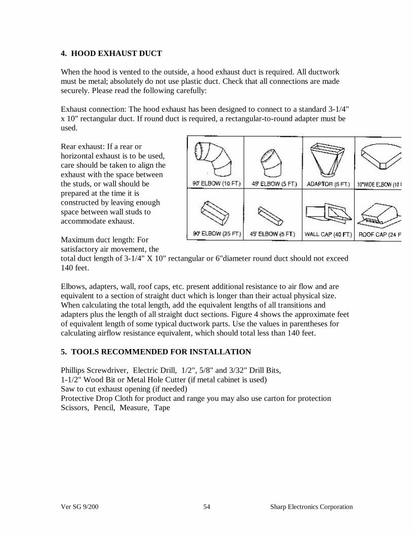
Ver SG 9/200 54 Sharp Electronics Corporation
4. HOOD EXHAUST DUCT
When the hood is vented to the outside, a hood exhaust duct is required. All ductworkmust be metal; absolutely do not use plastic duct. Check that all connections are madesecurely. Please read the following carefully:
Exhaust connection: The hood exhaust has been designed to connect to a standard 3-1/4"x 10" rectangular duct. If round duct is required, a rectangular-to-round adapter must beused.
Rear exhaust: If a rear orhorizontal exhaust is to be used,care should be taken to align theexhaust with the space betweenthe studs, or wall should beprepared at the time it isconstructed by leaving enoughspace between wall studs toaccommodate exhaust.
Maximum duct length: Forsatisfactory air movement, thetotal duct length of 3-1/4" X 10" rectangular or 6"diameter round duct should not exceed140 feet.
Elbows, adapters, wall, roof caps, etc. present additional resistance to air flow and areequivalent to a section of straight duct which is longer than their actual physical size.When calculating the total length, add the equivalent lengths of all transitions andadapters plus the length of all straight duct sections. Figure 4 shows the approximate feetof equivalent length of some typical ductwork parts. Use the values in parentheses forcalculating airflow resistance equivalent, which should total less than 140 feet.
5. TOOLS RECOMMENDED FOR INSTALLATION
Phillips Screwdriver, Electric Drill, 1/2", 5/8" and 3/32" Drill Bits,1-1/2" Wood Bit or Metal Hole Cutter (if metal cabinet is used)Saw to cut exhaust opening (if needed)Protective Drop Cloth for product and range you may also use carton for protectionScissors, Pencil, Measure, Tape
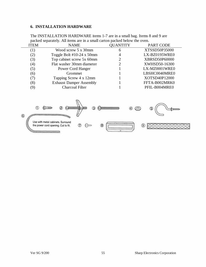
Ver SG 9/200 55 Sharp Electronics Corporation
6. INSTALLATION HARDWARE
The INSTALLATION HARDWARE items 1-7 are in a small bag. Items 8 and 9 arepacked separately. All items are in a small carton packed below the oven.
ITEM NAME QUANTITY PART CODE(1) Wood screw 5 x 30mm 6 XTSSD50P35000(2) Toggle Bolt #10-24 x 50mm 4 LX-BZ0195WRE0(3) Top cabinet screw 5x 60mm 2 XBRSD50P60000(4) Flat washer 30mm diameter 2 XWHSD50-16300(5) Power Cord Hanger 1 LX-MZ0001WRE0(6) Grommet 1 LBSHC0040MRE0(7) Tapping Screw 4 x 12mm 1 XOTSD40P12000(8) Exhaust Damper Assembly 1 FFTA-B002MRK0(9) Charcoal Filter 1 PFIL-B004MRE0

Ver SG 9/200 56 Sharp Electronics Corporation
TIP
The dotted cutting line on the packing carton can be cut in order to assist positioning theoven before placing oven on the Mounting Plate See Figure below right
7. PREPARATION OF THE OVEN
1. Open the bottom of the carton, remove oven,all packing materials, Installation Instructions,Wall Template, Top Template and CharcoalFilter; however, DO NOT REMOVE THEWAVEGUIDE COVER, which is located on theceiling in the oven cavity.
2. CHECK THE OVEN.Check the oven for any damage, such as misalignedor bent door, damaged door seals and sealingsurfaces, broken or loose door hinges and latches and dents inside the cavity or on thedoor. If there is any damage, do not operate the oven and contact your dealer or SHARPAUTHORIZED SERVICER.
3. Remove and save Screw (A) as shown in Figure 6.
4. Push down carefully on the tabs (B) and (C) at the ends of the Louver to disengage it.Pull the Louver away from the unit and set aside.
5. Loosen the two Mounting Screws (D) which secure the Mounting Plate to the rear sideof the oven. Remove the Mounting Plate. See Figure 7
Figure 6 Figure 7
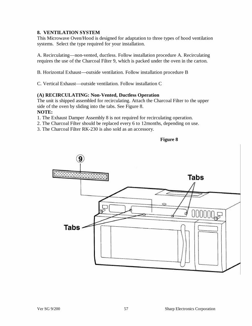
Ver SG 9/200 57 Sharp Electronics Corporation
8. VENTILATION SYSTEMThis Microwave Oven/Hood is designed for adaptation to three types of hood ventilationsystems. Select the type required for your installation.
A. Recirculating— non-vented, ductless. Follow installation procedure A. Recirculatingrequires the use of the Charcoal Filter 9, which is packed under the oven in the carton.
B. Horizontal Exhaust— outside ventilation. Follow installation procedure B
C. Vertical Exhaust— outside ventilation. Follow installation C
(A) RECIRCULATING: Non-Vented, Ductless OperationThe unit is shipped assembled for recirculating. Attach the Charcoal Filter to the upperside of the oven by sliding into the tabs. See Figure 8.NOTE:1. The Exhaust Damper Assembly 8 is not required for recirculating operation.2. The Charcoal Filter should be replaced every 6 to 12months, depending on use.3. The Charcoal Filter RK-230 is also sold as an accessory.
Figure 8

Ver SG 9/200 58 Sharp Electronics Corporation
(B) HORIZONTAL EXHAUST: Outside Ventilation1. Remove and save 2 screws from back edge and 1 screw from the top center of FanCover Bracket. Remove Fan Cover Bracket by sliding it in the opposite direction of thearrow on the Fan Cover Bracket, as shown in Figure 9.2. Withdraw Hood Fan Unit carefully and slip wires out of Wire Box. See Figure 10.CAUTION: Do not pull or stretch hood fan wiring.3. Rotate the Hood Fan Unit and turn end-over-end so that the fan blade openings arefacing the back of the oven. Replace Hood Fan Unit into the oven. Be careful not to pinchthe lead wire between the inner bracket and the Hood Fan Unit. See Figure 11.4. Put the lead wire into Wire Box. See Figure 12.5. Replace the Fan Cover Bracket by sliding it into the slits in the same direction as thearrow on the Fan Cover Bracket. Make sure the fan blades are visible through the rearopenings in the oven before proceeding. Attach Fan Cover Bracket to unit with 3 screws,which were removed in Step 1 above. See Figure 12. The Hood Fan Unit is now rotatedfor horizontal exhaust operation.6. Attach the Exhaust Damper Assembly 8 to the back of the Mounting Plate by sliding itinto the slits in the same direction as the arrow. See Figure 13. Using Tapping Screw 4 X12 7 from the INSTALLATION HARDWARE, tighten into place.

Ver SG 9/200 59 Sharp Electronics Corporation
(C) VERTICAL EXHAUST: Outside Ventilation
1.Remove and save 2 screws from back edge and 1 screw from the top center of the FanCover Bracket. Remove Fan Cover Bracket by sliding it in the opposite direction of thearrow on the Fan Cover Bracket as shown in Figure 9.
2. Withdraw Hood Fan Unit carefully and slip wires out of Wire Box. CAUTION: Do notpull or stretch hood fan wiring. See Figure 10.
3. Turn the Hood Fan Unitend-over-end. Rotate the Hood FanUnit 90 degrees so that the fan bladeopenings are facing upward.Replace Hood Fan Unit into theoven. Becareful not to pinch the lead wirebetween the inner bracket and theHood Fan Unit. See Figure 14.
4. Put the lead wire into Wire Box.See Figure 14.
5. Replace the Fan Cover Bracketby sliding it into the slits in the samedirection as the arrow on the Fan Cover Bracket. Make sure the fan blades are visiblethrough the top openings in the oven before proceeding. Attach the Fan Cover Bracket tounit with 3 screws, which were removed in Step 1 above. See Figure 12. The Hood FanUnit is now rotated for vertical exhaust operation.
6. Attach the Exhaust Damper Assembly to the fan cover on the top of the outercasecabinet after mounting the oven. To attach the Exhaust Damper Assembly, refer toMOUNTING OVEN TO THE WALL, Step 7.
Figure 14

Ver SG 9/200 60 Sharp Electronics Corporation
9. OVEN INSTALLATIONTHIS OVEN CANNOT BE PROPERLY INSTALLED WITHOUT REFERRING TOTHE MOUNTING INSTRUCTIONS FOUND ON BOTH TEMPLATES.
THE NEXT STEP IS TO READ AND FOLLOW MOUNTING INFORMATION ONBOTH TOP CABINET AND WALL TEMPLATES.
NOTE: THIS OVEN SHOULD BE ATTACHED TO AT LEAST ONE WALL STUD.See WALL CONSTRUCTION step 2.
MOUNTING PLATE
1. Separate 4 Toggle Bolts, 2, packed in the INSTALLATION HARDWARE, from theToggle Nuts.2. Use Wood Screws, 1 to attach Mounting Plate to the stud or studs. Use Toggle Bolts toattach Mounting Plate through the holes at A, B, C and D; UNLESS THOSE HOLESARE LOCATED ON THE STUD. Insert one Toggle Bolt into A, B. C and D whereappropriate (these correspond to the holes of the Wall Template) and put the Toggle Nutsonto the Toggle Bolts. Figure 15.Refer to instructions in Wall Template.
3. Position the Mounting Plate with the Toggle Bolts attached at the wall location andinsert Toggle Nuts and Bolts through the holes in the wall with the Toggle Nuts closed.Figure 16. Use Wood Screws 3 to attach the Mounting Plate to studs.
NOTE: Before insertion, be sure you leave a space more than the thickness of the wallbetween the Mounting Plate and the end of each of the Toggle Nuts (in the closedposition). If you do not leave enough space, the Toggle Nut will not be able to open onthe other side of the wall. Also, once a Toggle Nut opens, it cannot be withdrawn fromthe hole; therefore make sure all of the Toggles are in the correct position beforeinsertion.
4. Align the Mounting Plate carefully and hold in position while tightening Toggle Bolts.Pull Toggle Bolt toward you and turn clockwise to tighten. Figure 17.
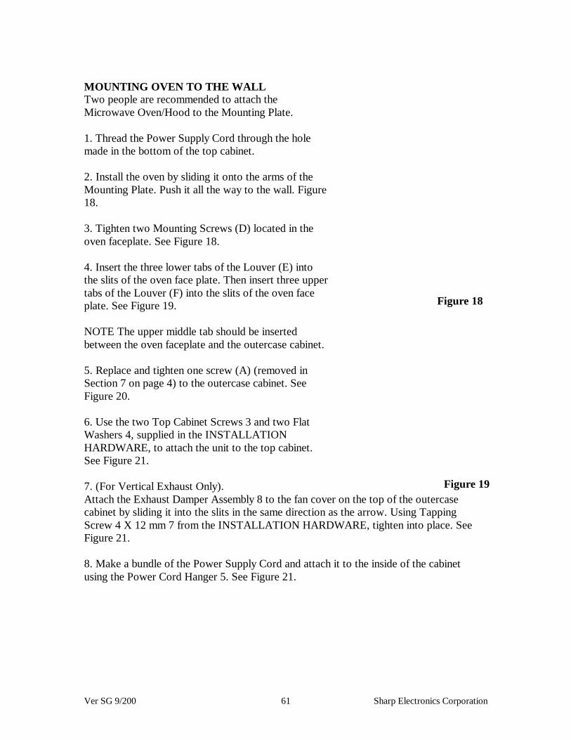
Ver SG 9/200 61 Sharp Electronics Corporation
MOUNTING OVEN TO THE WALLTwo people are recommended to attach theMicrowave Oven/Hood to the Mounting Plate.
1. Thread the Power Supply Cord through the holemade in the bottom of the top cabinet.
2. Install the oven by sliding it onto the arms of theMounting Plate. Push it all the way to the wall. Figure18.
3. Tighten two Mounting Screws (D) located in theoven faceplate. See Figure 18.
4. Insert the three lower tabs of the Louver (E) intothe slits of the oven face plate. Then insert three uppertabs of the Louver (F) into the slits of the oven faceplate. See Figure 19.
NOTE The upper middle tab should be insertedbetween the oven faceplate and the outercase cabinet.
5. Replace and tighten one screw (A) (removed inSection 7 on page 4) to the outercase cabinet. SeeFigure 20.
6. Use the two Top Cabinet Screws 3 and two FlatWashers 4, supplied in the INSTALLATIONHARDWARE, to attach the unit to the top cabinet.See Figure 21.
7. (For Vertical Exhaust Only).Attach the Exhaust Damper Assembly 8 to the fan cover on the top of the outercasecabinet by sliding it into the slits in the same direction as the arrow. Using TappingScrew 4 X 12 mm 7 from the INSTALLATION HARDWARE, tighten into place. SeeFigure 21.
8. Make a bundle of the Power Supply Cord and attach it to the inside of the cabinetusing the Power Cord Hanger 5. See Figure 21.
Figure 18
Figure 19

Ver SG 9/200 62 Sharp Electronics Corporation
Figure 21 Figure 20

Ver SG 9/200 63 Sharp Electronics Corporation
CHECK LIST FOR INSTALLATION1. Make sure the unit has been installed according to all of the Installation Instructions,the Top Template and Wall Template.
2. Remove all packing material from the oven.
3. Plug in the power cord.
4. Read the Operation Manual.
5. Keep the Installation Instructions for the local electrical inspector's use.
ACCESSORIES Check with your dealer or order directly from the SHARP Accessoriesand Supplies Center. Call toll-free1 -800-642-2122.
1. CHARCOAL FILTER (RK-230). Filter is used when hood exhaust is recirculatedonly.
2. FILLER PANEL KIT. This is available for use when the oven is installed in a 36" or42" wide opening. The metal filler panels come in pairs, each either 3 or 6 inches wide.For information and to purchase contact:
MODERN-AIRE MANUFACTURING CORPORATION7319 Lankershim Blvd.North Hollywood, CA 91605Phone: (818) 765-9870 or (213) 875-1350Fax: (818) 765-4916SHARP
SHARP ELECTRONICS CORPORATION TINSEB177MRROSharp Plaza, Mahwah, New Jersey 07430-2135 Printed in U.S.A.

Ver SG 9/200 64 Sharp Electronics Corporation
GENERAL SERVICE HINTS
Problem SolutionA thumping sound is heard when power is
applied to the power transformerCheck the transformer mounting at the baseof the unit. Bend the transformer tabs up toeliminate any play between the transformer
and the base.Cannot clear the display Check the door sensing or stop switch
circuit for an open. If the circuits are OK,follow the key matrix to determine if theproblem is in the key unit or control unit
Turntable rotates in either direction. This is normalControl unit is dead Check foil fuse. Jumper in a spare fuse
before replacing the control unit. Allcontrol units contain foil fuses, which are
built into the foil pattern on the circuitboard. The foil fuses are located on theprimary side of the transformer. Extra
fuses are provided so that the unit may berepaired without having to be replaced.Check the varistor, replace if necessary
AH sensor works erratically Ensure the wiring on the power transformeris correct. Red wire closet to outer cabinet
wall.Wave guide cover burns Check oven for cleanliness. Advise
customerMonitor fuse opens every few months Check the fuse holder to ensure the clamps
have not experienced metal fatigue.

MODEL REF PART CODE DESCRIPTION
Ver SG 9/200 65 Sharp Electronics Corporation
Commonly used parts for 2000 modelsModel Ref Part DescR-120DB 1-1 QSW-MA137WRE0 Secondary interlock switch & door
sensing switch1-2 FFS-BA027WRKZ C/T fuse & monitor switch assembly1-5 FH-DZA095WRKZ High voltage rectifier1-6 RC-QZA209WRE0 High voltage capacitor1-7 RMOTEA383WRE0 Fan motor1-8 RV-MZA195WRE0 Magnetron1-9 RLMPTA068WRE0 Oven lamp1-10 RMOTDA211WRE0 Turntable motor1-11 RTHM-A117WRE0 Thermal cutout1-12 RTRN-A606WRZZ Power transformer2-1 GCABUA754WRPZ Outer case cabinet3-1 DPWBFC045WRUZ Control unit3-2 FPNLCB485WRKZ Panel frame with key unit3-2-1 HPNLCB607WRFZ Control panel3-2-2 PSHEPA723WREZ Key sheet4-1 PHOK-A117WRPZ Latch hook4-12 PCOVPA359WREZ Waveguide cover5-1 FDORFA341WRTZ Door panel5-2 GWAKPA705WRRZ Door frame5-3 JBTN-B119WRFZ Start / Minute Plus button & Stop / Clear
button5-5 LSTPPA194WRFZ Latch head5-8 GCOVHA418WRFZ Choke cover6-1 FROLPA089WRK0 Turntable support6-2 NTNT-A060WRE0 Turntable6-3 TINSEA831WRRZ Instruction book
R-120DG 1-1 QSW-MA137WRE0 Secondary interlock switch & doorsensing switch
1-2 FFS-BA027WRKZ C/T fuse & monitor switch assembly1-5 FH-DZA095WRKZ High voltage rectifier1-6 RC-QZA209WRE0 High voltage capacitor1-7 RMOTEA383WRE0 Fan motor1-8 RV-MZA195WRE0 Magnetron1-8 RV-MZA198WRE0 Magnetron (Interchangeable)1-9 RLMPTA068WRE0 Oven lamp1-10 RMOTDA211WRE0 Turntable motor1-10 RMOTDA186WRE0 Turntable motor (Interchangeable)1-11 RTHM-A117WRE0 Thermal cutout1-12 RTRN-A606WRZZ Power transformer2-1 GCABUA781WRPZ Outer case cabinet

MODEL REF PART CODE DESCRIPTION
Ver SG 9/200 66 Sharp Electronics Corporation
3-1 DPWBFC045WRUZ Control unit3-2 FPNLCB485WRKZ Panel frame with key unit3-2-1 HPNLCB607WRFZ Control panel3-2-2 PSHEPA723WREZ Key sheet4-1 PHOK-A117WRPZ Latch hook4-12 PCOVPA359WREZ Waveguide cover5-1 FDORFA341WRTZ Door panel5-2 GWAKPA747WRRZ Door frame5-3 JBTN-B119WRFZ Start / Minute Plus button & Stop / Clear
button5-5 LSTPPA194WRFZ Latch head5-8 GCOVHA418WRFZ Choke cover6-1 FROLPA089WRK0 Turntable support6-2 NTNT-A060WRE0 Turntable6-3 TINSEA857WRRZ Instruction book
R-120DK 1-1 QSW-MA137WRE0 Secondary interlock switch & doorsensing switch
1-2 FFS-BA027WRKZ C/T fuse & monitor switch assembly1-5 FH-DZA095WRKZ High voltage rectifier1-6 RC-QZA209WRE0 High voltage capacitor1-7 RMOTEA383WRE0 Fan motor1-8 RV-MZA195WRE0 Magnetron1-9 RLMPTA068WRE0 Oven lamp1-10 RMOTDA211WRE0 Turntable motor1-11 RTHM-A117WRE0 Thermal cutout1-12 RTRN-A606WRZZ Power transformer2-1 GCABUA763WRPZ Outer case cabinet3-1 DPWBFC045WRUZ Control unit3-2 FPNLCB485WRKZ Panel frame with key unit3-2-1 HPNLCB607WRFZ Control panel3-2-2 PSHEPA723WREZ Key sheet4-1 PHOK-A117WRPZ Latch hook4-12 PCOVPA359WREZ Waveguide cover5-1 FDORFA341WRTZ Door panel5-2 GWAKPA719WRRZ Door frame5-3 JBTN-B119WRFZ Start / Minute Plus button & Stop / Clear
button5-5 LSTPPA194WRFZ Latch head5-8 GCOVHA418WRFZ Choke cover6-1 FROLPA089WRK0 Turntable support6-2 NTNT-A060WRE0 Turntable6-3 TINSEA831WRRZ Instruction book
R-120DP 1-1 QSW-MA137WRE0 Secondary interlock switch & door

MODEL REF PART CODE DESCRIPTION
Ver SG 9/200 67 Sharp Electronics Corporation
sensing switch1-2 FFS-BA027WRKZ C/T fuse & monitor switch assembly1-5 FH-DZA095WRKZ High voltage rectifier1-6 RC-QZA209WRE0 High voltage capacitor1-7 RMOTEA383WRE0 Fan motor1-8 RV-MZA195WRE0 Magnetron1-8 RV-MZA198WRE0 Magnetron (Interchangeable)1-9 RLMPTA068WRE0 Oven lamp1-10 RMOTDA211WRE0 Turntable motor1-10 RMOTDA186WRE0 Turntable motor (Interchangeable)1-11 RTHM-A117WRE0 Thermal cutout1-12 RTRN-A606WRZZ Power transformer2-1 GCABUA783WRPZ Outer case cabinet3-1 DPWBFC045WRUZ Control unit3-2 FPNLCB485WRKZ Panel frame with key unit3-2-1 HPNLCB607WRFZ Control panel3-2-2 PSHEPA723WREZ Key sheet4-1 PHOK-A117WRPZ Latch hook4-12 PCOVPA359WREZ Waveguide cover5-1 FDORFA341WRTZ Door panel5-2 GWAKPA749WRRZ Door frame5-3 JBTN-B119WRFZ Start / Minute Plus button & Stop / Clear
button5-5 LSTPPA194WRFZ Latch head5-8 GCOVHA418WRFZ Choke cover6-1 FROLPA089WRK0 Turntable support6-2 NTNT-A060WRE0 Turntable6-3 TINSEA857WRRZ Instruction book
R-120DR 1-1 QSW-MA137WRE0 Secondary interlock switch & doorsensing switch
1-2 FFS-BA027WRKZ C/T fuse & monitor switch assembly1-5 FH-DZA095WRKZ High voltage rectifier1-6 RC-QZA209WRE0 High voltage capacitor1-7 RMOTEA383WRE0 Fan motor1-8 RV-MZA195WRE0 Magnetron1-8 RV-MZA198WRE0 Magnetron (Interchangeable)1-9 RLMPTA068WRE0 Oven lamp1-10 RMOTDA211WRE0 Turntable motor1-10 RMOTDA186WRE0 Turntable motor (Interchangeable)1-11 RTHM-A117WRE0 Thermal cutout1-12 RTRN-A606WRZZ Power transformer2-1 GCABUA765WRPZ Outer case cabinet3-1 DPWBFC045WRUZ Control unit3-2 FPNLCB485WRKZ Panel frame with key unit3-2-1 HPNLCB607WRFZ Control panel

MODEL REF PART CODE DESCRIPTION
Ver SG 9/200 68 Sharp Electronics Corporation
3-2-2 PSHEPA723WREZ Key sheet4-1 PHOK-A117WRPZ Latch hook4-12 PCOVPA359WREZ Waveguide cover5-1 FDORFA341WRTZ Door panel5-2 GWAKPA721WRRZ Door frame5-3 JBTN-B119WRFZ Start / Minute Plus button & Stop / Clear
button5-5 LSTPPA194WRFZ Latch head5-8 GCOVHA418WRFZ Choke cover6-1 FROLPA089WRK0 Turntable support6-2 NTNT-A060WRE0 Turntable6-3 TINSEA831WRRZ Instruction book
R-120DS 1-1 QSW-MA137WRE0 Secondary interlock switch & doorsensing switch
1-2 FFS-BA027WRKZ C/T fuse & monitor switch assembly1-5 FH-DZA095WRKZ High voltage rectifier1-6 RC-QZA209WRE0 High voltage capacitor1-7 RMOTEA383WRE0 Fan motor1-8 RV-MZA195WRE0 Magnetron1-8 RV-MZA198WRE0 Magnetron (Interchangeable)1-9 RLMPTA068WRE0 Oven lamp1-10 RMOTDA211WRE0 Turntable motor1-10 RMOTDA186WRE0 Turntable motor (Interchangeable)1-11 RTHM-A117WRE0 Thermal cutout1-12 RTRN-A606WRZZ Power transformer2-1 GCABUA779WRPZ Outer case cabinet3-1 DPWBFC045WRUZ Control unit3-2 FPNLCB485WRKZ Panel frame with key unit3-2-1 HPNLCB607WRFZ Control panel3-2-2 PSHEPA723WREZ Key sheet4-1 PHOK-A117WRPZ Latch hook4-12 PCOVPA359WREZ Waveguide cover5-1 FDORFA341WRTZ Door panel5-2 GWAKPA743WRRZ Door frame5-3 JBTN-B119WRFZ Start / Minute Plus button & Stop / Clear
button5-5 LSTPPA194WRFZ Latch head5-8 GCOVHA418WRFZ Choke cover6-1 FROLPA089WRK0 Turntable support6-2 NTNT-A060WRE0 Turntable6-3 TINSEA857WRRZ Instruction book
R-120DW 1-1 QSW-MA137WRE0 Secondary interlock switch & doorsensing switch
1-2 FFS-BA027WRKZ C/T fuse & monitor switch assembly

MODEL REF PART CODE DESCRIPTION
Ver SG 9/200 69 Sharp Electronics Corporation
1-5 FH-DZA095WRKZ High voltage rectifier1-6 RC-QZA209WRE0 High voltage capacitor1-7 RMOTEA383WRE0 Fan motor1-8 RV-MZA195WRE0 Magnetron1-8 RV-MZA198WRE0 Magnetron (Interchangeable)1-9 RLMPTA068WRE0 Oven lamp1-10 RMOTDA211WRE0 Turntable motor1-10 RMOTDA186WRE0 Turntable motor (Interchangeable)1-11 RTHM-A117WRE0 Thermal cutout1-12 RTRN-A606WRZZ Power transformer2-1 GCABUA761WRPZ Outer case cabinet3-1 DPWBFC045WRUZ Control unit3-2 FPNLCB485WRKZ Panel frame with key unit3-2-1 HPNLCB607WRFZ Control panel3-2-2 PSHEPA723WREZ Key sheet4-1 PHOK-A117WRPZ Latch hook4-12 PCOVPA359WREZ Waveguide cover5-1 FDORFA341WRTZ Door panel5-2 GWAKPA717WRRZ Door frame5-3 JBTN-B119WRFZ Start / Minute Plus button & Stop / Clear
button5-5 LSTPPA194WRFZ Latch head5-8 GCOVHA418WRFZ Choke cover6-1 FROLPA089WRK0 Turntable support6-2 NTNT-A060WRE0 Turntable6-3 TINSEA831WRRZ Instruction book
R-204CW 1-1 QSW-MA131WRE0 Secondary interlock switch & doorsensing switch
1-2 FFS-BA020WRK0 C/T fuse assembly1-5 FH-DZA081WRK0 High voltage rectifier assembly1-6 RC-QZA228WRE0 High voltage capacitor1-6 RC-QZA201WRE0 High voltage capacitor (interchangeable)1-7 RMOTEA355WRE0 Fan motor1-7 RMOTEA338WRE0 Fan motor (interchangeable)1-8 RV-MZA226WRE0 Magnetron1-8 RV-MZA282WRE0 Magnetron (interchangeable)1-9 RLMPTA030WRE0 Oven lamp1-10 RMOTDA211WRE0 Turntable motor1-10 RMOTDA186WRE0 Turntable motor (interchangeable)1-11 RTHM-A078WRE0 Thermal cut-out1-12 RTRN-A561WRE0 Power transformer

MODEL REF PART CODE DESCRIPTION
Ver SG 9/200 70 Sharp Electronics Corporation
2-1 GCABUA696WRP0 Outer case cabinet3-1 DPWBFB973WRU0 Control unit3-2 FPNLCB426WRK0 Control panel frame with key unit and
LCD3-2-1 FUNTKA928WRE0 Key unit3-2-2 RLCDSA045DRE0 Liquid crystal display4-1 PHOK-A105WRF0 Latch hook4-11 PCOVPA276WRE0 Waveguide cover5-1 FDORFA321WRT0 Door panel5-2 GWAKPA628WRF0 Door frame5-3 HPNL-A738WRRZ Door screen5-4 LSTPPA175WRF0 Latch Head5-7 GCOVHA390WRF0 Choke cover6-1 FROLPA090WRK0 Turntable support6-2 NTNT-A094WRE0 Turntable6-3 TINSEA852WRRZ Instruction book
R-220DW 1-1 QSW-MA137WRE0 Secondary interlock switch & doorsensing switch
1-2 FFS-BA025WRKZ C/T fuse & monitor switch assembly1-5 FH-DZA081WRK0 High voltage rectifier1-6 RC-QZA228WRE0 High voltage capacitor1-6 RC-QZA200WRE0 High voltage capacitor (interchangeable)1-7 RMOTEA355WRE0 Fan motor1-7 RMOTEA383WRE0 Fan motor (interchangeable)1-8 RV-MZA226WRE0 Magnetron1-9 RLMPTA030WRE0 Oven lamp1-9 RLMPTA068WRE0 Oven lamp (interchangeable)1-10 RMOTDA211WRE0 Turntable motor1-10 RMOTDA186WRE0 Turntable motor (interchangeable)1-11 RTHM-A078WRE0 Thermal cut-out1-12 RTRN-A604WRZZ Power transformer2-1 GCABUA696WRP0 Outer cabinet3-1 DPWBFC027WRUZ Control unit3-2 FPNLCB477WRKZ Control panel frame with key unit & LCD3-2-1 FUNTKA972WREZ Key unit3-2-2 RLCDSA045DRE0 Liquid crystal display3-3 QCNC-A012WRE0 Rubber connector4-1 PHOK-A105WRF0 Latch hook4-11 PCOVPA276WRE0 Waveguide cover5-1 FDORFA321WRT0 Door panel5-2 GWAKPA628WRF0 Door frame panel5-3 HPNL-A738WRRZ Door screen5-4 LSTPPA175WRF0 Latch head5-5 MSPRTA084WRE0 Latch spring

MODEL REF PART CODE DESCRIPTION
Ver SG 9/200 71 Sharp Electronics Corporation
5-7 GCOVHA390WRF0 Choke cover6-1 FROLPA089WRK0 Turntable support6-2 NTNT-A094WRE0 Turntable6-3 TINSEA828WRRZ Instruction book
R-230DK 1-1 QSW-MA137WRE0 Secondary interlock switch & doorsensing switch
1-2 FFS-BA025WRKZ C/T fuse & monitor switch assembly1-5 FH-DZA081WRK0 High voltage rectifier1-6 RC-QZA228WRE0 High voltage capacitor1-6 RC-QZA200WRE0 High voltage capacitor (interchangeable)1-7 RMOTEA355WRE0 Fan motor1-7 RMOTEA383WRE0 Fan motor (interchangeable)1-8 RV-MZA226WRE0 Magnetron1-9 RLMPTA030WRE0 Oven lamp1-9 RLMPTA068WRE0 Oven lamp (interchangeable)1-10 RMOTDA211WRE0 Turntable motor1-10 RMOTDA186WRE0 Turntable motor (interchangeable)1-11 RTHM-A078WRE0 Thermal cut-out1-12 RTRN-A604WRZZ Power transformer2-1 GCABUA756WRPZ Outer cabinet3-1 DPWBFC028WRUZ Control unit3-2 FPNLCB482WRKZ Control panel frame with key unit & LCD3-2-1 FUNTKA977WREZ Key unit3-2-2 RLCDSA045DRE0 Liquid crystal display3-3 QCNC-A012WRE0 Rubber connector4-1 PHOK-A105WRF0 Latch hook4-11 PCOVPA276WRE0 Waveguide cover5-1 FDORFA321WRT0 Door panel5-2 GWAKPA709WRFZ Door frame5-3 HPNL-A738WRRZ Door screen5-4 LSTPPA175WRF0 Latch head5-5 MSPRTA084WRE0 Latch spring5-7 GCOVHA390WRF0 Choke cover6-1 FROLPA089WRK0 Turntable support6-2 NTNT-A094WRE0 Turntable6-3 TINSEA828WRRZ Instruction book
R-230DW 1-1 QSW-MA137WRE0 Secondary interlock switch & doorsensing switch
1-2 FFS-BA025WRKZ C/T fuse & monitor switch assembly1-5 FH-DZA081WRK0 High voltage rectifier1-6 RC-QZA228WRE0 High voltage capacitor1-6 RC-QZA200WRE0 High voltage capacitor (interchangeable)1-7 RMOTEA355WRE0 Fan motor

MODEL REF PART CODE DESCRIPTION
Ver SG 9/200 72 Sharp Electronics Corporation
1-7 RMOTEA383WRE0 Fan motor (interchangeable)1-8 RV-MZA226WRE0 Magnetron1-9 RLMPTA030WRE0 Oven lamp1-9 RLMPTA068WRE0 Oven lamp (interchangeable)1-10 RMOTDA211WRE0 Turntable motor1-10 RMOTDA186WRE0 Turntable motor (interchangeable)1-11 RTHM-A078WRE0 Thermal cut-out1-12 RTRN-A604WRZZ Power transformer2-1 GCABUA696WRP0 Outer cabinet3-1 DPWBFC028WRUZ Control unit3-2 FPNLCB481WRKZ Control panel frame with key unit & LCD3-2-1 FUNTKA976WREZ Key unit3-2-2 RLCDSA045DRE0 Liquid crystal display3-3 QCNC-A012WRE0 Rubber connector4-1 PHOK-A105WRF0 Latch hook4-11 PCOVPA276WRE0 Waveguide cover5-1 FDORFA321WRT0 Door panel5-2 GWAKPA628WRFZ Door frame5-3 HPNL-A738WRRZ Door screen5-4 LSTPPA175WRF0 Latch head5-5 MSPRTA084WRE0 Latch spring5-7 GCOVHA390WRF0 Choke cover6-1 FROLPA089WRK0 Turntable support6-2 NTNT-A094WRE0 Turntable6-3 TINSEA828WRRZ Instruction book
R-305DW 1-1 QSW-MA147WRZZ 2nd interlock switch / door sensing switch1-2 QFSHDA009WRE0 Fuse holder1-3 FFS-BA021WRK0 Monitor fuse 20A & monitor switch1-4 RTHM-A078WRE0 Thermal cut-out1-6 FH-DZA088WRK0 High voltage rectifier assembly1-7 RC-QZA173WRE0 High voltage capacitor1-8 RV-MZA288WRE0 Magnetron1-11 RLMPTA068WRE0 Oven lamp1-11 RLMPTA030WRE0 Oven lamp (interchangeable)1-12 RMOTDA229WRE0 Turntable motor1-12 RMOTDA211WRE0 Turntable motor (interchangeable)1-13 RTHM-A080WRE0 Thermal cut-out1-14 RTRN-A576WRE0 Power transformer2-1 GCABUA690WRP0 Outer case cabinet3-1 DPWBFC021WRKZ Power unit4-3 PHOK-A116WRFZ Latch hook4-14 PCOVPA349WRE0 Waveguide cover5-1 FDORFA332WRT0 Door panel5-3 GWAKPA701WRRZ Door frame5-4 HPNL-A734WRRZ Door screen

MODEL REF PART CODE DESCRIPTION
Ver SG 9/200 73 Sharp Electronics Corporation
5-5 LSTPPA193WRFZ Latch head5-9 MSPRTA187WRE0 Latch spring5-9 GCOVHA417WRFZ Choke cover6-1 FROLPA079WRK0 Turntable support6-2 NTNT-A079WRE0 Turntable tray6-8 TINSEA848WRRZ Instruction book
R-308DW 1-1 QSW-MA147WRZZ 2nd interlock switch / door sensing switch1-3 FFS-BA021WRK0 Monitor fuse 20A & monitor switch1-4 RTHM-A078WRE0 Thermal cut-out1-6 FH-DZA094WRKZ High voltage rectifier assembly1-7 RC-QZA268WRZZ High voltage capacitor1-8 RV-MZA288WRE0 Magnetron1-11 RLMPTA068WRE0 Oven lamp1-12 RMOTDA229WRE0 Turntable motor1-12 RMOTDA211WRE0 Turntable motor (interchangeable)1-13 RTHM-A080WRE0 Thermal cut-out1-14 RTRN-A603WRZZ Power transformer2-1 GCABUA690WRP0 Outer case cabinet3-1 DPWBFC021WRKZ Power unit3-2 DPWBFC020WRKZ CPU unit3-3 FPNLCB499WRKZ Control panel frame with key unit3-3-1 FUNTKA991WREZ Key unit4-3 PHOK-A116WRFZ Latch hook4-14 PCOVPA349WRE0 Waveguide cover5-1 FDORFA332WRT0 Door panel5-3 GWAKPA701WRRZ Door frame5-4 HPNL-A734WRRZ Door screen5-5 LSTPPA193WRFZ Latch head5-6 MSPRTA187WRE0 Latch spring5-9 GCOVHA417WRFZ Choke cover6-1 FROLPA079WRRK0 Turntable support6-2 NTNT-A084WRE0 Turntable tray6-8 TINSEA826WRRZ Instruction book
R-310DK 1-1 QSW-MA147WRZZ 2nd interlock switch / door sensing switch1-3 FFS-BA021WRK0 Monitor fuse 20A & monitor switch1-4 RTHM-A078WRE0 Thermal cut-out1-6 FH-DZA094WRKZ High voltage rectifier assembly1-7 RC-QZA268WRZZ High voltage capacitor1-8 RV-MZA288WRE0 Magnetron1-11 RLMPTA068WRE0 Oven lamp1-12 RMOTDA229WRE0 Turntable motor1-12 RMOTDA211WRE0 Turntable motor (interchangeable)1-13 RTHM-A080WRE0 Thermal cut-out1-14 RTRN-A603WRZZ Power transformer

MODEL REF PART CODE DESCRIPTION
Ver SG 9/200 74 Sharp Electronics Corporation
2-1 GCABUA744WRPZ Outer case cabinet3-1 DPWBFC021WRKZ Power unit3-2 DPWBFC020WRKZ CPU unit3-3 FPNLCB475WRKZ Control panel frame with key unit3-3-1 FUNTKA970WREZ Key unit4-3 PHOK-A116WRFZ Latch hook4-14 PCOVPA349WRE0 Waveguide cover5-1 FDORFA332WRT0 Door panel5-3 GWAKPA694WRRZ Door frame5-4 HPNL-A731WRRZ Door screen5-5 LSTPPA193WRFZ Latch head5-6 MSPRTA187WRE0 Latch spring5-9 GCOVHA417WRFZ Choke cover6-1 FROLPA079WRRK0 Turntable support6-2 NTNT-A079WRE0 Turntable tray6-8 TINSEA826WRRZ Instruction book
R-310DW 1-1 QSW-MA147WRZZ 2nd interlock switch / door sensing switch1-3 FFS-BA021WRK0 Monitor fuse 20A & monitor switch1-4 RTHM-A078WRE0 Thermal cut-out1-6 FH-DZA094WRKZ High voltage rectifier assembly1-7 RC-QZA268WRZZ High voltage capacitor1-8 RV-MZA288WRE0 Magnetron1-11 RLMPTA068WRE0 Oven lamp1-12 RMOTDA229WRE0 Turntable motor1-12 RMOTDA211WRE0 Turntable motor (interchangeable)1-13 RTHM-A080WRE0 Thermal cut-out1-14 RTRN-A603WRZZ Power transformer2-1 GCABUA744WRPZ Outer case cabinet3-1 DPWBFC021WRKZ Power unit3-2 DPWBFC020WRKZ CPU unit3-3 FPNLCB478WRKZ Control panel frame with key unit3-3-1 FUNTKA973WREZ Key unit4-3 PHOK-A116WRFZ Latch hook4-14 PCOVPA349WRE0 Waveguide cover5-1 FDORFA332WRT0 Door panel5-3 GWAKPA701WRRZ Door frame5-4 HPNL-A734WRRZ Door screen5-5 LSTPPA193WRFZ Latch head5-6 MSPRTA187WRE0 Latch spring5-9 GCOVHA417WRFZ Choke cover6-1 FROLPA079WRRK0 Turntable support6-2 NTNT-A079WRE0 Turntable tray6-8 TINSEA826WRRZ Instruction book
R-320DK 1-1 QSW-MA147WRZZ 2nd interlock switch / door sensing switch

MODEL REF PART CODE DESCRIPTION
Ver SG 9/200 75 Sharp Electronics Corporation
1-3 FFS-BA021WRK0 Monitor fuse 20A and monitor switch1-4 RTHM-A078WRE0 Thermal cut-out1-6 FH-DZA094WRKZ High voltage rectifier assembly1-7 RC-QZA234WRE0 High voltage capacitor1-8 RV-MZA288WRE0 Magnetron1-9 RMOTEA383WRE0 Fan motor1-11 RLMPTA068WRE0 Oven lamp1-11 RLMPTA030WRE0 Oven lamp (interchangeable)1-12 RMOTDA229WRE0 Turntable motor1-12 RMOTDA211WRE0 Turntable motor (interchangeable)1-13 RTHM-A080WRE0 Thermal cut-out 145 degrees1-14 RTRN-A603WRZZ Power transformer1-15 FDTCTA197WRK0 AH sensor assembly2-1 GCABUA744WRPZ Outer case cabinet3-1 DPWBFC024WRKZ Power unit3-2 DPWBFC023WRKZ CPU unit3-3 FPNLCB484WRKZ Control panel frame with key unit3-3-1 FUNTKA980WREZ Key unit3-4 PSHEPA588WRE0 LED sheet3-5 LHLD-A219WRFZ LCD holder4-3 PHOK-A116WRFZ Latch hook4-14 PCOVPA349WRE0 Waveguide cover5-1 FDORFA332WRT0 Door panel5-2 PSHEPA382WRE0 Sealer film5-3 GWAKPA694WRRZ Door frame5-4 HPNL-A731WRRZ Door screen5-5 LSTPPA193WRFZ Latch head5-6 MSPRTA187WRE0 Latch spring5-9 GCOVHA417WRFZ Choke cover6-1 FROLPA079WRK0 Turntable table support6-2 NTNT-A079WRE0 Turntable tray6-8 TINSEA832WRRZ Instruction book
R-320DW 1-1 QSW-MA147WRZZ 2nd interlock switch / door sensing switch1-3 FFS-BA021WRK0 Monitor fuse 20A and monitor switch1-4 RTHM-A078WRE0 Thermal cut-out1-6 FH-DZA094WRKZ High voltage rectifier assembly1-7 RC-QZA234WRE0 High voltage capacitor1-8 RV-MZA288WRE0 Magnetron1-9 RMOTEA383WRE0 Fan motor1-11 RLMPTA068WRE0 Oven lamp1-11 RLMPTA030WRE0 Oven lamp (interchangeable)1-12 RMOTDA229WRE0 Turntable motor1-12 RMOTDA211WRE0 Turntable motor (interchangeable)1-13 RTHM-A080WRE0 Thermal cut-out 145 degrees1-14 RTRN-A603WRZZ Power transformer
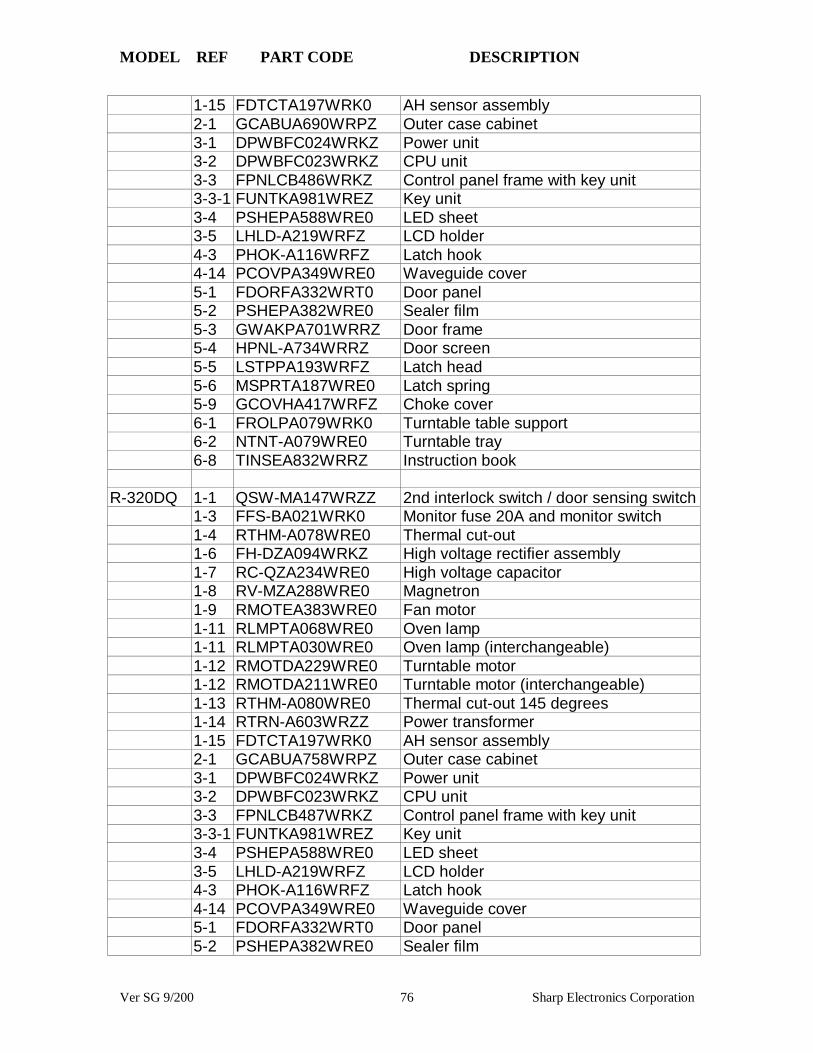
MODEL REF PART CODE DESCRIPTION
Ver SG 9/200 76 Sharp Electronics Corporation
1-15 FDTCTA197WRK0 AH sensor assembly2-1 GCABUA690WRPZ Outer case cabinet3-1 DPWBFC024WRKZ Power unit3-2 DPWBFC023WRKZ CPU unit3-3 FPNLCB486WRKZ Control panel frame with key unit3-3-1 FUNTKA981WREZ Key unit3-4 PSHEPA588WRE0 LED sheet3-5 LHLD-A219WRFZ LCD holder4-3 PHOK-A116WRFZ Latch hook4-14 PCOVPA349WRE0 Waveguide cover5-1 FDORFA332WRT0 Door panel5-2 PSHEPA382WRE0 Sealer film5-3 GWAKPA701WRRZ Door frame5-4 HPNL-A734WRRZ Door screen5-5 LSTPPA193WRFZ Latch head5-6 MSPRTA187WRE0 Latch spring5-9 GCOVHA417WRFZ Choke cover6-1 FROLPA079WRK0 Turntable table support6-2 NTNT-A079WRE0 Turntable tray6-8 TINSEA832WRRZ Instruction book
R-320DQ 1-1 QSW-MA147WRZZ 2nd interlock switch / door sensing switch1-3 FFS-BA021WRK0 Monitor fuse 20A and monitor switch1-4 RTHM-A078WRE0 Thermal cut-out1-6 FH-DZA094WRKZ High voltage rectifier assembly1-7 RC-QZA234WRE0 High voltage capacitor1-8 RV-MZA288WRE0 Magnetron1-9 RMOTEA383WRE0 Fan motor1-11 RLMPTA068WRE0 Oven lamp1-11 RLMPTA030WRE0 Oven lamp (interchangeable)1-12 RMOTDA229WRE0 Turntable motor1-12 RMOTDA211WRE0 Turntable motor (interchangeable)1-13 RTHM-A080WRE0 Thermal cut-out 145 degrees1-14 RTRN-A603WRZZ Power transformer1-15 FDTCTA197WRK0 AH sensor assembly2-1 GCABUA758WRPZ Outer case cabinet3-1 DPWBFC024WRKZ Power unit3-2 DPWBFC023WRKZ CPU unit3-3 FPNLCB487WRKZ Control panel frame with key unit3-3-1 FUNTKA981WREZ Key unit3-4 PSHEPA588WRE0 LED sheet3-5 LHLD-A219WRFZ LCD holder4-3 PHOK-A116WRFZ Latch hook4-14 PCOVPA349WRE0 Waveguide cover5-1 FDORFA332WRT0 Door panel5-2 PSHEPA382WRE0 Sealer film

MODEL REF PART CODE DESCRIPTION
Ver SG 9/200 77 Sharp Electronics Corporation
5-3 GWAKPA710WRRZ Door frame5-4 HPNL-A739WRRZ Door screen5-5 LSTPPA193WRFZ Latch head5-6 MSPRTA187WRE0 Latch spring5-9 GCOVHA417WRFZ Choke cover6-1 FROLPA079WRK0 Turntable table support6-2 NTNT-A079WRE0 Turntable tray6-8 TINSEA832WRRZ Instruction book
R-330DK 1-1 QSW-MA147WRZZ 2nd interlock switch / door sensing switch1-3 FFS-BA021WRK0 Monitor fuse 20A and monitor switch
assembly1-4 RTHM-A078WRE0 Thermal cut-out 125 degrees1-6 FH-DZA094WRKZ High voltage rectifier assembly1-8 RV-MZA288WRE0 Magnetron1-9 RMOTEA383WRE0 Fan motor1-9 RMOTEA355WRE0 Fan motor (interchangeable)1-11 RLMPTA068WRE0 Oven lamp1-11 RLMPTA030WRE0 Oven lamp (interchangeable)1-12 RMOTDA161WRE0 Turntable motor1-12 RMOTDA211WRE0 Turntable motor (interchangeable)1-13 RTHM-A080WRE0 Thermal cut-out 145 degrees1-14 RTRN-A603WRZZ Power transformer1-15 FDTCTA197WRK0 AH sensor assembly2-1 GCABUA744WRPZ Outer case cabinet3-1 DPWBFC044WRKZ Power unit3-2 DPWBFC025WRKZ CPU unit3-3 FPNLCB488WRKZ Control panel frame with key unit3-3-1 FUNTKA983WREZ Key unit3-4 PSHEPA672WRE0 LED sheet3-5 LHLD-A185WRF0 LCD holder4-3 PHOK-A116WRFZ Latch hook4-14 PCOVPA349WRE0 Waveguide cover5-1 FDORFA332WRT0 Door panel5-2 PSHEPA382WRE0 Sealer film5-3 GWAKPA713WRRZ Door frame5-4 HPNL-A740WRRZ Door screen5-5 LSTPPA193WRFZ Latch head5-6 MSPRTA187WRE0 Latch spring5-9 GCOVHA417WRFZ Choke cover6-1 FROLPA079WRK0 Turntable support6-2 NTNT-A079WRE0 Turntable tray6-8 TINSEA834WRRZ Instruction book
R-330DW 1-1 QSW-MA147WRZZ 2nd interlock switch / door sensing switch1-3 FFS-BA021WRK0 Monitor fuse 20A and monitor switch

MODEL REF PART CODE DESCRIPTION
Ver SG 9/200 78 Sharp Electronics Corporation
assembly1-4 RTHM-A078WRE0 Thermal cut-out 125 degrees1-6 FH-DZA094WRKZ High voltage rectifier assembly1-8 RV-MZA288WRE0 Magnetron1-9 RMOTEA383WRE0 Fan motor1-9 RMOTEA355WRE0 Fan motor (interchangeable)1-11 RLMPTA068WRE0 Oven lamp1-11 RLMPTA030WRE0 Oven lamp (interchangeable)1-12 RMOTDA161WRE0 Turntable motor1-12 RMOTDA211WRE0 Turntable motor (interchangeable)1-13 RTHM-A080WRE0 Thermal cut-out 145 degrees1-14 RTRN-A603WRZZ Power transformer1-15 FDTCTA197WRK0 AH sensor assembly2-1 GCABUA744WRPZ Outer case cabinet3-1 DPWBFC044WRKZ Power unit3-2 DPWBFC025WRKZ CPU unit3-3 FPNLCB489WRKZ Control panel frame with key unit3-3-1 FUNTKA984WREZ Key unit3-4 PSHEPA672WRE0 LED sheet3-5 LHLD-A185WRF0 LCD holder4-3 PHOK-A116WRFZ Latch hook4-14 PCOVPA349WRE0 Waveguide cover5-1 FDORFA332WRT0 Door panel5-2 PSHEPA382WRE0 Sealer film5-3 GWAKPA715WRRZ Door frame5-4 HPNL-A742WRRZ Door screen5-5 LSTPPA193WRFZ Latch head5-6 MSPRTA187WRE0 Latch spring5-9 GCOVHA417WRFZ Choke cover6-1 FROLPA079WRK0 Turntable support6-2 NTNT-A079WRE0 Turntable tray6-8 TINSEA834WRRZ Instruction book
R-340DK 1-1 QSW-MA147WRZZ 2nd interlock switch / door sensing switch1-3 FFS-BA021WRK0 Monitor fuse 20A and monitor switch
assembly1-4 RTHM-A078WRE0 Thermal cut-out125 degrees1-6 FH-DZA094WRKZ High voltage rectifier assembly1-7 RC-QZA234WRE0 High voltage capacitor1-8 RV-MZA288WRE0 Magnetron1-9 RMOTEA383WRE0 Fan motor1-9 RMOTEA355WRE0 Fan motor (interchangeable)1-11 RLMPTA068WRE0 Oven lamp1-11 PLMPTA030WRE0 Oven lamp (interchangeable)1-12 RMOTDA161WRE0 Turntable motor1-12 RMOTDA229WRE0 Turntable motor (interchangeable)

MODEL REF PART CODE DESCRIPTION
Ver SG 9/200 79 Sharp Electronics Corporation
1-12 RMOTDA211WRE0 Turntable motor (interchangeable01-13 RTHM-A080WRE0 Thermal cut-out 145 degrees1-14 RTRN-A603WRZZ Power transformer1-15 FDTCTA197WRK0 AH sensor assembly2-1 GCABUA744WRPZ Outer case cabinet3-1 DPWBFC042WRKZ Power unit3-3 FPNLCB492WRKZ Control panel frame with key unit3-3-1 DUNTKA716WRKZ Key unit4-3 PHOK-A116WRFZ Latch hook4-14 PCOVPA349WRE0 Waveguide cover5-1 FDORFA332WRT0 Door panel5-2 PSHEPA382WRE0 Sealer film5-3 GWAKPA727WRRZ Door frame5-4 HPNL-A740WRRZ Door screen5-5 LSTPPA193WRFZ Latch head5-6 MSPRTA187WRE0 Latch spring5-9 GCOVHA417WRFZ Choke cover6-1 FROLPA079WRK0 Turntable support6-2 NTNT-A079WRE0 Turntable tray6-8 TINSEA836WRRZ Instruction book
R-340DW 1-1 QSW-MA147WRZZ 2nd interlock switch / door sensing switch1-3 FFS-BA021WRK0 Monitor fuse 20A and monitor switch
assembly1-4 RTHM-A078WRE0 Thermal cut-out125 degrees1-6 FH-DZA094WRKZ High voltage rectifier assembly1-7 RC-QZA234WRE0 High voltage capacitor1-8 RV-MZA288WRE0 Magnetron1-9 RMOTEA383WRE0 Fan motor1-9 RMOTEA355WRE0 Fan motor (interchangeable)1-11 RLMPTA068WRE0 Oven lamp1-11 PLMPTA030WRE0 Oven lamp (interchangeable)1-12 RMOTDA161WRE0 Turntable motor1-12 RMOTDA229WRE0 Turntable motor (interchangeable)1-12 RMOTDA211WRE0 Turntable motor (interchangeable01-13 RTHM-A080WRE0 Thermal cut-out 145 degrees1-14 RTRN-A603WRZZ Power transformer1-15 FDTCTA197WRK0 AH sensor assembly2-1 GCABUA744WRPZ Outer case cabinet3-1 DPWBFC042WRKZ Power unit3-3 FPNLCB495WRKZ Control panel frame with key unit3-3-1 DUNTKA717WRKZ Key unit4-3 PHOK-A116WRFZ Latch hook4-14 PCOVPA349WRE0 Waveguide cover5-1 FDORFA332WRT0 Door panel5-2 PSHEPA382WRE0 Sealer film
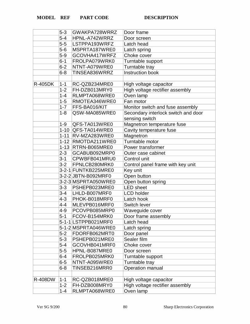
MODEL REF PART CODE DESCRIPTION
Ver SG 9/200 80 Sharp Electronics Corporation
5-3 GWAKPA728WRRZ Door frame5-4 HPNL-A742WRRZ Door screen5-5 LSTPPA193WRFZ Latch head5-6 MSPRTA187WRE0 Latch spring5-9 GCOVHA417WRFZ Choke cover6-1 FROLPA079WRK0 Turntable support6-2 NTNT-A079WRE0 Turntable tray6-8 TINSEA836WRRZ Instruction book
R-405DK 1-1 RC-QZB234MRE0 High voltage capacitor1-2 FH-DZB013MRY0 High voltage rectifier assembly1-4 RLMPTA068WRE0 Oven lamp1-5 RMOTEA346WRE0 Fan motor1-7 FFS-BA016/KIT Monitor switch and fuse assembly1-8 QSW-MA085WRE0 Secondary interlock switch and door
sensing switch1-9 QFS-TA013WRE0 Magnetron temperature fuse1-10 QFS-TA014WRE0 Cavity temperature fuse1-11 RV-MZA283WRE0 Magnetron1-12 RMOTDA211WRE0 Turntable motor1-13 RTRN-B065MRE0 Power transformer2-3 GCABUB092MRP0 Outer case cabinet3-1 CPWBFB041MRU0 Control unit3-2 FPNLCB280MRK0 Control panel frame with key unit3-2-1 FUNTKB225MRE0 Key unit3-2-2 JBTN-B092MRF0 Open button3-2-3 MSPRTA050WRE0 Open button spring3-3 PSHEPB023MRE0 LED sheet3-4 LHLD-B007MRF0 LCD holder4-3 PHOK-B018MRF0 Latch hook4-4 MLEVPB016MRF0 Switch lever4-9 PCOVPB085MRP0 Waveguide cover5-1 FCOV-B154MRK0 Door frame assembly5-1-1 LSTPPB021MRF0 Latch head5-1-2 MSPRTA046WRE0 Latch spring5-2 FDORFB062MRT0 Door panel5-3 PSHEPB021MRE0 Sealer film5-4 GCOVHB041MRF0 Choke cover5-5 HPNL-B087MRE0 Door screen6-4 FROLPB025MRK0 Turntable support6-5 NTNT-A095WRE0 Turntable tray6-8 TINSEB216MRR0 Operation manual
R-408DW 1-1 RC-QZB018MRE0 High voltage capacitor1-2 FH-DZB008MRY0 High voltage rectifier assembly1-4 RLMPTA068WRE0 Oven lamp
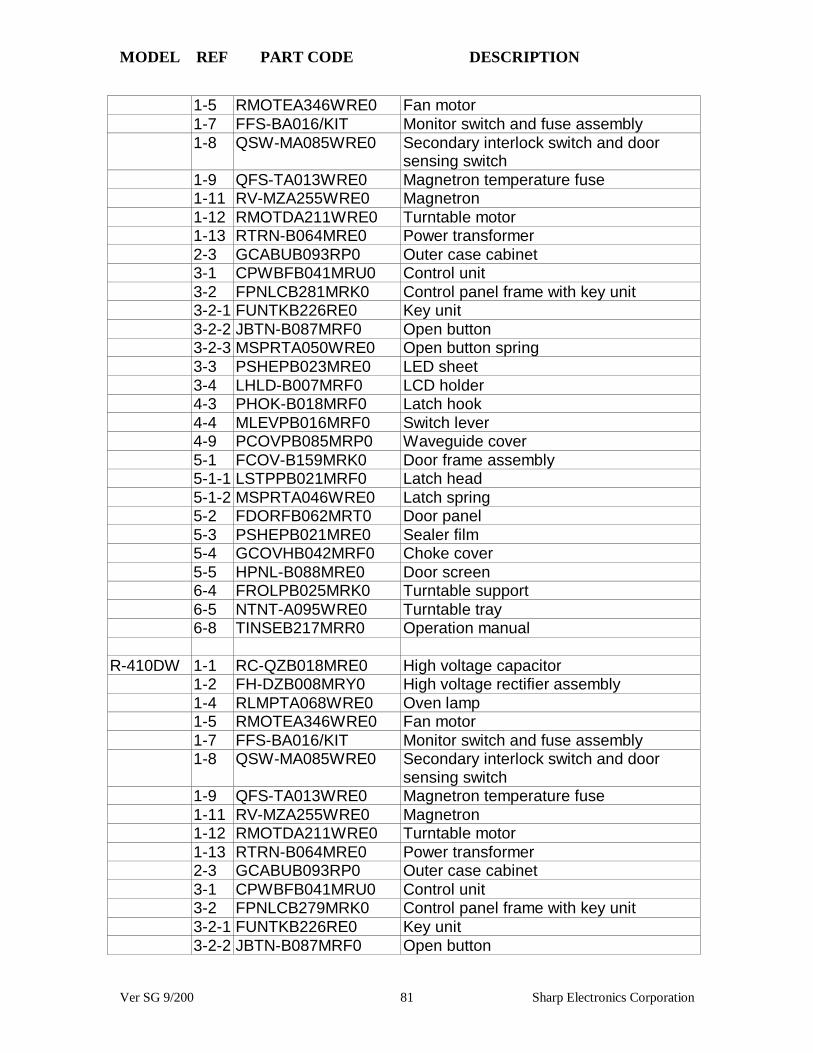
MODEL REF PART CODE DESCRIPTION
Ver SG 9/200 81 Sharp Electronics Corporation
1-5 RMOTEA346WRE0 Fan motor1-7 FFS-BA016/KIT Monitor switch and fuse assembly1-8 QSW-MA085WRE0 Secondary interlock switch and door
sensing switch1-9 QFS-TA013WRE0 Magnetron temperature fuse1-11 RV-MZA255WRE0 Magnetron1-12 RMOTDA211WRE0 Turntable motor1-13 RTRN-B064MRE0 Power transformer2-3 GCABUB093RP0 Outer case cabinet3-1 CPWBFB041MRU0 Control unit3-2 FPNLCB281MRK0 Control panel frame with key unit3-2-1 FUNTKB226RE0 Key unit3-2-2 JBTN-B087MRF0 Open button3-2-3 MSPRTA050WRE0 Open button spring3-3 PSHEPB023MRE0 LED sheet3-4 LHLD-B007MRF0 LCD holder4-3 PHOK-B018MRF0 Latch hook4-4 MLEVPB016MRF0 Switch lever4-9 PCOVPB085MRP0 Waveguide cover5-1 FCOV-B159MRK0 Door frame assembly5-1-1 LSTPPB021MRF0 Latch head5-1-2 MSPRTA046WRE0 Latch spring5-2 FDORFB062MRT0 Door panel5-3 PSHEPB021MRE0 Sealer film5-4 GCOVHB042MRF0 Choke cover5-5 HPNL-B088MRE0 Door screen6-4 FROLPB025MRK0 Turntable support6-5 NTNT-A095WRE0 Turntable tray6-8 TINSEB217MRR0 Operation manual
R-410DW 1-1 RC-QZB018MRE0 High voltage capacitor1-2 FH-DZB008MRY0 High voltage rectifier assembly1-4 RLMPTA068WRE0 Oven lamp1-5 RMOTEA346WRE0 Fan motor1-7 FFS-BA016/KIT Monitor switch and fuse assembly1-8 QSW-MA085WRE0 Secondary interlock switch and door
sensing switch1-9 QFS-TA013WRE0 Magnetron temperature fuse1-11 RV-MZA255WRE0 Magnetron1-12 RMOTDA211WRE0 Turntable motor1-13 RTRN-B064MRE0 Power transformer2-3 GCABUB093RP0 Outer case cabinet3-1 CPWBFB041MRU0 Control unit3-2 FPNLCB279MRK0 Control panel frame with key unit3-2-1 FUNTKB226RE0 Key unit3-2-2 JBTN-B087MRF0 Open button
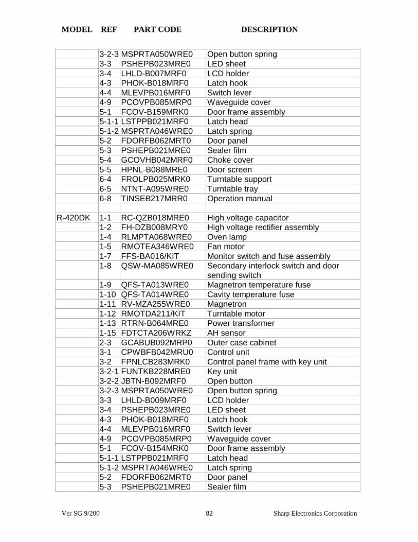
MODEL REF PART CODE DESCRIPTION
Ver SG 9/200 82 Sharp Electronics Corporation
3-2-3 MSPRTA050WRE0 Open button spring3-3 PSHEPB023MRE0 LED sheet3-4 LHLD-B007MRF0 LCD holder4-3 PHOK-B018MRF0 Latch hook4-4 MLEVPB016MRF0 Switch lever4-9 PCOVPB085MRP0 Waveguide cover5-1 FCOV-B159MRK0 Door frame assembly5-1-1 LSTPPB021MRF0 Latch head5-1-2 MSPRTA046WRE0 Latch spring5-2 FDORFB062MRT0 Door panel5-3 PSHEPB021MRE0 Sealer film5-4 GCOVHB042MRF0 Choke cover5-5 HPNL-B088MRE0 Door screen6-4 FROLPB025MRK0 Turntable support6-5 NTNT-A095WRE0 Turntable tray6-8 TINSEB217MRR0 Operation manual
R-420DK 1-1 RC-QZB018MRE0 High voltage capacitor1-2 FH-DZB008MRY0 High voltage rectifier assembly1-4 RLMPTA068WRE0 Oven lamp1-5 RMOTEA346WRE0 Fan motor1-7 FFS-BA016/KIT Monitor switch and fuse assembly1-8 QSW-MA085WRE0 Secondary interlock switch and door
sending switch1-9 QFS-TA013WRE0 Magnetron temperature fuse1-10 QFS-TA014WRE0 Cavity temperature fuse1-11 RV-MZA255WRE0 Magnetron1-12 RMOTDA211/KIT Turntable motor1-13 RTRN-B064MRE0 Power transformer1-15 FDTCTA206WRKZ AH sensor2-3 GCABUB092MRP0 Outer case cabinet3-1 CPWBFB042MRU0 Control unit3-2 FPNLCB283MRK0 Control panel frame with key unit3-2-1 FUNTKB228MRE0 Key unit3-2-2 JBTN-B092MRF0 Open button3-2-3 MSPRTA050WRE0 Open button spring3-3 LHLD-B009MRF0 LCD holder3-4 PSHEPB023MRE0 LED sheet4-3 PHOK-B018MRF0 Latch hook4-4 MLEVPB016MRF0 Switch lever4-9 PCOVPB085MRP0 Waveguide cover5-1 FCOV-B154MRK0 Door frame assembly5-1-1 LSTPPB021MRF0 Latch head5-1-2 MSPRTA046WRE0 Latch spring5-2 FDORFB062MRT0 Door panel5-3 PSHEPB021MRE0 Sealer film

MODEL REF PART CODE DESCRIPTION
Ver SG 9/200 83 Sharp Electronics Corporation
5-4 GCOVHB042MRF0 Choke cover5-5 HPNL-B087MRE0 Door screen6-4 FROLPB025MRK0 Turntable support6-5 NTNT-A095WRE0 Turntable tray6-8 TINSEB219MRR0 Operation manual
R-420DW 1-1 RC-QZB018MRE0 High voltage capacitor1-2 FH-DZB008MRY0 High voltage rectifier assembly1-4 RLMPTA068WRE0 Oven lamp1-5 RMOTEA346WRE0 Fan motor1-7 FFS-BA016/KIT Monitor switch and fuse assembly1-8 QSW-MA085WRE0 Secondary interlock switch and door
sending switch1-9 QFS-TA013WRE0 Magnetron temperature fuse1-10 QFS-TA014WRE0 Cavity temperature fuse1-11 RV-MZA255WRE0 Magnetron1-12 RMOTDA211/KIT Turntable motor1-13 RTRN-B064MRE0 Power transformer1-15 FDTCTA206WRKZ AH sensor2-3 GCABUB088MRP0 Outer case cabinet3-1 CPWBFB042MRU0 Control unit3-2 FPNLCB284MRK0 Control panel frame with key unit3-2-1 FUNTKB229MRE0 Key unit3-2-2 JBTN-B087MRF0 Open button3-2-3 MSPRTA050WRE0 Open button spring3-3 LHLD-B009MRF0 LCD holder3-4 PSHEPB023MRE0 LED sheet4-3 PHOK-B018MRF0 Latch hook4-4 MLEVPB016MRF0 Switch lever4-9 PCOVPB085MRP0 Waveguide cover5-1 FCOV-B159MRK0 Door frame assembly5-1-1 LSTPPB021MRF0 Latch head5-1-2 MSPRTA046WRE0 Latch spring5-2 FDORFB062MRT0 Door panel5-3 PSHEPB021MRE0 Sealer film5-4 GCOVHB042MRF0 Choke cover5-5 HPNL-B088MRE0 Door screen6-4 FROLPB025MRK0 Turntable support6-5 NTNT-A095WRE0 Turntable tray6-8 TINSEB219MRR0 Operation manual
R-419CK 1-1 RC-QZB018MRE0 High voltage capacitor1-2 FH-DZB013MRY0 High voltage rectifier assembly1-4 RLMPTA068WRE0 Oven lamp1-5 RMOTEA346WRE0 Fan motor1-7 FFS-BA016/KIT Monitor switch and fuse assembly

MODEL REF PART CODE DESCRIPTION
Ver SG 9/200 84 Sharp Electronics Corporation
1-8 QSW-MA085WRE0 Secondary interlock switch and doorsensing switch
1-9 QFS-TA013WRE0 Magnetron temperature fuse1-10 QFS-TA014WRE0 Cavity temperature fuse1-11 RV-MZA290WRE0 Magnetron1-12 RMOTDA211/KIT Turntable motor1-13 RTRN-B065MRE0 Power transformer1-15 FDTCTA198WRK0 AH sensor2-3 GCABUB097MRP0 Outer case cabinet3-1 CPWBFB031MRU0 Control unit3-2 FPNLCB311MRK0 Control panel frame with key unit3-2-1 FUNTKB192MRE0 Key unit3-2-2 JBTN-B092MRF0 Open button3-2-3 MSPRTA050WRE0 Open button spring3-3 LHLD-B009MRF0 LCD holder3-4 PSHEPB023MRE0 LED sheet4-3 PHOK-B018MRF0 Latch hook4-4 MLEVPB016MRF0 Switch lever4-9 PCOVPB073MRP0 Waveguide cover5-1 FCOV-B154MRK0 Door frame assembly5-1-1 LSTPPB021MRF0 Latch head5-1-2 MSPRTA046WRE0 Latch spring5-2 FDORFB062MRT0 Door panel5-3 PSHEPB021MRE0 Sealer film5-4 GCOVHB041MRF0 Choke cover5-5 HPNL-B087MRE0 Door screen6-4 FROLPB025MRK0 Turntable support6-5 NTNT-A095WRE0 Turntable tray6-8 TINSEB222MRR0 Operation manual
R-430DK 1-1 RC-QZB018MRE0 High voltage capacitor1-2 FH-DZB008MRY0 High voltage rectifier assembly1-4 RLMPTA068WRE0 Oven lamp1-5 RMOTEA346WRE0 Fan motor1-7 FFS-BA016/KIT Monitor switch and fuse assembly1-8 QSW-MA085WRE0 Secondary interlock switch and door
sensing switch1-9 QFS-TA013WRE0 Magnetron temperature fuse1-10 QFS-TA014WRE0 Cavity temperature fuse1-11 RV-MZA255WRE0 Magnetron1-12 RMOTDA211/KIT Turntable motor1-13 RTRN-B064MRE0 Power transformer1-15 FDTCTA198WRK0 AH sensor2-3 GCABUB092MRP0 Outer case cabinet3-1 CPWBFB043MRU0 Control unit3-2 FPNLCB285MRK0 Control panel frame with key unit
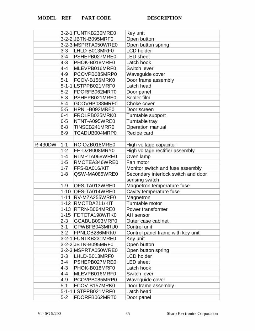
MODEL REF PART CODE DESCRIPTION
Ver SG 9/200 85 Sharp Electronics Corporation
3-2-1 FUNTKB230MRE0 Key unit3-2-2 JBTN-B095MRF0 Open button3-2-3 MSPRTA050WRE0 Open button spring3-3 LHLD-B013MRF0 LCD holder3-4 PSHEPB027MRE0 LED sheet4-3 PHOK-B018MRF0 Latch hook4-4 MLEVPB016MRF0 Switch lever4-9 PCOVPB085MRP0 Waveguide cover5-1 FCOV-B156MRK0 Door frame assembly5-1-1 LSTPPB021MRF0 Latch head5-2 FDORFB062MRT0 Door panel5-3 PSHEPB021MRE0 Sealer film5-4 GCOVHB038MRF0 Choke cover5-5 HPNL-B092MRE0 Door screen6-4 FROLPB025MRK0 Turntable support6-5 NTNT-A095WRE0 Turntable tray6-8 TINSEB241MRR0 Operation manual6-9 TCADUB004MRP0 Recipe card
R-430DW 1-1 RC-QZB018MRE0 High voltage capacitor1-2 FH-DZB008MRY0 High voltage rectifier assembly1-4 RLMPTA068WRE0 Oven lamp1-5 RMOTEA346WRE0 Fan motor1-7 FFS-BA016/KIT Monitor switch and fuse assembly1-8 QSW-MA085WRE0 Secondary interlock switch and door
sensing switch1-9 QFS-TA013WRE0 Magnetron temperature fuse1-10 QFS-TA014WRE0 Cavity temperature fuse1-11 RV-MZA255WRE0 Magnetron1-12 RMOTDA211/KIT Turntable motor1-13 RTRN-B064MRE0 Power transformer1-15 FDTCTA198WRK0 AH sensor2-3 GCABUB093MRP0 Outer case cabinet3-1 CPWBFB043MRU0 Control unit3-2 FPNLCB286MRK0 Control panel frame with key unit3-2-1 FUNTKB231MRE0 Key unit3-2-2 JBTN-B095MRF0 Open button3-2-3 MSPRTA050WRE0 Open button spring3-3 LHLD-B013MRF0 LCD holder3-4 PSHEPB027MRE0 LED sheet4-3 PHOK-B018MRF0 Latch hook4-4 MLEVPB016MRF0 Switch lever4-9 PCOVPB085MRP0 Waveguide cover5-1 FCOV-B157MRK0 Door frame assembly5-1-1 LSTPPB021MRF0 Latch head5-2 FDORFB062MRT0 Door panel

MODEL REF PART CODE DESCRIPTION
Ver SG 9/200 86 Sharp Electronics Corporation
5-3 PSHEPB021MRE0 Sealer film5-4 GCOVHB038MRF0 Choke cover5-5 HPNL-B092MRE0 Door screen6-4 FROLPB025MRK0 Turntable support6-5 NTNT-A095WRE0 Turntable tray6-8 TINSEB241MRR0 Operation manual6-9 TCADUB004MRP0 Recipe card
R-430DQ 1-1 RC-QZB018MRE0 High voltage capacitor1-2 FH-DZB008MRY0 High voltage rectifier assembly1-4 RLMPTA068WRE0 Oven lamp1-5 RMOTEA346WRE0 Fan motor1-7 FFS-BA016/KIT Monitor switch and fuse assembly1-8 QSW-MA085WRE0 Secondary interlock switch and door
sensing switch1-9 QFS-TA013WRE0 Magnetron temperature fuse1-10 QFS-TA014WRE0 Cavity temperature fuse1-11 RV-MZA255WRE0 Magnetron1-12 RMOTDA211/KIT Turntable motor1-13 RTRN-B064MRE0 Power transformer1-15 FDTCTA198WRK0 AH sensor2-3 GCABUB094MRP0 Outer case cabinet3-1 CPWBFB043MRU0 Control unit3-2 FPNLCB287MRK0 Control panel frame with key unit3-2-1 FUNTKB232MRE0 Key unit3-2-2 JBTN-B096MRF0 Open button3-2-3 MSPRTA050WRE0 Open button spring3-3 LHLD-B013MRF0 LCD holder3-4 PSHEPB027MRE0 LED sheet4-3 PHOK-B018MRF0 Latch hook4-4 MLEVPB016MRF0 Switch lever4-9 PCOVPB085MRP0 Waveguide cover5-1 FCOV-B158MRK0 Door frame assembly5-1-1 LSTPPB021MRF0 Latch head5-2 FDORFB062MRT0 Door panel5-3 PSHEPB021MRE0 Sealer film5-4 GCOVHB038MRF0 Choke cover5-5 HPNL-B094MRE0 Door screen6-4 FROLPB025MRK0 Turntable support6-5 NTNT-A095WRE0 Turntable tray6-8 TINSEB241MRR0 Operation manual6-9 TCADUB004MRP0 Recipe card
R-440DK 1-1 RC-QZB018MRE0 High voltage capacitor1-2 FH-DZB008MRY0 High voltage rectifier assembly
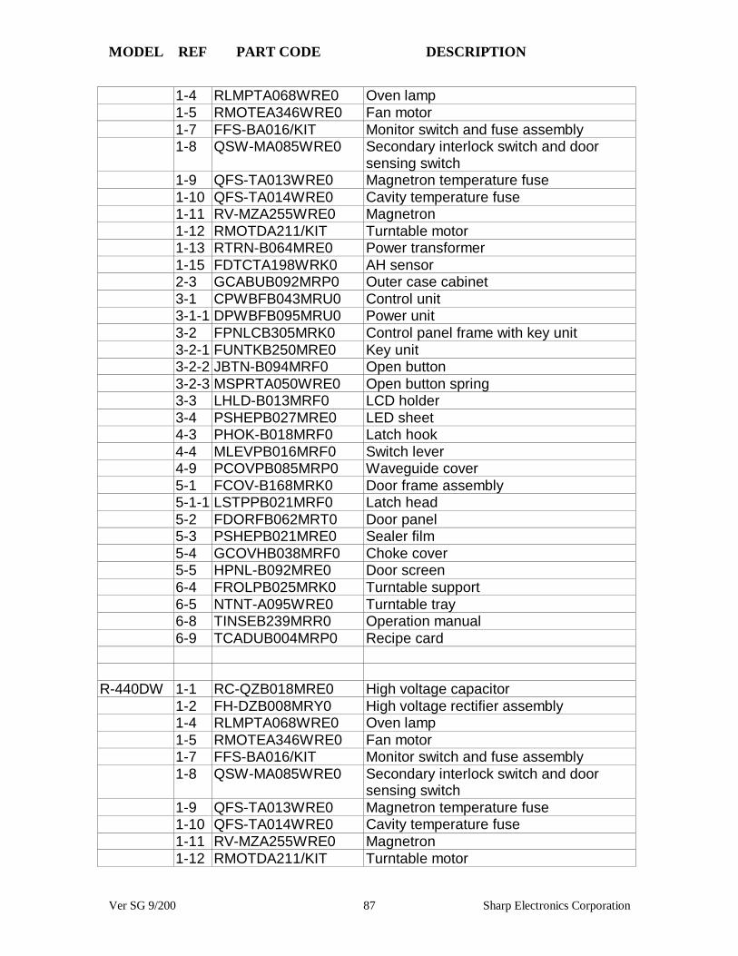
MODEL REF PART CODE DESCRIPTION
Ver SG 9/200 87 Sharp Electronics Corporation
1-4 RLMPTA068WRE0 Oven lamp1-5 RMOTEA346WRE0 Fan motor1-7 FFS-BA016/KIT Monitor switch and fuse assembly1-8 QSW-MA085WRE0 Secondary interlock switch and door
sensing switch1-9 QFS-TA013WRE0 Magnetron temperature fuse1-10 QFS-TA014WRE0 Cavity temperature fuse1-11 RV-MZA255WRE0 Magnetron1-12 RMOTDA211/KIT Turntable motor1-13 RTRN-B064MRE0 Power transformer1-15 FDTCTA198WRK0 AH sensor2-3 GCABUB092MRP0 Outer case cabinet3-1 CPWBFB043MRU0 Control unit3-1-1 DPWBFB095MRU0 Power unit3-2 FPNLCB305MRK0 Control panel frame with key unit3-2-1 FUNTKB250MRE0 Key unit3-2-2 JBTN-B094MRF0 Open button3-2-3 MSPRTA050WRE0 Open button spring3-3 LHLD-B013MRF0 LCD holder3-4 PSHEPB027MRE0 LED sheet4-3 PHOK-B018MRF0 Latch hook4-4 MLEVPB016MRF0 Switch lever4-9 PCOVPB085MRP0 Waveguide cover5-1 FCOV-B168MRK0 Door frame assembly5-1-1 LSTPPB021MRF0 Latch head5-2 FDORFB062MRT0 Door panel5-3 PSHEPB021MRE0 Sealer film5-4 GCOVHB038MRF0 Choke cover5-5 HPNL-B092MRE0 Door screen6-4 FROLPB025MRK0 Turntable support6-5 NTNT-A095WRE0 Turntable tray6-8 TINSEB239MRR0 Operation manual6-9 TCADUB004MRP0 Recipe card
R-440DW 1-1 RC-QZB018MRE0 High voltage capacitor1-2 FH-DZB008MRY0 High voltage rectifier assembly1-4 RLMPTA068WRE0 Oven lamp1-5 RMOTEA346WRE0 Fan motor1-7 FFS-BA016/KIT Monitor switch and fuse assembly1-8 QSW-MA085WRE0 Secondary interlock switch and door
sensing switch1-9 QFS-TA013WRE0 Magnetron temperature fuse1-10 QFS-TA014WRE0 Cavity temperature fuse1-11 RV-MZA255WRE0 Magnetron1-12 RMOTDA211/KIT Turntable motor

MODEL REF PART CODE DESCRIPTION
Ver SG 9/200 88 Sharp Electronics Corporation
1-13 RTRN-B064MRE0 Power transformer1-15 FDTCTA198WRK0 AH sensor2-3 GCABUB093MRP0 Outer case cabinet3-1 CPWBFB044MRU0 Control unit3-1-1 DPWBFB095MRU0 Power unit3-2 FPNLCB306MRK0 Control panel frame with key unit3-2-1 FUNTKB251MRE0 Key unit3-2-2 JBTN-B095MRF0 Open button3-2-3 MSPRTA050WRE0 Open button spring3-3 LHLD-B013MRF0 LCD holder3-4 PSHEPB027MRE0 LED sheet4-3 PHOK-B018MRF0 Latch hook4-4 MLEVPB016MRF0 Switch lever4-9 PCOVPB085MRP0 Waveguide cover5-1 FCOV-B169MRK0 Door frame assembly5-1-1 LSTPPB021MRF0 Latch head5-2 FDORFB062MRT0 Door panel5-3 PSHEPB021MRE0 Sealer film5-4 GCOVHB038MRF0 Choke cover5-5 HPNL-B093MRE0 Door screen6-4 FROLPB025MRK0 Turntable support6-5 NTNT-A095WRE0 Turntable tray6-8 TINSEB239MRR0 Operation manual6-9 TCADUB004MRP0 Recipe card
R-508DK 1-1 RC-QZB018MRE0 High voltage capacitor1-2 FH-DZB008MRY0 High voltage rectifier assembly1-4 RLMPTA068WRE0 Oven lamp1-5 RMOTEA346WRE0 Fan motor1-7 FFS-BA016/KIT Monitor switch and fuse assembly1-8 QSW-MA085WRE0 Secondary interlock switch and door
sensing switch1-9 QFS-TA013WRE0 Magnetron temperature fuse1-10 QFS-TA014WRE0 Cavity temperature fuse1-11 RV-MZA255WRE0 Magnetron1-12 RMOTDA229WRE0 Turntable motor1-13 RTRN-B064MRE0 Power transformer2-3 GCABUB096MRP0 Outer case cabinet3-1 CPWBFB041MRU0 Control unit3-2 FPNLCB295MRK0 Control panel frame with key unit3-2-1 FUNTKB240MRE0 Key unit3-2-2 JBTN-B093MRF0 Open button3-2-3 MSPRTA050WRE0 Open button spring3-3 PSHEPB023MRE0 LED sheet

MODEL REF PART CODE DESCRIPTION
Ver SG 9/200 89 Sharp Electronics Corporation
3-4 LHLD-B007MRF0 LCD holder4-3 PHOK-B018MRF0 Latch hook4-4 MLEVPB016MRF0 Switch lever4-9 PCOVPB085MRP0 Waveguide cover5-1 FCOV-B155MRK0 Door frame assembly5-1-1 LSTPPB021MRF0 Latch head5-1-2 MSPRTA046WRE0 Latch spring5-2 FDORFB049MRT0 Door panel5-3 PSHEPB016MRE0 Sealer film5-4 GCOVHB039MRF0 Choke cover5-5 HPNL-B089MRE0 Door screen6-4 FROLPB025MRK0 Turntable support6-5 NTNT-A099WRE0 Turntable tray6-8 TINSEB217MRR0 Operation manual
R-510DK 1-1 RC-QZB018MRE0 High voltage capacitor1-2 FH-DZB008MRY0 High voltage rectifier assembly1-4 RLMPTA068WRE0 Oven lamp1-5 RMOTEA346WRE0 Fan motor1-7 FFS-BA016/KIT Monitor switch and fuse assembly1-8 QSW-MA085WRE0 Secondary interlock switch and door
sensing switch1-9 QFS-TA013WRE0 Magnetron temperature fuse1-10 QFS-TA014WRE0 Cavity temperature fuse1-11 RV-MZA255WRE0 Magnetron1-12 RMOTDA229WRE0 Turntable motor1-13 RTRN-B064MRE0 Power transformer2-3 GCABUB096MRP0 Outer case cabinet3-1 CPWBFB041MRU0 Control unit3-2 FPNLCB293MRK0 Control panel frame with key unit3-2-1 FUNTKB238MRE0 Key unit3-2-2 JBTN-B093MRF0 Open button3-2-3 MSPRTA050WRE0 Open button spring3-3 PSHEPB023MRE0 LED sheet3-4 LHLD-B007MRF0 LCD holder4-3 PHOK-B018MRF0 Latch hook4-4 MLEVPB016MRF0 Switch lever4-9 PCOVPB085MRP0 Waveguide cover5-1 FCOV-B155MRK0 Door frame assembly5-1-1 LSTPPB021MRF0 Latch head5-1-2 MSPRTA046WRE0 Latch spring5-2 FDORFB049MRT0 Door panel5-3 PSHEPB016MRE0 Sealer film5-4 GCOVHB039MRF0 Choke cover5-5 HPNL-B089MRE0 Door screen6-4 FROLPB025MRK0 Turntable support
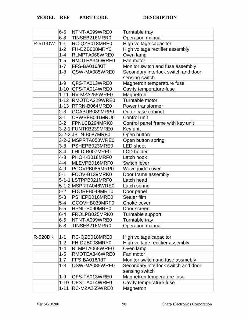
MODEL REF PART CODE DESCRIPTION
Ver SG 9/200 90 Sharp Electronics Corporation
6-5 NTNT-A099WRE0 Turntable tray6-8 TINSEB216MRR0 Operation manual
R-510DW 1-1 RC-QZB018MRE0 High voltage capacitor1-2 FH-DZB008MRY0 High voltage rectifier assembly1-4 RLMPTA068WRE0 Oven lamp1-5 RMOTEA346WRE0 Fan motor1-7 FFS-BA016/KIT Monitor switch and fuse assembly1-8 QSW-MA085WRE0 Secondary interlock switch and door
sensing switch1-9 QFS-TA013WRE0 Magnetron temperature fuse1-10 QFS-TA014WRE0 Cavity temperature fuse1-11 RV-MZA255WRE0 Magnetron1-12 RMOTDA229WRE0 Turntable motor1-13 RTRN-B064MRE0 Power transformer2-3 GCABUB089MRP0 Outer case cabinet3-1 CPWBFB041MRU0 Control unit3-2 FPNLCB294MRK0 Control panel frame with key unit3-2-1 FUNTKB239MRE0 Key unit3-2-2 JBTN-B087MRF0 Open button3-2-3 MSPRTA050WRE0 Open button spring3-3 PSHEPB023MRE0 LED sheet3-4 LHLD-B007MRF0 LCD holder4-3 PHOK-B018MRF0 Latch hook4-4 MLEVPB016MRF0 Switch lever4-9 PCOVPB085MRP0 Waveguide cover5-1 FCOV-B139MRK0 Door frame assembly5-1-1 LSTPPB021MRF0 Latch head5-1-2 MSPRTA046WRE0 Latch spring5-2 FDORFB049MRT0 Door panel5-3 PSHEPB016MRE0 Sealer film5-4 GCOVHB039MRF0 Choke cover5-5 HPNL-B090MRE0 Door screen6-4 FROLPB025MRK0 Turntable support6-5 NTNT-A099WRE0 Turntable tray6-8 TINSEB216MRR0 Operation manual
R-520DK 1-1 RC-QZB018MRE0 High voltage capacitor1-2 FH-DZB008MRY0 High voltage rectifier assembly1-4 RLMPTA068WRE0 Oven lamp1-5 RMOTEA346WRE0 Fan motor1-7 FFS-BA016/KIT Monitor switch and fuse assmebly1-8 QSW-MA085WRE0 Secondary interlock switch and door
sensing switch1-9 QFS-TA013WRE0 Magnetron temperature fuse1-10 QFS-TA014WRE0 Cavity temperature fuse1-11 RC-MZA255WRE0 Magnetron

MODEL REF PART CODE DESCRIPTION
Ver SG 9/200 91 Sharp Electronics Corporation
1-11 RV-MZA293WRE0 Magnetron (interchangeable)1-12 RMOTDA229WRE0 Turntable motor1-13 RTRN-B064MRE0 Power transformer1-15 FDTCTA206WRKZ AH sensor2-3 GCABUB096MRP0 Outer case cabinet3-1 CPWBFB042MRU0 Control unit3-2 FPNLCB299MRK0 Control panel frame with key unit3-2-1 FUNTKB244MRE0 Key unit3-2-2 JBTN-B092MRF0 Open button3-2-3 MSPRTA050WRE0 Open button spring3-3 LHLD-B009MRF0 LCD holder3-4 PSHEPB023MRE0 LED sheet4-3 PHOK-B018MRF0 Latch hook4-4 MLEVPB016MRF0 Switch lever4-9 PCOVPB085MRP0 Waveguide cover5-1 FCOV-B155MRK0 Door frame assembly5-1-1 LSTPPB021MRF0 Latch head5-1-2 MSPRTA046WRE0 Latch spring5-2 FDORFB049MRT0 Door panel5-3 PSHEPB016MRE0 Sealer film5-4 GCOVHB039MRF0 Choke cover5-5 HPNL-B089MRE0 Door screen6-4 FROLPB025MRK0 Turntable support6-5 NTNT-A099WRE0 Turntable tray6-8 TINSEB219MRR0 Operation manual6-10 TCADUB004MRR0 Recipe card
R-520DW 1-1 RC-QZB018MRE0 High voltage capacitor1-2 FH-DZB008MRY0 High voltage rectifier assembly1-4 RLMPTA068WRE0 Oven lamp1-5 RMOTEA346WRE0 Fan motor1-7 FFS-BA016/KIT Monitor switch and fuse assmebly1-8 QSW-MA085WRE0 Secondary interlock switch and door
sensing switch1-9 QFS-TA013WRE0 Magnetron temperature fuse1-10 QFS-TA014WRE0 Cavity temperature fuse1-11 RC-MZA255WRE0 Magnetron1-11 RV-MZA293WRE0 Magnetron (interchangeable)1-12 RMOTDA229WRE0 Turntable motor1-13 RTRN-B064MRE0 Power transformer1-15 FDTCTA206WRKZ AH sensor2-3 GCABUB089MRP0 Outer case cabinet3-1 CPWBFB042MRU0 Control unit3-2 FPNLCB299MRK0 Control panel frame with key unit3-2-1 FUNTKB245MRE0 Key unit3-2-2 JBTN-B087MRF0 Open button

MODEL REF PART CODE DESCRIPTION
Ver SG 9/200 92 Sharp Electronics Corporation
3-2-3 MSPRTA050WRE0 Open button spring3-3 LHLD-B009MRF0 LCD holder3-4 PSHEPB023MRE0 LED sheet4-3 PHOK-B018MRF0 Latch hook4-4 MLEVPB016MRF0 Switch lever4-9 PCOVPB085MRP0 Waveguide cover5-1 FCOV-B139MRK0 Door frame assembly5-1-1 LSTPPB021MRF0 Latch head5-1-2 MSPRTA046WRE0 Latch spring5-2 FDORFB049MRT0 Door panel5-3 PSHEPB016MRE0 Sealer film5-4 GCOVHB039MRF0 Choke cover5-5 HPNL-B090MRE0 Door screen6-4 FROLPB025MRK0 Turntable support6-5 NTNT-A099WRE0 Turntable tray6-8 TINSEB219MRR0 Operation manual6-10 TCADUB004MRR0 Recipe card
R-530DK 1-1 RC-QZB018MRE0 High voltage capacitor1-2 FH-DZB008MRY0 High voltage rectifier assembly1-4 RLMPTA068WRE0 Oven lamp1-5 RMOTEA346WRE0 Fan motor1-7 FFS-BA016/KIT Monitor switch and fuse assmebly1-8 QSW-MA085WRE0 Secondary interlock switch and door
sensing switch1-9 QFS-TA013WRE0 Magnetron temperature fuse1-10 QFS-TA014WRE0 Cavity temperature fuse1-11 RC-MZA255WRE0 Magnetron1-11 RV-MZA293WRE0 Magnetron (interchangeable)1-12 RMOTDA229WRE0 Turntable motor1-13 RTRN-B064MRE0 Power transformer1-15 FDTCTA206WRKZ AH sensor2-3 GCABUB096MRP0 Outer case cabinet3-1 CPWBFB042MRU0 Control unit3-2 FPNLCB301MRK0 Control panel frame with key unit3-2-1 FUNTKB246MRE0 Key unit3-2-2 JBTN-B092MRF0 Open button3-2-3 MSPRTA050WRE0 Open button spring3-3 LHLD-B010MRF0 LCD holder3-4 PSHEPB027MRE0 LED sheet4-3 PHOK-B018MRF0 Latch hook4-4 MLEVPB016MRF0 Switch lever4-9 PCOVPB085MRP0 Waveguide cover5-1 FCOV-B155MRK0 Door frame assembly5-1-1 LSTPPB021MRF0 Latch head5-1-2 MSPRTA046WRE0 Latch spring
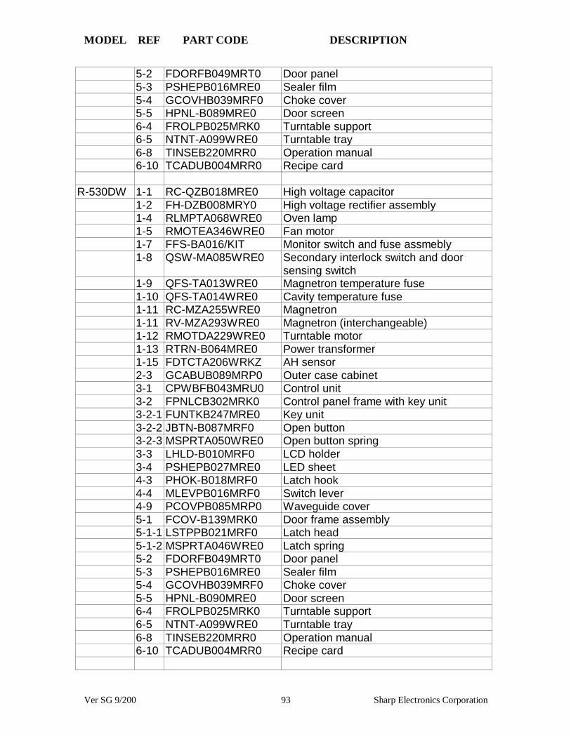
MODEL REF PART CODE DESCRIPTION
Ver SG 9/200 93 Sharp Electronics Corporation
5-2 FDORFB049MRT0 Door panel5-3 PSHEPB016MRE0 Sealer film5-4 GCOVHB039MRF0 Choke cover5-5 HPNL-B089MRE0 Door screen6-4 FROLPB025MRK0 Turntable support6-5 NTNT-A099WRE0 Turntable tray6-8 TINSEB220MRR0 Operation manual6-10 TCADUB004MRR0 Recipe card
R-530DW 1-1 RC-QZB018MRE0 High voltage capacitor1-2 FH-DZB008MRY0 High voltage rectifier assembly1-4 RLMPTA068WRE0 Oven lamp1-5 RMOTEA346WRE0 Fan motor1-7 FFS-BA016/KIT Monitor switch and fuse assmebly1-8 QSW-MA085WRE0 Secondary interlock switch and door
sensing switch1-9 QFS-TA013WRE0 Magnetron temperature fuse1-10 QFS-TA014WRE0 Cavity temperature fuse1-11 RC-MZA255WRE0 Magnetron1-11 RV-MZA293WRE0 Magnetron (interchangeable)1-12 RMOTDA229WRE0 Turntable motor1-13 RTRN-B064MRE0 Power transformer1-15 FDTCTA206WRKZ AH sensor2-3 GCABUB089MRP0 Outer case cabinet3-1 CPWBFB043MRU0 Control unit3-2 FPNLCB302MRK0 Control panel frame with key unit3-2-1 FUNTKB247MRE0 Key unit3-2-2 JBTN-B087MRF0 Open button3-2-3 MSPRTA050WRE0 Open button spring3-3 LHLD-B010MRF0 LCD holder3-4 PSHEPB027MRE0 LED sheet4-3 PHOK-B018MRF0 Latch hook4-4 MLEVPB016MRF0 Switch lever4-9 PCOVPB085MRP0 Waveguide cover5-1 FCOV-B139MRK0 Door frame assembly5-1-1 LSTPPB021MRF0 Latch head5-1-2 MSPRTA046WRE0 Latch spring5-2 FDORFB049MRT0 Door panel5-3 PSHEPB016MRE0 Sealer film5-4 GCOVHB039MRF0 Choke cover5-5 HPNL-B090MRE0 Door screen6-4 FROLPB025MRK0 Turntable support6-5 NTNT-A099WRE0 Turntable tray6-8 TINSEB220MRR0 Operation manual6-10 TCADUB004MRR0 Recipe card

MODEL REF PART CODE DESCRIPTION
Ver SG 9/200 94 Sharp Electronics Corporation
R-540DK 1-1 RC-QZB018MRE0 High voltage capacitor1-2 FH-DZB008MRY0 High voltage rectifier assembly1-4 RLMPTA068WRE0 Oven lamp1-5 RMOTEA346WRE0 Fan motor1-7 FFS-BA016/KIT Monitor switch and fuse assembly1-8 QSW-MA085WRE0 Secondary interlock switch and door
sensing switch1-9 QFS-TA013WRE0 Magnetron temperature fuse1-11 RV-MZA293WRE0 Magnetron1-12 RMOTDA229WRE0 Turntable motor1-13 RTRN-B064MRE0 Power transformer1-15 FDTCTA206WRKZ AH sensor2-3 GCABUB096MRP0 Outer case cabinet3-1 CPWBFB044MRU0 Control unit3-2 FPNLCB303MRK0 Control panel frame with key unit3-2-1 FUNTKB248MRE0 Key unit3-2-2 JBTN-B092MRF0 Open button3-2-3 MSPRTA050WRE0 Open button spring4-3 PHOK-B018MRF0 Latch hook4-4 MLEVPB016MRF0 Switch lever4-9 PCOVPB085MRP0 Waveguide cover5-1 FCOV-B170MRK0 Door frame assembly5-1-1 LSTPPB021MRF0 Latch head5-1-2 MSPRTA046WRE0 Latch spring5-2 FDORFB049MRT0 Door panel5-3 PSHEPB016MRE0 Sealer film5-4 GCOVHB039MRF0 Choke cover5-5 HPNL-B089MRE0 Door screen6-4 FROLPB025MRK0 Turntable support6-5 NTNT-A099WRE0 Turntable tray6-8 TINSEB224MRR0 Operation manual
R-540DW 1-1 RC-QZB018MRE0 High voltage capacitor1-2 FH-DZB008MRY0 High voltage rectifier assembly1-4 RLMPTA068WRE0 Oven lamp1-5 RMOTEA346WRE0 Fan motor1-7 FFS-BA016/KIT Monitor switch and fuse assembly1-8 QSW-MA085WRE0 Secondary interlock switch and door
sensing switch1-9 QFS-TA013WRE0 Magnetron temperature fuse1-11 RV-MZA293WRE0 Magnetron1-12 RMOTDA229WRE0 Turntable motor1-13 RTRN-B064MRE0 Power transformer

MODEL REF PART CODE DESCRIPTION
Ver SG 9/200 95 Sharp Electronics Corporation
1-15 FDTCTA206WRKZ AH sensor2-3 GCABUB089MRP0 Outer case cabinet3-1 CPWBFB044MRU0 Control unit3-2 FPNLCB304MRK0 Control panel frame with key unit3-2-1 FUNTKB249MRE0 Key unit3-2-2 JBTN-B087MRF0 Open button3-2-3 MSPRTA050WRE0 Open button spring4-3 PHOK-B018MRF0 Latch hook4-4 MLEVPB016MRF0 Switch lever4-9 PCOVPB085MRP0 Waveguide cover5-1 FCOV-B171MRK0 Door frame assembly5-1-1 LSTPPB021MRF0 Latch head5-1-2 MSPRTA046WRE0 Latch spring5-2 FDORFB049MRT0 Door panel5-3 PSHEPB016MRE0 Sealer film5-4 GCOVHB039MRF0 Choke cover5-5 HPNL-B090MRE0 Door screen6-4 FROLPB025MRK0 Turntable support6-5 NTNT-A099WRE0 Turntable tray6-8 TINSEB224MRR0 Operation manual
R-610DK 1-3 QSW-MA137WRE0 Secondary interlock switch / doorsensing switch
1-4 FFS-BA023WRK0 Monitor fuse 20 Amp and monitor switchassembly
1-5 RTHM-A116WRE0 Thermal cut-out1-6 FH-DZA097WRKZ High voltage rectifier assembly1-7 RC-QZA211WRE0 High voltage capacitor1-8 RMOTEA395WRZZ Fan motor1-9 RTRN-A609WRZZ Power transformer1-11 RLMPTA068WRE0 Oven lamp1-11 RLMPTA030WRE0 Oven lamp (interchangeable)1-12 RMOTDA229WRE0 Turntable motor1-12 RMOTDA211WRE0 Turntable motor (interchangeable)1-13 RTHM-A123WRZZ Thermal cut-out1-14 RV-MZA310WRZZ Magnetron2-4 GCABUA773WRPZ Outer case cabinet3-1 DPWBFC069WRUZ Power unit4-1 PHOK-A118WRFZ Latch hook4-13 GCOVHA419WRFZ Choke cover4-16 PCOVPA361WREZ Waveguide cover5-1 FDORFA343WRTZ Door panel5-2 PSHEPA735WREZ Sealer film5-3 FPNL-A040WRKZ Door screen assembly5-3-1 PSHEPA736WREZ Key sheet5-4 GWAKPA736WRFZ Door frame

MODEL REF PART CODE DESCRIPTION
Ver SG 9/200 96 Sharp Electronics Corporation
5-5 JHNDPA188WRTZ Handle5-7 LSTPPA193WRFZ Latch head5-8 MSPRTA187WRE0 Latch spring5-9 LHLD-A225WRFZ LCD holder5-17 PSHEPA588WRE0 LED sheet6-1 FROLPA095WRKZ Turntable support6-2 NTNT-A099WRE0 Turntable tray6-10 TINSEA845WRRZ Instruction book
R-610DS 1-3 QSW-MA137WRE0 Secondary interlock switch / doorsensing switch
1-4 FFS-BA023WRK0 Monitor fuse 20 Amp and monitor switchassembly
1-5 RTHM-A116WRE0 Thermal cut-out1-6 FH-DZA097WRKZ High voltage rectifier assembly1-7 RC-QZA211WRE0 High voltage capacitor1-8 RMOTEA395WRZZ Fan motor1-9 RTRN-A609WRZZ Power transformer1-11 RLMPTA068WRE0 Oven lamp1-11 RLMPTA030WRE0 Oven lamp (interchangeable)1-12 RMOTDA229WRE0 Turntable motor1-12 RMOTDA211WRE0 Turntable motor (interchangeable)1-13 RTHM-A123WRZZ Thermal cut-out1-14 RV-MZA310WRZZ Magnetron2-4 GCABUA777WRPZ Outer case cabinet3-1 DPWBFC069WRUZ Power unit4-1 PHOK-A118WRFZ Latch hook4-13 GCOVHA419WRFZ Choke cover4-16 PCOVPA361WREZ Waveguide cover5-1 FDORFA343WRTZ Door panel5-2 PSHEPA735WREZ Sealer film5-3 FPNL-A040WRKZ Door screen assembly5-3-1 PSHEPA736WREZ Key sheet5-4 GWAKPA736WRFZ Door frame5-5 JHNDPA186WRTZ Handle5-7 LSTPPA193WRFZ Latch head5-8 MSPRTA187WRE0 Latch spring5-9 LHLD-A225WRFZ LCD holder5-17 PSHEPA588WRE0 LED sheet6-1 FROLPA095WRKZ Turntable support6-2 NTNT-A099WRE0 Turntable tray6-10 TINSEA845WRRZ Instruction book
R-610DW 1-3 QSW-MA137WRE0 Secondary interlock switch / doorsensing switch
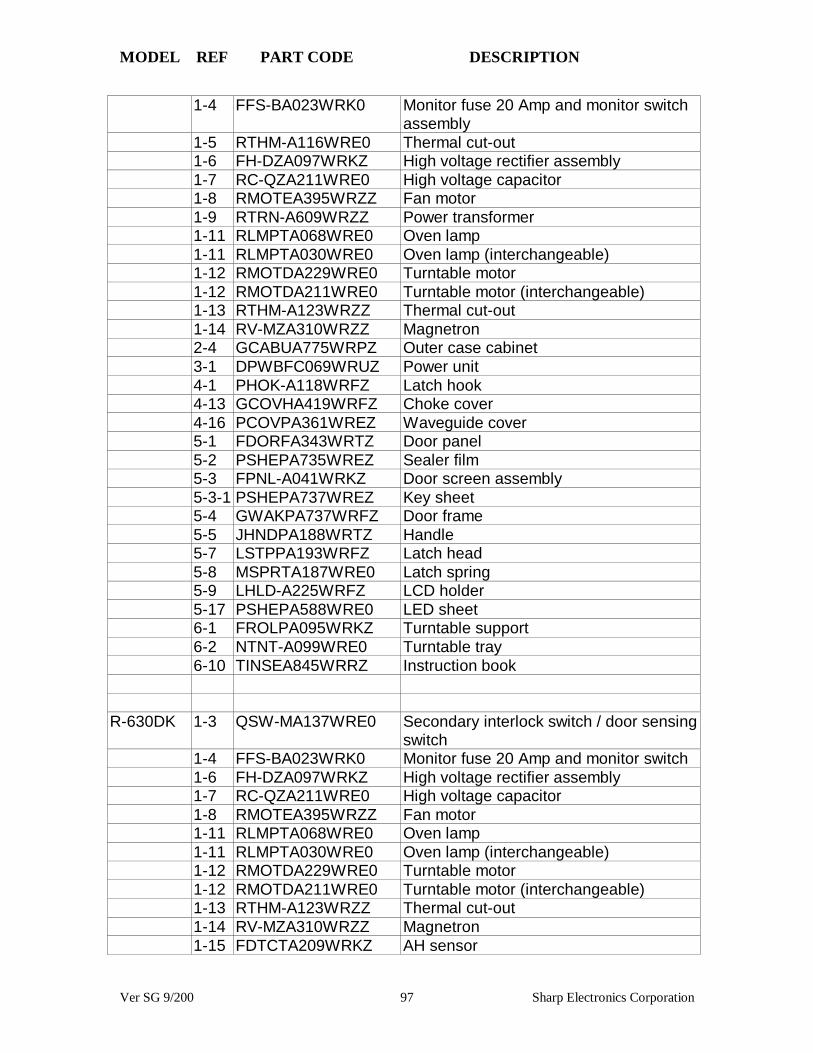
MODEL REF PART CODE DESCRIPTION
Ver SG 9/200 97 Sharp Electronics Corporation
1-4 FFS-BA023WRK0 Monitor fuse 20 Amp and monitor switchassembly
1-5 RTHM-A116WRE0 Thermal cut-out1-6 FH-DZA097WRKZ High voltage rectifier assembly1-7 RC-QZA211WRE0 High voltage capacitor1-8 RMOTEA395WRZZ Fan motor1-9 RTRN-A609WRZZ Power transformer1-11 RLMPTA068WRE0 Oven lamp1-11 RLMPTA030WRE0 Oven lamp (interchangeable)1-12 RMOTDA229WRE0 Turntable motor1-12 RMOTDA211WRE0 Turntable motor (interchangeable)1-13 RTHM-A123WRZZ Thermal cut-out1-14 RV-MZA310WRZZ Magnetron2-4 GCABUA775WRPZ Outer case cabinet3-1 DPWBFC069WRUZ Power unit4-1 PHOK-A118WRFZ Latch hook4-13 GCOVHA419WRFZ Choke cover4-16 PCOVPA361WREZ Waveguide cover5-1 FDORFA343WRTZ Door panel5-2 PSHEPA735WREZ Sealer film5-3 FPNL-A041WRKZ Door screen assembly5-3-1 PSHEPA737WREZ Key sheet5-4 GWAKPA737WRFZ Door frame5-5 JHNDPA188WRTZ Handle5-7 LSTPPA193WRFZ Latch head5-8 MSPRTA187WRE0 Latch spring5-9 LHLD-A225WRFZ LCD holder5-17 PSHEPA588WRE0 LED sheet6-1 FROLPA095WRKZ Turntable support6-2 NTNT-A099WRE0 Turntable tray6-10 TINSEA845WRRZ Instruction book
R-630DK 1-3 QSW-MA137WRE0 Secondary interlock switch / door sensingswitch
1-4 FFS-BA023WRK0 Monitor fuse 20 Amp and monitor switch1-6 FH-DZA097WRKZ High voltage rectifier assembly1-7 RC-QZA211WRE0 High voltage capacitor1-8 RMOTEA395WRZZ Fan motor1-11 RLMPTA068WRE0 Oven lamp1-11 RLMPTA030WRE0 Oven lamp (interchangeable)1-12 RMOTDA229WRE0 Turntable motor1-12 RMOTDA211WRE0 Turntable motor (interchangeable)1-13 RTHM-A123WRZZ Thermal cut-out1-14 RV-MZA310WRZZ Magnetron1-15 FDTCTA209WRKZ AH sensor

MODEL REF PART CODE DESCRIPTION
Ver SG 9/200 98 Sharp Electronics Corporation
2-4 GCABUA773WRPZ Outer case cabinet4-1 PHOK-A118WRFZ Latch hook4-13 GCOVHA419WRFZ Choke cover4-16 PCOVPA361WREZ Waveguide cover5-1 FDORFA343WRTZ Door panel5-2 PSHEPA735WREZ Sealer film5-3 FPNL-A042WRKZ Door screen assembly5-3-1 PSHEPA741WREZ Key sheet5-4 GWAKPA736WRFZ Door frame5-5 JHNDPA188WRTZ Handle5-7 LSTPPA193WRFZ Latch head5-8 MSPRTA187WRE0 Latch spring5-9 LHLD-A226WRFZ LCD holder5-17 PSHEPA672WRE0 LED sheet6-1 FROLPA095WRKZ Turntable support6-2 NTNT-A099WRE0 Turntable tray6-10 TINSEA863WRRZ Instruction book
R-630DS 1-3 QSW-MA137WRE0 Secondary interlock switch / door sensingswitch
1-4 FFS-BA023WRK0 Monitor fuse 20 Amp and monitor switch1-6 FH-DZA097WRKZ High voltage rectifier assembly1-7 RC-QZA211WRE0 High voltage capacitor1-8 RMOTEA395WRZZ Fan motor1-11 RLMPTA068WRE0 Oven lamp1-11 RLMPTA030WRE0 Oven lamp (interchangeable)1-12 RMOTDA229WRE0 Turntable motor1-12 RMOTDA211WRE0 Turntable motor (interchangeable)1-13 RTHM-A123WRZZ Thermal cut-out1-14 RV-MZA310WRZZ Magnetron1-15 FDTCTA209WRKZ AH sensor2-4 GCABUA777WRPZ Outer case cabinet4-1 PHOK-A118WRFZ Latch hook4-13 GCOVHA419WRFZ Choke cover4-16 PCOVPA361WREZ Waveguide cover5-1 FDORFA343WRTZ Door panel5-2 PSHEPA735WREZ Sealer film5-3 FPNL-A042WRKZ Door screen assembly5-3-1 PSHEPA741WREZ Key sheet5-4 GWAKPA738WRFZ Door frame5-5 JHNDPA186WRTZ Handle5-7 LSTPPA193WRFZ Latch head5-8 MSPRTA187WRE0 Latch spring5-9 LHLD-A226WRFZ LCD holder5-17 PSHEPA672WRE0 LED sheet6-1 FROLPA095WRKZ Turntable support

MODEL REF PART CODE DESCRIPTION
Ver SG 9/200 99 Sharp Electronics Corporation
6-2 NTNT-A099WRE0 Turntable tray6-10 TINSEA863WRRZ Instruction book
R-630DW 1-3 QSW-MA137WRE0 Secondary interlock switch / door sensingswitch
1-4 FFS-BA023WRK0 Monitor fuse 20 Amp and monitor switch1-6 FH-DZA097WRKZ High voltage rectifier assembly1-7 RC-QZA211WRE0 High voltage capacitor1-8 RMOTEA395WRZZ Fan motor1-11 RLMPTA068WRE0 Oven lamp1-11 RLMPTA030WRE0 Oven lamp (interchangeable)1-12 RMOTDA229WRE0 Turntable motor1-12 RMOTDA211WRE0 Turntable motor (interchangeable)1-13 RTHM-A123WRZZ Thermal cut-out1-14 RV-MZA310WRZZ Magnetron1-15 FDTCTA209WRKZ AH sensor2-4 GCABUA775WRPZ Outer case cabinet4-1 PHOK-A118WRFZ Latch hook4-13 GCOVHA419WRFZ Choke cover4-16 PCOVPA361WREZ Waveguide cover5-1 FDORFA343WRTZ Door panel5-2 PSHEPA735WREZ Sealer film5-3 FPNL-A043WRKZ Door screen assembly5-3-1 PSHEPA742WREZ Key sheet5-4 GWAKPA737WRFZ Door frame5-5 JHNDPA188WRTZ Handle5-7 LSTPPA193WRFZ Latch head5-8 MSPRTA187WRE0 Latch spring5-9 LHLD-A226WRFZ LCD holder5-17 PSHEPA672WRE0 LED sheet6-1 FROLPA095WRKZ Turntable support6-2 NTNT-A099WRE0 Turntable tray6-10 TINSEA863WRRZ Instruction book
R-1380 1-1 FH-DZB012MRY0 High voltage rectifier assembly1-2 RC-QZA234WRE0 High voltage capacitor1-3 QFS-TA013WRE0 Temperature fuse (magnetron)1-4 RMOTDA211WRE0 Turntable motor1-5 RMOTDA214WRE0 Stirrer motor1-6 RTHM-0044MRE0 Thermal cut-out (hood fan)1-7 RTRN-B062MRE0 Power transformer1-8 RV-MZA281WRE0 Magnetron1-10 QSW-MA085WRE0 Secondary interlock and door sensing
switches1-11 FFS-BA016/KIT Monitor switch with fuse assembly1-14 FMOTEA402WRK0 Hood fan motor

MODEL REF PART CODE DESCRIPTION
Ver SG 9/200 100 Sharp Electronics Corporation
1-15 RMOTEA346WRE0 Fan motor1-16 RLMPTA068WRE0 Oven lamp1-17 RTHM-A070WRE0 Thermal cut-out (cavity)2-2 PDIF-B018MRF0 Hood exhaust louver2-5 GCABUB084MRP0 Outer case cabinet2-7 FANGKB009MRY0 Hood lamp glass assembly2-7-2 PGLSPB004MRE0 Hood lamp glass3-1 DPWBFB081MRU0 Control unit3-2 FPNLCB205MRK0 Control panel sub. Assembly3-2-1 FUNTKB153MRE0 Key unit3-2-2 GMADIB030MRF0 Display window4-1 FFTA-B003MRK0 Exhaust damper assembly4-2 FROLPB025MRK0 Turntable support assembly4-3 NTNT-A090WRE0 Turntable tray4-5 FCOVPB016MRK0 Stirrer cover assembly4-6 FFAN-B009MRK0 Stirrer fan assembly4-9 PHOK-B017MRF0 Latch hook4-13 PCOVPB065MRP0 Oven lamp cover5 CDORFB245MRK0 Door assembly5-1 FDORFB060MRT0 Door panel assembly5-2 FCOV-B166MRK0 Door frame assembly5-2-1 PGLSPB012MRE0 Front door glass5-2-2 LSTPPB030MRF0 Latch head5-2-4 MSPRTA046WRE0 Latch spring5-3 FCOVHB005MRK0 Choke cover assembly5-4 PSHEPB024MRE0 Sealer film5-5 JHNDPB007MRF0 Door handle assembly6-1 CFZK-B131MRK0 Installation material assembly6-2 TINSEB227MRR0 Installation instructions6-3 TINSEB223MRR0 Operation manual6-4 TINSKB047MRR0 Top template6-5 TINSKB048MRR0 Wall template6-12 PFIL-B004MRE0 Charcoal filter6-13 PFIL-B002MRE0 Grease filter
R-1381 1-1 FH-DZB012MRY0 High voltage rectifier assembly1-2 RC-QZA234WRE0 High voltage capacitor1-3 QFS-TA013WRE0 Temperature fuse (magnetron)1-4 RMOTDA211WRE0 Turntable motor1-5 RMOTDA214WRE0 Stirrer motor1-6 RTHM-0044MRE0 Thermal cut-out (hood fan)1-7 RTRN-B062MRE0 Power transformer1-8 RV-MZA281WRE0 Magnetron1-10 QSW-MA085WRE0 Secondary interlock and door sensing
switches1-11 FFS-BA016/KIT Monitor switch with fuse assembly

MODEL REF PART CODE DESCRIPTION
Ver SG 9/200 101 Sharp Electronics Corporation
1-14 FMOTEA402WRK0 Hood fan motor1-15 RMOTEA346WRE0 Fan motor1-16 RLMPTA068WRE0 Oven lamp1-17 RTHM-A070WRE0 Thermal cut-out (cavity)2-2 PDIF-B019MRF0 Hood exhaust louver2-5 GCABUB090MRP0 Outer case cabinet2-7 FANGKB010MRY0 Hood lamp glass assembly2-7-2 PGLSPB004MRE0 Hood lamp glass3-1 DPWBFB081MRU0 Control unit3-2 FPNLCB211MRK0 Control panel sub. Assembly3-2-1 FUNTKB159MRE0 Key unit3-2-2 GMADIB030MRF0 Display window4-1 FFTA-B003MRK0 Exhaust damper assembly4-2 FROLPB025MRK0 Turntable support assembly4-3 NTNT-A090WRE0 Turntable tray4-5 FCOVPB016MRK0 Stirrer cover assembly4-6 FFAN-B009MRK0 Stirrer fan assembly4-9 PHOK-B017MRF0 Latch hook4-13 PCOVPB065MRP0 Oven lamp cover5 CDORFB246MRK0 Door assembly5-1 FDORFB060MRT0 Door panel assembly5-2 FCOV-B165MRK0 Door frame assembly5-2-1 PGLSPB014MRE0 Front door glass5-2-2 LSTPPB030MRF0 Latch head5-2-4 MSPRTA046WRE0 Latch spring5-3 FCOVHB005MRK0 Choke cover assembly5-4 PSHEPB024MRE0 Sealer film5-5 JHNDPB008MRF0 Door handle assembly6-1 CFZK-B131MRK0 Installation material assembly6-2 TINSEB227MRR0 Installation instructions6-3 TINSEB223MRR0 Operation manual6-4 TINSKB047MRR0 Top template6-5 TINSKB048MRR0 Wall template6-12 PFIL-B004MRE0 Charcoal filter6-13 PFIL-B002MRE0 Grease filter
R-1754 1-1 RMOTEA346WRE0 Fan motor1-2 RLMPTA068WRE0 Oven lamp1-3 QFS-TA013WRE0 Temperature fuse (magnetron)1-4 RMOTDA211WRE0 Turntable motor1-5 RMOTDA214WRE0 Stirrer motor1-6 RTHM-0044MRE0 Thermal cut-out (hood fan)1-7 RTHM-A070WRE0 Thermal cut-out (oven)1-8 RV-MZA309WRZZ Magnetron1-10 QSW-MA085WRE0 Secondary interlock/primary interlock
switches
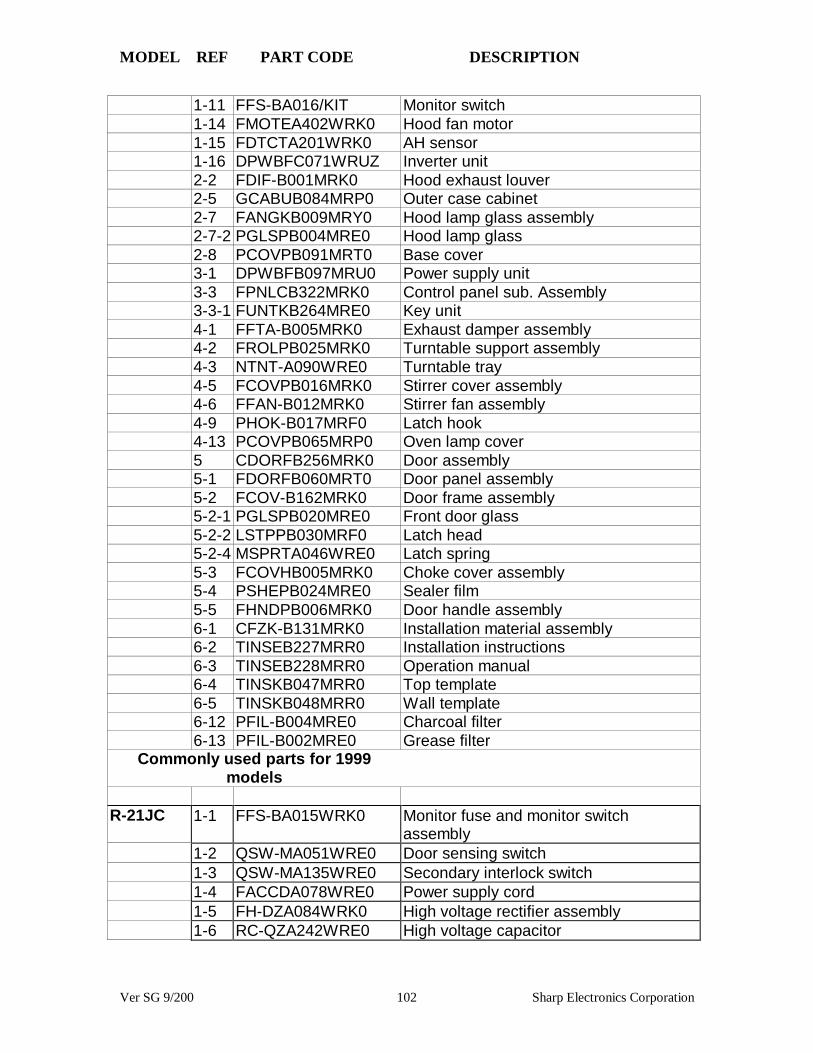
MODEL REF PART CODE DESCRIPTION
Ver SG 9/200 102 Sharp Electronics Corporation
1-11 FFS-BA016/KIT Monitor switch1-14 FMOTEA402WRK0 Hood fan motor1-15 FDTCTA201WRK0 AH sensor1-16 DPWBFC071WRUZ Inverter unit2-2 FDIF-B001MRK0 Hood exhaust louver2-5 GCABUB084MRP0 Outer case cabinet2-7 FANGKB009MRY0 Hood lamp glass assembly2-7-2 PGLSPB004MRE0 Hood lamp glass2-8 PCOVPB091MRT0 Base cover3-1 DPWBFB097MRU0 Power supply unit3-3 FPNLCB322MRK0 Control panel sub. Assembly3-3-1 FUNTKB264MRE0 Key unit4-1 FFTA-B005MRK0 Exhaust damper assembly4-2 FROLPB025MRK0 Turntable support assembly4-3 NTNT-A090WRE0 Turntable tray4-5 FCOVPB016MRK0 Stirrer cover assembly4-6 FFAN-B012MRK0 Stirrer fan assembly4-9 PHOK-B017MRF0 Latch hook4-13 PCOVPB065MRP0 Oven lamp cover5 CDORFB256MRK0 Door assembly5-1 FDORFB060MRT0 Door panel assembly5-2 FCOV-B162MRK0 Door frame assembly5-2-1 PGLSPB020MRE0 Front door glass5-2-2 LSTPPB030MRF0 Latch head5-2-4 MSPRTA046WRE0 Latch spring5-3 FCOVHB005MRK0 Choke cover assembly5-4 PSHEPB024MRE0 Sealer film5-5 FHNDPB006MRK0 Door handle assembly6-1 CFZK-B131MRK0 Installation material assembly6-2 TINSEB227MRR0 Installation instructions6-3 TINSEB228MRR0 Operation manual6-4 TINSKB047MRR0 Top template6-5 TINSKB048MRR0 Wall template6-12 PFIL-B004MRE0 Charcoal filter6-13 PFIL-B002MRE0 Grease filter
Commonly used parts for 1999models
R-21JC 1-1 FFS-BA015WRK0 Monitor fuse and monitor switchassembly
1-2 QSW-MA051WRE0 Door sensing switch1-3 QSW-MA135WRE0 Secondary interlock switch1-4 FACCDA078WRE0 Power supply cord1-5 FH-DZA084WRK0 High voltage rectifier assembly1-6 RC-QZA242WRE0 High voltage capacitor

MODEL REF PART CODE DESCRIPTION
Ver SG 9/200 103 Sharp Electronics Corporation
1-7 RMOTEA376WRE0 Fan motor1-10 RLMPTA072WRE0 Oven lamp1-11 RMOTDA233WRE0 Antenna motor1-12 RTHM-A080WRE0 Thermal cut-out 145 deg. (MAG)1-13 RTHM-A096WRE0 Thermal cut-out 125 deg. (OVEN)1-14 RTRN-A570WRE0 Power transformer1-15 RV-MZA197WRE0 Magnetron2-1 GCABUA674WRP0 Outer case cabinet3-1 CPWBFA804WRK0 Control unit assembly3-2 FPNLCB434WRK0 Panel sub assembly3-2-1 HPNLTA137WRE0 Timer sheet3-2-2 GCOVAA260WRP0 C/P case4-1 FGLSPA062WRE0 Ceramic shelf4-3 MLEVPA227WRF0 Latch switch lever A4-4 MLEVPA228WRF0 Latch switch lever B4-5 MLEVPA229WRF0 Latch switch lever C4-6 MSPRCA108WRE0 Latch lever spring4-7 MSPRTA191WRE0 Switch lever B spring4-8 PHOK-A107WRF0 Latch hook4-12 NFANJA029WRE0 Fan blade4-14 FPLT-A007WRY0 Stirrer antenna assembly5-1 FDORFA322WRT0 Door panel assembly5-2 PSHEPA649WRE0 Sealer film5-3 FANGKA206WRY0 Latch angle assembly5-4 FCOV-A002WRK0 Door case assembly5-4-3 PGLSPA516WRE0 Front door glass5-5 GWAKPA580WRM0 Door handle5-6 JHNDMA040WRW0 Handle lever5-7 LANGKA874WRW0 Latch lever5-8 LSTPPA181WRF0 Latch head5-9 MSPRTA190WRE0 Latch spring6-1 TINSEA802WRR0 Instruction book
R-25JT 1-1 FH-HZA064WRE Oven Thermistor(2)1-3 RV-MZA295WRE0 Magnetron1-4 RMOTEA391WRE0 Blower motor1-6 FACCDA084WRE0 Power supply cord1-7 FH-HZA070WRE0 Oven Thermistor(1) & Magnetron
Thermistor1-8 FW-QZA117WRK0 High voltage rectifier assembly1-9 FFS-BA015WRK0 Monitor switch and fuse 20A assembly1-10 QSW-MA020WRE0 Voltage select switch1-11 QSW-MA051WRE0 Secondary interlock switch/ Door sensing
switch1-12 RC-QZA260WRE0 High voltage capacitor
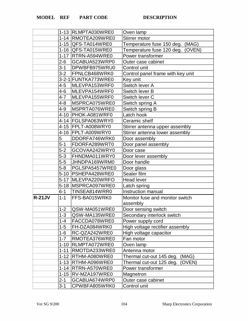
MODEL REF PART CODE DESCRIPTION
Ver SG 9/200 104 Sharp Electronics Corporation
1-13 RLMPTA030WRE0 Oven lamp1-14 RMOTEA209WRE0 Stirrer motor1-15 QFS-TA014WRE0 Temperature fuse 150 deg. (MAG)1-16 QFS-TA015WRE0 Temperature fuse 120 deg. (OVEN)1-17 RTRN-A594WRE0 Power transformer2-6 GCABUA523WRP0 Outer case cabinet3-1 DPWBFB975WRU0 Control unit3-2 FPNLCB468WRK0 Control panel frame with key unit3-2-1 FUNTKA773WRE0 Key unit4-5 MLEVPA153WRF0 Switch lever A4-6 MLEVPA154WRF0 Switch lever B4-7 MLEVPA155WRF0 Switch lever C4-8 MSPRCA075WRE0 Switch spring A4-9 MSPRTA076WRE0 Switch spring B4-10 PHOK-A081WRF0 Latch hook4-14 FGLSPA063WRY0 Ceramic shelf4-15 FPLT-A008WRY0 Stirrer antenna upper assembly4-16 FPLT-A009WRY0 Stirrer antenna lower assembly5 DDORFA746WRK0 Door assembly5-1 FDORFA289WRT0 Door panel assembly5-2 GCOVAA242WRY0 Door case5-3 FHNDMA011WRY0 Door lever assembly5-5 JHNDPA169WRM0 Door handle5-8 PGLSPA5457WRE0 Door glass5-10 PSHEPA428WRE0 Sealer film5-17 MLEVPA220WRFO Head lever5-18 MSPRCA097WRE0 Latch spring6-1 TINSEA814WRR0 Instruction manual
R-21JV 1-1 FFS-BA015WRK0 Monitor fuse and monitor switchassembly
1-2 QSW-MA051WRE0 Door sensing switch1-3 QSW-MA135WRE0 Secondary interlock switch1-4 FACCDA078WRE0 Power supply cord1-5 FH-DZA084WRK0 High voltage rectifier assembly1-6 RC-QZA242WRE0 High voltage capacitor1-7 RMOTEA376WRE0 Fan motor1-10 RLMPTA072WRE0 Oven lamp1-11 RMOTDA233WRE0 Antenna motor1-12 RTHM-A080WRE0 Thermal cut-out 145 deg. (MAG)1-13 RTHM-A096WRE0 Thermal cut-out 125 deg. (OVEN)1-14 RTRN-A570WRE0 Power transformer1-15 RV-MZA197WRE0 Magnetron2-1 GCABUA674WRP0 Outer case cabinet3-1 CPWBFA805WRK0 Control unit

MODEL REF PART CODE DESCRIPTION
Ver SG 9/200 105 Sharp Electronics Corporation
3-2 FPNLCB435WRK0 Control panel frame with key unit3-2-1 FUNTKA881WRE0 Key unit3-2-2 GCOVAA264WRP0 C/P case4-1 FGLSPA062WRE0 Ceramic shelf4-3 MLEVPA227WRF0 Latch switch lever A4-4 MLEVPA228WRF0 Latch switch lever B4-5 MLEVPA229WRF0 Latch switch lever C4-6 MSPRCA108WRE0 Latch lever spring4-7 MSPRTA191WRE0 Switch lever B spring4-8 PHOK-A107WRF0 Latch hook4-12 NFANJA029WRE0 Fan blade4-14 FPLT-A007WRY0 Stirrer antenna assembly5-1 FDORFA322WRT0 Door panel assembly5-2 PSHEPA649WRE0 Sealer film5-3 FANGKA206WRY0 Latch angle assembly5-4 FCOV-A002WRK0 Door case assembly5-4-3 PGLSPA516WRE0 Front door glass5-5 GWAKPA580WRM0 Door handle5-6 JHNDMA040WRW0 Handle lever5-7 LANGKA874WRW0 Latch lever5-8 LSTPPA181WRF0 Latch head5-9 MSPRTA190WRE0 Latch spring6-1 TINSEA802WRR0 Instruction book
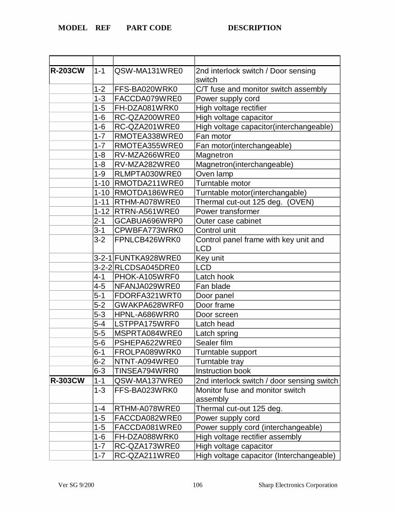
MODEL REF PART CODE DESCRIPTION
Ver SG 9/200 106 Sharp Electronics Corporation
R-203CW 1-1 QSW-MA131WRE0 2nd interlock switch / Door sensingswitch
1-2 FFS-BA020WRK0 C/T fuse and monitor switch assembly1-3 FACCDA079WRE0 Power supply cord1-5 FH-DZA081WRK0 High voltage rectifier1-6 RC-QZA200WRE0 High voltage capacitor1-6 RC-QZA201WRE0 High voltage capacitor(interchangeable)1-7 RMOTEA338WRE0 Fan motor1-7 RMOTEA355WRE0 Fan motor(interchangeable)1-8 RV-MZA266WRE0 Magnetron1-8 RV-MZA282WRE0 Magnetron(interchangeable)1-9 RLMPTA030WRE0 Oven lamp1-10 RMOTDA211WRE0 Turntable motor1-10 RMOTDA186WRE0 Turntable motor(interchangable)1-11 RTHM-A078WRE0 Thermal cut-out 125 deg. (OVEN)1-12 RTRN-A561WRE0 Power transformer2-1 GCABUA696WRP0 Outer case cabinet3-1 CPWBFA773WRK0 Control unit3-2 FPNLCB426WRK0 Control panel frame with key unit and
LCD3-2-1 FUNTKA928WRE0 Key unit3-2-2 RLCDSA045DRE0 LCD4-1 PHOK-A105WRF0 Latch hook4-5 NFANJA029WRE0 Fan blade5-1 FDORFA321WRT0 Door panel5-2 GWAKPA628WRF0 Door frame5-3 HPNL-A686WRR0 Door screen5-4 LSTPPA175WRF0 Latch head5-5 MSPRTA084WRE0 Latch spring5-6 PSHEPA622WRE0 Sealer film6-1 FROLPA089WRK0 Turntable support6-2 NTNT-A094WRE0 Turntable tray6-3 TINSEA794WRR0 Instruction book
R-303CW 1-1 QSW-MA137WRE0 2nd interlock switch / door sensing switch1-3 FFS-BA023WRK0 Monitor fuse and monitor switch
assembly1-4 RTHM-A078WRE0 Thermal cut-out 125 deg.1-5 FACCDA082WRE0 Power supply cord1-5 FACCDA081WRE0 Power supply cord (interchangeable)1-6 FH-DZA088WRK0 High voltage rectifier assembly1-7 RC-QZA173WRE0 High voltage capacitor1-7 RC-QZA211WRE0 High voltage capacitor (Interchangeable)

MODEL REF PART CODE DESCRIPTION
Ver SG 9/200 107 Sharp Electronics Corporation
1-8 RV-MZA288WRE0 Magnetron1-9 RMOTEA383WRE0 Fan motor1-11 RLMPTA068WRE0 Oven lamp1-12 RMOTDA161WRE0 Turntable motor1-12 RMOTDA211WRE0 Turntable motor(Interchangeable)1-13 RTHM-A080WRE0 Thermal cut-out 145 deg.1-14 RTRN-A576WRE0 Power transformer2-1 GCABUA690WRP0 Outer case cabinet3-1 CPWBFA821WRK0 Power unit3-2 DPWBFB914WRK0 CPU Unit3-3 FPNLCB437WRK0 Control panel frame w/key unit3-3-1 FUNTKA935WRE0 Key unit3-4 JBTN-B099WRF0 Open button3-5 MSPRCA050WRE0 Open button spring4-3 PHOK-A114WRF0 Latch hook4-5 NFANJA029WRE0 Fan blade4-11 MLEVPA233WRF0 Switch lever4-14 PCOVPA349WRE0 Waveguide cover5-1 FDORFA332WRT0 Door panel5-2 PSHEPA382WRE0 Sealer film5-3 GWAKPA610WRR0 Door frame5-4 HPNL-A716WRR0 Door screen5-5 LSTPPA188WRF0 Latch head5-6 MSPRTA187WRE0 Latch spring6-1 FROLPA079WRK0 Turntable support6-2 NTNT-A079WRE0 Turntable tray6-8 TINSEA807WRR0 Instruction book
R-305CW 1-1 QSW-MA137WRE0 2nd interlock switch / door sensing switch1-3 FFS-BA023WRK0 Monitor fuse and monitor switch
assembly1-4 RTHM-A078WRE0 Thermal cut-out 125 deg.1-5 FACCDA081WRE0 Power supply cord1-5 FACCDA082WRE0 Power supply cord (interchangeable)1-6 FH-DZA088WRK0 High voltage rectifier assembly1-7 RC-QZA173WRE0 High voltage capacitor1-7 RC-QZA211WRE0 High voltage capacitor (Interchangeable)1-8 RV-MZA288WRE0 Magnetron1-9 RMOTEA383WRE0 Fan motor1-11 RLMPTA068WRE0 Oven lamp1-11 RLMPTA030WRE0 Oven lamp(Interchangeable)1-12 RMOTDA161WRE0 Turntable motor1-12 RMOTDA211WRE0 Turntable motor(Interchangeable)1-13 RTHM-A080WRE0 Thermal cut-out 145 deg.1-14 RTRN-A580WRE0 Power transformer

MODEL REF PART CODE DESCRIPTION
Ver SG 9/200 108 Sharp Electronics Corporation
2-1 GCABUA690WRP0 Outer case cabinet3-1 CPWBFA821WRK0 Power unit3-2 DPWBFB914WRK0 CPU Unit3-3 FPNLCB429WRK0 Control panel frame w/key unit3-3-1 FUNTKA929WRE0 Key unit3-4 JBTN-B099WRF0 Open button3-5 MSPRCA050WRE0 Open button spring4-3 PHOK-A114WRF0 Latch hook4-5 NFANJA029WRE0 Fan blade4-11 MLEVPA233WRF0 Switch lever4-14 PCOVPA349WRE0 Waveguide cover5-1 FDORFA332WRT0 Door panel5-2 PSHEPA382WRE0 Sealer film5-3 GWAKPA610WRR0 Door frame5-4 HPNL-A716WRR0 Door screen5-5 LSTPPA188WRF0 Latch head5-6 MSPRTA187WRE0 Latch spring6-1 FROLPA079WRK0 Turntable support6-2 NTNT-A079WRE0 Turntable tray6-2 NTNT-A084WRE0 Turntable tray(Interchangeable)6-8 TINSEA791WRR0 Instruction book
R-308CWR-
310CW/CK
1-1 QSW-MA137WRE0 2nd interlock switch / door sensing switch
1-3 FFS-BA023WRK0 Monitor fuse and monitor switchassembly
1-4 RTHM-A078WRE0 Thermal cut-out 125 deg.1-5 FACCDA081WRE0 Power supply cord1-5 FACCDA082WRE0 Power supply cord (interchangeable)1-6 FH-DZA088WRK0 High voltage rectifier assembly1-7 RC-QZA173WRE0 High voltage capacitor1-7 RC-QZA211WRE0 High voltage capacitor (Interchangeable)1-8 RV-MZA288WRE0 Magnetron1-8 RV-MZA279WRE0 Magnetron(Interchangeable)1-9 RMOTEA383WRE0 Fan motor1-11 RLMPTA068WRE0 Oven lamp1-11 RLMPTA030WRE0 Oven lamp(Interchangeable)1-12 RMOTDA161WRE0 Turntable motor1-12 RMOTDA211WRE0 Turntable motor(Interchangeable)1-13 RTHM-A080WRE0 Thermal cut-out 145 deg.1-14 RTRN-A576WRE0 Power transformer2-1 GCABUA687WRP0 Outer case cabinet [R-310CK]2-1 GCABUA690WRP0 Outer case cabinet [R-308CW / 310CW]3-1 CPWBFA821WRK0 Power unit

MODEL REF PART CODE DESCRIPTION
Ver SG 9/200 109 Sharp Electronics Corporation
3-2 DPWBFB914WRK0 CPU Unit3-3 FPNLCB414WRK0 Control panel frame w/key unit [R-310CK]3-3 FPNLCB416WRK0 Control panel frame w/key unit [R-
310CW]3-3 FPNLCB421WRK0 Control panel frame w/key unit [R-
308CW]3-3-1 FUNTKA915WRE0 Key unit [R-310CK]3-3-1 FUNTKA917WRE0 Key unit [R-310CW]3-3-1 FUNTKA922WRE0 Key unit [R-308CW]3-4 JBTN-B097WRF0 Open button [R-310CK]3-4 JBTN-B099WRF0 Open button [R-308CW / 310CW]3-5 MSPRCA050WRE0 Open button spring4-3 PHOK-A114WRF0 Latch hook4-5 NFANJA029WRE0 Fan blade4-11 MLEVPA233WRF0 Switch lever4-14 PCOVPA349WRE0 Waveguide cover5-1 FDORFA332WRT0 Door panel5-2 PSHEPA382WRE0 Sealer film5-3 GWAKPA606WRR0 Door frame [R-310CK]5-3 GWAKPA610WRR0 Door frame [R-310CW / 308CW]5-4 HPNL-A714WRR0 Door screen [R-310CK]5-4 HPNL-A716WRR0 Door screen [R-310CW / 308CW]5-5 LSTPPA188WRF0 Latch head5-6 MSPRTA187WRE0 Latch spring6-1 FROLPA079WRK0 Turntable support6-2 NTNT-A079WRE0 Turntable tray6-2 NTNT-A084WRE0 Turntable tray(Interchangeable)6-8 TINSEA791WRR0 Instruction book
R320BG 1-1 QSW-MA131WRE0 2nd interlock switch / Door sensingswitch
1-1 QSW-MA110WRE0 Secondary interlock switch / Doorsensing switch(interchangeable)
1-3 FFS-BA021WRK0 Monitor fuse and monitor switchassembly
1-4 RTHM-A078WRE0 Thermal cut-out 125 deg. (OVEN)1-5 FACCDA077WRE0 Power supply cord1-6 FH-DZA083WRK0 High voltage rectifier assembly1-7 RC-QZA236WRE0 High voltage capacitor1-8 RV-MZA267WRE0 Magnetron1-9 RMOTEA355WRE0 Fan motor1-11 RLMPTA068WRE0 Oven lamp1-12 RMOTDA161WRE0 Turntable motor1-13 RTHM-A048WRE0 Thermal cut-out 170 deg. (MAG)1-14 RTRN-A569WRE0 Power transformer

MODEL REF PART CODE DESCRIPTION
Ver SG 9/200 110 Sharp Electronics Corporation
2-1 GCABUA693WRP0 Outer case cabinet3-1 CPWBFA776WRK0 Power unit3-2 DPWBFB753WRK0 CPU Unit3-3 FPNLCB415WRK0 Control panel frame with key unit3-3-1 FUNTKA916WRE0 Key unit3-3-2 JBTN-B098WRF0 Open button3-3-3 MSPRCA050WRE0 Open button spring4-3 PHOK-A106WRF0 Latch hook4-5 NFANJA029WRE0 Fan blade5-1 FDORFA318WRT0 Door panel5-2 PSHEPA382WRE0 Sealer film5-3 GWAKPA608WRR0 Door frame5-4 HPNL-A684WRR0 Door screen5-5 LSTPPA139WRF0 Latch head5-6 MSPRTA187WRE0 Latch spring6-1 FROLPA079WRK0 Turntable support6-2 NTNT-A084WRE0 Turntable tray6-8 TINSEA777WRR0 Instruction book
R320CD/CK/CW
1-1 QSW-MA137WRE0 2nd interlock switch / Door sensingswitch
R330CK/CW
1-3 FFS-BA023WRK0 Monitor fuse and monitor switchassembly
1-4 RTHM-A078WRE0 Thermal cut-out 125 deg.1-5 FACCDA081WRE0 Power supply cord1-5 FACCDA082WRE0 Power supply cord (Interchangable)1-6 FH-DZA088WRK0 High voltage rectifier assembly1-7 RC-QZA173WRE0 High voltage capacitor1-7 RC-QZA211WRE0 High voltage capacitor(Interchangable)1-8 RV-MZA288WRE0 Magnetron1-8 RV-MZA279WRE0 Magnetron(Interchangable)1-9 RMOTEA383WRE0 Fan motor1-11 RLMPTA068WRE0 Oven lamp1-11 RLMPTA030WRE0 Oven lamp(Interchangable)1-12 RMOTDA161WRE0 Turntable motor1-12 RMOTDA211WRE0 Turntable motor(Interchangable1-13 RTHM-A080WRE0 Thermal cut-out 145 deg.1-14 RTRN-A576WRE0 Power transformer2-1 GCABUA702WRP0 Outer case cabinet(R320CD)2-1 GCABUA687WRP0 Outer case cabinet(R320CK / R330CK)2-1 GCABUA690WRP0 Outer case cabinet(R320CW / R330CW)3-1 CPWBFA775WRK0 Power unit3-2 DPWBFB917WRK0 CPU Unit(R320CD /CK / CW)3-2 DPWBFB918WRK0 CPU Unit(R330CK / CW)3-3 FPNLCB422WRK0 Control panel frame with key
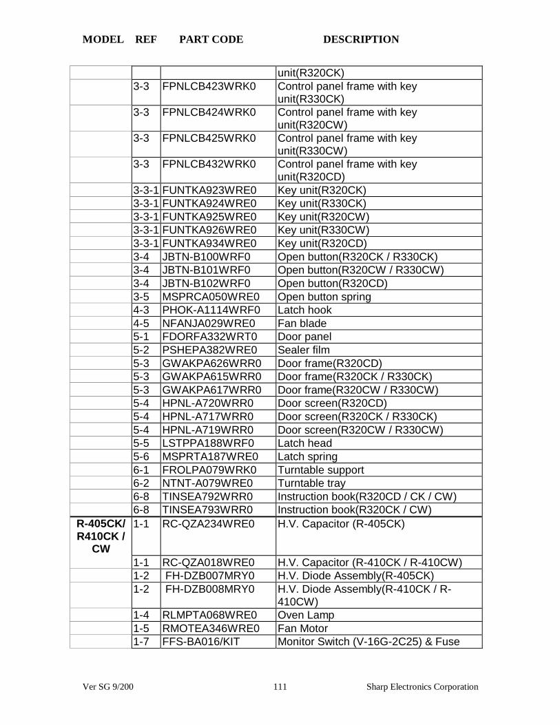
MODEL REF PART CODE DESCRIPTION
Ver SG 9/200 111 Sharp Electronics Corporation
unit(R320CK)3-3 FPNLCB423WRK0 Control panel frame with key
unit(R330CK)3-3 FPNLCB424WRK0 Control panel frame with key
unit(R320CW)3-3 FPNLCB425WRK0 Control panel frame with key
unit(R330CW)3-3 FPNLCB432WRK0 Control panel frame with key
unit(R320CD)3-3-1 FUNTKA923WRE0 Key unit(R320CK)3-3-1 FUNTKA924WRE0 Key unit(R330CK)3-3-1 FUNTKA925WRE0 Key unit(R320CW)3-3-1 FUNTKA926WRE0 Key unit(R330CW)3-3-1 FUNTKA934WRE0 Key unit(R320CD)3-4 JBTN-B100WRF0 Open button(R320CK / R330CK)3-4 JBTN-B101WRF0 Open button(R320CW / R330CW)3-4 JBTN-B102WRF0 Open button(R320CD)3-5 MSPRCA050WRE0 Open button spring4-3 PHOK-A1114WRF0 Latch hook4-5 NFANJA029WRE0 Fan blade5-1 FDORFA332WRT0 Door panel5-2 PSHEPA382WRE0 Sealer film5-3 GWAKPA626WRR0 Door frame(R320CD)5-3 GWAKPA615WRR0 Door frame(R320CK / R330CK)5-3 GWAKPA617WRR0 Door frame(R320CW / R330CW)5-4 HPNL-A720WRR0 Door screen(R320CD)5-4 HPNL-A717WRR0 Door screen(R320CK / R330CK)5-4 HPNL-A719WRR0 Door screen(R320CW / R330CW)5-5 LSTPPA188WRF0 Latch head5-6 MSPRTA187WRE0 Latch spring6-1 FROLPA079WRK0 Turntable support6-2 NTNT-A079WRE0 Turntable tray6-8 TINSEA792WRR0 Instruction book(R320CD / CK / CW)6-8 TINSEA793WRR0 Instruction book(R320CK / CW)
R-405CK/R410CK /
CW
1-1 RC-QZA234WRE0 H.V. Capacitor (R-405CK)
1-1 RC-QZA018WRE0 H.V. Capacitor (R-410CK / R-410CW)1-2 FH-DZB007MRY0 H.V. Diode Assembly(R-405CK)1-2 FH-DZB008MRY0 H.V. Diode Assembly(R-410CK / R-
410CW)1-4 RLMPTA068WRE0 Oven Lamp1-5 RMOTEA346WRE0 Fan Motor1-7 FFS-BA016/KIT Monitor Switch (V-16G-2C25) & Fuse
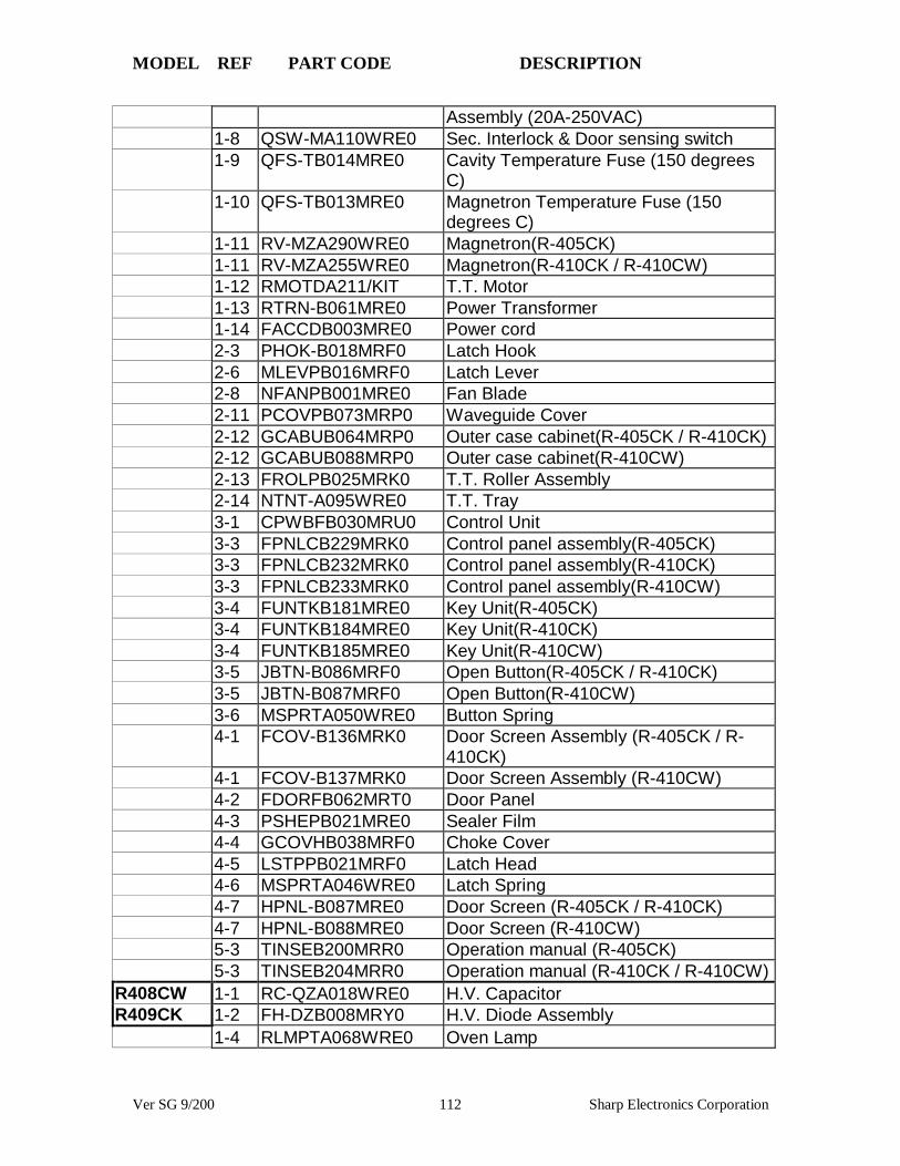
MODEL REF PART CODE DESCRIPTION
Ver SG 9/200 112 Sharp Electronics Corporation
Assembly (20A-250VAC)1-8 QSW-MA110WRE0 Sec. Interlock & Door sensing switch1-9 QFS-TB014MRE0 Cavity Temperature Fuse (150 degrees
C)1-10 QFS-TB013MRE0 Magnetron Temperature Fuse (150
degrees C)1-11 RV-MZA290WRE0 Magnetron(R-405CK)1-11 RV-MZA255WRE0 Magnetron(R-410CK / R-410CW)1-12 RMOTDA211/KIT T.T. Motor1-13 RTRN-B061MRE0 Power Transformer1-14 FACCDB003MRE0 Power cord2-3 PHOK-B018MRF0 Latch Hook2-6 MLEVPB016MRF0 Latch Lever2-8 NFANPB001MRE0 Fan Blade2-11 PCOVPB073MRP0 Waveguide Cover2-12 GCABUB064MRP0 Outer case cabinet(R-405CK / R-410CK)2-12 GCABUB088MRP0 Outer case cabinet(R-410CW)2-13 FROLPB025MRK0 T.T. Roller Assembly2-14 NTNT-A095WRE0 T.T. Tray3-1 CPWBFB030MRU0 Control Unit3-3 FPNLCB229MRK0 Control panel assembly(R-405CK)3-3 FPNLCB232MRK0 Control panel assembly(R-410CK)3-3 FPNLCB233MRK0 Control panel assembly(R-410CW)3-4 FUNTKB181MRE0 Key Unit(R-405CK)3-4 FUNTKB184MRE0 Key Unit(R-410CK)3-4 FUNTKB185MRE0 Key Unit(R-410CW)3-5 JBTN-B086MRF0 Open Button(R-405CK / R-410CK)3-5 JBTN-B087MRF0 Open Button(R-410CW)3-6 MSPRTA050WRE0 Button Spring4-1 FCOV-B136MRK0 Door Screen Assembly (R-405CK / R-
410CK)4-1 FCOV-B137MRK0 Door Screen Assembly (R-410CW)4-2 FDORFB062MRT0 Door Panel4-3 PSHEPB021MRE0 Sealer Film4-4 GCOVHB038MRF0 Choke Cover4-5 LSTPPB021MRF0 Latch Head4-6 MSPRTA046WRE0 Latch Spring4-7 HPNL-B087MRE0 Door Screen (R-405CK / R-410CK)4-7 HPNL-B088MRE0 Door Screen (R-410CW)5-3 TINSEB200MRR0 Operation manual (R-405CK)5-3 TINSEB204MRR0 Operation manual (R-410CK / R-410CW)
R408CW 1-1 RC-QZA018WRE0 H.V. CapacitorR409CK 1-2 FH-DZB008MRY0 H.V. Diode Assembly
1-4 RLMPTA068WRE0 Oven Lamp

MODEL REF PART CODE DESCRIPTION
Ver SG 9/200 113 Sharp Electronics Corporation
1-5 RMOTEA346WRE0 Fan Motor1-7 FFS-BA016/KIT Monitor Switch (V-16G-2C25) & Fuse
Assembly (20A-250VAC)1-8 QSW-MA110WRE0 Sec. Interlock & Door sensing switch1-9 QFS-TB014MRE0 Cavity Temperature Fuse (150 degrees
C)1-10 QFS-TB013MRE0 Magnetron Temperature Fuse (150
degrees C)1-11 RV-MZA290WRE0 Magnetron1-12 RMOTDA211/KIT T.T. Motor1-13 RTRN-B061MRE0 Power Transformer1-14 FACCDB003MRE0 Power cord2-3 PHOK-B018MRF0 Latch Hook2-6 MLEVPB016MRF0 Latch Lever2-8 NFANPB001MRE0 Fan Blade2-11 PCOVPB073MRP0 Waveguide Cover2-12 GCABUB064MRP0 Outer case cabinet(R-409CK )2-12 GCABUB088MRP0 Outer case cabinet(R-408CW)2-13 FROLPB025MRK0 T.T. Roller Assembly2-14 NTNT-A095WRE0 T.T. Tray3-1 CPWBFB030MRU0 Control Unit3-3 FPNLCB230MRK0 Control panel assembly(R-408CW)3-3 FPNLCB231MRK0 Control panel assembly(R-409CK)3-4 FUNTKB182MRE0 Key Unit(R-408CW)3-4 FUNTKB183MRE0 Key Unit(R-409CK)3-5 JBTN-B087MRF0 Open Button(R-408CW)3-5 JBTN-B086MRF0 Open Button(R-409CK)3-6 MSPRTA050WRE0 Button Spring4-1 FCOV-B136MRK0 Door Screen Assembly (R-409CK )4-1 FCOV-B137MRK0 Door Screen Assembly (R-408CW)4-2 FDORFB062MRT0 Door Panel4-3 PSHEPB021MRE0 Sealer Film4-4 GCOVHB038MRF0 Choke Cover4-5 LSTPPB021MRF0 Latch Head4-6 MSPRTA046WRE0 Latch Spring4-7 HPNL-B087MRE0 Door Screen (R-409CK)4-7 HPNL-B088MRE0 Door Screen (R-408CW)5-3 TINSEB204MRR0 Operation manual
R420CK 1-1 RC-QZA018WRE0 H.V. CapacitorR420CW 1-2 FH-DZB008MRY0 H.V. Diode Assembly
1-4 RLMPTA068WRE0 Oven Lamp1-5 RMOTEA346WRE0 Fan Motor1-7 FFS-BA016/KIT Monitor Switch (V-16G-2C25) & Fuse
Assembly (20A-250VAC)

MODEL REF PART CODE DESCRIPTION
Ver SG 9/200 114 Sharp Electronics Corporation
1-8 QSW-MA085WRE0 Sec. Interlock & Door sensing switch1-9 QFS-TB013MRE0 Magnetron Temperature Fuse (150
degrees C)1-10 QFS-TB014MRE0 Cavity Temperature Fuse (150 degrees
C)1-11 RV-MZA255WRE0 Magnetron1-12 RMOTDA211/KIT T.T. Motor1-13 RTRN-B061MRE0 Power Transformer1-14 FACCDB003MRE0 Power cord2-3 GCABUB064MRP0 Outer case cabinet(R-420CK )2-3 GCABUB088MRP0 Outer case cabinet(R-420CW)3-1 CPWBFB031MRU0 Control Unit3-2 FPNLCB241MRK0 Control panel frame w/key unit(R-420CK)3-2 FPNLCB242MRK0 Control panel frame(R-420CW)3-2-1 FUNTKB193MRE0 Key Unit(R-420CK)3-2-1 FUNTKB194MRE0 Key Unit(R-420CW)3-2-2 JBTN-B087MRF0 Open Button(R-420CW)3-2-2 JBTN-B086MRF0 Open Button(R-420CK)3-2-3 MSPRTA050WRE0 Open Button Spring4-3 PHOK-B018MRF0 Latch Hook4-4 MLEVPB016MRF0 Switch Lever4-6 NFANPB001MRE0 Fan Blade4-9 PCOVPB073MRP0 Waveguide Cover5-1 FCOV-B136MRK0 Door Frame Assembly (R-420CK )5-1 FCOV-B137MRK0 Door Screen Assembly (R-420CW)5-1-1 LSTPPB021MRF0 Latch Head5-1-2 MSPRTA046WRE0 Latch Spring5-2 FDORFB062MRT0 Door Panel5-3 PSHEPB021MRE0 Sealer Film5-4 GCOVHB038MRF0 Choke Cover5-5 HPNL-B087MRE0 Door Screen (R-420CK)5-5 HPNL-B088MRE0 Door Screen (R-420CW)6-4 FROLPB025MRK0 T.T. Support6-5 NTNT-A095WRE0 T.T. Tray6-8 TINSEB205MRR0 Operation manual
R430CS 1-1 RC-QZA018WRE0 H.V. Capacitor1-2 FH-DZB008MRY0 H.V. Diode Assembly1-4 RLMPTA068WRE0 Oven Lamp1-5 RMOTEA346WRE0 Fan Motor1-7 FFS-BA016/KIT Monitor Switch (V-16G-2C25) & Fuse
Assembly (20A-250VAC)1-8 QSW-MA085WRE0 Sec. Interlock & Door sensing switch1-9 QFS-TB013MRE0 Magnetron Temperature Fuse (150
degrees C)
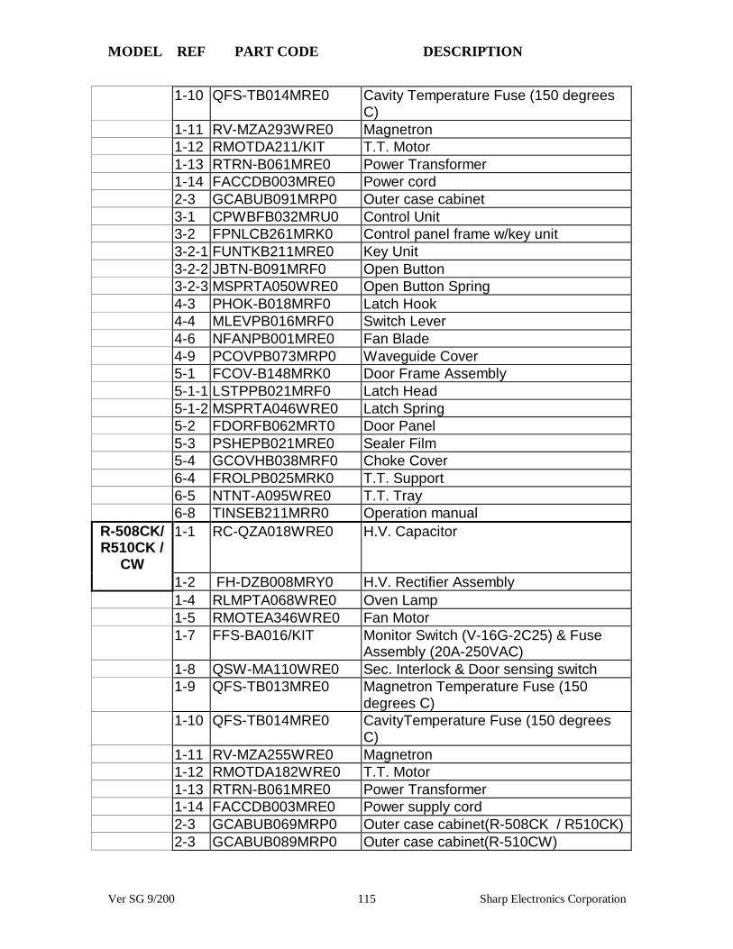
MODEL REF PART CODE DESCRIPTION
Ver SG 9/200 115 Sharp Electronics Corporation
1-10 QFS-TB014MRE0 Cavity Temperature Fuse (150 degreesC)
1-11 RV-MZA293WRE0 Magnetron1-12 RMOTDA211/KIT T.T. Motor1-13 RTRN-B061MRE0 Power Transformer1-14 FACCDB003MRE0 Power cord2-3 GCABUB091MRP0 Outer case cabinet3-1 CPWBFB032MRU0 Control Unit3-2 FPNLCB261MRK0 Control panel frame w/key unit3-2-1 FUNTKB211MRE0 Key Unit3-2-2 JBTN-B091MRF0 Open Button3-2-3 MSPRTA050WRE0 Open Button Spring4-3 PHOK-B018MRF0 Latch Hook4-4 MLEVPB016MRF0 Switch Lever4-6 NFANPB001MRE0 Fan Blade4-9 PCOVPB073MRP0 Waveguide Cover5-1 FCOV-B148MRK0 Door Frame Assembly5-1-1 LSTPPB021MRF0 Latch Head5-1-2 MSPRTA046WRE0 Latch Spring5-2 FDORFB062MRT0 Door Panel5-3 PSHEPB021MRE0 Sealer Film5-4 GCOVHB038MRF0 Choke Cover6-4 FROLPB025MRK0 T.T. Support6-5 NTNT-A095WRE0 T.T. Tray6-8 TINSEB211MRR0 Operation manual
R-508CK/R510CK /
CW
1-1 RC-QZA018WRE0 H.V. Capacitor
1-2 FH-DZB008MRY0 H.V. Rectifier Assembly1-4 RLMPTA068WRE0 Oven Lamp1-5 RMOTEA346WRE0 Fan Motor1-7 FFS-BA016/KIT Monitor Switch (V-16G-2C25) & Fuse
Assembly (20A-250VAC)1-8 QSW-MA110WRE0 Sec. Interlock & Door sensing switch1-9 QFS-TB013MRE0 Magnetron Temperature Fuse (150
degrees C)1-10 QFS-TB014MRE0 CavityTemperature Fuse (150 degrees
C)1-11 RV-MZA255WRE0 Magnetron1-12 RMOTDA182WRE0 T.T. Motor1-13 RTRN-B061MRE0 Power Transformer1-14 FACCDB003MRE0 Power supply cord2-3 GCABUB069MRP0 Outer case cabinet(R-508CK / R510CK)2-3 GCABUB089MRP0 Outer case cabinet(R-510CW)
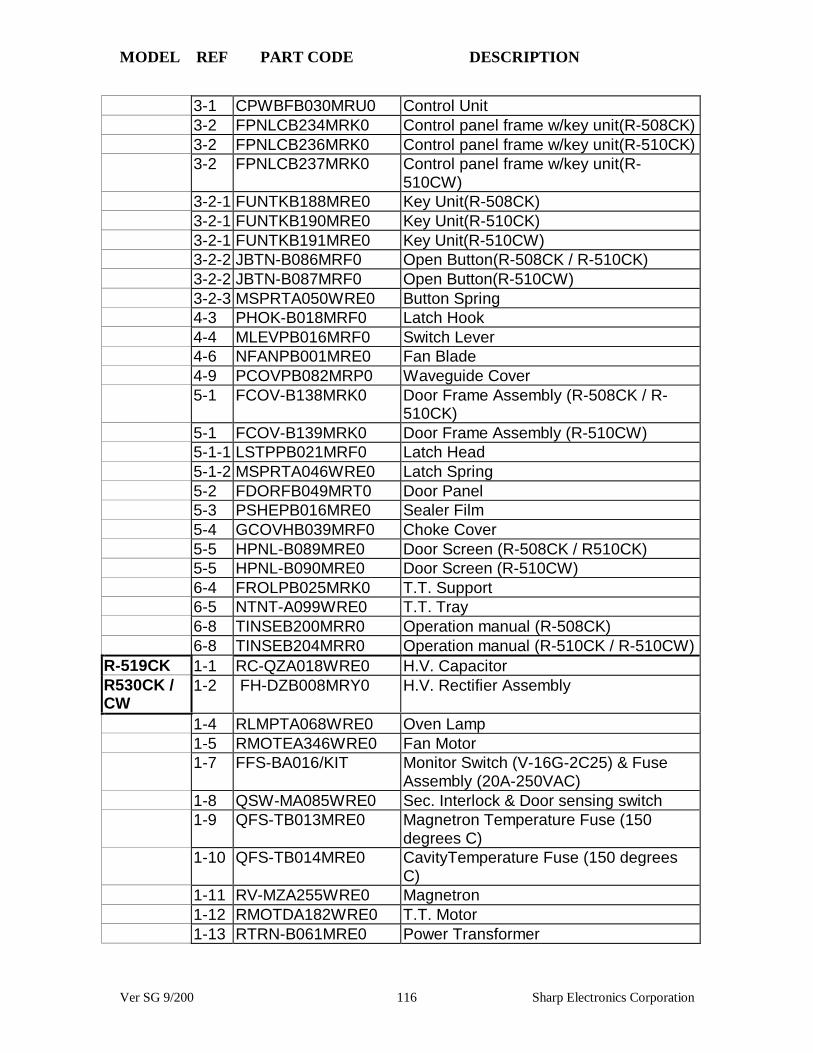
MODEL REF PART CODE DESCRIPTION
Ver SG 9/200 116 Sharp Electronics Corporation
3-1 CPWBFB030MRU0 Control Unit3-2 FPNLCB234MRK0 Control panel frame w/key unit(R-508CK)3-2 FPNLCB236MRK0 Control panel frame w/key unit(R-510CK)3-2 FPNLCB237MRK0 Control panel frame w/key unit(R-
510CW)3-2-1 FUNTKB188MRE0 Key Unit(R-508CK)3-2-1 FUNTKB190MRE0 Key Unit(R-510CK)3-2-1 FUNTKB191MRE0 Key Unit(R-510CW)3-2-2 JBTN-B086MRF0 Open Button(R-508CK / R-510CK)3-2-2 JBTN-B087MRF0 Open Button(R-510CW)3-2-3 MSPRTA050WRE0 Button Spring4-3 PHOK-B018MRF0 Latch Hook4-4 MLEVPB016MRF0 Switch Lever4-6 NFANPB001MRE0 Fan Blade4-9 PCOVPB082MRP0 Waveguide Cover5-1 FCOV-B138MRK0 Door Frame Assembly (R-508CK / R-
510CK)5-1 FCOV-B139MRK0 Door Frame Assembly (R-510CW)5-1-1 LSTPPB021MRF0 Latch Head5-1-2 MSPRTA046WRE0 Latch Spring5-2 FDORFB049MRT0 Door Panel5-3 PSHEPB016MRE0 Sealer Film5-4 GCOVHB039MRF0 Choke Cover5-5 HPNL-B089MRE0 Door Screen (R-508CK / R510CK)5-5 HPNL-B090MRE0 Door Screen (R-510CW)6-4 FROLPB025MRK0 T.T. Support6-5 NTNT-A099WRE0 T.T. Tray6-8 TINSEB200MRR0 Operation manual (R-508CK)6-8 TINSEB204MRR0 Operation manual (R-510CK / R-510CW)
R-519CK 1-1 RC-QZA018WRE0 H.V. CapacitorR530CK /CW
1-2 FH-DZB008MRY0 H.V. Rectifier Assembly
1-4 RLMPTA068WRE0 Oven Lamp1-5 RMOTEA346WRE0 Fan Motor1-7 FFS-BA016/KIT Monitor Switch (V-16G-2C25) & Fuse
Assembly (20A-250VAC)1-8 QSW-MA085WRE0 Sec. Interlock & Door sensing switch1-9 QFS-TB013MRE0 Magnetron Temperature Fuse (150
degrees C)1-10 QFS-TB014MRE0 CavityTemperature Fuse (150 degrees
C)1-11 RV-MZA255WRE0 Magnetron1-12 RMOTDA182WRE0 T.T. Motor1-13 RTRN-B061MRE0 Power Transformer

MODEL REF PART CODE DESCRIPTION
Ver SG 9/200 117 Sharp Electronics Corporation
1-14 FACCDB003MRE0 Power supply cord2-3 GCABUB069MRP0 Outer case cabinet(R-519CK)2-3 GCABUB083MRP0 Outer case cabinet(R-530CK)2-3 GCABUB089MRP0 Outer case cabinet(R-530CW)3-1 CPWBFB031MRU0 Control Unit(R-519CK)3-1 CPWBFB032MRU0 Control Unit(R-530CK / CW)3-2 FPNLCB249MRK0 Control panel frame w/key unit(R-530CK)3-2 FPNLCB250MRK0 Control panel frame w/key unit(R-
530CW)3-2 FPNLCB262MRK0 Control panel frame w/key unit(R-519CK)3-2-1 FUNTKB199MRE0 Key Unit(R-530CK)3-2-1 FUNTKB200MRE0 Key Unit(R-530CW)3-2-1 FUNTKB212MRE0 Key Unit(R-519CK)3-2-2 JBTN-B086MRF0 Open Button(R-519CK/ R530CK)3-2-2 JBTN-B087MRF0 Open Button(R-530CW)3-2-3 MSPRTA050WRE0 Open Button Spring4-3 PHOK-B018MRF0 Latch Hook4-4 MLEVPB016MRF0 Switch Lever4-6 NFANPB001MRE0 Fan Blade4-9 PCOVPB082MRP0 Waveguide Cover5-1 FCOV-B138MRK0 Door Frame Assembly (R-519CK / R-
530CK)5-1 FCOV-B139MRK0 Door Frame Assembly (R-530CW)5-1-1 LSTPPB021MRF0 Latch Head5-1-2 MSPRTA046WRE0 Latch Spring5-2 FDORFB049MRT0 Door Panel5-3 PSHEPB016MRE0 Sealer Film5-4 GCOVHB039MRF0 Choke Cover5-5 HPNL-B089MRE0 Door Screen (R-519CK / R530CK)5-5 HPNL-B090MRE0 Door Screen (R-530CW)6-4 FROLPB025MRK0 T.T. Support6-5 NTNT-A099WRE0 T.T. Tray6-8 TINSEB205MRR0 Operation manual (R-519CK)6-8 TINSEB206MRR0 Operation manual (R-530CK / R-530CW)
R1600/01/02
1-1 FH-DZB012MRY0 High voltage rectifier
1-2 RC-QZA234WRE0 High voltage capacitor1-3 QFS-TA013WRE0 Temperature fuse 150 degrees C
(Magnetron)1-4 RMOTDA211WRE0 Turntable motor1-5 RMOTDA214WRE0 Stirrer motot1-6 RTHM-B005MRE0 Thermal cut-out N.O. 60 degrees C
(Hood fan)

MODEL REF PART CODE DESCRIPTION
Ver SG 9/200 118 Sharp Electronics Corporation
1-7 RTRN-B062MRE0 Power Transformer1-8 RV-MZA281WRE0 Magnetron1-10 QSW-MA110WRE0 Secondary interlock and door sensing
switches1-11 FFS-BA016/KIT Monitor switch with fuse assembly1-12 FACCDB011MRE0 Power supply cord1-14 FMOTEA366WRK0 Hood fan motor1-15 RMOTEA346WRE0 Fan motor1-16 RLMPTA068WRE0 Oven lamp1-17 RTHM-A070WRE0 Thermal cut-out 145 degrees C ( cavity)2-2 PDIF-B018MRF0 Hood exhaust louver(R1600)2-2 PDIF-B019MRF0 Hood exhaust louver(R1601)2-2 PDIF-B020MRF0 Hood exhaust louver(R1602)2-5 GCABUB084MRP0 Outer case cabinet(R1600)2-5 GCABUB090MRP0 Outer case cabinet(R1601)2-5 GCABUB086MRP0 Outer case cabinet(R1602)2-7 FANGKB009MRY0 Hood lamp glass assembly(R1600)2-7 FANGKB010MRY0 Hood lamp glass assembly(R1601)2-7 FANGKB011MRY0 Hood lamp glass assembly(R1602)2-7-1 LANGQB016MRP0 Hood lamp glass angle(R1600)2-7-1 LANGQB020MRP0 Hood lamp glass angle(R1601)2-7-1 LANGQB027MRP0 Hood lamp glass angle(R1602)2-7-2 PGLSPB004MRE0 Hood lamp glass3-1 DPWBFB033MRU0 Control unit3-2 FPNLCB256MRK0 Control panel sub. Assembly(R1600)3-2 FPNLCB257MRK0 Control panel sub. Assembly(R1601)3-2 FPNLCB258MRK0 Control panel sub. Assembly(R1602)3-2-1 FUNTKB206MRE0 Key Unit(R1600)3-2-1 FUNTKB207MRE0 Key Unit(R1601)3-2-1 FUNTKB208MRE0 Key Unit(R1602)4-3 NTNT-A090WRE0 Turntable tray4-5 FCOVPB016MRY0 Stirrer cover assembly4-6 FFAN-B010MRK0 Stirrer fan assembly4-9 PHOK-B017MRF0 Latch hook4-11 NFANPB001MRE0 Fan blade4-13 PCOVPB065MRP0 Oven lamp cover5-1 FDORFB060MRT0 Door panel assembly5-2 FCOV-B146MRK0 Door frame assembly(R1600)5-2 FCOV-B145MRK0 Door frame assembly(R1601)5-2 FCOV-B147MRK0 Door frame assembly(R1602)5-2-1 PGLSPB012MRE0 Front Door Glass(R1600)5-2-1 PGLSPB014MRE0 Front Door Glass(R1601)5-2-1 PGLSPB013MRE0 Front Door Glass(R1602)5-2-5 GWAKPB105MRR0 Door Frame(R1600)

MODEL REF PART CODE DESCRIPTION
Ver SG 9/200 119 Sharp Electronics Corporation
5-2-5 GWAKPB104MRR0 Door Frame(R1601)5-2-5 GWAKPB106MRR0 Door Frame(R1602)5-4 PSHEPB024MRE0 Sealer film5-5 FHNDPB002MRK0 Door handle assembly(R1600)5-5 FHNDPB001MRK0 Door handle assembly(R1601)5-5 FHNDPB003MRK0 Door handle assembly(R1602)6-1 CFZK-B131MRK0 Installation material assembly6-2 TINSEB177MRR0 Installation instruction6-3 TINSEB210MRR0 Operation manual6-12 PFIL-B004MRE0 Charcoal filter6-13 PFIL-B002MRE0 Grease filter
R1610/11/12
1-1 FH-DZB012MRY0 High voltage rectifier
1-2 RC-QZA234WRE0 High voltage capacitor1-3 QFS-TA013WRE0 Temperature fuse 150 degrees C
(Magnetron)1-4 RMOTDA211WRE0 Turntable motor1-5 RMOTDA214WRE0 Stirrer motot1-6 RTHM-B005MRE0 Thermal cut-out N.O. 60 degrees C
(Hood fan)1-7 RTRN-B062MRE0 Power Transformer1-8 RV-MZA281WRE0 Magnetron1-10 QSW-MA110WRE0 Secondary interlock and door sensing
switches1-11 FFS-BA016/KIT Monitor switch with fuse assembly1-12 FACCDB011MRE0 Power supply cord1-14 FMOTEA366WRK0 Hood fan motor1-15 RMOTEA346WRE0 Fan motor1-16 RLMPTA068WRE0 Oven lamp1-17 RTHM-A070WRE0 Thermal cut-out 145 degrees C ( cavity)1-18 FDTCTA201WRK0 AH sensor2-2 PDIF-B018MRF0 Hood exhaust louver(R1610)2-2 PDIF-B019MRF0 Hood exhaust louver(R1611)2-2 PDIF-B020MRF0 Hood exhaust louver(R1612)2-5 GCABUB084MRP0 Outer case cabinet(R1610)2-5 GCABUB090MRP0 Outer case cabinet(R1611)2-5 GCABUB086MRP0 Outer case cabinet(R1612)2-7 FANGKB009MRY0 Hood lamp glass assembly(R1610)2-7 FANGKB010MRY0 Hood lamp glass assembly(R1611)2-7 FANGKB011MRY0 Hood lamp glass assembly(R1612)2-7-1 LANGQB016MRP0 Hood lamp glass angle(R1610)2-7-1 LANGQB020MRP0 Hood lamp glass angle(R1610)2-7-1 LANGQB027MRP0 Hood lamp glass angle(R1612)2-7-2 PGLSPB004MRE0 Hood lamp glass

MODEL REF PART CODE DESCRIPTION
Ver SG 9/200 120 Sharp Electronics Corporation
3-1 DPWBFB037MRU0 Control unit3-2 FPNLCB263MRK0 Control panel sub. Assembly(R1610)3-2 FPNLCB264MRK0 Control panel sub. Assembly(R1611)3-2 FPNLCB265MRK0 Control panel sub. Assembly(R1612)3-2-1 FUNTKB213MRE0 Key Unit(R1610)3-2-1 FUNTKB214MRE0 Key Unit(R1611)3-2-1 FUNTKB215MRE0 Key Unit(R1612)4-3 NTNT-A090WRE0 Turntable tray4-5 FCOVPB016MRY0 Stirrer cover assembly4-6 FFAN-B010MRK0 Stirrer fan assembly4-9 PHOK-B017MRF0 Latch hook4-11 NFANPB001MRE0 Fan blade4-13 PCOVPB065MRP0 Oven lamp cover5-1 FDORFB060MRT0 Door panel assembly5-2 FCOV-B146MRK0 Door frame assembly(R1610)5-2 FCOV-B145MRK0 Door frame assembly(R1611)5-2 FCOV-B147MRK0 Door frame assembly(R1612)5-2-1 PGLSPB012MRE0 Front Door Glass(R1610)5-2-1 PGLSPB014MRE0 Front Door Glass(R1611)5-2-1 PGLSPB013MRE0 Front Door Glass(R1612)5-2-5 GWAKPB105MRR0 Door Frame(R1610)5-2-5 GWAKPB104MRR0 Door Frame(R1611)5-2-5 GWAKPB106MRR0 Door Frame(R1612)5-4 PSHEPB024MRE0 Sealer film5-5 FHNDPB002MRK0 Door handle assembly(R1610)5-5 FHNDPB001MRK0 Door handle assembly(R1611)5-5 FHNDPB003MRK0 Door handle assembly(R1612)6-1 CFZK-B131MRK0 Installation material assembly6-2 TINSEB177MRR0 Installation instruction6-3 TINSEB210MRR0 Operation manual6-12 PFIL-B004MRE0 Charcoal filter6-13 PFIL-B002MRE0 Grease filter
R1855A 1-1 FH-DZB010MRY0 High voltage rectifier1-2 RC-QZB011MRE0 High voltage capacitor1-3 QFS-TA013WRE0 Temperature fuse 150 degrees C1-4 RMOTDA174WRE0 Turntable motor1-6 RMOTDA214WRE0 Stirrer motot1-7 RTHM-0044MRE0 Thermal cut-out N.O 60degrees C1-8 RTRN-B063MRE0 Power Transformer1-9 RV-MZA255WRE0 Magnetron1-11 QSW-MA085WRE0 Secondary interlock and door sensing
switches1-12 FFS-BA018/KIT Monitor switch with fuse assembly1-13 FACCDB011MRE0 Power supply cord

MODEL REF PART CODE DESCRIPTION
Ver SG 9/200 121 Sharp Electronics Corporation
1-17 FMOTEA362WRK0 Hood fan motor1-18 RMOTEA343WRK0 Convection Motor1-19 RMOTEA344WRE0 Fan motor1-20 RLMPTA077WRE0 Hood Lamp and Oven lamp1-21 FDTCTA171WRK0 AH Sensor2-1 PFIL-B002MRE0 Grease filter2-2 PDIF-B011MRF0 Hood exhaust louver2-5 GCABUB065MRP0 Outer case cabinet2-7 FANGKB009MRY0 Hood lamp glass assembly2-7-1 LANGQB016MRP0 Hood lamp glass angle2-7-2 PGLSPB004MRE0 Hood lamp glass3-1 DPWBFB061MRU0 Control unit3-2 FPNLCB153MRK0 Control panel sub. Assembly3-2-1 FUNTKB108MRE0 Key Unit3-2-3 MSPRTA050WRE0 Open Button spring3-2-4 JBTN-B053MRF0 Open Button4-3 NTNT-A006MRE0 Turntable tray4-5 FCOVPB002MRY0 Stirrer cover assembly4-6 FFAN-B008MRK0 Stirrer fan assembly4-14 NFANMB004MRP0 Convection Fan4-15 PHOK-B013MRF0 Latch hook4-21 NFANPB005MRK0 Fan blade4-36 PCOVPB047MRP0 Oven lamp cover5 CDORFB238MRK0 Door Assembly, Complete5-1 DDORFB074MRY0 Door panel assembly5-2 GWAKPB058MRF0 Door frame5-3 PGLSPB008MRr0 Door Glass Front6-1 CFZK-B131MRK0 Installation material assembly6-2 TINSEB141MRR0 Installation instruction6-3 TINSEB209MRR0 Operation manual