Service & Troubleshooting manual - Home | Henny …aver & Space$aver Plus Service Description The...
52
Space$aver™ & Space$aver™ Plus Service Service & Troubleshooting manual CE & UL Version Space$aver™ SmartCombi™ Space$aver™ Plus SmartCombi™ 2008/04/03 SEV/KA Model Serial-No. / date from thru Electric: ESC 605 - ESC 610 - From software 3.07 1
-
Upload
nguyendiep -
Category
Documents
-
view
220 -
download
1
Transcript of Service & Troubleshooting manual - Home | Henny …aver & Space$aver Plus Service Description The...

Space$aver™ & Space$aver™ Plus Service
Service & Troubleshooting manualCE & UL Version
Space$aver™ SmartCombi™Space$aver™ Plus SmartCombi™
2008
/04/
03 S
EV/K
A
Model Serial-No. / datefrom thru
Electric:ESC 605 -ESC 610 -
From software 3.07
1

Space$aver™ & Space$aver™ Plus Service
2

Space$aver™ & Space$aver™ Plus Service
ContentsService manual..................................................................................................................................... 4DynaSteam unit documentation........................................................................................................... 5The automatic cleaning system WaveClean II..................................................................................... 8Parts location Space$aver™ & Space$aver™ Plus (top view)...........................................................9Parts location Space$aver™ Plus (top view)..................................................................................... 10From S/N 09021752 (08 / 2009) with frequency motor controller.................................................... 10Parts location Space$aver™ & Space$aver™ Plus (backside view)............................................... 11The main menu (Password overview & diagnosis memory) .............................................................12Service menu of the electronic (Configuration menu)....................................................................... 13Settings area (basic settings).............................................................................................................. 22Generally measurement mask ...........................................................................................................26How to activate and disable the demo mode ..................................................................................... 27Reset of the electronic........................................................................................................................ 27How to change the display language.................................................................................................. 28Layout of relay pcb UL-Version ..................................................................................................... 29Layout of relay pcb CE-Version .......................................................................................................31Layout of keyboard pcb .....................................................................................................................33Fuse protection schematic.................................................................................................................. 34Fuse protection schematic.................................................................................................................. 35Rewiring instructions for reserve relay K 17..................................................................................... 36Error messages....................................................................................................................................38Overview of the emergency programs .............................................................................................. 39The diagnosis memory....................................................................................................................... 40Temperature probe chamber 1 defect................................................................................................. 41Core temperature probe defect........................................................................................................... 42Drain temperature probe defect.......................................................................................................... 43Over temperature cooking chamber................................................................................................... 44Electronic too hot............................................................................................................................... 45Electronic overheated......................................................................................................................... 45Reference temperature probe defect...................................................................................................46Ice damage risk...................................................................................................................................46Battery empty..................................................................................................................................... 46WaveClean interrupted.......................................................................................................................46Chamber high limit.............................................................................................................................47No water............................................................................................................................................. 49HW-Fail Temp UREF0 to high.......................................................................................................... 50Error Power board.............................................................................................................................. 50Waterfilter maintenance..................................................................................................................... 50
3

Space$aver™ & Space$aver™ Plus Service
4
Service manual

Space$aver™ & Space$aver™ Plus Service
DynaSteam unit documentation
5
Solenoid valve coil 12 VDC 12V
Pressure switch
Mounting Spring
Torx screw size 6
Valve body
Entry ¾“ with filter
Mounting plate Exit ¾“
P
Marking Entry side
Cylinder
Marking of valve body

Space$aver™ & Space$aver™ Plus Service
Description
The unit is a volumetric proportion system for liquid substances. The unit produces a constant flow rate , independent from the incoming water pressure . The flowrate only depends on the frequency applied to the solenoids. The unit can have a water pressure switch to detect water pressure. The software of the machine determines the flow rate by adapting the frequency o the solenoids. A calibration is not needed nor possible. This technology has been engineered and patents applied by MKN.
Function
The unit consists of a cylinder with a double sided piston. The incoming water pressure drives the piston to one or the other side, depending which valve is active. The piston drives a specific volume of water to the outlet. Directly before the water enters the cooking chamber there is a orifice mounted inside the tube and held with a clamp. Do not operate the unit without that orifice. Due to the transparent cylinder the piston (seals) can be seen in motion.The solenoids are supplied with 24V DC.The pressure switch is set for a pressure of 1 bar (14.5 psi). Operation of the unit is guaranteed up to 6 bar (87 psi)entry pressure. Higher entry pressure requires a pressure reducing valve in front of the unit.
Technical dataNormal Pressure Range: 1.5 – 6 bar (21.8 – 87 psi)burst pressure: >20 bar (>290 psi)Maximum flow rate: 28l/hVolume of cylinder: 3 mlElectrical supply: 24V DC
Functioning Test
This setting starts a unit functioning test. In the menu “water calibration”, a defined volume flow of water is emitted. The authorised volume is shown in the main display, the actual flow must be determined by a measuring jug. To increase the water volume for better a measurement, this procedure may be repeated several times. The actual flow may deviate of the authorised flow by +/- 8% (e.g. for an authorised volume of 60ml, the minimum and maximum volumes are 55ml and 65ml respectively.The Summary information mask indicates the power supply of the unit by the signs B1 (energized) And B0 (not energized).Dual chamber units incorporate two units, which are parallel energized.Tip:During the cooking process, the volume flow cannot be determined because it frequently changes during the process.At delivery of the combisteamer the water system is empty. This may warrant more time until water reaches the cooking chamber. During this time, multiple calibration cycles may be initiated.
6

Space$aver™ & Space$aver™ Plus Service
Functional TroublesNotice:This unit allows the replacement of the pressure switch, the filter and the solenoid valves. Any further dismantling is not allowed (possible water damage, guarantee). After each replacement, a water proof test is obligatory.Replacement Of Solenoid ValvesShut off water supply. Release pressure in the entry lines. Unscrew the solenoid valves.Pay attention to the three O-rings mounted to the valve body. Take apart the valve body and clean the valve socket and openings. Carefully clean the valve membrane of sediments. Reassemble the valve unit (it fits only in easily the correct way). Check the correct location of the three O-rings. The valve unit must be assembled with the script heading towards the entry opening. Mount the valve body with a torque of 0.6 +/- 0.1Nm. Assemble the solenoid with the electric connector at the side of the decal P with a torque of 0.1 – 0.2Nm. Connect the electric supply to the solenoid valve. Mixing up the electrical valve connections is without consequences. Open the water supply and check the unit water proof.Fault Indication “No Water”Units with a pressure switch display the fault “No Water” in case the pressure switch is still open.Check entry water pressure. Check electrical connections. The pressure switch opens at 1bar.The switch point is adjusted by the inner hexagonal nut incorporated in the pressure switch.
Replacement Of Pressure Switch
Shut off water supply. Release pressure in the entry line. Depending of type, disassemble metering unit. Turn the pressure switch to allow access to the mounting spring. Remove mounting spring with a small screw driver. Now the pressure switch can be removed. Lightly lubricate the O-ring of the replacement switch and insert it into the socket. Reconnect the mounting spring by pushing slightly on the pressure switch. The open side of the mounting spring points toward the entry side of the unit. The mounting spring must be completely inserted. Reconnect electric power and reassemble the metering unit if necessary. Open the water supply and test water proof.
7

Space$aver™ & Space$aver™ Plus Service
The automatic cleaning system WaveClean II
Operational sequence of the cleaning systemAt the fully automatic cleaning WaveClean the following cleaning programmes can be chosen:• Short: Last approx. 1 hour• Normal: Last approx. 2 hours• Extra: Last approx. 3 hours
Step Description01 - Depending on exit temperature the chamber cooling down to 55°C (131°F)02 - Cleaning of the siphon by water exchange. The pump M24 pumps out the water from
the siphon. The siphon gets filled with water about the solenoid valve Y12. This process recurs repeatedly. This process serves for cleaning the siphon.
03 - Double pre-cleaning of the chamber by changing the water radically above pump M16.
04 - Cleaning starts after a time of 6 minutes. The chamber heated at the same time . The cleaner activates at a temperature of 70°C (158°F). A cancellation of the cleaning process is not possible in this phase!
05 - Execution of cleaning. The fan runs in a right/left direction. The pump M16 permanently changes the water radically. The running time depends on the chosen cleaning program.
06 - Cleaning of the siphon by water exchange. The pump M24 pumps out the water from the siphon. The siphon gets filled with water about the solenoid valve Y12. The process recurs repeatedly. This process serves for cleaning the siphon. Fresh water is changed radically over the pump M16 to rinse the chamber. The fan runs in a right/left direction of rotation as well as in a slow/fast speed.
07 - The chamber heats up to 92°C (198°F). The rinse wax layer smelting now. The rinse granulate falls into the chamber now. A cancellation of the cleaning process is not possible in this phase!
08 - The rinsing program starts. The fan runs in a right/left direction. The pump M16 permanently changes the water radically. The running time depends on the chosen cleaning program.
09 - Cleaning of the siphon by water exchange. The pump M24 pumps out the water from the siphon. The siphon gets filled with water about the solenoid valve Y12. This process recurs repeatedly. This process serves for cleaning the siphon. Fresh water is changed radically over the pump M16 to rinse the chamber. The fan runs in a right/left direction.
10 - The oven starts in steam mode for four minutes to prepare final rinsing. After this the final rinsing starts.
11 - The chamber dried with hot air for 10 minutes. Thereby the chamber heats up to 105°C (221°F).
When cleaning with "short-program" this step is skipped.12 - The device turns off itself now. Cleaning is finished.
During cleaning approx. 3 litres of water are led by the soft water assembly group to rinse out possible cleaner delays.At an interruption of the power supply the cleaning process stopped automatically. A "cancellation program" which rinses out the cooked room is started with a duration of 12 minutes.This program is carried out also at a manual cancellation. An entry is written down in the diagnostic and HACCP memory.
8

Space$aver™ & Space$aver™ Plus Service
Parts location Space$aver™ & Space$aver™ Plus (top view)CE-Version (up to S/N 09021751 (08 / 2009))
9
CombiPilot S2 FlashModul
Capacitor C1
Transformer T1
Solid state relayV1/V2 (heating)
Cooling fan M7
Main contactor K1
Filter Z1Rectifier V8
Keyboard pcbA2
Reedo contact switch S1
Relay pcbA1
Bulb H1
Chamberprobe B2
Core temperatureprobr B1

Space$aver™ & Space$aver™ Plus Service
Parts location Space$aver™ Plus (top view)From S/N 09021752 (08 / 2009) with frequency motor controller
10
CombiPilot S2 FlashModul
Transformer T1
Solid state relayV1/V2 (heating)
Cooling fan M7
Main contactor K1
Filter Z1Rectifier V8
Keyboard pcbA2 Reed contact-
switch S1
Relay pcbA1
Bulb H1Chamber prober B2
Core temp. probe B1
Safety high limitswitch F7
Frequency controller V10
Fuses F4, F4.1
Space$aver™ & Space$aver™ Plus Service
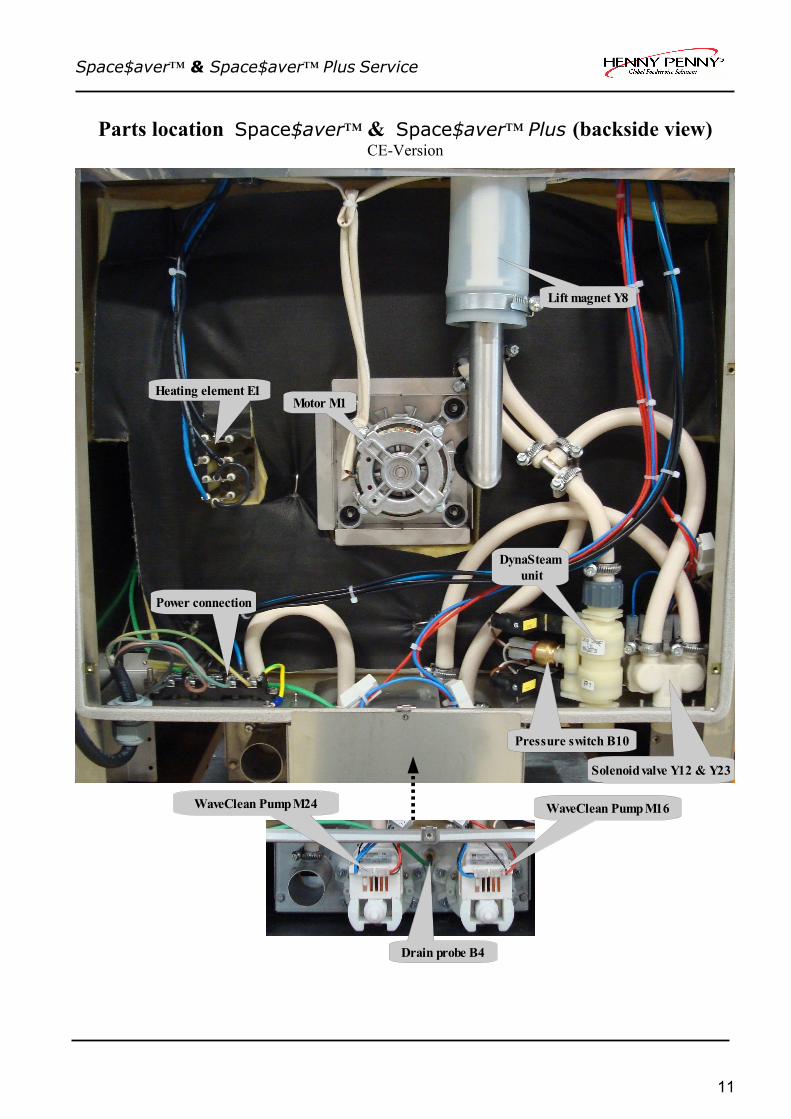
Parts location Space$aver™ & Space$aver™ Plus (backside view)CE-Version
11
Lift magnet Y8
Motor M1Heating element E1
Drain probe B4
Pressure switch B10
WaveClean Pump M16
Solenoid valve Y12 & Y23
DynaSteam unit
WaveClean Pump M24
Power connection

Space$aver™ & Space$aver™ Plus Service
The main menu (Password overview & diagnosis memory)
01.01.2015 5:55
Menu
12
1. Manual cleaning
2. WaveClean
3. HACCP
4. Setup
5. Diagnosis
6. Cookbook - USB
7. USB - cookbook
Half automatic cleaning program with presetted steps. If the cooking chamber is too hot, the appliance will be cooled automatically. If it is too cold, it is heated to the soaking temperature. Further actions(spraying cleaner, rinsing) are displayed at the respective time.
Automatic cleaning system. Three programs can be selected: (short approx. 1 hour; normal approx. 2 hours; extra approx. 3 hours)
The unit saves up to 200 HACCP logs, depending on the number of program steps.The logs can be printed out with a serial mini-printer via the RS 232 serial interface.
Password for basic adjustments: 111If the password for settings area is unknown, the area can be also entered by pushing the CombiSteam and Preheat button at the same timePassword for service area :777 Enter password with the Combi dial and confirm by pushing Start/ Stop button.
The diagnosis memory saves current and former error messages. These are represented historically according to the date and time. Turn the Combi dial to scroll inside the diagnosis memory.
Up- and download of cooking books. This feature is available from S/N 09021472 (07/2009; Software 4.xx)
Space$aver™ & Space$aver™ Plus Service
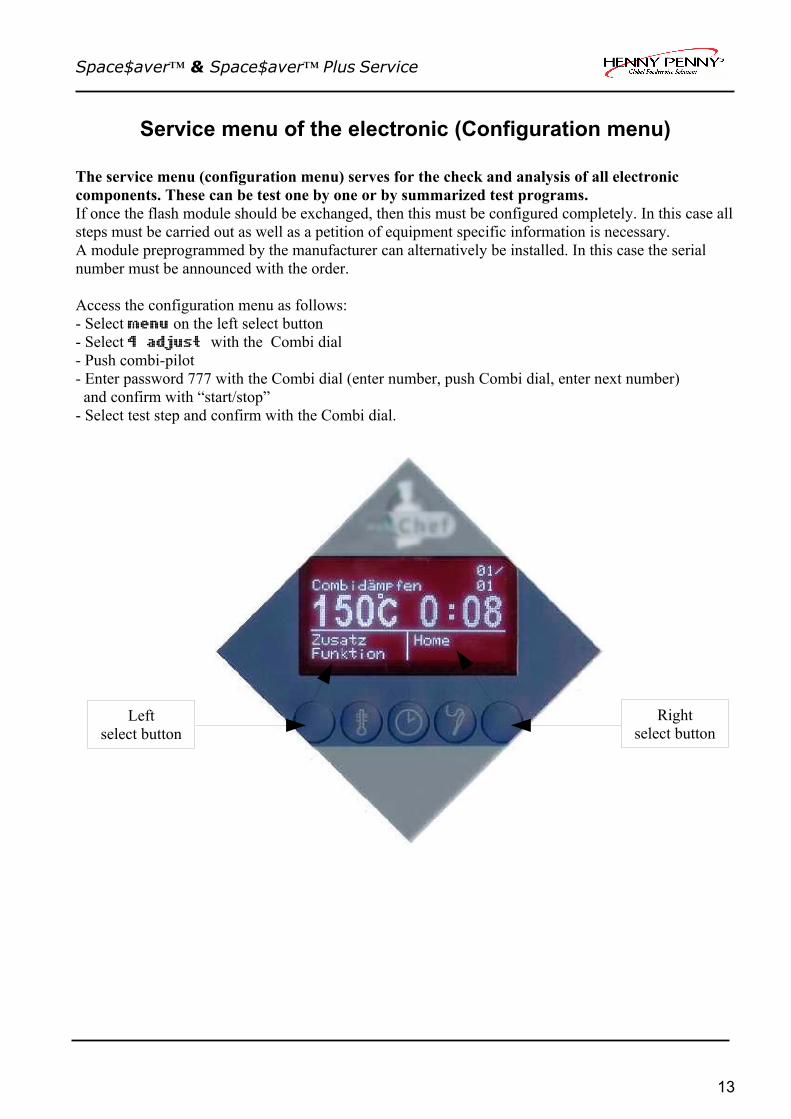
Service menu of the electronic (Configuration menu)
The service menu (configuration menu) serves for the check and analysis of all electronic components. These can be test one by one or by summarized test programs. If once the flash module should be exchanged, then this must be configured completely. In this case all steps must be carried out as well as a petition of equipment specific information is necessary. A module preprogrammed by the manufacturer can alternatively be installed. In this case the serial number must be announced with the order.
Access the configuration menu as follows:- Select menu on the left select button- Select 4 adjust with the Combi dial- Push combi-pilot- Enter password 777 with the Combi dial (enter number, push Combi dial, enter next number) and confirm with “start/stop”- Select test step and confirm with the Combi dial.
13
Leftselect button
Rightselect button

Space$aver™ & Space$aver™ Plus Service
Tabular overview of the service level (configuration I):
Name of step Short description/function 1 Software-Status Shows the installed software version and text version .
2 Display-Test Display functional test of all dots.
3 LED-Test Individual check of the LED´s on the keyboard pcb.
4 Button-Test Individual check of all keyboard buttons and the Combi dial button.
5 Relay-Test Separate check of the relays on the relay pcb. Electrical components as well as the relays can be checked on function. Display of counter readings, such as operation hours.
6 Unit configuration Input area for all unit details, such as the size of unit.
7 WaveClean-Test Test run of the automatic cleaning system for component as well functional test.
8 Fan-Test Check of all fan modes.
10 Water test Functional test for the DynaSteam unit.
11 Drain cooling Test
Functional test of the the solenoid valve and drain probe from the drain cooling system.
12 100°C+CT Calib. Calibration step for chamber and core temperature probe.
14 Empty watersystem
Water emptying function if the water connections are connected to compressed air. Made for internal use.
15 Delete error Deletes the complete diagnosis memory (not the current Error message -> see reset of electronic!).
16 Delete HACCP Deletes the complete HACCP memory
17 Delete cooking book
Deletes ALL recipes from the cooking book (incl. the default recipes!).
18 Upload cooking book
Coming soon.
19 Service Tel. This is shown by push the Smart Menu button while the unit is off.
20 Print counters Print out of all counter readings of relay test by the HACCP port.
In context of the technical further development test steps can be added or renamed. State: Software version 3.07
14

Space$aver™ & Space$aver™ Plus Service
Detailed description of the service area
1 Software-StatusThe software versions of the
• Booter • Application (software version)• Text list
are displayed.The application version is important for equipment functionality. Application = software
2 Display-TestTest patterns appear in the following cycle:
• Fully activated• Chess board 1• Chess board 2• Fully de-activated
Pressing the Combi dial button allows the individual steps to be accessed. When completed finished appears on the display.
3 LED-TestThe “ON” LED does not need to be tested, because it is already switched on. The remaining 5 LED´s (4 cooking modes and start/stop) are tested by repeated pressing of the Combi-pilot. When completed finished appears on the display.
4 Button-TestIn the button test all buttons are pressed one after the other (including the select-buttons and the Combi dial). CAUTION: Do not start with the “ON/OFF” button. Only after all buttons have pressed once it is possible to return to the configuration menu. When completed finished appears on the display.Every button is confirmed by the accompanying number on the display. If a button should be faulty the power supply must be switched off, because a return from this test is not possible anymore.
15

Space$aver™ & Space$aver™ Plus Service
5 Relay Test + Counter readingsA menu is offered with all relays of the relay pcb (K01 - K24). By pushing the Combi dialen the current condition of the chosen relay is switched over. This can be checked with the LED next to each relay. The LED signals the status on the input side of the relay (LED on = energized, LED off = not energized). The load side (output) can be controlled by measuring the outcoming voltages on terminal X5 and X6. Caution! During this test the reed contact-switch for the door is out of order! By a configuration of a new flash module a test of all relays is not required.After the relay has selected, it can be checked by pressing the Combi dial. A counter of each relay (down on the right) is shown on the display in addition. A reset of the counter is not possible.
Actor Name of step Description/ function if pushing the Combi dial button
K01 Main contactor The relay is switched on about X6.2 and can not be switched over (the unit would switches off itself ).
K02 Fan Space$aver™ Plus up to S/N 09021751 and all Space$aver™:Fan Motor M1 becomes a 230V signal by X.5.3. The fan starts in right direction.
K02 FC D0 / Fan 1 Only Space$aver™ Plus from S/N 09021752: Input D0 on the frequency converter becomes a 230V signal about X5.3. The fan motor starts on the left direction in fast speed mode.
K03 n.u. Only Space$aver™ Plus from S/N 09021752: Input D1 on the frequency converter becomes a 230V signal about X5.5. The fan motor starts on the right direction in fast speed mode.
K04 Fan l/r Space$aver™ Plus up to S/N 09021751 and all Space$aver™:Switchover for the left/ right fan direction. The fan does not run!
K05 n.u. Only Space$aver™ Plus from S/N 09021752: Input D2 on the frequency converter becomes a 230V signal about X5.9. The fan motor starts on the left direction in slow speed mode.
K06 n.u.K07 Cooling fan The relay switches the cooling fan on/off by X5.10.K08 Freash air pipe The relay energizes the lift-magnet (fresh air flap) by X6.3 (via
rectifiers V8).K09 Ext. Hood Contact for an external hood (Contact closes for 60 seconds after
opening the door). K10 Solenoid steam 1 Energizing of the DynaSteam unit by X8 (not from a relay)K11 Solenoid steam 2 Energizing of the DynaSteam unit by X8 (not from a relay)K12 Solenoid drain
coolingThe relay switches on the solenoid valve Y12 by X6.6 for drain cooling.
K13 Signal The relay switches on the buzzer H13 by X5.13.K14 n.u.K15 n.u.K16 Pump WaveClean The relay switches on the pump M16 by X6.12. The water is
pumped out of the trap into the chamber. Caution! Only carry out this step if the chamber cooled down!
K17 Reserve Relay --> see documentation reserve relay (switched by X6.13)K18 n.u. - not in use -K19 n.u. - not in use -
16

Space$aver™ & Space$aver™ Plus Service
Continuation relay test
Actor Name of step Description/ function if pushing the Combi dial button
K20 LOA B Output for the connection of an energy optimization system (terminal X2/B).
K21 Pot. free. LOA Potential free contact for an energy optimizing system (terminal X2.15 and X2.16)
K22 Illumination The relay turns the chamber illumination off/on by X5.17.
K23 Rinse WaveClean The relay energizes the solenoid valve Y23 by X6.8 for the rinsing nozzle. Caution! Only perform test at a cooled down chamber!
K24 Pump Siphon (trap)
The relay switches on the pump M24 by X6.9. The water is pumped out of the trap into to drainage.
Counter readings in the relay test:
Hours electronic Connected hours on the power supply. Hours unit on Hours which the device was in standby.Hours cooking Hours of operatingPowerfail Number of powerfails (longer than 10 sec.) during operation.
17

Space$aver™ & Space$aver™ Plus Service
6 Unit configurationThe following steps must be adjusted by the service engineer only at a new configuration of the flash modul.
Step Parameter Value range Comment6-1 Unit size/type 6.1;6.2;10.1;10.2;20.1;
20.2;6.23;6.1 compact
Adjustment of the unit sizeSpace$aver™ = 6.23Space$aver™ Plus = 6.1 compact
6-2 Heating source electric, gas Adjustment of the heating source6-3 M.-Nr. (unit no.) each 0-9 Enter the no. by turning the Combi dial;
Confirmation of each number by pushing the Combi dial. Finally confirmation by pressing the start/stop button..
6-4 WaveClean On / Off Activation / deactivation WaveClean. Default setting „on“
6-5 CT 4x On / Off Multi-point core temperature probe On / Off. “Off” = single-point Defaul setting „on“
6 PID-Parameter - Not in use6 Fan motor type Contactor 2 speed
( 6.1;10.1;20.1 contactors controlled)Contactor 1 speed(Space$afer, Space$afer PLUS) FC 2 speeds(all units with 2 speed frequency fan controller)FC 3 speeds (all units with 3 speed frequency fan controller)
Adjustment of the fan motor type. Default setting „Contactor 1 speed“.Default setting up to S/N 09021751: „Contactor 1 speed“.Default setting from S/N 09021752: „FC 3 speeds“
PHI DynaSteam On / Off On = soft water assembly with steaming unitOff = soft water assembly with pressure reducer and solenoid valve. Default setting „on“
6-6 Function code - Not in use
7 WaveClean Test
Press start appears on the display. Push the Start/ Stop button or the Combi dial to start the WaveClean test. The pump M24 pumps out the water from the trap. The trap gets filled with water by the solenoid valve Y12. This process repeats two times. The pump M16 and also fan M1 switches on and cycles the water from the trap permanently. The test can be interrupt by cancel any time. At the end of the test the trap is pumped out and filled again twice.
8 Fan Test(Space$aver™ Plus up to S/N 09021751 and all Space$aver™)
A menu with the following fan modes is offered:➢ Right fast➢ Left fast
Push the Combi dial to start with right fast. The fan speed and direction is shown on the display during the fan runs. To change left fast fan mode turn the Combi dial and push the Combi dial to confirm. Push left select button configuration menu to go back in the service area. Please note that the fan motor is not equipped with a hall sensor. No information about fan speed and direction will be shown on the display.
18

Space$aver™ & Space$aver™ Plus Service
8 Fan Test (Space$aver™ Plus with frequency controller from S/N 09021752)A menu with the following fan modes is offered: ➢ Right slow ➢ Right medium ➢ Right fast ➢ Left slow ➢ Left medium ➢ Left fast
Push the CombiPilot to start with right slow. .To change an other fan mode, turn the CombiPilot and push the CombiPilot to confirm. Push left select button configuration menu to go back in the service area.
10 Water test
Push the Combi dial to start.60 ml of water coming through the water supply pipe into the chamber now. This steps allows to check the function of the DynaSteam unit. The amount of water can be control with a measuring box. A deviation of +-8% is within the possible tolerance. A calibration is not possible/necessary because this component is complete controlled by the electronic.If the Combi dial is pushed once more, 60 ml are added up on the value on the display and another 60 ml run through the water water supply pipe.
11 Drain cooling test
The display shows the current drain temperature. Push the Combi dial to start test. Push and hold right select button Drain cooling . The manually cooling function starts and the drain temperature drops down.
19

Space$aver™ & Space$aver™ Plus Service
12. 100 C + CT probe calibration°
Caution! The CT probe and an external sensor (from temperature measuring meter) must be located in the centre of the cooking chamber.We recommend that the sensor is hung on the grill grid. The sensor tip must point upwards in order to avoid drops forming on the sensor tip. The following values are shown on the display:
For one and two-chamber units:Pressing the Combi-Plot starts the 100 °C (212°F) calibration. Before setting the offset factor for the first time, wait at least 30 minutes. When the current probe temperature shows 100 °C (± 1°C) on the display and the external temperature sensor indicates a value of between 99 °C and 99.5 °C, the unit is correctly calibrated. If the external device does not reach the temperature range specified, the temperature offset should be adjusted accordingly by turning the Combi dial. Caution! After any change to the offset setting, always wait approx. 10 minutes to allow the change to affect the cooking chamber temperature (temperature on external temperature sensor should remain stable).
When the actual temperature is at 100 °C ± 1 K, the core temperature sensor is automatically also calibrated when the calibration is finalised. If the actual temperature is outside of the specified tolerance, the following message appears: KT sensor not calibrated. For finishing the calibration press the left select button cancel .
14 Empty water systemThis step serves to empty the water inside (like valves and hoses) the system. The unit has connected to air pressure at both water connections. Now the program has to be started.This program step was conceived to avoid frost damages while transportation and is basically made for internal use.
15 Delete errorPush the right select button delete to delete the complete diagnosis momory. Press the left select key config menu to return to the configuration menu This step should be just executed at a change of ownership of the device to hold a history of all error messages from the past. This program step does not delete current faults but only the diagnostic memory! Current error messages are deleted by a reset of the electronic.
20
Current chamber temperature
Turn on time of heating circuit.(max. 1000 = 100%)
Temperature-Offsetin 0,1 °K – steps
Back to service menu

Space$aver™ & Space$aver™ Plus Service
16 Delete HACCP
On the display appears delete. Press the right select button to delete. Press the left select button config menu to return to the configuration menu. This step should be only done at a change of ownership of the device to delete the whole HACCP documentation.
17 Delete cooking book
On the display appears delete. Press the right select button to delete. Press the left select button config menu to return to the configuration menu. This step should be only done at a change of ownership of the device to delete the complete cooking book including all preprogrammed recipes!
18 Upload cooking book
At present, this program step is for the internal use only.
19 Service Tel.
This function allows to enter a service phone number.Later on the number is shown on the display by push the Smart Menu button while the unit is off.
20 Print counters
All counter readings are (below the front panel) distributed by pressing the Combi dial at the serial interface.
21

Space$aver™ & Space$aver™ Plus Service
Settings area (basic settings)
The HansDampf electronics are set to standard parameters on delivery. These standard parameterscan be changed individually within defined limits.
To enter the settings area the following steps have to be carried out: • Turn on the unit.• Push the left soft button Menu. • Select 4 Setup by turning the Combi dial. • Confirm by pushing the Combi dial. • Enter password 111 with the Combi dial (enter number, push Combi dial, enter next number)• and confirm with “start/stop”.• You are now in the settings area. With the Combi dial the desired step can be chosen. By pushing
the Combi dial this is selected.
22
Leftselect button
Rightselect button

Space$aver™ & Space$aver™ Plus Service
Description No. Setting range Explanation / function Time / Date 000 Time and date Push Combi dial button to change time
& date. Push Combi dial = selection Turn Combi dial = Change value
Temperature reading in
006 °C / °F Adjustment between temperature readings in °C or °F
Illumination blinking
023 On / Off (default = On)
Illumination flashes at the end of a program (in addition with the buzzer)
Preheat factor % 082 0 – 30 % (default =15 % )
Preheat factor if using “ready2cook“. The factor will added to the selected temperature (example: 100°C adjusted = preheating up to 115°C). This happens under consideration of the maximum temperature values.
Water maintenance liter
076 0 – 90000 liter in 100 liter-steps
(default = 0 (Off))
Attitude of the water softener capacity. Only the following situations possible:
– Separate water softener for the unit – Only the soft water connection is
connected at the filter. After the adjusted water quantity has flowed through the DynaSteam unit, a maintenance request appears on the display.
Format of date 144 Change of the shown format of date
TT = day MM = month JJJJ = year
Cookbook 097 Open / Locked / Fully locked
(default = open)
Open: Saving, changing & deleting of recepis in cooking book possible. Locked: Saving, changing & deleting of recepis in cooking book not possible. However, changes are possible after selecting recipe (before operation). Fully locked: Similar to „locked“, but no changes possible after selecting recipe (before operation).
23

Space$aver™ & Space$aver™ Plus Service
Description No. Setting range Explanation / function
Time delay fan 032 Off / On (default = off)
Push Combi dial button to change setting.Push Combi dial = selection Turn Combi dial = Change value When "On", the fan runs during thetime delay to cool the oven chamberwith a block of ice in the bottomdrawer.For this purpose, place the perforatedcontainer in the closed container, fillwith approximately 4 litres of waterand allow to freeze. Insert the iceblock into the perforated container atthe lowest level. This allows atemperature of 14°C to be maintainedfor up to 6 hours.
Cooling water 024 Minimal / Normal / Maximal (default = normal)
Setting minimal: Less water consumption but higher drain temperature and more steam from the exhaust pipe.Setting maximal: More water consumption but lower drain temperature and less steam from the exhaust pipe.
Time ext. hood 083 0 – 600 seconds (default = 60 seconds)
Time where the external condensation hood runs to maximum performance after the chamber door was opened.
Time signal (s) 084 0 – 180 seconds (default = 20 seconds)
Time of the buzzer/ flashing illumination at the end of a program.0= buzzer off. In addition to the buzzer the flashing illumination can deactivated / activated. See also parameter 023.
Altitude 015
0-500 m; 501 – 1000 m; 1001 – 1500 m; > 1500 m (default = 0)
Altitude adjustment (above sea level).
Password 096 000 – 500 (default = 111)
Individual passwords can be set up inthis here.
Scroll direction 225 Normal / Clockwise (default = normal=)
The direction of the Combi dial can beadjusted as required in the menus andcookbook.
24
Space$aver™ & Space$aver™ Plus Service
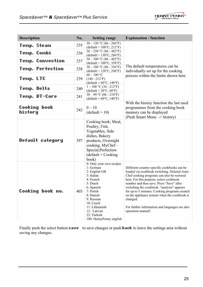
Description No. Setting range Explanation / function
Temp. Steam 235 30 – 130 °C (86 - 266°F)(default = 100°C, 212°F)
Temp. Combi 236 30 – 250 °C (86 - 482°F)(default = 130°C, 266°F)
Temp. Convection 237 30 – 300 °C (86 - 482°F)(default = 180°C, 358°F)
Temp. Perfection 238 30 – 180 °C (86 - 356°F)(default = 120°C, 248°F)
Temp. LTC 239 60 – 100 °C (140 - 212°F)(default = 60°C, 140°F)
Temp. Delta 240 1 – 100 °C (34 - 212°F)(default = 20°C, 68°F)
Temp. DT-Core 241 30 – 99 °C (86 - 210°F)(default = 60°C, 140°F)
The default temperatures can beindividually set up for the cookingprocess within the limits shown here
Cooking book history 242 0 – 10
(default = 10)
With the history function the last used programmes from the cooking book memory can be displayed (Push Smart Menu -> history)
Default category 397
Cooking book; Meat, Poultry, Fish, Vegetables, Side dishes, Bakery products, Overnightcooking, MyChef – Special;Perfection(default = Cooking book)
Cooking book no. 403
0: Only your own recipes1: German2: English GB3: Italian4: French5: Dutch6: Spanish7: Polish8: Danish9: Russian10: Czech11: Lithuaniab12: Lativan22: Turkish100: HennyPenny english
Different country-specific cookbooks can beloaded via cookbook switching. Deleted Auto-Chef cooking programs can also be restoredhere. For this purpose, select cookbooknumber and then save. Press "Save" afterswitching the cookbook. "analysis" appearsfor up to 5 minutes. Cooking programs created on the appliance remain when the cookbook is changed.
For further information and languages see also operation manual!
Finally push the select button save to save changes or push back to leave the settings area without saving any changes.
25

Space$aver™ & Space$aver™ Plus Service
Generally measurement mask
This mask shows you a summary of measurement information during preheating and cooking process.
By press and hold the Combi dial during operation for a short time, you can see the following information until pushing the left soft button „back“.
26
chamber temperature [°C/°F Heat deamand [%] Electronic
temperature
Temperaturedrain probe
Core temperatures 1-4
Air flap demand Z0= close Z1= open
Water injection(steam)demand B0= Off B1= On
Drain coolingdemand W0= Off W1= On
No function

Space$aver™ & Space$aver™ Plus Service
How to activate and disable the demo mode
Activate demo mode:
→ Press the
ON / OFF button for 16 seconds during the combi steamer is off. The appliance is in the demo mode now.
Disable demo mode:
→ Press the
ON / OFF button for 16 seconds during the combi steamer is off. The appliance is back in the normal mode now.
Reset of the electronic
→ press the
ON / OFF button for 8 seconds during the combi steamer is on. The electronic will be reset now. After 8 second the notice “loading Flash data” will be on the display. It means that the electronic loads the data’s from the flash-module to the RAM.
27

Space$aver™ & Space$aver™ Plus Service
How to change the display language
For changing the display language, please do the following steps:• Switch the unit on by pressing the “ON/Off” button.• Press the left soft key “Menu” • Then select step 4 “settings” with the combi pilot.• If you press the right soft key “Language” you can change the display language with the combi
pilot.• Please confirm the requested language by pressing the right soft key “save”.• Then press the right soft key twice. Now you are back in the main menu
28
Space$aver™ & Space$aver™ Plus Service
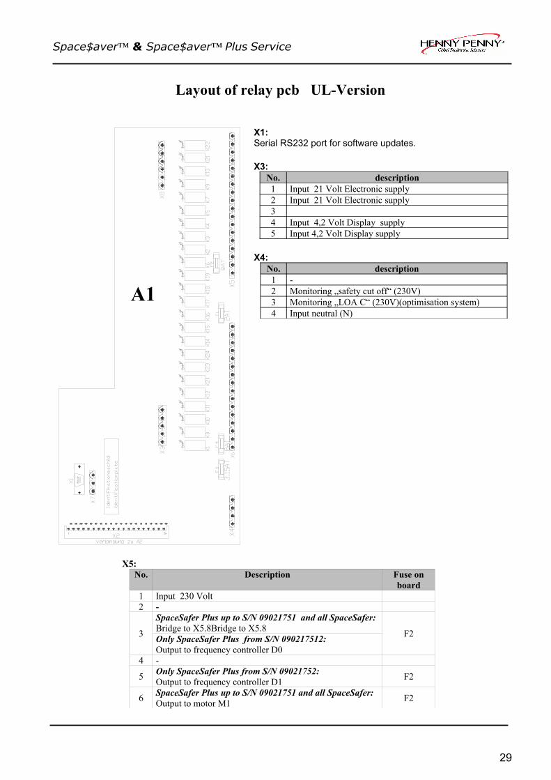
Layout of relay pcb UL-Version
X5:No. Description Fuse on
board1 Input 230 Volt2 -
3
SpaceSafer Plus up to S/N 09021751 and all SpaceSafer:Bridge to X5.8Bridge to X5.8Only SpaceSafer Plus from S/N 090217512:Output to frequency controller D0
F2
4 -
5 Only SpaceSafer Plus from S/N 09021752:Output to frequency controller D1 F2
6 SpaceSafer Plus up to S/N 09021751 and all SpaceSafer:Output to motor M1 F2
29
A1
X1:Serial RS232 port for software updates.
X3:No. description1 Input 21 Volt Electronic supply2 Input 21 Volt Electronic supply3 4 Input 4,2 Volt Display supply5 Input 4,2 Volt Display supply
X4:No. description1 -2 Monitoring „safety cut off“ (230V)3 Monitoring „LOA C“ (230V)(optimisation system)4 Input neutral (N)

Space$aver™ & Space$aver™ Plus Service
X5 (continuation):No. Description Fuse on
board
7 SpaceSafer Plus up to S/N 09021751 and all SpaceSafer:Output to motor M1 F2
8 SpaceSafer Plus up to S/N 09021751 and all SpaceSafer:Bridge to X5.3 F2
9 Only SpaceSafer Plus from S/N 09021752:Output to frequency controller D2 F2
10 Output to cooling fan M7 F211 Connection for external exhaust hood (signal contact)12 Connection for external exhaust hood (signal contact)13 Output to buzzer H1314 Input 24 Volt (buzzer supply)15 Potential free contact16 Potential free contact17 Output to chamber illumination18 Input 10,7V for chamber illumination
X6:No. Description Fuse on
board1 Input 230 Volt2 Output to F7 limit switch /main contactor F33 Output to V8 rectifier / Y8 lift magnet F44 - F45 - F46 Output to solenoid valve Y12 (drain cooling) F47 Output for Energy optimisation system8 Output to solenoid valve Y23 (AutoShower) F49 Output to cleaning pump M24 F410 -11 -12 Output to cleaning pump M16 F413 Output to reserve relay K1714 -15 -16 -
X7:No. Description1 Buzzer supply voltage to X5.142 Buzzer supply voltage
X8:No. Description1 Output signal DynaSteam unit Y10 / Y20 (Y20 only 20.x)2 Output signal DynaSteam unit Y10 / Y20 (Y20 only 20.x)3 -4 Output signal DynaSteam unit Y11 / Y21 (Y21 only 20.x)5 Output signal DynaSteam unit Y11 / Y21 (Y21 only 20.x)9 -
Fuses: F1: 2A Slow blow #203474; F2,F4: 8A Slow blow #203741; F3: 3,15A Slow blow #203742
30

Space$aver™ & Space$aver™ Plus Service
Layout of relay pcb CE-Version CE-Version
X5:No. Description Fuse on
board1 Input 230 Volt2 -
3
SpaceSafer Plus up to S/N 09021751 and all SpaceSafer:Bridge to X5.8Only SpaceSafer Plus from S/N 090217512:Output to frequency controller D0
F2
4 -5 Only SpaceSafer Plus from S/N 09021752:
Output to frequency controller D1 F2
6 SpaceSafer Plus up to S/N 09021751 and all SpaceSafer:Output to motor M1Output to motor M1
F2
31
A1
X1:Serial RS232 port for software update.
X3:No. description1 Input 21 Volt Electronic supply2 Input 21 Volt Electronic supply3 4 Input 4,2 Volt Display supply5 Input 4,2 Volt Display supply
X4:No. description1 -2 Monitoring „safety cut off“ (230V)3 Monitoring „LOA C“ (230V)(optimisation system)4 Input neutral (N)

Space$aver™ & Space$aver™ Plus Service
X5 (continuation):No. Description Fuse on
board
7 SpaceSafer Plus up to S/N 09021751 and all SpaceSafer:Output to motor M1 F2
8 SpaceSafer Plus up to S/N 09021751 and all SpaceSafer:Bridge to X5.3 F2
9 Only SpaceSafer Plus from S/N 09021752:Output to frequency controller D2 F2
10 Output to cooling fan M7 F211 Connection for external exhaust hood (signal contact)12 Connection for external exhaust hood (signal contact)13 Output to buzzer H1314 Input 230 Volt (buzzer supply)15 Potential free contact16 Potential free contact17 Output to chamber illumination18 Input 10,7V for chamber illumination
X6:No. Description fuse on
board1 Input 230 Volt2 Output to F7 limit switch /main contactor F33 Output to V8 rectifier / Y8 lift magnet F44 - F45 - F46 Output to solenoid valve Y12 (drain cooling) F47 Output for Energy optimisation system8 Output to solenoid valve Y23 (AutoShower) F49 Output to cleaning pump M24 F410 -11 -12 Output to cleaning pump M16 F413 Output to reserve relay K1714 -15 -16 -
X7:No. Description1 Not in use2 Not in use
X8:No. Description1 Output signal DynaSteam unit Y10 / Y20 (Y20 only 20.x)2 Output signal DynaSteam unit Y10 / Y20 (Y20 only 20.x)3 -4 Output signal DynaSteam unit Y11 / Y21 (Y21 only 20.x)5 Output signal DynaSteam unit Y11 / Y21 (Y21 only 20.x)9 -
Fuses: F1: 2A Slow blow #203474; F2,F4: 8A Slow blow #203741; F3: 3,15A Slow blow #203742
32

Space$aver™ & Space$aver™ Plus Service
Layout of keyboard pcb
X1:Connection to relay pcb A1
X5: HACCP connection
X2:No. Description LED on board
1 Solid state relay (SSR) V1 (brown)
2 Solid state relay (SSR) V1 (white)PWM1
3 Reed contact (door) switch S1 (black)
4 Reed contact (door) switch S1 (black)IN 1
5 Pressure switch B10 (white)
6 Pressure switch B10 (white)IN 4
X6:Combi dial connection
X11:No. Description
1 Chamber probe B2 (black)
2 Chamber probe B2 (brown)
3 Drain probe B4 (white)
4 Drain probe B4 (green)
X16:No. Description
1 Core temperature probe B1 (white)
2 Core temperature probe B1 (green/red)
3 Core temperature probe B1 (green/blue)
4 Core temperature probe B1 (green/yellow)
5 Core temperature probe B1 (green)
33
Flashing LED: 1 0 1 0ResetOut LED: 1 0 0 1
Booteractiv
nosoftware
Booteractiv
nosoftware
If the flashing LED flashes equally (in 1 Hz-time) theprocessor runs.If the flashing LED has a higher flash frequency, reset theelectronic.

Space$aver™ & Space$aver™ Plus Service
Fuse protection schematicValid for all Space$aver™ and Space$aver™ Plus up to S/N 0902xxxx
*= Only at CE units (The UL version has a low voltage buzzer)
Part numbers of fuses:Fuse on the electric assembly:F4, 10A slow blow = #203996Fuses on the transformer:0,8A slow blow = #2037201,25A slow blow = #203722Fuses on the relay pcb:F2, F4 8A slow blow = #203741F3 3,15A slow blow = #203742
34
F4 (10A)230V
F2 (8A)230V
Cooling fan M7
F3 (3,15A)230V
F4 (8A)230V Solenoid valve Y12 / Y23
Pump M24
Pump M16
Reserve relay K17
Supply voltage forrelay pcb A1
0,8A 4,2V
1,25A 21V
3,15A 10,7V
Supply voltage for display on the keyboard pcb
Supply voltage for chamber illumination H1
Chamber high limit temp. switch F7
Fan motor high limit temp. switch F6
Main contactor K1
Rectifier V8 Lift magnetY8
Transformer T1
Relay pcb A1
Buzzer H13*

Space$aver™ & Space$aver™ Plus Service
Fuse protection schematicValid for Space$aver™ Plus from S/N 0902xxxx
*= Only at CE units (The UL version has a low voltage buzzer)
Part numbers of fuses:Fuse on the electric assembly:F4, F4.1 10A slow blow = #203996Fuses on the transformer:0,8A slow blow = #2037201,25A slow blow = #203722Fuses on the relay pcb:F2, F4 8A slow blow = #203741F3 3,15A slow blow = #203742
35
F4 (10A)230V
F2 (8A)230V
Cooling fan M7
F3 (3,15A)230V
F4 (8A)230V Solenoid valve Y12 / Y23
Pump M24
Pump M16
Reserve relay K17
Supply voltage forrelay pcb A1
0,8A 4,2V
1,25A 21V
3,15A 10,7V
Supply voltage for display on the keyboard pcb
Supply voltage for chamber illumination H1
Chamber high limit temp. switch F7
Fan motor high limit temp. switch F6
Main contactor K1
Rectifier V8 Lift magnetY8
Transformer T1
Relay pcb A1
Buzzer H13
Power supply frequency controller V10
F4.1 (10A) 230V
*

Space$aver™ & Space$aver™ Plus Service
Rewiring instructions for reserve relay K 17
The power board is equipped with a reserve relay which can be covered at a relay failure. This concerns only closing contacts these are not potential-free. The assignment happens in the relay test of the configuration menu. It is to proceed as follows:- Identifying faulty relay by using the relay test. - Assigning the reserve relay by pressing the reserve button. - Leaving the relay test by pressing the Config menu button.- Press save button and leave the configuration menu with the back button and rewire in accordance with table.Please, after the cable became rewired in accordance with table, write on it !!
Terminal connection
Contact type
Protected by
Actor name Actor Comments / rewiring instructions
X5.1 Input F4 230V input on F11 and F2 Protection by fuse F4 on electric assemblyX5.3 N. O. F2 Fan / FC D0 K2 Rewire cable from X5.3 to X6.13 and
assign reserve relay.X5.5 N.O. F2 FC D01 K3 Rewire cable from X5.5 to X6.13 and
assign reserve relay.X.5.6 N.C.X5.7 N.O.X5.8 Input
Potential- free
Fan left / right K4 Not possible for reserve relay assignment
X5.9 N. O. F2 FC D2 K5 Rewire cable from X5.10 to X6.13 and assign reserve relay.
X5.10 N. O. F2 Cooling fan K7 Rewire cable from X5.10 to X6.13 and assign reserve relay.
X5.11 N. O.X5.12 Input
Potential-free
External hood K9 Not possible for reserve relay assignment
X5.13 N. O.X5.14
Potential-free
Buzzer K13 Not possible for reserve relay assignment
X5.15 N. O.X5.16 Input
Potential-free
For external energy optimisation system
K21 Not possible for reserve relay assignment
X5.17 N. O.X5.18 Input
Potential-free
Illumination K22 Not possible for reserve relay assignment
X6.1 Input F4 230V input on F3 and F4 Protection by fuse F4 on electric assemblyX6.2 N. O. F3 Main contactor K1 Rewire cable from X6.2 to X6.13 and
assign reserve relay.X6.3 N. O. F4 Lift magnet (fresh air flap) K8 Rewire cable from X6.3to X6.13 and
assign reserve relay.X6.6 N. O. F4 Solenoid valve drain
coolingK12 Rewire cable from X6.6 to X6.13 and
assign reserve relay.X6.7 N. O. F4 Energy optimisation system
(B)K20 Rewire cable from X6.7 to X6.13 and
assign reserve relay.X6.8 N.O. F4 Rinse WaveClean K23 Rewire cable from X6.7 to X6.13 and
assign reserve relay.X6.9 N. O. F4 Siphon pump (trap pump) K24 Rewire cable from X6.9 to X6.13 and
assign reserve relay.X6.12 N. O. F4 WaveClean pump K16 Rewire cable from X6.12 to X6.13 and
assign reserve relay.X6.13 N. O. F4 Reserve relay K17 Reserve relay N. C. = normally closed contact N. O. = Normally open contactReorganisation and reprogramming into the default situationTo „charge“ the reserve relay not unnecessary,an exchange of the relay circuit board to the default situation should be established again. Procedure:
➢ Establish original state of the wiring (from X6.13 back to X ... ) .➢ Select relay test in the configuration menu.➢ Select relay K17 and push the reserve button.➢ Leave the relay test by pushing the config-menu button.➢ Push save and leave the configuration menu with back.
36

Space$aver™ & Space$aver™ Plus Service
37

Space$aver™ & Space$aver™ Plus Service
38
Error messages

Space$aver™ & Space$aver™ Plus Service
Overview of the emergency programs
In case of an error the electronic switches in a emergency mode automatically This function ensures, that the unit works at least in the main modes.„Emergency program“ is shown on display in the main mask.
Every program arises from a previous temperature sensor error message.The message "emergency program" can be deleted by a reset of electronic only.
Overview
Error message in the diagnosis ConsequenceCore temp. probe defectCT1-probe defectCT2-probe defectCT3-probe defectCT4-probe defect
The core temperature probe function is not available.
Temp. probe chamber 1 defect The core temp. probe is used as a chamber probe now. The core temperature probe function is not available. Due the position of the core temp. probe easy temperature differences of the chamber temperature measurement are possible.
Drain temp. probe defect The drain cooling changes in an emergency program (Controlled by the pcb). An increased water consumption arises from it.
39

Space$aver™ & Space$aver™ Plus Service
The diagnosis memory
The diagnosis memory offers a very easy possibility to demand current and former error messages. These are represented historically according to the date and time.Enter the diagnosis area as follows:
Press the ON/OFF button.
Press left select button menu
Select 5 diagnosis with the CombiPilot (knob). Enter diagnosis area by pressing the right select button confirm or the CombiPilot.
40
Date Time
MenuSoft-key
leftSoft-key
right
Menu
5 Diagnosis (flashs)
MenuSoft-key
leftSoft-key
right

Space$aver™ & Space$aver™ Plus Service
Temperature probe chamber 1 defect
Consequence:The electronic changes in an emergency program automatically. The core temp. probe takes over the function of the chamber probe. The core temp. probe function is not available.
Position of the chamber probe:Upper chamber area, on the right
Designation of the component(s) in the wiring diagram: B2
Troubleshooting:
Functional test:
The measurements values can be demand with the service status mask.
Finally receipt the error message by a reset of the electronic!
41
Check contacting at plug X11 on the keyboard card A2 (also between plug and cable). Reset the electronic. Mistakes cleared?
No
Check occupancy of the probe at plug X11 (see also wiring diagram). Reset the electronic. Mistakes cleared?
No
Change chamber probe. Mistakes cleared?
Change keyboard card
No

Space$aver™ & Space$aver™ Plus Service
Core temperature probe defectCT1 probe defect CT2 probe defectCT3 probe defectCT4 probe defect
Consequence:The electronic changes in an emergency program automatically. The function of the probe is deactivated.
Position of the core temp. probe:In the front of the chamber.
Designation of the component in the wiring diagram: B1
Troubleshooting:
Functional test:The measurements values can be demand with the service status mask.
Finally receipt the error message by a reset of the electronic!
42
Check contacting at plug X16 on the keyboard card A2 (also between plug and cable). Reset the electronic. Mistakes cleared?
No
Check occupancy of the probe at plug X16 (see also wiring diagram). Reset the electronic. Mistakes cleared?
No
Check if the core temp probe. is mechanical damaged. Change probe if necessary.
Change keyboard card
No

Space$aver™ & Space$aver™ Plus Service
Drain temperature probe defect
Consequence:The electronic changes automatically in an emergency program. The drain cooling switches on and off controlled by the electronic (During operation).
Position of the drain temperature probe:The probe is located at the syphon.
Designation of the component in the wiring diagram: B4
Troubleshooting:
Functional test:Enter the service menu and select „11 Drain cooling test“.
Finally receipt the error message by a reset of the electronic!
43
Check contacting at plug X11 on the keyboard card A2 (also between plug and cable). Reset the electronic. Mistakes cleared?
No
Check occupancy of the probe at plug X11 (see also wiring diagram). Check function with the help of the service menu, 11 drain cooling test The displayed temperature must decrease during active vapour cooling. The displayed temperature increases at wrong connection ! Reset the electronic. Mistakes cleared?
Change keyboard card
No
Change drain probe. Mistake cleared?
No

Space$aver™ & Space$aver™ Plus Service
Over temperature cooking chamber
Consequence:The unit is not ready for operating until the unit has cooled down.
Error description: A temperature of >310°C (590°F) were measured in the chamber by the Core temp. probe or camber probe.Troubleshooting:
44
Open the hood. Maybe the solid state relay switches the power permanently (short-circuit). Switch the unit on (standby) and check current consumption / voltage at the load side of the SSR. Is there a current flow / would voltage put through and the green LED on the SSR´s are off?
Replace broken solid state relay. Check if the fan wheel is out of balance.
Yes
Switch the unit on (standby) and check current consumption / voltage at the load side of the SSR. Is there a current flow / would voltage put through and one of the green LED on the SSR´s is on?
There is an error on the keyboard pcb. LED PWM 1 is permanently on. (control of the SSR´s). Replace keyboard pcb.Yes
Check contacts of the probes at the plug X11 and X16 at display pcb A2. (also between plug and cable). Reset the electronic. Mistakes cleared?
Observe the shown temperatures in the measurement mask. Maybe one probe has broken.
Is "emergency program" shown on the display? Enter the diagnosis memory The core temp. probe has placed into the product during the unit was into the emergency program.. See also error „CT-probe defect“. Yes
No
No
No
No

Space$aver™ & Space$aver™ Plus Service
Electronic too hotElectronic overheated
Consequence / description:Error: “Electronic too hot:The measured temperature of electronics amounts to at least 70°C (158°F). The cooked program is stopped.
Error “Electronic overheated”:The measured temperature of electronics amounts to at least 80°C (176°F). The oven switches off itself. After cooling down the device is operational again.
Position of the temperature probe:The probe is located on the keyboard pcb on board. This cannot be exchanged one by one.
Troubleshooting:
45
No
Clean fresh air area.
Does the cooling fan work? Check the function of relay K7 with the help of the relay test. In the service area. No
Are 230 V at the supply of the cooling fan during the unit is running?
Is the fresh air area free of dirt (backside)?
Yes
No
Check the function of relay K7 with the help of the relay test. (Voltage measurement at the respective outputs). If the relay is broken, the „reserve relay“ function can be use. Exchange relay pcb if necessary.
Yes
Exchange cooling fan.A device which produces high temperatures is next to the unit. Change local situation.
No

Space$aver™ & Space$aver™ Plus Service
Reference temperature probe defect
Consequence:The unit is out of order. The reference temp. probe on the keyboard card has broken.
Troubleshooting:Change keyboard card
Ice damage risk
Consequence:The unit is out of order. A temperature of < 0°C (32°F) has measured on the keyboard pcb.
Position of the temperature probe:The probe is located .
Troubleshooting:Ensure that the temperature next to the unit is not less than < 0°C (32°F). Perhaps change oven location.
Caution! There is a high risk that water pressurized components were damaged.
Battery empty
Consequence / description:The battery on the display card is empty. The battery is located on the display side of the electronic. The oven can be operated but the following functions are not available:– If the unit is not connected at the power supply (power failure) the date and time get lost.– Furthermore the adjustments of the autostart function get lost.
WaveClean interrupted
Consequence / description:The cleaning program was stopped by the user manually.
If another error message turns up in the diagnosis loft at the same time, this is the cause of the interruption (such as error "no water").
46

Space$aver™ & Space$aver™ Plus Service
Chamber high limit
Consequence:The unit is out of order.
Error description: A temperature of >315°C (599°F) electric unit or 275°C (527°F) were in the chamber. The safety limit switch has triggered and must be reset manually. The reason must be identified in addition.
Position of the safety limit switch:The part is located at the upper outer wall of chamber (behind the chamber isolation).
Designation of the component in the wiring diagram: F7
Troubleshooting:
47
Reset the safety limit switch. Maybe a solid state relay (SSR) switches the power permanently (short-circuit). Switch the unit on (standby) and check current consumption / voltage at the load side of the SSR. Is there a current flow / would voltage put through and the green LED on the SSR´s are off?
Open the hood. Has the safety switch triggered ?
Yes
No
Replace broken solid state relay. Check if the fan wheel is out of balance.
NoYes
Switch the unit on (standby) and check current consumption / voltage at the load side of the SSR. Is there a current flow / would voltage put through and one of the green LED on the SSR´s is on?
Yes
There is an error on the keyboard pcb. LED PWM 1 or PWM 2 is permanently on. (control of the SSR´s). Replace keyboard pcb.
No
Is "emergency program" shown on the display?
Enter the diagnosis memory The core temp. probe has placed into the product during the unit was into the emergency program.. See also error „CT-probe defect“.
Yes
Continuation on the next page
Continuation on the next page

Space$aver™ & Space$aver™ Plus Service
Continuation error chamber high limit
48
Check the voltage at plug X4 on the relay pcb. Switch the unit on. Are 230V available at X4.2? No
Is the safety switch ok? (continuity test during the unit is disconnected from the power supply) ?
NoReplace safety limit switch
Functional test from relay K1at the relay pcb (Input X6.1; Output X.6.2. Replace relay pcb if necessary.
YesYes
Check if the neutral connection (N) is available at plug X4.1.
Enter a program in any mode and push Start/Stop. Does the fan motor M1 start?
Check fuse F2 on the relay pcb.
Check capacitor (shortcut?)
Check the cooling fan M7 (shortcut)
Check fan motor M1 and replace, if necessary.

Space$aver™ & Space$aver™ Plus Service
No water
Description:The error message appears only during steaming and WaveClean mode. The error only appears if the pressure switch realised a water pressure less than 1bar (14.5 psi). The contact opens and the error message appears on the display.Consequence:„Steaming“ mode: After confirmation of the error message the program can be continued. „WaveClean“ mode: Cleaning process is stopped and „WaveClean interrupted“ is displayed.. An cancellation program starts automatically.
Troubleshooting:
49
Ja
Is the on site water supply available?
Carry out step 10 „water test“ in the service area. Is steam built up in the chamber /water injected over the supply pipe in the chamber?
Yes
Yes
Is the water inlet filter at the water connection and at the steaming unit present and free of dirt?
No
No
Ensure water supply. The water flow pressure must be at least 1,5bar (21.8 psi).
Clean or replace filter No
Yes
No
Are both solenoid valves of the water steaming unit energized?
Carry out step 10 „water calibration“ in the service area. Are 60 ml (+- 8%) coming out of the water supply pipe ( examine with measuring container)?
Check / change pressure switch.
No
YesCheck the coils and plugs. (continuity test). Exchange coil or water steaming unit.

Space$aver™ & Space$aver™ Plus Service
HW-Fail Temp UREF0 to high
Error description: The error signalled, that the supply line is disturbed on the circuit board and/or from sensors. A sensor has a very low resistor or direct chassis ground contact with the frame.
The first possibility is likely if the fault occurs during WaveClean or in steaming mode. Explanation: The water gets into the probe and builds up an electric connection between the probe itself and the chassis. Through this connection a voltage potential from the chassis reaches the temperature inputs of the keyboard pcb and causes the malfunction.
Troubleshooting:Disconnect the following components one by one to identify the faulty component: – Pressure switch B10 at the steaming unit– Core temperature probe B1– Drain probe B4– Chamber probe B2
If the fault appears only at the automatic cleaning WaveClean, the drain probe B4 is probably the cause.
Error Power board
Description: There is a communication error between keyboard and relay pcb.
Troubleshooting:
Waterfilter maintenance
The water quantity maintenance was activated in the user level (password 111). The adjusted water quantity has flown by the soft water assembly. Change water softener and enter the capacity in the corresponding level (password 111, water limit maintenance).
50
Check power supply of the relay card (transformer T1 and relay card plug X3). Also see „Layout of the relay card“
Change relay pcb. Change keyboard pcb.. Mount the old relay pcb again.
Check power supply of the relay card (transformer T1 and relay card plug X3). Also see „Layout of the relay card“
Change relay pcb. Change keyboard pcb.. Mount the old relay pcb again.

Space$aver™ & Space$aver™ Plus Service
51

Space$aver™ & Space$aver™ Plus Service
52