SERVICE STATION MANUAL Vespa LX - S 125 3V ie 150 3V ... 3v...SERVICE STATION MANUAL Vespa LX - S...
251
SERVICE STATION MANUAL 677662 EN Vespa LX - S 125 3V ie 150 3V ie (2012)
Transcript of SERVICE STATION MANUAL Vespa LX - S 125 3V ie 150 3V ... 3v...SERVICE STATION MANUAL Vespa LX - S...
SERVICE STATION MANUAL677662 EN
Vespa LX - S 125 3V ie 150 3V ie (2012)
SERVICE STATIONMANUAL
Vespa LX - S 125 3V ie 150 3V ie (2012)
The descriptions and images in this publication are given for illustrative purposes only and are not binding.While the basic specifications as described and illustrated in this manual remain unchanged, Piaggio
Việt Nam reserves the right, at any time and without being required, to update this publication beforehand,to make any changes to components, parts or accessories, which it considers necessary to improve the
product or which are required for manufacturing or construction reasons.Not all versions/models shown in this publication are available in all countries. The availability of each
model should be checked at the official Piaggio sales network."© Copyright 2013 - PIAGGIO VIỆT NAM. All rights reserved. Reproduction of this publication in whole
or in part is prohibited."PIAGGIO VIỆT NAM- After Sales
LOT M - BINH XUYEN INDUSTRIAL ZONE - VINCH PHUC - VIET NAMCUSTOMER SERVICE CENTREPlease contact with us following:
Hot line: 1800 5555 85Email:
www.piaggio.com.vn
SERVICE STATION MANUALVespa LX - S 125 3V ie 150 3V ie
(2012)
This service station manual has been drawn up by Piaggio & C. Spa to be used by the workshops ofPiaggio dealers. It is assumed that the user of this manual for maintaining and repairing Piaggio vehicleshas a basic knowledge of mechanical principles and vehicle repair technique procedures. Any significantchanges to vehicle characteristics or to specific repair operations will be communicated by updates tothis manual. Nevertheless, no mounting work can be satisfactory if the necessary equipment and toolsare unavailable. It is therefore advisable to read the sections of this manual concerning special tools,along with the special tool catalogue.
N.B. Provides key information to make the procedure easier to understand and carry out.
CAUTION Refers to specific procedures to carry out for preventing damages to the vehicle.
WARNING Refers to specific procedures to carry out to prevent injuries to the repairer.
Personal safety Failure to completely observe these instructions will result in serious risk of personalinjury.
Safeguarding the environment Sections marked with this symbol indicate the correct use of the vehicleto prevent damaging the environment.
Vehicle intactness The incomplete or non-observance of these regulations leads to the risk of seriousdamage to the vehicle and sometimes even the invalidity of the guarantee.
INDEX OF TOPICS
CHARACTERISTICS CHAR
TOOLING TOOL
MAINTENANCE MAIN
TROUBLESHOOTING TROUBL
ELECTRICAL SYSTEM ELE SYS
ENGINE FROM VEHICLE ENG VE
ENGINE ENG
INJECTION INJEC
SUSPENSIONS SUSP
BRAKING SYSTEM BRAK SYS
CHASSIS CHAS
PRE-DELIVERY PRE DE

INDEX OF TOPICS
CHARACTERISTICS CHAR
This section describes the general specifications of the vehicle.
Rules
This section describes general safety rules for any maintenance operations performed on the vehicle.
Safety rules
- If work can only be done on the vehicle with the engine running, make sure that the premises are well
ventilated, using special extractors if necessary; never let the engine run in an enclosed area. Exhaust
fumes are toxic.
- The battery electrolyte contains sulphuric acid. Protect your eyes, clothes and skin. Sulphuric acid is
highly corrosive; in the event of contact with your eyes or skin, rinse thoroughly with abundant water
and seek immediate medical attention.
- The battery produces hydrogen, a gas that can be highly explosive. Do not smoke and avoid sparks
or flames near the battery, especially when charging it.
- Fuel is highly flammable and it can be explosive given some conditions. Do not smoke in the working
area, and avoid naked flames or sparks.
- Clean the brake pads in a well-ventilated area, directing the jet of compressed air in such a way that
you do not breathe in the dust produced by the wear of the friction material. Even though the latter
contains no asbestos, inhaling dust is harmful.
Maintenance rules
- Use original PIAGGIO spare parts and lubricants recommended by the Manufacturer. Non-original or
non-conforming spares may damage the vehicle.
- Use only the appropriate tools designed for this vehicle.
- Always use new gaskets, sealing rings and split pins upon refitting.
- After removal, clean the components using non-flammable or low flash-point solvents. Lubricate all
the work surfaces, except tapered couplings, before refitting these parts.
- After refitting, make sure that all the components have been installed correctly and work properly.
- Use only equipment with metric sizes for removal, service and reassembly operations. Metric bolts,
nuts and screws are not interchangeable with coupling members using English measurements. Using
unsuitable coupling members and tools may damage the vehicle.
- When carrying out maintenance operations on the vehicle that involve the electrical system, make
sure the electrical connections have been made properly, particularly the ground and battery connec-
tions.
Vespa LX - S 125 3V ie 150 3V ie (2012) Characteristics
CHAR - 7
Vehicle identification
THE FOLLOWING INDICACTIONS REFER TO THE LX VERSION.
VEHICLE IDENTIFICATION VESPA LXSpecification Desc./Quantity
Chassis prefix (125) ZAPM68300 - 10000001Engine prefix (125) M669M 1001Chassis prefix (150) ZAPM68400 - 10000001Engine prefix (150) M66AM - 1001
THE FOLLOWING INDICACTIONS REFER TO THE S VERSION.
VEHICLE IDENTIFICATION VESPA SSpecification Desc./Quantity
Chassis prefix (125) ZAPM68301 - 10000001Engine prefix (125) M669M 1001Chassis prefix (150) ZAPM68401 - 10000001Engine prefix (150) M66AM - 1001
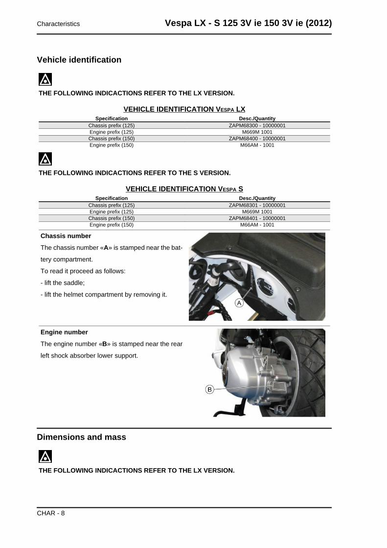
Chassis number
The chassis number «A» is stamped near the bat-
tery compartment.
To read it proceed as follows:
- lift the saddle;
- lift the helmet compartment by removing it.
Engine number
The engine number «B» is stamped near the rear
left shock absorber lower support.
Dimensions and mass
THE FOLLOWING INDICACTIONS REFER TO THE LX VERSION.
Characteristics Vespa LX - S 125 3V ie 150 3V ie (2012)
CHAR - 8
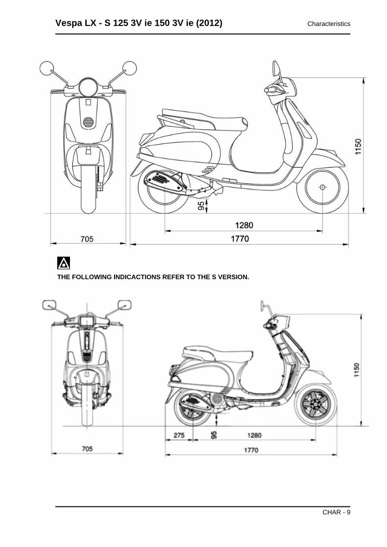
THE FOLLOWING INDICACTIONS REFER TO THE S VERSION.
Vespa LX - S 125 3V ie 150 3V ie (2012) Characteristics
CHAR - 9
WEIGHTS AND DIMENSIONSSpecification Desc./Quantity
Length 1770 mmWidth 705 mm
Maximum height 1150 mmWheelbase 1280 mmKerb weight 114 kg ± 5 kg
Maximum weight allowed 264 kg
Engine
125 CM³ ENGINE SPECIFICATIONSSpecification Desc./Quantity
Type Single-cylinder, 4-strokeEngine capacity 124.5 cm³
Bore x stroke 52.0 x 58.6 mmMax. power 7.2 kW at 7750 rpmMAX. torque 9.5 Nm at 6000 rpm
Compression ratio 10:1Idle speed 1750±50 rpm
Valve clearance (cold engine) intake: 0.08 mm exhaust: 0.08 mmTiming system 3 valves (2 intake, 1 drainage). single overhead camshaft
chain-driven.Lubrication Engine lubrication with lobe pump (inside crankcase), chain-
driven, with double filter: mesh and paper.Cooling Forced-air circulation cooling.
Fuel system Electronic injection with Ø 26 mm throttle body, single injector.Fuel Unleaded petrol (95 RON)
Exhaust silencer Absorption-type exhaust muffler with catalytic converter.Emissions compliance EURO 3
150 CM³ ENGINE SPECIFICATIONSSpecification Desc./Quantity
Type Single-cylinder, 4-strokeEngine capacity 154.8 cm³
Bore x stroke 58.0 x 58.6 mmMax. power 8.7 kW at 7500 rpmMAX. torque 12 Nm at 5000 rpm
Compression ratio 10.5: 1Idle speed 1750±50 rpm
Valve clearance (cold engine) intake: 0.08 mm exhaust: 0.08 mmTiming system 3 valves (2 intake, 1 drainage). single overhead camshaft
chain-driven.Lubrication Engine lubrication with lobe pump (inside crankcase), chain-
driven, with double filter: mesh and paper.Cooling Forced-air circulation cooling.
Fuel system Electronic injection with Ø 26 mm throttle body, single injector.Fuel Unleaded petrol (95 RON)
Exhaust silencer Absorption-type exhaust muffler with catalytic converter.Emissions compliance EURO 3
Transmission
TRANSMISSIONSpecification Desc./QuantityTransmission CVT expandable pulley variator with torque server, V-belt, self-
ventilating dry automatic centrifugal clutch and transmissionhousing with forced-circulation air cooling.
Final reduction gear Gear reduction unit in oil bath.
Characteristics Vespa LX - S 125 3V ie 150 3V ie (2012)
CHAR - 10
Capacities
CAPACITIESSpecification Desc./Quantity
Engine oil 1220 cm³ (of which 120 cm³ in the filtering cartridge)Hub oil 200 cm³
Fuel tank capacity ~ 7 litres ± 0.5 litres
Electrical system
ELECTRICAL SYSTEMSpecification Desc./Quantity
Electric Electric starterIgnition Electronic inductive discharge ignition, with variable advance
and separate HV coil.Ignition advance Three-dimensional map managed by control unit
Spark plug NGK CR8EBElectrode gap 0.7 to 0.8 mm
Frame and suspensions
FRAME AND SUSPENSIONSpecification Desc./Quantity
Chassis Stamped plate body with welded structural reinforcements.Front suspension Single arm with helical spring and single double-acting hy-
draulic shock absorber.Rear suspension Double-acting shock absorber, adjustable to four positions at
preloading.
Brakes
BRAKESSpecification Desc./QuantityFront brake Ø 200-mm disc brake with hydraulic control activated by han-
dlebar right-side lever.Rear brake Ø 110-mm drum brake with mechanical control activated by
handlebar left-side lever.
Wheels and tyres
WHEELS AND TYRESSpecification Desc./QuantityWheel rim type Light alloy wheel rims.Front wheel rim 11'' x 2.50Rear wheel rim 10'' x 3.00
Front tyre Tubeless, 110/70 - 11'' 45LRear tyre Tubeless, 120/70 - 10'' 54L
Front tyre pressure 1.6 barRear tyre pressure (with passenger) 2.0 bar (2.3 bar)
Vespa LX - S 125 3V ie 150 3V ie (2012) Characteristics
CHAR - 11
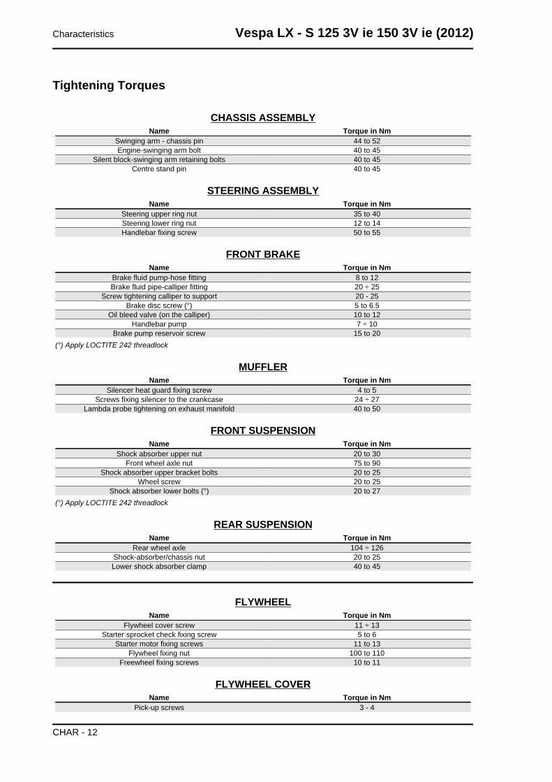
Tightening Torques
CHASSIS ASSEMBLYName Torque in Nm
Swinging arm - chassis pin 44 to 52Engine-swinging arm bolt 40 to 45
Silent block-swinging arm retaining bolts 40 to 45Centre stand pin 40 to 45
STEERING ASSEMBLYName Torque in Nm
Steering upper ring nut 35 to 40Steering lower ring nut 12 to 14Handlebar fixing screw 50 to 55
FRONT BRAKEName Torque in Nm
Brake fluid pump-hose fitting 8 to 12Brake fluid pipe-calliper fitting 20 ÷ 25
Screw tightening calliper to support 20 - 25Brake disc screw (°) 5 to 6.5
Oil bleed valve (on the calliper) 10 to 12Handlebar pump 7 ÷ 10
Brake pump reservoir screw 15 to 20(°) Apply LOCTITE 242 threadlock
MUFFLERName Torque in Nm
Silencer heat guard fixing screw 4 to 5Screws fixing silencer to the crankcase 24 ÷ 27
Lambda probe tightening on exhaust manifold 40 to 50
FRONT SUSPENSIONName Torque in Nm
Shock absorber upper nut 20 to 30Front wheel axle nut 75 to 90
Shock absorber upper bracket bolts 20 to 25Wheel screw 20 to 25
Shock absorber lower bolts (°) 20 to 27(°) Apply LOCTITE 242 threadlock
REAR SUSPENSIONName Torque in Nm
Rear wheel axle 104 ÷ 126Shock-absorber/chassis nut 20 to 25Lower shock absorber clamp 40 to 45
FLYWHEELName Torque in Nm
Flywheel cover screw 11 ÷ 13Starter sprocket check fixing screw 5 to 6
Starter motor fixing screws 11 to 13Flywheel fixing nut 100 to 110
Freewheel fixing screws 10 to 11
FLYWHEEL COVERName Torque in Nm
Pick-up screws 3 - 4
Characteristics Vespa LX - S 125 3V ie 150 3V ie (2012)
CHAR - 12
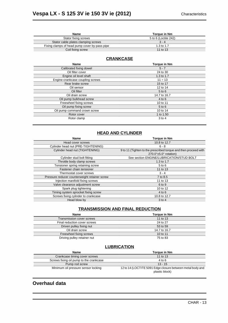
Name Torque in NmStator fixing screws 5 to 6 (Loctite 242)
Stator cable plates clamping screws 3 - 4Fixing clamps of head pump cover by-pass pipe 1.3 to 1.7
Coil fixing screw 11 to 13
CRANKCASEName Torque in Nm
Calibrated fixing dowel 5 - 7Oil filter cover 24 to 30
Engine oil level shaft 1.3 to 1.7Engine-crankcase coupling screws 11 ÷ 13
Rear brake screw 15 to 17Oil sensor 12 to 14
Oil filter 5 to 6Oil drain screw 14.7 to 16.7
Oil pump bulkhead screw 4 to 6Freewheel fixing screws 10 to 11
Oil pump fixing screw 5 to 6Oil pump command crown screw 10 to 14
Rotor cover 1 to 1.50Rotor clamp 3 to 4
HEAD AND CYLINDERName Torque in Nm
Head cover screws 10.8 to 12.7Cylinder head nut (PRE-TIGHTENING) 6 - 8
Cylinder head nut (TIGHTENING) 9 to 11 (Tighten to the prescribed torque and then proceed with270.0°±5.0° rotation)
Cylinder stud bolt fitting See section ENGINE/LUBRICATION/STUD BOLTThrottle body clamp screws 1.3 to 1.7
Tensioner spring retaining screw 5 to 6Fastener chain tensioner 11 to 13Thermostat cover screws 3 - 4
Pressure reducer counterweight retainer screw 7 to 8.5Injection manifold fixing screws 11 to 13
Valve clearance adjustment screw 6 to 9Spark plug tightening 10 to 12
Timing system sprocket fixing screw 4 to 6Screws fixing cylinder to crankcase 10.8 to 12.7
Head blow by 3 to 4
TRANSMISSION AND FINAL REDUCTIONName Torque in Nm
Transmission cover screws 11 to 13Final reduction cover screws 24 to 27
Driven pulley fixing nut 53 to 59Oil drain screw 14.7 to 16.7
Freewheel fixing screws 10 to 11Driving pulley retainer nut 75 to 83
LUBRICATIONName Torque in Nm
Crankcase timing cover screws 11 to 13Screws fixing oil pump to the crankcase 4 to 6
Pump rod screw 13 - 15Minimum oil pressure sensor locking 12 to 14 (LOCTITE 5091 Edge closure between metal body and
plastic block)
Overhaul data
Vespa LX - S 125 3V ie 150 3V ie (2012) Characteristics
CHAR - 13
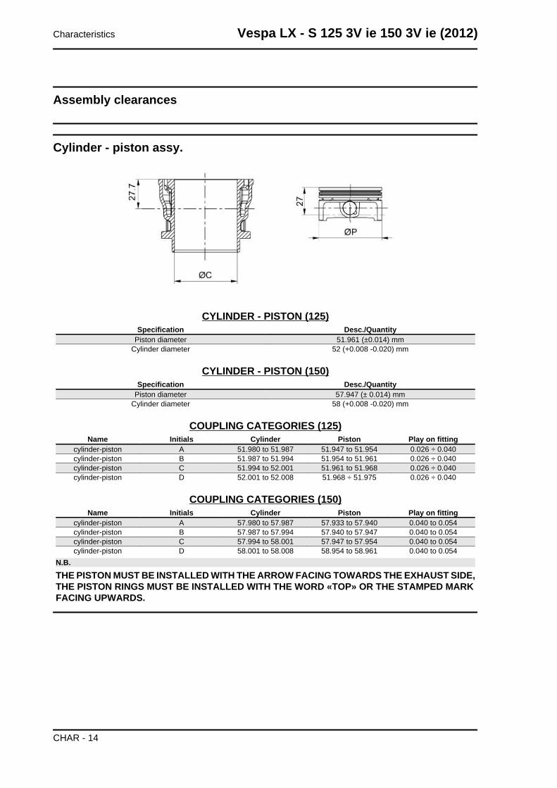
Assembly clearances
Cylinder - piston assy.
CYLINDER - PISTON (125)Specification Desc./Quantity
Piston diameter 51.961 (±0.014) mmCylinder diameter 52 (+0.008 -0.020) mm
CYLINDER - PISTON (150)Specification Desc./Quantity
Piston diameter 57.947 (± 0.014) mmCylinder diameter 58 (+0.008 -0.020) mm
COUPLING CATEGORIES (125)Name Initials Cylinder Piston Play on fitting
cylinder-piston A 51.980 to 51.987 51.947 to 51.954 0.026 ÷ 0.040cylinder-piston B 51.987 to 51.994 51.954 to 51.961 0.026 ÷ 0.040cylinder-piston C 51.994 to 52.001 51.961 to 51.968 0.026 ÷ 0.040cylinder-piston D 52.001 to 52.008 51.968 ÷ 51.975 0.026 ÷ 0.040
COUPLING CATEGORIES (150)Name Initials Cylinder Piston Play on fitting
cylinder-piston A 57.980 to 57.987 57.933 to 57.940 0.040 to 0.054cylinder-piston B 57.987 to 57.994 57.940 to 57.947 0.040 to 0.054cylinder-piston C 57.994 to 58.001 57.947 to 57.954 0.040 to 0.054cylinder-piston D 58.001 to 58.008 58.954 to 58.961 0.040 to 0.054
N.B.
THE PISTON MUST BE INSTALLED WITH THE ARROW FACING TOWARDS THE EXHAUST SIDE,THE PISTON RINGS MUST BE INSTALLED WITH THE WORD «TOP» OR THE STAMPED MARKFACING UPWARDS.
Characteristics Vespa LX - S 125 3V ie 150 3V ie (2012)
CHAR - 14
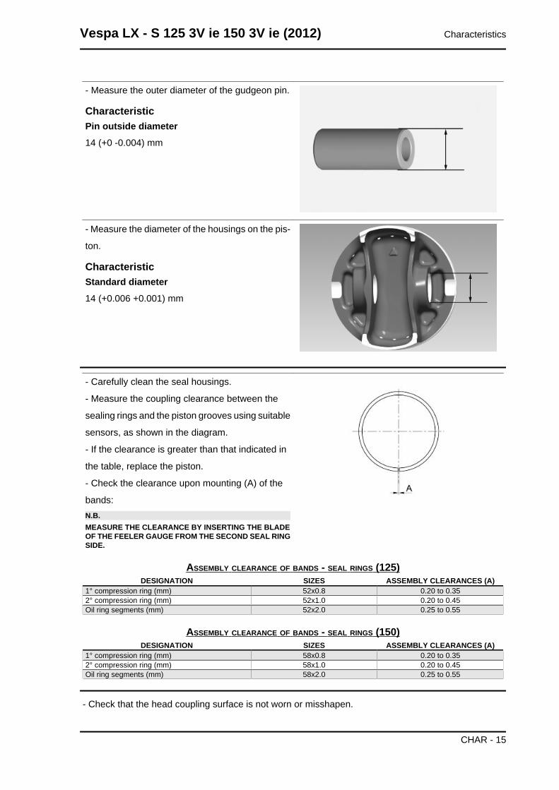
- Measure the outer diameter of the gudgeon pin.
CharacteristicPin outside diameter14 (+0 -0.004) mm
- Measure the diameter of the housings on the pis-
ton.
CharacteristicStandard diameter14 (+0.006 +0.001) mm
- Carefully clean the seal housings.
- Measure the coupling clearance between the
sealing rings and the piston grooves using suitable
sensors, as shown in the diagram.
- If the clearance is greater than that indicated in
the table, replace the piston.
- Check the clearance upon mounting (A) of the
bands:N.B.MEASURE THE CLEARANCE BY INSERTING THE BLADEOF THE FEELER GAUGE FROM THE SECOND SEAL RINGSIDE.
ASSEMBLY CLEARANCE OF BANDS - SEAL RINGS (125)DESIGNATION SIZES ASSEMBLY CLEARANCES (A)
1° compression ring (mm) 52x0.8 0.20 to 0.352° compression ring (mm) 52x1.0 0.20 to 0.45Oil ring segments (mm) 52x2.0 0.25 to 0.55
ASSEMBLY CLEARANCE OF BANDS - SEAL RINGS (150)DESIGNATION SIZES ASSEMBLY CLEARANCES (A)
1° compression ring (mm) 58x0.8 0.20 to 0.352° compression ring (mm) 58x1.0 0.20 to 0.45Oil ring segments (mm) 58x2.0 0.25 to 0.55
- Check that the head coupling surface is not worn or misshapen.
Vespa LX - S 125 3V ie 150 3V ie (2012) Characteristics
CHAR - 15
- Pistons and cylinders are classified according to diameter. The coupling is carried out in pairs (A-A,
B-B, C-C, D-D).
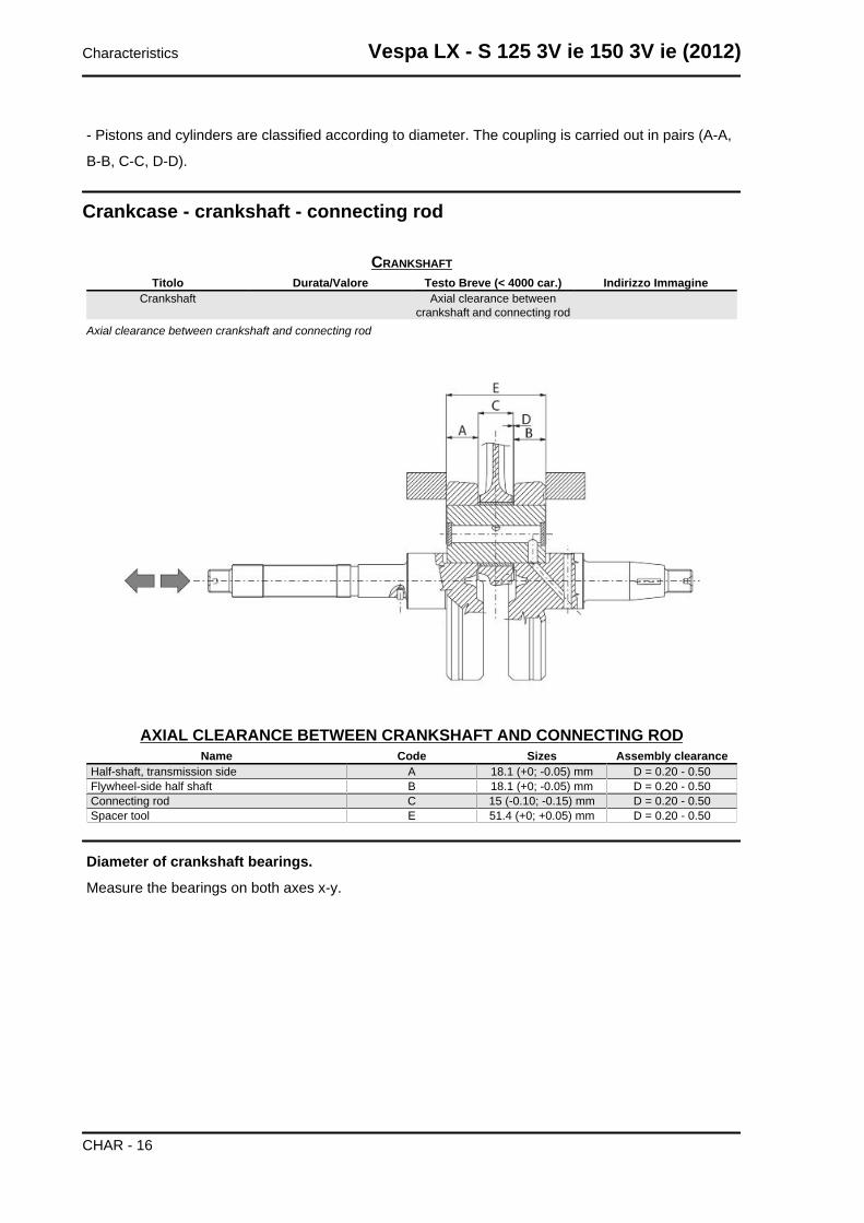
Crankcase - crankshaft - connecting rod
CRANKSHAFTTitolo Durata/Valore Testo Breve (< 4000 car.) Indirizzo Immagine
Crankshaft Axial clearance betweencrankshaft and connecting rod
Axial clearance between crankshaft and connecting rod
AXIAL CLEARANCE BETWEEN CRANKSHAFT AND CONNECTING RODName Code Sizes Assembly clearance
Half-shaft, transmission side A 18.1 (+0; -0.05) mm D = 0.20 - 0.50Flywheel-side half shaft B 18.1 (+0; -0.05) mm D = 0.20 - 0.50Connecting rod C 15 (-0.10; -0.15) mm D = 0.20 - 0.50Spacer tool E 51.4 (+0; +0.05) mm D = 0.20 - 0.50
Diameter of crankshaft bearings.
Measure the bearings on both axes x-y.
Characteristics Vespa LX - S 125 3V ie 150 3V ie (2012)
CHAR - 16
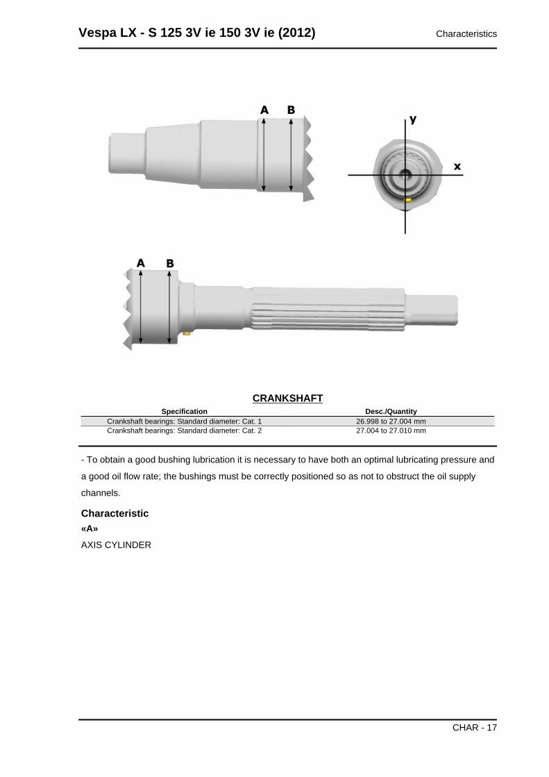
CRANKSHAFTSpecification Desc./Quantity
Crankshaft bearings: Standard diameter: Cat. 1 26.998 to 27.004 mmCrankshaft bearings: Standard diameter: Cat. 2 27.004 to 27.010 mm
- To obtain a good bushing lubrication it is necessary to have both an optimal lubricating pressure and
a good oil flow rate; the bushings must be correctly positioned so as not to obstruct the oil supply
channels.
Characteristic«A»
AXIS CYLINDER
Vespa LX - S 125 3V ie 150 3V ie (2012) Characteristics
CHAR - 17
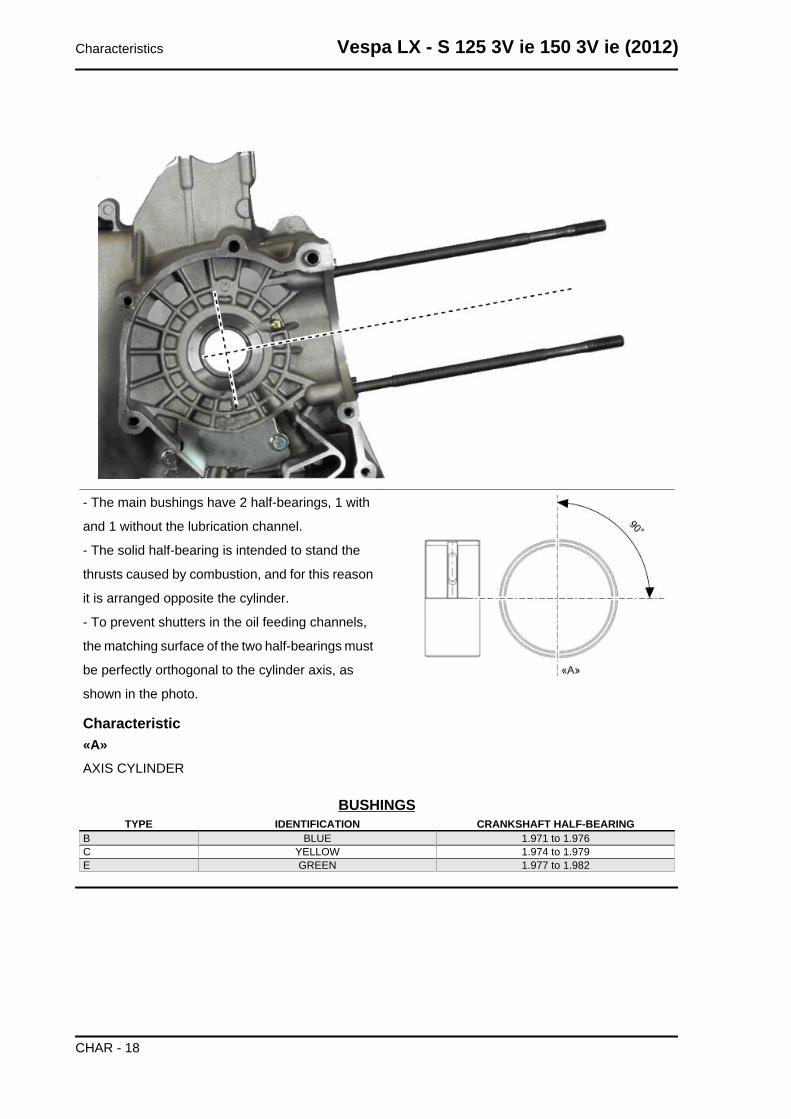
- The main bushings have 2 half-bearings, 1 with
and 1 without the lubrication channel.
- The solid half-bearing is intended to stand the
thrusts caused by combustion, and for this reason
it is arranged opposite the cylinder.
- To prevent shutters in the oil feeding channels,
the matching surface of the two half-bearings must
be perfectly orthogonal to the cylinder axis, as
shown in the photo.
Characteristic«A»AXIS CYLINDER
BUSHINGSTYPE IDENTIFICATION CRANKSHAFT HALF-BEARING
B BLUE 1.971 to 1.976C YELLOW 1.974 to 1.979E GREEN 1.977 to 1.982
Characteristics Vespa LX - S 125 3V ie 150 3V ie (2012)
CHAR - 18
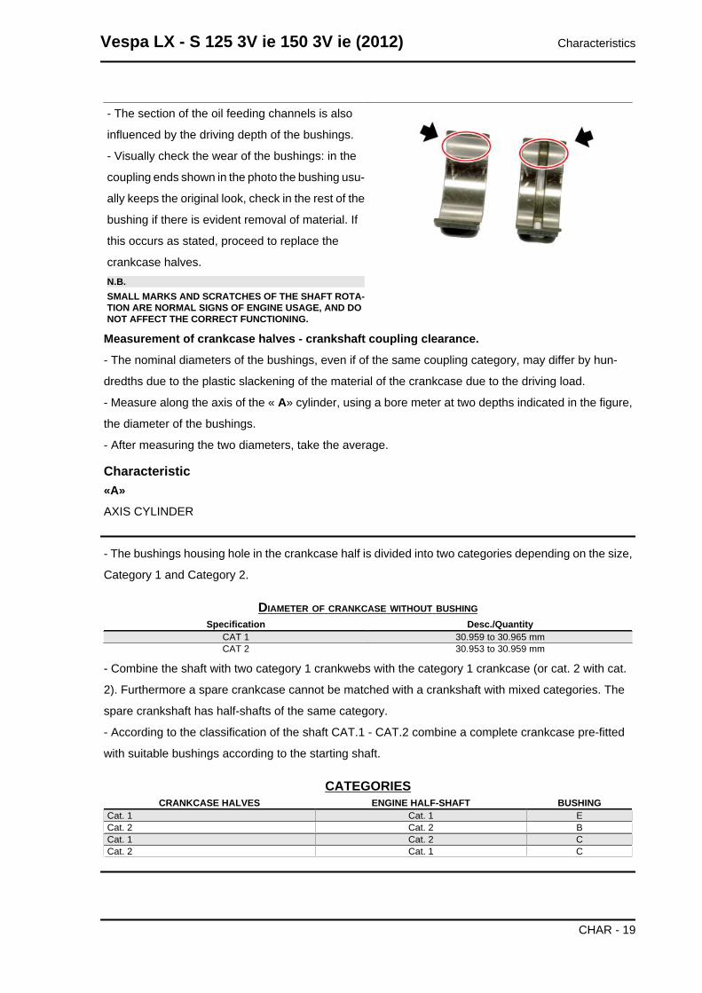
- The section of the oil feeding channels is also
influenced by the driving depth of the bushings.
- Visually check the wear of the bushings: in the
coupling ends shown in the photo the bushing usu-
ally keeps the original look, check in the rest of the
bushing if there is evident removal of material. If
this occurs as stated, proceed to replace the
crankcase halves.N.B.SMALL MARKS AND SCRATCHES OF THE SHAFT ROTA-TION ARE NORMAL SIGNS OF ENGINE USAGE, AND DONOT AFFECT THE CORRECT FUNCTIONING.
Measurement of crankcase halves - crankshaft coupling clearance.
- The nominal diameters of the bushings, even if of the same coupling category, may differ by hun-
dredths due to the plastic slackening of the material of the crankcase due to the driving load.
- Measure along the axis of the « A» cylinder, using a bore meter at two depths indicated in the figure,
the diameter of the bushings.
- After measuring the two diameters, take the average.
Characteristic«A»
AXIS CYLINDER
- The bushings housing hole in the crankcase half is divided into two categories depending on the size,
Category 1 and Category 2.
DIAMETER OF CRANKCASE WITHOUT BUSHINGSpecification Desc./Quantity
CAT 1 30.959 to 30.965 mmCAT 2 30.953 to 30.959 mm
- Combine the shaft with two category 1 crankwebs with the category 1 crankcase (or cat. 2 with cat.
2). Furthermore a spare crankcase cannot be matched with a crankshaft with mixed categories. The
spare crankshaft has half-shafts of the same category.
- According to the classification of the shaft CAT.1 - CAT.2 combine a complete crankcase pre-fitted
with suitable bushings according to the starting shaft.
CATEGORIESCRANKCASE HALVES ENGINE HALF-SHAFT BUSHING
Cat. 1 Cat. 1 ECat. 2 Cat. 2 BCat. 1 Cat. 2 CCat. 2 Cat. 1 C
Vespa LX - S 125 3V ie 150 3V ie (2012) Characteristics
CHAR - 19
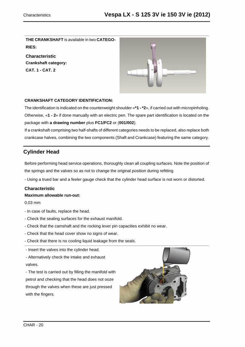
THE CRANKSHAFT is available in two CATEGO-
RIES:
CharacteristicCrankshaft category:CAT. 1 - CAT. 2
CRANKSHAFT CATEGORY IDENTIFICATION:
The identification is indicated on the counterweight shoulder «*1 - *2», if carried out with micropinholing.
Otherwise, «1 - 2» if done manually with an electric pen. The spare part identification is located on the
package with a drawing number plus FC1/FC2 or (001/002).
If a crankshaft comprising two half-shafts of different categories needs to be replaced, also replace both
crankcase halves, combining the two components (Shaft and Crankcase) featuring the same category.
Cylinder Head
Before performing head service operations, thoroughly clean all coupling surfaces. Note the position of
the springs and the valves so as not to change the original position during refitting
- Using a trued bar and a feeler gauge check that the cylinder head surface is not worn or distorted.
CharacteristicMaximum allowable run-out:
0.03 mm
- In case of faults, replace the head.
- Check the sealing surfaces for the exhaust manifold.
- Check that the camshaft and the rocking lever pin capacities exhibit no wear.
- Check that the head cover show no signs of wear.
- Check that there is no cooling liquid leakage from the seals.
- Insert the valves into the cylinder head.
- Alternatively check the intake and exhaust
valves.
- The test is carried out by filling the manifold with
petrol and checking that the head does not ooze
through the valves when these are just pressed
with the fingers.
Characteristics Vespa LX - S 125 3V ie 150 3V ie (2012)
CHAR - 20
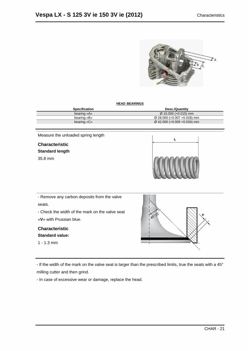
HEAD BEARINGSSpecification Desc./Quantitybearing «A» Ø 10.000 (+0.015) mmbearing «B» Ø 28.000 (+0.007 +0.028) mmbearing «C» Ø 42.000 (+0.009 +0.034) mm
Measure the unloaded spring length
CharacteristicStandard length35.8 mm
- Remove any carbon deposits from the valve
seats.
- Check the width of the mark on the valve seat
«V» with Prussian blue.
CharacteristicStandard value:1 - 1.3 mm
- If the width of the mark on the valve seat is larger than the prescribed limits, true the seats with a 45°
milling cutter and then grind.
- In case of excessive wear or damage, replace the head.
Vespa LX - S 125 3V ie 150 3V ie (2012) Characteristics
CHAR - 21
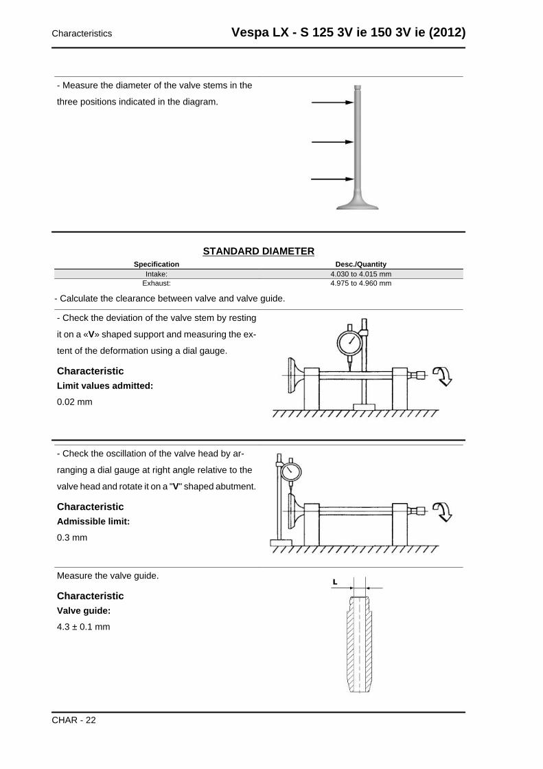
- Measure the diameter of the valve stems in the
three positions indicated in the diagram.
STANDARD DIAMETERSpecification Desc./Quantity
Intake: 4.030 to 4.015 mmExhaust: 4.975 to 4.960 mm
- Calculate the clearance between valve and valve guide.
- Check the deviation of the valve stem by resting
it on a «V» shaped support and measuring the ex-
tent of the deformation using a dial gauge.
CharacteristicLimit values admitted:0.02 mm
- Check the oscillation of the valve head by ar-
ranging a dial gauge at right angle relative to the
valve head and rotate it on a "V" shaped abutment.
CharacteristicAdmissible limit:0.3 mm
Measure the valve guide.
CharacteristicValve guide:4.3 ± 0.1 mm
Characteristics Vespa LX - S 125 3V ie 150 3V ie (2012)
CHAR - 22
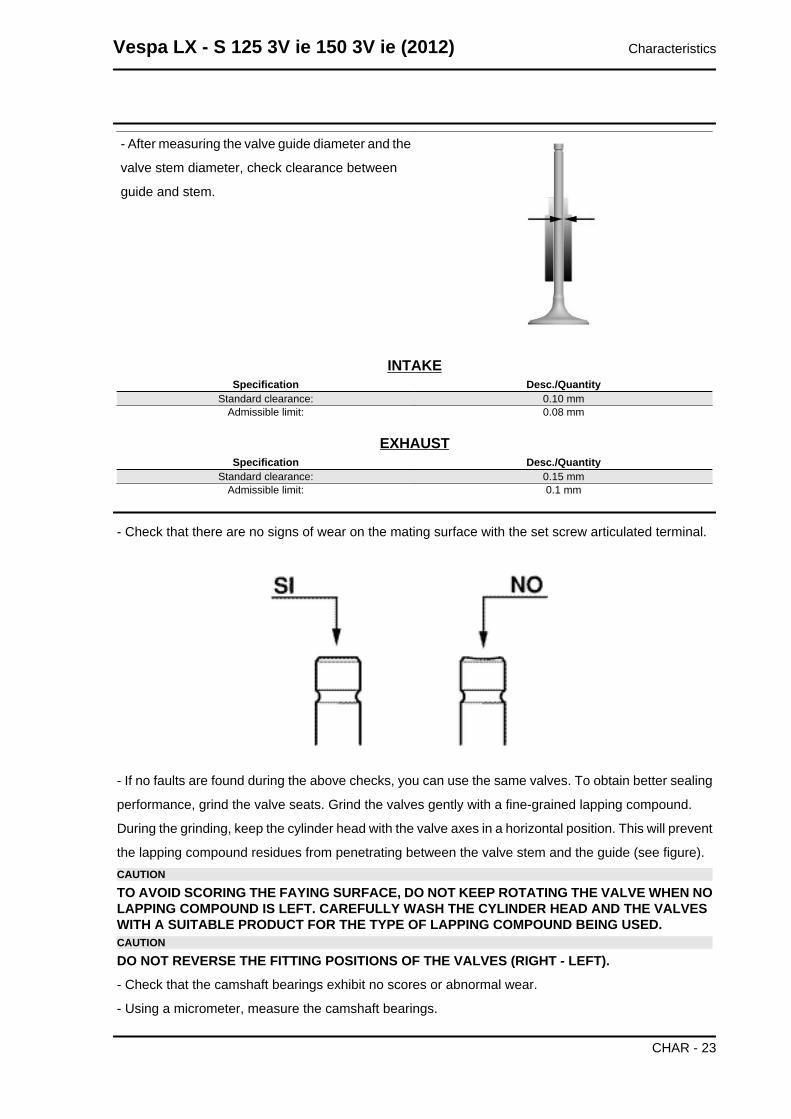
- After measuring the valve guide diameter and the
valve stem diameter, check clearance between
guide and stem.
INTAKESpecification Desc./Quantity
Standard clearance: 0.10 mmAdmissible limit: 0.08 mm
EXHAUSTSpecification Desc./Quantity
Standard clearance: 0.15 mmAdmissible limit: 0.1 mm
- Check that there are no signs of wear on the mating surface with the set screw articulated terminal.
- If no faults are found during the above checks, you can use the same valves. To obtain better sealing
performance, grind the valve seats. Grind the valves gently with a fine-grained lapping compound.
During the grinding, keep the cylinder head with the valve axes in a horizontal position. This will prevent
the lapping compound residues from penetrating between the valve stem and the guide (see figure).CAUTION
TO AVOID SCORING THE FAYING SURFACE, DO NOT KEEP ROTATING THE VALVE WHEN NOLAPPING COMPOUND IS LEFT. CAREFULLY WASH THE CYLINDER HEAD AND THE VALVESWITH A SUITABLE PRODUCT FOR THE TYPE OF LAPPING COMPOUND BEING USED.CAUTION
DO NOT REVERSE THE FITTING POSITIONS OF THE VALVES (RIGHT - LEFT).
- Check that the camshaft bearings exhibit no scores or abnormal wear.
- Using a micrometer, measure the camshaft bearings.
Vespa LX - S 125 3V ie 150 3V ie (2012) Characteristics
CHAR - 23
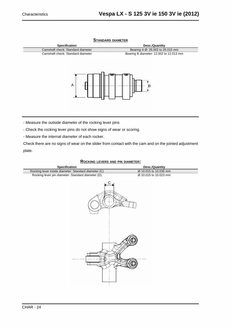
STANDARD DIAMETERSpecification Desc./Quantity
Camshaft check: Standard diameter Bearing A Ø: 25.002 to 25.015 mmCamshaft check: Standard diameter Bearing B diameter: 12.002 to 12.013 mm
- Measure the outside diameter of the rocking lever pins
- Check the rocking lever pins do not show signs of wear or scoring.
- Measure the internal diameter of each rocker.
Check there are no signs of wear on the slider from contact with the cam and on the jointed adjustment
plate.
ROCKING LEVERS AND PIN DIAMETER:Specification Desc./Quantity
Rocking lever inside diameter: Standard diameter (C) Ø 10.015 to 10.035 mmRocking lever pin diameter: Standard diameter (D) Ø 10.015 to 10.023 mm
Characteristics Vespa LX - S 125 3V ie 150 3V ie (2012)
CHAR - 24
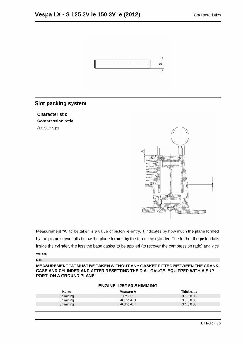
Slot packing system
CharacteristicCompression ratio(10.5±0.5):1
Measurement "A" to be taken is a value of piston re-entry, it indicates by how much the plane formed
by the piston crown falls below the plane formed by the top of the cylinder. The further the piston falls
inside the cylinder, the less the base gasket to be applied (to recover the compression ratio) and vice
versa.N.B.
MEASUREMENT "A" MUST BE TAKEN WITHOUT ANY GASKET FITTED BETWEEN THE CRANK-CASE AND CYLINDER AND AFTER RESETTING THE DIAL GAUGE, EQUIPPED WITH A SUP-PORT, ON A GROUND PLANE
ENGINE 125/150 SHIMMINGName Measure A Thickness
Shimming 0 to -0.1 0.8 ± 0.05Shimming -0.1 to -0.3 0.6 ± 0.05Shimming -0.3 to -0.4 0.4 ± 0.05
Vespa LX - S 125 3V ie 150 3V ie (2012) Characteristics
CHAR - 25
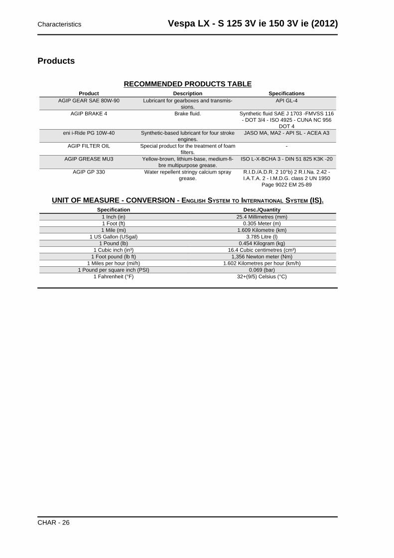
Products
RECOMMENDED PRODUCTS TABLEProduct Description Specifications
AGIP GEAR SAE 80W-90 Lubricant for gearboxes and transmis-sions.
API GL-4
AGIP BRAKE 4 Brake fluid. Synthetic fluid SAE J 1703 -FMVSS 116- DOT 3/4 - ISO 4925 - CUNA NC 956
DOT 4eni i-Ride PG 10W-40 Synthetic-based lubricant for four stroke
engines.JASO MA, MA2 - API SL - ACEA A3
AGIP FILTER OIL Special product for the treatment of foamfilters.
-
AGIP GREASE MU3 Yellow-brown, lithium-base, medium-fi-bre multipurpose grease.
ISO L-X-BCHA 3 - DIN 51 825 K3K -20
AGIP GP 330 Water repellent stringy calcium spraygrease.
R.I.D./A.D.R. 2 10°b) 2 R.I.Na. 2.42 -I.A.T.A. 2 - I.M.D.G. class 2 UN 1950
Page 9022 EM 25-89
UNIT OF MEASURE - CONVERSION - ENGLISH SYSTEM TO INTERNATIONAL SYSTEM (IS).Specification Desc./Quantity
1 Inch (in) 25.4 Millimetres (mm)1 Foot (ft) 0.305 Meter (m)1 Mile (mi) 1.609 Kilometre (km)
1 US Gallon (USgal) 3.785 Litre (l)1 Pound (lb) 0.454 Kilogram (kg)
1 Cubic inch (in³) 16.4 Cubic centimetres (cm³)1 Foot pound (lb ft) 1,356 Newton meter (Nm)
1 Miles per hour (mi/h) 1.602 Kilometres per hour (km/h)1 Pound per square inch (PSI) 0.069 (bar)
1 Fahrenheit (°F) 32+(9/5) Celsius (°C)
Characteristics Vespa LX - S 125 3V ie 150 3V ie (2012)
CHAR - 26
INDEX OF TOPICS
TOOLING TOOL
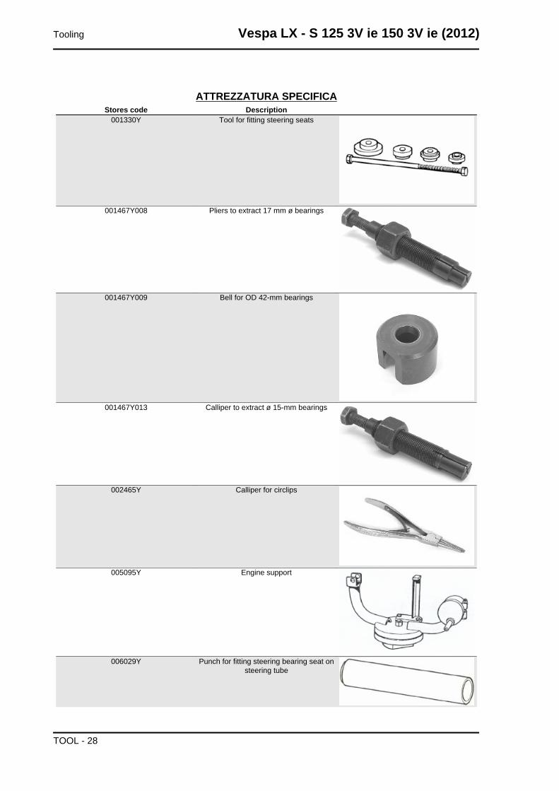
ATTREZZATURA SPECIFICAStores code Description
001330Y Tool for fitting steering seats
001467Y008 Pliers to extract 17 mm ø bearings
001467Y009 Bell for OD 42-mm bearings
001467Y013 Calliper to extract ø 15-mm bearings
002465Y Calliper for circlips
005095Y Engine support
006029Y Punch for fitting steering bearing seat onsteering tube
Tooling Vespa LX - S 125 3V ie 150 3V ie (2012)
TOOL - 28
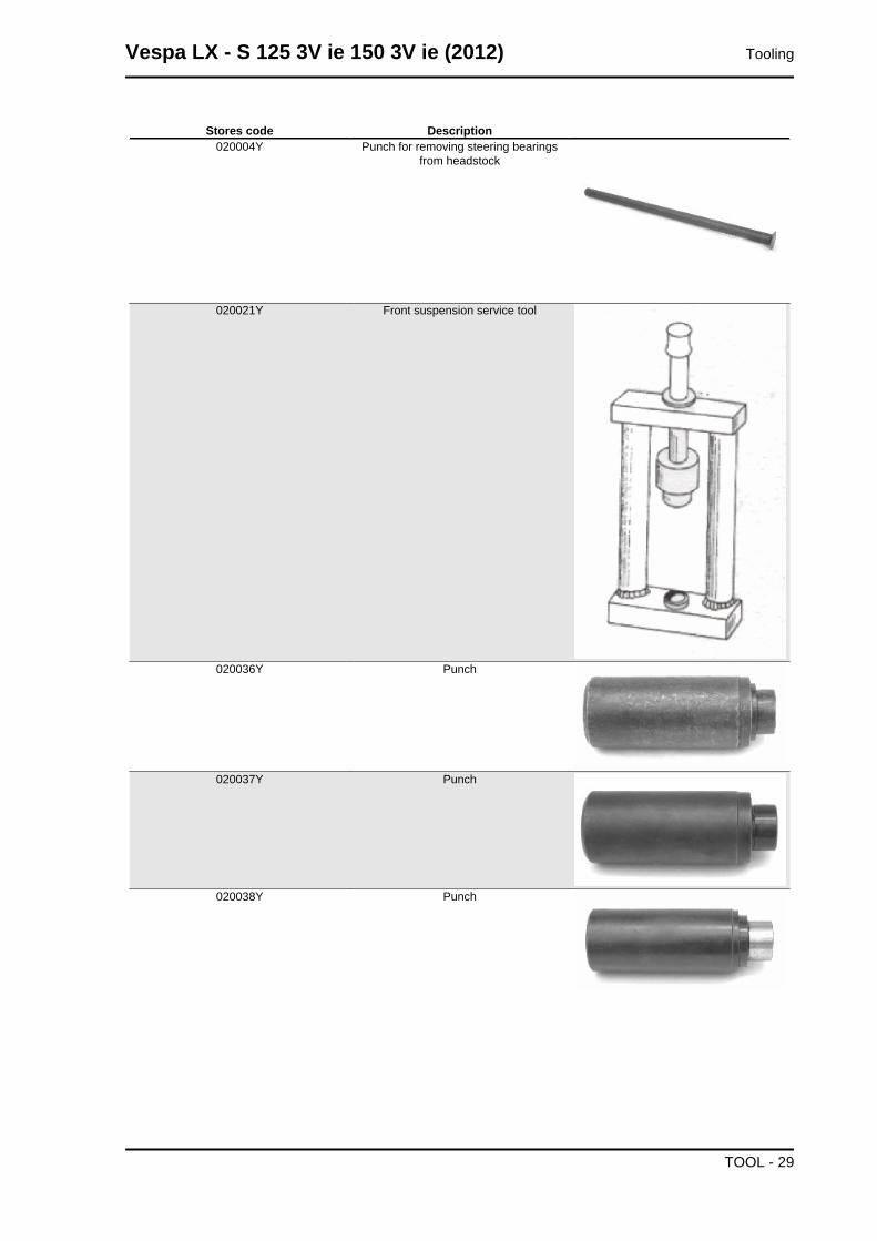
Stores code Description020004Y Punch for removing steering bearings
from headstock
020021Y Front suspension service tool
020036Y Punch
020037Y Punch
020038Y Punch
Vespa LX - S 125 3V ie 150 3V ie (2012) Tooling
TOOL - 29
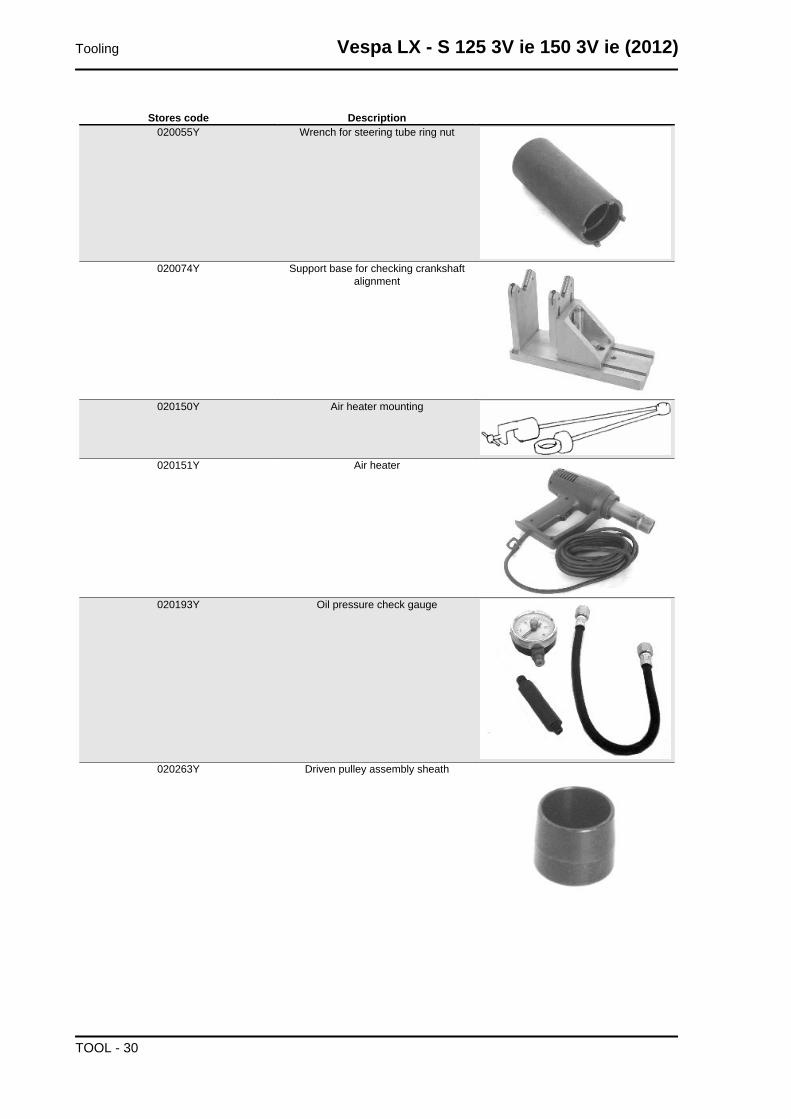
Stores code Description020055Y Wrench for steering tube ring nut
020074Y Support base for checking crankshaftalignment
020150Y Air heater mounting
020151Y Air heater
020193Y Oil pressure check gauge
020263Y Driven pulley assembly sheath
Tooling Vespa LX - S 125 3V ie 150 3V ie (2012)
TOOL - 30
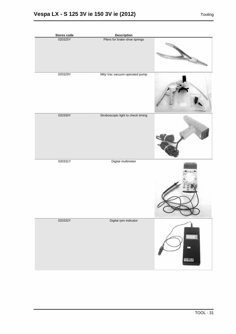
Stores code Description020325Y Pliers for brake-shoe springs
020329Y Mity-Vac vacuum-operated pump
020330Y Stroboscopic light to check timing
020331Y Digital multimeter
020332Y Digital rpm indicator
Vespa LX - S 125 3V ie 150 3V ie (2012) Tooling
TOOL - 31
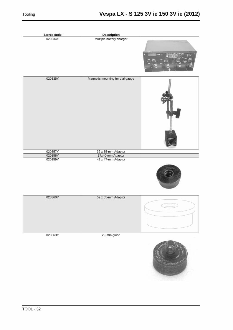
Stores code Description020334Y Multiple battery charger
020335Y Magnetic mounting for dial gauge
020357Y 32 x 35-mm Adaptor020358Y 37x40-mm Adaptor020359Y 42 x 47-mm Adaptor
020360Y 52 x 55-mm Adaptor
020363Y 20-mm guide
Tooling Vespa LX - S 125 3V ie 150 3V ie (2012)
TOOL - 32
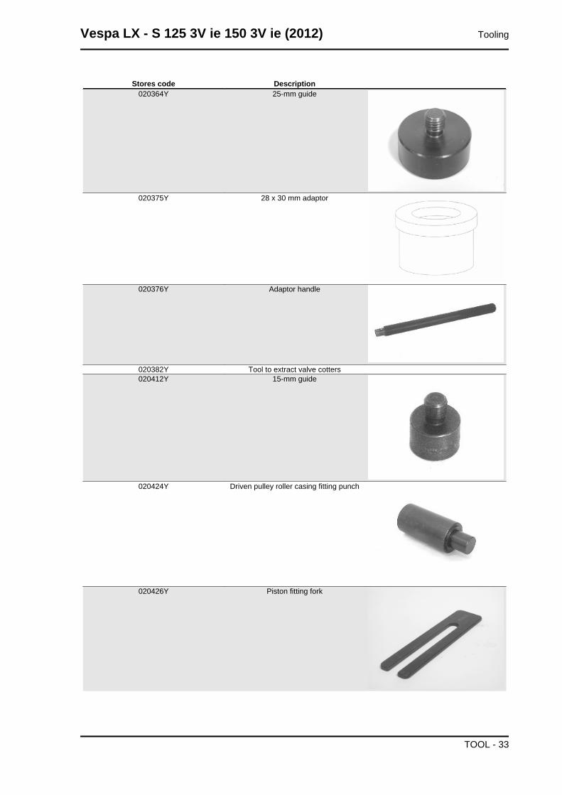
Stores code Description020364Y 25-mm guide
020375Y 28 x 30 mm adaptor
020376Y Adaptor handle
020382Y Tool to extract valve cotters020412Y 15-mm guide
020424Y Driven pulley roller casing fitting punch
020426Y Piston fitting fork
Vespa LX - S 125 3V ie 150 3V ie (2012) Tooling
TOOL - 33

Stores code Description020427Y Piston assembly band
020431Y Valve oil seal extractor
020434Y Oil pressure check fitting
020441Y 26 x 28 mm adaptor
020444Y011 adapter ring
020444Y009 wrench 46 x 55
Tooling Vespa LX - S 125 3V ie 150 3V ie (2012)
TOOL - 34
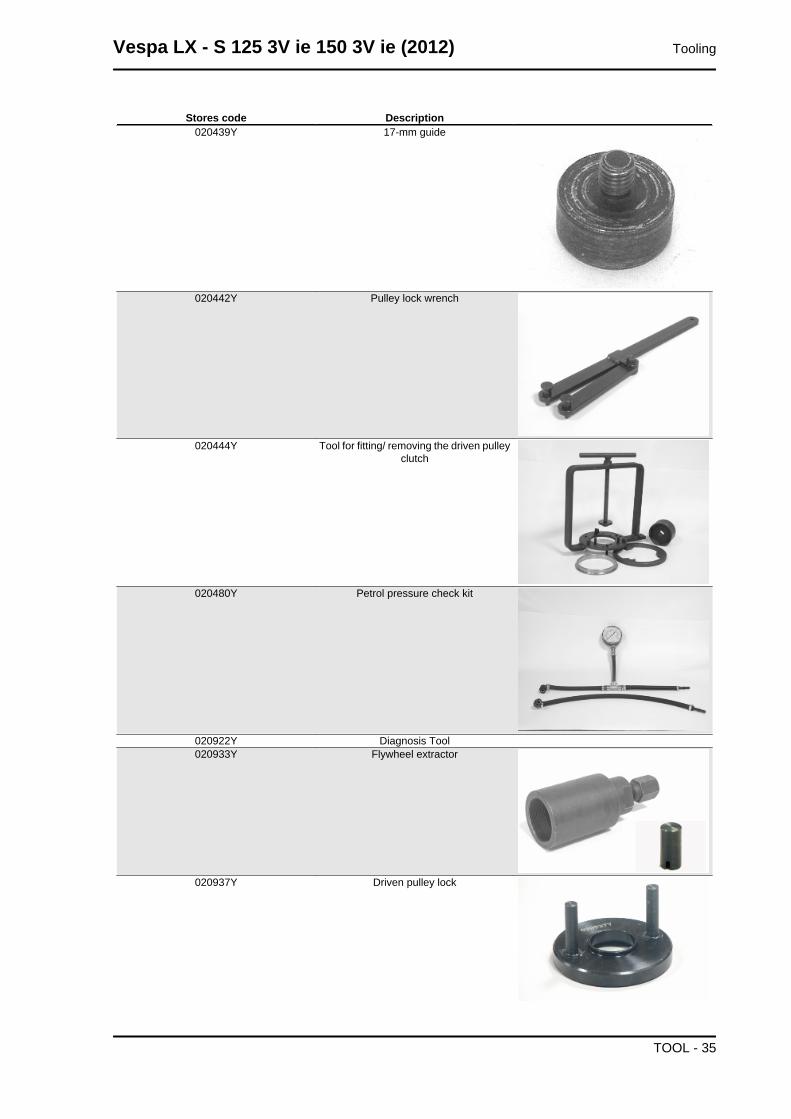
Stores code Description020439Y 17-mm guide
020442Y Pulley lock wrench
020444Y Tool for fitting/ removing the driven pulleyclutch
020480Y Petrol pressure check kit
020922Y Diagnosis Tool020933Y Flywheel extractor
020937Y Driven pulley lock
Vespa LX - S 125 3V ie 150 3V ie (2012) Tooling
TOOL - 35
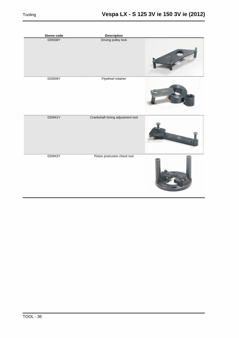
Stores code Description020938Y Driving pulley lock
020939Y Flywheel retainer
020941Y Crankshaft timing adjustment tool
020942Y Piston protrusion check tool
Tooling Vespa LX - S 125 3V ie 150 3V ie (2012)
TOOL - 36

INDEX OF TOPICS
MAINTENANCE MAIN
Maintenance chart
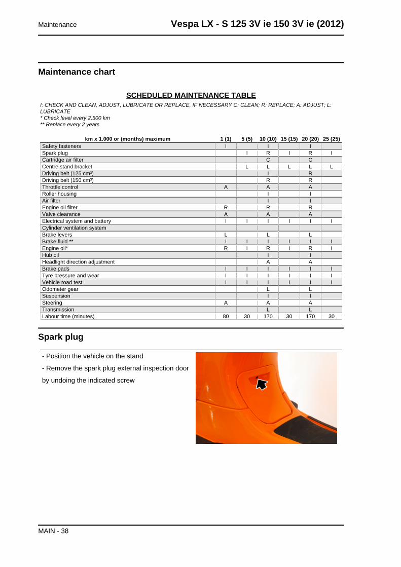
SCHEDULED MAINTENANCE TABLEI: CHECK AND CLEAN, ADJUST, LUBRICATE OR REPLACE, IF NECESSARY C: CLEAN; R: REPLACE; A: ADJUST; L:LUBRICATE* Check level every 2,500 km** Replace every 2 years
km x 1.000 or (months) maximum 1 (1) 5 (5) 10 (10) 15 (15) 20 (20) 25 (25)Safety fasteners I I ISpark plug I R I R ICartridge air filter C CCentre stand bracket L L L L LDriving belt (125 cm³) I RDriving belt (150 cm³) R RThrottle control A A ARoller housing I IAir filter I IEngine oil filter R R RValve clearance A A AElectrical system and battery I I I I I ICylinder ventilation systemBrake levers L L LBrake fluid ** I I I I I IEngine oil* R I R I R IHub oil I IHeadlight direction adjustment A ABrake pads I I I I I ITyre pressure and wear I I I I I IVehicle road test I I I I I IOdometer gear L LSuspension I ISteering A A ATransmission L LLabour time (minutes) 80 30 170 30 170 30
Spark plug
- Position the vehicle on the stand
- Remove the spark plug external inspection door
by undoing the indicated screw
Maintenance Vespa LX - S 125 3V ie 150 3V ie (2012)
MAIN - 38
- Disconnect the spark plug H.V. cable cap.
- Unscrew the spark plug using the wrench sup-
plied.
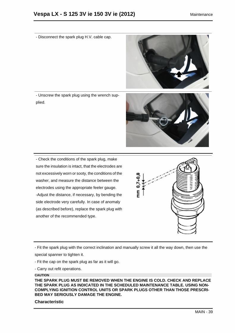
- Check the conditions of the spark plug, make
sure the insulation is intact, that the electrodes are
not excessively worn or sooty, the conditions of the
washer, and measure the distance between the
electrodes using the appropriate feeler gauge.
-Adjust the distance, if necessary, by bending the
side electrode very carefully. In case of anomaly
(as described before), replace the spark plug with
another of the recommended type.
- Fit the spark plug with the correct inclination and manually screw it all the way down, then use the
special spanner to tighten it.
- Fit the cap on the spark plug as far as it will go.
- Carry out refit operations.CAUTIONTHE SPARK PLUG MUST BE REMOVED WHEN THE ENGINE IS COLD. CHECK AND REPLACETHE SPARK PLUG AS INDICATED IN THE SCHEDULED MAINTENANCE TABLE. USING NON-COMPLYING IGNITION CONTROL UNITS OR SPARK PLUGS OTHER THAN THOSE PRESCRI-BED MAY SERIOUSLY DAMAGE THE ENGINE.
Characteristic
Vespa LX - S 125 3V ie 150 3V ie (2012) Maintenance
MAIN - 39
Electrode gap
0.7 to 0.8 mm
Spark plug
NGK CR8EB
Locking torques (N*m)Spark plug tightening 10 to 12
Hub oil
Check
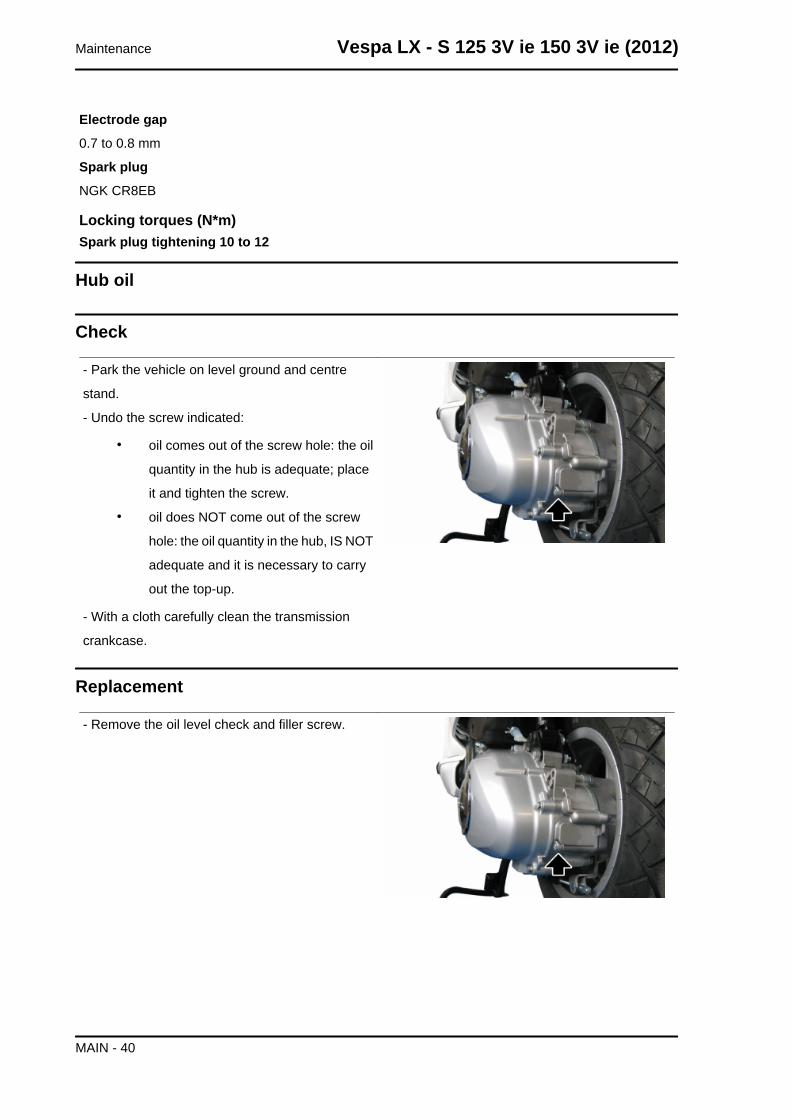
- Park the vehicle on level ground and centre
stand.
- Undo the screw indicated:
• oil comes out of the screw hole: the oil
quantity in the hub is adequate; place
it and tighten the screw.
• oil does NOT come out of the screw
hole: the oil quantity in the hub, IS NOT
adequate and it is necessary to carry
out the top-up.
- With a cloth carefully clean the transmission
crankcase.
Replacement
- Remove the oil level check and filler screw.
Maintenance Vespa LX - S 125 3V ie 150 3V ie (2012)
MAIN - 40
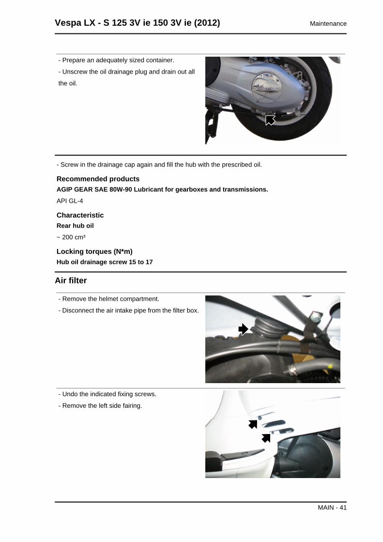
- Prepare an adequately sized container.
- Unscrew the oil drainage plug and drain out all
the oil.
- Screw in the drainage cap again and fill the hub with the prescribed oil.
Recommended productsAGIP GEAR SAE 80W-90 Lubricant for gearboxes and transmissions.
API GL-4
CharacteristicRear hub oil
~ 200 cm³
Locking torques (N*m)Hub oil drainage screw 15 to 17
Air filter
- Remove the helmet compartment.
- Disconnect the air intake pipe from the filter box.
- Undo the indicated fixing screws.
- Remove the left side fairing.
Vespa LX - S 125 3V ie 150 3V ie (2012) Maintenance
MAIN - 41
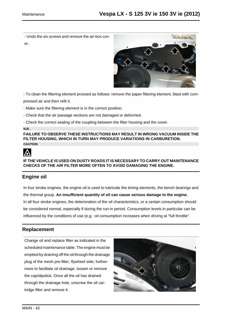
- Undo the six screws and remove the air-box cov-
er.
- To clean the filtering element proceed as follows: remove the paper filtering element, blast with com-
pressed air and then refit it.
- Make sure the filtering element is in the correct position.
- Check that the air passage sections are not damaged or deformed.
- Check the correct sealing of the coupling between the filter housing and the cover.N.B.
FAILURE TO OBSERVE THESE INSTRUCTIONS MAY RESULT IN WRONG VACUUM INSIDE THEFILTER HOUSING, WHICH IN TURN MAY PRODUCE VARIATIONS IN CARBURETION.CAUTION
IF THE VEHICLE IS USED ON DUSTY ROADS IT IS NECESSARY TO CARRY OUT MAINTENANCECHECKS OF THE AIR FILTER MORE OFTEN TO AVOID DAMAGING THE ENGINE.
Engine oil
In four stroke engines, the engine oil is used to lubricate the timing elements, the bench bearings and
the thermal group. An insufficient quantity of oil can cause serious damage to the engine.
In all four stroke engines, the deterioration of the oil characteristics, or a certain consumption should
be considered normal, especially if during the run-in period. Consumption levels in particular can be
influenced by the conditions of use (e.g.: oil consumption increases when driving at "full throttle".
Replacement
Change oil and replace filter as indicated in the
scheduled maintenance table. The engine must be
emptied by draining off the oil through the drainage
plug of the mesh pre-filter, flywheel side; further-
more to facilitate oil drainage, loosen or remove
the cap/dipstick. Once all the oil has drained
through the drainage hole, unscrew the oil car-
tridge filter and remove it.
Maintenance Vespa LX - S 125 3V ie 150 3V ie (2012)
MAIN - 42
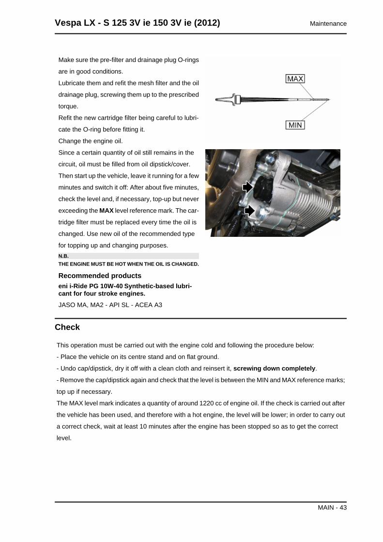
Make sure the pre-filter and drainage plug O-rings
are in good conditions.
Lubricate them and refit the mesh filter and the oil
drainage plug, screwing them up to the prescribed
torque.
Refit the new cartridge filter being careful to lubri-
cate the O-ring before fitting it.
Change the engine oil.
Since a certain quantity of oil still remains in the
circuit, oil must be filled from oil dipstick/cover.
Then start up the vehicle, leave it running for a few
minutes and switch it off: After about five minutes,
check the level and, if necessary, top-up but never
exceeding the MAX level reference mark. The car-
tridge filter must be replaced every time the oil is
changed. Use new oil of the recommended type
for topping up and changing purposes.N.B.THE ENGINE MUST BE HOT WHEN THE OIL IS CHANGED.
Recommended productseni i-Ride PG 10W-40 Synthetic-based lubri-cant for four stroke engines.JASO MA, MA2 - API SL - ACEA A3
Check
This operation must be carried out with the engine cold and following the procedure below:
- Place the vehicle on its centre stand and on flat ground.
- Undo cap/dipstick, dry it off with a clean cloth and reinsert it, screwing down completely.
- Remove the cap/dipstick again and check that the level is between the MIN and MAX reference marks;
top up if necessary.
The MAX level mark indicates a quantity of around 1220 cc of engine oil. If the check is carried out after
the vehicle has been used, and therefore with a hot engine, the level will be lower; in order to carry out
a correct check, wait at least 10 minutes after the engine has been stopped so as to get the correct
level.
Vespa LX - S 125 3V ie 150 3V ie (2012) Maintenance
MAIN - 43
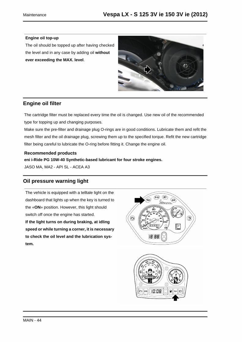
Engine oil top-up
The oil should be topped up after having checked
the level and in any case by adding oil without
ever exceeding the MAX. level.
Engine oil filter
The cartridge filter must be replaced every time the oil is changed. Use new oil of the recommended
type for topping up and changing purposes.
Make sure the pre-filter and drainage plug O-rings are in good conditions. Lubricate them and refit the
mesh filter and the oil drainage plug, screwing them up to the specified torque. Refit the new cartridge
filter being careful to lubricate the O-ring before fitting it. Change the engine oil.
Recommended productseni i-Ride PG 10W-40 Synthetic-based lubricant for four stroke engines.
JASO MA, MA2 - API SL - ACEA A3
Oil pressure warning light
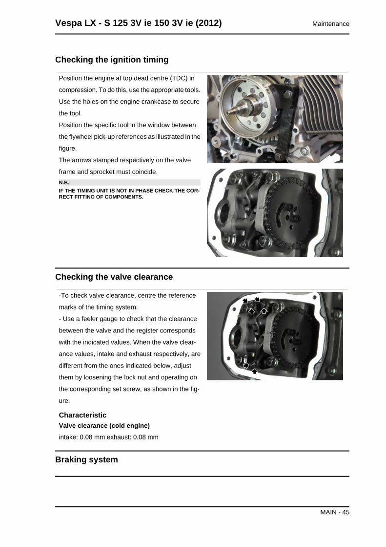
The vehicle is equipped with a telltale light on the
dashboard that lights up when the key is turned to
the «ON» position. However, this light should
switch off once the engine has started.
If the light turns on during braking, at idling
speed or while turning a corner, it is necessary
to check the oil level and the lubrication sys-
tem.
Maintenance Vespa LX - S 125 3V ie 150 3V ie (2012)
MAIN - 44
Checking the ignition timing
Position the engine at top dead centre (TDC) in
compression. To do this, use the appropriate tools.
Use the holes on the engine crankcase to secure
the tool.
Position the specific tool in the window between
the flywheel pick-up references as illustrated in the
figure.
The arrows stamped respectively on the valve
frame and sprocket must coincide.N.B.IF THE TIMING UNIT IS NOT IN PHASE CHECK THE COR-RECT FITTING OF COMPONENTS.
Checking the valve clearance
-To check valve clearance, centre the reference
marks of the timing system.
- Use a feeler gauge to check that the clearance
between the valve and the register corresponds
with the indicated values. When the valve clear-
ance values, intake and exhaust respectively, are
different from the ones indicated below, adjust
them by loosening the lock nut and operating on
the corresponding set screw, as shown in the fig-
ure.
CharacteristicValve clearance (cold engine)intake: 0.08 mm exhaust: 0.08 mm
Braking system
Vespa LX - S 125 3V ie 150 3V ie (2012) Maintenance
MAIN - 45
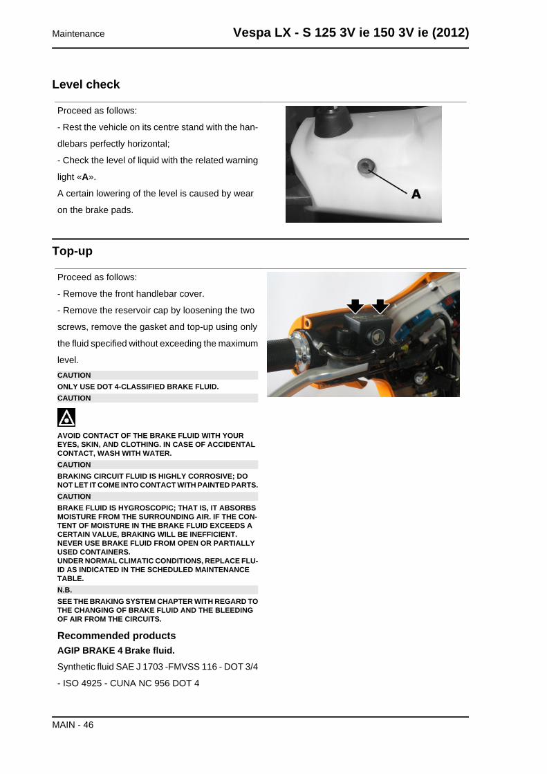
Level check
Proceed as follows:
- Rest the vehicle on its centre stand with the han-
dlebars perfectly horizontal;
- Check the level of liquid with the related warning
light «A».
A certain lowering of the level is caused by wear
on the brake pads.
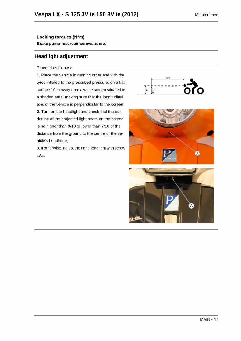
Top-up
Proceed as follows:
- Remove the front handlebar cover.
- Remove the reservoir cap by loosening the two
screws, remove the gasket and top-up using only
the fluid specified without exceeding the maximum
level.CAUTIONONLY USE DOT 4-CLASSIFIED BRAKE FLUID.CAUTION
AVOID CONTACT OF THE BRAKE FLUID WITH YOUREYES, SKIN, AND CLOTHING. IN CASE OF ACCIDENTALCONTACT, WASH WITH WATER.CAUTIONBRAKING CIRCUIT FLUID IS HIGHLY CORROSIVE; DONOT LET IT COME INTO CONTACT WITH PAINTED PARTS.CAUTIONBRAKE FLUID IS HYGROSCOPIC; THAT IS, IT ABSORBSMOISTURE FROM THE SURROUNDING AIR. IF THE CON-TENT OF MOISTURE IN THE BRAKE FLUID EXCEEDS ACERTAIN VALUE, BRAKING WILL BE INEFFICIENT.NEVER USE BRAKE FLUID FROM OPEN OR PARTIALLYUSED CONTAINERS.UNDER NORMAL CLIMATIC CONDITIONS, REPLACE FLU-ID AS INDICATED IN THE SCHEDULED MAINTENANCETABLE.N.B.SEE THE BRAKING SYSTEM CHAPTER WITH REGARD TOTHE CHANGING OF BRAKE FLUID AND THE BLEEDINGOF AIR FROM THE CIRCUITS.
Recommended productsAGIP BRAKE 4 Brake fluid.Synthetic fluid SAE J 1703 -FMVSS 116 - DOT 3/4
- ISO 4925 - CUNA NC 956 DOT 4
Maintenance Vespa LX - S 125 3V ie 150 3V ie (2012)
MAIN - 46
Locking torques (N*m)Brake pump reservoir screws 15 to 20
Headlight adjustment
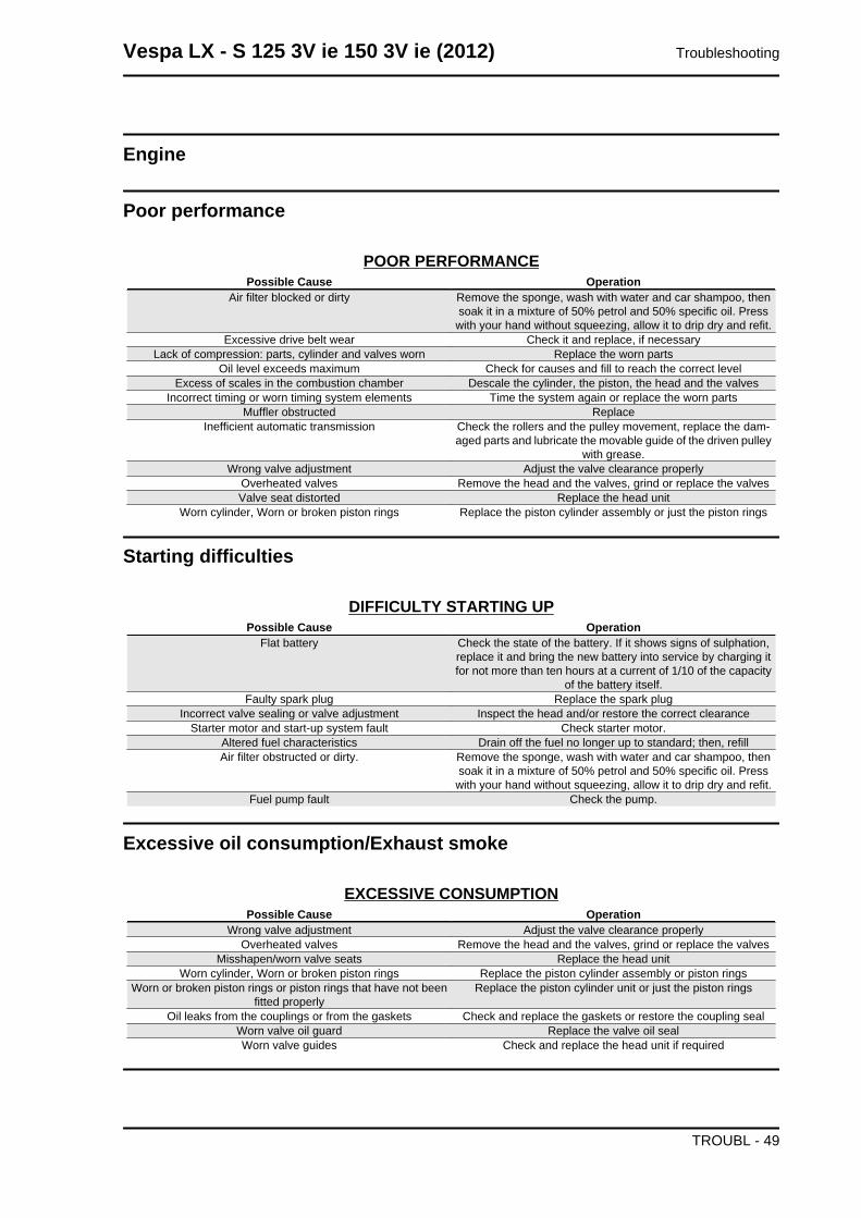
Proceed as follows:
1. Place the vehicle in running order and with the
tyres inflated to the prescribed pressure, on a flat
surface 10 m away from a white screen situated in
a shaded area, making sure that the longitudinal
axis of the vehicle is perpendicular to the screen;
2. Turn on the headlight and check that the bor-
derline of the projected light beam on the screen
is no higher than 9/10 or lower than 7/10 of the
distance from the ground to the centre of the ve-
hicle's headlamp;
3. If otherwise, adjust the right headlight with screw
«A».
Vespa LX - S 125 3V ie 150 3V ie (2012) Maintenance
MAIN - 47
INDEX OF TOPICS
TROUBLESHOOTING TROUBL
Engine
Poor performance
POOR PERFORMANCEPossible Cause Operation
Air filter blocked or dirty Remove the sponge, wash with water and car shampoo, thensoak it in a mixture of 50% petrol and 50% specific oil. Presswith your hand without squeezing, allow it to drip dry and refit.
Excessive drive belt wear Check it and replace, if necessaryLack of compression: parts, cylinder and valves worn Replace the worn parts
Oil level exceeds maximum Check for causes and fill to reach the correct levelExcess of scales in the combustion chamber Descale the cylinder, the piston, the head and the valves
Incorrect timing or worn timing system elements Time the system again or replace the worn partsMuffler obstructed Replace
Inefficient automatic transmission Check the rollers and the pulley movement, replace the dam-aged parts and lubricate the movable guide of the driven pulley
with grease.Wrong valve adjustment Adjust the valve clearance properly
Overheated valves Remove the head and the valves, grind or replace the valvesValve seat distorted Replace the head unit
Worn cylinder, Worn or broken piston rings Replace the piston cylinder assembly or just the piston rings
Starting difficulties
DIFFICULTY STARTING UPPossible Cause Operation
Flat battery Check the state of the battery. If it shows signs of sulphation,replace it and bring the new battery into service by charging itfor not more than ten hours at a current of 1/10 of the capacity
of the battery itself.Faulty spark plug Replace the spark plug
Incorrect valve sealing or valve adjustment Inspect the head and/or restore the correct clearanceStarter motor and start-up system fault Check starter motor.
Altered fuel characteristics Drain off the fuel no longer up to standard; then, refillAir filter obstructed or dirty. Remove the sponge, wash with water and car shampoo, then
soak it in a mixture of 50% petrol and 50% specific oil. Presswith your hand without squeezing, allow it to drip dry and refit.
Fuel pump fault Check the pump.
Excessive oil consumption/Exhaust smoke
EXCESSIVE CONSUMPTIONPossible Cause Operation
Wrong valve adjustment Adjust the valve clearance properlyOverheated valves Remove the head and the valves, grind or replace the valves
Misshapen/worn valve seats Replace the head unitWorn cylinder, Worn or broken piston rings Replace the piston cylinder assembly or piston rings
Worn or broken piston rings or piston rings that have not beenfitted properly
Replace the piston cylinder unit or just the piston rings
Oil leaks from the couplings or from the gaskets Check and replace the gaskets or restore the coupling sealWorn valve oil guard Replace the valve oil sealWorn valve guides Check and replace the head unit if required
Vespa LX - S 125 3V ie 150 3V ie (2012) Troubleshooting
TROUBL - 49
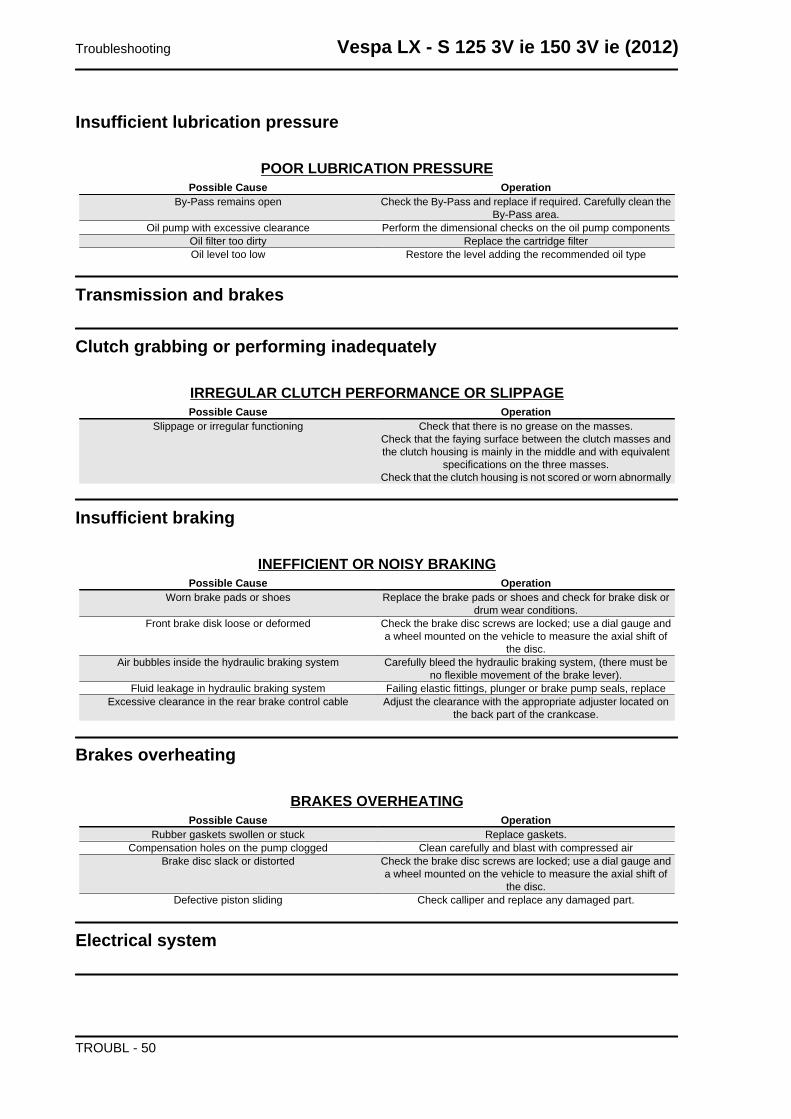
Insufficient lubrication pressure
POOR LUBRICATION PRESSUREPossible Cause Operation
By-Pass remains open Check the By-Pass and replace if required. Carefully clean theBy-Pass area.
Oil pump with excessive clearance Perform the dimensional checks on the oil pump componentsOil filter too dirty Replace the cartridge filterOil level too low Restore the level adding the recommended oil type
Transmission and brakes
Clutch grabbing or performing inadequately
IRREGULAR CLUTCH PERFORMANCE OR SLIPPAGEPossible Cause Operation
Slippage or irregular functioning Check that there is no grease on the masses.Check that the faying surface between the clutch masses andthe clutch housing is mainly in the middle and with equivalent
specifications on the three masses.Check that the clutch housing is not scored or worn abnormally
Insufficient braking
INEFFICIENT OR NOISY BRAKINGPossible Cause Operation
Worn brake pads or shoes Replace the brake pads or shoes and check for brake disk ordrum wear conditions.
Front brake disk loose or deformed Check the brake disc screws are locked; use a dial gauge anda wheel mounted on the vehicle to measure the axial shift of
the disc.Air bubbles inside the hydraulic braking system Carefully bleed the hydraulic braking system, (there must be
no flexible movement of the brake lever).Fluid leakage in hydraulic braking system Failing elastic fittings, plunger or brake pump seals, replace
Excessive clearance in the rear brake control cable Adjust the clearance with the appropriate adjuster located onthe back part of the crankcase.
Brakes overheating
BRAKES OVERHEATINGPossible Cause Operation
Rubber gaskets swollen or stuck Replace gaskets.Compensation holes on the pump clogged Clean carefully and blast with compressed air
Brake disc slack or distorted Check the brake disc screws are locked; use a dial gauge anda wheel mounted on the vehicle to measure the axial shift of
the disc.Defective piston sliding Check calliper and replace any damaged part.
Electrical system
Troubleshooting Vespa LX - S 125 3V ie 150 3V ie (2012)
TROUBL - 50
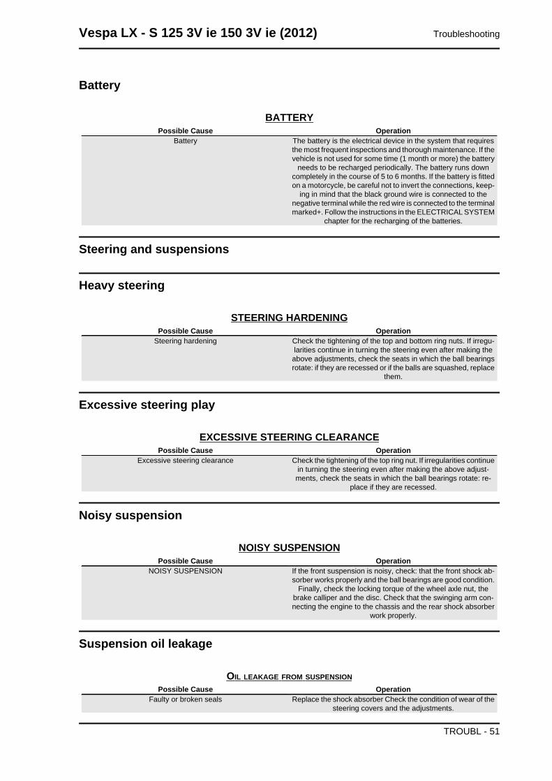
Battery
BATTERYPossible Cause Operation
Battery The battery is the electrical device in the system that requiresthe most frequent inspections and thorough maintenance. If thevehicle is not used for some time (1 month or more) the battery
needs to be recharged periodically. The battery runs downcompletely in the course of 5 to 6 months. If the battery is fittedon a motorcycle, be careful not to invert the connections, keep-
ing in mind that the black ground wire is connected to thenegative terminal while the red wire is connected to the terminalmarked+. Follow the instructions in the ELECTRICAL SYSTEM
chapter for the recharging of the batteries.
Steering and suspensions
Heavy steering
STEERING HARDENINGPossible Cause Operation
Steering hardening Check the tightening of the top and bottom ring nuts. If irregu-larities continue in turning the steering even after making theabove adjustments, check the seats in which the ball bearingsrotate: if they are recessed or if the balls are squashed, replace
them.
Excessive steering play
EXCESSIVE STEERING CLEARANCEPossible Cause Operation
Excessive steering clearance Check the tightening of the top ring nut. If irregularities continuein turning the steering even after making the above adjust-ments, check the seats in which the ball bearings rotate: re-
place if they are recessed.
Noisy suspension
NOISY SUSPENSIONPossible Cause Operation
NOISY SUSPENSION If the front suspension is noisy, check: that the front shock ab-sorber works properly and the ball bearings are good condition.
Finally, check the locking torque of the wheel axle nut, thebrake calliper and the disc. Check that the swinging arm con-necting the engine to the chassis and the rear shock absorber
work properly.
Suspension oil leakage
OIL LEAKAGE FROM SUSPENSIONPossible Cause Operation
Faulty or broken seals Replace the shock absorber Check the condition of wear of thesteering covers and the adjustments.
Vespa LX - S 125 3V ie 150 3V ie (2012) Troubleshooting
TROUBL - 51
Troubleshooting Vespa LX - S 125 3V ie 150 3V ie (2012)
TROUBL - 52
INDEX OF TOPICS
ELECTRICAL SYSTEM ELE SYS
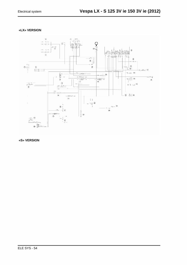
«LX» VERSION
«S» VERSION
Electrical system Vespa LX - S 125 3V ie 150 3V ie (2012)
ELE SYS - 54
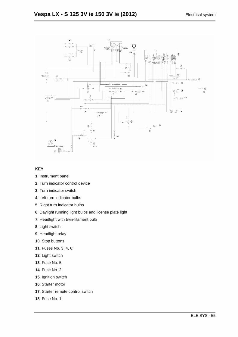
KEY
1. Instrument panel
2. Turn indicator control device
3. Turn indicator switch
4. Left turn indicator bulbs
5. Right turn indicator bulbs
6. Daylight running light bulbs and license plate light
7. Headlight with twin-filament bulb
8. Light switch
9. Headlight relay
10. Stop buttons
11. Fuses No. 3, 4, 6;
12. Light switch
13. Fuse No. 5
14. Fuse No. 2
15. Ignition switch
16. Starter motor
17. Starter remote control switch
18. Fuse No. 1
Vespa LX - S 125 3V ie 150 3V ie (2012) Electrical system
ELE SYS - 55
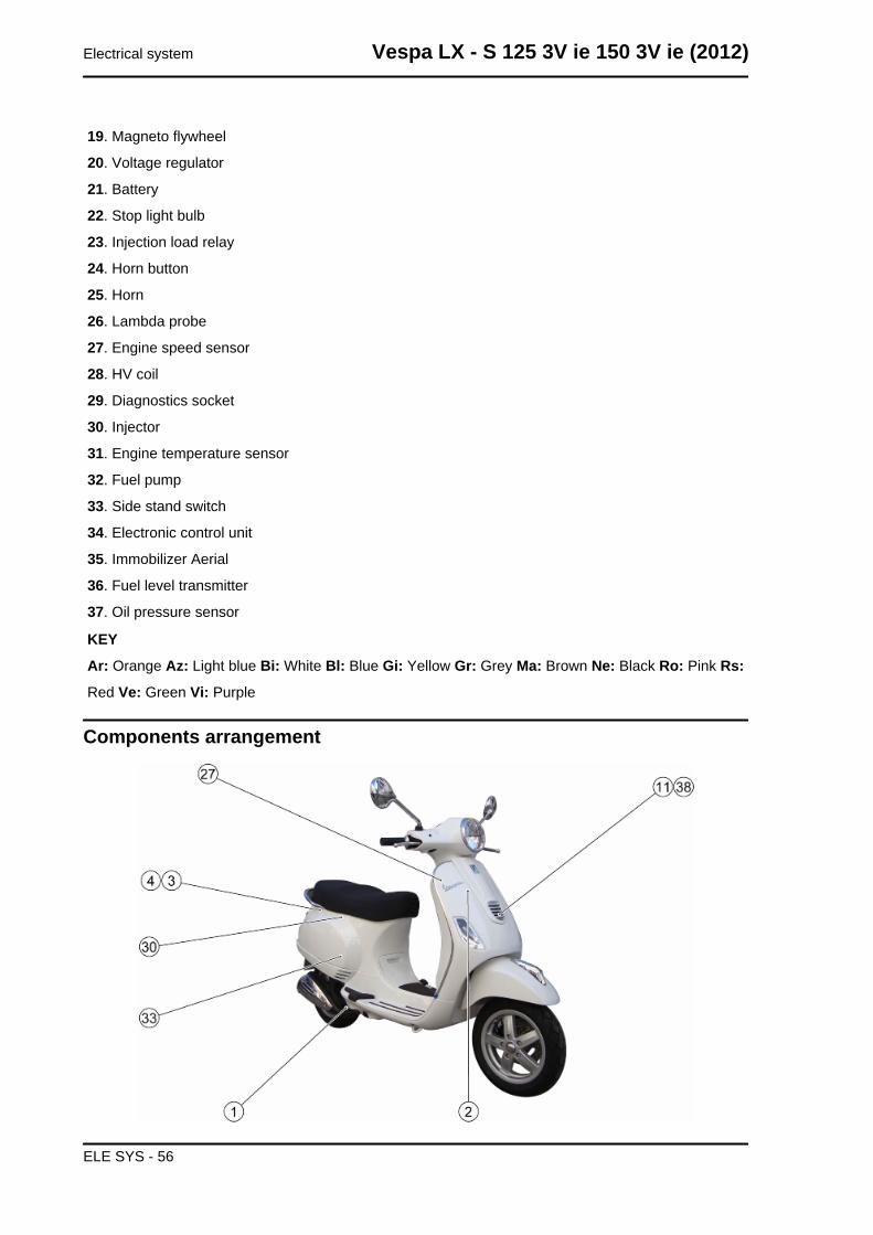
19. Magneto flywheel
20. Voltage regulator
21. Battery
22. Stop light bulb
23. Injection load relay
24. Horn button
25. Horn
26. Lambda probe
27. Engine speed sensor
28. HV coil
29. Diagnostics socket
30. Injector
31. Engine temperature sensor
32. Fuel pump
33. Side stand switch
34. Electronic control unit
35. Immobilizer Aerial
36. Fuel level transmitter
37. Oil pressure sensor
KEY
Ar: Orange Az: Light blue Bi: White Bl: Blue Gi: Yellow Gr: Grey Ma: Brown Ne: Black Ro: Pink Rs:
Red Ve: Green Vi: Purple
Components arrangement
Electrical system Vespa LX - S 125 3V ie 150 3V ie (2012)
ELE SYS - 56
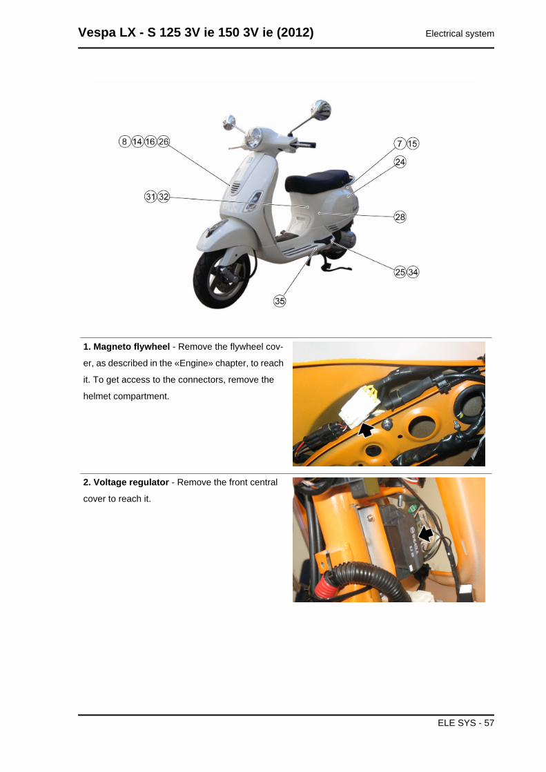
1. Magneto flywheel - Remove the flywheel cov-
er, as described in the «Engine» chapter, to reach
it. To get access to the connectors, remove the
helmet compartment.
2. Voltage regulator - Remove the front central
cover to reach it.
Vespa LX - S 125 3V ie 150 3V ie (2012) Electrical system
ELE SYS - 57
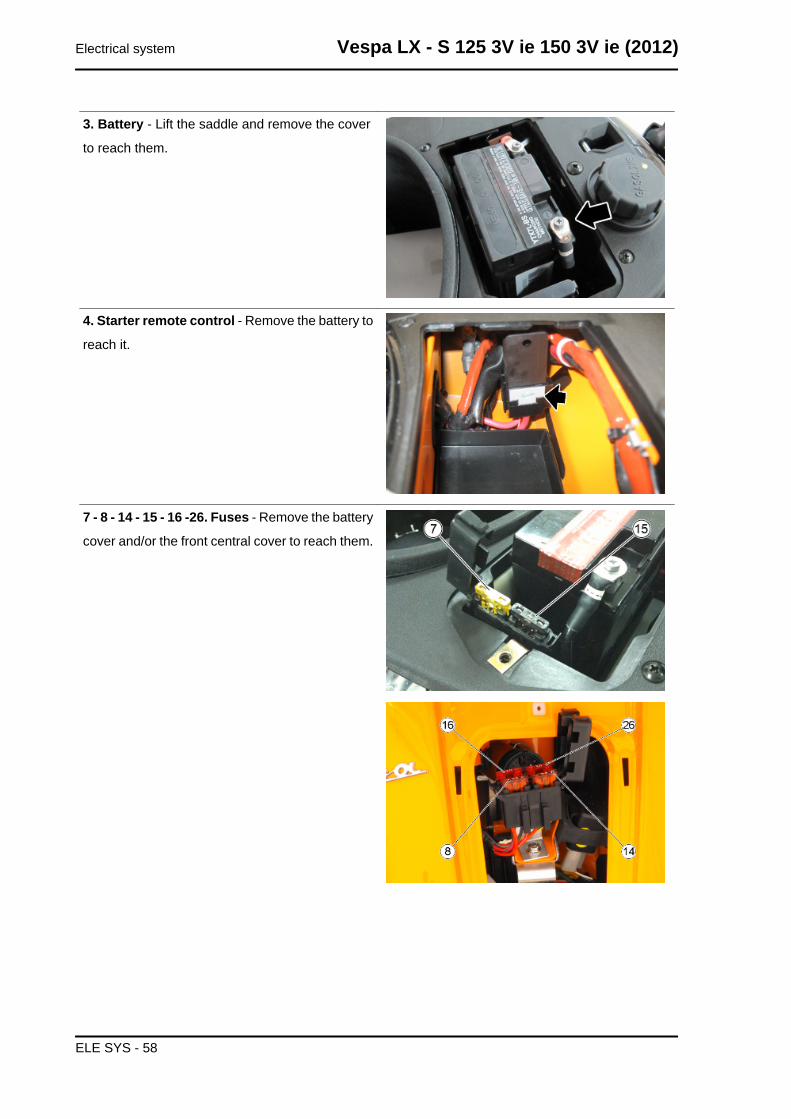
3. Battery - Lift the saddle and remove the cover
to reach them.
4. Starter remote control - Remove the battery to
reach it.
7 - 8 - 14 - 15 - 16 -26. Fuses - Remove the battery
cover and/or the front central cover to reach them.
Electrical system Vespa LX - S 125 3V ie 150 3V ie (2012)
ELE SYS - 58
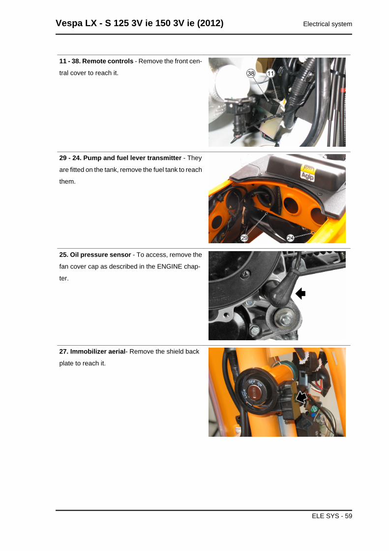
11 - 38. Remote controls - Remove the front cen-
tral cover to reach it.
29 - 24. Pump and fuel lever transmitter - They
are fitted on the tank, remove the fuel tank to reach
them.
25. Oil pressure sensor - To access, remove the
fan cover cap as described in the ENGINE chap-
ter.
27. Immobilizer aerial- Remove the shield back
plate to reach it.
Vespa LX - S 125 3V ie 150 3V ie (2012) Electrical system
ELE SYS - 59
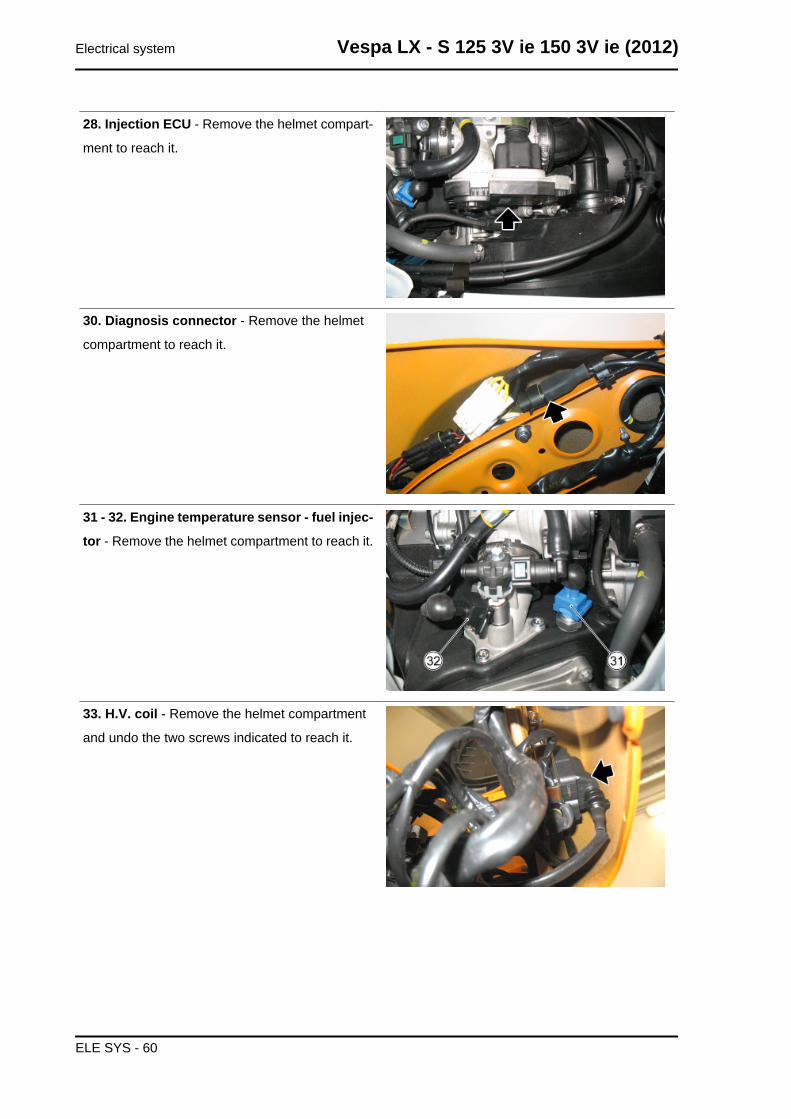
28. Injection ECU - Remove the helmet compart-
ment to reach it.
30. Diagnosis connector - Remove the helmet
compartment to reach it.
31 - 32. Engine temperature sensor - fuel injec-
tor - Remove the helmet compartment to reach it.
33. H.V. coil - Remove the helmet compartment
and undo the two screws indicated to reach it.
Electrical system Vespa LX - S 125 3V ie 150 3V ie (2012)
ELE SYS - 60
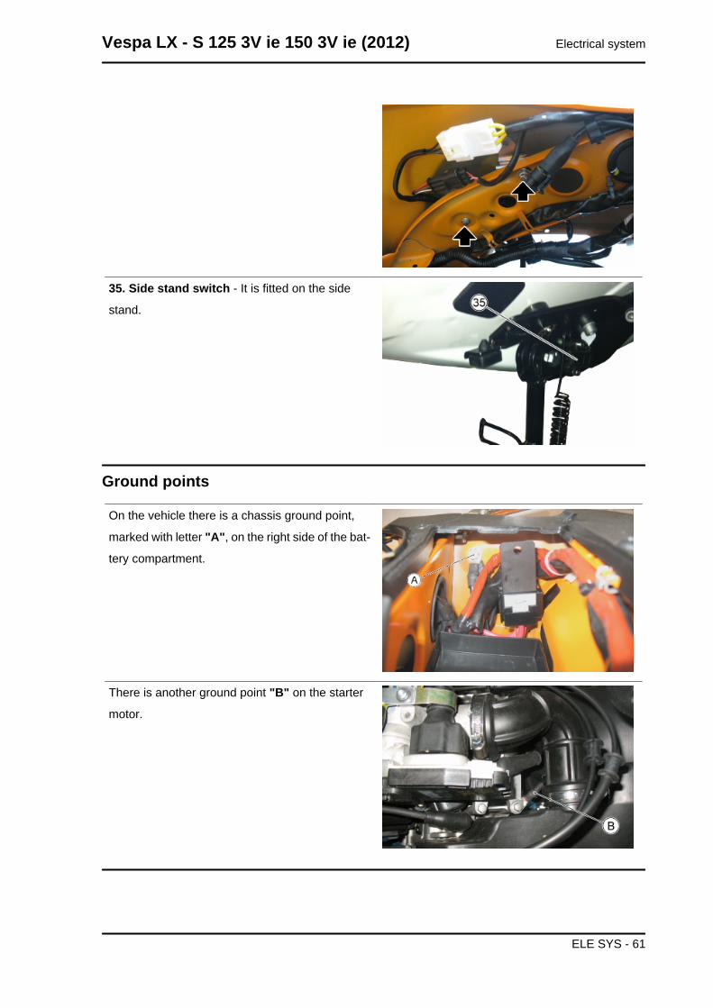
35. Side stand switch - It is fitted on the side
stand.
Ground points
On the vehicle there is a chassis ground point,
marked with letter "A", on the right side of the bat-
tery compartment.
There is another ground point "B" on the starter
motor.
Vespa LX - S 125 3V ie 150 3V ie (2012) Electrical system
ELE SYS - 61
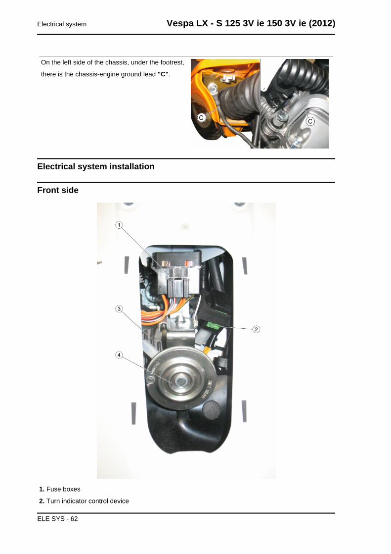
On the left side of the chassis, under the footrest,
there is the chassis-engine ground lead "C".
Electrical system installation
Front side
1. Fuse boxes
2. Turn indicator control device
Electrical system Vespa LX - S 125 3V ie 150 3V ie (2012)
ELE SYS - 62
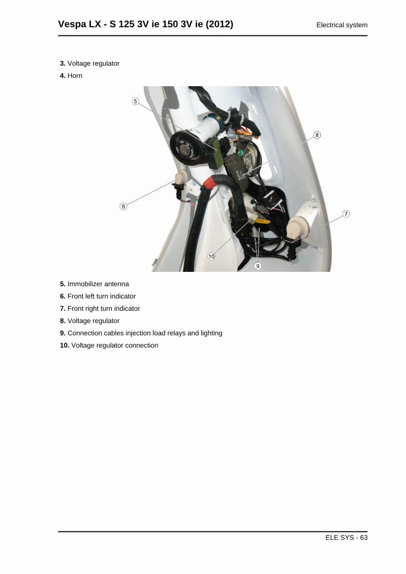
3. Voltage regulator
4. Horn
5. Immobilizer antenna
6. Front left turn indicator
7. Front right turn indicator
8. Voltage regulator
9. Connection cables injection load relays and lighting
10. Voltage regulator connection
Vespa LX - S 125 3V ie 150 3V ie (2012) Electrical system
ELE SYS - 63
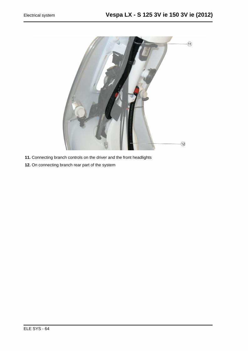
11. Connecting branch controls on the driver and the front headlights
12. On connecting branch rear part of the system
Electrical system Vespa LX - S 125 3V ie 150 3V ie (2012)
ELE SYS - 64
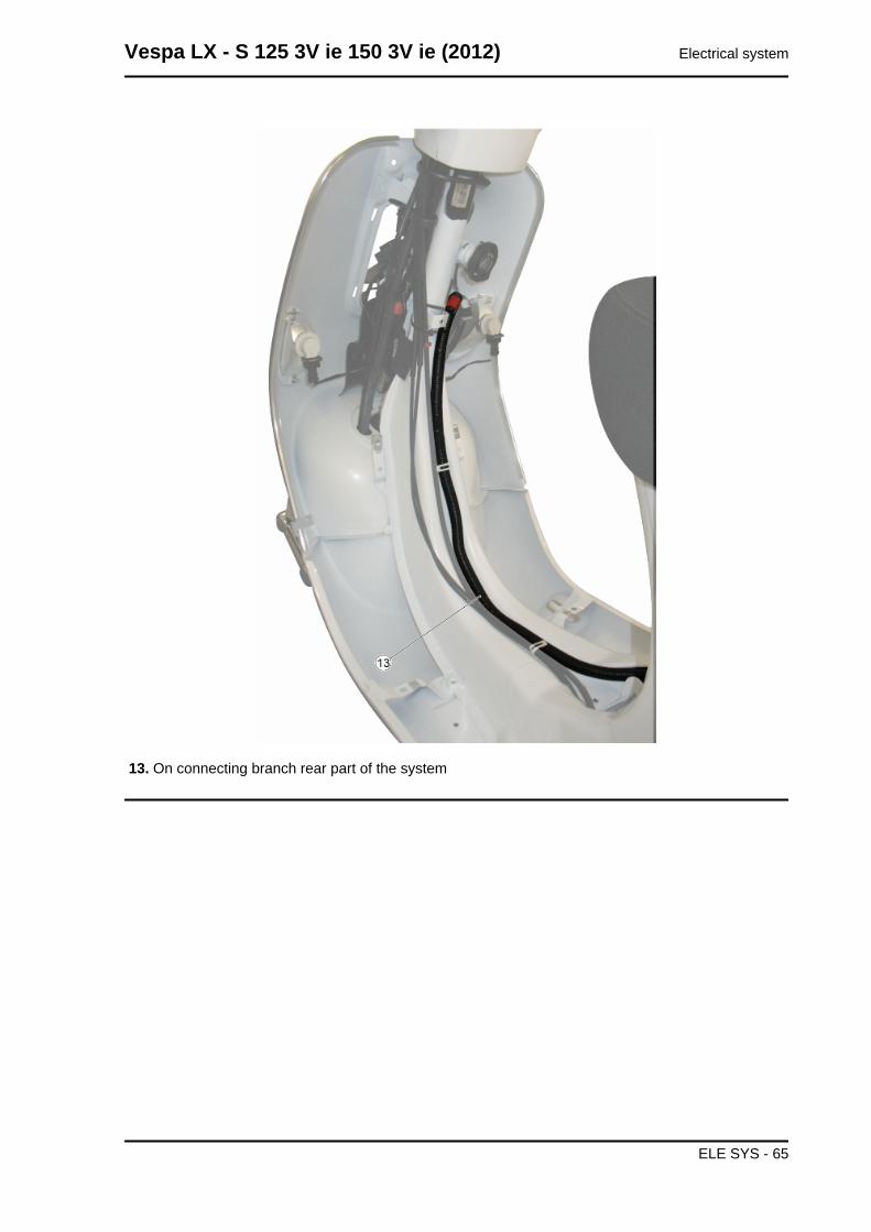
13. On connecting branch rear part of the system
Vespa LX - S 125 3V ie 150 3V ie (2012) Electrical system
ELE SYS - 65
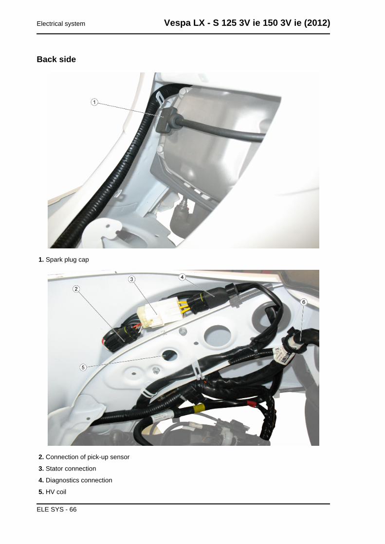
Back side
1. Spark plug cap
2. Connection of pick-up sensor
3. Stator connection
4. Diagnostics connection
5. HV coil
Electrical system Vespa LX - S 125 3V ie 150 3V ie (2012)
ELE SYS - 66
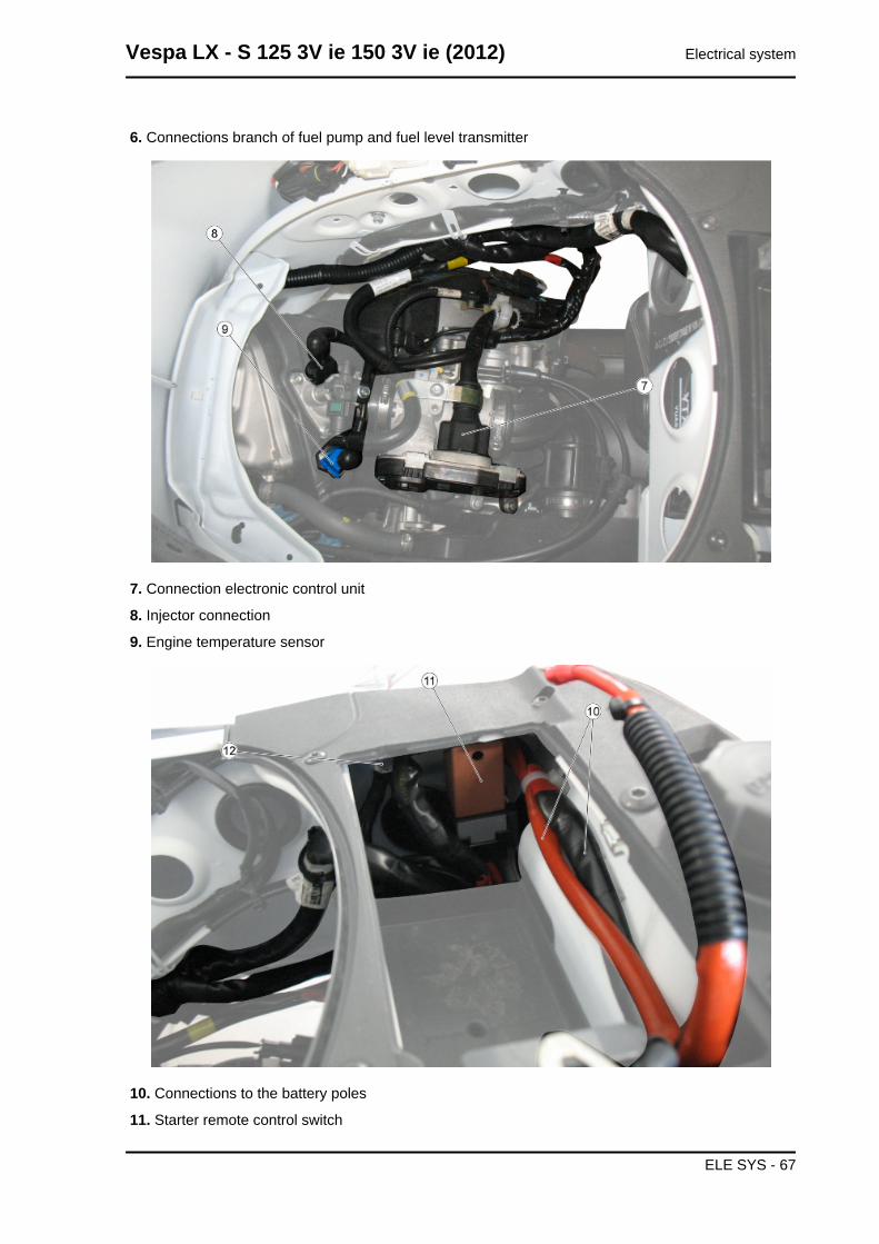
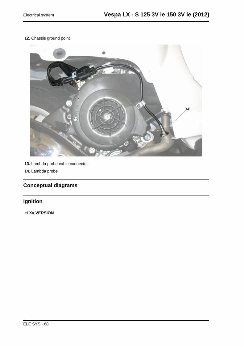
6. Connections branch of fuel pump and fuel level transmitter
7. Connection electronic control unit
8. Injector connection
9. Engine temperature sensor
10. Connections to the battery poles
11. Starter remote control switch
Vespa LX - S 125 3V ie 150 3V ie (2012) Electrical system
ELE SYS - 67
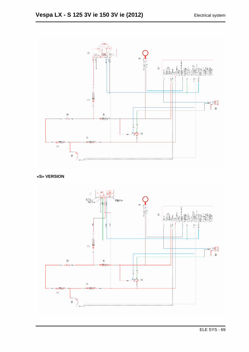
12. Chassis ground point
13. Lambda probe cable connector
14. Lambda probe
Conceptual diagrams
Ignition
«LX» VERSION
Electrical system Vespa LX - S 125 3V ie 150 3V ie (2012)
ELE SYS - 68
«S» VERSION
Vespa LX - S 125 3V ie 150 3V ie (2012) Electrical system
ELE SYS - 69
KEY
1. Instrument panel
11. Fuses No. 3, 4, 6;
14. Fuse No. 2
15. Ignition switch
18. Fuse No. 1
21. Battery
23. Injection load relay
28. H.V. coil
34. Electronic control unit
35. Immobilizer Aerial
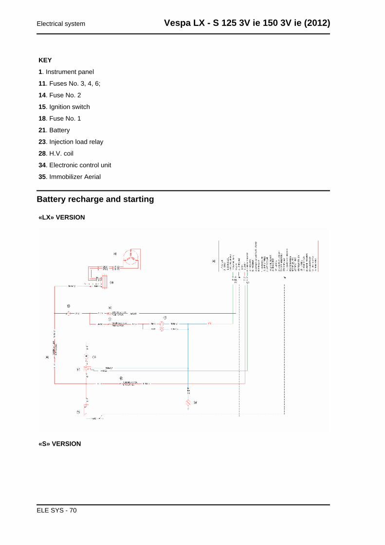
Battery recharge and starting
«LX» VERSION
«S» VERSION
Electrical system Vespa LX - S 125 3V ie 150 3V ie (2012)
ELE SYS - 70
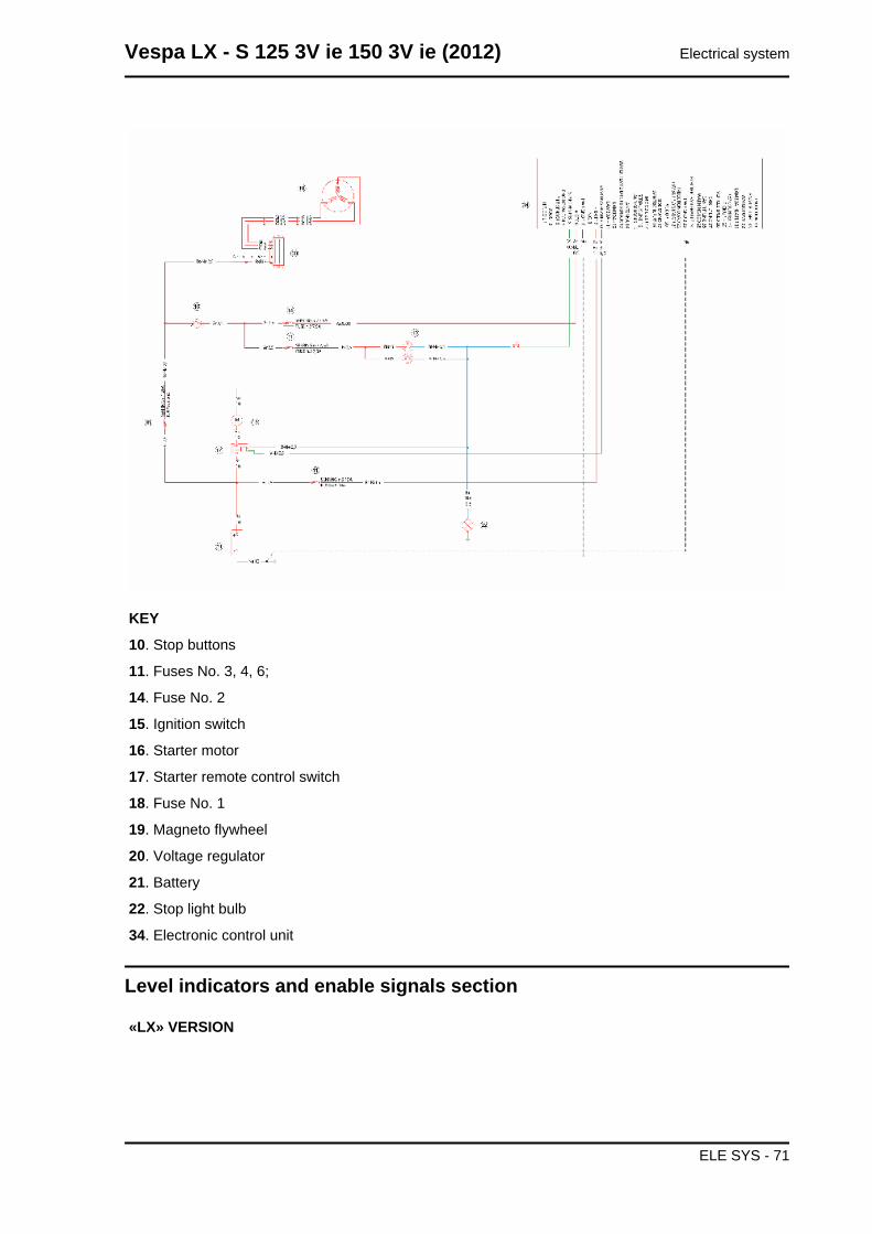
KEY
10. Stop buttons
11. Fuses No. 3, 4, 6;
14. Fuse No. 2
15. Ignition switch
16. Starter motor
17. Starter remote control switch
18. Fuse No. 1
19. Magneto flywheel
20. Voltage regulator
21. Battery
22. Stop light bulb
34. Electronic control unit
Level indicators and enable signals section
«LX» VERSION
Vespa LX - S 125 3V ie 150 3V ie (2012) Electrical system
ELE SYS - 71
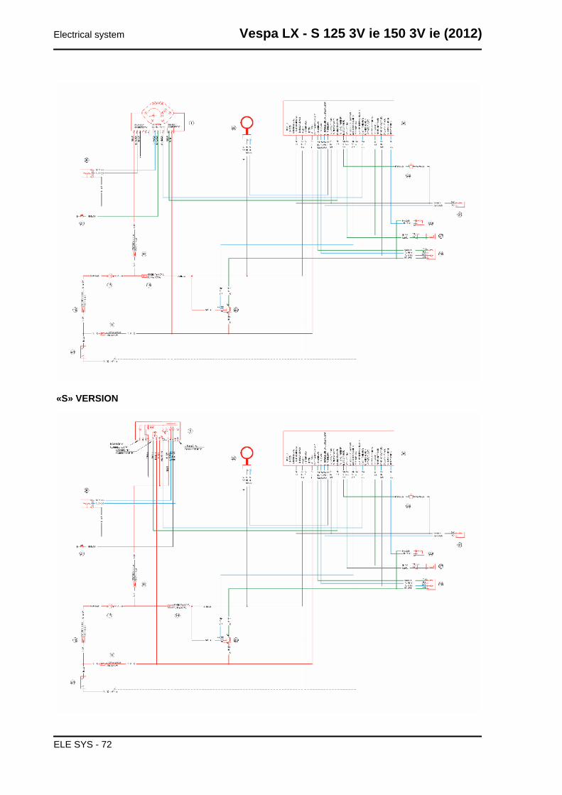
«S» VERSION
Electrical system Vespa LX - S 125 3V ie 150 3V ie (2012)
ELE SYS - 72
KEY
1. Instrument panel
11. Fuses No. 3, 4, 6;
14. Fuse No. 2
15. Ignition switch
18. Fuse No. 1
21. Battery
23. Injection load relay
26. Lambda probe
27. Engine speed sensor
30. Injector
31. Engine temperature sensor
33. Side stand switch
34. Electronic control unit
35. Immobilizer Aerial
36. Fuel level transmitter
37. Oil pressure sensor
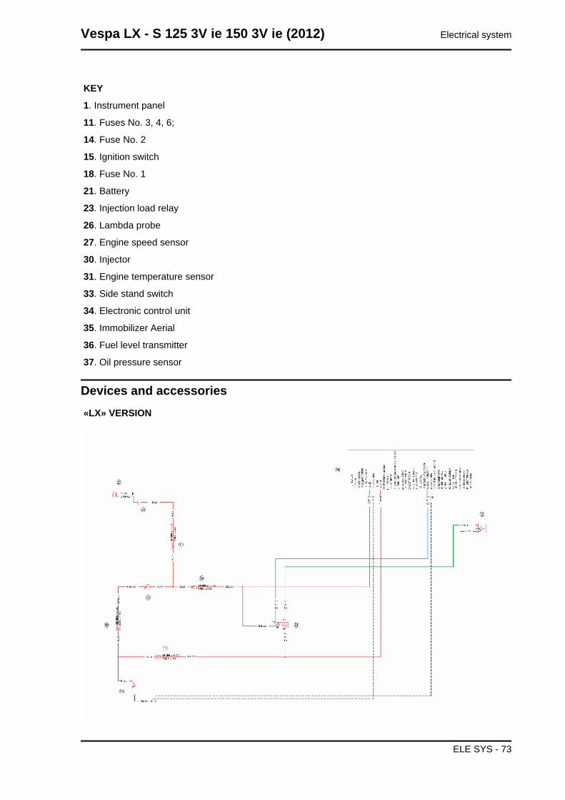
Devices and accessories«LX» VERSION
Vespa LX - S 125 3V ie 150 3V ie (2012) Electrical system
ELE SYS - 73
«S» VERSION
KEY
11. Fuses No. 3, 4, 6;
14. Fuse No. 2
15. Ignition switch
18. Fuse No. 1
21. Battery
23. Injection load relay
24. Horn button
25. Horn
32. Fuel pump
34. Electronic control unit
Lights and turn indicators
«LX» VERSION
Electrical system Vespa LX - S 125 3V ie 150 3V ie (2012)
ELE SYS - 74
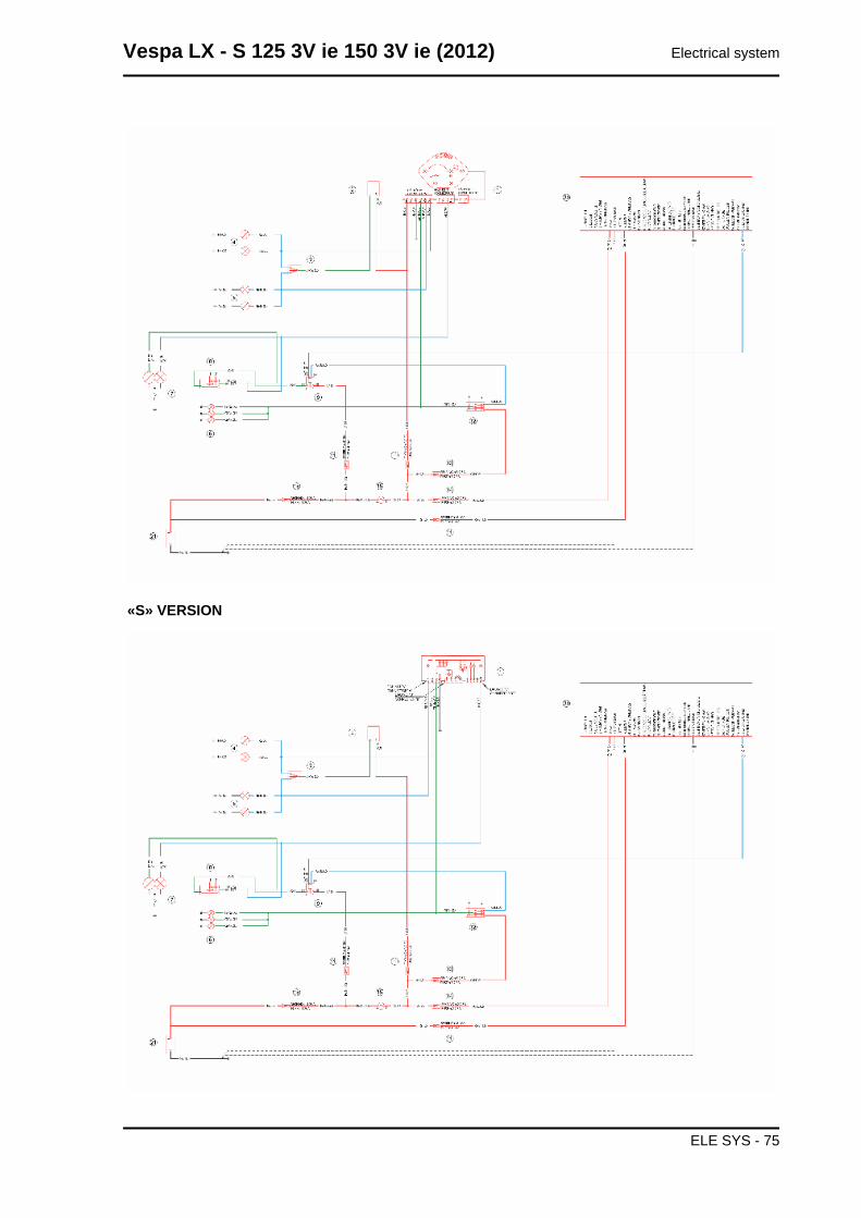
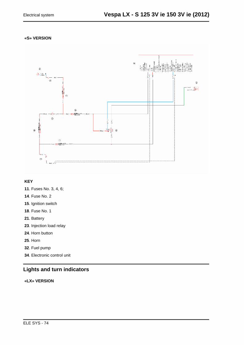
«S» VERSION
Vespa LX - S 125 3V ie 150 3V ie (2012) Electrical system
ELE SYS - 75
KEY
1. Instrument panel
2. Turn indicator control device
3. Turn indicator switch
4. Left turn indicator bulbs
5. Right turn indicator bulbs
6. Daylight running light bulbs and license plate light
7. Headlight with twin-filament bulb
8. Light switch
9. Headlight relay
11. Fuses No. 3, 4, 6;
12. Light switch
13. Fuse No. 5
14. Fuse No. 2
15. Ignition switch
18. Fuse No. 1
21. Battery
34. Electronic control unit
INJECTION
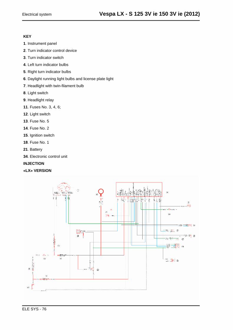
«LX» VERSION
Electrical system Vespa LX - S 125 3V ie 150 3V ie (2012)
ELE SYS - 76
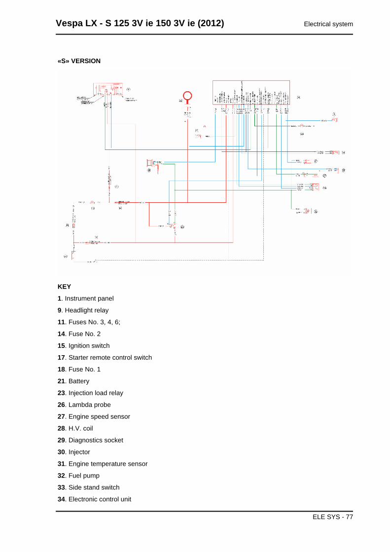
«S» VERSION
KEY
1. Instrument panel
9. Headlight relay
11. Fuses No. 3, 4, 6;
14. Fuse No. 2
15. Ignition switch
17. Starter remote control switch
18. Fuse No. 1
21. Battery
23. Injection load relay
26. Lambda probe
27. Engine speed sensor
28. H.V. coil
29. Diagnostics socket
30. Injector
31. Engine temperature sensor
32. Fuel pump
33. Side stand switch
34. Electronic control unit
Vespa LX - S 125 3V ie 150 3V ie (2012) Electrical system
ELE SYS - 77
35. Immobilizer Aerial
Checks and inspections
Immobiliser
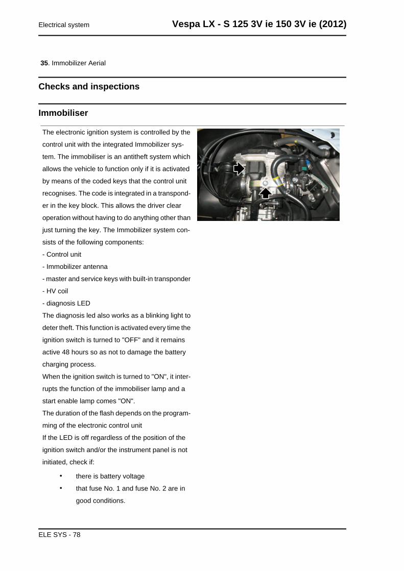
The electronic ignition system is controlled by the
control unit with the integrated Immobilizer sys-
tem. The immobiliser is an antitheft system which
allows the vehicle to function only if it is activated
by means of the coded keys that the control unit
recognises. The code is integrated in a transpond-
er in the key block. This allows the driver clear
operation without having to do anything other than
just turning the key. The Immobilizer system con-
sists of the following components:
- Control unit
- Immobilizer antenna
- master and service keys with built-in transponder
- HV coil
- diagnosis LED
The diagnosis led also works as a blinking light to
deter theft. This function is activated every time the
ignition switch is turned to "OFF" and it remains
active 48 hours so as not to damage the battery
charging process.
When the ignition switch is turned to "ON", it inter-
rupts the function of the immobiliser lamp and a
start enable lamp comes "ON".
The duration of the flash depends on the program-
ming of the electronic control unit
If the LED is off regardless of the position of the
ignition switch and/or the instrument panel is not
initiated, check if:
• there is battery voltage
• that fuse No. 1 and fuse No. 2 are in
good conditions.
Electrical system Vespa LX - S 125 3V ie 150 3V ie (2012)
ELE SYS - 78
• there is power to the control unit as
specified below:
Remove the connector mounting bracket shown in
the photograph and disconnect the connector from
the control unit. Check the following conditions:
With the key switch set to OFF:
• there is battery voltage between terminals 7-9 and terminal 9-chassis ground (fixed power supply). If
there is no voltage check that fuse 2 and its cable are in working order.
With the key switch in the ON position:
• there is battery voltage between terminals 6-7 and terminal 6-chassis ground (fixed power supply). If
there is no voltage, check the ignition key contacts, that fuse 6 and its cable are in working order.
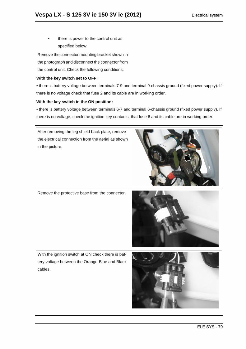
After removing the leg shield back plate, remove
the electrical connection from the aerial as shown
in the picture.
Remove the protective base from the connector.
With the ignition switch at ON check there is bat-
tery voltage between the Orange-Blue and Black
cables.
Vespa LX - S 125 3V ie 150 3V ie (2012) Electrical system
ELE SYS - 79
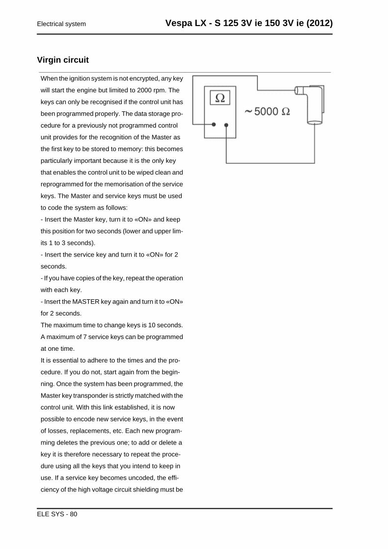
Virgin circuit
When the ignition system is not encrypted, any key
will start the engine but limited to 2000 rpm. The
keys can only be recognised if the control unit has
been programmed properly. The data storage pro-
cedure for a previously not programmed control
unit provides for the recognition of the Master as
the first key to be stored to memory: this becomes
particularly important because it is the only key
that enables the control unit to be wiped clean and
reprogrammed for the memorisation of the service
keys. The Master and service keys must be used
to code the system as follows:
- Insert the Master key, turn it to «ON» and keep
this position for two seconds (lower and upper lim-
its 1 to 3 seconds).
- Insert the service key and turn it to «ON» for 2
seconds.
- If you have copies of the key, repeat the operation
with each key.
- Insert the MASTER key again and turn it to «ON»
for 2 seconds.
The maximum time to change keys is 10 seconds.
A maximum of 7 service keys can be programmed
at one time.
It is essential to adhere to the times and the pro-
cedure. If you do not, start again from the begin-
ning. Once the system has been programmed, the
Master key transponder is strictly matched with the
control unit. With this link established, it is now
possible to encode new service keys, in the event
of losses, replacements, etc. Each new program-
ming deletes the previous one; to add or delete a
key it is therefore necessary to repeat the proce-
dure using all the keys that you intend to keep in
use. If a service key becomes uncoded, the effi-
ciency of the high voltage circuit shielding must be
Electrical system Vespa LX - S 125 3V ie 150 3V ie (2012)
ELE SYS - 80
thoroughly inspected: In any case it is advisable to
use resistor spark plugs.
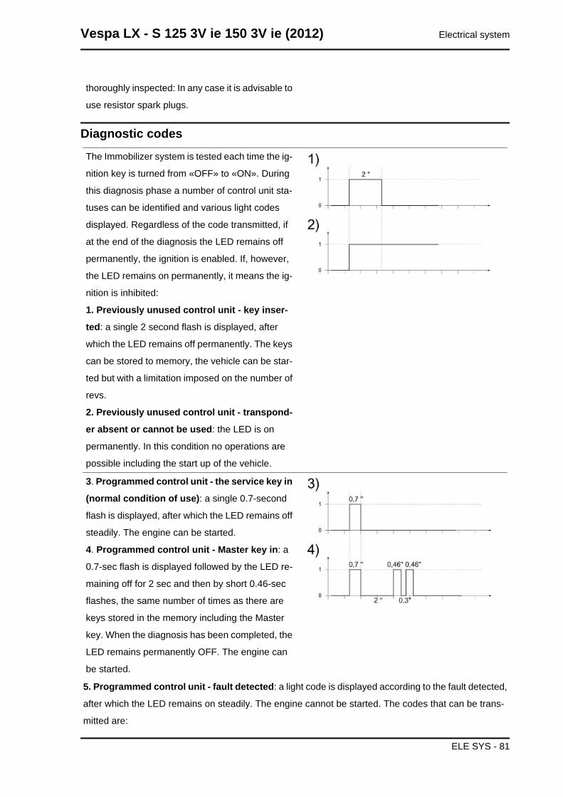
Diagnostic codesThe Immobilizer system is tested each time the ig-
nition key is turned from «OFF» to «ON». During
this diagnosis phase a number of control unit sta-
tuses can be identified and various light codes
displayed. Regardless of the code transmitted, if
at the end of the diagnosis the LED remains off
permanently, the ignition is enabled. If, however,
the LED remains on permanently, it means the ig-
nition is inhibited:
1. Previously unused control unit - key inser-
ted: a single 2 second flash is displayed, after
which the LED remains off permanently. The keys
can be stored to memory, the vehicle can be star-
ted but with a limitation imposed on the number of
revs.
2. Previously unused control unit - transpond-
er absent or cannot be used: the LED is on
permanently. In this condition no operations are
possible including the start up of the vehicle.
3. Programmed control unit - the service key in
(normal condition of use): a single 0.7-second
flash is displayed, after which the LED remains off
steadily. The engine can be started.
4. Programmed control unit - Master key in: a
0.7-sec flash is displayed followed by the LED re-
maining off for 2 sec and then by short 0.46-sec
flashes, the same number of times as there are
keys stored in the memory including the Master
key. When the diagnosis has been completed, the
LED remains permanently OFF. The engine can
be started.
5. Programmed control unit - fault detected: a light code is displayed according to the fault detected,
after which the LED remains on steadily. The engine cannot be started. The codes that can be trans-
mitted are:
Vespa LX - S 125 3V ie 150 3V ie (2012) Electrical system
ELE SYS - 81
• 1-flash code
• 2-flash code
• 3-flash code
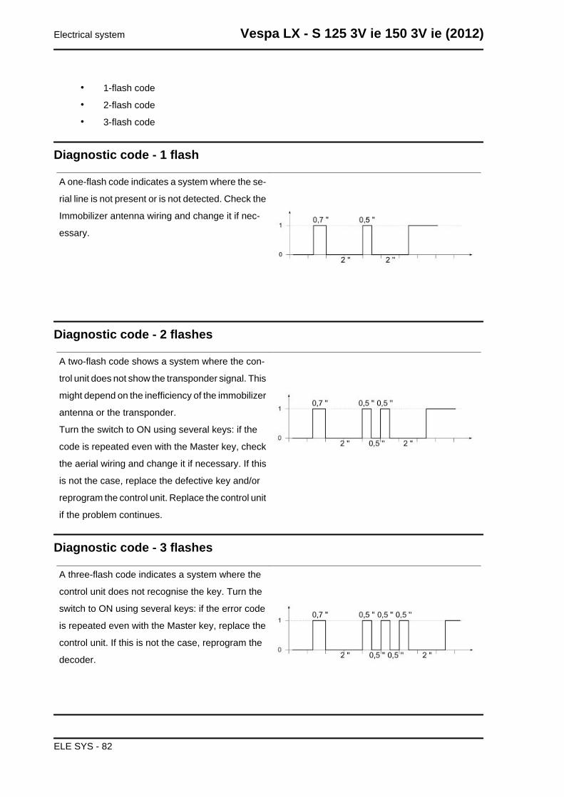
Diagnostic code - 1 flash
A one-flash code indicates a system where the se-
rial line is not present or is not detected. Check the
Immobilizer antenna wiring and change it if nec-
essary.
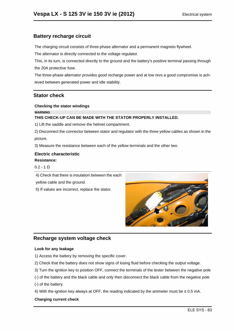
Diagnostic code - 2 flashes
A two-flash code shows a system where the con-
trol unit does not show the transponder signal. This
might depend on the inefficiency of the immobilizer
antenna or the transponder.
Turn the switch to ON using several keys: if the
code is repeated even with the Master key, check
the aerial wiring and change it if necessary. If this
is not the case, replace the defective key and/or
reprogram the control unit. Replace the control unit
if the problem continues.
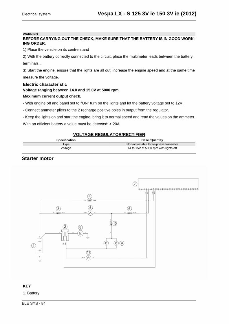
Diagnostic code - 3 flashes
A three-flash code indicates a system where the
control unit does not recognise the key. Turn the
switch to ON using several keys: if the error code
is repeated even with the Master key, replace the
control unit. If this is not the case, reprogram the
decoder.
Electrical system Vespa LX - S 125 3V ie 150 3V ie (2012)
ELE SYS - 82
Battery recharge circuit
The charging circuit consists of three-phase alternator and a permanent magneto flywheel.
The alternator is directly connected to the voltage regulator.
This, in its turn, is connected directly to the ground and the battery's positive terminal passing through
the 20A protective fuse.
The three-phase alternator provides good recharge power and at low revs a good compromise is ach-
ieved between generated power and idle stability.
Stator check
Checking the stator windingsWARNINGTHIS CHECK-UP CAN BE MADE WITH THE STATOR PROPERLY INSTALLED.1) Lift the saddle and remove the helmet compartment.
2) Disconnect the connector between stator and regulator with the three yellow cables as shown in the
picture.
3) Measure the resistance between each of the yellow terminals and the other two.
Electric characteristicResistance:0.2 - 1 Ω
4) Check that there is insulation between the each
yellow cable and the ground.
5) If values are incorrect, replace the stator.
Recharge system voltage check
Look for any leakage
1) Access the battery by removing the specific cover.
2) Check that the battery does not show signs of losing fluid before checking the output voltage.
3) Turn the ignition key to position OFF, connect the terminals of the tester between the negative pole
(-) of the battery and the black cable and only then disconnect the black cable from the negative pole
(-) of the battery.
4) With the ignition key always at OFF, the reading indicated by the ammeter must be ≤ 0.5 mA.
Charging current check
Vespa LX - S 125 3V ie 150 3V ie (2012) Electrical system
ELE SYS - 83
WARNINGBEFORE CARRYING OUT THE CHECK, MAKE SURE THAT THE BATTERY IS IN GOOD WORK-ING ORDER.1) Place the vehicle on its centre stand
2) With the battery correctly connected to the circuit, place the multimeter leads between the battery
terminals..
3) Start the engine, ensure that the lights are all out, increase the engine speed and at the same time
measure the voltage.
Electric characteristicVoltage ranging between 14.0 and 15.0V at 5000 rpm.Maximum current output check.
- With engine off and panel set to "ON" turn on the lights and let the battery voltage set to 12V.
- Connect ammeter pliers to the 2 recharge positive poles in output from the regulator.
- Keep the lights on and start the engine, bring it to normal speed and read the values on the ammeter.
With an efficient battery a value must be detected: > 20A
VOLTAGE REGULATOR/RECTIFIERSpecification Desc./Quantity
Type Non-adjustable three-phase transistorVoltage 14 to 15V at 5000 rpm with lights off
Starter motor
KEY
1. Battery
Electrical system Vespa LX - S 125 3V ie 150 3V ie (2012)
ELE SYS - 84
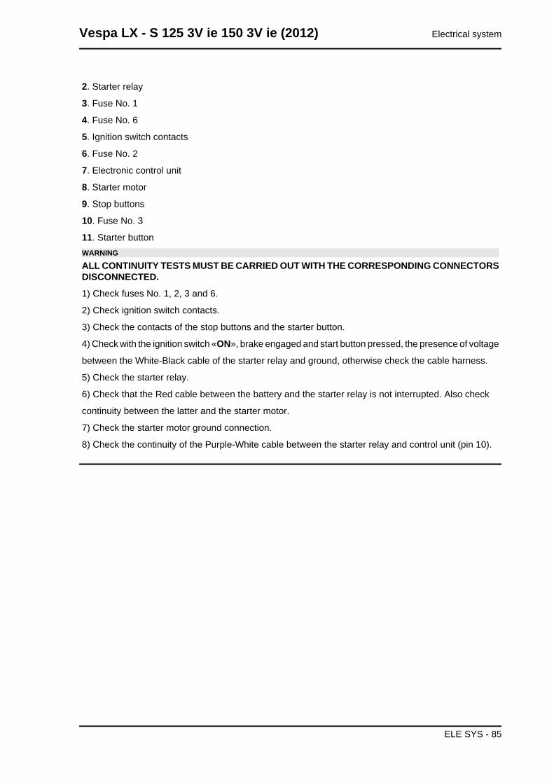
2. Starter relay
3. Fuse No. 1
4. Fuse No. 6
5. Ignition switch contacts
6. Fuse No. 2
7. Electronic control unit
8. Starter motor
9. Stop buttons
10. Fuse No. 3
11. Starter buttonWARNING
ALL CONTINUITY TESTS MUST BE CARRIED OUT WITH THE CORRESPONDING CONNECTORSDISCONNECTED.
1) Check fuses No. 1, 2, 3 and 6.
2) Check ignition switch contacts.
3) Check the contacts of the stop buttons and the starter button.
4) Check with the ignition switch «ON», brake engaged and start button pressed, the presence of voltage
between the White-Black cable of the starter relay and ground, otherwise check the cable harness.
5) Check the starter relay.
6) Check that the Red cable between the battery and the starter relay is not interrupted. Also check
continuity between the latter and the starter motor.
7) Check the starter motor ground connection.
8) Check the continuity of the Purple-White cable between the starter relay and control unit (pin 10).
Vespa LX - S 125 3V ie 150 3V ie (2012) Electrical system
ELE SYS - 85
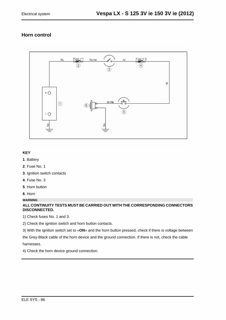
Horn control
KEY
1. Battery
2. Fuse No. 1
3. Ignition switch contacts
4. Fuse No. 3
5. Horn button
6. HornWARNING
ALL CONTINUITY TESTS MUST BE CARRIED OUT WITH THE CORRESPONDING CONNECTORSDISCONNECTED.
1) Check fuses No. 1 and 3.
2) Check the ignition switch and horn button contacts.
3) With the ignition switch set to «ON» and the horn button pressed, check if there is voltage between
the Grey-Black cable of the horn device and the ground connection. If there is not, check the cable
harnesses.
4) Check the horn device ground connection.
Electrical system Vespa LX - S 125 3V ie 150 3V ie (2012)
ELE SYS - 86
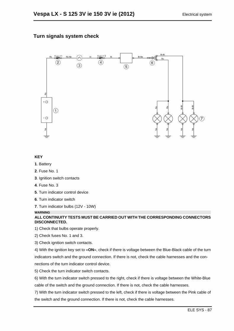
Turn signals system check
KEY
1. Battery
2. Fuse No. 1
3. Ignition switch contacts
4. Fuse No. 3
5. Turn indicator control device
6. Turn indicator switch
7. Turn indicator bulbs (12V - 10W)WARNINGALL CONTINUITY TESTS MUST BE CARRIED OUT WITH THE CORRESPONDING CONNECTORSDISCONNECTED.1) Check that bulbs operate properly.
2) Check fuses No. 1 and 3.
3) Check ignition switch contacts.
4) With the ignition key set to «ON», check if there is voltage between the Blue-Black cable of the turn
indicators switch and the ground connection. If there is not, check the cable harnesses and the con-
nections of the turn indicator control device.
5) Check the turn indicator switch contacts.
6) With the turn indicator switch pressed to the right, check if there is voltage between the White-Blue
cable of the switch and the ground connection. If there is not, check the cable harnesses.
7) With the turn indicator switch pressed to the left, check if there is voltage between the Pink cable of
the switch and the ground connection. If there is not, check the cable harnesses.
Vespa LX - S 125 3V ie 150 3V ie (2012) Electrical system
ELE SYS - 87
8) Check that the cable harnesses of the bulbs and their ground connection are not interrupted.
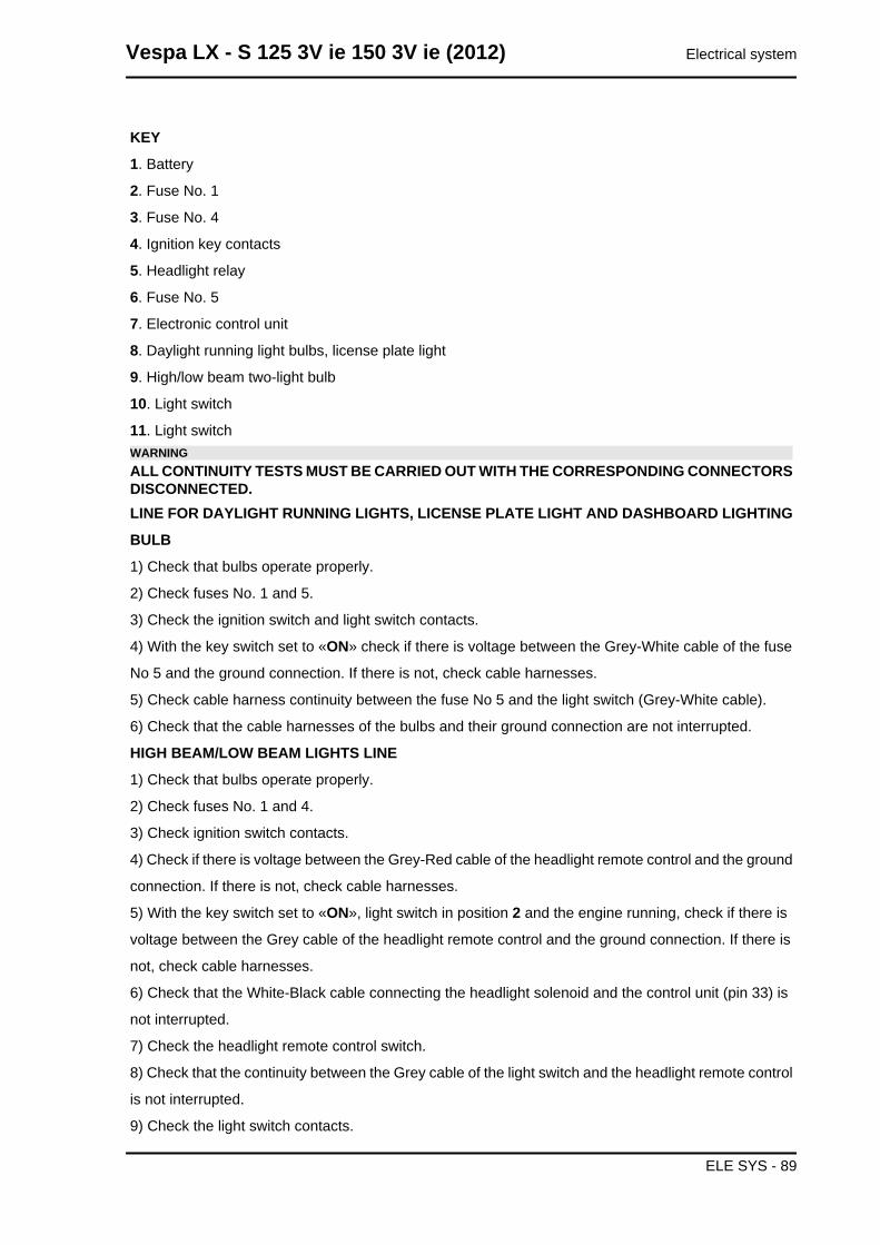
level indicatorsWARNINGALL CONTINUITY TESTS MUST BE CARRIED OUT WITH THE CORRESPONDING CONNECTORSDISCONNECTED.If faults are detected:
1) With a multimeter, check resistance values be-
tween the White-Green cable and the Black cable
of the fuel level transmitter under different condi-
tions.
2) If the transmitter operates correctly but the in-
dication on the instrument panel is not exact,
check that the cable harnesses between them are
not interrupted.
Electric characteristicResistance value when the tank is full<= 7 Ω
Resistance value when the tank is empty90 +13/-3 Ω
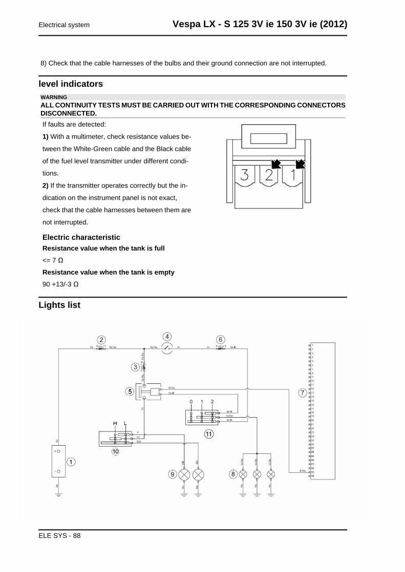
Lights list
Electrical system Vespa LX - S 125 3V ie 150 3V ie (2012)
ELE SYS - 88
KEY
1. Battery
2. Fuse No. 1
3. Fuse No. 4
4. Ignition key contacts
5. Headlight relay
6. Fuse No. 5
7. Electronic control unit
8. Daylight running light bulbs, license plate light
9. High/low beam two-light bulb
10. Light switch
11. Light switchWARNINGALL CONTINUITY TESTS MUST BE CARRIED OUT WITH THE CORRESPONDING CONNECTORSDISCONNECTED.LINE FOR DAYLIGHT RUNNING LIGHTS, LICENSE PLATE LIGHT AND DASHBOARD LIGHTING
BULB
1) Check that bulbs operate properly.
2) Check fuses No. 1 and 5.
3) Check the ignition switch and light switch contacts.
4) With the key switch set to «ON» check if there is voltage between the Grey-White cable of the fuse
No 5 and the ground connection. If there is not, check cable harnesses.
5) Check cable harness continuity between the fuse No 5 and the light switch (Grey-White cable).
6) Check that the cable harnesses of the bulbs and their ground connection are not interrupted.
HIGH BEAM/LOW BEAM LIGHTS LINE
1) Check that bulbs operate properly.
2) Check fuses No. 1 and 4.
3) Check ignition switch contacts.
4) Check if there is voltage between the Grey-Red cable of the headlight remote control and the ground
connection. If there is not, check cable harnesses.
5) With the key switch set to «ON», light switch in position 2 and the engine running, check if there is
voltage between the Grey cable of the headlight remote control and the ground connection. If there is
not, check cable harnesses.
6) Check that the White-Black cable connecting the headlight solenoid and the control unit (pin 33) is
not interrupted.
7) Check the headlight remote control switch.
8) Check that the continuity between the Grey cable of the light switch and the headlight remote control
is not interrupted.
9) Check the light switch contacts.
Vespa LX - S 125 3V ie 150 3V ie (2012) Electrical system
ELE SYS - 89
10) Check that the cable harnesses of the bulbs and their ground connection are not interrupted.
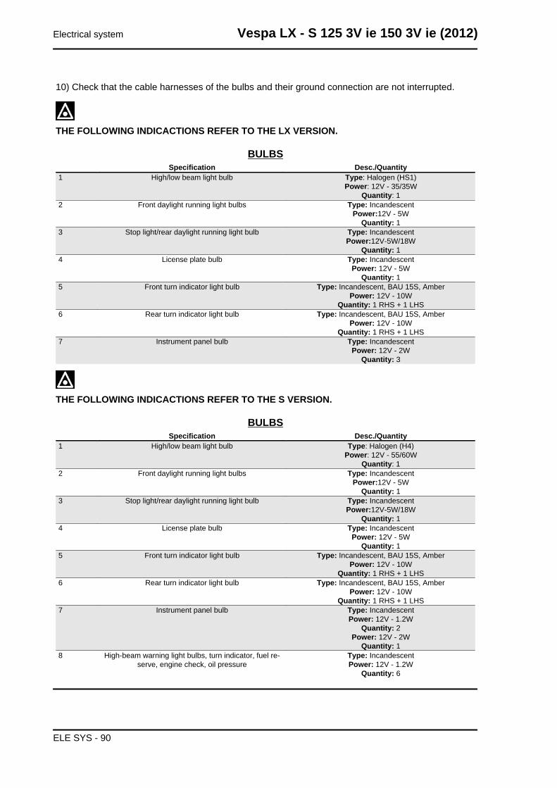
THE FOLLOWING INDICACTIONS REFER TO THE LX VERSION.
BULBSSpecification Desc./Quantity
1 High/low beam light bulb Type: Halogen (HS1)Power: 12V - 35/35W
Quantity: 12 Front daylight running light bulbs Type: Incandescent
Power:12V - 5WQuantity: 1
3 Stop light/rear daylight running light bulb Type: IncandescentPower:12V-5W/18W
Quantity: 14 License plate bulb Type: Incandescent
Power: 12V - 5WQuantity: 1
5 Front turn indicator light bulb Type: Incandescent, BAU 15S, AmberPower: 12V - 10W
Quantity: 1 RHS + 1 LHS6 Rear turn indicator light bulb Type: Incandescent, BAU 15S, Amber
Power: 12V - 10WQuantity: 1 RHS + 1 LHS
7 Instrument panel bulb Type: IncandescentPower: 12V - 2W
Quantity: 3
THE FOLLOWING INDICACTIONS REFER TO THE S VERSION.
BULBSSpecification Desc./Quantity
1 High/low beam light bulb Type: Halogen (H4)Power: 12V - 55/60W
Quantity: 12 Front daylight running light bulbs Type: Incandescent
Power:12V - 5WQuantity: 1
3 Stop light/rear daylight running light bulb Type: IncandescentPower:12V-5W/18W
Quantity: 14 License plate bulb Type: Incandescent
Power: 12V - 5WQuantity: 1
5 Front turn indicator light bulb Type: Incandescent, BAU 15S, AmberPower: 12V - 10W
Quantity: 1 RHS + 1 LHS6 Rear turn indicator light bulb Type: Incandescent, BAU 15S, Amber
Power: 12V - 10WQuantity: 1 RHS + 1 LHS
7 Instrument panel bulb Type: IncandescentPower: 12V - 1.2W
Quantity: 2Power: 12V - 2W
Quantity: 18 High-beam warning light bulbs, turn indicator, fuel re-
serve, engine check, oil pressureType: IncandescentPower: 12V - 1.2W
Quantity: 6
Electrical system Vespa LX - S 125 3V ie 150 3V ie (2012)
ELE SYS - 90
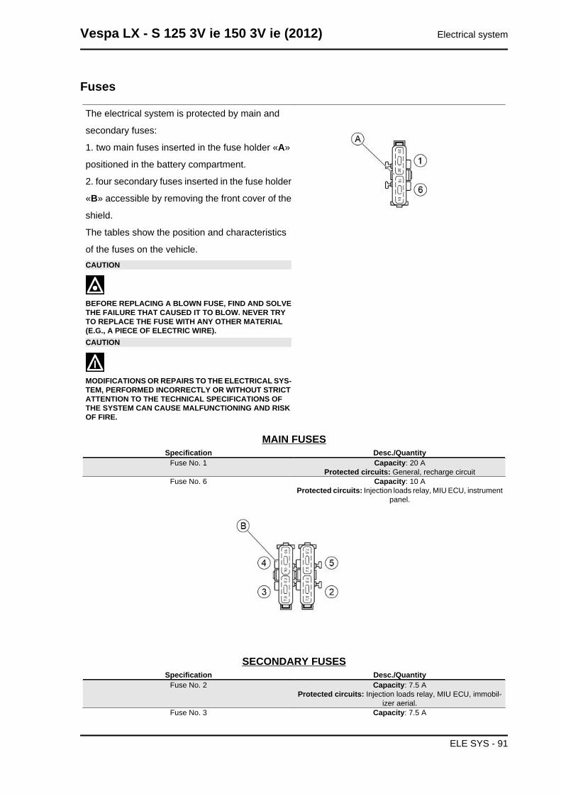
Fuses
The electrical system is protected by main and
secondary fuses:
1. two main fuses inserted in the fuse holder «A»
positioned in the battery compartment.
2. four secondary fuses inserted in the fuse holder
«B» accessible by removing the front cover of the
shield.
The tables show the position and characteristics
of the fuses on the vehicle.CAUTION
BEFORE REPLACING A BLOWN FUSE, FIND AND SOLVETHE FAILURE THAT CAUSED IT TO BLOW. NEVER TRYTO REPLACE THE FUSE WITH ANY OTHER MATERIAL(E.G., A PIECE OF ELECTRIC WIRE).CAUTION
MODIFICATIONS OR REPAIRS TO THE ELECTRICAL SYS-TEM, PERFORMED INCORRECTLY OR WITHOUT STRICTATTENTION TO THE TECHNICAL SPECIFICATIONS OFTHE SYSTEM CAN CAUSE MALFUNCTIONING AND RISKOF FIRE.
MAIN FUSESSpecification Desc./Quantity
Fuse No. 1 Capacity: 20 AProtected circuits: General, recharge circuit
Fuse No. 6 Capacity: 10 AProtected circuits: Injection loads relay, MIU ECU, instrument
panel.
SECONDARY FUSESSpecification Desc./Quantity
Fuse No. 2 Capacity: 7.5 AProtected circuits: Injection loads relay, MIU ECU, immobil-
izer aerial.Fuse No. 3 Capacity: 7.5 A
Vespa LX - S 125 3V ie 150 3V ie (2012) Electrical system
ELE SYS - 91
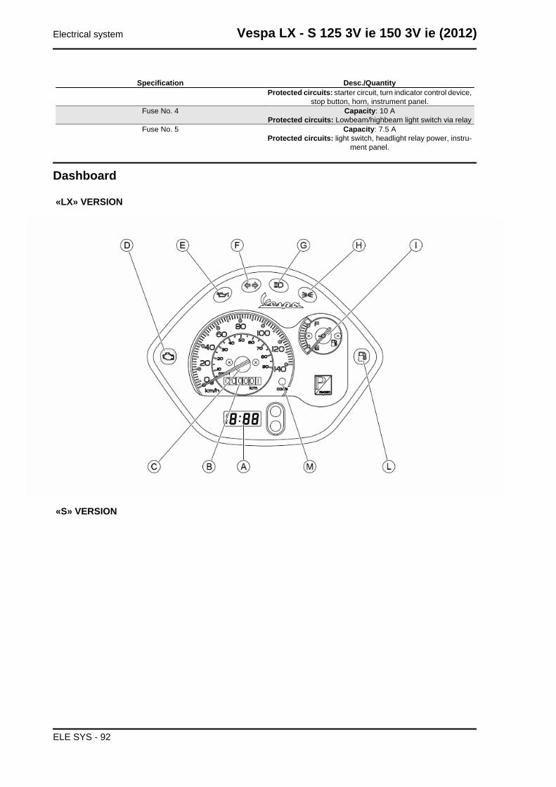
Specification Desc./QuantityProtected circuits: starter circuit, turn indicator control device,
stop button, horn, instrument panel.Fuse No. 4 Capacity: 10 A
Protected circuits: Lowbeam/highbeam light switch via relayFuse No. 5 Capacity: 7.5 A
Protected circuits: light switch, headlight relay power, instru-ment panel.
Dashboard
«LX» VERSION
«S» VERSION
Electrical system Vespa LX - S 125 3V ie 150 3V ie (2012)
ELE SYS - 92
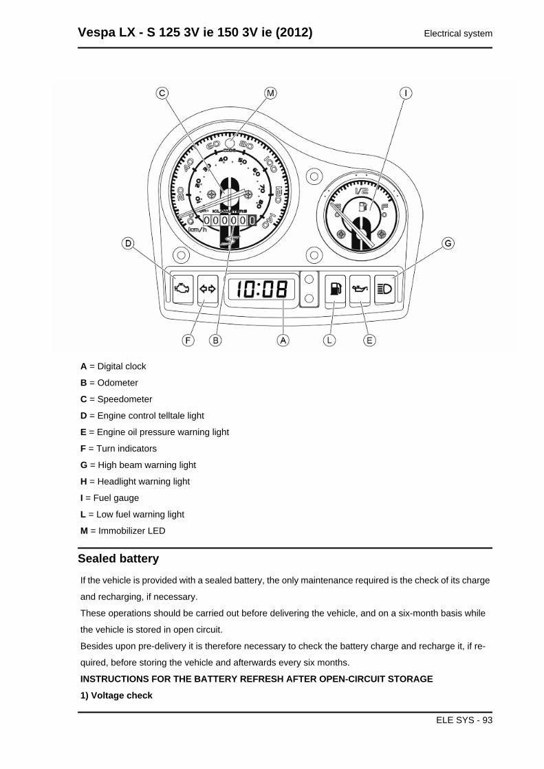
A = Digital clock
B = Odometer
C = Speedometer
D = Engine control telltale light
E = Engine oil pressure warning light
F = Turn indicators
G = High beam warning light
H = Headlight warning light
I = Fuel gauge
L = Low fuel warning light
M = Immobilizer LED
Sealed batteryIf the vehicle is provided with a sealed battery, the only maintenance required is the check of its charge
and recharging, if necessary.
These operations should be carried out before delivering the vehicle, and on a six-month basis while
the vehicle is stored in open circuit.
Besides upon pre-delivery it is therefore necessary to check the battery charge and recharge it, if re-
quired, before storing the vehicle and afterwards every six months.
INSTRUCTIONS FOR THE BATTERY REFRESH AFTER OPEN-CIRCUIT STORAGE
1) Voltage check
Vespa LX - S 125 3V ie 150 3V ie (2012) Electrical system
ELE SYS - 93
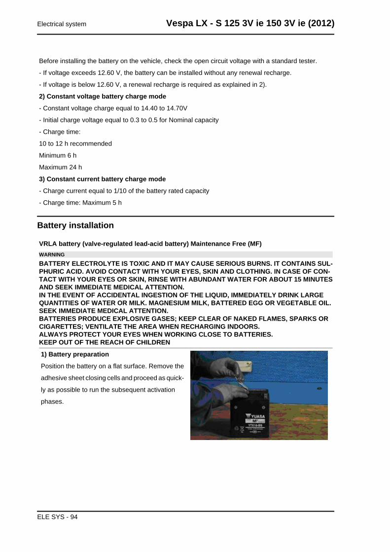
Before installing the battery on the vehicle, check the open circuit voltage with a standard tester.
- If voltage exceeds 12.60 V, the battery can be installed without any renewal recharge.
- If voltage is below 12.60 V, a renewal recharge is required as explained in 2).
2) Constant voltage battery charge mode
- Constant voltage charge equal to 14.40 to 14.70V
- Initial charge voltage equal to 0.3 to 0.5 for Nominal capacity
- Charge time:
10 to 12 h recommended
Minimum 6 h
Maximum 24 h
3) Constant current battery charge mode
- Charge current equal to 1/10 of the battery rated capacity
- Charge time: Maximum 5 h
Battery installation
VRLA battery (valve-regulated lead-acid battery) Maintenance Free (MF)WARNING
BATTERY ELECTROLYTE IS TOXIC AND IT MAY CAUSE SERIOUS BURNS. IT CONTAINS SUL-PHURIC ACID. AVOID CONTACT WITH YOUR EYES, SKIN AND CLOTHING. IN CASE OF CON-TACT WITH YOUR EYES OR SKIN, RINSE WITH ABUNDANT WATER FOR ABOUT 15 MINUTESAND SEEK IMMEDIATE MEDICAL ATTENTION.IN THE EVENT OF ACCIDENTAL INGESTION OF THE LIQUID, IMMEDIATELY DRINK LARGEQUANTITIES OF WATER OR MILK. MAGNESIUM MILK, BATTERED EGG OR VEGETABLE OIL.SEEK IMMEDIATE MEDICAL ATTENTION.BATTERIES PRODUCE EXPLOSIVE GASES; KEEP CLEAR OF NAKED FLAMES, SPARKS ORCIGARETTES; VENTILATE THE AREA WHEN RECHARGING INDOORS.ALWAYS PROTECT YOUR EYES WHEN WORKING CLOSE TO BATTERIES.KEEP OUT OF THE REACH OF CHILDREN
1) Battery preparation
Position the battery on a flat surface. Remove the
adhesive sheet closing cells and proceed as quick-
ly as possible to run the subsequent activation
phases.
Electrical system Vespa LX - S 125 3V ie 150 3V ie (2012)
ELE SYS - 94
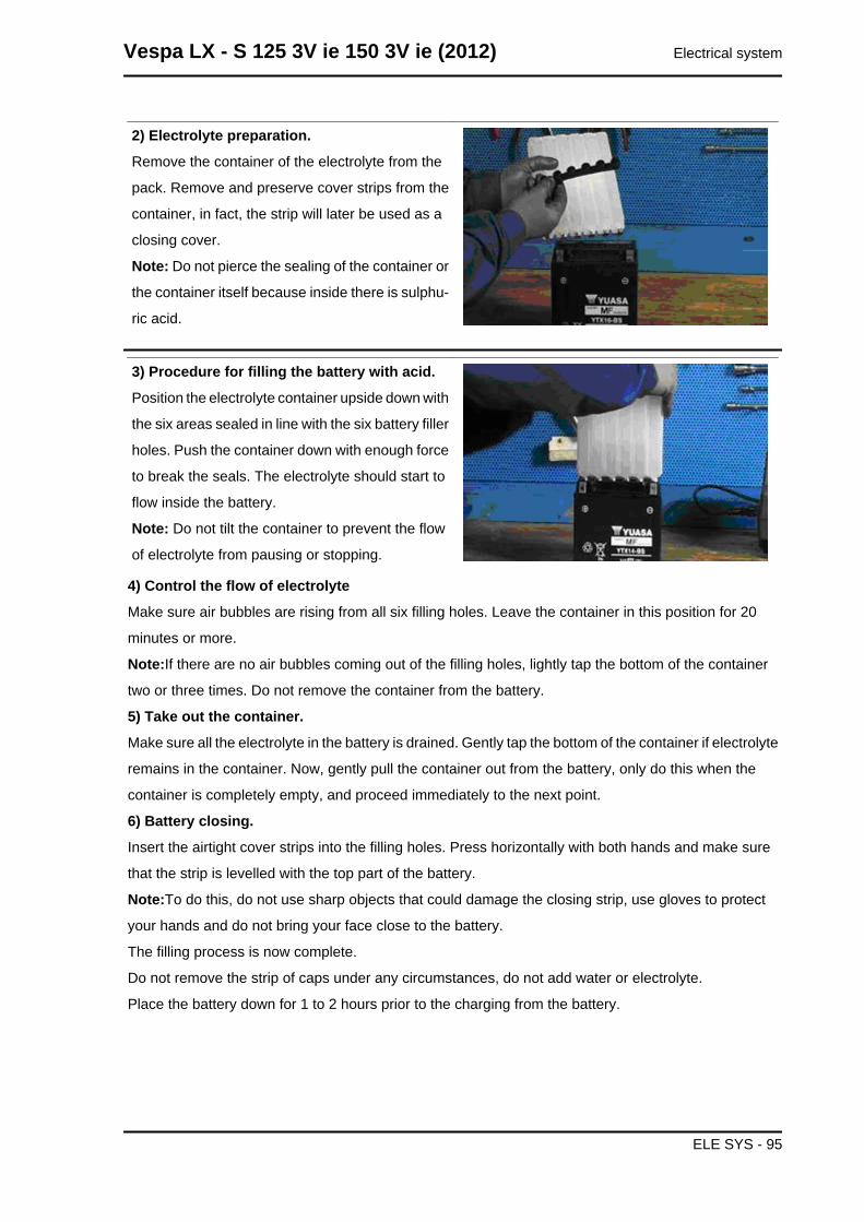
2) Electrolyte preparation.
Remove the container of the electrolyte from the
pack. Remove and preserve cover strips from the
container, in fact, the strip will later be used as a
closing cover.
Note: Do not pierce the sealing of the container or
the container itself because inside there is sulphu-
ric acid.
3) Procedure for filling the battery with acid.
Position the electrolyte container upside down with
the six areas sealed in line with the six battery filler
holes. Push the container down with enough force
to break the seals. The electrolyte should start to
flow inside the battery.
Note: Do not tilt the container to prevent the flow
of electrolyte from pausing or stopping.
4) Control the flow of electrolyte
Make sure air bubbles are rising from all six filling holes. Leave the container in this position for 20
minutes or more.
Note:If there are no air bubbles coming out of the filling holes, lightly tap the bottom of the container
two or three times. Do not remove the container from the battery.
5) Take out the container.
Make sure all the electrolyte in the battery is drained. Gently tap the bottom of the container if electrolyte
remains in the container. Now, gently pull the container out from the battery, only do this when the
container is completely empty, and proceed immediately to the next point.
6) Battery closing.
Insert the airtight cover strips into the filling holes. Press horizontally with both hands and make sure
that the strip is levelled with the top part of the battery.
Note:To do this, do not use sharp objects that could damage the closing strip, use gloves to protect
your hands and do not bring your face close to the battery.
The filling process is now complete.
Do not remove the strip of caps under any circumstances, do not add water or electrolyte.
Place the battery down for 1 to 2 hours prior to the charging from the battery.
Vespa LX - S 125 3V ie 150 3V ie (2012) Electrical system
ELE SYS - 95
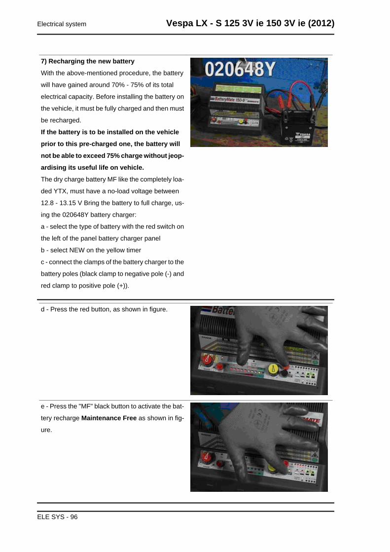
7) Recharging the new battery
With the above-mentioned procedure, the battery
will have gained around 70% - 75% of its total
electrical capacity. Before installing the battery on
the vehicle, it must be fully charged and then must
be recharged.
If the battery is to be installed on the vehicle
prior to this pre-charged one, the battery will
not be able to exceed 75% charge without jeop-
ardising its useful life on vehicle.
The dry charge battery MF like the completely loa-
ded YTX, must have a no-load voltage between
12.8 - 13.15 V Bring the battery to full charge, us-
ing the 020648Y battery charger:
a - select the type of battery with the red switch on
the left of the panel battery charger panel
b - select NEW on the yellow timer
c - connect the clamps of the battery charger to the
battery poles (black clamp to negative pole (-) and
red clamp to positive pole (+)).
d - Press the red button, as shown in figure.
e - Press the "MF" black button to activate the bat-
tery recharge Maintenance Free as shown in fig-
ure.
Electrical system Vespa LX - S 125 3V ie 150 3V ie (2012)
ELE SYS - 96
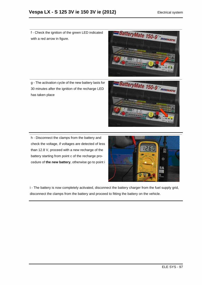
f - Check the ignition of the green LED indicated
with a red arrow in figure.
g - The activation cycle of the new battery lasts for
30 minutes after the ignition of the recharge LED
has taken place
h - Disconnect the clamps from the battery and
check the voltage, if voltages are detected of less
than 12.8 V, proceed with a new recharge of the
battery starting from point c of the recharge pro-
cedure of the new battery, otherwise go to point i
i - The battery is now completely activated, disconnect the battery charger from the fuel supply grid,
disconnect the clamps from the battery and proceed to fitting the battery on the vehicle.
Vespa LX - S 125 3V ie 150 3V ie (2012) Electrical system
ELE SYS - 97
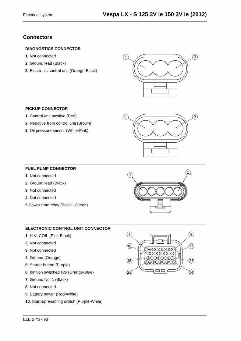
Connectors
DIAGNOSTICS CONNECTOR
1. Not connected
2. Ground lead (Black)
3. Electronic control unit (Orange-Black)
PICKUP CONNECTOR
1. Control unit positive (Red)
2. Negative from control unit (Brown)
3. Oil pressure sensor (White-Pink)
FUEL PUMP CONNECTOR
1. Not connected
2. Ground lead (Black)
3. Not connected
4. Not connected
5.Power from relay (Black - Green)
ELECTRONIC CONTROL UNIT CONNECTOR
1. H.V. COIL (Pink-Black)
2. Not connected
3. Not connected
4. Ground (Orange)
5. Starter button (Purple)
6. Ignition switched live (Orange-Blue)
7. Ground No. 1 (Black)
8. Not connected
9. Battery power (Red-White)
10. Start-up enabling switch (Purple-White)
Electrical system Vespa LX - S 125 3V ie 150 3V ie (2012)
ELE SYS - 98
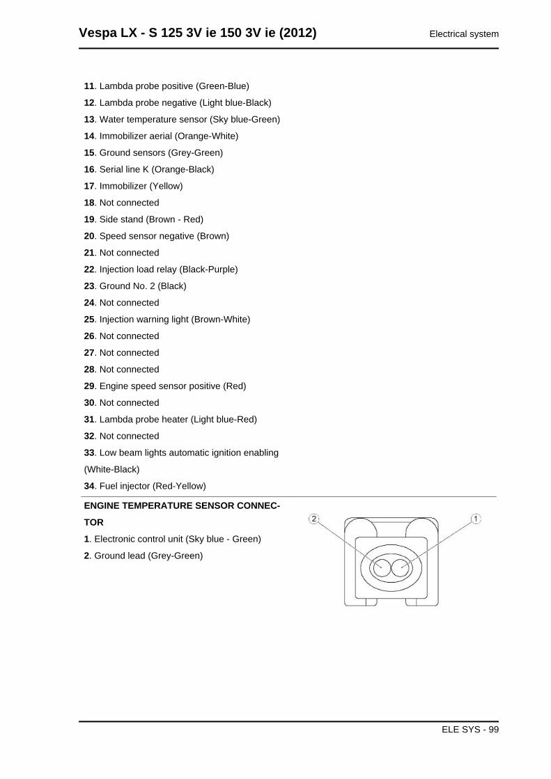
11. Lambda probe positive (Green-Blue)
12. Lambda probe negative (Light blue-Black)
13. Water temperature sensor (Sky blue-Green)
14. Immobilizer aerial (Orange-White)
15. Ground sensors (Grey-Green)
16. Serial line K (Orange-Black)
17. Immobilizer (Yellow)
18. Not connected
19. Side stand (Brown - Red)
20. Speed sensor negative (Brown)
21. Not connected
22. Injection load relay (Black-Purple)
23. Ground No. 2 (Black)
24. Not connected
25. Injection warning light (Brown-White)
26. Not connected
27. Not connected
28. Not connected
29. Engine speed sensor positive (Red)
30. Not connected
31. Lambda probe heater (Light blue-Red)
32. Not connected
33. Low beam lights automatic ignition enabling
(White-Black)
34. Fuel injector (Red-Yellow)
ENGINE TEMPERATURE SENSOR CONNEC-
TOR
1. Electronic control unit (Sky blue - Green)
2. Ground lead (Grey-Green)
Vespa LX - S 125 3V ie 150 3V ie (2012) Electrical system
ELE SYS - 99
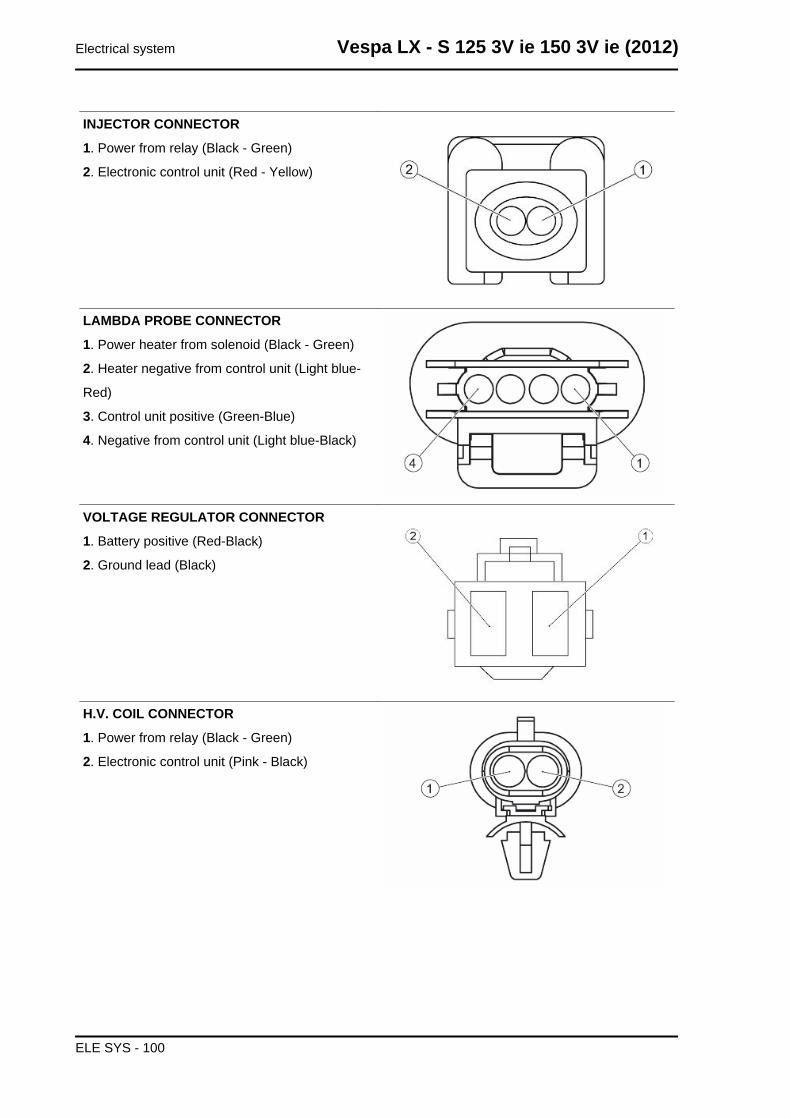
INJECTOR CONNECTOR
1. Power from relay (Black - Green)
2. Electronic control unit (Red - Yellow)
LAMBDA PROBE CONNECTOR
1. Power heater from solenoid (Black - Green)
2. Heater negative from control unit (Light blue-
Red)
3. Control unit positive (Green-Blue)
4. Negative from control unit (Light blue-Black)
VOLTAGE REGULATOR CONNECTOR
1. Battery positive (Red-Black)
2. Ground lead (Black)
H.V. COIL CONNECTOR
1. Power from relay (Black - Green)
2. Electronic control unit (Pink - Black)
Electrical system Vespa LX - S 125 3V ie 150 3V ie (2012)
ELE SYS - 100
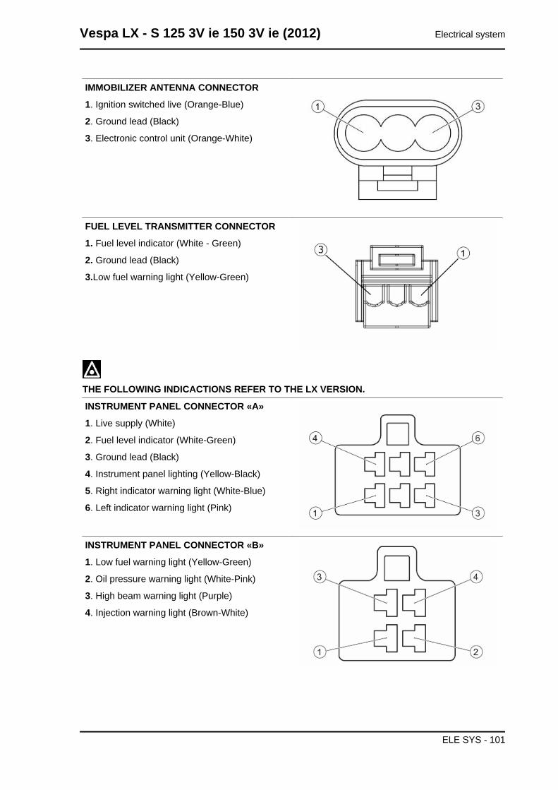
IMMOBILIZER ANTENNA CONNECTOR
1. Ignition switched live (Orange-Blue)
2. Ground lead (Black)
3. Electronic control unit (Orange-White)
FUEL LEVEL TRANSMITTER CONNECTOR
1. Fuel level indicator (White - Green)
2. Ground lead (Black)
3.Low fuel warning light (Yellow-Green)
THE FOLLOWING INDICACTIONS REFER TO THE LX VERSION.
INSTRUMENT PANEL CONNECTOR «A»
1. Live supply (White)
2. Fuel level indicator (White-Green)
3. Ground lead (Black)
4. Instrument panel lighting (Yellow-Black)
5. Right indicator warning light (White-Blue)
6. Left indicator warning light (Pink)
INSTRUMENT PANEL CONNECTOR «B»
1. Low fuel warning light (Yellow-Green)
2. Oil pressure warning light (White-Pink)
3. High beam warning light (Purple)
4. Injection warning light (Brown-White)
Vespa LX - S 125 3V ie 150 3V ie (2012) Electrical system
ELE SYS - 101
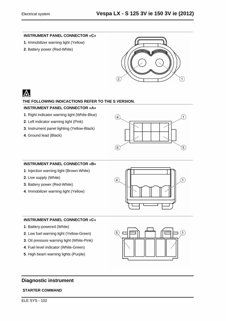
INSTRUMENT PANEL CONNECTOR «C»
1. Immobilizer warning light (Yellow)
2. Battery power (Red-White)
THE FOLLOWING INDICACTIONS REFER TO THE S VERSION.INSTRUMENT PANEL CONNECTOR «A»
1. Right indicator warning light (White-Blue)
2. Left indicator warning light (Pink)
3. Instrument panel lighting (Yellow-Black)
4. Ground lead (Black)
INSTRUMENT PANEL CONNECTOR «B»
1. Injection warning light (Brown-White)
2. Live supply (White)
3. Battery power (Red-White)
4. Immobilizer warning light (Yellow)
INSTRUMENT PANEL CONNECTOR «C»
1. Battery-powered (White)
2. Low fuel warning light (Yellow-Green)
3. Oil pressure warning light (White-Pink)
4. Fuel level indicator (White-Green)
5. High beam warning lights (Purple)
Diagnostic instrument
STARTER COMMAND
Electrical system Vespa LX - S 125 3V ie 150 3V ie (2012)
ELE SYS - 102
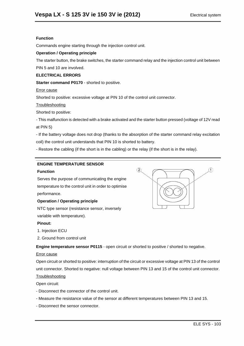
Function
Commands engine starting through the injection control unit.
Operation / Operating principle
The starter button, the brake switches, the starter command relay and the injection control unit between
PIN 5 and 10 are involved.
ELECTRICAL ERRORS
Starter command P0170 - shorted to positive.
Error cause
Shorted to positive: excessive voltage at PIN 10 of the control unit connector.
Troubleshooting
Shorted to positive:
- This malfunction is detected with a brake activated and the starter button pressed (voltage of 12V read
at PIN 5)
- If the battery voltage does not drop (thanks to the absorption of the starter command relay excitation
coil) the control unit understands that PIN 10 is shorted to battery.
- Restore the cabling (if the short is in the cabling) or the relay (if the short is in the relay).
ENGINE TEMPERATURE SENSOR
Function
Serves the purpose of communicating the engine
temperature to the control unit in order to optimise
performance.
Operation / Operating principle
NTC type sensor (resistance sensor, inversely
variable with temperature).
Pinout:
1. Injection ECU
2. Ground from control unit
Engine temperature sensor P0115 - open circuit or shorted to positive / shorted to negative.
Error cause
Open circuit or shorted to positive: interruption of the circuit or excessive voltage at PIN 13 of the control
unit connector. Shorted to negative: null voltage between PIN 13 and 15 of the control unit connector.
Troubleshooting
Open circuit:
- Disconnect the connector of the control unit.
- Measure the resistance value of the sensor at different temperatures between PIN 13 and 15.
- Disconnect the sensor connector.
Vespa LX - S 125 3V ie 150 3V ie (2012) Electrical system
ELE SYS - 103
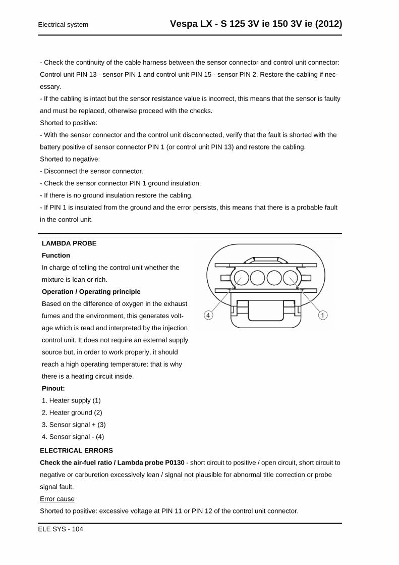
- Check the continuity of the cable harness between the sensor connector and control unit connector:
Control unit PIN 13 - sensor PIN 1 and control unit PIN 15 - sensor PIN 2. Restore the cabling if nec-
essary.
- If the cabling is intact but the sensor resistance value is incorrect, this means that the sensor is faulty
and must be replaced, otherwise proceed with the checks.
Shorted to positive:
- With the sensor connector and the control unit disconnected, verify that the fault is shorted with the
battery positive of sensor connector PIN 1 (or control unit PIN 13) and restore the cabling.
Shorted to negative:
- Disconnect the sensor connector.
- Check the sensor connector PIN 1 ground insulation.
- If there is no ground insulation restore the cabling.
- If PIN 1 is insulated from the ground and the error persists, this means that there is a probable fault
in the control unit.
LAMBDA PROBE
Function
In charge of telling the control unit whether the
mixture is lean or rich.
Operation / Operating principle
Based on the difference of oxygen in the exhaust
fumes and the environment, this generates volt-
age which is read and interpreted by the injection
control unit. It does not require an external supply
source but, in order to work properly, it should
reach a high operating temperature: that is why
there is a heating circuit inside.
Pinout:
1. Heater supply (1)
2. Heater ground (2)
3. Sensor signal + (3)
4. Sensor signal - (4)
ELECTRICAL ERRORS
Check the air-fuel ratio / Lambda probe P0130 - short circuit to positive / open circuit, short circuit to
negative or carburetion excessively lean / signal not plausible for abnormal title correction or probe
signal fault.
Error cause
Shorted to positive: excessive voltage at PIN 11 or PIN 12 of the control unit connector.
Electrical system Vespa LX - S 125 3V ie 150 3V ie (2012)
ELE SYS - 104
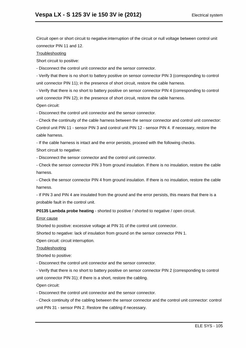
Circuit open or short circuit to negative:interruption of the circuit or null voltage between control unit
connector PIN 11 and 12.
Troubleshooting
Short circuit to positive:
- Disconnect the control unit connector and the sensor connector.
- Verify that there is no short to battery positive on sensor connector PIN 3 (corresponding to control
unit connector PIN 11); in the presence of short circuit, restore the cable harness.
- Verify that there is no short to battery positive on sensor connector PIN 4 (corresponding to control
unit connector PIN 12); in the presence of short circuit, restore the cable harness.
Open circuit:
- Disconnect the control unit connector and the sensor connector.
- Check the continuity of the cable harness between the sensor connector and control unit connector:
Control unit PIN 11 - sensor PIN 3 and control unit PIN 12 - sensor PIN 4. If necessary, restore the
cable harness.
- If the cable harness is intact and the error persists, proceed with the following checks.
Short circuit to negative:
- Disconnect the sensor connector and the control unit connector.
- Check the sensor connector PIN 3 from ground insulation. If there is no insulation, restore the cable
harness.
- Check the sensor connector PIN 4 from ground insulation. If there is no insulation, restore the cable
harness.
- If PIN 3 and PIN 4 are insulated from the ground and the error persists, this means that there is a
probable fault in the control unit.
P0135 Lambda probe heating - shorted to positive / shorted to negative / open circuit.
Error cause
Shorted to positive: excessive voltage at PIN 31 of the control unit connector.
Shorted to negative: lack of insulation from ground on the sensor connector PIN 1.
Open circuit: circuit interruption.
Troubleshooting
Shorted to positive:
- Disconnect the control unit connector and the sensor connector.
- Verify that there is no short to battery positive on sensor connector PIN 2 (corresponding to control
unit connector PIN 31); if there is a short, restore the cabling.
Open circuit:
- Disconnect the control unit connector and the sensor connector.
- Check continuity of the cabling between the sensor connector and the control unit connector: control
unit PIN 31 - sensor PIN 2. Restore the cabling if necessary.
Vespa LX - S 125 3V ie 150 3V ie (2012) Electrical system
ELE SYS - 105
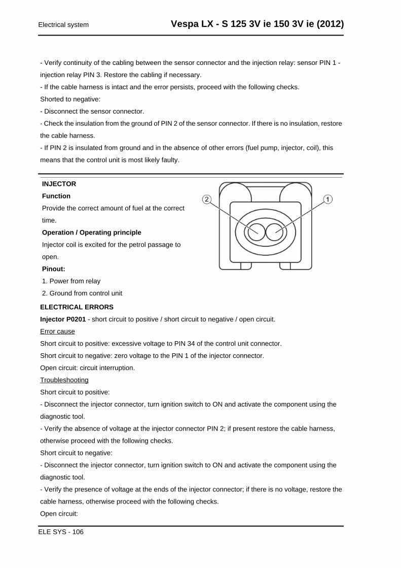
- Verify continuity of the cabling between the sensor connector and the injection relay: sensor PIN 1 -
injection relay PIN 3. Restore the cabling if necessary.
- If the cable harness is intact and the error persists, proceed with the following checks.
Shorted to negative:
- Disconnect the sensor connector.
- Check the insulation from the ground of PIN 2 of the sensor connector. If there is no insulation, restore
the cable harness.
- If PIN 2 is insulated from ground and in the absence of other errors (fuel pump, injector, coil), this
means that the control unit is most likely faulty.
INJECTOR
Function
Provide the correct amount of fuel at the correct
time.
Operation / Operating principle
Injector coil is excited for the petrol passage to
open.
Pinout:
1. Power from relay
2. Ground from control unit
ELECTRICAL ERRORS
Injector P0201 - short circuit to positive / short circuit to negative / open circuit.
Error cause
Short circuit to positive: excessive voltage to PIN 34 of the control unit connector.
Short circuit to negative: zero voltage to the PIN 1 of the injector connector.
Open circuit: circuit interruption.
Troubleshooting
Short circuit to positive:
- Disconnect the injector connector, turn ignition switch to ON and activate the component using the
diagnostic tool.
- Verify the absence of voltage at the injector connector PIN 2; if present restore the cable harness,
otherwise proceed with the following checks.
Short circuit to negative:
- Disconnect the injector connector, turn ignition switch to ON and activate the component using the
diagnostic tool.
- Verify the presence of voltage at the ends of the injector connector; if there is no voltage, restore the
cable harness, otherwise proceed with the following checks.
Open circuit:
Electrical system Vespa LX - S 125 3V ie 150 3V ie (2012)
ELE SYS - 106
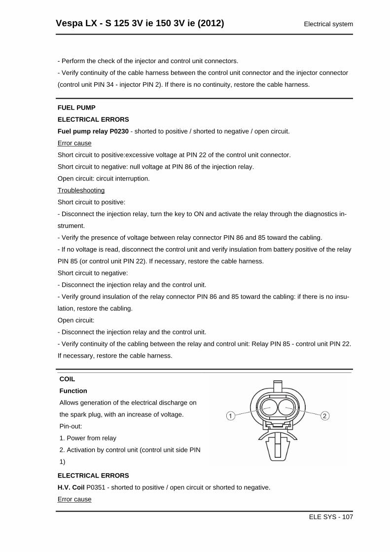
- Perform the check of the injector and control unit connectors.
- Verify continuity of the cable harness between the control unit connector and the injector connector
(control unit PIN 34 - injector PIN 2). If there is no continuity, restore the cable harness.
FUEL PUMP
ELECTRICAL ERRORS
Fuel pump relay P0230 - shorted to positive / shorted to negative / open circuit.
Error cause
Short circuit to positive:excessive voltage at PIN 22 of the control unit connector.
Short circuit to negative: null voltage at PIN 86 of the injection relay.
Open circuit: circuit interruption.
Troubleshooting
Short circuit to positive:
- Disconnect the injection relay, turn the key to ON and activate the relay through the diagnostics in-
strument.
- Verify the presence of voltage between relay connector PIN 86 and 85 toward the cabling.
- If no voltage is read, disconnect the control unit and verify insulation from battery positive of the relay
PIN 85 (or control unit PIN 22). If necessary, restore the cable harness.
Short circuit to negative:
- Disconnect the injection relay and the control unit.
- Verify ground insulation of the relay connector PIN 86 and 85 toward the cabling: if there is no insu-
lation, restore the cabling.
Open circuit:
- Disconnect the injection relay and the control unit.
- Verify continuity of the cabling between the relay and control unit: Relay PIN 85 - control unit PIN 22.
If necessary, restore the cable harness.
COIL
Function
Allows generation of the electrical discharge on
the spark plug, with an increase of voltage.
Pin-out:
1. Power from relay
2. Activation by control unit (control unit side PIN
1)
ELECTRICAL ERRORS
H.V. Coil P0351 - shorted to positive / open circuit or shorted to negative.
Error cause
Vespa LX - S 125 3V ie 150 3V ie (2012) Electrical system
ELE SYS - 107
Short circuit to positive:excessive voltage at PIN 1 of the control unit connector.
Circuit open or shorted to negative: interruption of the circuit or null voltage at PIN 1 of the control unit
connector.
Troubleshooting
Short circuit to positive:
- Disconnect the coil connector, turn the key to ON and activate the component through the diagnostics
instrument.
- Verify the presence of voltage on the coil connector PIN 2: if present, restore the cabling, otherwise
replace the coil.
Open circuit:
- Carry out the check procedure of the coil and control unit connectors.
- Verify continuity of the cabling between the coil and control unit: Coil PIN 2 - control unit PIN 1. If there
is no continuity, restore the cable harness.
- Verify, with the key turned ON, the presence of voltage on the coil connector PIN 1. If no voltage is
detected, check that the cable harness between the coil and injection relay is not interrupted: Coil PIN
1 - relay PIN 30.
- If the above tests provided a positive result, the coil should be replaced.
Short circuit to negative:
- Disconnect the control unit connector and the coil connector.
- Verify the coil connector PIN 2 ground insulation (or control unit connector PIN 1). If necessary, restore
the cable harness.
Electrical system Vespa LX - S 125 3V ie 150 3V ie (2012)
ELE SYS - 108
INDEX OF TOPICS
ENGINE FROM VEHICLE ENG VE
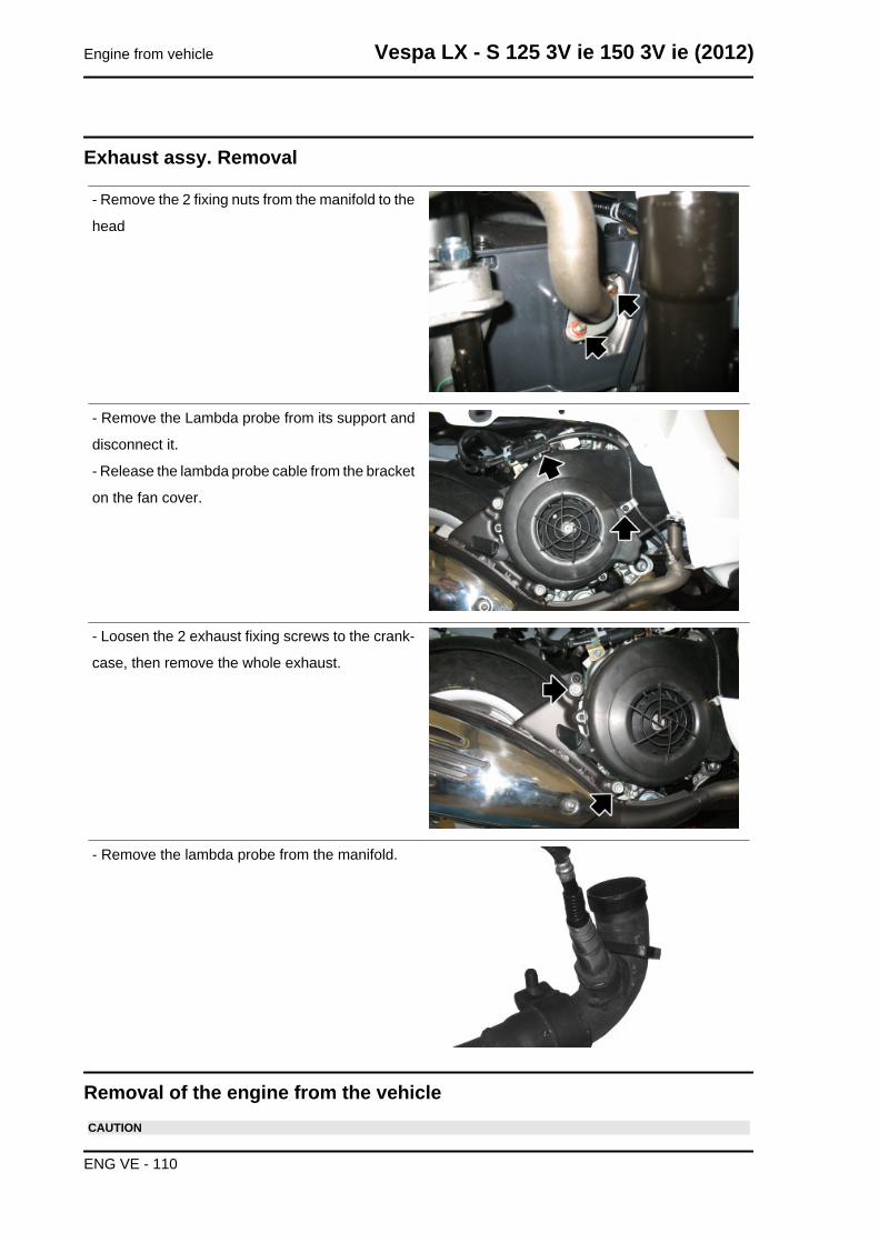
Exhaust assy. Removal
- Remove the 2 fixing nuts from the manifold to the
head
- Remove the Lambda probe from its support and
disconnect it.
- Release the lambda probe cable from the bracket
on the fan cover.
- Loosen the 2 exhaust fixing screws to the crank-
case, then remove the whole exhaust.
- Remove the lambda probe from the manifold.
Removal of the engine from the vehicleCAUTION
Engine from vehicle Vespa LX - S 125 3V ie 150 3V ie (2012)
ENG VE - 110
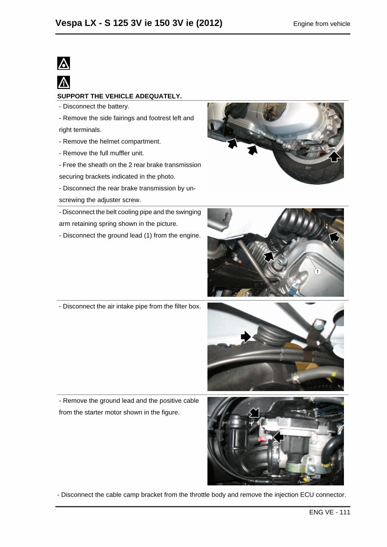
SUPPORT THE VEHICLE ADEQUATELY.- Disconnect the battery.
- Remove the side fairings and footrest left and
right terminals.
- Remove the helmet compartment.
- Remove the full muffler unit.
- Free the sheath on the 2 rear brake transmission
securing brackets indicated in the photo.
- Disconnect the rear brake transmission by un-
screwing the adjuster screw.
- Disconnect the belt cooling pipe and the swinging
arm retaining spring shown in the picture.
- Disconnect the ground lead (1) from the engine.
- Disconnect the air intake pipe from the filter box.
- Remove the ground lead and the positive cable
from the starter motor shown in the figure.
- Disconnect the cable camp bracket from the throttle body and remove the injection ECU connector.
Vespa LX - S 125 3V ie 150 3V ie (2012) Engine from vehicle
ENG VE - 111
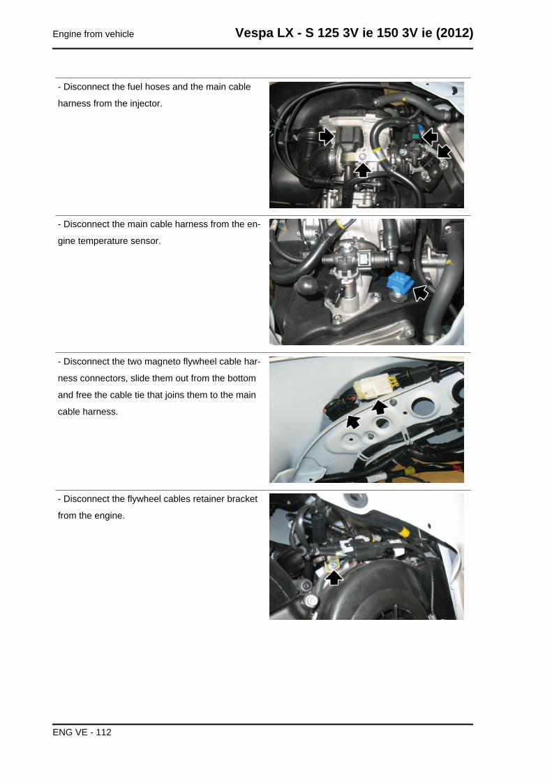
- Disconnect the fuel hoses and the main cable
harness from the injector.
- Disconnect the main cable harness from the en-
gine temperature sensor.
- Disconnect the two magneto flywheel cable har-
ness connectors, slide them out from the bottom
and free the cable tie that joins them to the main
cable harness.
- Disconnect the flywheel cables retainer bracket
from the engine.
Engine from vehicle Vespa LX - S 125 3V ie 150 3V ie (2012)
ENG VE - 112
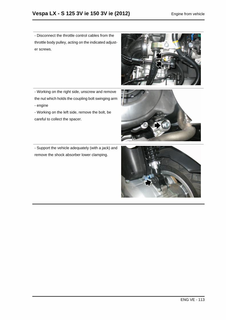
- Disconnect the throttle control cables from the
throttle body pulley, acting on the indicated adjust-
er screws.
- Working on the right side, unscrew and remove
the nut which holds the coupling bolt swinging arm
- engine
- Working on the left side, remove the bolt, be
careful to collect the spacer.
- Support the vehicle adequately (with a jack) and
remove the shock absorber lower clamping.
Vespa LX - S 125 3V ie 150 3V ie (2012) Engine from vehicle
ENG VE - 113
INDEX OF TOPICS
ENGINE ENG
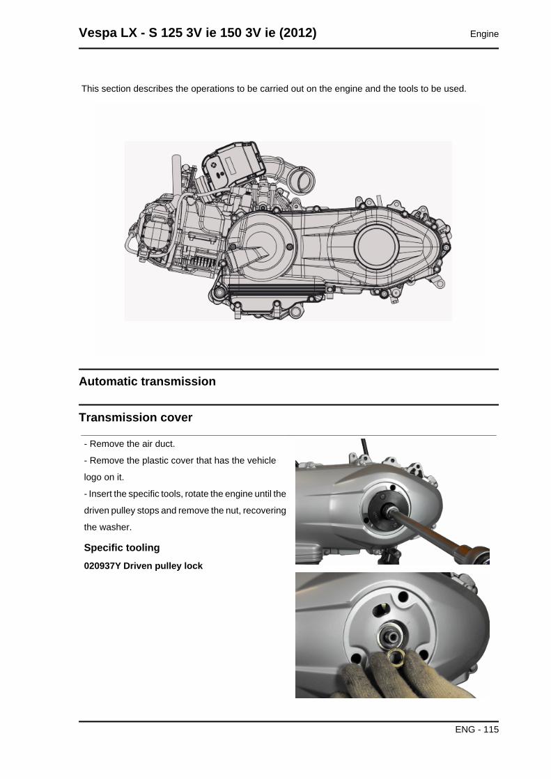
This section describes the operations to be carried out on the engine and the tools to be used.
Automatic transmission
Transmission cover
- Remove the air duct.
- Remove the plastic cover that has the vehicle
logo on it.
- Insert the specific tools, rotate the engine until the
driven pulley stops and remove the nut, recovering
the washer.
Specific tooling020937Y Driven pulley lock
Vespa LX - S 125 3V ie 150 3V ie (2012) Engine
ENG - 115
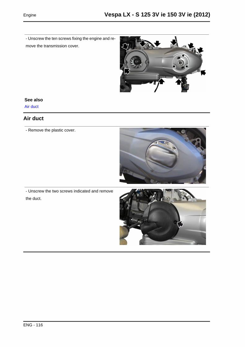
- Unscrew the ten screws fixing the engine and re-
move the transmission cover.
See alsoAir duct
Air duct
- Remove the plastic cover.
- Unscrew the two screws indicated and remove
the duct.
Engine Vespa LX - S 125 3V ie 150 3V ie (2012)
ENG - 116
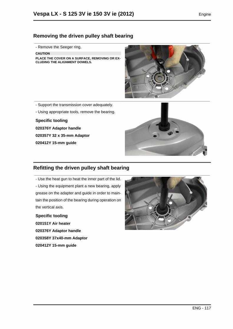
Removing the driven pulley shaft bearing
- Remove the Seeger ring.CAUTIONPLACE THE COVER ON A SURFACE, REMOVING OR EX-CLUDING THE ALIGNMENT DOWELS.
- Support the transmission cover adequately.
- Using appropriate tools, remove the bearing.
Specific tooling020376Y Adaptor handle
020357Y 32 x 35-mm Adaptor
020412Y 15-mm guide
Refitting the driven pulley shaft bearing
- Use the heat gun to heat the inner part of the lid.
- Using the equipment plant a new bearing, apply
grease on the adapter and guide in order to main-
tain the position of the bearing during operation on
the vertical axis.
Specific tooling020151Y Air heater
020376Y Adaptor handle
020358Y 37x40-mm Adaptor
020412Y 15-mm guide
Vespa LX - S 125 3V ie 150 3V ie (2012) Engine
ENG - 117
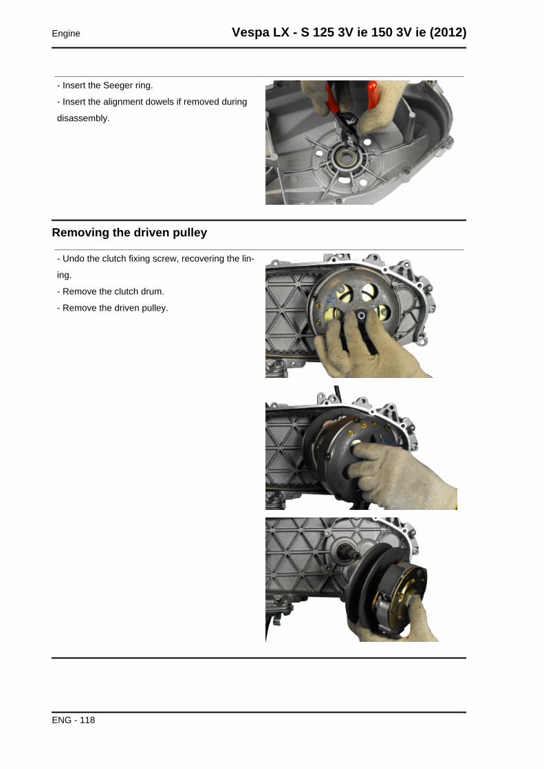
- Insert the Seeger ring.
- Insert the alignment dowels if removed during
disassembly.
Removing the driven pulley
- Undo the clutch fixing screw, recovering the lin-
ing.
- Remove the clutch drum.
- Remove the driven pulley.
Engine Vespa LX - S 125 3V ie 150 3V ie (2012)
ENG - 118
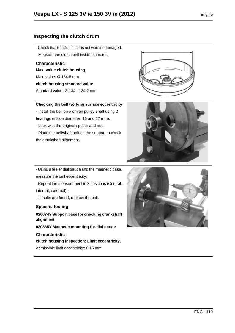
Inspecting the clutch drum
- Check that the clutch bell is not worn or damaged.
- Measure the clutch bell inside diameter.
CharacteristicMax. value clutch housingMax. value: Ø 134.5 mm
clutch housing standard valueStandard value: Ø 134 - 134.2 mm
Checking the bell working surface eccentricity
- Install the bell on a driven pulley shaft using 2
bearings (inside diameter: 15 and 17 mm).
- Lock with the original spacer and nut.
- Place the bell/shaft unit on the support to check
the crankshaft alignment.
- Using a feeler dial gauge and the magnetic base,
measure the bell eccentricity.
- Repeat the measurement in 3 positions (Central,
internal, external).
- If faults are found, replace the bell.
Specific tooling020074Y Support base for checking crankshaftalignment
020335Y Magnetic mounting for dial gauge
Characteristicclutch housing inspection: Limit eccentricity.Admissible limit eccentricity: 0.15 mm
Vespa LX - S 125 3V ie 150 3V ie (2012) Engine
ENG - 119
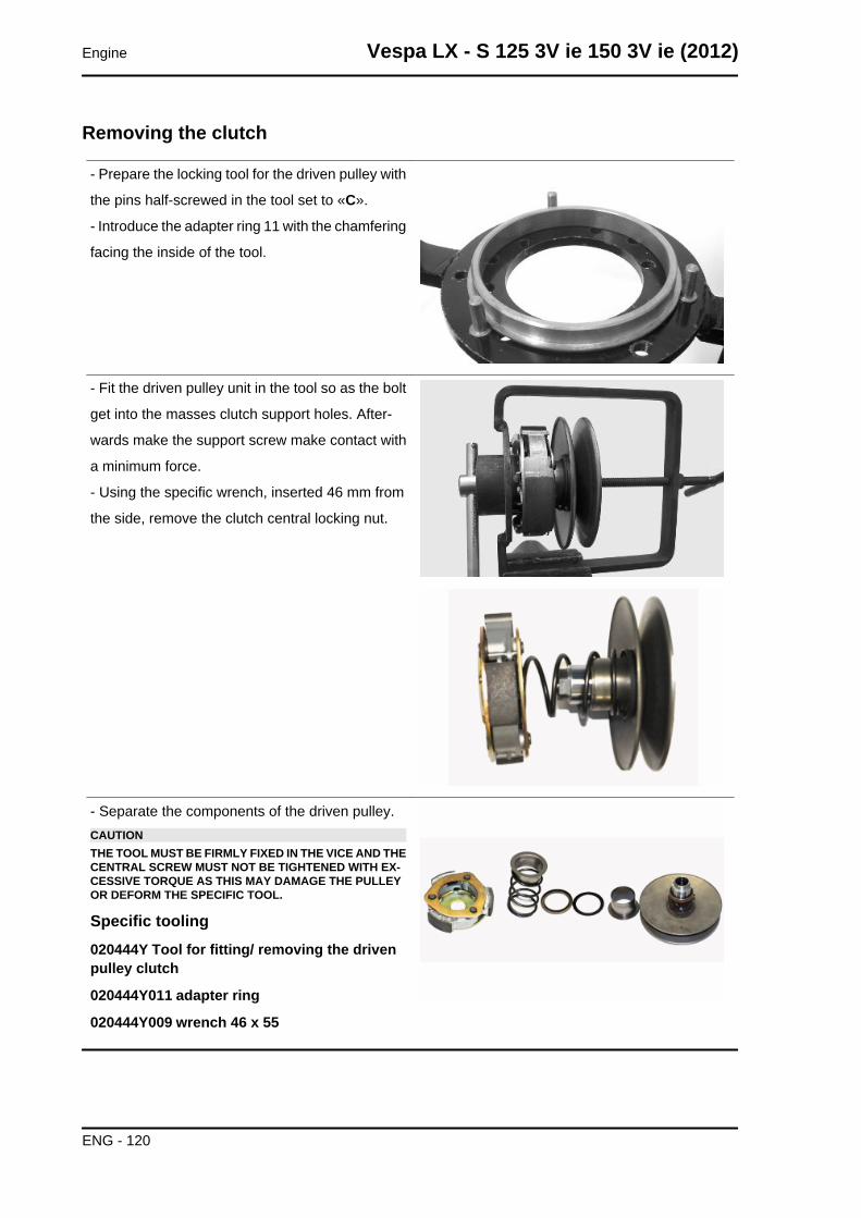
Removing the clutch
- Prepare the locking tool for the driven pulley with
the pins half-screwed in the tool set to «C».
- Introduce the adapter ring 11 with the chamfering
facing the inside of the tool.
- Fit the driven pulley unit in the tool so as the bolt
get into the masses clutch support holes. After-
wards make the support screw make contact with
a minimum force.
- Using the specific wrench, inserted 46 mm from
the side, remove the clutch central locking nut.
- Separate the components of the driven pulley.CAUTIONTHE TOOL MUST BE FIRMLY FIXED IN THE VICE AND THECENTRAL SCREW MUST NOT BE TIGHTENED WITH EX-CESSIVE TORQUE AS THIS MAY DAMAGE THE PULLEYOR DEFORM THE SPECIFIC TOOL.
Specific tooling020444Y Tool for fitting/ removing the drivenpulley clutch
020444Y011 adapter ring
020444Y009 wrench 46 x 55
Engine Vespa LX - S 125 3V ie 150 3V ie (2012)
ENG - 120
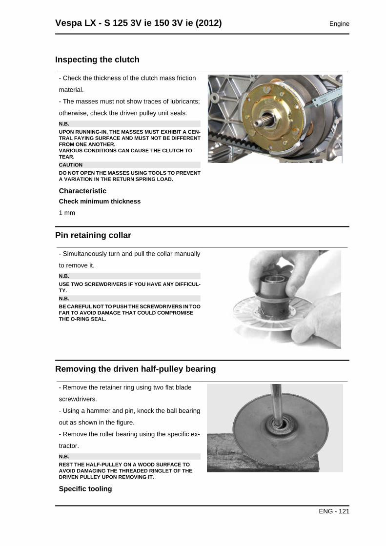
Inspecting the clutch
- Check the thickness of the clutch mass friction
material.
- The masses must not show traces of lubricants;
otherwise, check the driven pulley unit seals.N.B.UPON RUNNING-IN, THE MASSES MUST EXHIBIT A CEN-TRAL FAYING SURFACE AND MUST NOT BE DIFFERENTFROM ONE ANOTHER.VARIOUS CONDITIONS CAN CAUSE THE CLUTCH TOTEAR.CAUTIONDO NOT OPEN THE MASSES USING TOOLS TO PREVENTA VARIATION IN THE RETURN SPRING LOAD.
CharacteristicCheck minimum thickness1 mm
Pin retaining collar
- Simultaneously turn and pull the collar manually
to remove it.N.B.USE TWO SCREWDRIVERS IF YOU HAVE ANY DIFFICUL-TY.N.B.BE CAREFUL NOT TO PUSH THE SCREWDRIVERS IN TOOFAR TO AVOID DAMAGE THAT COULD COMPROMISETHE O-RING SEAL.
Removing the driven half-pulley bearing
- Remove the retainer ring using two flat blade
screwdrivers.
- Using a hammer and pin, knock the ball bearing
out as shown in the figure.
- Remove the roller bearing using the specific ex-
tractor.N.B.REST THE HALF-PULLEY ON A WOOD SURFACE TOAVOID DAMAGING THE THREADED RINGLET OF THEDRIVEN PULLEY UPON REMOVING IT.
Specific tooling
Vespa LX - S 125 3V ie 150 3V ie (2012) Engine
ENG - 121
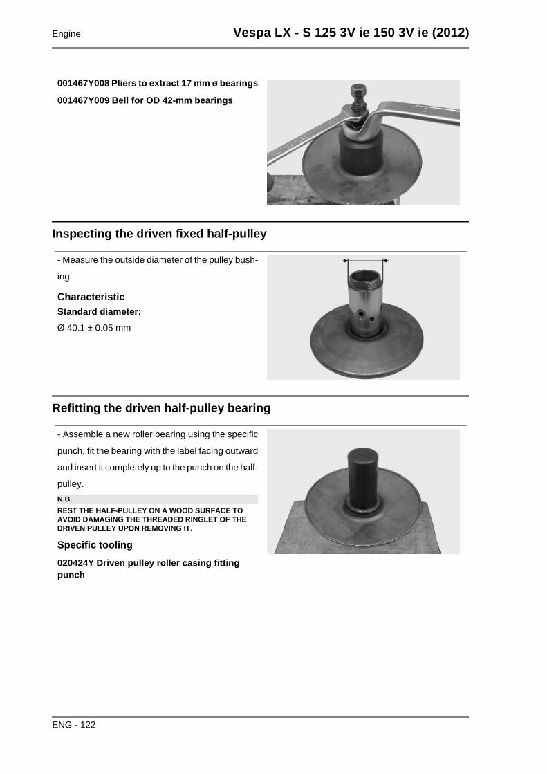
001467Y008 Pliers to extract 17 mm ø bearings
001467Y009 Bell for OD 42-mm bearings
Inspecting the driven fixed half-pulley
- Measure the outside diameter of the pulley bush-
ing.
CharacteristicStandard diameter:Ø 40.1 ± 0.05 mm
Refitting the driven half-pulley bearing
- Assemble a new roller bearing using the specific
punch, fit the bearing with the label facing outward
and insert it completely up to the punch on the half-
pulley.N.B.REST THE HALF-PULLEY ON A WOOD SURFACE TOAVOID DAMAGING THE THREADED RINGLET OF THEDRIVEN PULLEY UPON REMOVING IT.
Specific tooling020424Y Driven pulley roller casing fittingpunch
Engine Vespa LX - S 125 3V ie 150 3V ie (2012)
ENG - 122
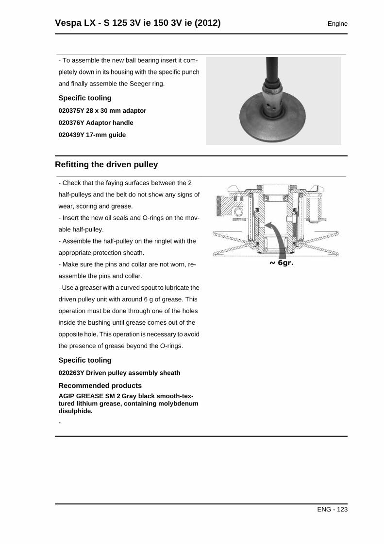
- To assemble the new ball bearing insert it com-
pletely down in its housing with the specific punch
and finally assemble the Seeger ring.
Specific tooling020375Y 28 x 30 mm adaptor
020376Y Adaptor handle
020439Y 17-mm guide
Refitting the driven pulley
- Check that the faying surfaces between the 2
half-pulleys and the belt do not show any signs of
wear, scoring and grease.
- Insert the new oil seals and O-rings on the mov-
able half-pulley.
- Assemble the half-pulley on the ringlet with the
appropriate protection sheath.
- Make sure the pins and collar are not worn, re-
assemble the pins and collar.
- Use a greaser with a curved spout to lubricate the
driven pulley unit with around 6 g of grease. This
operation must be done through one of the holes
inside the bushing until grease comes out of the
opposite hole. This operation is necessary to avoid
the presence of grease beyond the O-rings.
Specific tooling020263Y Driven pulley assembly sheath
Recommended productsAGIP GREASE SM 2 Gray black smooth-tex-tured lithium grease, containing molybdenumdisulphide.-
Vespa LX - S 125 3V ie 150 3V ie (2012) Engine
ENG - 123
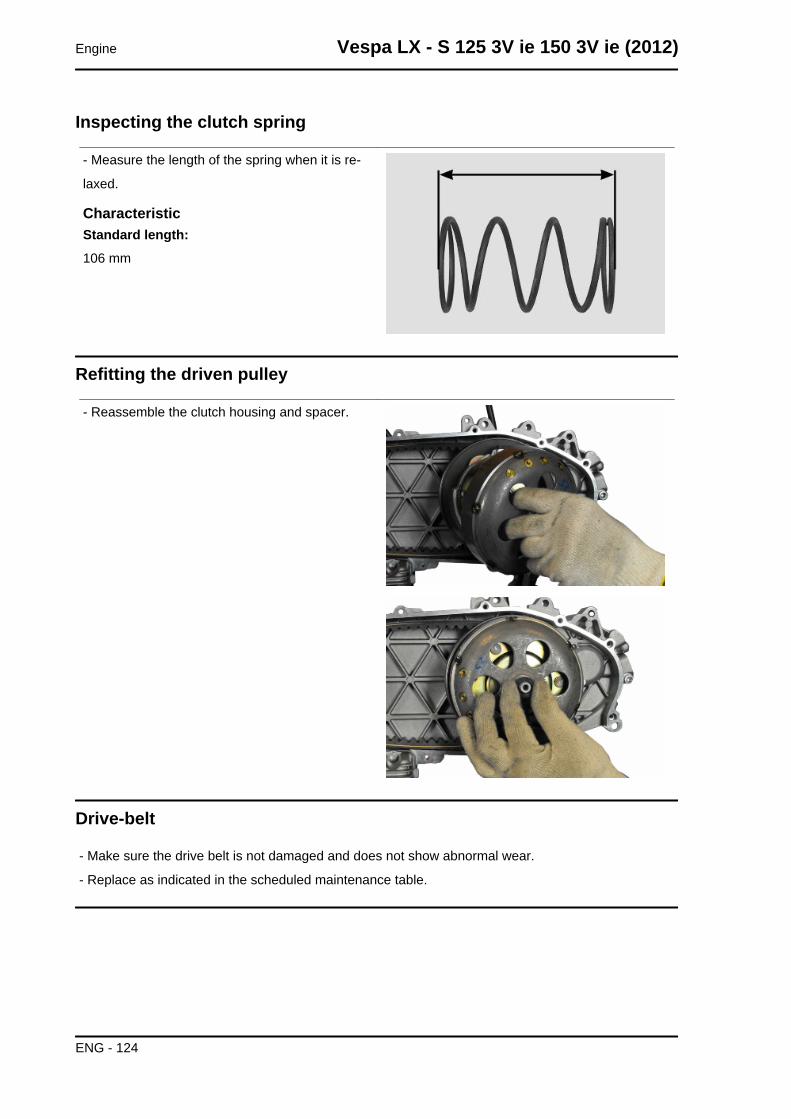
Inspecting the clutch spring
- Measure the length of the spring when it is re-
laxed.
CharacteristicStandard length:106 mm
Refitting the driven pulley
- Reassemble the clutch housing and spacer.
Drive-belt
- Make sure the drive belt is not damaged and does not show abnormal wear.
- Replace as indicated in the scheduled maintenance table.
Engine Vespa LX - S 125 3V ie 150 3V ie (2012)
ENG - 124
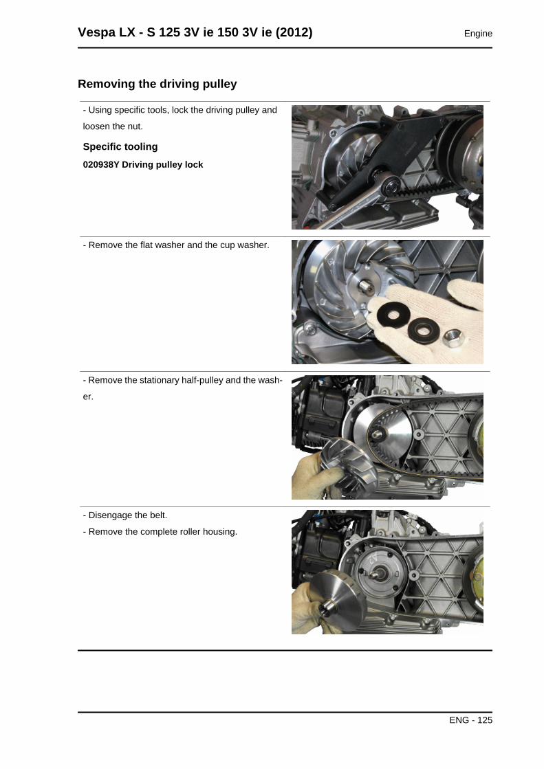
Removing the driving pulley
- Using specific tools, lock the driving pulley and
loosen the nut.
Specific tooling020938Y Driving pulley lock
- Remove the flat washer and the cup washer.
- Remove the stationary half-pulley and the wash-
er.
- Disengage the belt.
- Remove the complete roller housing.
Vespa LX - S 125 3V ie 150 3V ie (2012) Engine
ENG - 125
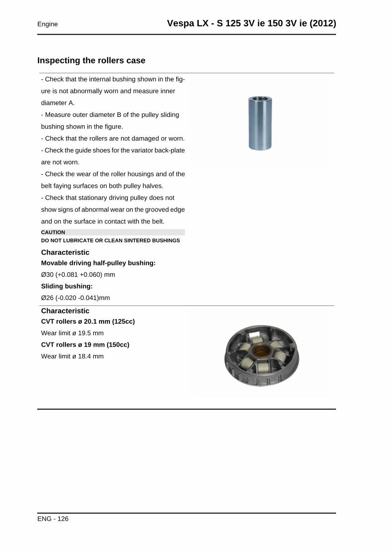
Inspecting the rollers case
- Check that the internal bushing shown in the fig-
ure is not abnormally worn and measure inner
diameter A.
- Measure outer diameter B of the pulley sliding
bushing shown in the figure.
- Check that the rollers are not damaged or worn.
- Check the guide shoes for the variator back-plate
are not worn.
- Check the wear of the roller housings and of the
belt faying surfaces on both pulley halves.
- Check that stationary driving pulley does not
show signs of abnormal wear on the grooved edge
and on the surface in contact with the belt.CAUTIONDO NOT LUBRICATE OR CLEAN SINTERED BUSHINGS
CharacteristicMovable driving half-pulley bushing:Ø30 (+0.081 +0.060) mm
Sliding bushing:Ø26 (-0.020 -0.041)mm
CharacteristicCVT rollers ø 20.1 mm (125cc)Wear limit ø 19.5 mm
CVT rollers ø 19 mm (150cc)Wear limit ø 18.4 mm
Engine Vespa LX - S 125 3V ie 150 3V ie (2012)
ENG - 126
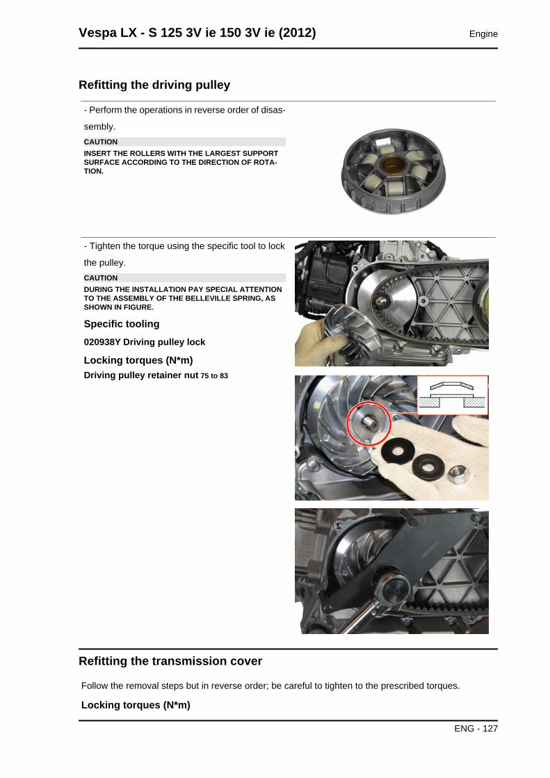
Refitting the driving pulley
- Perform the operations in reverse order of disas-
sembly.CAUTIONINSERT THE ROLLERS WITH THE LARGEST SUPPORTSURFACE ACCORDING TO THE DIRECTION OF ROTA-TION.
- Tighten the torque using the specific tool to lock
the pulley.CAUTIONDURING THE INSTALLATION PAY SPECIAL ATTENTIONTO THE ASSEMBLY OF THE BELLEVILLE SPRING, ASSHOWN IN FIGURE.
Specific tooling020938Y Driving pulley lock
Locking torques (N*m)Driving pulley retainer nut 75 to 83
Refitting the transmission cover
Follow the removal steps but in reverse order; be careful to tighten to the prescribed torques.
Locking torques (N*m)
Vespa LX - S 125 3V ie 150 3V ie (2012) Engine
ENG - 127
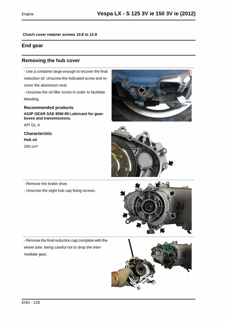
Clutch cover retainer screws 10.8 to 12.8
End gear
Removing the hub cover
- Use a container large enough to recover the final
reduction oil. Unscrew the indicated screw and re-
cover the aluminium seal.
- Unscrew the oil filler screw in order to facilitate
bleeding.
Recommended productsAGIP GEAR SAE 80W-90 Lubricant for gear-boxes and transmissions.API GL-4
CharacteristicHub oil200 cm³
- Remove the brake shoe.
- Unscrew the eight hub cap fixing screws.
- Remove the final reduction cap complete with the
wheel axle, being careful not to drop the inter-
mediate gear.
Engine Vespa LX - S 125 3V ie 150 3V ie (2012)
ENG - 128
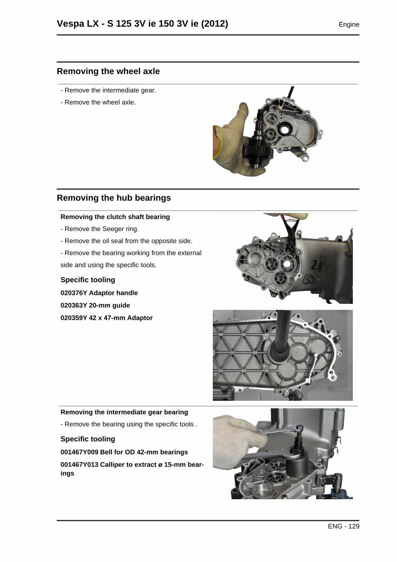
Removing the wheel axle
- Remove the intermediate gear.
- Remove the wheel axle.
Removing the hub bearings
Removing the clutch shaft bearing
- Remove the Seeger ring.
- Remove the oil seal from the opposite side.
- Remove the bearing working from the external
side and using the specific tools.
Specific tooling020376Y Adaptor handle
020363Y 20-mm guide
020359Y 42 x 47-mm Adaptor
Removing the intermediate gear bearing
- Remove the bearing using the specific tools .
Specific tooling001467Y009 Bell for OD 42-mm bearings
001467Y013 Calliper to extract ø 15-mm bear-ings
Vespa LX - S 125 3V ie 150 3V ie (2012) Engine
ENG - 129
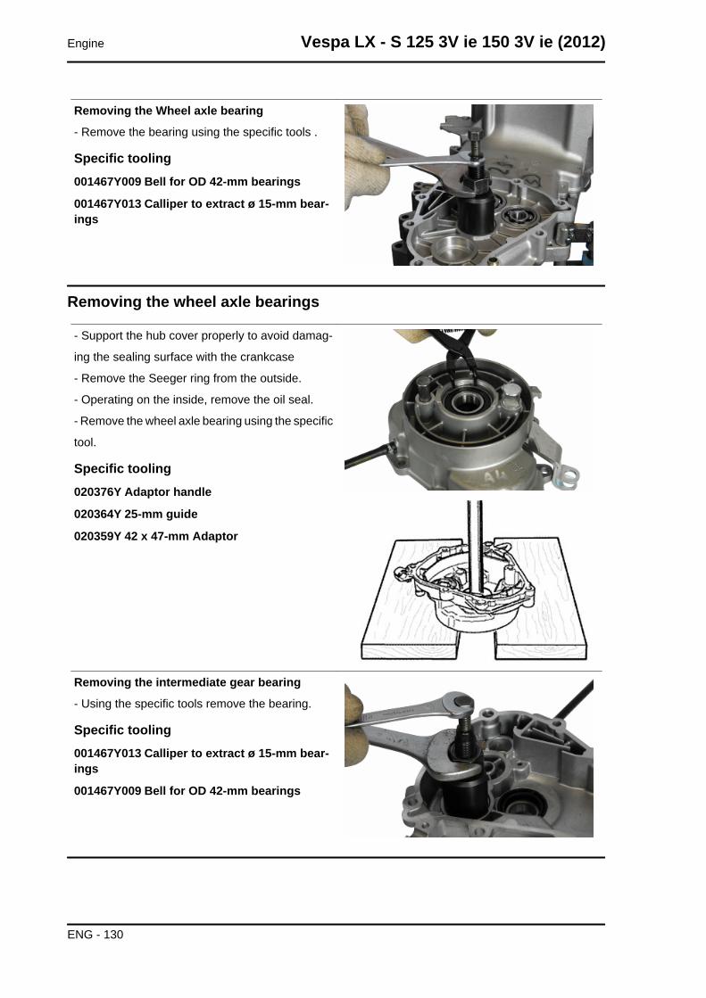
Removing the Wheel axle bearing
- Remove the bearing using the specific tools .
Specific tooling001467Y009 Bell for OD 42-mm bearings
001467Y013 Calliper to extract ø 15-mm bear-ings
Removing the wheel axle bearings
- Support the hub cover properly to avoid damag-
ing the sealing surface with the crankcase
- Remove the Seeger ring from the outside.
- Operating on the inside, remove the oil seal.
- Remove the wheel axle bearing using the specific
tool.
Specific tooling020376Y Adaptor handle
020364Y 25-mm guide
020359Y 42 x 47-mm Adaptor
Removing the intermediate gear bearing
- Using the specific tools remove the bearing.
Specific tooling001467Y013 Calliper to extract ø 15-mm bear-ings
001467Y009 Bell for OD 42-mm bearings
Engine Vespa LX - S 125 3V ie 150 3V ie (2012)
ENG - 130
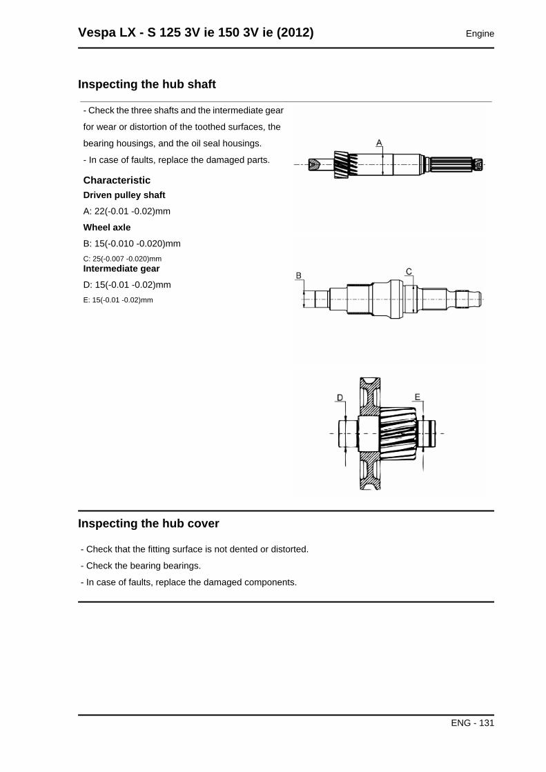
Inspecting the hub shaft
- Check the three shafts and the intermediate gear
for wear or distortion of the toothed surfaces, the
bearing housings, and the oil seal housings.
- In case of faults, replace the damaged parts.
CharacteristicDriven pulley shaftA: 22(-0.01 -0.02)mm
Wheel axleB: 15(-0.010 -0.020)mmC: 25(-0.007 -0.020)mmIntermediate gearD: 15(-0.01 -0.02)mmE: 15(-0.01 -0.02)mm
Inspecting the hub cover
- Check that the fitting surface is not dented or distorted.
- Check the bearing bearings.
- In case of faults, replace the damaged components.
Vespa LX - S 125 3V ie 150 3V ie (2012) Engine
ENG - 131
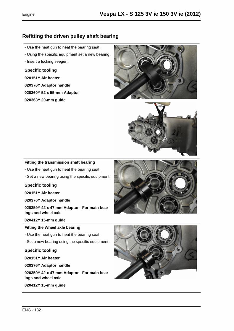
Refitting the driven pulley shaft bearing
- Use the heat gun to heat the bearing seat.
- Using the specific equipment set a new bearing.
- Insert a locking seeger.
Specific tooling020151Y Air heater
020376Y Adaptor handle
020360Y 52 x 55-mm Adaptor
020363Y 20-mm guide
Fitting the transmission shaft bearing
- Use the heat gun to heat the bearing seat.
- Set a new bearing using the specific equipment.
Specific tooling020151Y Air heater
020376Y Adaptor handle
020359Y 42 x 47 mm Adaptor - For main bear-ings and wheel axle
020412Y 15-mm guide
Fitting the Wheel axle bearing
- Use the heat gun to heat the bearing seat.
- Set a new bearing using the specific equipment .
Specific tooling020151Y Air heater
020376Y Adaptor handle
020359Y 42 x 47 mm Adaptor - For main bear-ings and wheel axle
020412Y 15-mm guide
Engine Vespa LX - S 125 3V ie 150 3V ie (2012)
ENG - 132
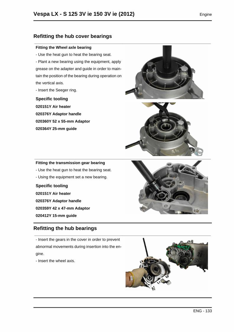
Refitting the hub cover bearings
Fitting the Wheel axle bearing
- Use the heat gun to heat the bearing seat.
- Plant a new bearing using the equipment, apply
grease on the adapter and guide in order to main-
tain the position of the bearing during operation on
the vertical axis.
- Insert the Seeger ring.
Specific tooling020151Y Air heater
020376Y Adaptor handle
020360Y 52 x 55-mm Adaptor
020364Y 25-mm guide
Fitting the transmission gear bearing
- Use the heat gun to heat the bearing seat.
- Using the equipment set a new bearing.
Specific tooling020151Y Air heater
020376Y Adaptor handle
020359Y 42 x 47-mm Adaptor
020412Y 15-mm guide
Refitting the hub bearings
- Insert the gears in the cover in order to prevent
abnormal movements during insertion into the en-
gine.
- Insert the wheel axis.
Vespa LX - S 125 3V ie 150 3V ie (2012) Engine
ENG - 133
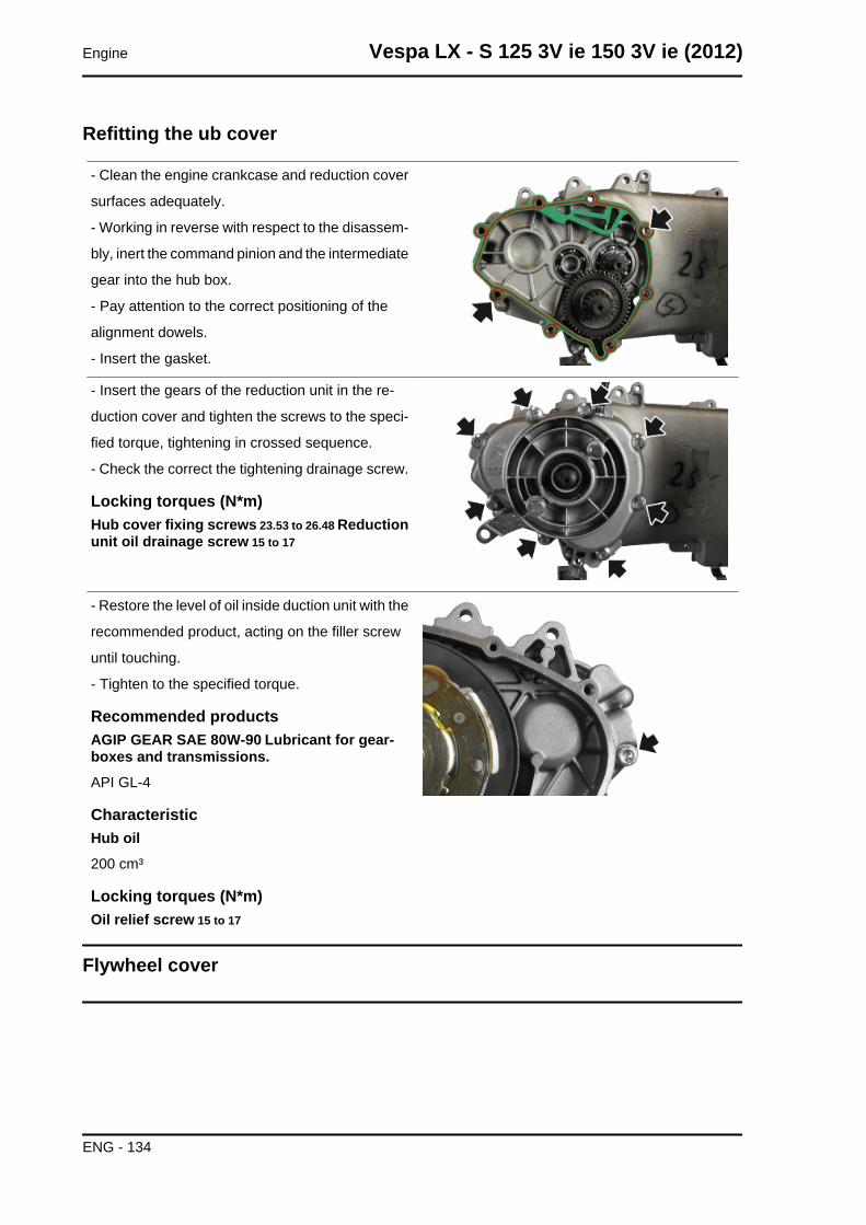
Refitting the ub cover
- Clean the engine crankcase and reduction cover
surfaces adequately.
- Working in reverse with respect to the disassem-
bly, inert the command pinion and the intermediate
gear into the hub box.
- Pay attention to the correct positioning of the
alignment dowels.
- Insert the gasket.
- Insert the gears of the reduction unit in the re-
duction cover and tighten the screws to the speci-
fied torque, tightening in crossed sequence.
- Check the correct the tightening drainage screw.
Locking torques (N*m)Hub cover fixing screws 23.53 to 26.48 Reductionunit oil drainage screw 15 to 17
- Restore the level of oil inside duction unit with the
recommended product, acting on the filler screw
until touching.
- Tighten to the specified torque.
Recommended productsAGIP GEAR SAE 80W-90 Lubricant for gear-boxes and transmissions.API GL-4
CharacteristicHub oil200 cm³
Locking torques (N*m)Oil relief screw 15 to 17
Flywheel cover
Engine Vespa LX - S 125 3V ie 150 3V ie (2012)
ENG - 134
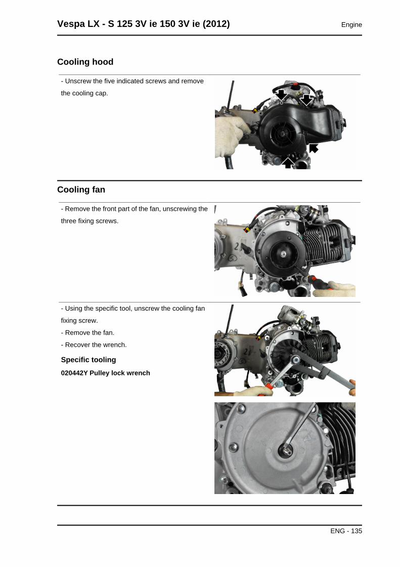
Cooling hood
- Unscrew the five indicated screws and remove
the cooling cap.
Cooling fan
- Remove the front part of the fan, unscrewing the
three fixing screws.
- Using the specific tool, unscrew the cooling fan
fixing screw.
- Remove the fan.
- Recover the wrench.
Specific tooling020442Y Pulley lock wrench
Vespa LX - S 125 3V ie 150 3V ie (2012) Engine
ENG - 135
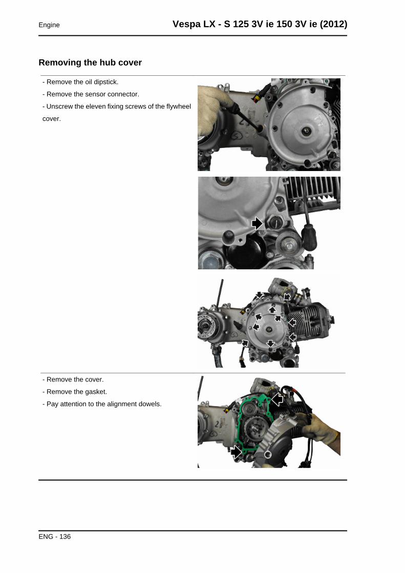
Removing the hub cover
- Remove the oil dipstick.
- Remove the sensor connector.
- Unscrew the eleven fixing screws of the flywheel
cover.
- Remove the cover.
- Remove the gasket.
- Pay attention to the alignment dowels.
Engine Vespa LX - S 125 3V ie 150 3V ie (2012)
ENG - 136
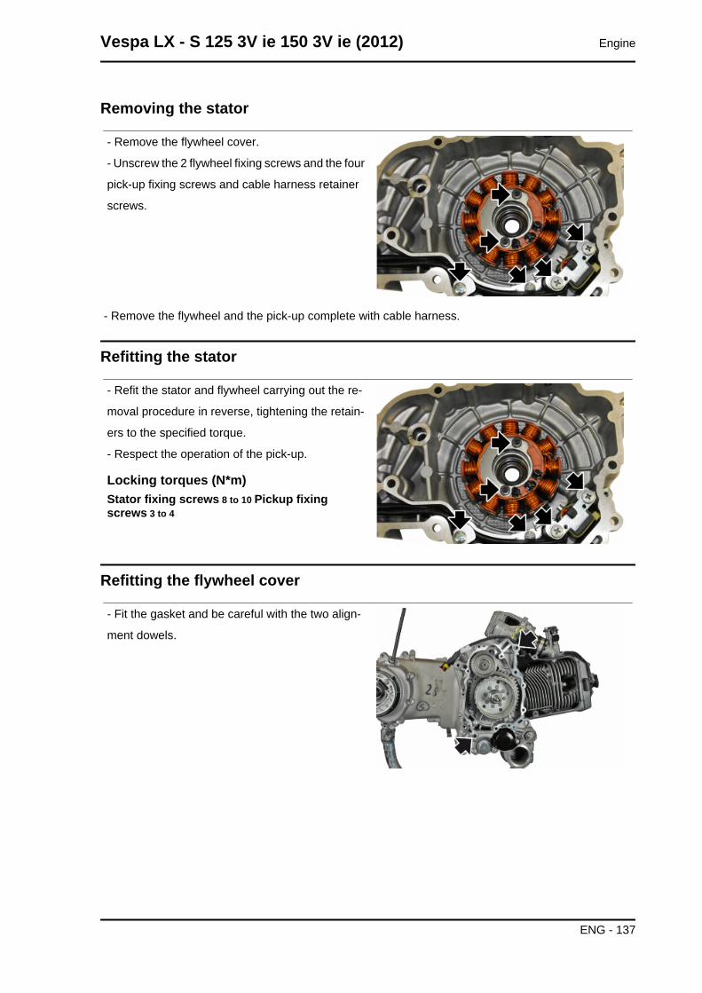
Removing the stator
- Remove the flywheel cover.
- Unscrew the 2 flywheel fixing screws and the four
pick-up fixing screws and cable harness retainer
screws.
- Remove the flywheel and the pick-up complete with cable harness.
Refitting the stator
- Refit the stator and flywheel carrying out the re-
moval procedure in reverse, tightening the retain-
ers to the specified torque.
- Respect the operation of the pick-up.
Locking torques (N*m)Stator fixing screws 8 to 10 Pickup fixingscrews 3 to 4
Refitting the flywheel cover
- Fit the gasket and be careful with the two align-
ment dowels.
Vespa LX - S 125 3V ie 150 3V ie (2012) Engine
ENG - 137
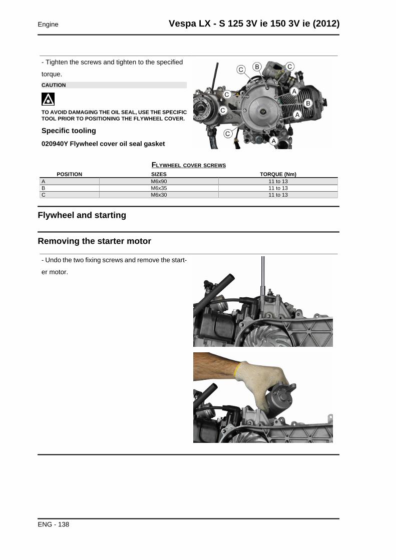
- Tighten the screws and tighten to the specified
torque.CAUTION
TO AVOID DAMAGING THE OIL SEAL, USE THE SPECIFICTOOL PRIOR TO POSITIONING THE FLYWHEEL COVER.
Specific tooling020940Y Flywheel cover oil seal gasket
FLYWHEEL COVER SCREWSPOSITION SIZES TORQUE (Nm)
A M6x90 11 to 13B M6x35 11 to 13C M6x30 11 to 13
Flywheel and starting
Removing the starter motor
- Undo the two fixing screws and remove the start-
er motor.
Engine Vespa LX - S 125 3V ie 150 3V ie (2012)
ENG - 138
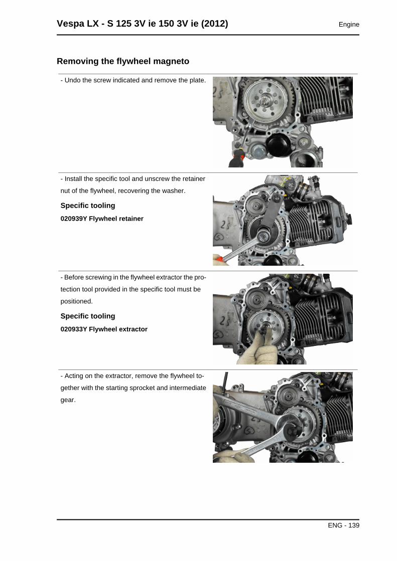
Removing the flywheel magneto
- Undo the screw indicated and remove the plate.
- Install the specific tool and unscrew the retainer
nut of the flywheel, recovering the washer.
Specific tooling020939Y Flywheel retainer
- Before screwing in the flywheel extractor the pro-
tection tool provided in the specific tool must be
positioned.
Specific tooling020933Y Flywheel extractor
- Acting on the extractor, remove the flywheel to-
gether with the starting sprocket and intermediate
gear.
Vespa LX - S 125 3V ie 150 3V ie (2012) Engine
ENG - 139
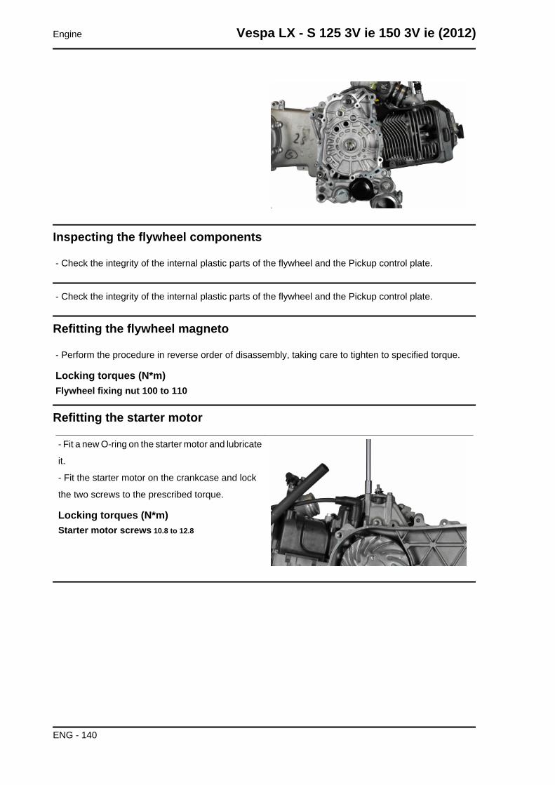
Inspecting the flywheel components
- Check the integrity of the internal plastic parts of the flywheel and the Pickup control plate.
- Check the integrity of the internal plastic parts of the flywheel and the Pickup control plate.
Refitting the flywheel magneto
- Perform the procedure in reverse order of disassembly, taking care to tighten to specified torque.
Locking torques (N*m)Flywheel fixing nut 100 to 110
Refitting the starter motor
- Fit a new O-ring on the starter motor and lubricate
it.
- Fit the starter motor on the crankcase and lock
the two screws to the prescribed torque.
Locking torques (N*m)Starter motor screws 10.8 to 12.8
Engine Vespa LX - S 125 3V ie 150 3V ie (2012)
ENG - 140
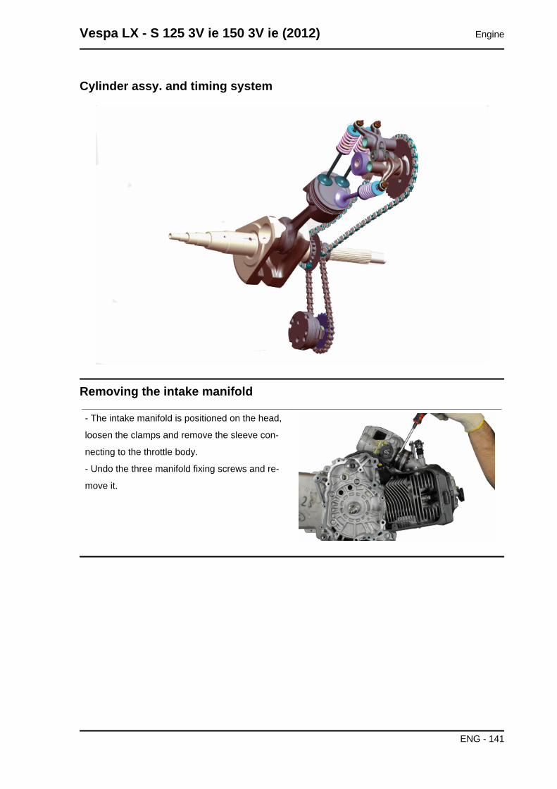
Cylinder assy. and timing system
Removing the intake manifold
- The intake manifold is positioned on the head,
loosen the clamps and remove the sleeve con-
necting to the throttle body.
- Undo the three manifold fixing screws and re-
move it.
Vespa LX - S 125 3V ie 150 3V ie (2012) Engine
ENG - 141
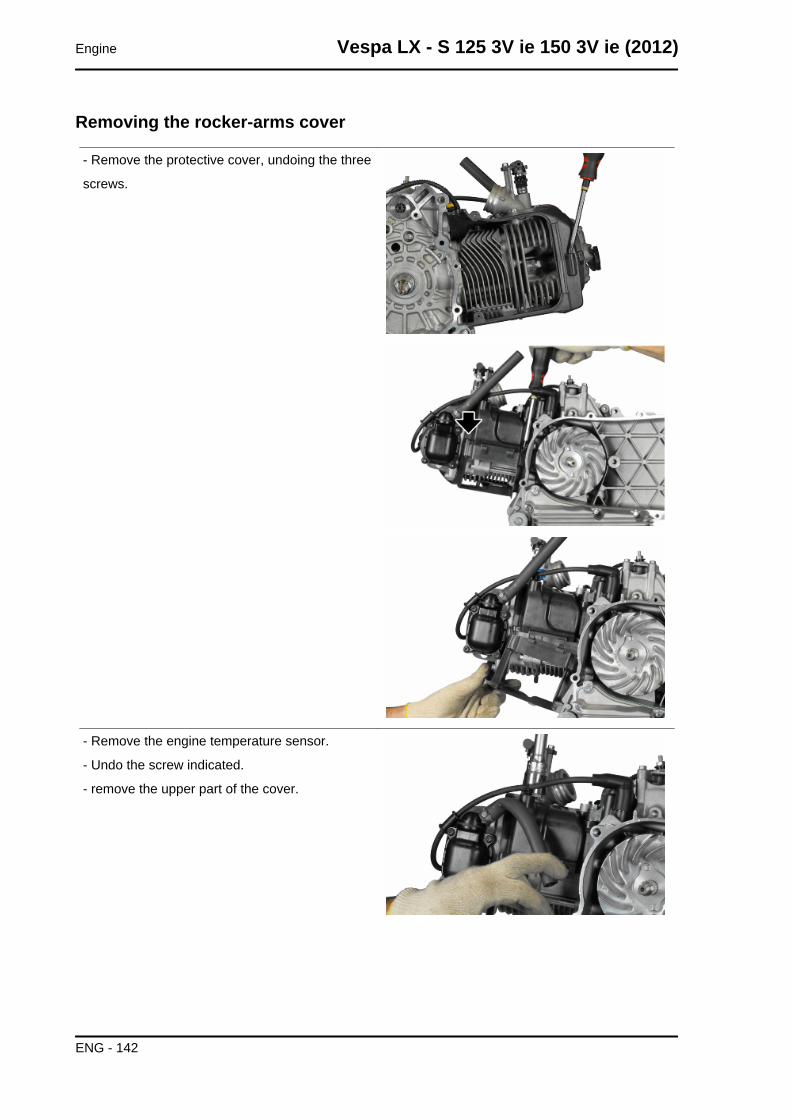
Removing the rocker-arms cover
- Remove the protective cover, undoing the three
screws.
- Remove the engine temperature sensor.
- Undo the screw indicated.
- remove the upper part of the cover.
Engine Vespa LX - S 125 3V ie 150 3V ie (2012)
ENG - 142
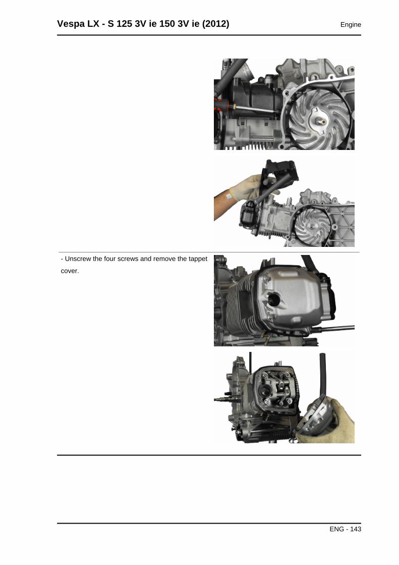
- Unscrew the four screws and remove the tappet
cover.
Vespa LX - S 125 3V ie 150 3V ie (2012) Engine
ENG - 143
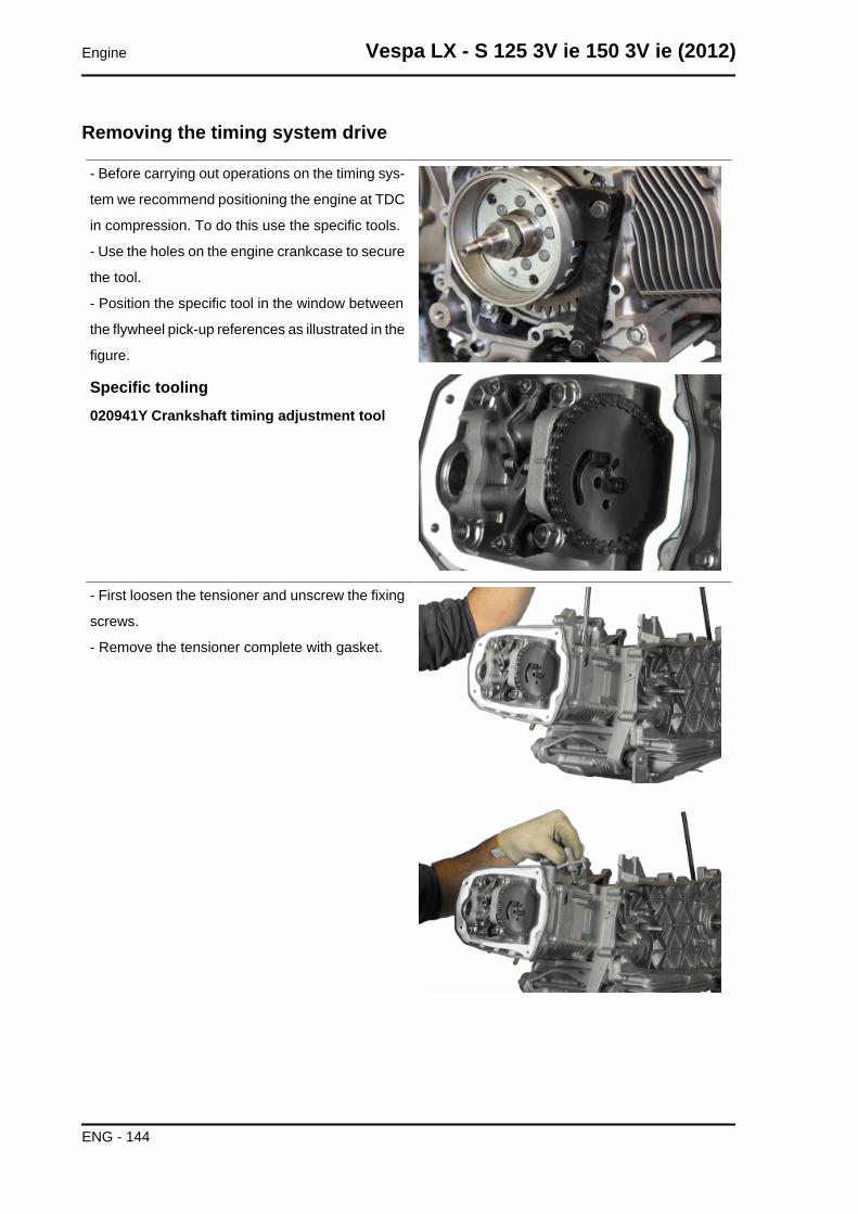
Removing the timing system drive
- Before carrying out operations on the timing sys-
tem we recommend positioning the engine at TDC
in compression. To do this use the specific tools.
- Use the holes on the engine crankcase to secure
the tool.
- Position the specific tool in the window between
the flywheel pick-up references as illustrated in the
figure.
Specific tooling020941Y Crankshaft timing adjustment tool
- First loosen the tensioner and unscrew the fixing
screws.
- Remove the tensioner complete with gasket.
Engine Vespa LX - S 125 3V ie 150 3V ie (2012)
ENG - 144
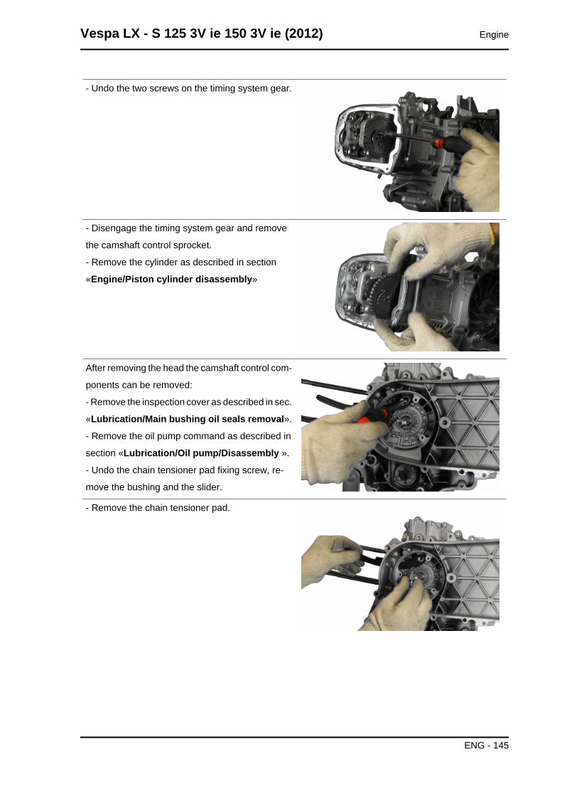
- Undo the two screws on the timing system gear.
- Disengage the timing system gear and remove
the camshaft control sprocket.
- Remove the cylinder as described in section
«Engine/Piston cylinder disassembly»
After removing the head the camshaft control com-
ponents can be removed:
- Remove the inspection cover as described in sec.
«Lubrication/Main bushing oil seals removal».
- Remove the oil pump command as described in
section «Lubrication/Oil pump/Disassembly ».
- Undo the chain tensioner pad fixing screw, re-
move the bushing and the slider.
- Remove the chain tensioner pad.
Vespa LX - S 125 3V ie 150 3V ie (2012) Engine
ENG - 145
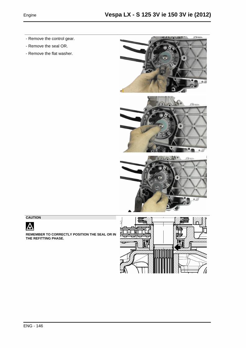
- Remove the control gear.
- Remove the seal OR.
- Remove the flat washer.
CAUTION
REMEMBER TO CORRECTLY POSITION THE SEAL OR INTHE REFITTING PHASE.
Engine Vespa LX - S 125 3V ie 150 3V ie (2012)
ENG - 146
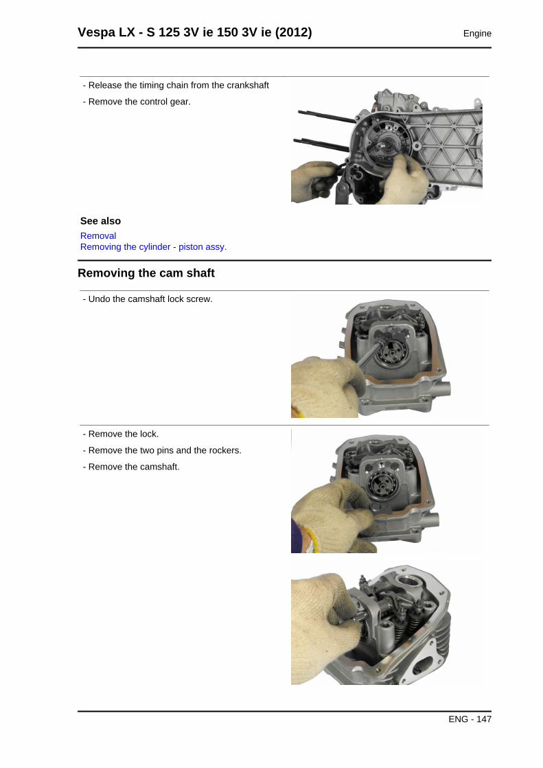
- Release the timing chain from the crankshaft
- Remove the control gear.
See alsoRemovalRemoving the cylinder - piston assy.
Removing the cam shaft
- Undo the camshaft lock screw.
- Remove the lock.
- Remove the two pins and the rockers.
- Remove the camshaft.
Vespa LX - S 125 3V ie 150 3V ie (2012) Engine
ENG - 147
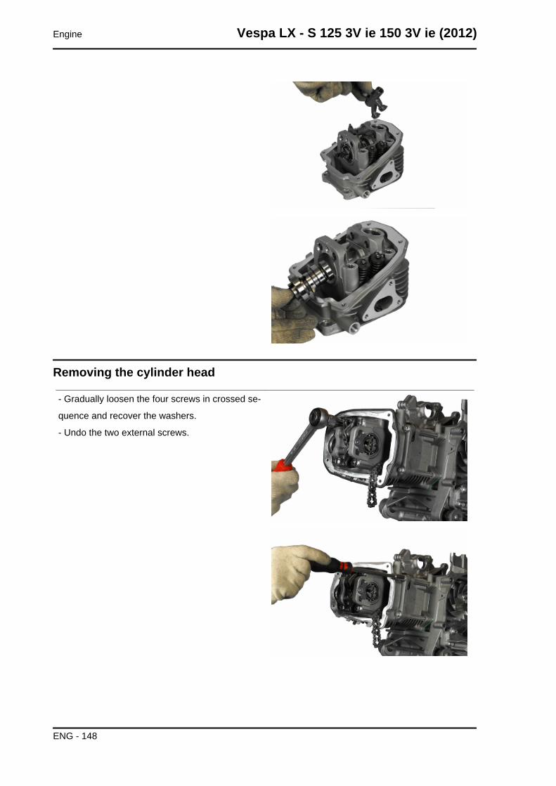
Removing the cylinder head
- Gradually loosen the four screws in crossed se-
quence and recover the washers.
- Undo the two external screws.
Engine Vespa LX - S 125 3V ie 150 3V ie (2012)
ENG - 148
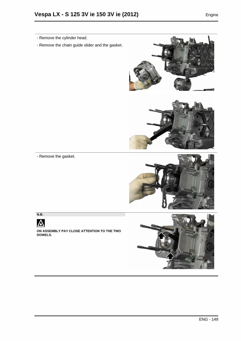
- Remove the cylinder head.
- Remove the chain guide slider and the gasket.
- Remove the gasket.
N.B.
ON ASSEMBLY PAY CLOSE ATTENTION TO THE TWODOWELS.
Vespa LX - S 125 3V ie 150 3V ie (2012) Engine
ENG - 149
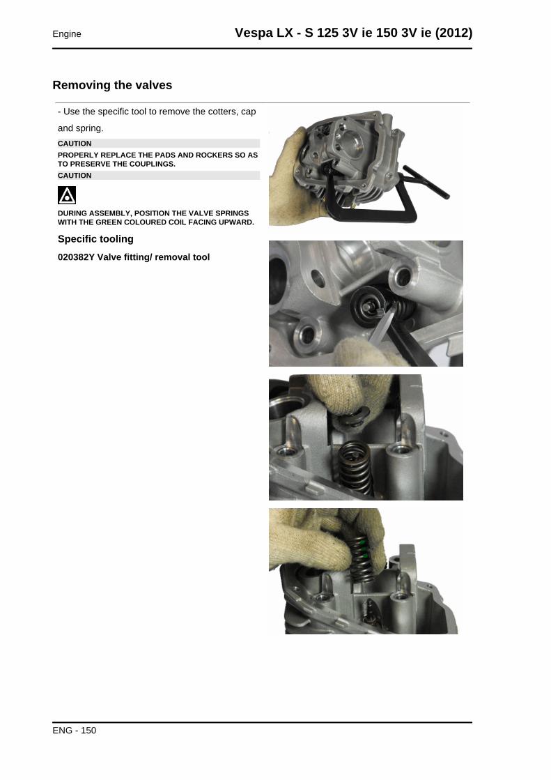
Removing the valves
- Use the specific tool to remove the cotters, cap
and spring.CAUTIONPROPERLY REPLACE THE PADS AND ROCKERS SO ASTO PRESERVE THE COUPLINGS.CAUTION
DURING ASSEMBLY, POSITION THE VALVE SPRINGSWITH THE GREEN COLOURED COIL FACING UPWARD.
Specific tooling020382Y Valve fitting/ removal tool
Engine Vespa LX - S 125 3V ie 150 3V ie (2012)
ENG - 150
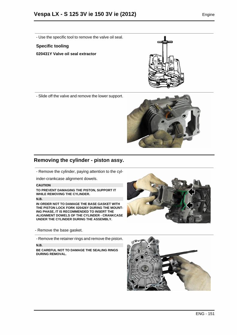
- Use the specific tool to remove the valve oil seal.
Specific tooling020431Y Valve oil seal extractor
- Slide off the valve and remove the lower support.
Removing the cylinder - piston assy.
- Remove the cylinder, paying attention to the cyl-
inder-crankcase alignment dowels.CAUTIONTO PREVENT DAMAGING THE PISTON, SUPPORT ITWHILE REMOVING THE CYLINDER.N.B.IN ORDER NOT TO DAMAGE THE BASE GASKET WITHTHE PISTON LOCK FORK 020426Y DURING THE MOUNT-ING PHASE, IT IS RECOMMENDED TO INSERT THEALIGNMENT DOWELS OF THE CYLINDER - CRANKCASEUNDER THE CYLINDER DURING THE ASSEMBLY.
- Remove the base gasket.
- Remove the retainer rings and remove the piston.N.B.BE CAREFUL NOT TO DAMAGE THE SEALING RINGSDURING REMOVAL.
Vespa LX - S 125 3V ie 150 3V ie (2012) Engine
ENG - 151
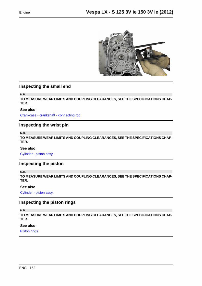
Inspecting the small endN.B.
TO MEASURE WEAR LIMITS AND COUPLING CLEARANCES, SEE THE SPECIFICATIONS CHAP-TER.
See alsoCrankcase - crankshaft - connecting rod
Inspecting the wrist pinN.B.
TO MEASURE WEAR LIMITS AND COUPLING CLEARANCES, SEE THE SPECIFICATIONS CHAP-TER.
See alsoCylinder - piston assy.
Inspecting the pistonN.B.
TO MEASURE WEAR LIMITS AND COUPLING CLEARANCES, SEE THE SPECIFICATIONS CHAP-TER.
See alsoCylinder - piston assy.
Inspecting the piston ringsN.B.
TO MEASURE WEAR LIMITS AND COUPLING CLEARANCES, SEE THE SPECIFICATIONS CHAP-TER.
See alsoPiston rings
Engine Vespa LX - S 125 3V ie 150 3V ie (2012)
ENG - 152
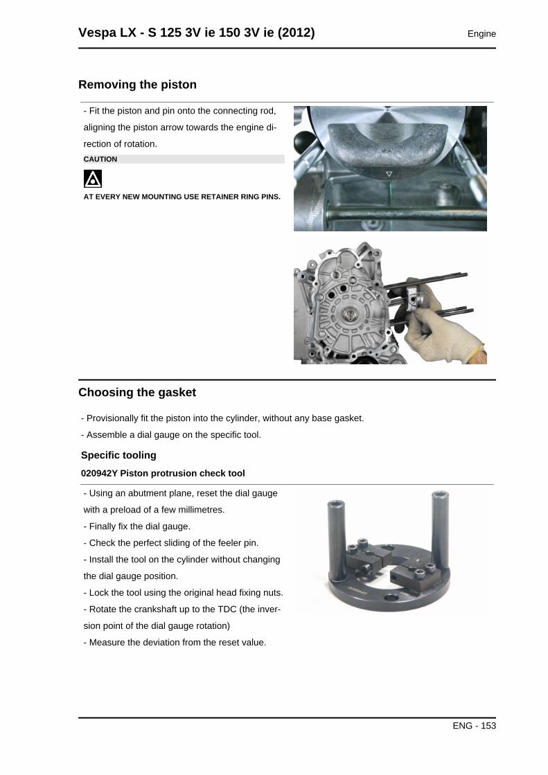
Removing the piston
- Fit the piston and pin onto the connecting rod,
aligning the piston arrow towards the engine di-
rection of rotation.CAUTION
AT EVERY NEW MOUNTING USE RETAINER RING PINS.
Choosing the gasket
- Provisionally fit the piston into the cylinder, without any base gasket.
- Assemble a dial gauge on the specific tool.
Specific tooling020942Y Piston protrusion check tool
- Using an abutment plane, reset the dial gauge
with a preload of a few millimetres.
- Finally fix the dial gauge.
- Check the perfect sliding of the feeler pin.
- Install the tool on the cylinder without changing
the dial gauge position.
- Lock the tool using the original head fixing nuts.
- Rotate the crankshaft up to the TDC (the inver-
sion point of the dial gauge rotation)
- Measure the deviation from the reset value.
Vespa LX - S 125 3V ie 150 3V ie (2012) Engine
ENG - 153
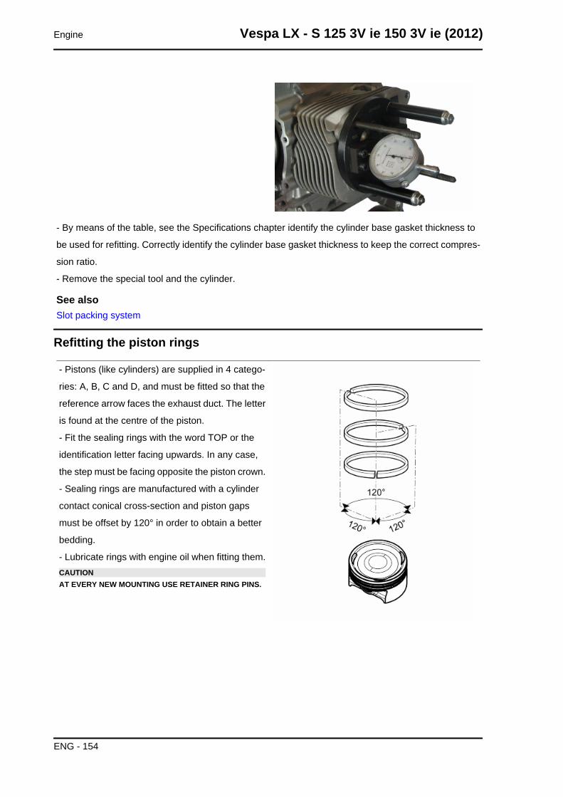
- By means of the table, see the Specifications chapter identify the cylinder base gasket thickness to
be used for refitting. Correctly identify the cylinder base gasket thickness to keep the correct compres-
sion ratio.
- Remove the special tool and the cylinder.
See alsoSlot packing system
Refitting the piston rings
- Pistons (like cylinders) are supplied in 4 catego-
ries: A, B, C and D, and must be fitted so that the
reference arrow faces the exhaust duct. The letter
is found at the centre of the piston.
- Fit the sealing rings with the word TOP or the
identification letter facing upwards. In any case,
the step must be facing opposite the piston crown.
- Sealing rings are manufactured with a cylinder
contact conical cross-section and piston gaps
must be offset by 120° in order to obtain a better
bedding.
- Lubricate rings with engine oil when fitting them.CAUTIONAT EVERY NEW MOUNTING USE RETAINER RING PINS.
Engine Vespa LX - S 125 3V ie 150 3V ie (2012)
ENG - 154
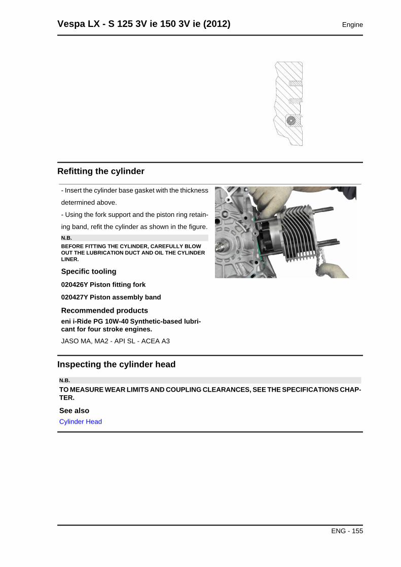
Refitting the cylinder
- Insert the cylinder base gasket with the thickness
determined above.
- Using the fork support and the piston ring retain-
ing band, refit the cylinder as shown in the figure.N.B.BEFORE FITTING THE CYLINDER, CAREFULLY BLOWOUT THE LUBRICATION DUCT AND OIL THE CYLINDERLINER.
Specific tooling020426Y Piston fitting fork
020427Y Piston assembly band
Recommended productseni i-Ride PG 10W-40 Synthetic-based lubri-cant for four stroke engines.JASO MA, MA2 - API SL - ACEA A3
Inspecting the cylinder headN.B.
TO MEASURE WEAR LIMITS AND COUPLING CLEARANCES, SEE THE SPECIFICATIONS CHAP-TER.
See alsoCylinder Head
Vespa LX - S 125 3V ie 150 3V ie (2012) Engine
ENG - 155
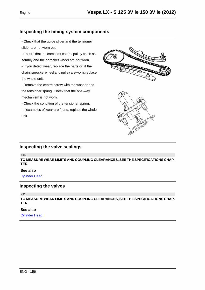
Inspecting the timing system components
- Check that the guide slider and the tensioner
slider are not worn out.
- Ensure that the camshaft control pulley chain as-
sembly and the sprocket wheel are not worn.
- If you detect wear, replace the parts or, if the
chain, sprocket wheel and pulley are worn, replace
the whole unit.
- Remove the centre screw with the washer and
the tensioner spring. Check that the one-way
mechanism is not worn.
- Check the condition of the tensioner spring.
- If examples of wear are found, replace the whole
unit.
Inspecting the valve sealingsN.B.
TO MEASURE WEAR LIMITS AND COUPLING CLEARANCES, SEE THE SPECIFICATIONS CHAP-TER.
See alsoCylinder Head
Inspecting the valvesN.B.
TO MEASURE WEAR LIMITS AND COUPLING CLEARANCES, SEE THE SPECIFICATIONS CHAP-TER.
See alsoCylinder Head
Engine Vespa LX - S 125 3V ie 150 3V ie (2012)
ENG - 156
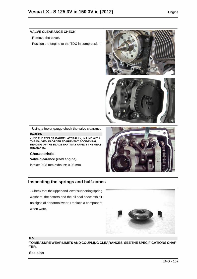
VALVE CLEARANCE CHECK
- Remove the cover.
- Position the engine to the TDC in compression
- Using a feeler gauge check the valve clearance.CAUTION- USE THE FEELER GAUGE LATERALLY, IN LINE WITHTHE VALVES, IN ORDER TO PREVENT ACCIDENTALBENDING OF THE BLADE THAT MAY AFFECT THE MEAS-UREMENTS.
CharacteristicValve clearance (cold engine)intake: 0.08 mm exhaust: 0.08 mm
Inspecting the springs and half-cones
- Check that the upper and lower supporting spring
washers, the cotters and the oil seal show exhibit
no signs of abnormal wear. Replace a component
when worn.
N.B.TO MEASURE WEAR LIMITS AND COUPLING CLEARANCES, SEE THE SPECIFICATIONS CHAP-TER.
See also
Vespa LX - S 125 3V ie 150 3V ie (2012) Engine
ENG - 157
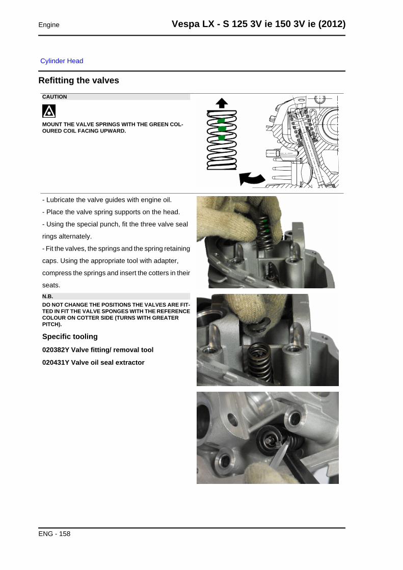
Cylinder Head
Refitting the valvesCAUTION
MOUNT THE VALVE SPRINGS WITH THE GREEN COL-OURED COIL FACING UPWARD.
- Lubricate the valve guides with engine oil.
- Place the valve spring supports on the head.
- Using the special punch, fit the three valve seal
rings alternately.
- Fit the valves, the springs and the spring retaining
caps. Using the appropriate tool with adapter,
compress the springs and insert the cotters in their
seats.N.B.DO NOT CHANGE THE POSITIONS THE VALVES ARE FIT-TED IN FIT THE VALVE SPONGES WITH THE REFERENCECOLOUR ON COTTER SIDE (TURNS WITH GREATERPITCH).
Specific tooling020382Y Valve fitting/ removal tool
020431Y Valve oil seal extractor
Engine Vespa LX - S 125 3V ie 150 3V ie (2012)
ENG - 158
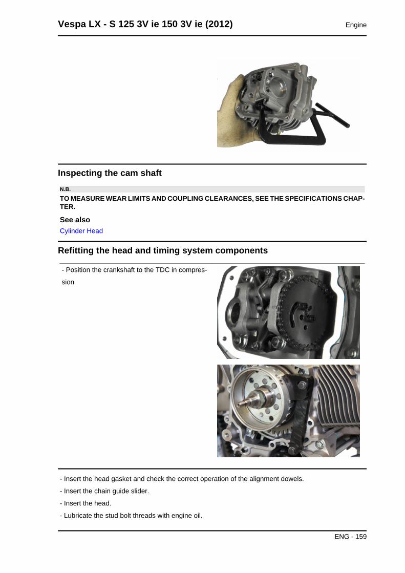
Inspecting the cam shaftN.B.
TO MEASURE WEAR LIMITS AND COUPLING CLEARANCES, SEE THE SPECIFICATIONS CHAP-TER.
See alsoCylinder Head
Refitting the head and timing system components
- Position the crankshaft to the TDC in compres-
sion
- Insert the head gasket and check the correct operation of the alignment dowels.
- Insert the chain guide slider.
- Insert the head.
- Lubricate the stud bolt threads with engine oil.
Vespa LX - S 125 3V ie 150 3V ie (2012) Engine
ENG - 159
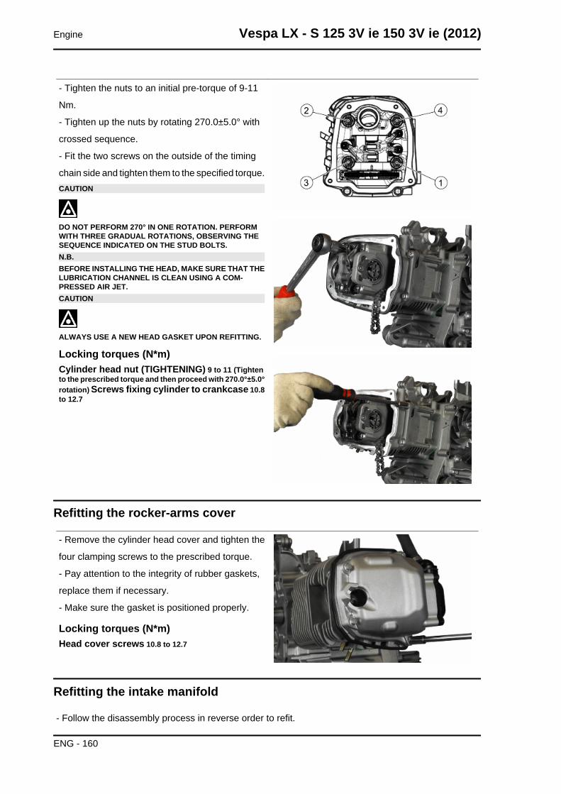
- Tighten the nuts to an initial pre-torque of 9-11
Nm.
- Tighten up the nuts by rotating 270.0±5.0° with
crossed sequence.
- Fit the two screws on the outside of the timing
chain side and tighten them to the specified torque.CAUTION
DO NOT PERFORM 270° IN ONE ROTATION. PERFORMWITH THREE GRADUAL ROTATIONS, OBSERVING THESEQUENCE INDICATED ON THE STUD BOLTS.N.B.BEFORE INSTALLING THE HEAD, MAKE SURE THAT THELUBRICATION CHANNEL IS CLEAN USING A COM-PRESSED AIR JET.CAUTION
ALWAYS USE A NEW HEAD GASKET UPON REFITTING.
Locking torques (N*m)Cylinder head nut (TIGHTENING) 9 to 11 (Tightento the prescribed torque and then proceed with 270.0°±5.0°rotation) Screws fixing cylinder to crankcase 10.8to 12.7
Refitting the rocker-arms cover
- Remove the cylinder head cover and tighten the
four clamping screws to the prescribed torque.
- Pay attention to the integrity of rubber gaskets,
replace them if necessary.
- Make sure the gasket is positioned properly.
Locking torques (N*m)Head cover screws 10.8 to 12.7
Refitting the intake manifold
- Follow the disassembly process in reverse order to refit.
Engine Vespa LX - S 125 3V ie 150 3V ie (2012)
ENG - 160
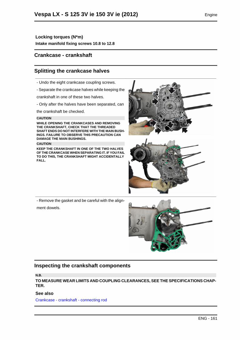
Locking torques (N*m)Intake manifold fixing screws 10.8 to 12.8
Crankcase - crankshaft
Splitting the crankcase halves
- Undo the eight crankcase coupling screws.
- Separate the crankcase halves while keeping the
crankshaft in one of these two halves.
- Only after the halves have been separated, can
the crankshaft be checked.CAUTIONWHILE OPENING THE CRANKCASES AND REMOVINGTHE CRANKSHAFT, CHECK THAT THE THREADEDSHAFT ENDS DO NOT INTERFERE WITH THE MAIN BUSH-INGS. FAILURE TO OBSERVE THIS PRECAUTION CANDAMAGE THE MAIN BUSHINGS.CAUTIONKEEP THE CRANKSHAFT IN ONE OF THE TWO HALVESOF THE CRANKCASE WHEN SEPARATING IT. IF YOU FAILTO DO THIS, THE CRANKSHAFT MIGHT ACCIDENTALLYFALL.
- Remove the gasket and be careful with the align-
ment dowels.
Inspecting the crankshaft componentsN.B.
TO MEASURE WEAR LIMITS AND COUPLING CLEARANCES, SEE THE SPECIFICATIONS CHAP-TER.
See alsoCrankcase - crankshaft - connecting rod
Vespa LX - S 125 3V ie 150 3V ie (2012) Engine
ENG - 161
Inspecting the crankshaft alignmentN.B.
TO MEASURE WEAR LIMITS AND COUPLING CLEARANCES, SEE THE SPECIFICATIONS CHAP-TER.
See alsoCrankcase - crankshaft - connecting rod
Inspecting the crankcase halves
- Before proceeding to check the crankcase halves, thoroughly clean all surfaces and oil ducts.
- On the transmission-side crankcase half, take particular care when handling the oil pump compartment
and the oil ducts, the by-pass duct, the main bushings and the cooling jet on the transmission side.
- Take particular care, also, that there are no signs wear in the oil by-pass valve housing (see Chapter
Lubrication), as this could prevent a good seal in the piston, which regulates the oil pressure.
- On the flywheel side crankcase half, take particular care cleaning the oil ducts for the main bushings,
the oil duct for the jet that lubricates the cylinder head and the oil drainage duct at the flywheel side oil
seal.
- Inspect the coupling surfaces on the crankcase halves for scratches or deformation, taking particular
care with the cylinder/crankcase surfaces and the crankcase halves surfaces.
- Defects in the crankcase coupling gasket between the crankcase halves or the mating surfaces shown
in the diagram, could cause a drop in the oil pressure lubricating the main bushings and connecting
rod.
- Check the main bearing seats that limit axial clearance in the crankshaft show no signs of wear. The
dimension between these seats is measured by way of the procedure described previously for meas-
uring the crankshaft axial clearance and dimensions.N.B.
THE JET IS FED THROUGH THE MAIN BUSHINGS. PROPER OPERATION OF THIS COMPONENTIMPROVES PISTON CROWN COOLING. CLOGGING HAS EFFECTS THAT ARE DIFFICULT TODETECT (PISTON TEMPERATURE INCREASE). FAILURE OR LEAKS CAN CAUSE A CONSID-ERABLE DROP IN THE LUBRICATION PRESSURE FOR MAIN BUSHINGS AND CONNECTINGROD.N.B.
THE HEAD LUBRICATION CHANNEL IS PROVIDED WITH A SHUTTER JET; THIS GIVES A "LOWPRESSURE" HEAD LUBRICATION; THIS CHOICE WAS MADE TO REDUCE THE OIL TEMPER-ATURE IN THE SUMP. THE JET CLOGGING IMPAIRS THE HEAD LUBRICATION AND THE TIMINGMECHANISMS. A JET FAILURE CAUSES A DECREASE OF THE MAIN BUSHING AND CON-NECTING ROD LUBRICATION PRESSURE.
Engine Vespa LX - S 125 3V ie 150 3V ie (2012)
ENG - 162
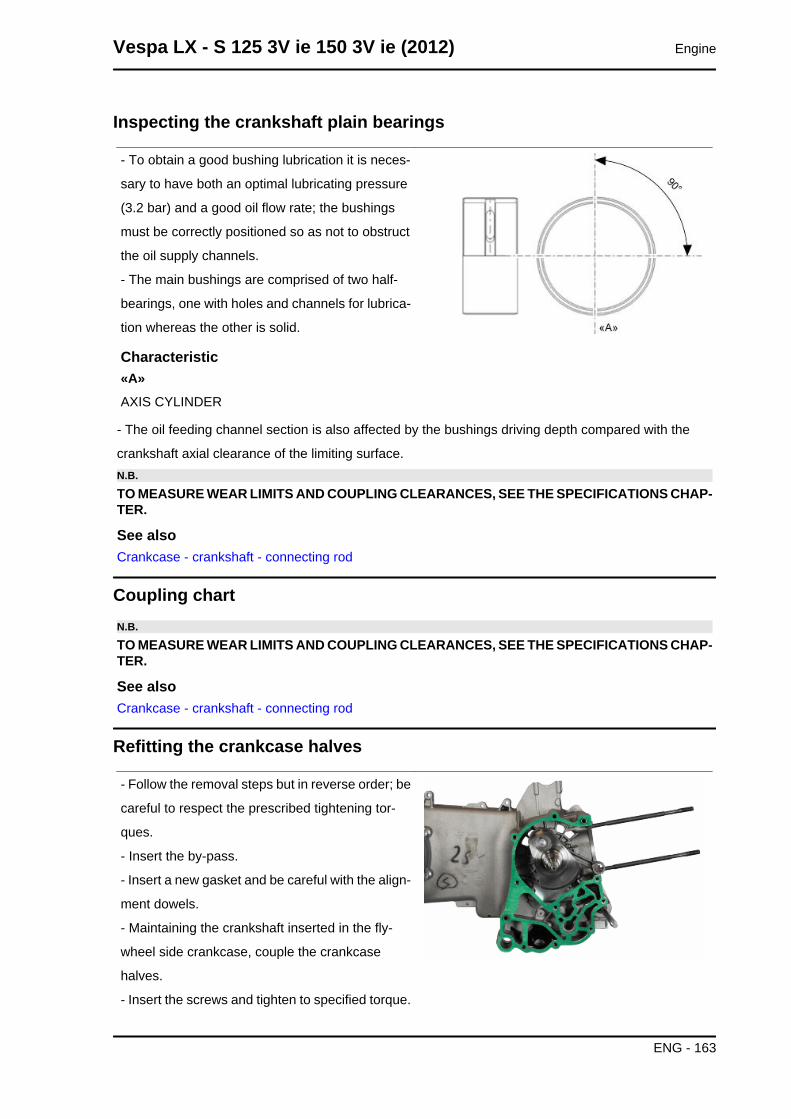
Inspecting the crankshaft plain bearings
- To obtain a good bushing lubrication it is neces-
sary to have both an optimal lubricating pressure
(3.2 bar) and a good oil flow rate; the bushings
must be correctly positioned so as not to obstruct
the oil supply channels.
- The main bushings are comprised of two half-
bearings, one with holes and channels for lubrica-
tion whereas the other is solid.
Characteristic«A»AXIS CYLINDER
- The oil feeding channel section is also affected by the bushings driving depth compared with the
crankshaft axial clearance of the limiting surface.N.B.
TO MEASURE WEAR LIMITS AND COUPLING CLEARANCES, SEE THE SPECIFICATIONS CHAP-TER.
See alsoCrankcase - crankshaft - connecting rod
Coupling chartN.B.
TO MEASURE WEAR LIMITS AND COUPLING CLEARANCES, SEE THE SPECIFICATIONS CHAP-TER.
See alsoCrankcase - crankshaft - connecting rod
Refitting the crankcase halves
- Follow the removal steps but in reverse order; be
careful to respect the prescribed tightening tor-
ques.
- Insert the by-pass.
- Insert a new gasket and be careful with the align-
ment dowels.
- Maintaining the crankshaft inserted in the fly-
wheel side crankcase, couple the crankcase
halves.
- Insert the screws and tighten to specified torque.
Vespa LX - S 125 3V ie 150 3V ie (2012) Engine
ENG - 163
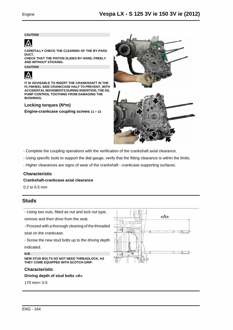
CAUTION
CAREFULLY CHECK THE CLEANING OF THE BY-PASSDUCT.CHECK THAT THE PISTON SLIDES BY HAND, FREELYAND WITHOUT STICKING.CAUTION
IT IS ADVISABLE TO INSERT THE CRANKSHAFT IN THEFLYWHEEL SIDE CRANKCASE HALF TO PREVENT, WITHACCIDENTAL MOVEMENTS DURING INSERTION, THE OILPUMP CONTROL TOOTHING FROM DAMAGING THEBUSHINGS.
Locking torques (N*m)Engine-crankcase coupling screws 11 ÷ 13
- Complete the coupling operations with the verification of the crankshaft axial clearance.
- Using specific tools to support the dial gauge, verify that the fitting clearance is within the limits.
- Higher clearances are signs of wear of the crankshaft - crankcase supporting surfaces.
CharacteristicCrankshaft-crankcase axial clearance
0.2 to 0.5 mm
Studs
- Using two nuts, fitted as nut and lock nut type,
remove and then drive from the seat.
- Proceed with a thorough cleaning of the threaded
seat on the crankcase.
- Screw the new stud bolts up to the driving depth
indicated.N.B.NEW STUD BOLTS DO NOT NEED THREADLOCK, ASTHEY COME EQUIPPED WITH SCOTCH-GRIP.
CharacteristicDriving depth of stud bolts «A»170 mm+ 0.5
Engine Vespa LX - S 125 3V ie 150 3V ie (2012)
ENG - 164
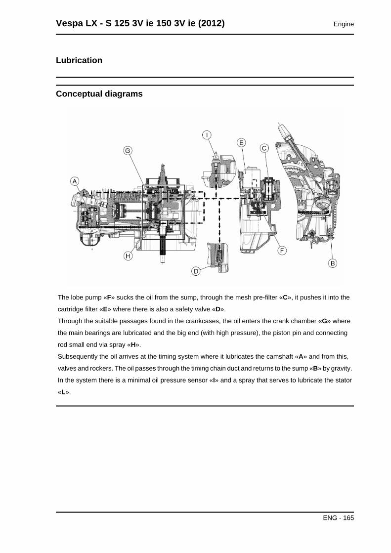
Lubrication
Conceptual diagrams
The lobe pump «F» sucks the oil from the sump, through the mesh pre-filter «C», it pushes it into the
cartridge filter «E» where there is also a safety valve «D».
Through the suitable passages found in the crankcases, the oil enters the crank chamber «G» where
the main bearings are lubricated and the big end (with high pressure), the piston pin and connecting
rod small end via spray «H».
Subsequently the oil arrives at the timing system where it lubricates the camshaft «A» and from this,
valves and rockers. The oil passes through the timing chain duct and returns to the sump «B» by gravity.
In the system there is a minimal oil pressure sensor «I» and a spray that serves to lubricate the stator
«L».
Vespa LX - S 125 3V ie 150 3V ie (2012) Engine
ENG - 165
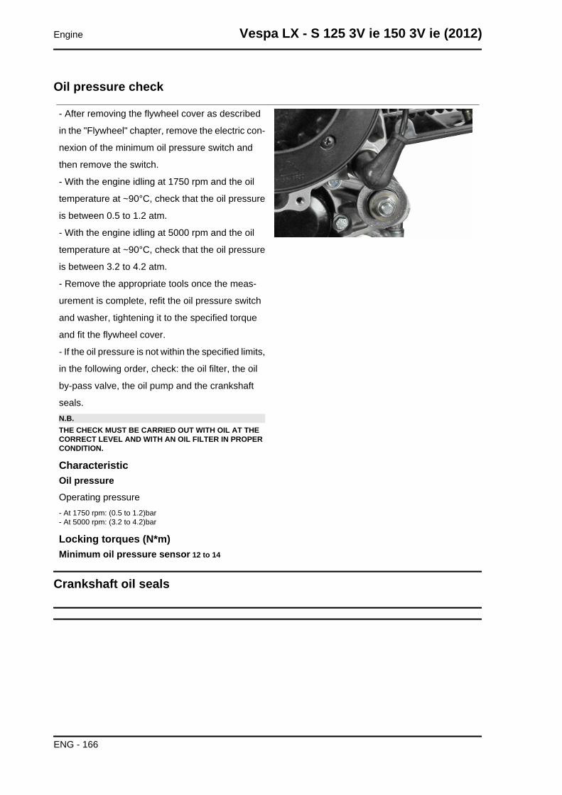
Oil pressure check
- After removing the flywheel cover as described
in the "Flywheel" chapter, remove the electric con-
nexion of the minimum oil pressure switch and
then remove the switch.
- With the engine idling at 1750 rpm and the oil
temperature at ~90°C, check that the oil pressure
is between 0.5 to 1.2 atm.
- With the engine idling at 5000 rpm and the oil
temperature at ~90°C, check that the oil pressure
is between 3.2 to 4.2 atm.
- Remove the appropriate tools once the meas-
urement is complete, refit the oil pressure switch
and washer, tightening it to the specified torque
and fit the flywheel cover.
- If the oil pressure is not within the specified limits,
in the following order, check: the oil filter, the oil
by-pass valve, the oil pump and the crankshaft
seals.N.B.THE CHECK MUST BE CARRIED OUT WITH OIL AT THECORRECT LEVEL AND WITH AN OIL FILTER IN PROPERCONDITION.
CharacteristicOil pressureOperating pressure- At 1750 rpm: (0.5 to 1.2)bar- At 5000 rpm: (3.2 to 4.2)bar
Locking torques (N*m)Minimum oil pressure sensor 12 to 14
Crankshaft oil seals
Engine Vespa LX - S 125 3V ie 150 3V ie (2012)
ENG - 166
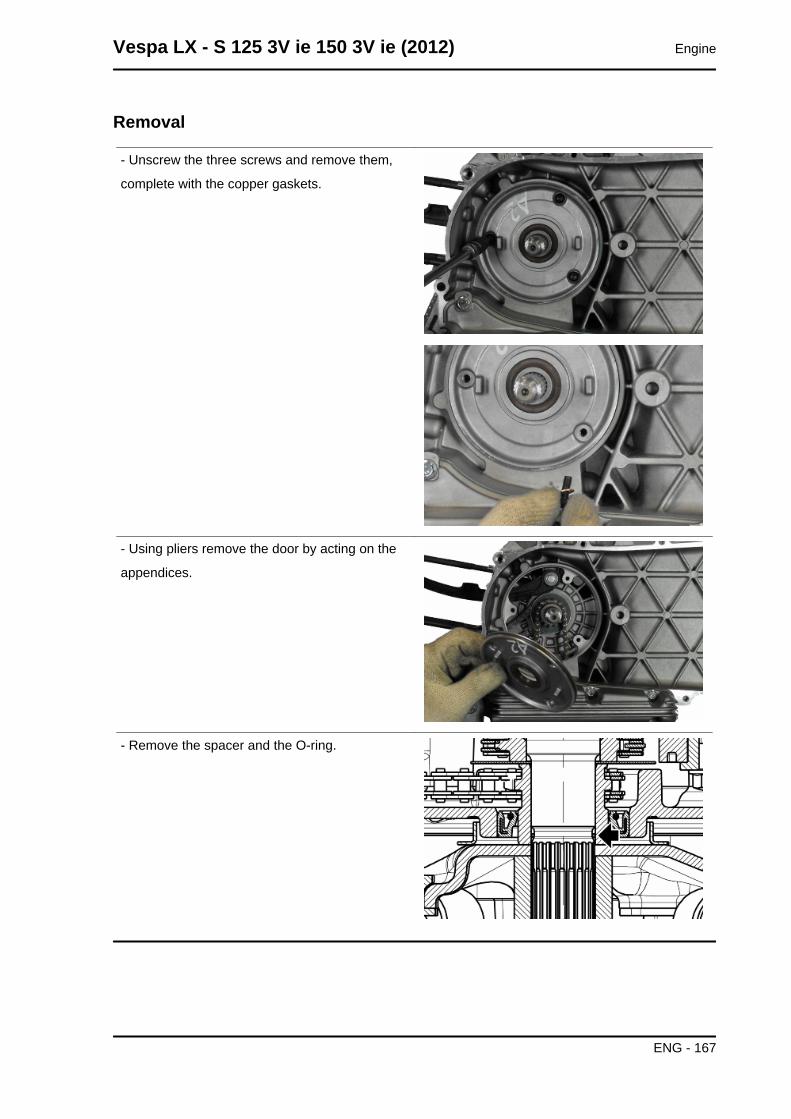
Removal
- Unscrew the three screws and remove them,
complete with the copper gaskets.
- Using pliers remove the door by acting on the
appendices.
- Remove the spacer and the O-ring.
Vespa LX - S 125 3V ie 150 3V ie (2012) Engine
ENG - 167
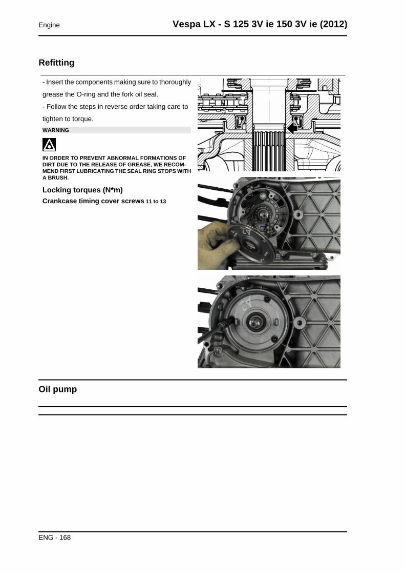
Refitting
- Insert the components making sure to thoroughly
grease the O-ring and the fork oil seal.
- Follow the steps in reverse order taking care to
tighten to torque.WARNING
IN ORDER TO PREVENT ABNORMAL FORMATIONS OFDIRT DUE TO THE RELEASE OF GREASE, WE RECOM-MEND FIRST LUBRICATING THE SEAL RING STOPS WITHA BRUSH.
Locking torques (N*m)Crankcase timing cover screws 11 to 13
Oil pump
Engine Vespa LX - S 125 3V ie 150 3V ie (2012)
ENG - 168
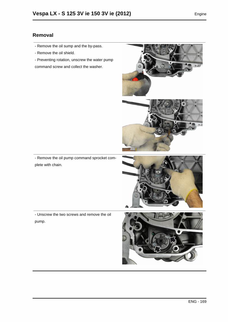
Removal
- Remove the oil sump and the by-pass.
- Remove the oil shield.
- Preventing rotation, unscrew the water pump
command screw and collect the washer.
- Remove the oil pump command sprocket com-
plete with chain.
- Unscrew the two screws and remove the oil
pump.
Vespa LX - S 125 3V ie 150 3V ie (2012) Engine
ENG - 169
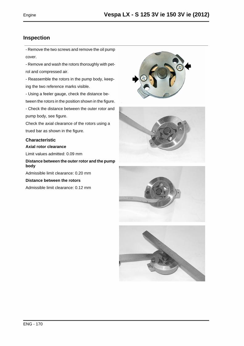
Inspection
- Remove the two screws and remove the oil pump
cover.
- Remove and wash the rotors thoroughly with pet-
rol and compressed air.
- Reassemble the rotors in the pump body, keep-
ing the two reference marks visible.
- Using a feeler gauge, check the distance be-
tween the rotors in the position shown in the figure.
- Check the distance between the outer rotor and
pump body, see figure.
Check the axial clearance of the rotors using a
trued bar as shown in the figure.
CharacteristicAxial rotor clearanceLimit values admitted: 0.09 mm
Distance between the outer rotor and the pumpbodyAdmissible limit clearance: 0.20 mm
Distance between the rotorsAdmissible limit clearance: 0.12 mm
Engine Vespa LX - S 125 3V ie 150 3V ie (2012)
ENG - 170
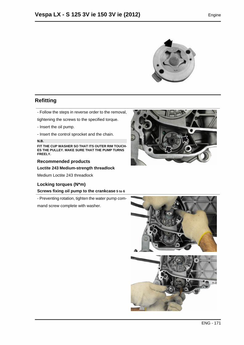
Refitting
- Follow the steps in reverse order to the removal,
tightening the screws to the specified torque.
- Insert the oil pump.
- Insert the control sprocket and the chain.N.B.FIT THE CUP WASHER SO THAT ITS OUTER RIM TOUCH-ES THE PULLEY. MAKE SURE THAT THE PUMP TURNSFREELY.
Recommended productsLoctite 243 Medium-strength threadlockMedium Loctite 243 threadlock
Locking torques (N*m)Screws fixing oil pump to the crankcase 5 to 6
- Preventing rotation, tighten the water pump com-
mand screw complete with washer.
Vespa LX - S 125 3V ie 150 3V ie (2012) Engine
ENG - 171
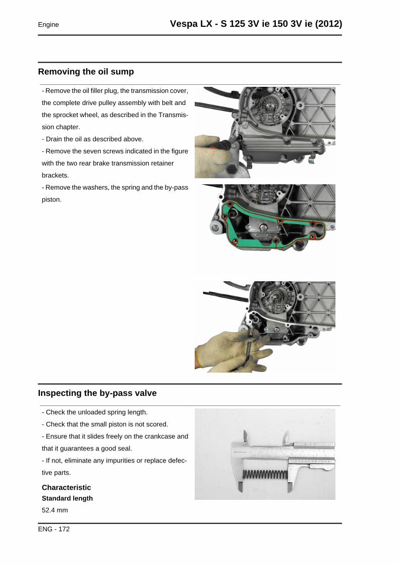
Removing the oil sump
- Remove the oil filler plug, the transmission cover,
the complete drive pulley assembly with belt and
the sprocket wheel, as described in the Transmis-
sion chapter.
- Drain the oil as described above.
- Remove the seven screws indicated in the figure
with the two rear brake transmission retainer
brackets.
- Remove the washers, the spring and the by-pass
piston.
Inspecting the by-pass valve
- Check the unloaded spring length.
- Check that the small piston is not scored.
- Ensure that it slides freely on the crankcase and
that it guarantees a good seal.
- If not, eliminate any impurities or replace defec-
tive parts.
CharacteristicStandard length52.4 mm
Engine Vespa LX - S 125 3V ie 150 3V ie (2012)
ENG - 172
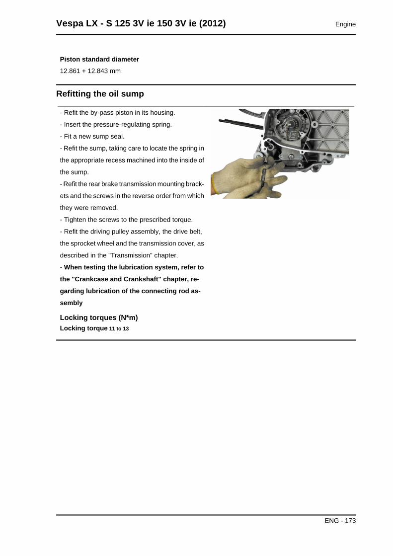
Piston standard diameter12.861 + 12.843 mm
Refitting the oil sump
- Refit the by-pass piston in its housing.
- Insert the pressure-regulating spring.
- Fit a new sump seal.
- Refit the sump, taking care to locate the spring in
the appropriate recess machined into the inside of
the sump.
- Refit the rear brake transmission mounting brack-
ets and the screws in the reverse order from which
they were removed.
- Tighten the screws to the prescribed torque.
- Refit the driving pulley assembly, the drive belt,
the sprocket wheel and the transmission cover, as
described in the "Transmission" chapter.
- When testing the lubrication system, refer to
the "Crankcase and Crankshaft" chapter, re-
garding lubrication of the connecting rod as-
sembly
Locking torques (N*m)Locking torque 11 to 13
Vespa LX - S 125 3V ie 150 3V ie (2012) Engine
ENG - 173
INDEX OF TOPICS
INJECTION INJEC

COMPONENT LAYOUTSpecification Desc./Quantity
1 Instrument panel2 Throttle body and electronic injection control unit (MIU)3 Diagnostics socket connector4 Fuel pump5 Engine temperature sensor6 Fuel injector7 HV coil8 Engine speed sensor9 Lambda probe10 Injection load relay11 Battery
MIU injection system
This vehicle is fitted with an integrated injection and ignition system.
Injection is indirect in the manifold through an electro-injector.
The injection and ignition are timed on the four-stroke cycle by means of a tone wheel keyed on to the
crankshaft (24-2 teeth) and pick-up sensor.
Combustion and ignition are managed on the basis of engine revs and throttle valve opening. Further
corrections are made according to the following parameters:
- Engine temperature
- Intake air temperature
- Lambda probe
The system implements cold engine idle fuel/air mixture correction with a stepper motor on a by-pass
circuit of the throttle valve. The control unit manages the Stepper motor and the injector opening time,
thereby ensuring the idle steadiness and the proper combustion.
In all conditions of use, mixture preparation is managed by modifying the injector opening time.
Vespa LX - S 125 3V ie 150 3V ie (2012) Injection
INJEC - 175

The fuel system pressure is kept constant in relation to ambient pressure.
The fuel system circuit consists of:
- Fuel pump
- Fuel filter
- Injector
- Pressure regulator
The pump, the filter and the regulator are placed inside the fuel tank on a single support.
The injector is connected by a pipe with fast-release fittings. The pressure regulator is located at the
beginning of the circuit.
The fuel pump is controlled by the MIU; this ensures safety of the vehicle.
The ignition circuit consists of:
- HV coil
- HV cable.
- Shielded cap
- MIU control unit
- Spark plug
The MIU control unit manages ignition with the best advance ensuring four-stroke timing (ignition only
in the compression phase) at the same time.
The MIU injection-ignition system controls engine functions by means of a pre-set program.
Should any input signals fail, an acceptable working order of the engine is ensured to allow the user to
reach a service station.
Of course, this cannot happen when the rpm-timing signal is missing, or when the failure involves the
control circuits:
- Fuel pump
- HV coil
- Injector
The control unit is provided with a self-diagnosis
system connected to an indicator light in the in-
strument panel.
Injection Vespa LX - S 125 3V ie 150 3V ie (2012)
INJEC - 176
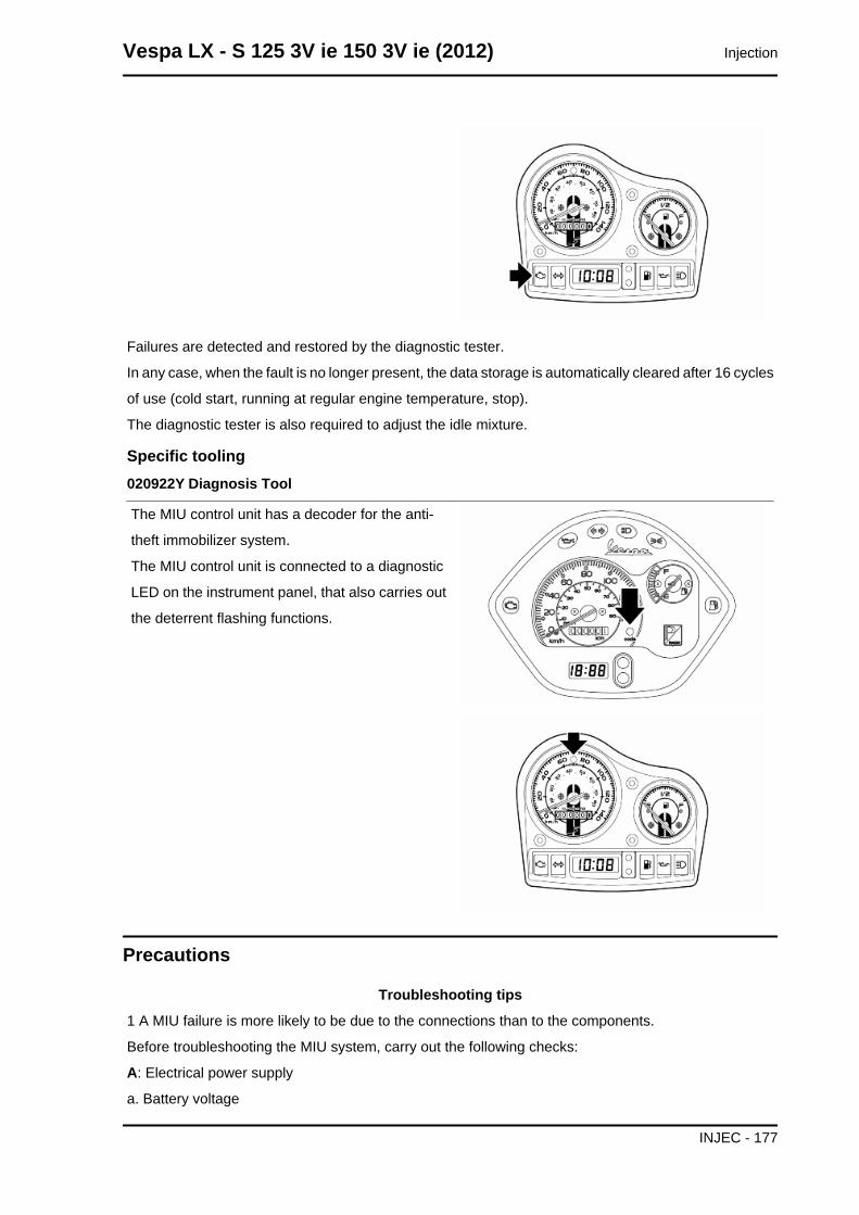
Failures are detected and restored by the diagnostic tester.
In any case, when the fault is no longer present, the data storage is automatically cleared after 16 cycles
of use (cold start, running at regular engine temperature, stop).
The diagnostic tester is also required to adjust the idle mixture.
Specific tooling020922Y Diagnosis Tool
The MIU control unit has a decoder for the anti-
theft immobilizer system.
The MIU control unit is connected to a diagnostic
LED on the instrument panel, that also carries out
the deterrent flashing functions.
Precautions
Troubleshooting tips
1 A MIU failure is more likely to be due to the connections than to the components.
Before troubleshooting the MIU system, carry out the following checks:
A: Electrical power supply
a. Battery voltage
Vespa LX - S 125 3V ie 150 3V ie (2012) Injection
INJEC - 177
b.Burnt fuse
c.Remote control switches
d.Connectors
B: Chassis ground
C: Fuel system
a. Faulty fuel pump
b.Dirty fuel filter
D: Ignition system
a. Faulty spark plug
b.Faulty coil
c.Faulty screened cap
E: Intake circuit
a. Air filter dirty
b.Dirty by-pass circuit
c.Faulty stepper motor
F: Other
a. Wrong distribution timing
b.Incorrect idle speed carburetion
c.Incorrect reset of the throttle valve position sensor
2 MIU system faults may be caused by loose connectors. Make sure that all connections have been
correctly made.
Check the connectors taking into consideration the following point:
A check that the terminals are not bent.
B check that the connectors have been properly connected.
C - Check whether the malfunction can be fixed by shaking the connector slightly.
3 Check the entire system before replacing the MIUIf the fault is fixed by replacing the MIU, install the
original control unit again and check if the fault occurs again.
4 Use a multimeter with an internal resistance of more than 10K Ohm /V when troubleshooting. Instru-
ments that are not suitable might damage the MIU central control unit. Use instruments with definitions
over 0.1V and 0.5 W , the precision must be greater than 2%.
1. Before fixing any part of the injection system, check to see if there are any registered faults. Do not
disconnect the battery before checking for faults.
2. The fuel system is pressurised at 250 kPa (2.5 BAR). Before disconnecting the fast-release fitting of
the fuel supply pipe, check that there are no naked flames. Do not smoke. Act with caution to avoid
spraying fuel to your eyes.
3. When fixing electric components, operate with the battery connected only when actually required.
4. When functional checks are performed, check that the battery voltage is over 12V.
Injection Vespa LX - S 125 3V ie 150 3V ie (2012)
INJEC - 178
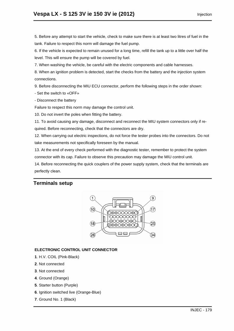
5. Before any attempt to start the vehicle, check to make sure there is at least two litres of fuel in the
tank. Failure to respect this norm will damage the fuel pump.
6. If the vehicle is expected to remain unused for a long time, refill the tank up to a little over half the
level. This will ensure the pump will be covered by fuel.
7. When washing the vehicle, be careful with the electric components and cable harnesses.
8. When an ignition problem is detected, start the checks from the battery and the injection system
connections.
9. Before disconnecting the MIU ECU connector, perform the following steps in the order shown:
- Set the switch to «OFF»
- Disconnect the battery
Failure to respect this norm may damage the control unit.
10. Do not invert the poles when fitting the battery.
11. To avoid causing any damage, disconnect and reconnect the MIU system connectors only if re-
quired. Before reconnecting, check that the connectors are dry.
12. When carrying out electric inspections, do not force the tester probes into the connectors. Do not
take measurements not specifically foreseen by the manual.
13. At the end of every check performed with the diagnostic tester, remember to protect the system
connector with its cap. Failure to observe this precaution may damage the MIU control unit.
14. Before reconnecting the quick couplers of the power supply system, check that the terminals are
perfectly clean.
Terminals setup
ELECTRONIC CONTROL UNIT CONNECTOR
1. H.V. COIL (Pink-Black)
2. Not connected
3. Not connected
4. Ground (Orange)
5. Starter button (Purple)
6. Ignition switched live (Orange-Blue)
7. Ground No. 1 (Black)
Vespa LX - S 125 3V ie 150 3V ie (2012) Injection
INJEC - 179
8. Not connected
9. Battery power (Red-White)
10. Start-up enabling switch (Purple-White)
11. Lambda probe positive (Green-Blue)
12. Lambda probe negative (Light blue-Black)
13. Water temperature sensor (Sky blue-Green)
14. Immobilizer aerial (Orange-White)
15. Ground sensors (Grey-Green)
16. Serial line K (Orange-Black)
17. Immobilizer (Yellow)
18. Not connected
19. Side stand (Brown - Red)
20. Speed sensor negative (Brown)
21. Not connected
22. Injection load relay (Black-Purple)
23. Ground No. 2 (Black)
24. Not connected
25. Injection warning light (Brown-White)
26. Not connected
27. Not connected
28. Not connected
29. Engine speed sensor positive (Red)
30. Not connected
31. Lambda probe heater (Light blue-Red)
32. Not connected
33. Low beam lights automatic ignition enabling (White-Black)
34. Fuel injector (Red-Yellow)
EMS circuit diagram
THE FOLLOWING INDICACTIONS REFER TO THE LX VERSION.
Injection Vespa LX - S 125 3V ie 150 3V ie (2012)
INJEC - 180
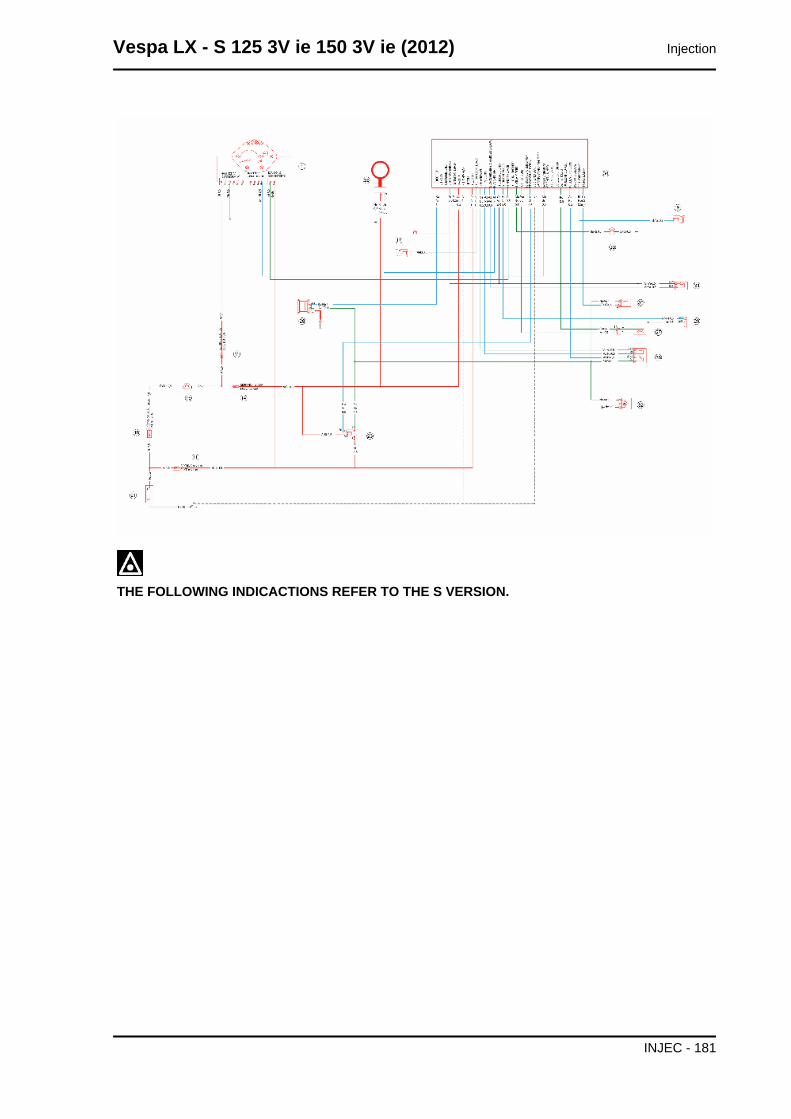
THE FOLLOWING INDICACTIONS REFER TO THE S VERSION.
Vespa LX - S 125 3V ie 150 3V ie (2012) Injection
INJEC - 181
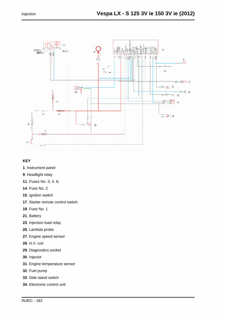
KEY
1. Instrument panel
9. Headlight relay
11. Fuses No. 3, 4, 6;
14. Fuse No. 2
15. Ignition switch
17. Starter remote control switch
18. Fuse No. 1
21. Battery
23. Injection load relay
26. Lambda probe
27. Engine speed sensor
28. H.V. coil
29. Diagnostics socket
30. Injector
31. Engine temperature sensor
32. Fuel pump
33. Side stand switch
34. Electronic control unit
Injection Vespa LX - S 125 3V ie 150 3V ie (2012)
INJEC - 182
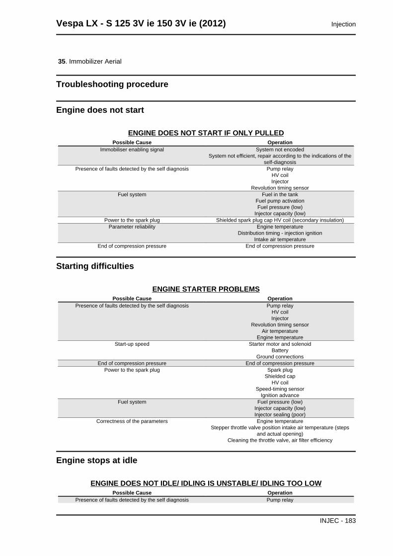
35. Immobilizer Aerial
Troubleshooting procedure
Engine does not start
ENGINE DOES NOT START IF ONLY PULLEDPossible Cause Operation
Immobiliser enabling signal System not encodedSystem not efficient, repair according to the indications of the
self-diagnosisPresence of faults detected by the self diagnosis Pump relay
HV coilInjector
Revolution timing sensorFuel system Fuel in the tank
Fuel pump activationFuel pressure (low)
Injector capacity (low)Power to the spark plug Shielded spark plug cap HV coil (secondary insulation)
Parameter reliability Engine temperatureDistribution timing - injection ignition
Intake air temperatureEnd of compression pressure End of compression pressure
Starting difficulties
ENGINE STARTER PROBLEMSPossible Cause Operation
Presence of faults detected by the self diagnosis Pump relayHV coilInjector
Revolution timing sensorAir temperature
Engine temperatureStart-up speed Starter motor and solenoid
BatteryGround connections
End of compression pressure End of compression pressurePower to the spark plug Spark plug
Shielded capHV coil
Speed-timing sensorIgnition advance
Fuel system Fuel pressure (low)Injector capacity (low)Injector sealing (poor)
Correctness of the parameters Engine temperatureStepper throttle valve position intake air temperature (steps
and actual opening)Cleaning the throttle valve, air filter efficiency
Engine stops at idle
ENGINE DOES NOT IDLE/ IDLING IS UNSTABLE/ IDLING TOO LOWPossible Cause Operation
Presence of faults detected by the self diagnosis Pump relay
Vespa LX - S 125 3V ie 150 3V ie (2012) Injection
INJEC - 183
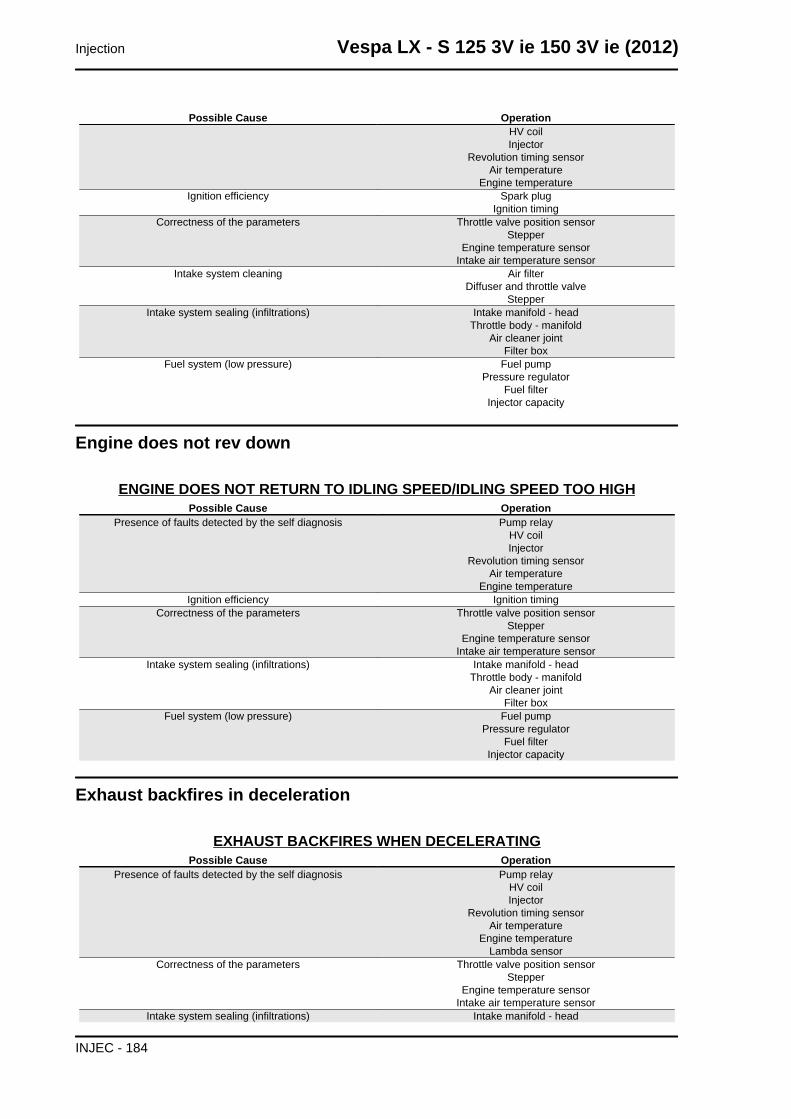
Possible Cause OperationHV coilInjector
Revolution timing sensorAir temperature
Engine temperatureIgnition efficiency Spark plug
Ignition timingCorrectness of the parameters Throttle valve position sensor
StepperEngine temperature sensor
Intake air temperature sensorIntake system cleaning Air filter
Diffuser and throttle valveStepper
Intake system sealing (infiltrations) Intake manifold - headThrottle body - manifold
Air cleaner jointFilter box
Fuel system (low pressure) Fuel pumpPressure regulator
Fuel filterInjector capacity
Engine does not rev down
ENGINE DOES NOT RETURN TO IDLING SPEED/IDLING SPEED TOO HIGHPossible Cause Operation
Presence of faults detected by the self diagnosis Pump relayHV coilInjector
Revolution timing sensorAir temperature
Engine temperatureIgnition efficiency Ignition timing
Correctness of the parameters Throttle valve position sensorStepper
Engine temperature sensorIntake air temperature sensor
Intake system sealing (infiltrations) Intake manifold - headThrottle body - manifold
Air cleaner jointFilter box
Fuel system (low pressure) Fuel pumpPressure regulator
Fuel filterInjector capacity
Exhaust backfires in deceleration
EXHAUST BACKFIRES WHEN DECELERATINGPossible Cause Operation
Presence of faults detected by the self diagnosis Pump relayHV coilInjector
Revolution timing sensorAir temperature
Engine temperatureLambda sensor
Correctness of the parameters Throttle valve position sensorStepper
Engine temperature sensorIntake air temperature sensor
Intake system sealing (infiltrations) Intake manifold - head
Injection Vespa LX - S 125 3V ie 150 3V ie (2012)
INJEC - 184
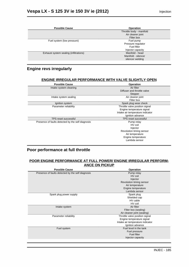
Possible Cause OperationThrottle body - manifold
Air cleaner jointFilter box
Fuel system (low pressure) Fuel pumpPressure regulator
Fuel filterInjector capacity
Exhaust system sealing (infiltrations) Manifold - headManifold - silencersilencer welding
Engine revs irregularly
ENGINE IRREGULAR PERFORMANCE WITH VALVE SLIGHTLY OPENPossible Cause Operation
Intake system cleaning Air filterDiffuser and throttle valve
StepperIntake system sealing Air cleaner joint
Filter boxIgnition system Spark plug wear check
Parameter reliability Throttle valve position signalEngine temperature signal
Intake air temperature indicatorIgnition advance
TPS reset successful TPS reset successfulPresence of faults detected by the self diagnosis Pump relay
HV coilInjector
Revolution timing sensorAir temperature
Engine temperatureLambda sensor
Poor performance at full throttle
POOR ENGINE PERFORMANCE AT FULL POWER/ ENGINE IRREGULAR PERFORM-ANCE ON PICKUP
Possible Cause OperationPresence of faults detected by the self diagnosis Pump relay
HV coilInjector
Revolution timing sensorAir temperature
Engine temperatureLambda sensor
Spark plug power supply Spark plugShielded cap
HV cableHV coil
Intake system Air filterFilter box (sealing)
Air cleaner joint (sealing)Parameter reliability Throttle valve position signal
Engine temperature signalIntake air temperature indicator
Ignition advanceFuel system Fuel level in the tank
Fuel pressureFuel filter
Injector capacity
Vespa LX - S 125 3V ie 150 3V ie (2012) Injection
INJEC - 185
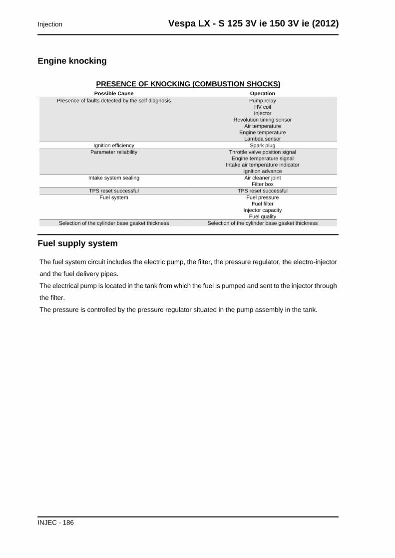
Engine knocking
PRESENCE OF KNOCKING (COMBUSTION SHOCKS)Possible Cause Operation
Presence of faults detected by the self diagnosis Pump relayHV coilInjector
Revolution timing sensorAir temperature
Engine temperatureLambda sensor
Ignition efficiency Spark plugParameter reliability Throttle valve position signal
Engine temperature signalIntake air temperature indicator
Ignition advanceIntake system sealing Air cleaner joint
Filter boxTPS reset successful TPS reset successful
Fuel system Fuel pressureFuel filter
Injector capacityFuel quality
Selection of the cylinder base gasket thickness Selection of the cylinder base gasket thickness
Fuel supply system
The fuel system circuit includes the electric pump, the filter, the pressure regulator, the electro-injector
and the fuel delivery pipes.
The electrical pump is located in the tank from which the fuel is pumped and sent to the injector through
the filter.
The pressure is controlled by the pressure regulator situated in the pump assembly in the tank.
Injection Vespa LX - S 125 3V ie 150 3V ie (2012)
INJEC - 186
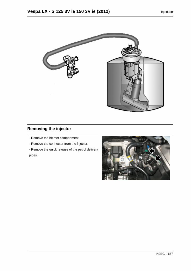
Removing the injector
- Remove the helmet compartment.
- Remove the connector from the injector.
- Remove the quick release of the petrol delivery
pipes.
Vespa LX - S 125 3V ie 150 3V ie (2012) Injection
INJEC - 187
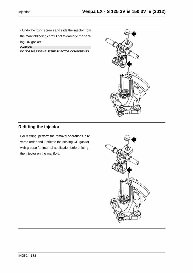
- Undo the fixing screws and slide the injector from
the manifold being careful not to damage the seal-
ing OR gasket.CAUTIONDO NOT DISASSEMBLE THE INJECTOR COMPONENTS.
Refitting the injector
For refitting, perform the removal operations in re-
verse order and lubricate the sealing OR gasket
with grease for internal application before fitting
the injector on the manifold.
Injection Vespa LX - S 125 3V ie 150 3V ie (2012)
INJEC - 188
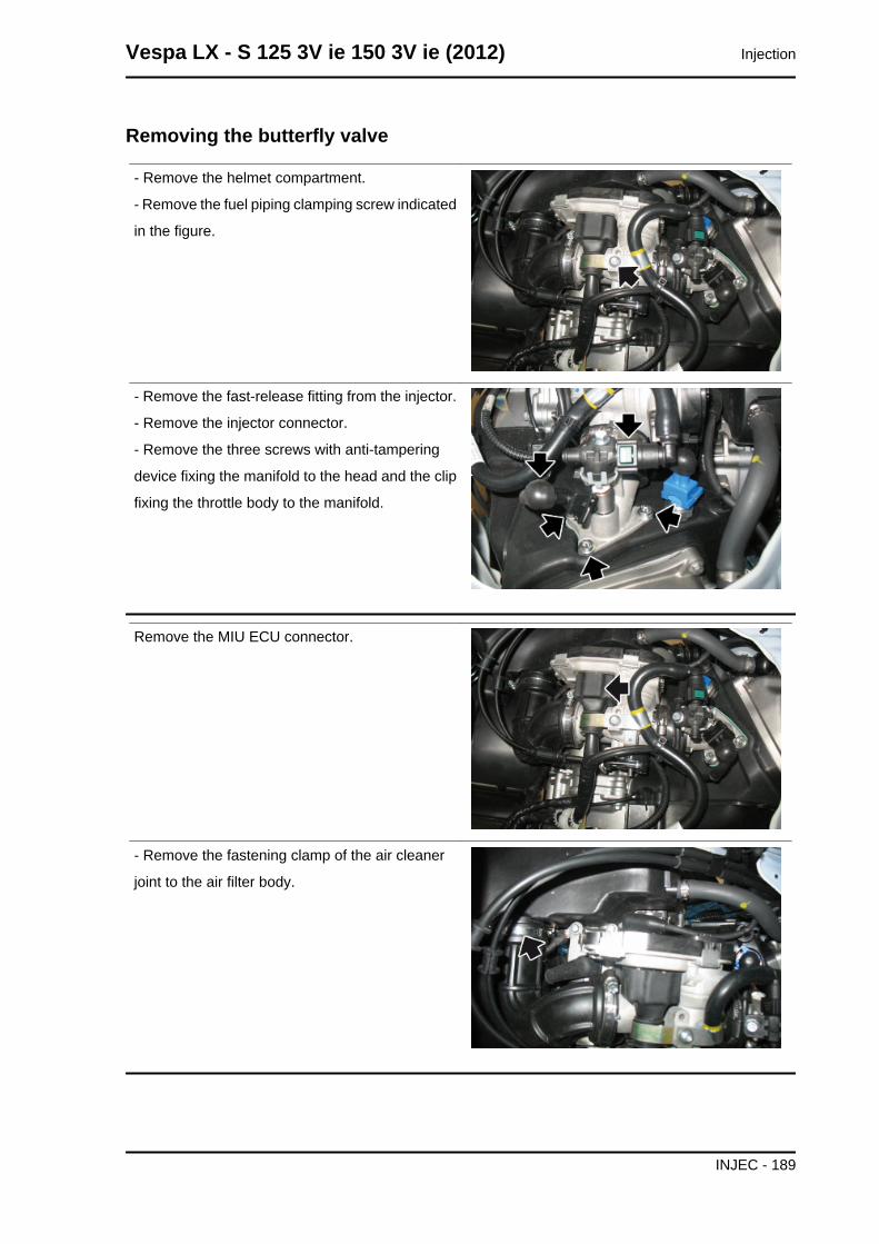
Removing the butterfly valve
- Remove the helmet compartment.
- Remove the fuel piping clamping screw indicated
in the figure.
- Remove the fast-release fitting from the injector.
- Remove the injector connector.
- Remove the three screws with anti-tampering
device fixing the manifold to the head and the clip
fixing the throttle body to the manifold.
Remove the MIU ECU connector.
- Remove the fastening clamp of the air cleaner
joint to the air filter body.
Vespa LX - S 125 3V ie 150 3V ie (2012) Injection
INJEC - 189
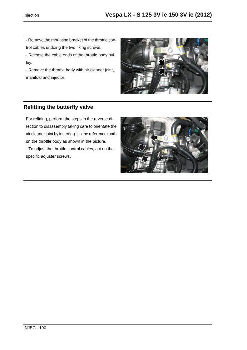
- Remove the mounting bracket of the throttle con-
trol cables undoing the two fixing screws.
- Release the cable ends of the throttle body pul-
ley.
- Remove the throttle body with air cleaner joint,
manifold and injector.
Refitting the butterfly valve
For refitting, perform the steps in the reverse di-
rection to disassembly taking care to orientate the
air cleaner joint by inserting it in the reference tooth
on the throttle body as shown in the picture.
- To adjust the throttle control cables, act on the
specific adjuster screws.
Injection Vespa LX - S 125 3V ie 150 3V ie (2012)
INJEC - 190
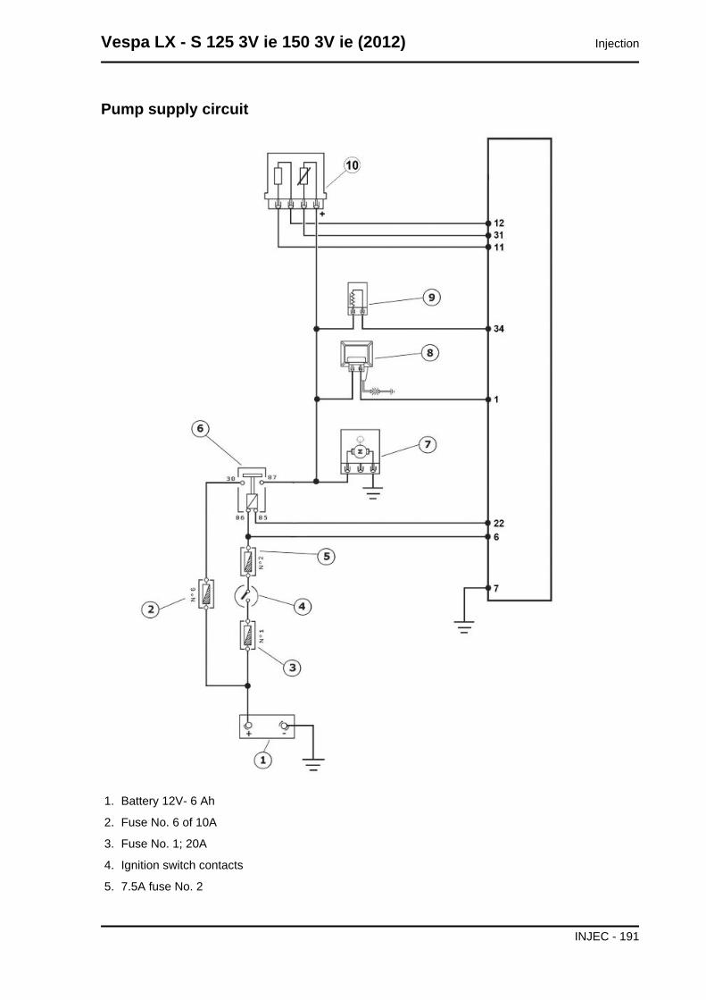
Pump supply circuit
1. Battery 12V- 6 Ah
2. Fuse No. 6 of 10A
3. Fuse No. 1; 20A
4. Ignition switch contacts
5. 7.5A fuse No. 2
Vespa LX - S 125 3V ie 150 3V ie (2012) Injection
INJEC - 191
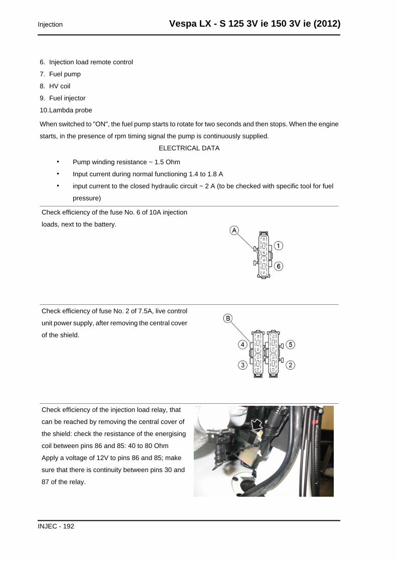
6. Injection load remote control
7. Fuel pump
8. HV coil
9. Fuel injector
10.Lambda probe
When switched to "ON", the fuel pump starts to rotate for two seconds and then stops. When the engine
starts, in the presence of rpm timing signal the pump is continuously supplied.
ELECTRICAL DATA
• Pump winding resistance ~ 1.5 Ohm
• Input current during normal functioning 1.4 to 1.8 A
• input current to the closed hydraulic circuit ~ 2 A (to be checked with specific tool for fuel
pressure)
Check efficiency of the fuse No. 6 of 10A injection
loads, next to the battery.
Check efficiency of fuse No. 2 of 7.5A, live control
unit power supply, after removing the central cover
of the shield.
Check efficiency of the injection load relay, that
can be reached by removing the central cover of
the shield: check the resistance of the energising
coil between pins 86 and 85: 40 to 80 Ohm
Apply a voltage of 12V to pins 86 and 85; make
sure that there is continuity between pins 30 and
87 of the relay.
Injection Vespa LX - S 125 3V ie 150 3V ie (2012)
INJEC - 192
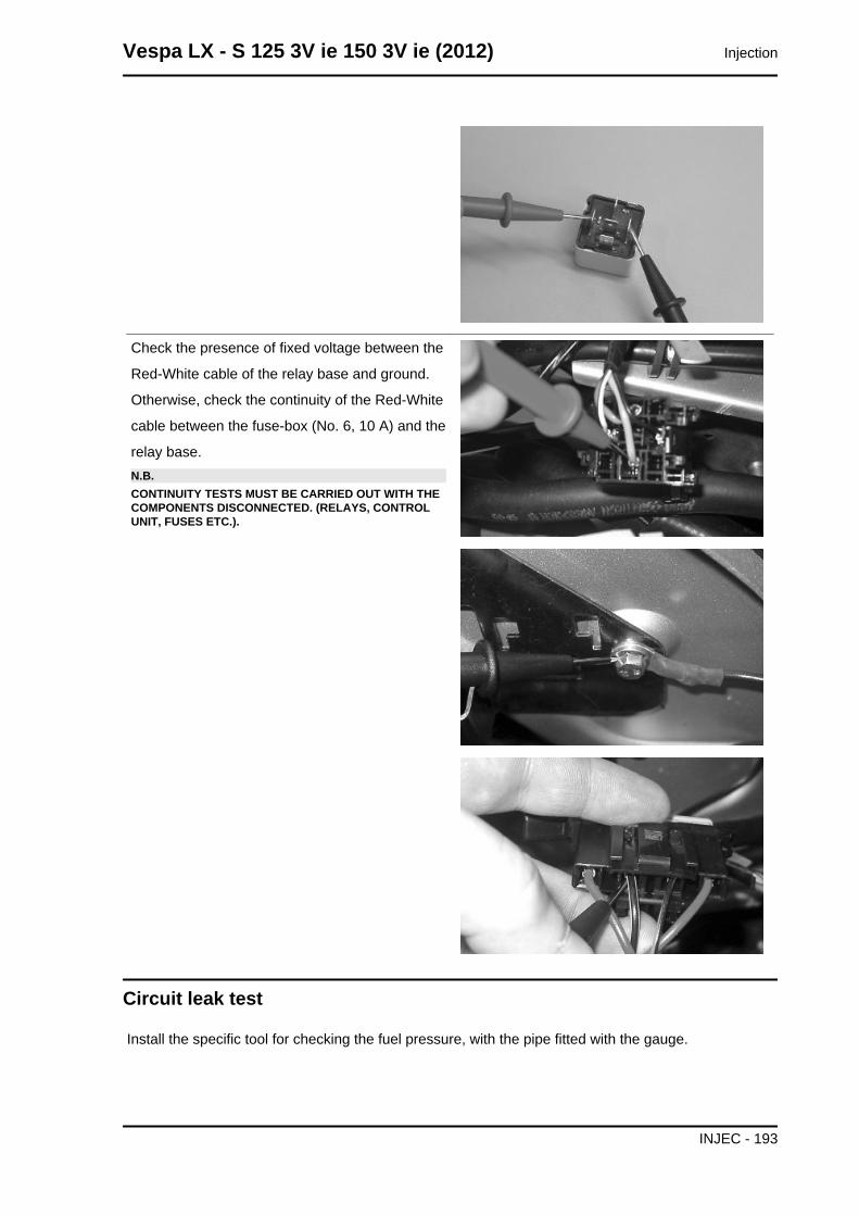
Check the presence of fixed voltage between the
Red-White cable of the relay base and ground.
Otherwise, check the continuity of the Red-White
cable between the fuse-box (No. 6, 10 A) and the
relay base.N.B.CONTINUITY TESTS MUST BE CARRIED OUT WITH THECOMPONENTS DISCONNECTED. (RELAYS, CONTROLUNIT, FUSES ETC.).
Circuit leak test
Install the specific tool for checking the fuel pressure, with the pipe fitted with the gauge.
Vespa LX - S 125 3V ie 150 3V ie (2012) Injection
INJEC - 193
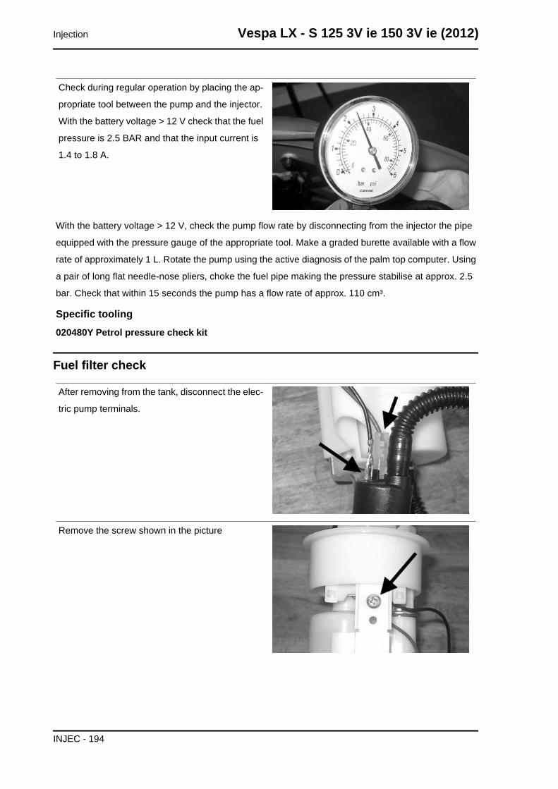
Check during regular operation by placing the ap-
propriate tool between the pump and the injector.
With the battery voltage > 12 V check that the fuel
pressure is 2.5 BAR and that the input current is
1.4 to 1.8 A.
With the battery voltage > 12 V, check the pump flow rate by disconnecting from the injector the pipe
equipped with the pressure gauge of the appropriate tool. Make a graded burette available with a flow
rate of approximately 1 L. Rotate the pump using the active diagnosis of the palm top computer. Using
a pair of long flat needle-nose pliers, choke the fuel pipe making the pressure stabilise at approx. 2.5
bar. Check that within 15 seconds the pump has a flow rate of approx. 110 cm³.
Specific tooling020480Y Petrol pressure check kit
Fuel filter check
After removing from the tank, disconnect the elec-
tric pump terminals.
Remove the screw shown in the picture
Injection Vespa LX - S 125 3V ie 150 3V ie (2012)
INJEC - 194
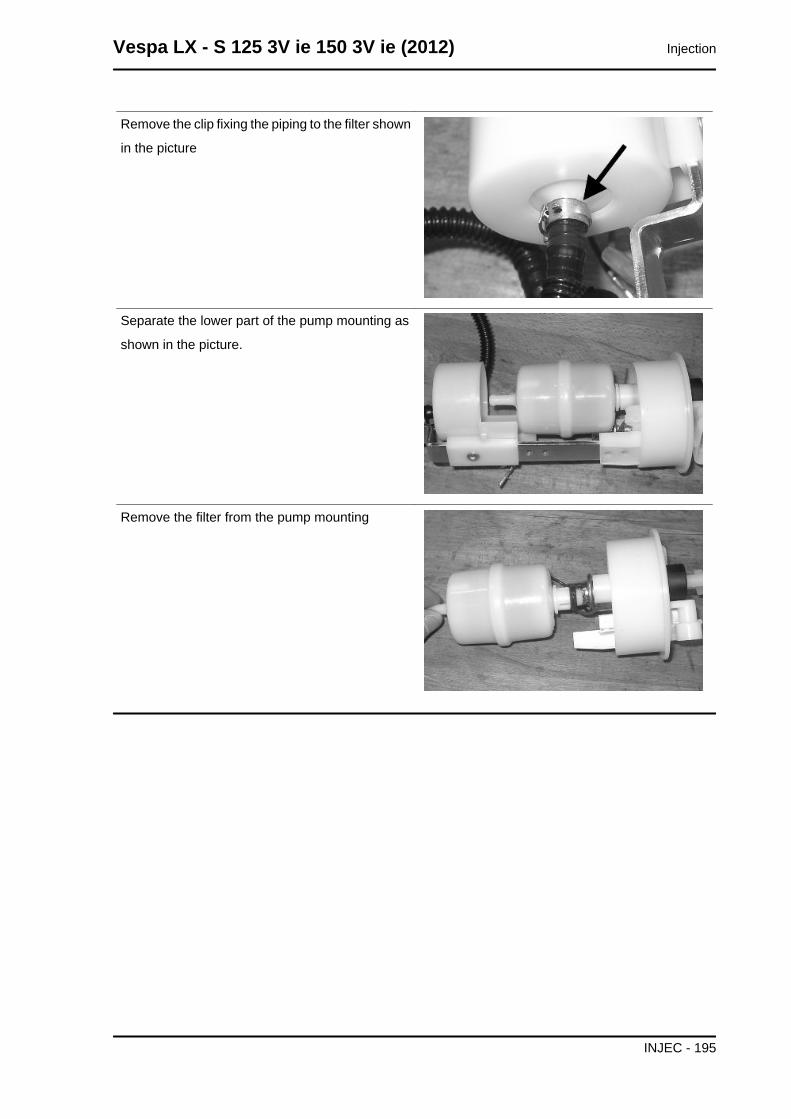
Remove the clip fixing the piping to the filter shown
in the picture
Separate the lower part of the pump mounting as
shown in the picture.
Remove the filter from the pump mounting
Vespa LX - S 125 3V ie 150 3V ie (2012) Injection
INJEC - 195
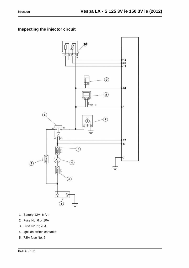
Inspecting the injector circuit
1. Battery 12V- 6 Ah
2. Fuse No. 6 of 10A
3. Fuse No. 1; 20A
4. Ignition switch contacts
5. 7.5A fuse No. 2
Injection Vespa LX - S 125 3V ie 150 3V ie (2012)
INJEC - 196
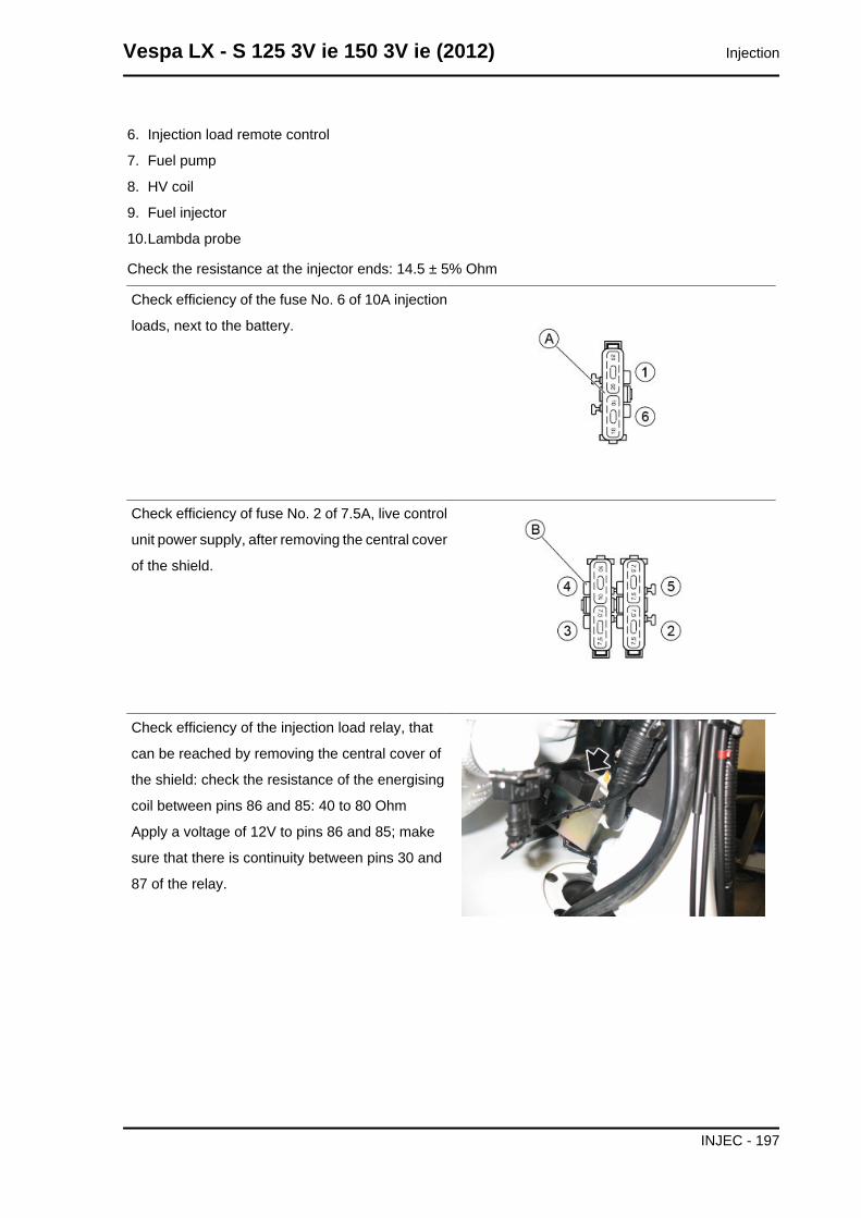
6. Injection load remote control
7. Fuel pump
8. HV coil
9. Fuel injector
10.Lambda probe
Check the resistance at the injector ends: 14.5 ± 5% Ohm
Check efficiency of the fuse No. 6 of 10A injection
loads, next to the battery.
Check efficiency of fuse No. 2 of 7.5A, live control
unit power supply, after removing the central cover
of the shield.
Check efficiency of the injection load relay, that
can be reached by removing the central cover of
the shield: check the resistance of the energising
coil between pins 86 and 85: 40 to 80 Ohm
Apply a voltage of 12V to pins 86 and 85; make
sure that there is continuity between pins 30 and
87 of the relay.
Vespa LX - S 125 3V ie 150 3V ie (2012) Injection
INJEC - 197
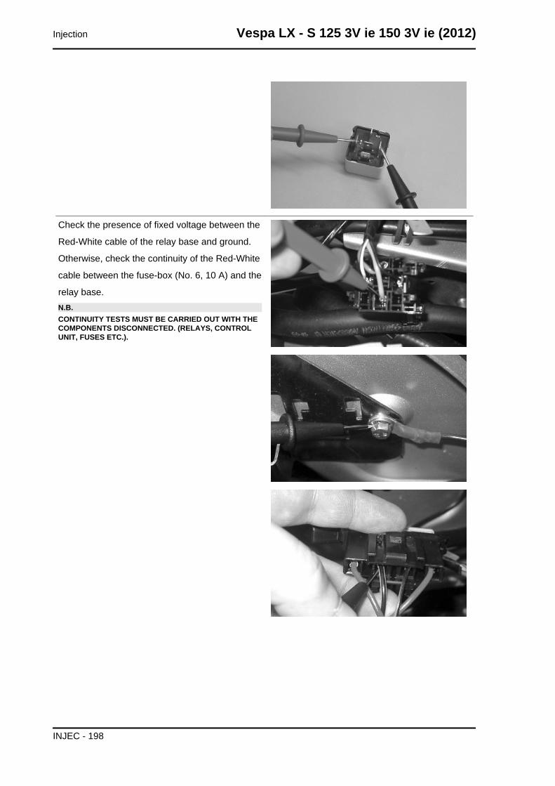
Check the presence of fixed voltage between the
Red-White cable of the relay base and ground.
Otherwise, check the continuity of the Red-White
cable between the fuse-box (No. 6, 10 A) and the
relay base.N.B.CONTINUITY TESTS MUST BE CARRIED OUT WITH THECOMPONENTS DISCONNECTED. (RELAYS, CONTROLUNIT, FUSES ETC.).
Injection Vespa LX - S 125 3V ie 150 3V ie (2012)
INJEC - 198
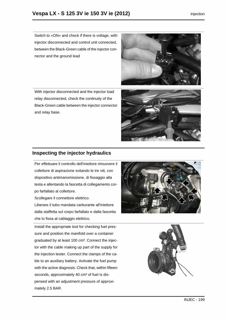
Switch to «ON» and check if there is voltage, with
injector disconnected and control unit connected,
between the Black-Green cable of the injector con-
nector and the ground lead
With injector disconnected and the injector load
relay disconnected, check the continuity of the
Black-Green cable between the injector connector
and relay base.
Inspecting the injector hydraulics
Per effettuare il controllo dell'iniettore rimuovere il
collettore di aspirazione svitando le tre viti, con
dispositivo antimanomissione, di fissaggio alla
testa e allentando la fascetta di collegamento cor-
po farfallato al collettore.
Scollegare il connettore elettrico.
Liberare il tubo mandata carburante all'iniettore
dalla staffetta sul corpo farfallato e dalla fascetta
che lo fissa al cablaggio elettrico.
Install the appropriate tool for checking fuel pres-
sure and position the manifold over a container
graduated by at least 100 cm³. Connect the injec-
tor with the cable making up part of the supply for
the injection tester. Connect the clamps of the ca-
ble to an auxiliary battery. Activate the fuel pump
with the active diagnosis. Check that, within fifteen
seconds, approximately 40 cm³ of fuel is dis-
pensed with an adjustment pressure of approxi-
mately 2.5 BAR.
Vespa LX - S 125 3V ie 150 3V ie (2012) Injection
INJEC - 199
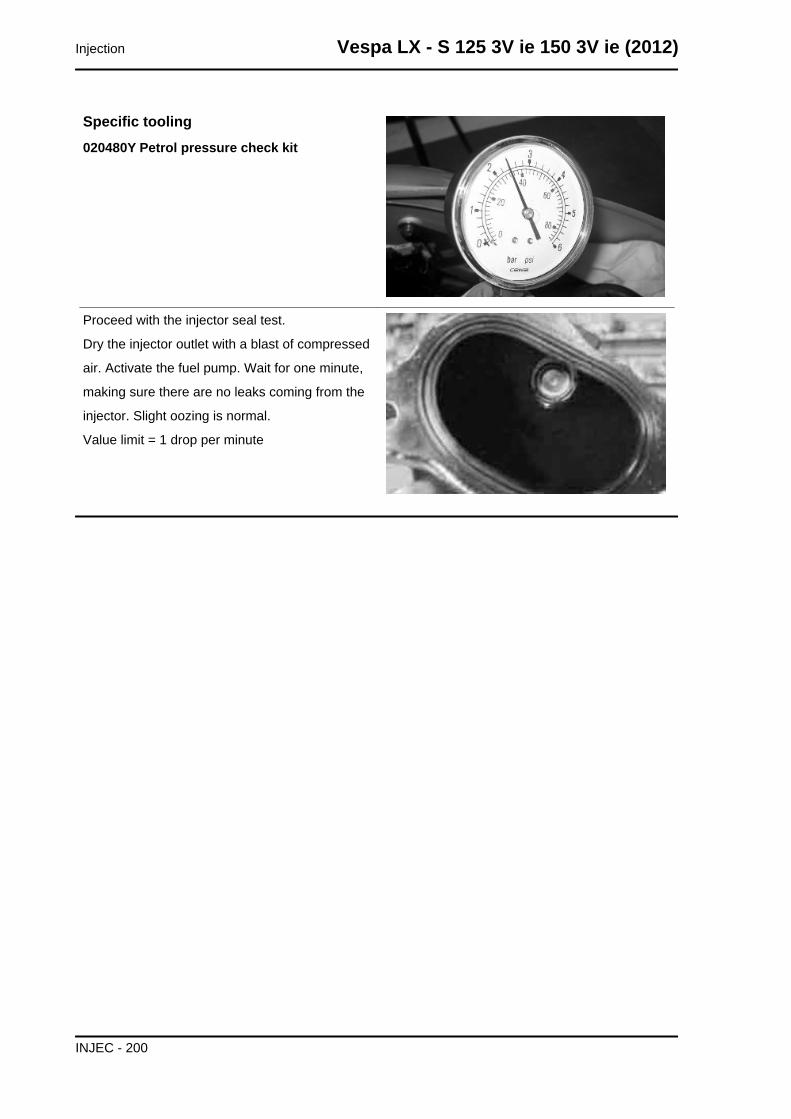
Specific tooling020480Y Petrol pressure check kit
Proceed with the injector seal test.
Dry the injector outlet with a blast of compressed
air. Activate the fuel pump. Wait for one minute,
making sure there are no leaks coming from the
injector. Slight oozing is normal.
Value limit = 1 drop per minute
Injection Vespa LX - S 125 3V ie 150 3V ie (2012)
INJEC - 200
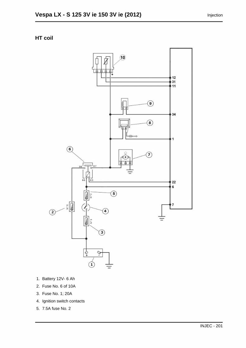
HT coil
1. Battery 12V- 6 Ah
2. Fuse No. 6 of 10A
3. Fuse No. 1; 20A
4. Ignition switch contacts
5. 7.5A fuse No. 2
Vespa LX - S 125 3V ie 150 3V ie (2012) Injection
INJEC - 201
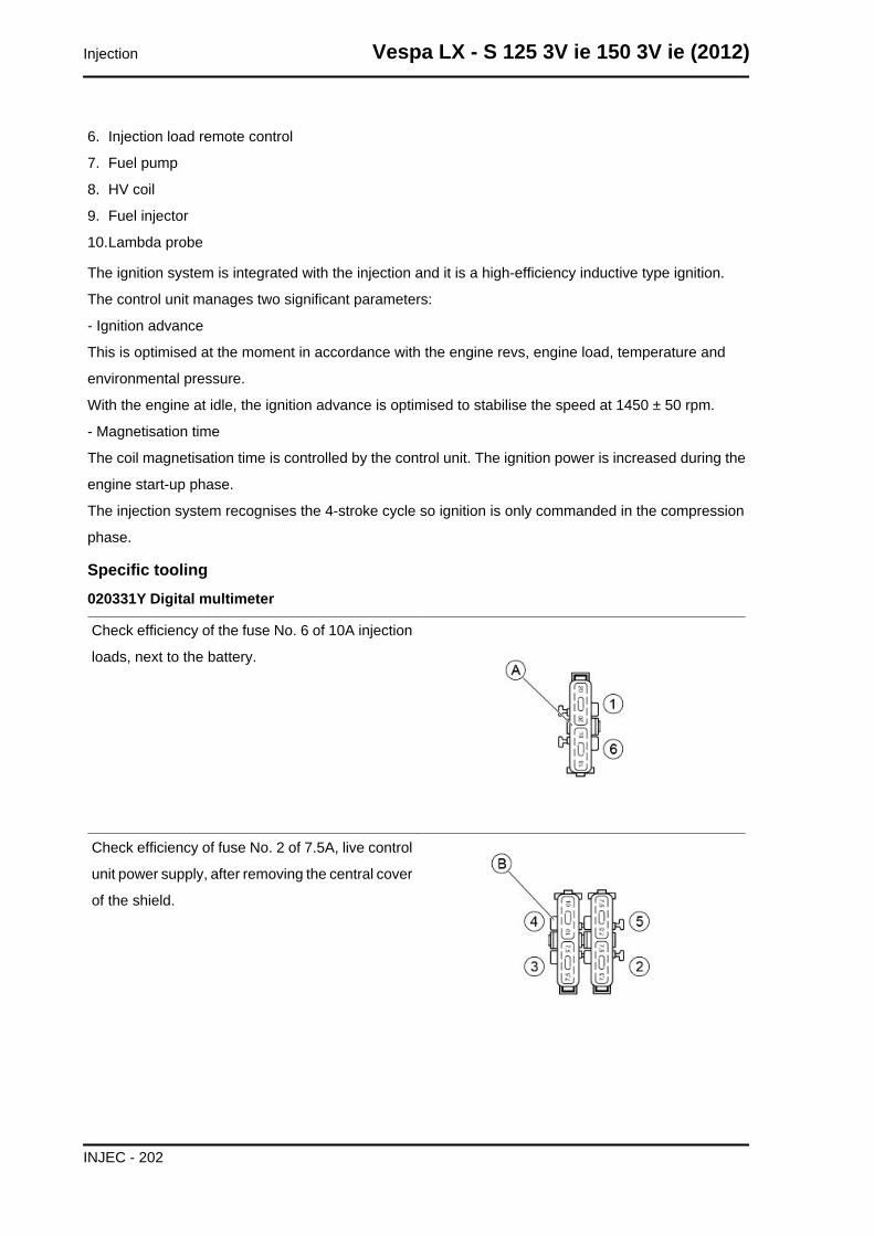
6. Injection load remote control
7. Fuel pump
8. HV coil
9. Fuel injector
10.Lambda probe
The ignition system is integrated with the injection and it is a high-efficiency inductive type ignition.
The control unit manages two significant parameters:
- Ignition advance
This is optimised at the moment in accordance with the engine revs, engine load, temperature and
environmental pressure.
With the engine at idle, the ignition advance is optimised to stabilise the speed at 1450 ± 50 rpm.
- Magnetisation time
The coil magnetisation time is controlled by the control unit. The ignition power is increased during the
engine start-up phase.
The injection system recognises the 4-stroke cycle so ignition is only commanded in the compression
phase.
Specific tooling020331Y Digital multimeter
Check efficiency of the fuse No. 6 of 10A injection
loads, next to the battery.
Check efficiency of fuse No. 2 of 7.5A, live control
unit power supply, after removing the central cover
of the shield.
Injection Vespa LX - S 125 3V ie 150 3V ie (2012)
INJEC - 202
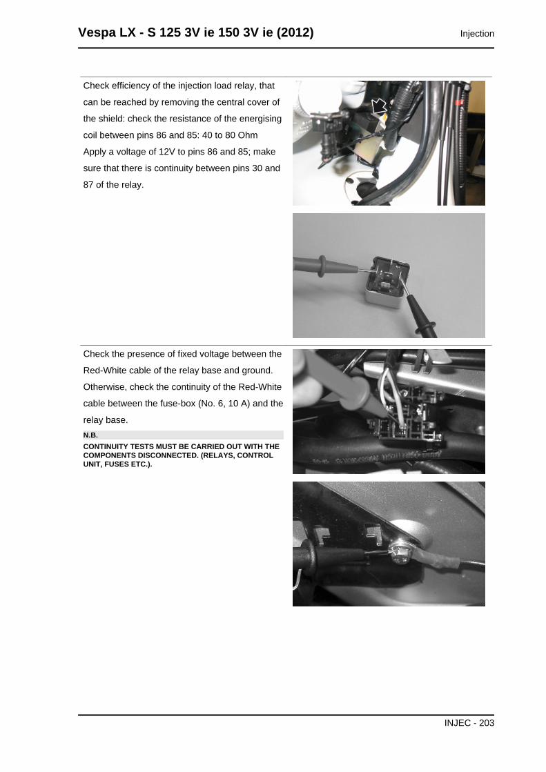
Check efficiency of the injection load relay, that
can be reached by removing the central cover of
the shield: check the resistance of the energising
coil between pins 86 and 85: 40 to 80 Ohm
Apply a voltage of 12V to pins 86 and 85; make
sure that there is continuity between pins 30 and
87 of the relay.
Check the presence of fixed voltage between the
Red-White cable of the relay base and ground.
Otherwise, check the continuity of the Red-White
cable between the fuse-box (No. 6, 10 A) and the
relay base.N.B.CONTINUITY TESTS MUST BE CARRIED OUT WITH THECOMPONENTS DISCONNECTED. (RELAYS, CONTROLUNIT, FUSES ETC.).
Vespa LX - S 125 3V ie 150 3V ie (2012) Injection
INJEC - 203
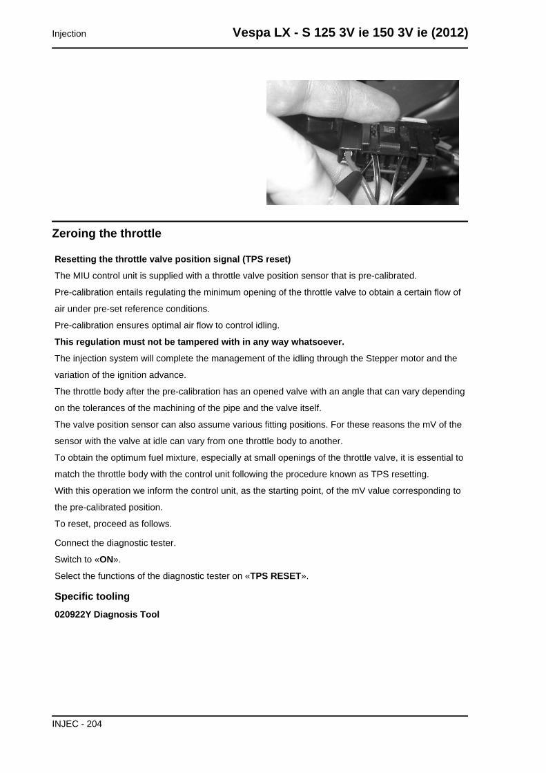
Zeroing the throttle
Resetting the throttle valve position signal (TPS reset)
The MIU control unit is supplied with a throttle valve position sensor that is pre-calibrated.
Pre-calibration entails regulating the minimum opening of the throttle valve to obtain a certain flow of
air under pre-set reference conditions.
Pre-calibration ensures optimal air flow to control idling.
This regulation must not be tampered with in any way whatsoever.
The injection system will complete the management of the idling through the Stepper motor and the
variation of the ignition advance.
The throttle body after the pre-calibration has an opened valve with an angle that can vary depending
on the tolerances of the machining of the pipe and the valve itself.
The valve position sensor can also assume various fitting positions. For these reasons the mV of the
sensor with the valve at idle can vary from one throttle body to another.
To obtain the optimum fuel mixture, especially at small openings of the throttle valve, it is essential to
match the throttle body with the control unit following the procedure known as TPS resetting.
With this operation we inform the control unit, as the starting point, of the mV value corresponding to
the pre-calibrated position.
To reset, proceed as follows.
Connect the diagnostic tester.
Switch to «ON».
Select the functions of the diagnostic tester on «TPS RESET».
Specific tooling020922Y Diagnosis Tool
Injection Vespa LX - S 125 3V ie 150 3V ie (2012)
INJEC - 204
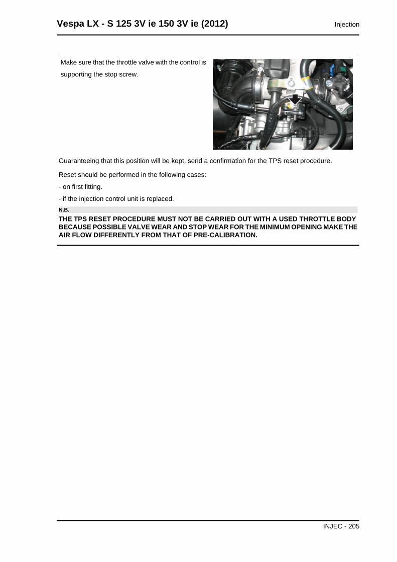
Make sure that the throttle valve with the control is
supporting the stop screw.
Guaranteeing that this position will be kept, send a confirmation for the TPS reset procedure.
Reset should be performed in the following cases:
- on first fitting.
- if the injection control unit is replaced.N.B.
THE TPS RESET PROCEDURE MUST NOT BE CARRIED OUT WITH A USED THROTTLE BODYBECAUSE POSSIBLE VALVE WEAR AND STOP WEAR FOR THE MINIMUM OPENING MAKE THEAIR FLOW DIFFERENTLY FROM THAT OF PRE-CALIBRATION.
Vespa LX - S 125 3V ie 150 3V ie (2012) Injection
INJEC - 205
INDEX OF TOPICS
SUSPENSIONS SUSP
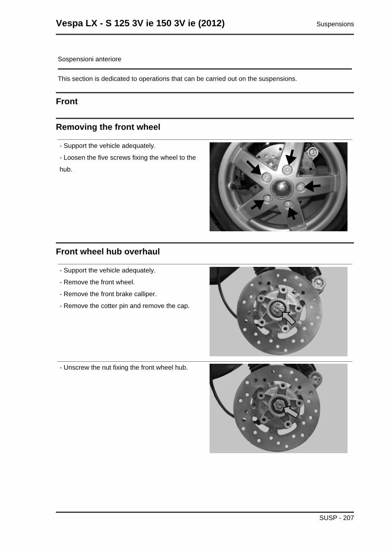
Sospensioni anteriore
This section is dedicated to operations that can be carried out on the suspensions.
Front
Removing the front wheel
- Support the vehicle adequately.
- Loosen the five screws fixing the wheel to the
hub.
Front wheel hub overhaul
- Support the vehicle adequately.
- Remove the front wheel.
- Remove the front brake calliper.
- Remove the cotter pin and remove the cap.
- Unscrew the nut fixing the front wheel hub.
Vespa LX - S 125 3V ie 150 3V ie (2012) Suspensions
SUSP - 207
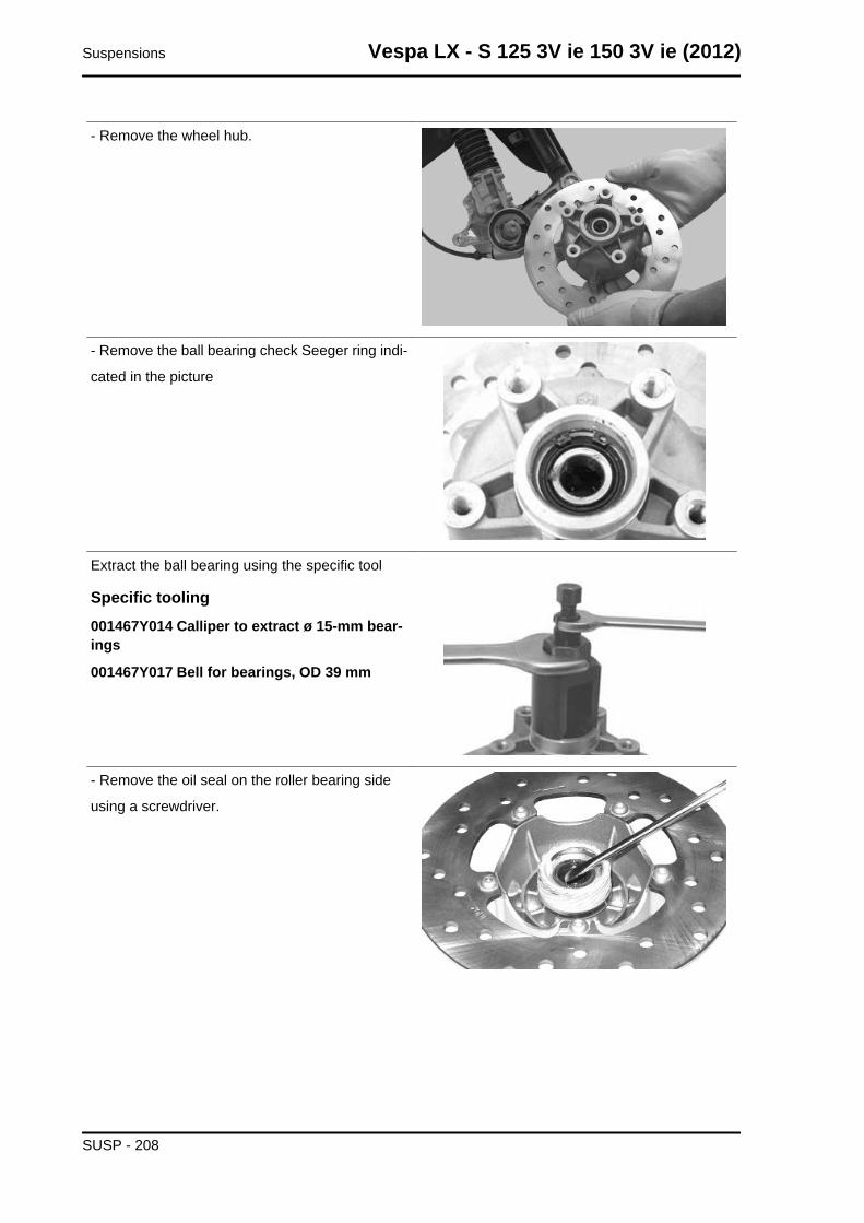
- Remove the wheel hub.
- Remove the ball bearing check Seeger ring indi-
cated in the picture
Extract the ball bearing using the specific tool
Specific tooling001467Y014 Calliper to extract ø 15-mm bear-ings
001467Y017 Bell for bearings, OD 39 mm
- Remove the oil seal on the roller bearing side
using a screwdriver.
Suspensions Vespa LX - S 125 3V ie 150 3V ie (2012)
SUSP - 208
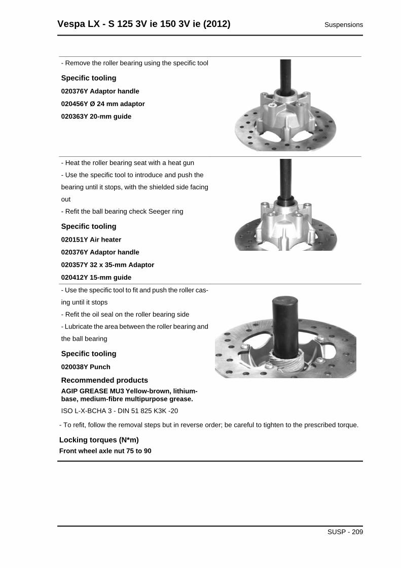
- Remove the roller bearing using the specific tool
Specific tooling020376Y Adaptor handle
020456Y Ø 24 mm adaptor
020363Y 20-mm guide
- Heat the roller bearing seat with a heat gun
- Use the specific tool to introduce and push the
bearing until it stops, with the shielded side facing
out
- Refit the ball bearing check Seeger ring
Specific tooling020151Y Air heater
020376Y Adaptor handle
020357Y 32 x 35-mm Adaptor
020412Y 15-mm guide
- Use the specific tool to fit and push the roller cas-
ing until it stops
- Refit the oil seal on the roller bearing side
- Lubricate the area between the roller bearing and
the ball bearing
Specific tooling020038Y Punch
Recommended productsAGIP GREASE MU3 Yellow-brown, lithium-base, medium-fibre multipurpose grease.ISO L-X-BCHA 3 - DIN 51 825 K3K -20
- To refit, follow the removal steps but in reverse order; be careful to tighten to the prescribed torque.
Locking torques (N*m)Front wheel axle nut 75 to 90
Vespa LX - S 125 3V ie 150 3V ie (2012) Suspensions
SUSP - 209

Refitting the front wheel
- Upon refitting, tighten the five screws to the pre-
scribed torque.
Locking torques (N*m)Wheel rim screws 20 to 25
Handlebar
Removal
Remove the handlebar cover before carrying out
this operation,.
- After removing the transmissions and discon-
necting the electrical terminals, remove the termi-
nal fixing the handlebar to the steering.
- Check all components and replace faulty parts.N.B.IF THE HANDLEBAR IS BEING REMOVED TO REMOVETHE STEERING, TILT THE HANDLEBAR FORWARD TOAVOIDING DAMAGING THE TRANSMISSIONS.WARNING
DO NOT LEAVE THE REMOVED INSTRUMENT DANGLINGOR UPSIDE DOWN AS THIS COULD DAMAGE IT IRREP-ARABLY. FAILURE TO OBSERVE THIS INSTRUCTIONCAUSES THE LOSS OF CALIBRATION OF THE INSTRU-MENT PANEL WHICH, ALTHOUGH OPERATIONAL, INDI-CATES INCORRECT VALUES.
Suspensions Vespa LX - S 125 3V ie 150 3V ie (2012)
SUSP - 210
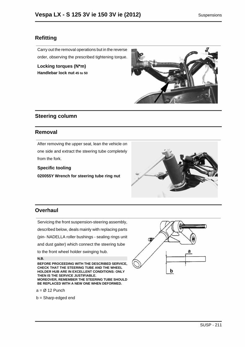
Refitting
Carry out the removal operations but in the reverse
order, observing the prescribed tightening torque.
Locking torques (N*m)Handlebar lock nut 45 to 50
Steering column
Removal
After removing the upper seat, lean the vehicle on
one side and extract the steering tube completely
from the fork.
Specific tooling020055Y Wrench for steering tube ring nut
Overhaul
Servicing the front suspension-steering assembly,
described below, deals mainly with replacing parts
(pin- NADELLA roller bushings - sealing rings unit
and dust gaiter) which connect the steering tube
to the front wheel holder swinging hub.N.B.BEFORE PROCEEDING WITH THE DESCRIBED SERVICE,CHECK THAT THE STEERING TUBE AND THE WHEELHOLDER HUB ARE IN EXCELLENT CONDITIONS: ONLYTHEN IS THE SERVICE JUSTIFIABLE.MOREOVER, REMEMBER THE STEERING TUBE SHOULDBE REPLACED WITH A NEW ONE WHEN DEFORMED.
a = Ø 12 Punch
b = Sharp-edged end
Vespa LX - S 125 3V ie 150 3V ie (2012) Suspensions
SUSP - 211
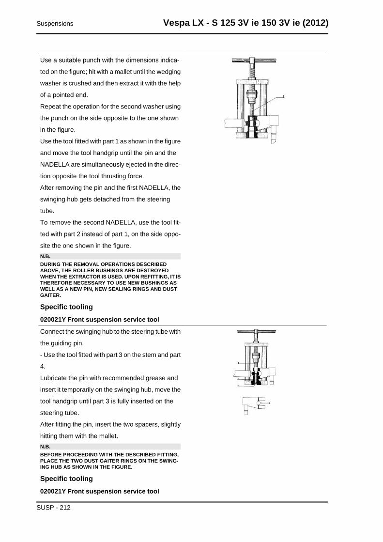
Use a suitable punch with the dimensions indica-
ted on the figure; hit with a mallet until the wedging
washer is crushed and then extract it with the help
of a pointed end.
Repeat the operation for the second washer using
the punch on the side opposite to the one shown
in the figure.
Use the tool fitted with part 1 as shown in the figure
and move the tool handgrip until the pin and the
NADELLA are simultaneously ejected in the direc-
tion opposite the tool thrusting force.
After removing the pin and the first NADELLA, the
swinging hub gets detached from the steering
tube.
To remove the second NADELLA, use the tool fit-
ted with part 2 instead of part 1, on the side oppo-
site the one shown in the figure.N.B.DURING THE REMOVAL OPERATIONS DESCRIBEDABOVE, THE ROLLER BUSHINGS ARE DESTROYEDWHEN THE EXTRACTOR IS USED. UPON REFITTING, IT ISTHEREFORE NECESSARY TO USE NEW BUSHINGS ASWELL AS A NEW PIN, NEW SEALING RINGS AND DUSTGAITER.
Specific tooling020021Y Front suspension service tool
Connect the swinging hub to the steering tube with
the guiding pin.
- Use the tool fitted with part 3 on the stem and part
4.
Lubricate the pin with recommended grease and
insert it temporarily on the swinging hub, move the
tool handgrip until part 3 is fully inserted on the
steering tube.
After fitting the pin, insert the two spacers, slightly
hitting them with the mallet.N.B.BEFORE PROCEEDING WITH THE DESCRIBED FITTING,PLACE THE TWO DUST GAITER RINGS ON THE SWING-ING HUB AS SHOWN IN THE FIGURE.
Specific tooling020021Y Front suspension service tool
Suspensions Vespa LX - S 125 3V ie 150 3V ie (2012)
SUSP - 212
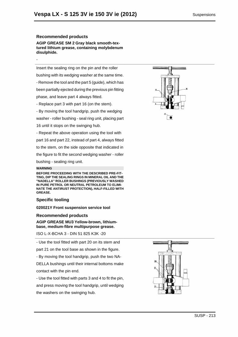
Recommended productsAGIP GREASE SM 2 Gray black smooth-tex-tured lithium grease, containing molybdenumdisulphide.-
Insert the sealing ring on the pin and the roller
bushing with its wedging washer at the same time.
- Remove the tool and the part 5 (guide), which has
been partially ejected during the previous pin fitting
phase, and leave part 4 always fitted.
- Replace part 3 with part 16 (on the stem).
- By moving the tool handgrip, push the wedging
washer - roller bushing - seal ring unit, placing part
16 until it stops on the swinging hub.
- Repeat the above operation using the tool with
part 16 and part 22, instead of part 4, always fitted
to the stem, on the side opposite that indicated in
the figure to fit the second wedging washer - roller
bushing - sealing ring unit.WARNINGBEFORE PROCEEDING WITH THE DESCRIBED PRE-FIT-TING, DIP THE SEALING RINGS IN MINERAL OIL AND THE"NADELLA" ROLLER BUSHINGS (PREVIOUSLY WASHEDIN PURE PETROL OR NEUTRAL PETROLEUM TO ELIMI-NATE THE ANTIRUST PROTECTION), HALF-FILLED WITHGREASE.
Specific tooling020021Y Front suspension service tool
Recommended productsAGIP GREASE MU3 Yellow-brown, lithium-base, medium-fibre multipurpose grease.ISO L-X-BCHA 3 - DIN 51 825 K3K -20
- Use the tool fitted with part 20 on its stem and
part 21 on the tool base as shown in the figure.
- By moving the tool handgrip, push the two NA-
DELLA bushings until their internal bottoms make
contact with the pin end.
- Use the tool fitted with parts 3 and 4 to fit the pin,
and press moving the tool handgrip, until wedging
the washers on the swinging hub.
Vespa LX - S 125 3V ie 150 3V ie (2012) Suspensions
SUSP - 213
- Now, remove the two spacers (parts 17 and 16)
and, once the space between the NADELLAs -
steering tube and swinging hub - has been fully
filled with grease, move the dust gaiter rings until
they are placed in that space.
- By wedging the washers as described above, the
front suspension unit refitting stage is finished.
Recommended productsAGIP GREASE MU3 Yellow-brown, lithium-base, medium-fibre multipurpose grease.ISO L-X-BCHA 3 - DIN 51 825 K3K -20
RefittingCAUTION
USE NEW ROLLER CASINGS, PIN, SEALING RINGS AND DUST GUARDS FOR REFITTING.
Suspensions Vespa LX - S 125 3V ie 150 3V ie (2012)
SUSP - 214
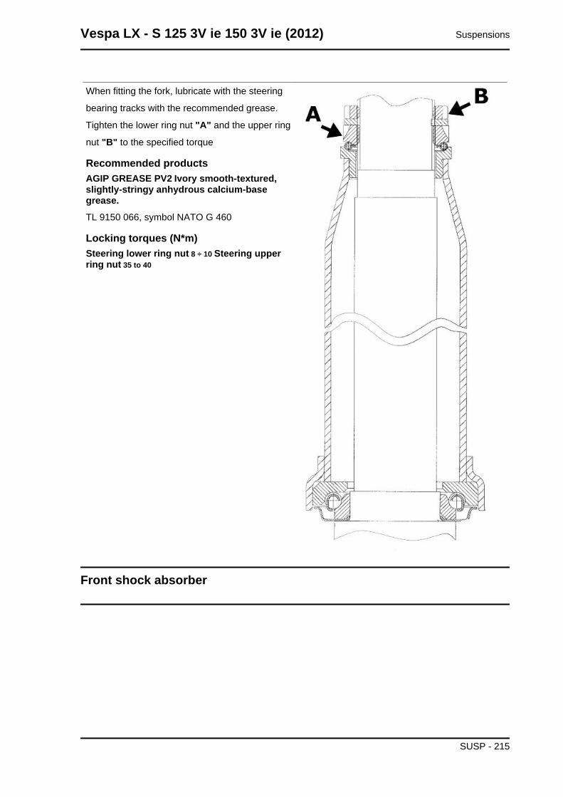
When fitting the fork, lubricate with the steering
bearing tracks with the recommended grease.
Tighten the lower ring nut "A" and the upper ring
nut "B" to the specified torque
Recommended productsAGIP GREASE PV2 Ivory smooth-textured,slightly-stringy anhydrous calcium-basegrease.TL 9150 066, symbol NATO G 460
Locking torques (N*m)Steering lower ring nut 8 ÷ 10 Steering upperring nut 35 to 40
Front shock absorber
Vespa LX - S 125 3V ie 150 3V ie (2012) Suspensions
SUSP - 215
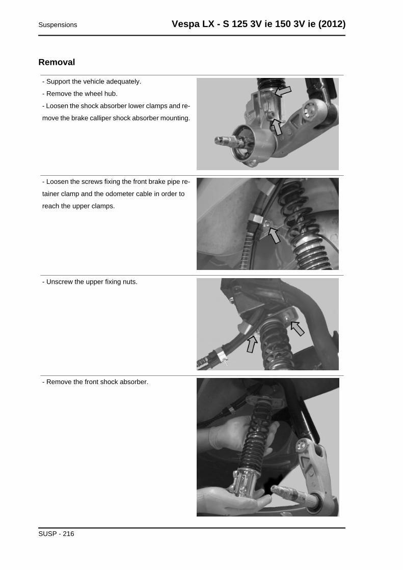
Removal
- Support the vehicle adequately.
- Remove the wheel hub.
- Loosen the shock absorber lower clamps and re-
move the brake calliper shock absorber mounting.
- Loosen the screws fixing the front brake pipe re-
tainer clamp and the odometer cable in order to
reach the upper clamps.
- Unscrew the upper fixing nuts.
- Remove the front shock absorber.
Suspensions Vespa LX - S 125 3V ie 150 3V ie (2012)
SUSP - 216
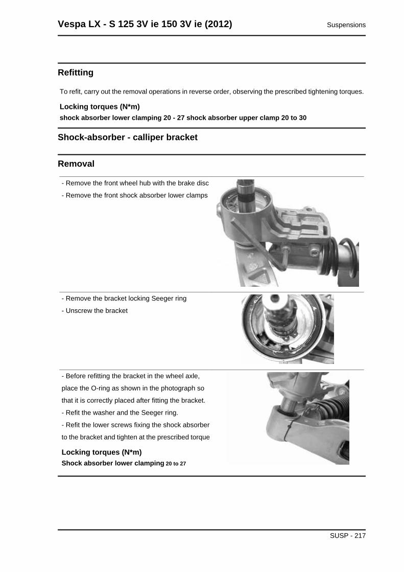
Refitting
To refit, carry out the removal operations in reverse order, observing the prescribed tightening torques.
Locking torques (N*m)shock absorber lower clamping 20 - 27 shock absorber upper clamp 20 to 30
Shock-absorber - calliper bracket
Removal
- Remove the front wheel hub with the brake disc
- Remove the front shock absorber lower clamps
- Remove the bracket locking Seeger ring
- Unscrew the bracket
- Before refitting the bracket in the wheel axle,
place the O-ring as shown in the photograph so
that it is correctly placed after fitting the bracket.
- Refit the washer and the Seeger ring.
- Refit the lower screws fixing the shock absorber
to the bracket and tighten at the prescribed torque
Locking torques (N*m)Shock absorber lower clamping 20 to 27
Vespa LX - S 125 3V ie 150 3V ie (2012) Suspensions
SUSP - 217

Overhaul
- The bracket for the shock absorber -calliper at-
tachment has two roller bearings separated one
from the other as shown in the photograph
- Remove the two roller bearings from the bracket
with the specific tool operating on the shock ab-
sorber attachment side as shown in the photo-
graph
Specific tooling020376Y Adaptor handle
020441Y 26 x 28 mm adaptor
020365Y 22 mm guide
- Remove the oil seal on the wheel hub side with
the screwdriver as shown in the photograph
- Suitably hold the brake calliper - shock absorber
attachment bracket
- Fit a new oil seal and move it until it stops using
the specific tool
Specific tooling020376Y Adaptor handle
020360Y 52 x 55-mm Adaptor
Suspensions Vespa LX - S 125 3V ie 150 3V ie (2012)
SUSP - 218
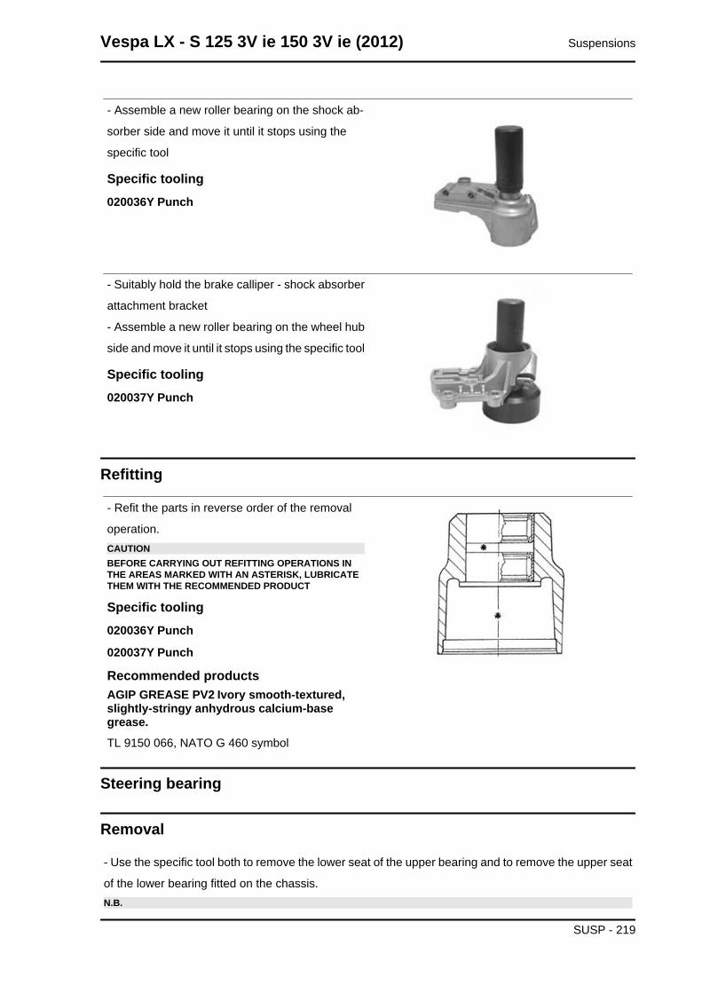
- Assemble a new roller bearing on the shock ab-
sorber side and move it until it stops using the
specific tool
Specific tooling020036Y Punch
- Suitably hold the brake calliper - shock absorber
attachment bracket
- Assemble a new roller bearing on the wheel hub
side and move it until it stops using the specific tool
Specific tooling020037Y Punch
Refitting
- Refit the parts in reverse order of the removal
operation.CAUTIONBEFORE CARRYING OUT REFITTING OPERATIONS INTHE AREAS MARKED WITH AN ASTERISK, LUBRICATETHEM WITH THE RECOMMENDED PRODUCT
Specific tooling020036Y Punch
020037Y Punch
Recommended productsAGIP GREASE PV2 Ivory smooth-textured,slightly-stringy anhydrous calcium-basegrease.TL 9150 066, NATO G 460 symbol
Steering bearing
Removal
- Use the specific tool both to remove the lower seat of the upper bearing and to remove the upper seat
of the lower bearing fitted on the chassis.N.B.
Vespa LX - S 125 3V ie 150 3V ie (2012) Suspensions
SUSP - 219
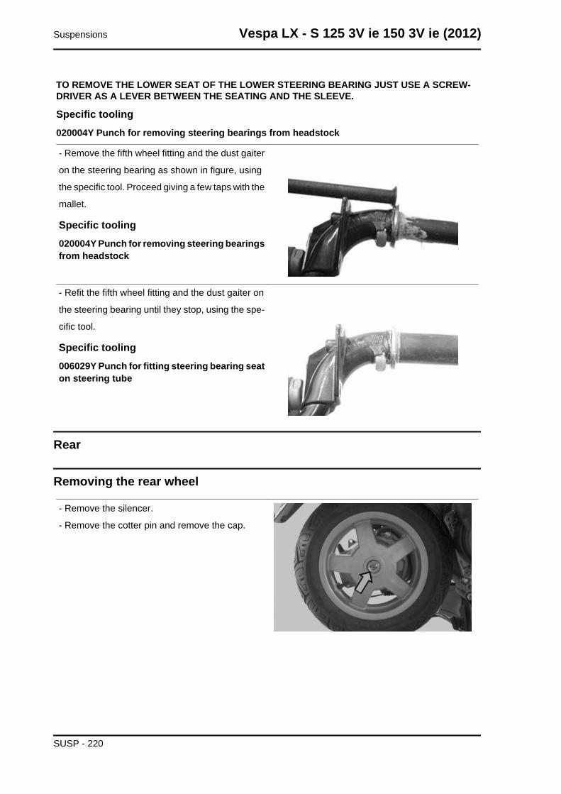
TO REMOVE THE LOWER SEAT OF THE LOWER STEERING BEARING JUST USE A SCREW-DRIVER AS A LEVER BETWEEN THE SEATING AND THE SLEEVE.
Specific tooling020004Y Punch for removing steering bearings from headstock
- Remove the fifth wheel fitting and the dust gaiter
on the steering bearing as shown in figure, using
the specific tool. Proceed giving a few taps with the
mallet.
Specific tooling020004Y Punch for removing steering bearingsfrom headstock
- Refit the fifth wheel fitting and the dust gaiter on
the steering bearing until they stop, using the spe-
cific tool.
Specific tooling006029Y Punch for fitting steering bearing seaton steering tube
Rear
Removing the rear wheel
- Remove the silencer.
- Remove the cotter pin and remove the cap.
Suspensions Vespa LX - S 125 3V ie 150 3V ie (2012)
SUSP - 220
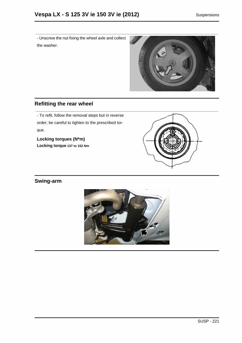
- Unscrew the nut fixing the wheel axle and collect
the washer.
Refitting the rear wheel
- To refit, follow the removal steps but in reverse
order; be careful to tighten to the prescribed tor-
que.
Locking torques (N*m)Locking torque 137 to 152 Nm
Swing-arm
Vespa LX - S 125 3V ie 150 3V ie (2012) Suspensions
SUSP - 221
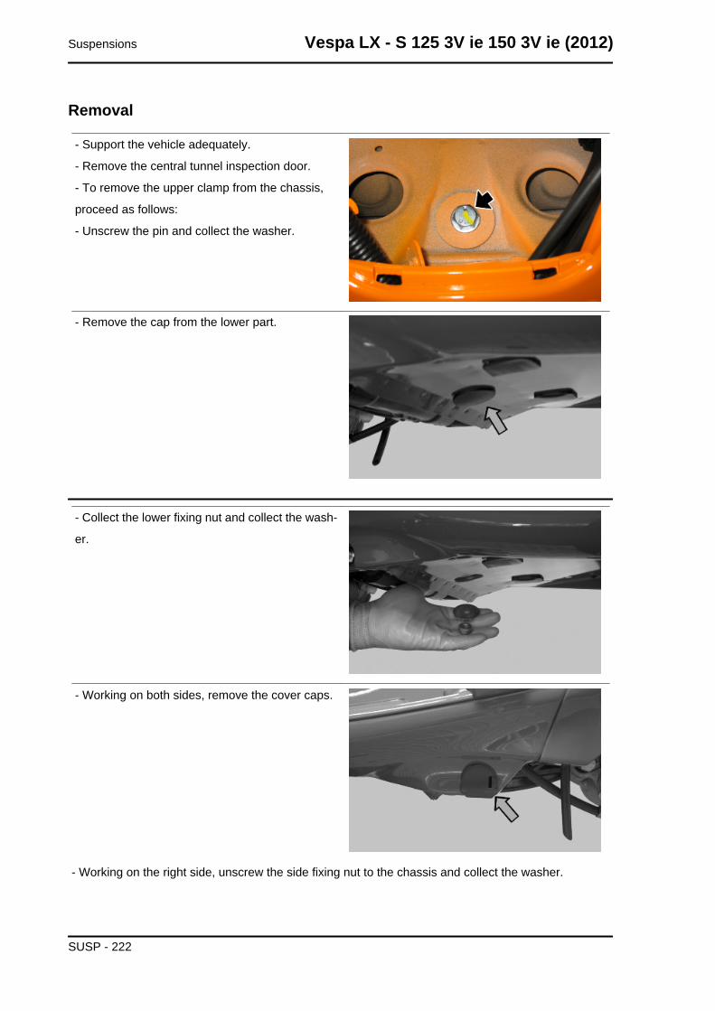
Removal
- Support the vehicle adequately.
- Remove the central tunnel inspection door.
- To remove the upper clamp from the chassis,
proceed as follows:
- Unscrew the pin and collect the washer.
- Remove the cap from the lower part.
- Collect the lower fixing nut and collect the wash-
er.
- Working on both sides, remove the cover caps.
- Working on the right side, unscrew the side fixing nut to the chassis and collect the washer.
Suspensions Vespa LX - S 125 3V ie 150 3V ie (2012)
SUSP - 222
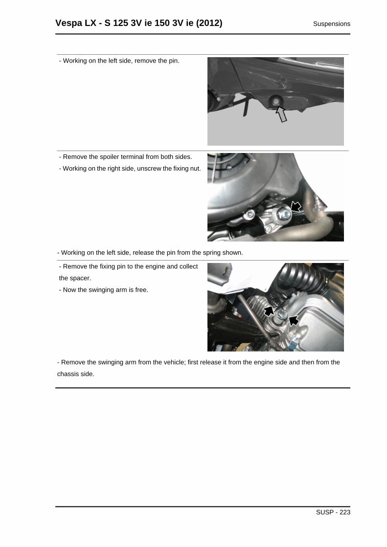
- Working on the left side, remove the pin.
- Remove the spoiler terminal from both sides.
- Working on the right side, unscrew the fixing nut.
- Working on the left side, release the pin from the spring shown.
- Remove the fixing pin to the engine and collect
the spacer.
- Now the swinging arm is free.
- Remove the swinging arm from the vehicle; first release it from the engine side and then from the
chassis side.
Vespa LX - S 125 3V ie 150 3V ie (2012) Suspensions
SUSP - 223
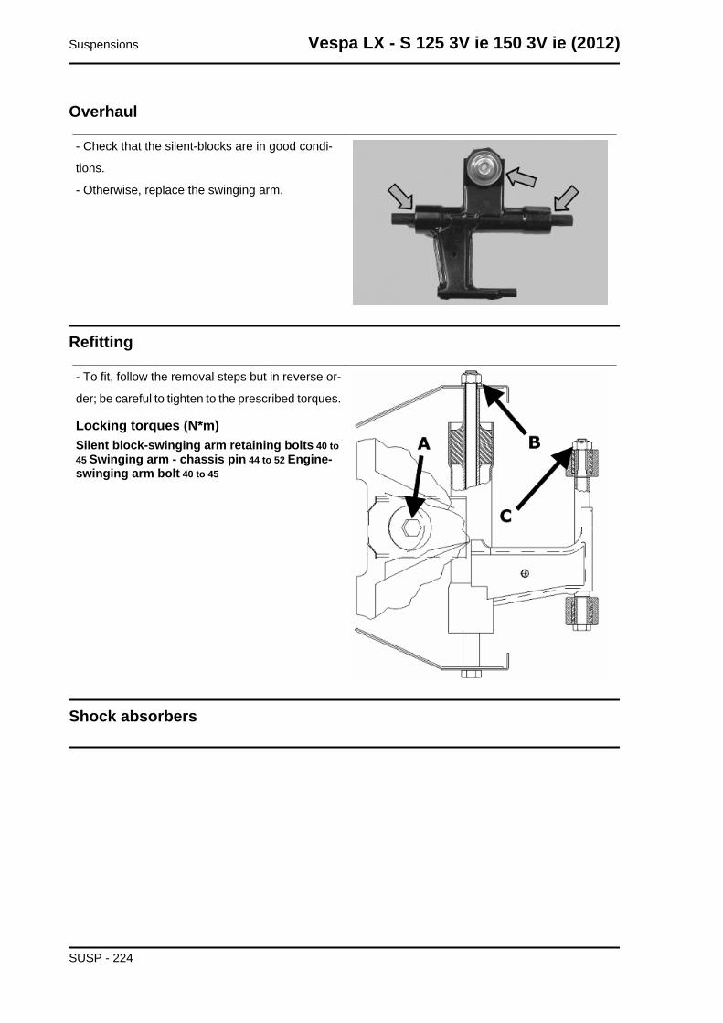
Overhaul
- Check that the silent-blocks are in good condi-
tions.
- Otherwise, replace the swinging arm.
Refitting
- To fit, follow the removal steps but in reverse or-
der; be careful to tighten to the prescribed torques.
Locking torques (N*m)Silent block-swinging arm retaining bolts 40 to45 Swinging arm - chassis pin 44 to 52 Engine-swinging arm bolt 40 to 45
Shock absorbers
Suspensions Vespa LX - S 125 3V ie 150 3V ie (2012)
SUSP - 224
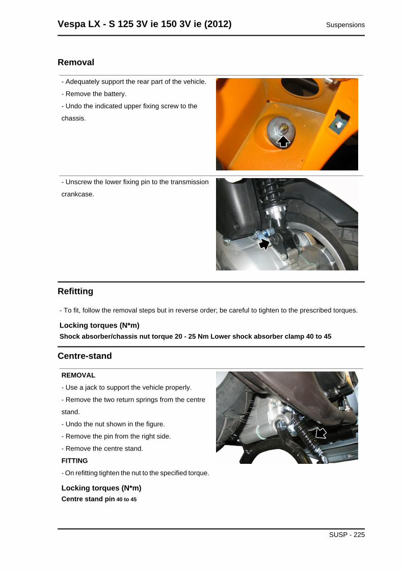
Removal
- Adequately support the rear part of the vehicle.
- Remove the battery.
- Undo the indicated upper fixing screw to the
chassis.
- Unscrew the lower fixing pin to the transmission
crankcase.
Refitting
- To fit, follow the removal steps but in reverse order; be careful to tighten to the prescribed torques.
Locking torques (N*m)Shock absorber/chassis nut torque 20 - 25 Nm Lower shock absorber clamp 40 to 45
Centre-stand
REMOVAL
- Use a jack to support the vehicle properly.
- Remove the two return springs from the centre
stand.
- Undo the nut shown in the figure.
- Remove the pin from the right side.
- Remove the centre stand.
FITTING
- On refitting tighten the nut to the specified torque.
Locking torques (N*m)Centre stand pin 40 to 45
Vespa LX - S 125 3V ie 150 3V ie (2012) Suspensions
SUSP - 225
Suspensions Vespa LX - S 125 3V ie 150 3V ie (2012)
SUSP - 226
INDEX OF TOPICS
BRAKING SYSTEM BRAK SYS
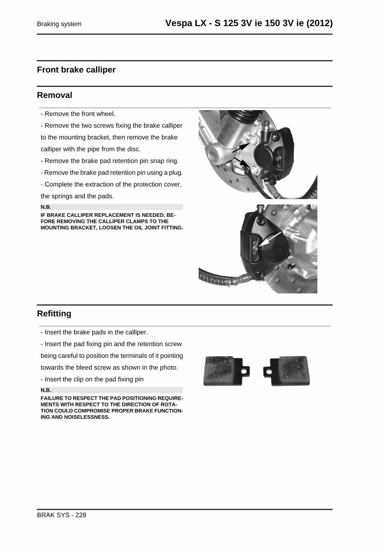
Front brake calliper
Removal
- Remove the front wheel.
- Remove the two screws fixing the brake calliper
to the mounting bracket, then remove the brake
calliper with the pipe from the disc.
- Remove the brake pad retention pin snap ring.
- Remove the brake pad retention pin using a plug.
- Complete the extraction of the protection cover,
the springs and the pads.N.B.IF BRAKE CALLIPER REPLACEMENT IS NEEDED, BE-FORE REMOVING THE CALLIPER CLAMPS TO THEMOUNTING BRACKET, LOOSEN THE OIL JOINT FITTING.
Refitting
- Insert the brake pads in the calliper.
- Insert the pad fixing pin and the retention screw
being careful to position the terminals of it pointing
towards the bleed screw as shown in the photo.
- Insert the clip on the pad fixing pinN.B.FAILURE TO RESPECT THE PAD POSITIONING REQUIRE-MENTS WITH RESPECT TO THE DIRECTION OF ROTA-TION COULD COMPROMISE PROPER BRAKE FUNCTION-ING AND NOISELESSNESS.
Braking system Vespa LX - S 125 3V ie 150 3V ie (2012)
BRAK SYS - 228
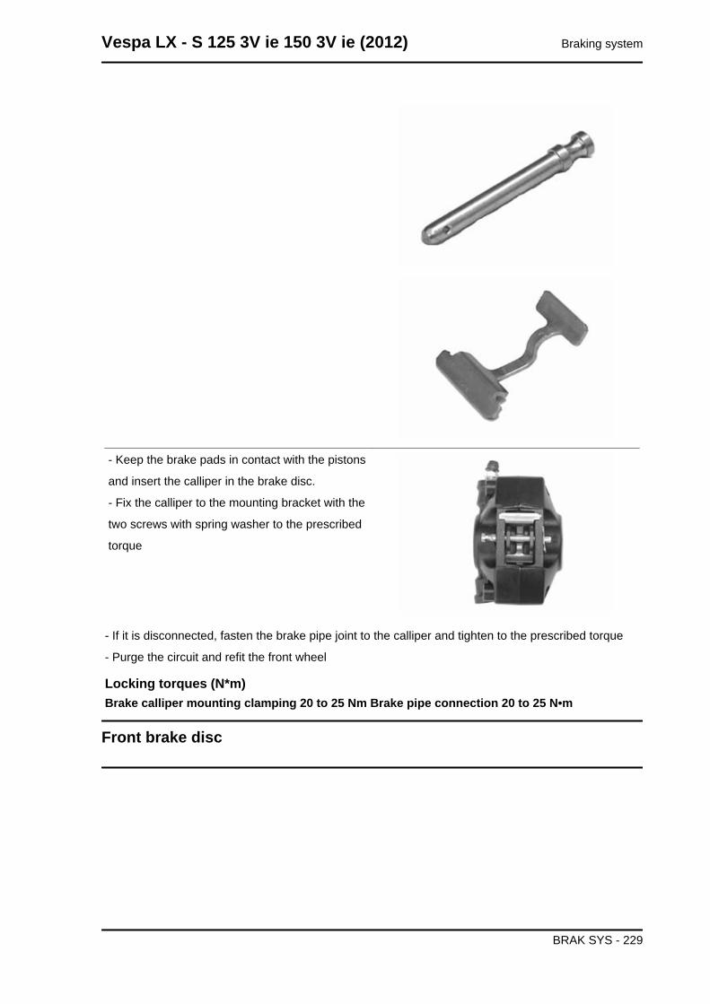
- Keep the brake pads in contact with the pistons
and insert the calliper in the brake disc.
- Fix the calliper to the mounting bracket with the
two screws with spring washer to the prescribed
torque
- If it is disconnected, fasten the brake pipe joint to the calliper and tighten to the prescribed torque
- Purge the circuit and refit the front wheel
Locking torques (N*m)Brake calliper mounting clamping 20 to 25 Nm Brake pipe connection 20 to 25 N•m
Front brake disc
Vespa LX - S 125 3V ie 150 3V ie (2012) Braking system
BRAK SYS - 229
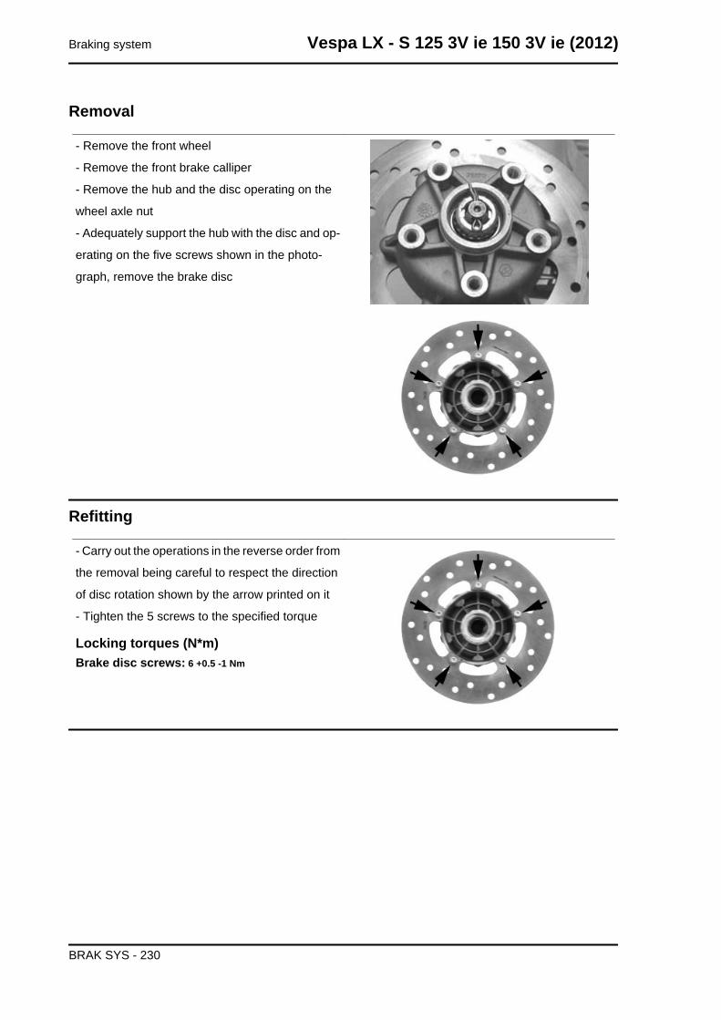
Removal
- Remove the front wheel
- Remove the front brake calliper
- Remove the hub and the disc operating on the
wheel axle nut
- Adequately support the hub with the disc and op-
erating on the five screws shown in the photo-
graph, remove the brake disc
Refitting
- Carry out the operations in the reverse order from
the removal being careful to respect the direction
of disc rotation shown by the arrow printed on it
- Tighten the 5 screws to the specified torque
Locking torques (N*m)Brake disc screws: 6 +0.5 -1 Nm
Braking system Vespa LX - S 125 3V ie 150 3V ie (2012)
BRAK SYS - 230
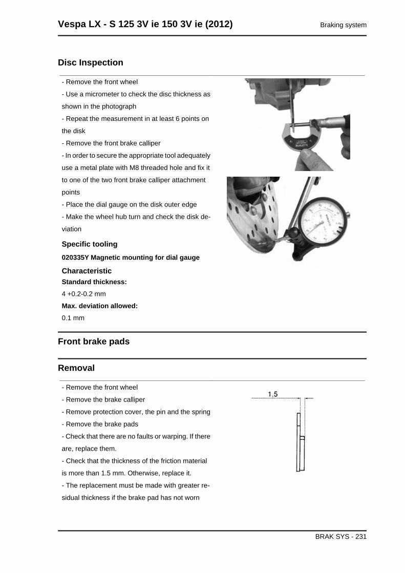
Disc Inspection
- Remove the front wheel
- Use a micrometer to check the disc thickness as
shown in the photograph
- Repeat the measurement in at least 6 points on
the disk
- Remove the front brake calliper
- In order to secure the appropriate tool adequately
use a metal plate with M8 threaded hole and fix it
to one of the two front brake calliper attachment
points
- Place the dial gauge on the disk outer edge
- Make the wheel hub turn and check the disk de-
viation
Specific tooling020335Y Magnetic mounting for dial gauge
CharacteristicStandard thickness:4 +0.2-0.2 mm
Max. deviation allowed:0.1 mm
Front brake pads
Removal
- Remove the front wheel
- Remove the brake calliper
- Remove protection cover, the pin and the spring
- Remove the brake pads
- Check that there are no faults or warping. If there
are, replace them.
- Check that the thickness of the friction material
is more than 1.5 mm. Otherwise, replace it.
- The replacement must be made with greater re-
sidual thickness if the brake pad has not worn
Vespa LX - S 125 3V ie 150 3V ie (2012) Braking system
BRAK SYS - 231
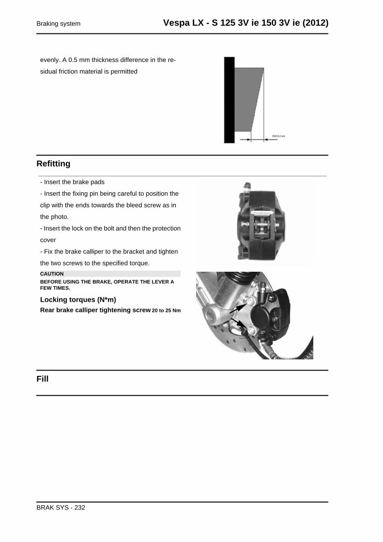
evenly. A 0.5 mm thickness difference in the re-
sidual friction material is permitted
Refitting
- Insert the brake pads
- Insert the fixing pin being careful to position the
clip with the ends towards the bleed screw as in
the photo.
- Insert the lock on the bolt and then the protection
cover
- Fix the brake calliper to the bracket and tighten
the two screws to the specified torque.CAUTIONBEFORE USING THE BRAKE, OPERATE THE LEVER AFEW TIMES.
Locking torques (N*m)Rear brake calliper tightening screw 20 to 25 Nm
Fill
Braking system Vespa LX - S 125 3V ie 150 3V ie (2012)
BRAK SYS - 232
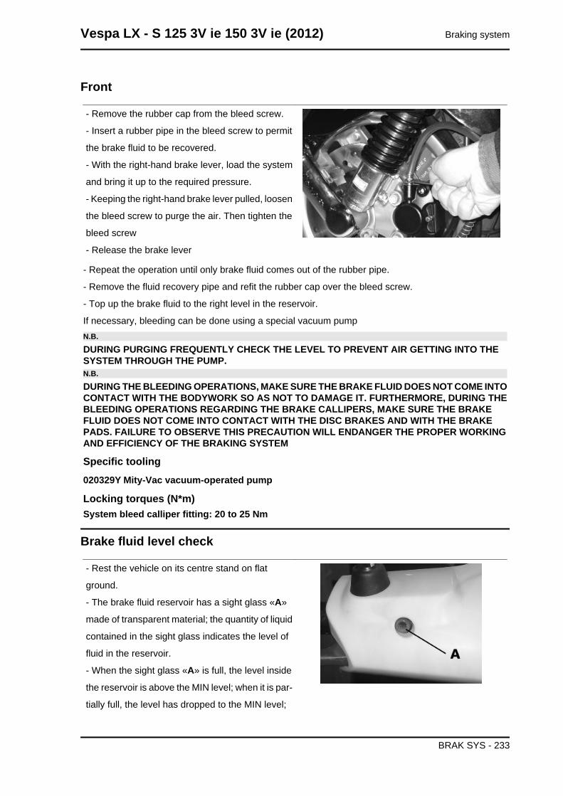
Front
- Remove the rubber cap from the bleed screw.
- Insert a rubber pipe in the bleed screw to permit
the brake fluid to be recovered.
- With the right-hand brake lever, load the system
and bring it up to the required pressure.
- Keeping the right-hand brake lever pulled, loosen
the bleed screw to purge the air. Then tighten the
bleed screw
- Release the brake lever
- Repeat the operation until only brake fluid comes out of the rubber pipe.
- Remove the fluid recovery pipe and refit the rubber cap over the bleed screw.
- Top up the brake fluid to the right level in the reservoir.
If necessary, bleeding can be done using a special vacuum pumpN.B.
DURING PURGING FREQUENTLY CHECK THE LEVEL TO PREVENT AIR GETTING INTO THESYSTEM THROUGH THE PUMP.N.B.
DURING THE BLEEDING OPERATIONS, MAKE SURE THE BRAKE FLUID DOES NOT COME INTOCONTACT WITH THE BODYWORK SO AS NOT TO DAMAGE IT. FURTHERMORE, DURING THEBLEEDING OPERATIONS REGARDING THE BRAKE CALLIPERS, MAKE SURE THE BRAKEFLUID DOES NOT COME INTO CONTACT WITH THE DISC BRAKES AND WITH THE BRAKEPADS. FAILURE TO OBSERVE THIS PRECAUTION WILL ENDANGER THE PROPER WORKINGAND EFFICIENCY OF THE BRAKING SYSTEM
Specific tooling020329Y Mity-Vac vacuum-operated pump
Locking torques (N*m)System bleed calliper fitting: 20 to 25 Nm
Brake fluid level check
- Rest the vehicle on its centre stand on flat
ground.
- The brake fluid reservoir has a sight glass «A»
made of transparent material; the quantity of liquid
contained in the sight glass indicates the level of
fluid in the reservoir.
- When the sight glass «A» is full, the level inside
the reservoir is above the MIN level; when it is par-
tially full, the level has dropped to the MIN level;
Vespa LX - S 125 3V ie 150 3V ie (2012) Braking system
BRAK SYS - 233
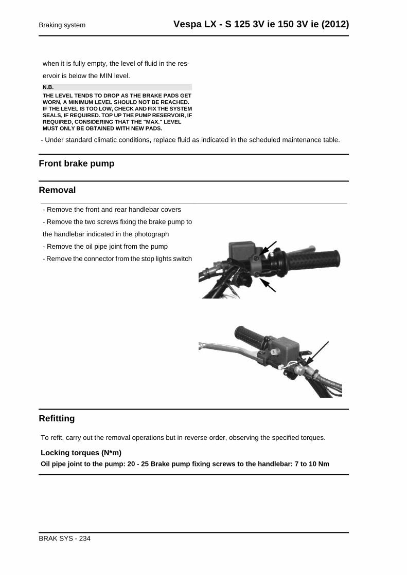
when it is fully empty, the level of fluid in the res-
ervoir is below the MIN level.N.B.THE LEVEL TENDS TO DROP AS THE BRAKE PADS GETWORN, A MINIMUM LEVEL SHOULD NOT BE REACHED.IF THE LEVEL IS TOO LOW, CHECK AND FIX THE SYSTEMSEALS, IF REQUIRED. TOP UP THE PUMP RESERVOIR, IFREQUIRED, CONSIDERING THAT THE "MAX." LEVELMUST ONLY BE OBTAINED WITH NEW PADS.
- Under standard climatic conditions, replace fluid as indicated in the scheduled maintenance table.
Front brake pump
Removal
- Remove the front and rear handlebar covers
- Remove the two screws fixing the brake pump to
the handlebar indicated in the photograph
- Remove the oil pipe joint from the pump
- Remove the connector from the stop lights switch
Refitting
To refit, carry out the removal operations but in reverse order, observing the specified torques.
Locking torques (N*m)Oil pipe joint to the pump: 20 - 25 Brake pump fixing screws to the handlebar: 7 to 10 Nm
Braking system Vespa LX - S 125 3V ie 150 3V ie (2012)
BRAK SYS - 234
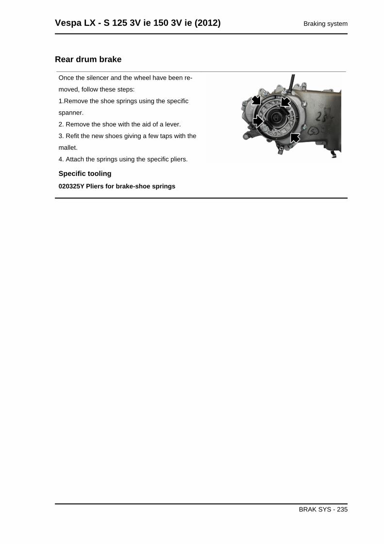
Rear drum brake
Once the silencer and the wheel have been re-
moved, follow these steps:
1.Remove the shoe springs using the specific
spanner.
2. Remove the shoe with the aid of a lever.
3. Refit the new shoes giving a few taps with the
mallet.
4. Attach the springs using the specific pliers.
Specific tooling020325Y Pliers for brake-shoe springs
Vespa LX - S 125 3V ie 150 3V ie (2012) Braking system
BRAK SYS - 235
INDEX OF TOPICS
CHASSIS CHAS
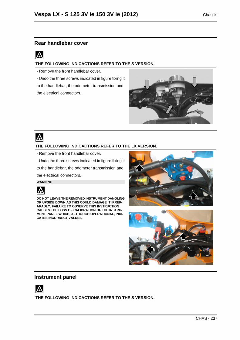
Rear handlebar cover
THE FOLLOWING INDICACTIONS REFER TO THE S VERSION.
- Remove the front handlebar cover.
- Undo the three screws indicated in figure fixing it
to the handlebar, the odometer transmission and
the electrical connectors.
THE FOLLOWING INDICACTIONS REFER TO THE LX VERSION.
- Remove the front handlebar cover.
- Undo the three screws indicated in figure fixing it
to the handlebar, the odometer transmission and
the electrical connectors.WARNING
DO NOT LEAVE THE REMOVED INSTRUMENT DANGLINGOR UPSIDE DOWN AS THIS COULD DAMAGE IT IRREP-ARABLY. FAILURE TO OBSERVE THIS INSTRUCTIONCAUSES THE LOSS OF CALIBRATION OF THE INSTRU-MENT PANEL WHICH, ALTHOUGH OPERATIONAL, INDI-CATES INCORRECT VALUES.
Instrument panel
THE FOLLOWING INDICACTIONS REFER TO THE S VERSION.
Vespa LX - S 125 3V ie 150 3V ie (2012) Chassis
CHAS - 237
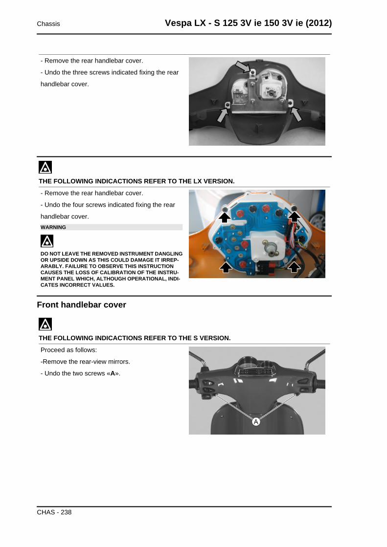
- Remove the rear handlebar cover.
- Undo the three screws indicated fixing the rear
handlebar cover.
THE FOLLOWING INDICACTIONS REFER TO THE LX VERSION.
- Remove the rear handlebar cover.
- Undo the four screws indicated fixing the rear
handlebar cover.WARNING
DO NOT LEAVE THE REMOVED INSTRUMENT DANGLINGOR UPSIDE DOWN AS THIS COULD DAMAGE IT IRREP-ARABLY. FAILURE TO OBSERVE THIS INSTRUCTIONCAUSES THE LOSS OF CALIBRATION OF THE INSTRU-MENT PANEL WHICH, ALTHOUGH OPERATIONAL, INDI-CATES INCORRECT VALUES.
Front handlebar cover
THE FOLLOWING INDICACTIONS REFER TO THE S VERSION.
Proceed as follows:
-Remove the rear-view mirrors.
- Undo the two screws «A».
Chassis Vespa LX - S 125 3V ie 150 3V ie (2012)
CHAS - 238
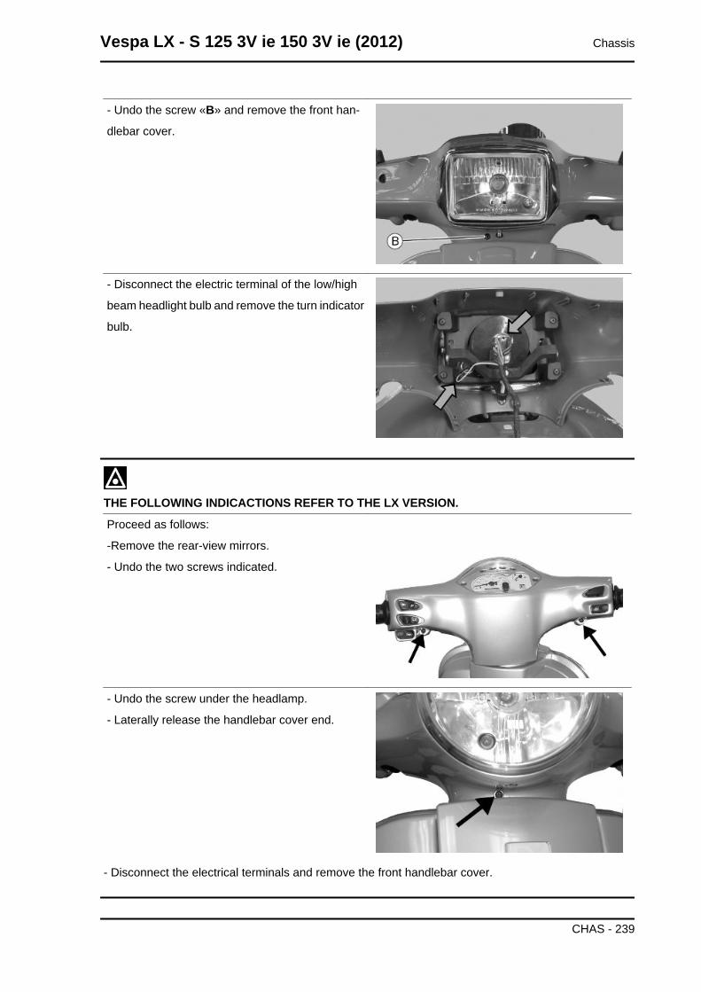
- Undo the screw «B» and remove the front han-
dlebar cover.
- Disconnect the electric terminal of the low/high
beam headlight bulb and remove the turn indicator
bulb.
THE FOLLOWING INDICACTIONS REFER TO THE LX VERSION.
Proceed as follows:
-Remove the rear-view mirrors.
- Undo the two screws indicated.
- Undo the screw under the headlamp.
- Laterally release the handlebar cover end.
- Disconnect the electrical terminals and remove the front handlebar cover.
Vespa LX - S 125 3V ie 150 3V ie (2012) Chassis
CHAS - 239
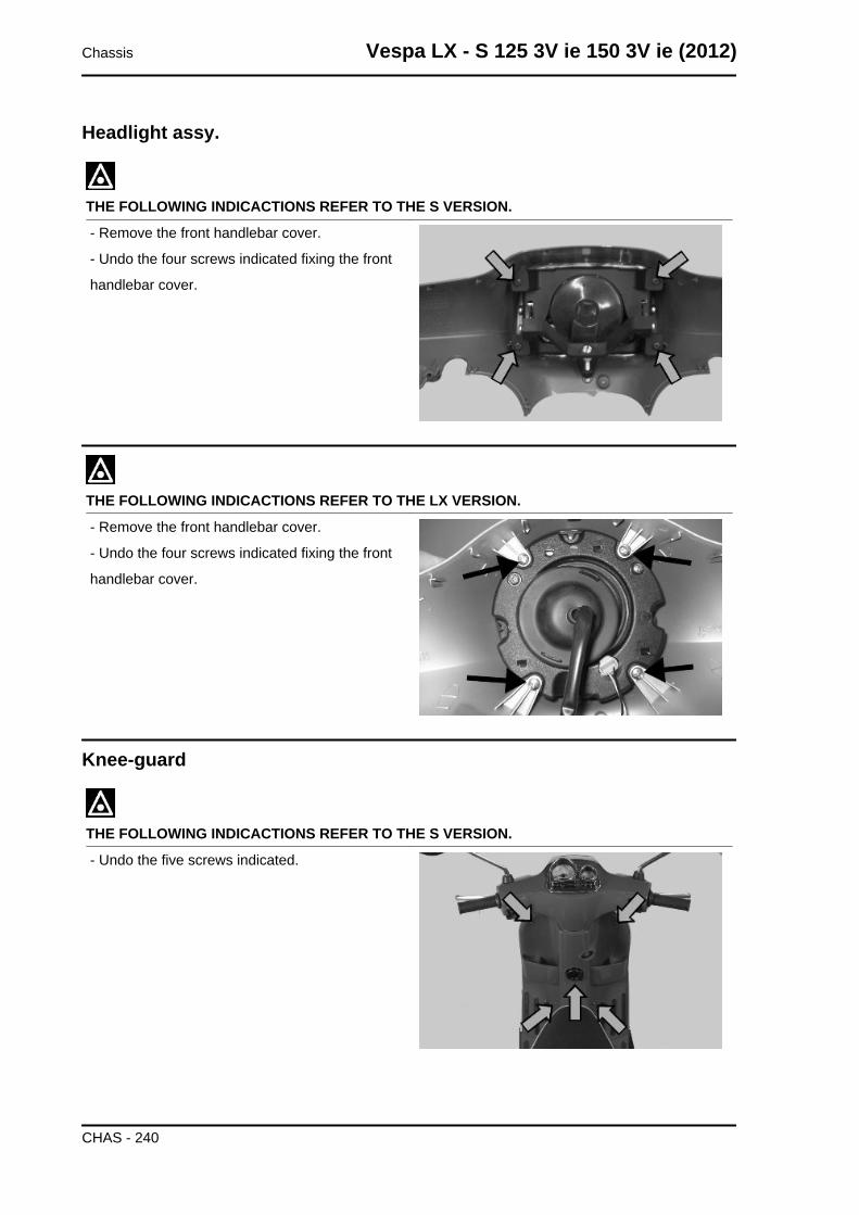
Headlight assy.
THE FOLLOWING INDICACTIONS REFER TO THE S VERSION.
- Remove the front handlebar cover.
- Undo the four screws indicated fixing the front
handlebar cover.
THE FOLLOWING INDICACTIONS REFER TO THE LX VERSION.
- Remove the front handlebar cover.
- Undo the four screws indicated fixing the front
handlebar cover.
Knee-guard
THE FOLLOWING INDICACTIONS REFER TO THE S VERSION.
- Undo the five screws indicated.
Chassis Vespa LX - S 125 3V ie 150 3V ie (2012)
CHAS - 240
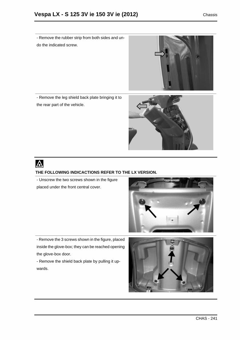
- Remove the rubber strip from both sides and un-
do the indicated screw.
- Remove the leg shield back plate bringing it to
the rear part of the vehicle.
THE FOLLOWING INDICACTIONS REFER TO THE LX VERSION.
- Unscrew the two screws shown in the figure
placed under the front central cover.
- Remove the 3 screws shown in the figure, placed
inside the glove-box; they can be reached opening
the glove-box door.
- Remove the shield back plate by pulling it up-
wards.
Vespa LX - S 125 3V ie 150 3V ie (2012) Chassis
CHAS - 241
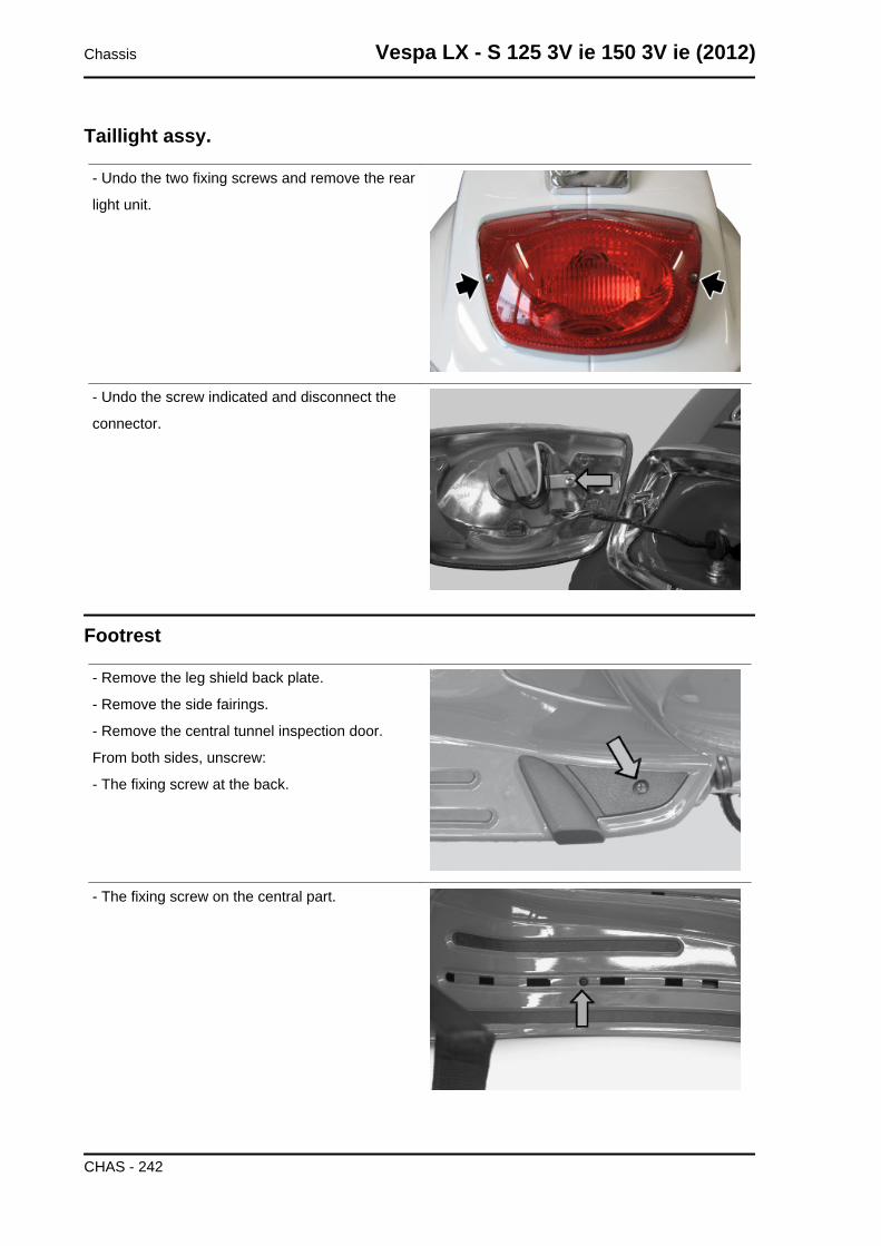
Taillight assy.
- Undo the two fixing screws and remove the rear
light unit.
- Undo the screw indicated and disconnect the
connector.
Footrest
- Remove the leg shield back plate.
- Remove the side fairings.
- Remove the central tunnel inspection door.
From both sides, unscrew:
- The fixing screw at the back.
- The fixing screw on the central part.
Chassis Vespa LX - S 125 3V ie 150 3V ie (2012)
CHAS - 242
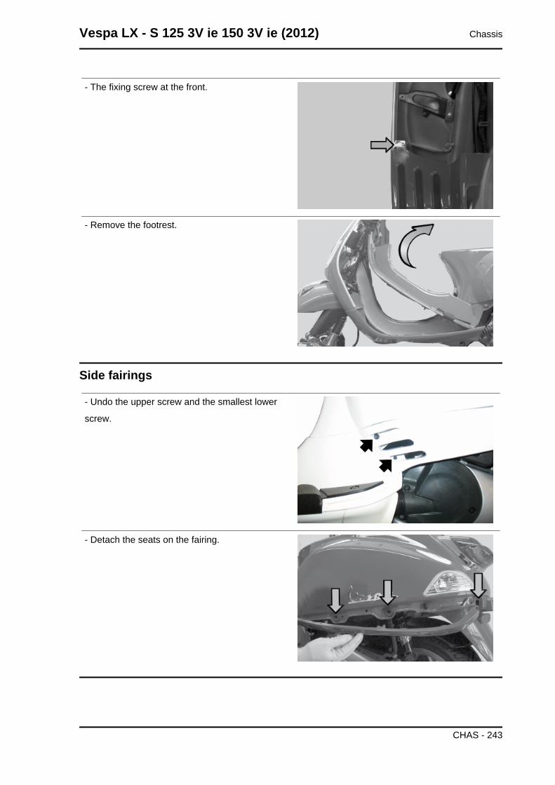
- The fixing screw at the front.
- Remove the footrest.
Side fairings
- Undo the upper screw and the smallest lower
screw.
- Detach the seats on the fairing.
Vespa LX - S 125 3V ie 150 3V ie (2012) Chassis
CHAS - 243
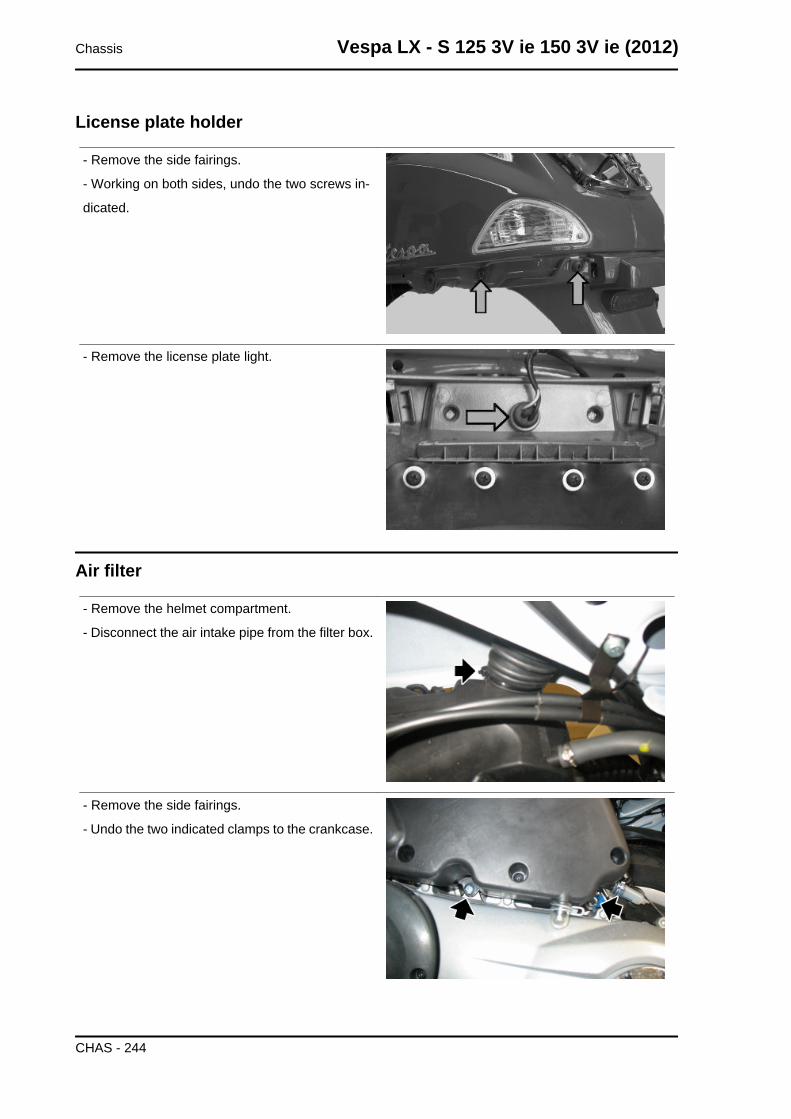
License plate holder
- Remove the side fairings.
- Working on both sides, undo the two screws in-
dicated.
- Remove the license plate light.
Air filter
- Remove the helmet compartment.
- Disconnect the air intake pipe from the filter box.
- Remove the side fairings.
- Undo the two indicated clamps to the crankcase.
Chassis Vespa LX - S 125 3V ie 150 3V ie (2012)
CHAS - 244
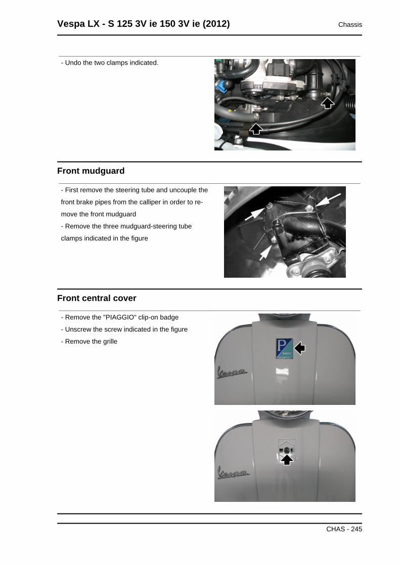
- Undo the two clamps indicated.
Front mudguard
- First remove the steering tube and uncouple the
front brake pipes from the calliper in order to re-
move the front mudguard
- Remove the three mudguard-steering tube
clamps indicated in the figure
Front central cover
- Remove the "PIAGGIO" clip-on badge
- Unscrew the screw indicated in the figure
- Remove the grille
Vespa LX - S 125 3V ie 150 3V ie (2012) Chassis
CHAS - 245
INDEX OF TOPICS
PRE-DELIVERY PRE DE
Aesthetic inspection
Appearance check:
- Paintwork
- Fitting of plastics
- Scratches
- Dirt
Tightening torques inspection
Lock check
- Safety fasteners
- Fixing screws
Safety fasteners:
• Rear shock absorber upper retainer
• Rear shock absorber lower clamping
• Front wheel axle nut
• Front wheel screws
• Wheel hub nut
• Front brake calliper fixing screws
• Swinging arm - chassis pin
• Engine-swinging arm pin
• Engine arm pin - Chassis arm
• Handlebar lock nut
• Lower steering ring nut
• Upper steering ring nut
Electrical system
Electrical system:
- Battery
- Main switch
- Headlamps: high beam lights, low beam lights, tail lights and their warning lights
- Adjusting the headlights according to the regulations currently in force
- Rear light, brake light and license plate light
- Front and rear stop light switches
- Turn indicators and their warning lights
- Instrument panel lights
- Instrument panel: fuel gauge
Vespa LX - S 125 3V ie 150 3V ie (2012) Pre-delivery
PRE DE - 247
- Instrument panel warning lights
- Horn
- StarterCAUTION
TO ENSURE MAXIMUM PERFORMANCE, THE BATTERY MUST BE CHARGED BEFORE USE.INADEQUATE CHARGING OF THE BATTERY WITH A LOW LEVEL OF ELECTROLYTE BEFOREIT IS FIRST USED SHORTENS THE LIFE OF THE BATTERY.WARNING
KEEP SPARKS AND NAKED FLAMES AWAY FROM THE BATTERY WHILE RECHARGING. RE-MOVE THE BATTERY FROM THE VEHICLE, DISCONNECTING THE NEGATIVE TERMINALFIRST.CAUTION
WHEN INSTALLING THE BATTERY, ATTACH THE POSITIVE LEAD FIRST AND THEN THE NEG-ATIVE ONE.WARNING
BATTERY ELECTROLYTE IS TOXIC AND IT MAY CAUSE SERIOUS BURNS. IT CONTAINS SUL-PHURIC ACID. AVOID CONTACT WITH YOUR EYES, SKIN AND CLOTHING.IN CASE OF CONTACT WITH YOUR EYES OR SKIN, RINSE WITH ABUNDANT WATER FORABOUT 15 MINUTES AND SEEK IMMEDIATE MEDICAL ATTENTION.IF IT ACCIDENTALLY SWALLOWED, IMMEDIATELY DRINK LARGE QUANTITIES OF WATER ORVEGETABLE OIL. SEEK IMMEDIATE MEDICAL ATTENTION.BATTERIES PRODUCE EXPLOSIVE GASES; KEEP THEM AWAY FROM NAKED FLAMES,SPARKS AND CIGARETTES. IF THE BATTERY IS CHARGED IN A CLOSED PLACE, TAKE CARETO ENSURE ADEQUATE VENTILATION. ALWAYS PROTECT YOUR EYES WHEN WORKINGCLOSE TO BATTERIES.KEEP OUT OF THE REACH OF CHILDRENCAUTION
NEVER USE FUSES WITH A CAPACITY HIGHER THAN THE RECOMMENDED CAPACITY. USINGA FUSE OF UNSUITABLE RATING MAY SERIOUSLY DAMAGE THE VEHICLE OR EVEN CAUSEA FIRE.
Levels check
Level check:
- Hydraulic braking system fluid level.
- Rear hub oil level
- Engine oil level
Road test
Test ride
- Cold start
- Instrument operations
- Response to the throttle control
- Stability on acceleration and braking
- Rear and front brake efficiency
- Rear and front suspension efficiency
Pre-delivery Vespa LX - S 125 3V ie 150 3V ie (2012)
PRE DE - 248
- Abnormal noise
Static test
Static control after the test ride:
- Restarting when warmed up
- Minimum hold (turning the handlebar)
- Uniform turning of the steering
- Possible leaksCAUTION
CHECK AND ADJUST TYRE PRESSURE WITH TYRES AT AMBIENT TEMPERATURE.CAUTION
NEVER EXCEED THE RECOMMENDED INFLATION PRESSURES OR TYRES MAY BURST.
Functional inspection
Functional Checks:
Braking system (hydraulic)
- Lever travel
Braking system (mechanical)
- Lever travel
Clutch
- Proper functioning check
Engine
- Proper general functioning and no abnormal noise check
Others
- Check documentation
- Check the chassis and engine numbers
- Tool kit
- License plate fitting
- Check locks
- Check tyre pressures
- Installation of mirrors and any accessories
Vespa LX - S 125 3V ie 150 3V ie (2012) Pre-delivery
PRE DE - 249
AAir filter: 41, 244
BBattery: 51, 70, 83, 93, 94Brake: 228, 229, 231, 233–235Brake fluid: 233Bulbs:
CChecks: 78
EEngine oil: 42
FFuel: 186, 194Fuses: 91
HHeadlight: 47, 240Horn: 86Hub oil: 40
IIdentification: 8Instrument panel: 237
MMaintenance: 7, 38
OOil filter: 44
RRecommended products:
SShock absorbers: 224Spark plug: 38Suspension: 51
TTransmission: 10, 50, 115, 127Turn indicators: 74
Tyres: 11
VVehicle: 8, 110