Service Manual Trucks - Heavy Haulers RV Resource Guide Documents... · Service Manual Trucks Group...
150
Service Manual Trucks Group 300–500 Electrical General VN from 2/98 and VHD PV776-20 007111
Transcript of Service Manual Trucks - Heavy Haulers RV Resource Guide Documents... · Service Manual Trucks Group...
Service ManualTrucks
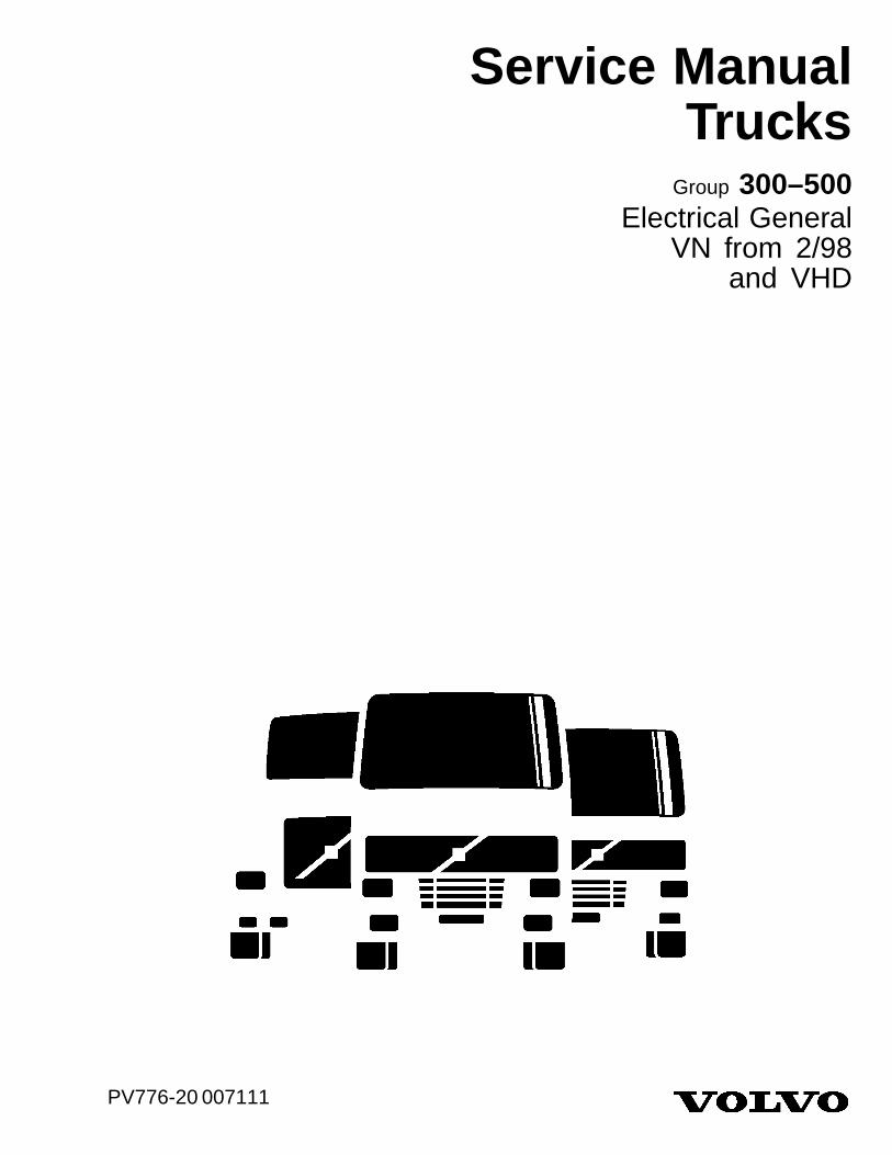
Group 300–500Electrical General
VN from 2/98and VHD
PV776-20 007111

Foreword
The descriptions and service procedures contained in this manual are based on designsand methods studies carried out up to April 2004.
The products are under continuous development. Vehicles and components producedafter the above date may therefore have different specifications and repair methods.When this is believed to have a significant bearing on this manual, supplementaryservice bulletins will be issued to cover the changes.
The new edition of this manual will update the changes.
In service procedures where the title incorporates an operation number, this is areference to an V.S.T. (Volvo Standard Times).
Service procedures which do not include an operation number in the title are for generalinformation and no reference is made to an V.S.T.
Each section of this manual contains specific safety information and warnings whichmust be reviewed before performing any procedure. If a printed copy of a procedure ismade, be sure to also make a printed copy of the safety information and warnings thatrelate to that procedure. The following levels of observations, cautions and warningsare used in this Service Documentation:
Note: Indicates a situation, handling or circumstance which should be observed.
Caution: Indicates a potentially hazardous situation which, if not avoided, may result inminor or moderate injury or damage to property.
Warning: Indicates a potentially hazardous situation which, if not avoided, could resultin death, serious injury or major damage to property.
Danger: Indicates an imminently hazardous situation which, if not avoided, will result indeath or serious injury.
Volvo Trucks North America, Inc.Greensboro, NC USA
Order number: PV776-20 007111Repl: This Service Manual replaces Service Manual, “Electrical General, VN from 2/98 and VHD” (08.2000), publication
number PV776–TSP145645.
© 2004 Volvo Trucks North America, Inc., Greensboro, NC USA
All rights reserved. No part of this publication may be reproduced, stored inretrieval system, or transmitted in any forms by any means, electronic,mechanical, photocopying, recording or otherwise, without the prior writtenpermission of Volvo Trucks North America, Inc..
USA15172


ContentsGeneral .................................................................................................... 5General Information ................................................................................. 5
Tools ........................................................................................................ 7Special Tools .......................................................................................... 7Special Equipment ................................................................................. 8
Design and Function ............................................................................. 9Electrical General .................................................................................... 9
............................................................................................................... 10Typical Circuit Components ................................................................. 10Data Link Communication .................................................................... 13Starting and Charging System ............................................................. 17Fuse and Relay Locations ................................................................... 32Switches and Controls ......................................................................... 36Instrumentation .................................................................................... 52Lighting System ................................................................................... 53Supplemental Restraint System .......................................................... 54Vehicle ECU ......................................................................................... 55Central Door Lock Module ................................................................... 56Smoke Detector ................................................................................... 57Horn ..................................................................................................... 59TV Antenna and Speaker .................................................................... 61Bodybuilder Wiring ............................................................................... 63
Troubleshooting ................................................................................... 67Electrical System Troubleshooting ......................................................... 67Electrical System ................................................................................... 67
Troubleshooting Using a Digital Multimeter ......................................... 67Troubleshooting Wiring and Connectors .............................................. 68
Service Procedures ............................................................................. 79Engine ECU Terminal, Replacement ................................................... 79JAE Terminal, Replacement ................................................................ 81Mini-fuse, Replacement ....................................................................... 83Relay, Replacement ............................................................................. 84Fusible Link, Replacement (Battery Side) ........................................... 84Fusible Link, Replacement (Ground Cable) ......................................... 88Central Door Lock Module, Replacement ............................................ 91Central Door Lock Module, Replacement ............................................ 93Ignition Switch, Replacement .............................................................. 95Ignition Switch and Housing, Replacement ......................................... 98Air Horn Contact, Replacement ........................................................ 102City Horn Contact, Replacement ....................................................... 107City Horn, Replacement .................................................................... 109Air Horn Solenoid, Replacement ....................................................... 110Turn Signal/CC Switch Assembly, Replacement ................................ 111Hazard Warning Switch, Replacement .............................................. 114Back of Cab Lamp Switch, Replacement .......................................... 114Fan Switch, Replacement .................................................................. 114PTO Switch, Replacement ................................................................. 114Bunk Overhead Lamp Switch, Replacement ..................................... 114Headlamp Interrupt Switch, Replacement ......................................... 114Snowplow Lamp Switch, Replacement .............................................. 114Smoke Detector Disable Switch, Replacement ................................. 114Switch, Replacement (Left Dash Switches) ....................................... 115
1

Sleeper Control Panel Switch, Replacement ..................................... 118Auxiliary Switch, Replacement .......................................................... 118Marker Interrupt Switch, Replacement .............................................. 118Engine/Exhaust Brake Switch, Replacement .................................... 118Traction Control Switch, Replacement ............................................... 118Heated Mirror Switch, Replacement .................................................. 118Lift Axle Switch, Replacement ........................................................... 118Beacon Lamp Switch, Replacement .................................................. 118Right Dash/Auxiliary/Sleeper Control Panel Switch, Replacement .... 119Pneumatic Switch, Replacement ....................................................... 121Headlamp/Parking Lamp Switch, Replacement ................................ 123Fog/Driving Lamp Switch, Replacement ............................................ 126Dash Dimmer Control Switch, Replacement ..................................... 129Cigar Lighter, Replacement ............................................................... 132Window/Power Mirror Switch, Replacement ...................................... 134Digital Clock, Replacement (Sleeper) ................................................ 137TV Speaker/Headphone Jack, Replacement ..................................... 139Smoke Detector/Battery, Replacement .............................................. 141
Operation Numbers
2

3

4
Group 3 Electrical System, VN & VHD General
General
General Information
W8002831
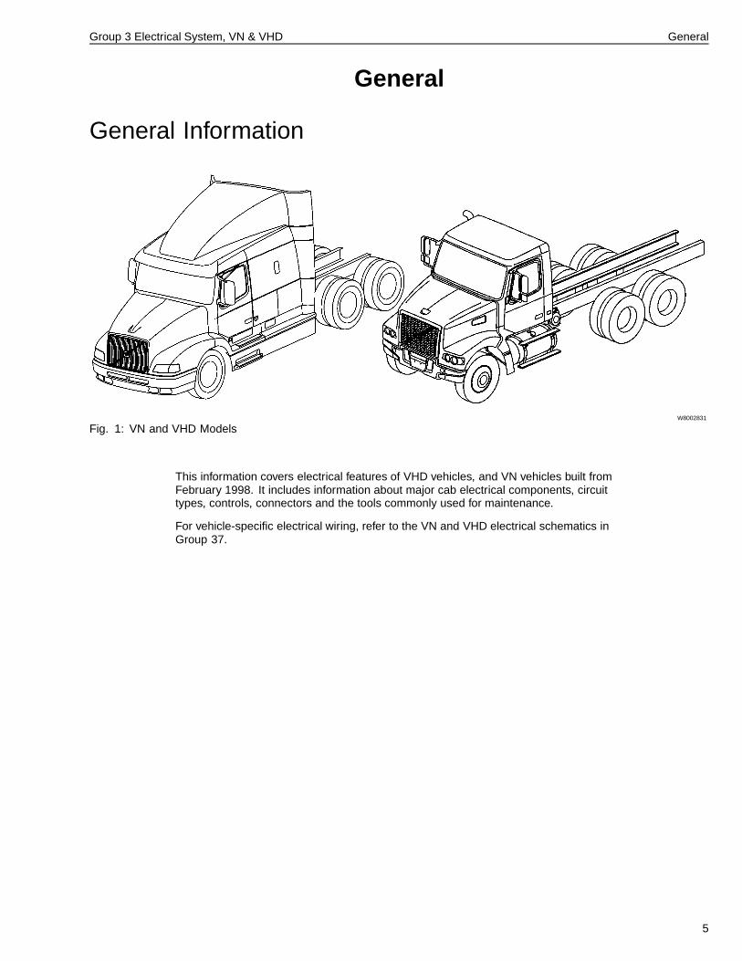
Fig. 1: VN and VHD Models
This information covers electrical features of VHD vehicles, and VN vehicles built fromFebruary 1998. It includes information about major cab electrical components, circuittypes, controls, connectors and the tools commonly used for maintenance.
For vehicle-specific electrical wiring, refer to the VN and VHD electrical schematics inGroup 37.
5

6
Group 3 Electrical System, VN & VHD Tools
Tools
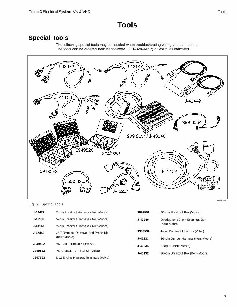
Special ToolsThe following special tools may be needed when troubleshooting wiring and connectors.The tools can be ordered from Kent-Moore (800–328–6657) or Volvo, as indicated.
W0001767
Fig. 2: Special Tools
J-42472 2–pin Breakout Harness (Kent-Moore)
J-41133 5–pin Breakout Harness (Kent-Moore)
J-43147 2–pin Breakout Harness (Kent-Moore)
J-42449 JAE Terminal Removal and Probe Kit(Kent-Moore)
3949522 VN Cab Terminal Kit (Volvo)
3949523 VN Chassis Terminal Kit (Volvo)
3947553 D12 Engine Harness Terminals (Volvo)
9998551 60–pin Breakout Box (Volvo)
J-43340 Overlay for 60–pin Breakout Box(Kent-Moore)
9998534 4–pin Breakout Harness (Volvo)
J-43233 36–pin Jumper Harness (Kent-Moore)
J-43234 Adapter (Kent-Moore)
J-41132 36–pin Breakout Box (Kent-Moore)
7
Group 3 Electrical System, VN & VHD Tools
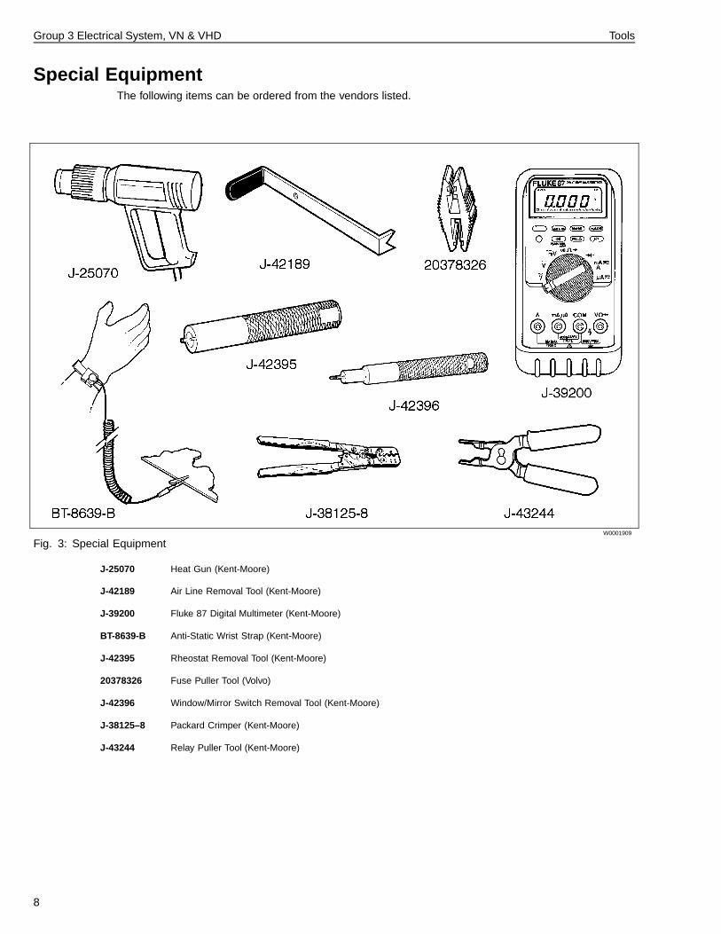
Special EquipmentThe following items can be ordered from the vendors listed.
W0001909
Fig. 3: Special Equipment
J-25070 Heat Gun (Kent-Moore)
J-42189 Air Line Removal Tool (Kent-Moore)
J-39200 Fluke 87 Digital Multimeter (Kent-Moore)
BT-8639-B Anti-Static Wrist Strap (Kent-Moore)
J-42395 Rheostat Removal Tool (Kent-Moore)
20378326 Fuse Puller Tool (Volvo)
J-42396 Window/Mirror Switch Removal Tool (Kent-Moore)
J-38125–8 Packard Crimper (Kent-Moore)
J-43244 Relay Puller Tool (Kent-Moore)
8
Group 3 Electrical System, VN & VHD Design and Function
Design and Function
Electrical General• “Typical Circuit Components” page 10
• “Data Link Communication” page 13
• “Starting and Charging System” page 17
• “Fuse and Relay Locations” page 32
• “Switches and Controls” page 36
• “Instrumentation” page 52
• “Lighting System” page 53
• “Supplemental Restraint System” page 54
• “Vehicle ECU” page 55
• “Central Door Lock Module” page 56
• “Smoke Detector” page 57
• “Horn” page 59
• “Bodybuilder Wiring” page 63
9
Group 3 Electrical System, VN & VHD Design and Function
Typical Circuit ComponentsWiring Harnesses, Wires & ConnectorsEach circuit uses a wire of a specific size, based on thecurrent demands for that circuit. The circuit number isstamped into the insulation every 76 mm (3 in.). This aidsin proper connections and simplifies circuit tracing.
Black, numbered wires are fused, powered circuits. Whitewires are ground. Red wires are “hot” at all times andprotected by fusible links. Multi-colored wire harnessesmay be used as interfaces to some components;the definition of those multi-colored wires varies bycomponent.
Some wires are grouped together and encased in asplit plastic casing or braided tubing called a conduit.This grouping of wires is called a harness. Majorwiring harnesses are joined by using multiple plug andreceptacle connectors.
Each harness or wire must be held securely in place byclips or other holding devices to prevent chafing of theinsulation.
Terminals used throughout the system are Deutsch, Amp,JAE, KOSTAL and Packard.
Wiring SchematicsThe wiring schematics for VN/VHD series vehicles arefound in “VN or VHD Series Electrical Schematics,Group 37.” These schematics are continuously updatedto provide detailed, vehicle-specific wiring information.Detailed instructions for schematic use is included inthese binders. The schematics feature:
• Single circuit format• Illustrated location of connectors on the vehicle• Connector cavity, circuit and function details• Fuse numbers• Wire numbers• Splice details• Vehicle variant details
Simplified schematics are sometimes used in manualsand bulletins to help explain component design andfunction features or to clarify troubleshooting instructions.These simplified schematics do not offer the level of detailneeded for vehicle troubleshooting, nor are they updatedregularly. Always use the schematics found in “VN/VHDSeries Electrical Schematics, Group 37” for the mostcurrent information.
Circuit ProtectionTo protect wiring and equipment from overloads, circuitprotectors, such as fuses, are used. Circuit breakers andfusible links are also used.
CAUTION
Failure to use proper circuit protection devices in thevehicle can result in damage to the vehicle and itscomponents. Replace blown fuses only with fuses ofthe same rating. Replace fusible links only with properreplacement parts of the exact gauge and length.Failure to use proper circuit protection could overloadthe circuit, causing severe damage to the vehicle.
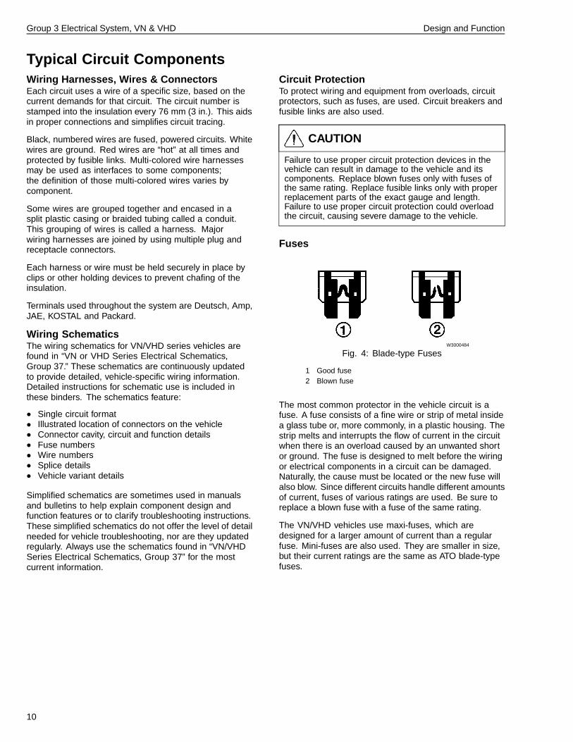
Fuses
W3000484
Fig. 4: Blade-type Fuses
1 Good fuse2 Blown fuse
The most common protector in the vehicle circuit is afuse. A fuse consists of a fine wire or strip of metal insidea glass tube or, more commonly, in a plastic housing. Thestrip melts and interrupts the flow of current in the circuitwhen there is an overload caused by an unwanted shortor ground. The fuse is designed to melt before the wiringor electrical components in a circuit can be damaged.Naturally, the cause must be located or the new fuse willalso blow. Since different circuits handle different amountsof current, fuses of various ratings are used. Be sure toreplace a blown fuse with a fuse of the same rating.
The VN/VHD vehicles use maxi-fuses, which aredesigned for a larger amount of current than a regularfuse. Mini-fuses are also used. They are smaller in size,but their current ratings are the same as ATO blade-typefuses.
10
Group 3 Electrical System, VN & VHD Design and Function
Fusible LinksFusible links are used to protect high-current circuitsagainst current overload when there is a short to ground.The fusible link is a short length of wire that is smallerin gauge than the wire in the protected circuit. In theevent of an overload the fusible link will melt, breaking thecircuit and preventing damage to the electrical system. Ifa fusible link does open, special attention must be paid tofinding and repairing the cause.
Fusible links are used in two locations: two are at thestarter motor on the positive side feeding the cab mainpower studs, and one is from ground on the starter motorto engine ground. The fusible links on the positive sideare 10 gauge cables 120 mm (4.72 in.) in length. On theground side, it is an 8 gauge cable.
DiodesDiodes are used on many of the vehicle’s circuits toprotect and isolate them from voltage surges, which canoccur when a circuit is turned off. Diodes allow voltage toflow in one direction only, like a one-way check valve.
Circuit BreakersCircuit breakers are optional equipment. SAE Type 2modified reset circuit breakers are the only type of circuitbreakers approved for use in VN/VHD vehicles. Theymay be used on accessory and ignition circuits only.Circuit breakers protect a circuit from overload. When anoverload (high current flow) occurs in a circuit, a bimetallicstrip in the breaker is heated. This opens its contact,temporarily breaking the circuit. When this bimetallic stripcools down, it remakes the contact.
Type 2 circuit breakers are opened by current overloadand remain open as long as the power is on. A Type2 circuit breaker keeps the bimetallic strip hot aftertripping by diverting a small amount of current througha small coil of resistance wire. If power to the circuitbreaker is switched off long enough for the bimetallicstrip and resistance wire to cool down, the breaker willautomatically reset.
When any circuit breaker trips, it should be viewed as anindication of a possible fault in the circuit. Every effortshould be made to identify and correct the fault if oneexists.
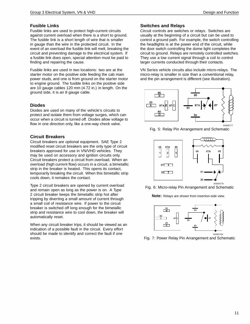
Switches and RelaysCircuit controls are switches or relays. Switches areusually at the beginning of a circuit but can be used tocontrol a ground path. For example, the switch controllingthe headlights is at the power end of the circuit, whilethe door switch controlling the dome light completes thecircuit to ground. Relays are remotely controlled switches.They use a low current signal through a coil to controllarger currents conducted through their contacts.
VN Series vehicle circuits also include micro-relays. Themicro-relay is smaller in size than a conventional relay,and the pin arrangement is different (see illustration).
W3000777
Fig. 5: Relay Pin Arrangement and Schematic
W3000778
Fig. 6: Micro-relay Pin Arrangement and Schematic
Note: Relays are shown from insertion-side view.
W3002794
Fig. 7: Power Relay Pin Arrangement and Schematic
11
Group 3 Electrical System, VN & VHD Design and Function
Sensors and SendersMany electronic signals used by ECUs and the instrumentcluster are supplied by sensors and senders. A sensoror sender sends a signal to a control unit, or to themicroprocessor in the instrument cluster. Sensors usedin the vehicle system include the vehicle speed sensor,the throttle position sensor and Anti-lock Brake System(ABS) wheel speed sensors.
The vehicle speed sensor is mounted in the transmissionand reads the movement of the teeth on the outputshaft. It is of an inductive type and sends a fluctuating(sinusoidal) signal to the engine ECU.
The fuel sender, mounted in the fuel tank, transmits thefuel level to the instrument cluster.
W5000602
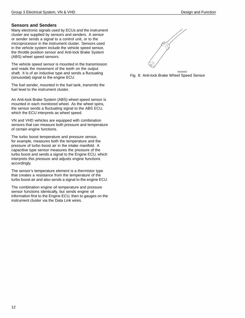
Fig. 8: Anti-lock Brake Wheel Speed Sensor
An Anti-lock Brake System (ABS) wheel speed sensor ismounted in each monitored wheel. As the wheel spins,the sensor sends a fluctuating signal to the ABS ECU,which the ECU interprets as wheel speed.
VN and VHD vehicles are equipped with combinationsensors that can measure both pressure and temperatureof certain engine functions.
The turbo boost temperature and pressure sensor,for example, measures both the temperature and thepressure of turbo boost air in the intake manifold. Acapacitive type sensor measures the pressure of theturbo boost and sends a signal to the Engine ECU, whichinterprets this pressure and adjusts engine functionsaccordingly.
The sensor’s temperature element is a thermistor typethat creates a resistance from the temperature of theturbo boost air and also sends a signal to the engine ECU.
The combination engine oil temperature and pressuresensor functions identically, but sends engine oilinformation first to the Engine ECU, then to gauges on theinstrument cluster via the Data Link wires.
12
Group 3 Electrical System, VN & VHD Design and Function
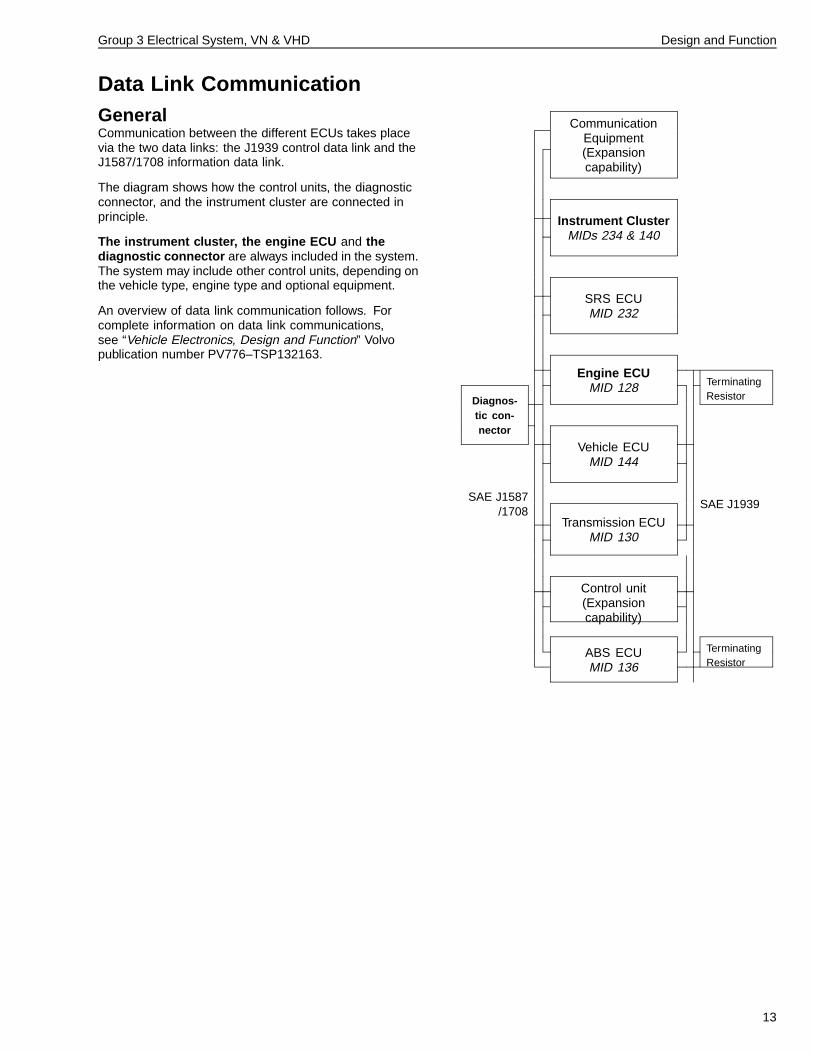
Data Link CommunicationGeneralCommunication between the different ECUs takes placevia the two data links: the J1939 control data link and theJ1587/1708 information data link.
The diagram shows how the control units, the diagnosticconnector, and the instrument cluster are connected inprinciple.
The instrument cluster, the engine ECU and thediagnostic connector are always included in the system.The system may include other control units, depending onthe vehicle type, engine type and optional equipment.
An overview of data link communication follows. Forcomplete information on data link communications,see “Vehicle Electronics, Design and Function” Volvopublication number PV776–TSP132163.
CommunicationEquipment(Expansioncapability)
Instrument ClusterMIDs 234 & 140
SRS ECUMID 232
Engine ECUMID 128 Terminating
ResistorDiagnos-tic con-nector
Vehicle ECUMID 144
SAE J1587/1708
SAE J1939
Transmission ECUMID 130
Control unit(Expansioncapability)
TerminatingResistor
ABS ECUMID 136
13
Group 3 Electrical System, VN & VHD Design and Function
SAE J1939 Control Data LinkThe system’s control signals are sent via this link.
The J1939 link is very fast, operating at 250,000 bitsper second. This operating speed allows the system tofunction more effectively and adapt quickly to changingconditions and vehicle requirements.
The link complies with SAE standards, and consists ofthree twisted wires: a green wire (407), a yellow wire(406) and a shield wire (408). The twisted wire set (40turns per meter) is used to protect the link from electricalinterference.
Note: The shield wire (408) may not be present in somevehicles.
CAUTION
No modifications or connections should be made towires 406 (yellow), 407 (green) or 408 (shielded).These wires carry the high-speed communicationsbetween the electronic systems in the vehicle. Anymodification, connection to, or damage to thesewires can result in the failure of the vehicle’selectronic systems.
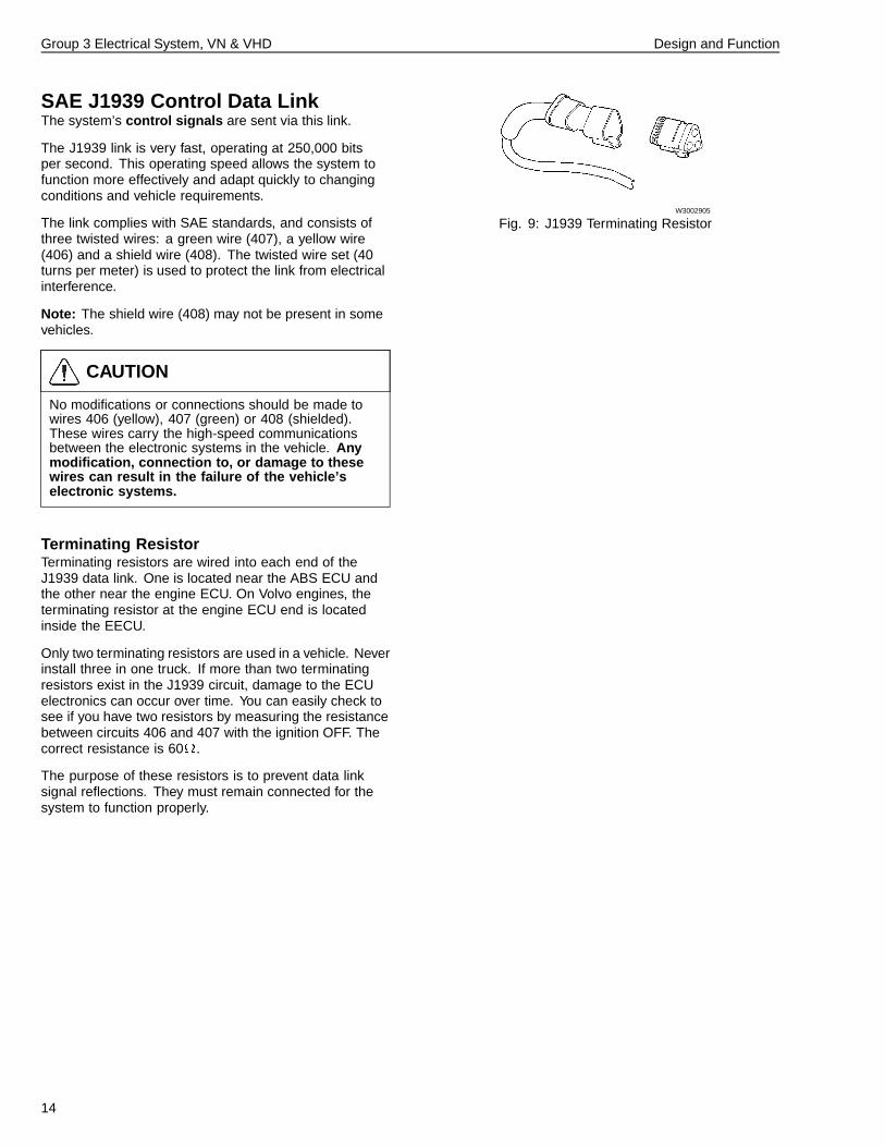
Terminating ResistorTerminating resistors are wired into each end of theJ1939 data link. One is located near the ABS ECU andthe other near the engine ECU. On Volvo engines, theterminating resistor at the engine ECU end is locatedinside the EECU.
Only two terminating resistors are used in a vehicle. Neverinstall three in one truck. If more than two terminatingresistors exist in the J1939 circuit, damage to the ECUelectronics can occur over time. You can easily check tosee if you have two resistors by measuring the resistancebetween circuits 406 and 407 with the ignition OFF. Thecorrect resistance is 60 .
The purpose of these resistors is to prevent data linksignal reflections. They must remain connected for thesystem to function properly.
W3002905
Fig. 9: J1939 Terminating Resistor
14
Group 3 Electrical System, VN & VHD Design and Function
SAE J1587/1708 Information DataLinkInformation and diagnostic signals are sent via thislink. The link also functions as a “backup” should theJ1939 control data link fail to function for any reason.
SAE J1708 is a standard that specifies hardware and adatabus speed of 9600 bits per second. SAE J1587 is aprotocol that provides a standard method for exchanginginformation between microprocessors.
The J1587 link consists of two wires (400 and 401) thatare twisted around each other approx. 30 turns per meter.The twisted-pair wires are to protect the link againstelectrical interference.
CAUTION
If a circuit must be added to the electrical system,and will carry high currents or frequencies, route it ina location AWAY from wires 400 and 401 to preventmutual inductance from interfering with data linkfunctions.
CAUTION
Wires 400 and 401 MUST NOT be cut or spliced for anyconnections. These wires are used for the transmissionof data for diagnostic messages and gauges. Modifyingthis circuit can cause these functions to fail.
SAE J1922 Data LinkFor a short period of time some vehicles were producedwhich used the J1922 data link. The J1922 data link wasdeveloped as an interim standard until the J1939 controldata link was established. The J1922 link operates onJ1708 defined hardware and is used like a control link forcommunication between engine, transmission and ABSECUs.
The J1922 link consists of two wires (404 and 405) thatare twisted around each other approx. 30 turns per meter.The twisted-pair wires are to protect the link againstelectrical interference.
15
Group 3 Electrical System, VN & VHD Design and Function
Diagnostic Connector
W8001310
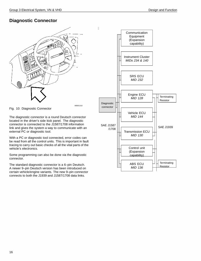
Fig. 10: Diagnostic Connector
The diagnostic connector is a round Deutsch connectorlocated in the driver’s side kick panel. The diagnosticconnector is connected to the J1587/1708 informationlink and gives the system a way to communicate with anexternal PC or diagnostic tool.
With a PC or diagnostic tool connected, error codes canbe read from all the control units. This is important in faulttracing to carry out basic checks of all the vital parts of thevehicle’s electronics.
Some programming can also be done via the diagnosticconnector.
The standard diagnostic connector is a 6–pin Deutsch.A newer 9–pin Deutsch version has been introduced oncertain vehicle/engine variants. The new 9–pin connectorconnects to both the J1939 and J1587/1708 data links.
CommunicationEquipment(Expansioncapability)
Instrument ClusterMIDs 234 & 140
SRS ECUMID 232
Engine ECUMID 128 Terminating
ResistorDiagnosticconnector
Vehicle ECUMID 144
SAE J1587/1708
SAE J1939
Transmission ECUMID 130
Control unit(Expansioncapability)
TerminatingResistor
ABS ECUMID 136
16
Group 3 Electrical System, VN & VHD Design and Function
Starting and Charging System
W3004350
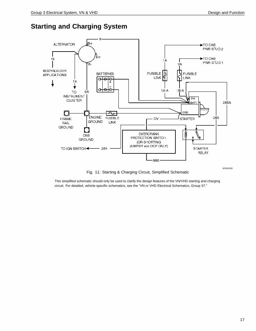
Fig. 11: Starting & Charging Circuit, Simplified Schematic
This simplified schematic should only be used to clarify the design features of the VN/VHD starting and chargingcircuit. For detailed, vehicle-specific schematics, see the “VN or VHD Electrical Schematics, Group 37.”
17
Group 3 Electrical System, VN & VHD Design and Function
Batteries
W3004394
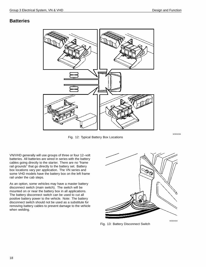
Fig. 12: Typical Battery Box Locations
VN/VHD generally will use groups of three or four 12–voltbatteries. All batteries are wired in series with the batterycables going directly to the starter. There are no “framerail grounds” that go directly to the battery set. Batterybox locations vary per application. The VN series andsome VHD models have the battery box on the left framerail under the cab steps.
As an option, some vehicles may have a master batterydisconnect switch (main switch). The switch will bemounted on or near the battery box in all applications.The battery disconnect switch can be used to cut allpositive battery power to the vehicle. Note: The batterydisconnect switch should not be used as a substitute forremoving battery cables to prevent damage to the vehiclewhen welding.
W3004404
Fig. 13: Battery Disconnect Switch
18
Group 3 Electrical System, VN & VHD Design and Function
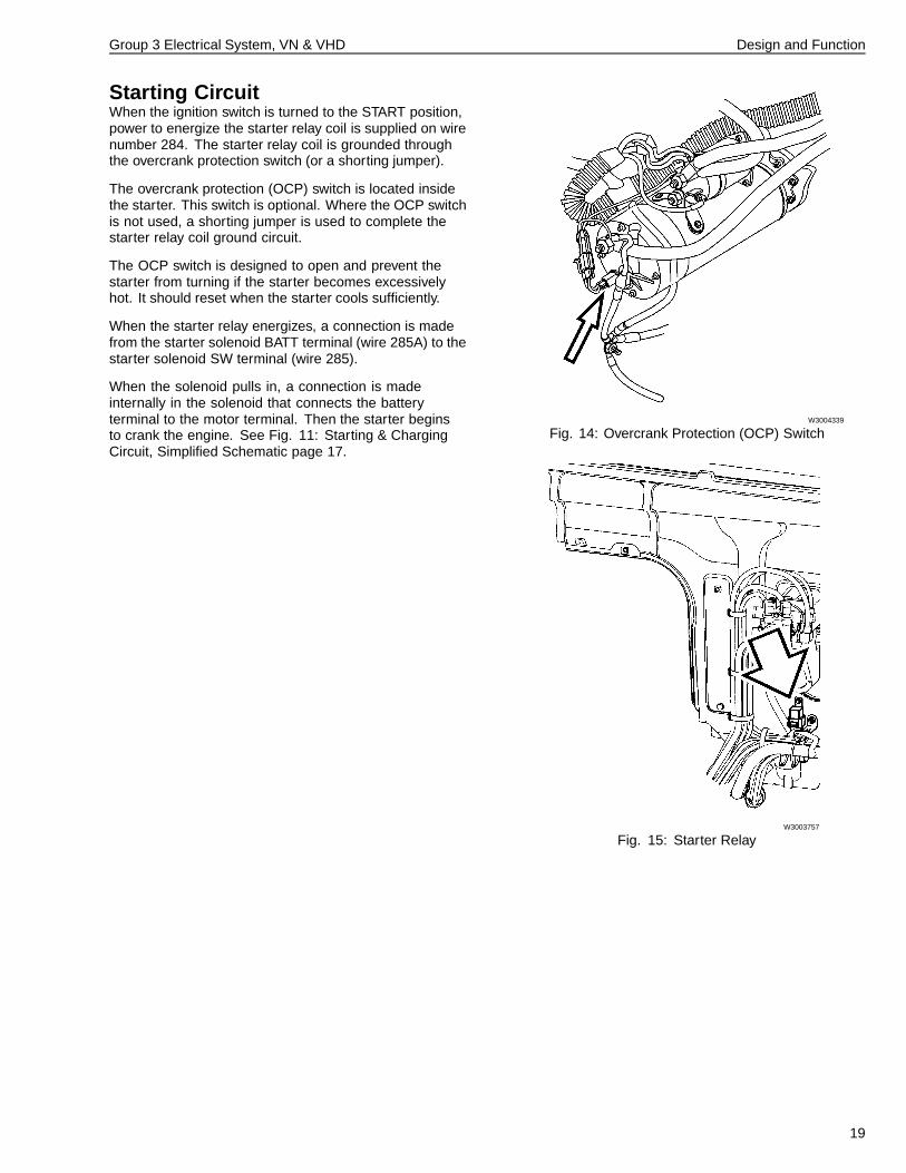
Starting CircuitWhen the ignition switch is turned to the START position,power to energize the starter relay coil is supplied on wirenumber 284. The starter relay coil is grounded throughthe overcrank protection switch (or a shorting jumper).
The overcrank protection (OCP) switch is located insidethe starter. This switch is optional. Where the OCP switchis not used, a shorting jumper is used to complete thestarter relay coil ground circuit.
The OCP switch is designed to open and prevent thestarter from turning if the starter becomes excessivelyhot. It should reset when the starter cools sufficiently.
When the starter relay energizes, a connection is madefrom the starter solenoid BATT terminal (wire 285A) to thestarter solenoid SW terminal (wire 285).
When the solenoid pulls in, a connection is madeinternally in the solenoid that connects the batteryterminal to the motor terminal. Then the starter beginsto crank the engine. See Fig. 11: Starting & ChargingCircuit, Simplified Schematic page 17.
W3004339
Fig. 14: Overcrank Protection (OCP) Switch
W3003757
Fig. 15: Starter Relay
19
Group 3 Electrical System, VN & VHD Design and Function
Charging CircuitWith the engine running, AC voltage is initially generatedin the alternator’s stator windings by passing magneticfields from the rotor.
Diodes in the rectifier bridge change the AC voltage to DCvoltage at the alternator B+ terminal.
As the alternator speed increases, current is providedfor charging the batteries and operating electricalaccessories through wire 8.
An integral voltage regulator maintains operating voltageto a predetermined setting. See Fig. 11: Starting &Charging Circuit, Simplified Schematic page 17.
20
Group 3 Electrical System, VN & VHD Design and Function
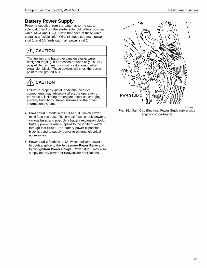
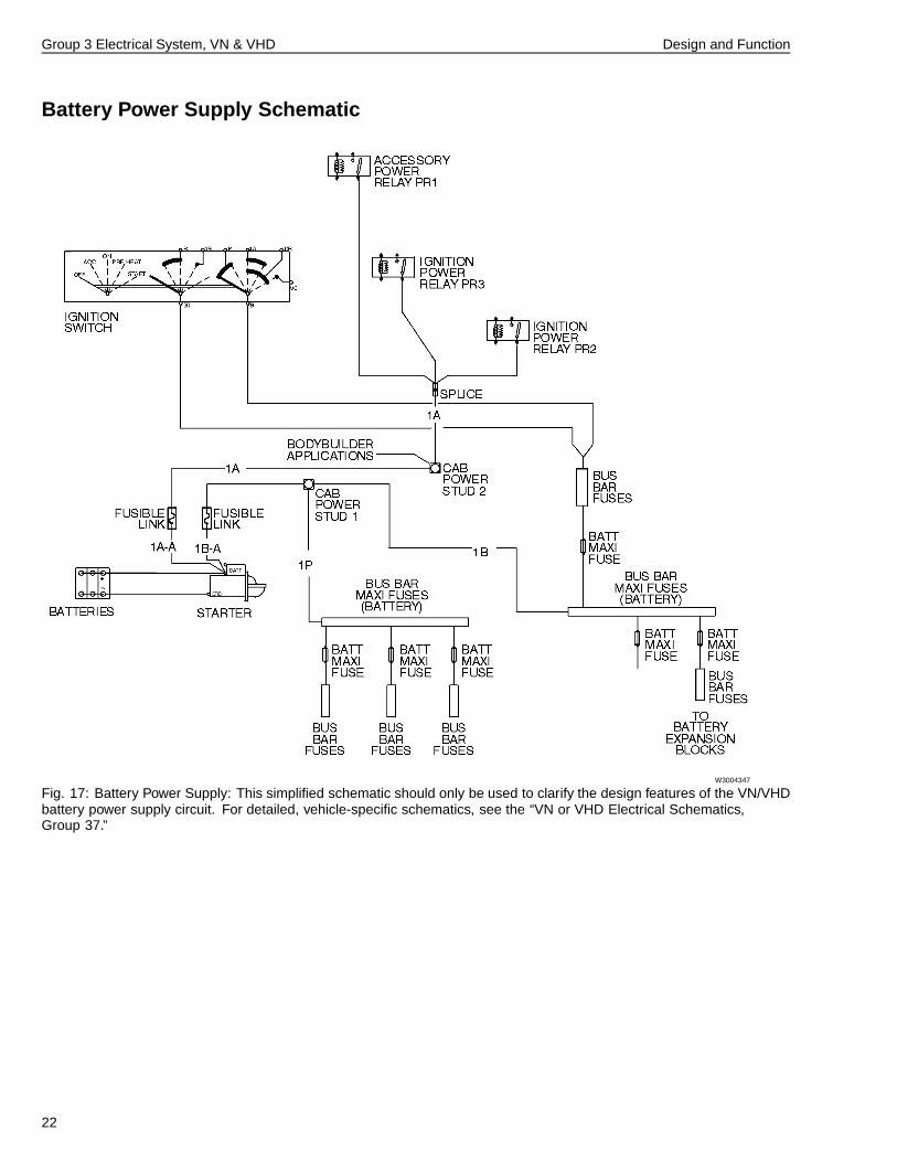
Battery Power SupplyPower is supplied from the batteries to the startersolenoid, then from the starter solenoid battery post viawires 1A–A and 1B–A. (Note that each of these wirescontains a fusible link.) Wire 1B feeds cab main powerstud 1, and 1A feeds cab main power stud 2.
CAUTION
The ignition and battery expansion blocks weredesigned for plug-in harnesses or fuses only. DO NOTplug ATO-size fuses or circuit breakers into eitherexpansion block. These devices will short the powerpoint to the ground bus.
CAUTION
Failure to properly install additional electricalcomponents may adversely affect the operation ofthe vehicle, including the engine, electrical chargingsystem, truck body, stereo system and the driverinformation systems.
• Power stud 1 feeds wires 1B and 1P, which powermaxi-fuse bus bars. These maxi-fuses supply power tovarious fuses and possibly a battery expansion block.Battery power is also supplied to the ignition switchthrough this circuit. The battery power expansionblock is used to supply power to optional electricalaccessories.
• Power stud 2 feeds wire 1A, which delivers powerthrough a splice to the Accessory Power Relay andto two Ignition Power Relays. Power stud 2 may alsosupply battery power for Bodybuilder applications.
W3004399
Fig. 16: Main Cab Electrical Power Studs (driver sideengine compartment)
21
Group 3 Electrical System, VN & VHD Design and Function
Battery Power Supply Schematic
W3004347
Fig. 17: Battery Power Supply: This simplified schematic should only be used to clarify the design features of the VN/VHDbattery power supply circuit. For detailed, vehicle-specific schematics, see the “VN or VHD Electrical Schematics,Group 37.”
22
Group 3 Electrical System, VN & VHD Design and Function
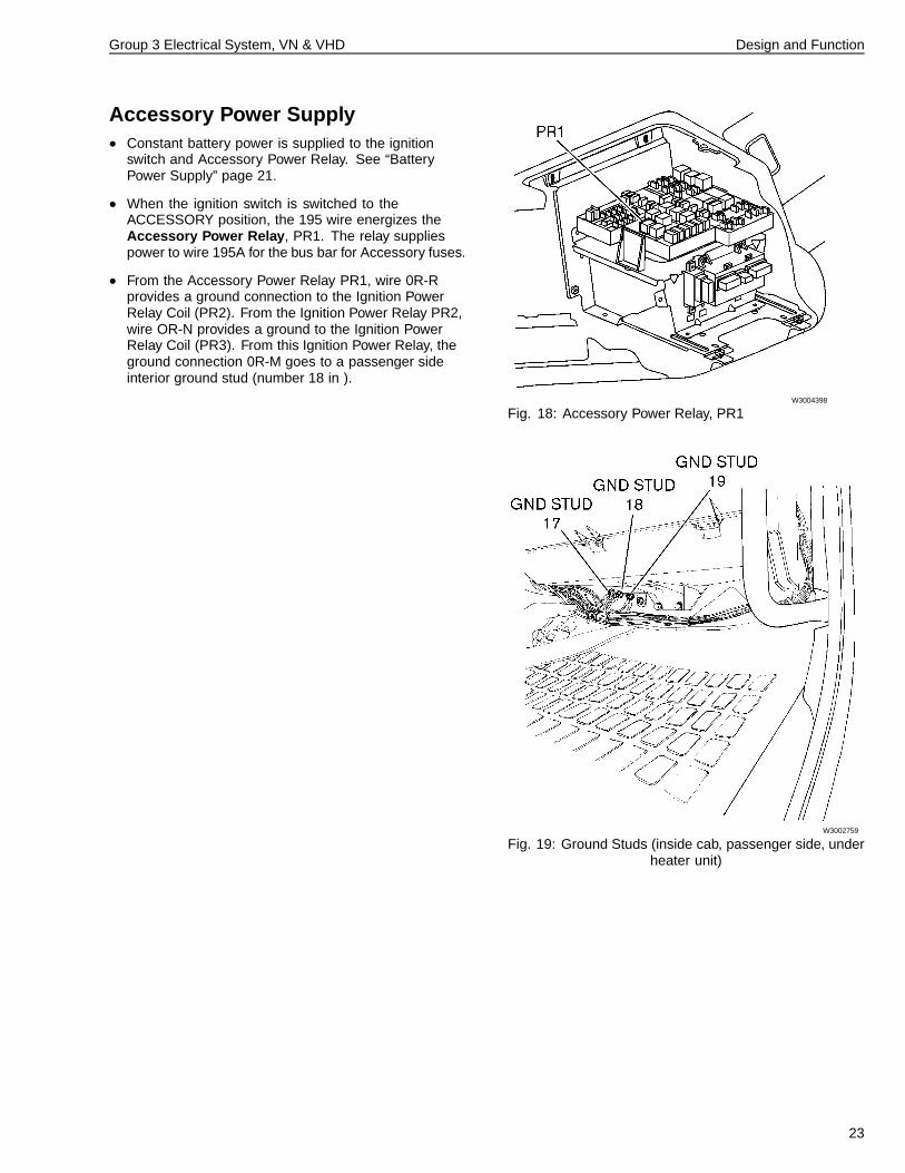
Accessory Power Supply• Constant battery power is supplied to the ignition
switch and Accessory Power Relay. See “BatteryPower Supply” page 21.
• When the ignition switch is switched to theACCESSORY position, the 195 wire energizes theAccessory Power Relay , PR1. The relay suppliespower to wire 195A for the bus bar for Accessory fuses.
• From the Accessory Power Relay PR1, wire 0R-Rprovides a ground connection to the Ignition PowerRelay Coil (PR2). From the Ignition Power Relay PR2,wire OR-N provides a ground to the Ignition PowerRelay Coil (PR3). From this Ignition Power Relay, theground connection 0R-M goes to a passenger sideinterior ground stud (number 18 in ).
W3004398
Fig. 18: Accessory Power Relay, PR1
W3002759
Fig. 19: Ground Studs (inside cab, passenger side, underheater unit)
23
Group 3 Electrical System, VN & VHD Design and Function
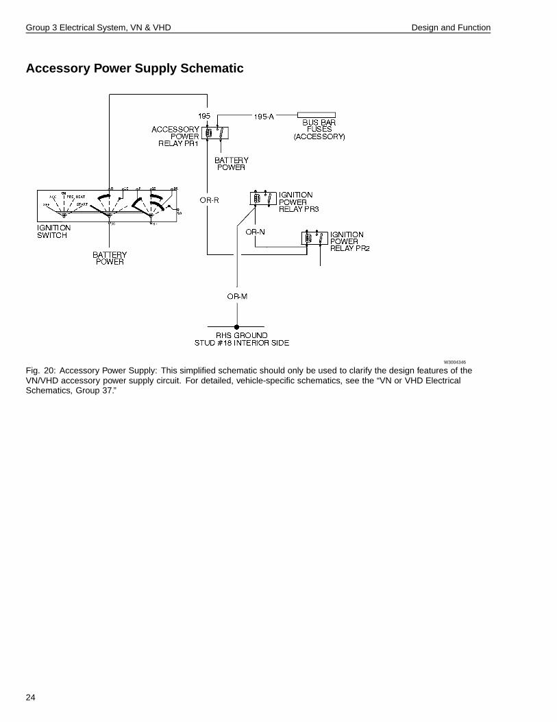
Accessory Power Supply Schematic
W3004346
Fig. 20: Accessory Power Supply: This simplified schematic should only be used to clarify the design features of theVN/VHD accessory power supply circuit. For detailed, vehicle-specific schematics, see the “VN or VHD ElectricalSchematics, Group 37.”
24
Group 3 Electrical System, VN & VHD Design and Function
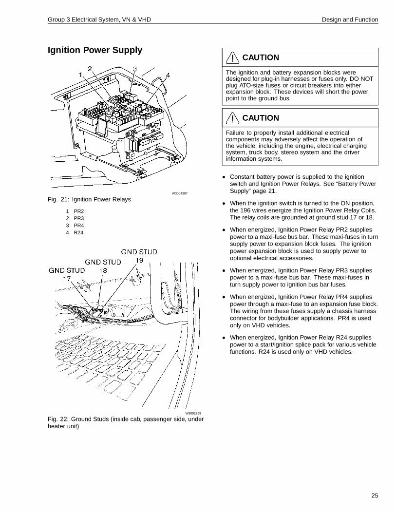
Ignition Power Supply
W3004397
Fig. 21: Ignition Power Relays
1 PR22 PR33 PR44 R24
W3002759
Fig. 22: Ground Studs (inside cab, passenger side, underheater unit)
CAUTION
The ignition and battery expansion blocks weredesigned for plug-in harnesses or fuses only. DO NOTplug ATO-size fuses or circuit breakers into eitherexpansion block. These devices will short the powerpoint to the ground bus.
CAUTION
Failure to properly install additional electricalcomponents may adversely affect the operation ofthe vehicle, including the engine, electrical chargingsystem, truck body, stereo system and the driverinformation systems.
• Constant battery power is supplied to the ignitionswitch and Ignition Power Relays. See “Battery PowerSupply” page 21.
• When the ignition switch is turned to the ON position,the 196 wires energize the Ignition Power Relay Coils.The relay coils are grounded at ground stud 17 or 18.
• When energized, Ignition Power Relay PR2 suppliespower to a maxi-fuse bus bar. These maxi-fuses in turnsupply power to expansion block fuses. The ignitionpower expansion block is used to supply power tooptional electrical accessories.
• When energized, Ignition Power Relay PR3 suppliespower to a maxi-fuse bus bar. These maxi-fuses inturn supply power to ignition bus bar fuses.
• When energized, Ignition Power Relay PR4 suppliespower through a maxi-fuse to an expansion fuse block.The wiring from these fuses supply a chassis harnessconnector for bodybuilder applications. PR4 is usedonly on VHD vehicles.
• When energized, Ignition Power Relay R24 suppliespower to a start/ignition splice pack for various vehiclefunctions. R24 is used only on VHD vehicles.
25
Group 3 Electrical System, VN & VHD Design and Function
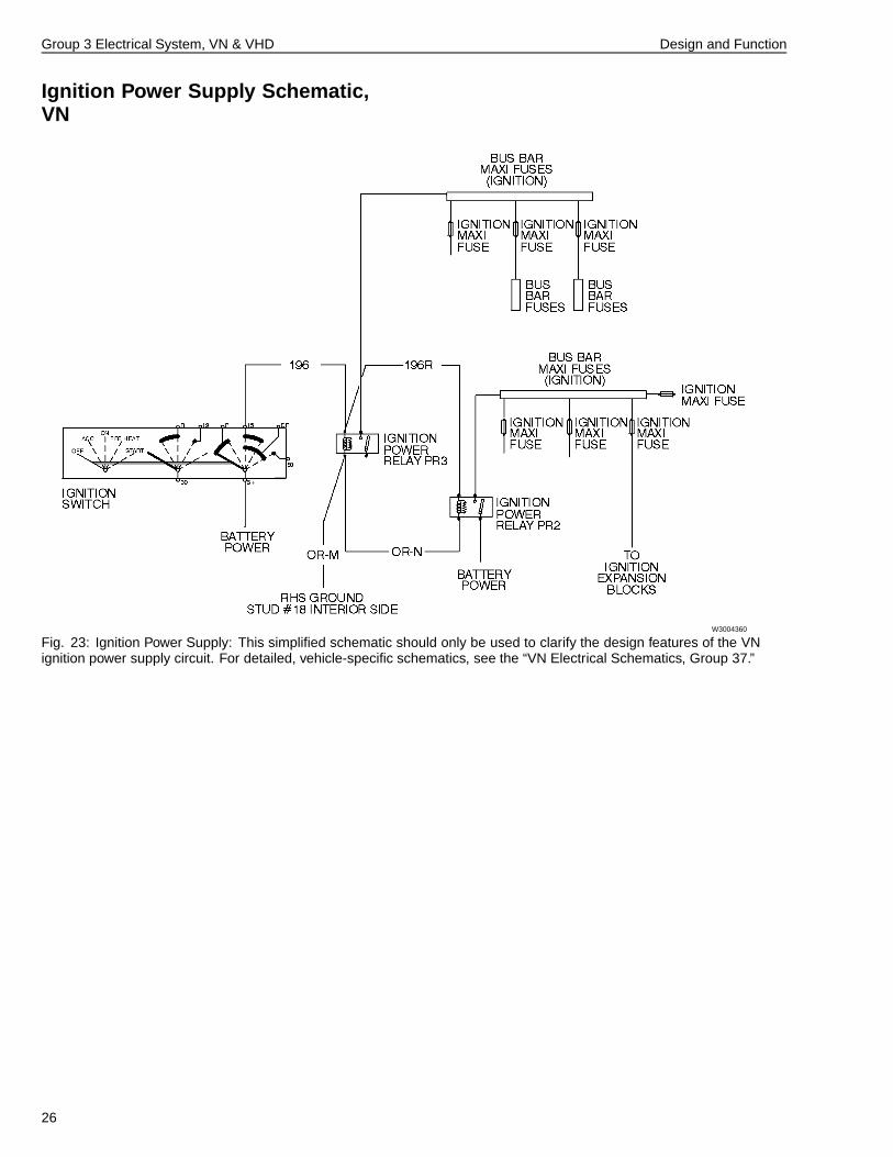
Ignition Power Supply Schematic,VN
W3004360
Fig. 23: Ignition Power Supply: This simplified schematic should only be used to clarify the design features of the VNignition power supply circuit. For detailed, vehicle-specific schematics, see the “VN Electrical Schematics, Group 37.”
26
Group 3 Electrical System, VN & VHD Design and Function
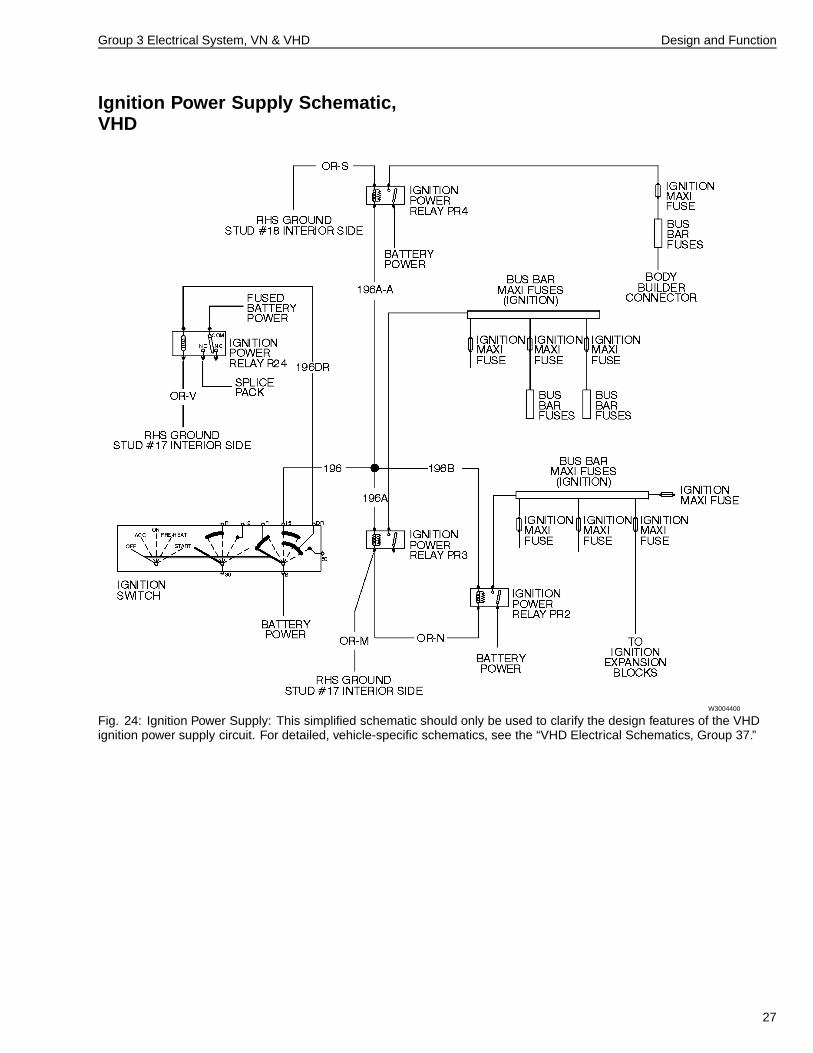
Ignition Power Supply Schematic,VHD
W3004400
Fig. 24: Ignition Power Supply: This simplified schematic should only be used to clarify the design features of the VHDignition power supply circuit. For detailed, vehicle-specific schematics, see the “VHD Electrical Schematics, Group 37.”
27
Group 3 Electrical System, VN & VHD Design and Function
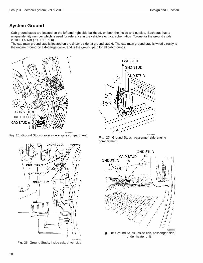
System GroundCab ground studs are located on the left and right side bulkhead, on both the inside and outside. Each stud has aunique identity number which is used for reference in the vehicle electrical schematics. Torque for the ground studsis 10 ± 1.5 Nm (7.4 ± 1.1 ft-lb).The cab main ground stud is located on the driver’s side, at ground stud 6. The cab main ground stud is wired directly tothe engine ground by a 4–gauge cable, and is the ground path for all cab grounds.
W3004401
Fig. 25: Ground Studs, driver side engine compartment
W3000593
Fig. 26: Ground Studs, inside cab, driver side
W3004364
Fig. 27: Ground Studs, passenger side enginecompartment
W3002759
Fig. 28: Ground Studs, inside cab, passenger side,under heater unit
28
Group 3 Electrical System, VN & VHD Design and Function
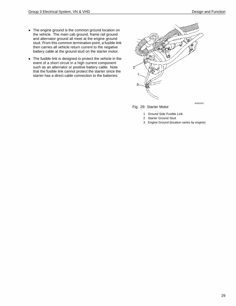
• The engine ground is the common ground location onthe vehicle. The main cab ground, frame rail groundand alternator ground all meet at the engine groundstud. From this common termination point, a fusible linkthen carries all vehicle return current to the negativebattery cable at the ground stud on the starter motor.
• The fusible link is designed to protect the vehicle in theevent of a short circuit in a high current componentsuch as an alternator or positive battery cable. Notethat the fusible link cannot protect the starter since thestarter has a direct cable connection to the batteries.
W3002567
Fig. 29: Starter Motor
1 Ground Side Fusible Link2 Starter Ground Stud3 Engine Ground (location varies by engine)
29
Group 3 Electrical System, VN & VHD Design and Function
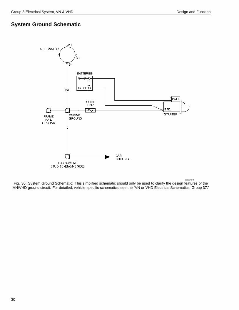
System Ground Schematic
W3004345
Fig. 30: System Ground Schematic: This simplified schematic should only be used to clarify the design features of theVN/VHD ground circuit. For detailed, vehicle-specific schematics, see the “VN or VHD Electrical Schematics, Group 37.”
30
Group 3 Electrical System, VN & VHD Design and Function
Electrical Pass-through for Cab WiringThe two main cab cable pass-throughs are on the leftand right sides of the bulkhead. The pass-throughscontain connectors which join the inner and outer cableharnesses. The passenger side pass-through containswiring for chassis mounted components. The driver’s sidepass-through contains wiring for components mountedunder the hood.
Both pass-throughs consist of a protective outer housingand an attachment plate which holds the connectors inposition. The pass-through covers can be opened fromthe outside.
The cab main power studs are located at the left-handside pass-through. Torque for the main power studs is10 ± 2 Nm (7.4 ± 1.5 ft-lb).
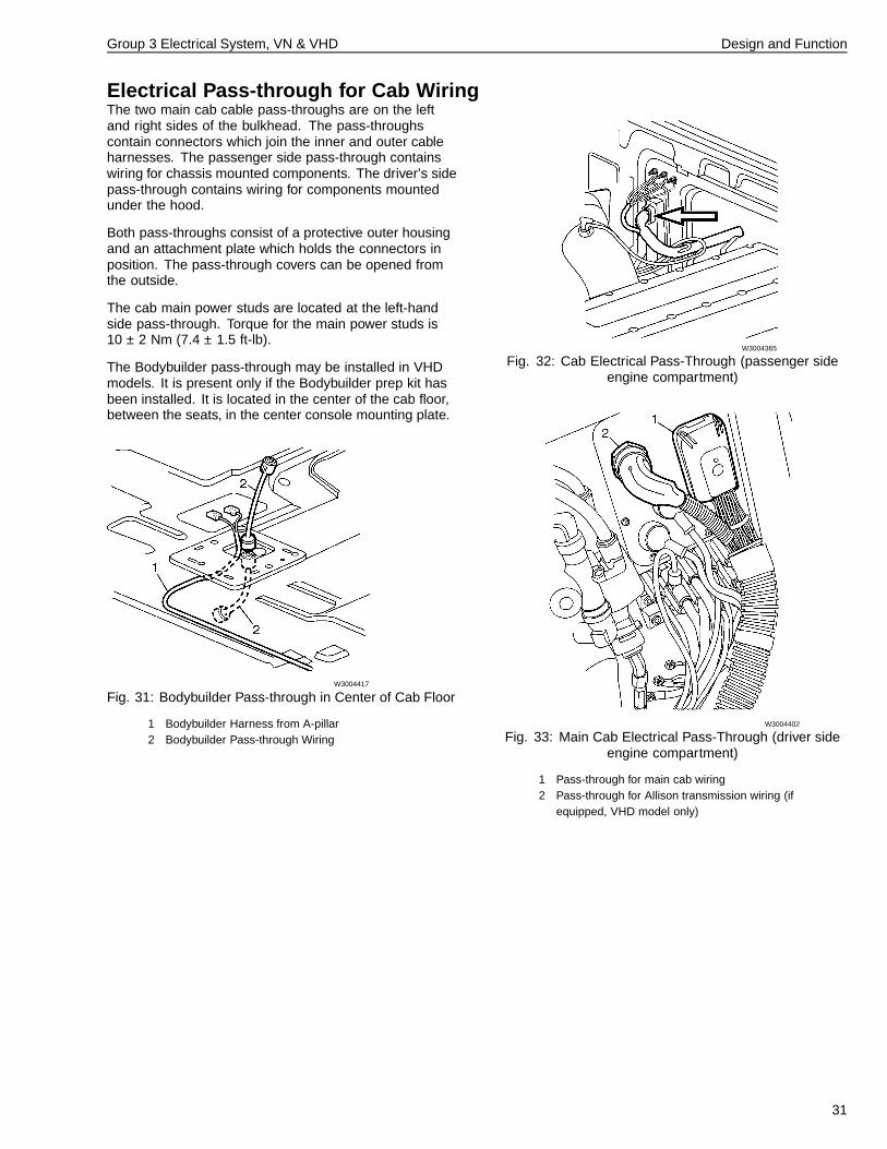
The Bodybuilder pass-through may be installed in VHDmodels. It is present only if the Bodybuilder prep kit hasbeen installed. It is located in the center of the cab floor,between the seats, in the center console mounting plate.
W3004417
Fig. 31: Bodybuilder Pass-through in Center of Cab Floor
1 Bodybuilder Harness from A-pillar2 Bodybuilder Pass-through Wiring
W3004365
Fig. 32: Cab Electrical Pass-Through (passenger sideengine compartment)
W3004402
Fig. 33: Main Cab Electrical Pass-Through (driver sideengine compartment)
1 Pass-through for main cab wiring2 Pass-through for Allison transmission wiring (if
equipped, VHD model only)
31
Group 3 Electrical System, VN & VHD Design and Function
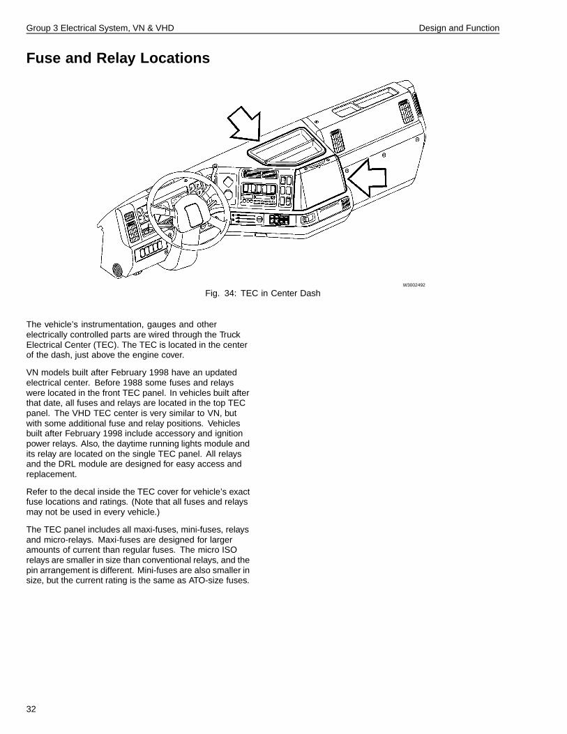
Fuse and Relay Locations
W3002492
Fig. 34: TEC in Center Dash
The vehicle’s instrumentation, gauges and otherelectrically controlled parts are wired through the TruckElectrical Center (TEC). The TEC is located in the centerof the dash, just above the engine cover.
VN models built after February 1998 have an updatedelectrical center. Before 1988 some fuses and relayswere located in the front TEC panel. In vehicles built afterthat date, all fuses and relays are located in the top TECpanel. The VHD TEC center is very similar to VN, butwith some additional fuse and relay positions. Vehiclesbuilt after February 1998 include accessory and ignitionpower relays. Also, the daytime running lights module andits relay are located on the single TEC panel. All relaysand the DRL module are designed for easy access andreplacement.
Refer to the decal inside the TEC cover for vehicle’s exactfuse locations and ratings. (Note that all fuses and relaysmay not be used in every vehicle.)
The TEC panel includes all maxi-fuses, mini-fuses, relaysand micro-relays. Maxi-fuses are designed for largeramounts of current than regular fuses. The micro ISOrelays are smaller in size than conventional relays, and thepin arrangement is different. Mini-fuses are also smaller insize, but the current rating is the same as ATO-size fuses.
32
Group 3 Electrical System, VN & VHD Design and Function
Additional TEC Components
Volvo Engines Only
Located in front of the fuse and relay panel is the VehicleElectronic Control Unit, or VECU (standard with Volvoengines). The VECU is accessible by removing the frontTEC panel. It gathers cab switch and sensor informationand communicates with the engine ECU. Many vehiclefunctions controlled by the combi relay on previousversions of Volvo engines are now controlled by theVECU. For example, the intermittent wiper function onthese vehicles is now controlled by the VECU. For moreinformation on the windshield wiper function, see “VehicleECU” page 55 in this manual.
The central door lock module is mounted to the left of theVECU. The central door lock module is covered later inthis manual. See “Central Door Lock Module” page 56.
33
Group 3 Electrical System, VN & VHD Design and Function
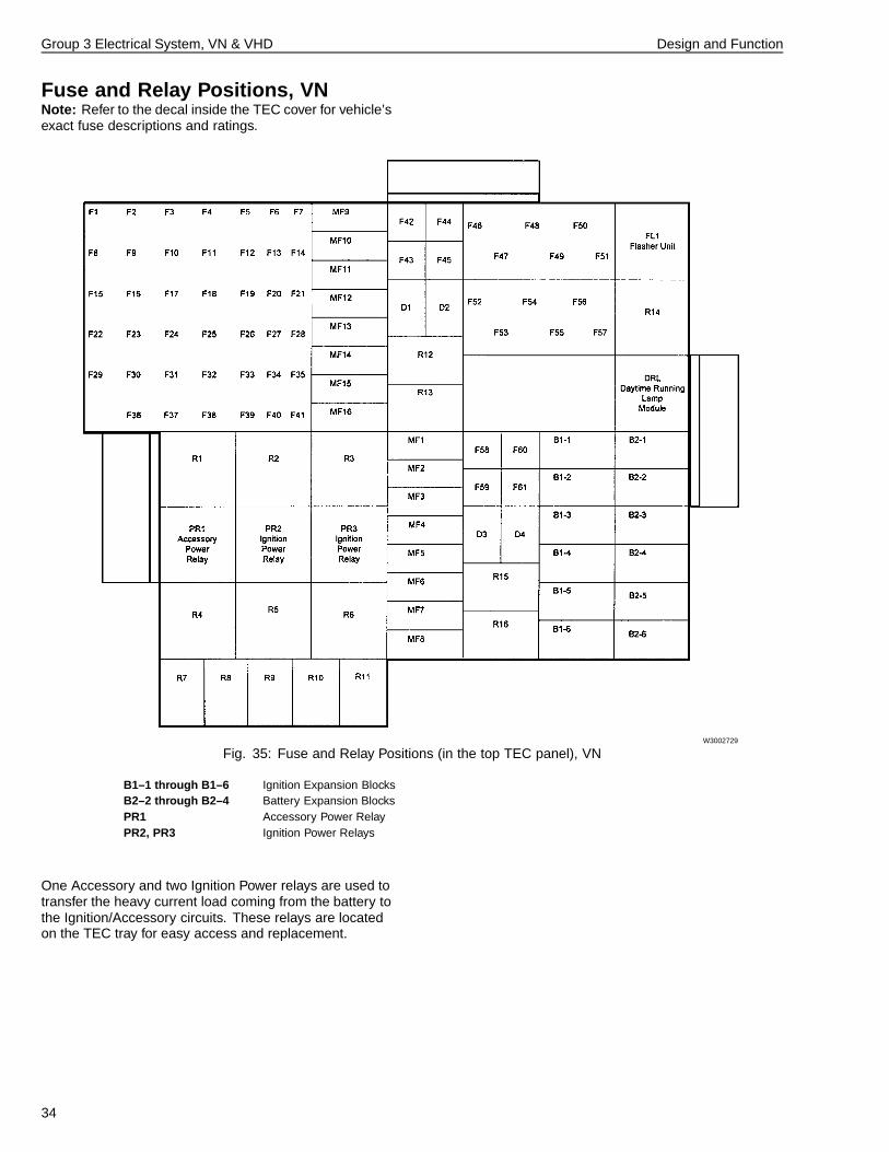
Fuse and Relay Positions, VNNote: Refer to the decal inside the TEC cover for vehicle’sexact fuse descriptions and ratings.
W3002729
Fig. 35: Fuse and Relay Positions (in the top TEC panel), VN
B1–1 through B1–6 Ignition Expansion BlocksB2–2 through B2–4 Battery Expansion BlocksPR1 Accessory Power RelayPR2, PR3 Ignition Power Relays
One Accessory and two Ignition Power relays are used totransfer the heavy current load coming from the battery tothe Ignition/Accessory circuits. These relays are locatedon the TEC tray for easy access and replacement.
34

Group 3 Electrical System, VN & VHD Design and Function
Fuse and Relay Positions, VHDNote: Refer to the decal inside the TEC cover for vehicle’sexact fuse descriptions and ratings.
W3004362
Fig. 36: Fuse and Relay Positions (in the top TEC panel), VHD
B1–1 through B1–6 Battery and Ignition Expansion Blocks
PR1 Accessory Power Relay
PR2, PR3, PR4, R24 Ignition Power Relays
One Accessory and four Ignition Power relays are used totransfer the heavy current load coming from the battery tothe Ignition/Accessory circuits. These relays are locatedon the TEC tray for easy access and replacement. PR4 isused in VHD bodybuilder applications.
35
Group 3 Electrical System, VN & VHD Design and Function
Switches and ControlsDash Switches
W3004361
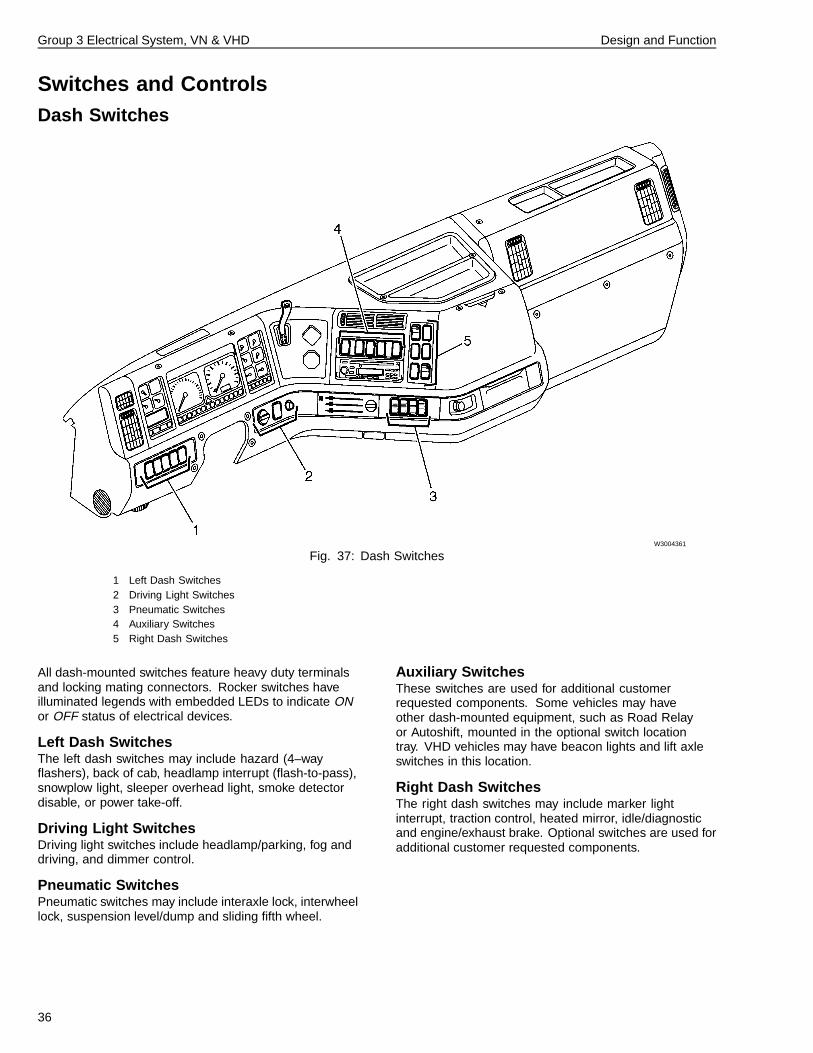
Fig. 37: Dash Switches
1 Left Dash Switches2 Driving Light Switches3 Pneumatic Switches4 Auxiliary Switches5 Right Dash Switches
All dash-mounted switches feature heavy duty terminalsand locking mating connectors. Rocker switches haveilluminated legends with embedded LEDs to indicate ONor OFF status of electrical devices.
Left Dash SwitchesThe left dash switches may include hazard (4–wayflashers), back of cab, headlamp interrupt (flash-to-pass),snowplow light, sleeper overhead light, smoke detectordisable, or power take-off.
Driving Light SwitchesDriving light switches include headlamp/parking, fog anddriving, and dimmer control.
Pneumatic SwitchesPneumatic switches may include interaxle lock, interwheellock, suspension level/dump and sliding fifth wheel.
Auxiliary SwitchesThese switches are used for additional customerrequested components. Some vehicles may haveother dash-mounted equipment, such as Road Relayor Autoshift, mounted in the optional switch locationtray. VHD vehicles may have beacon lights and lift axleswitches in this location.
Right Dash SwitchesThe right dash switches may include marker lightinterrupt, traction control, heated mirror, idle/diagnosticand engine/exhaust brake. Optional switches are used foradditional customer requested components.
36
Group 3 Electrical System, VN & VHD Design and Function
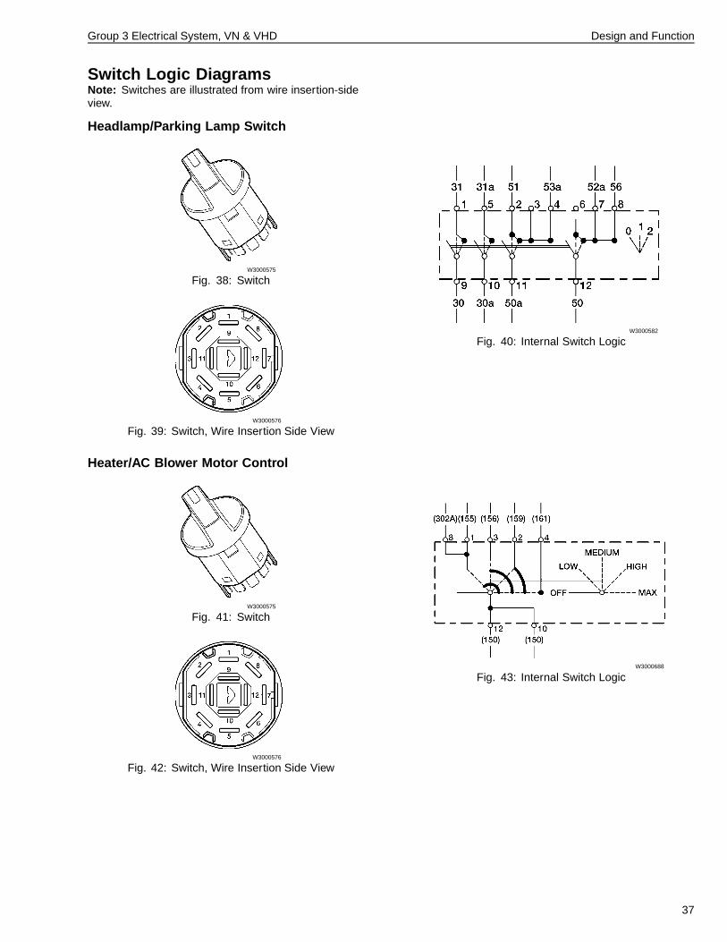
Switch Logic DiagramsNote: Switches are illustrated from wire insertion-sideview.
Headlamp/Parking Lamp Switch
W3000575
Fig. 38: Switch
W3000576
Fig. 39: Switch, Wire Insertion Side View
W3000582
Fig. 40: Internal Switch Logic
Heater/AC Blower Motor Control
W3000575
Fig. 41: Switch
W3000576
Fig. 42: Switch, Wire Insertion Side View
W3000688
Fig. 43: Internal Switch Logic
37
Group 3 Electrical System, VN & VHD Design and Function
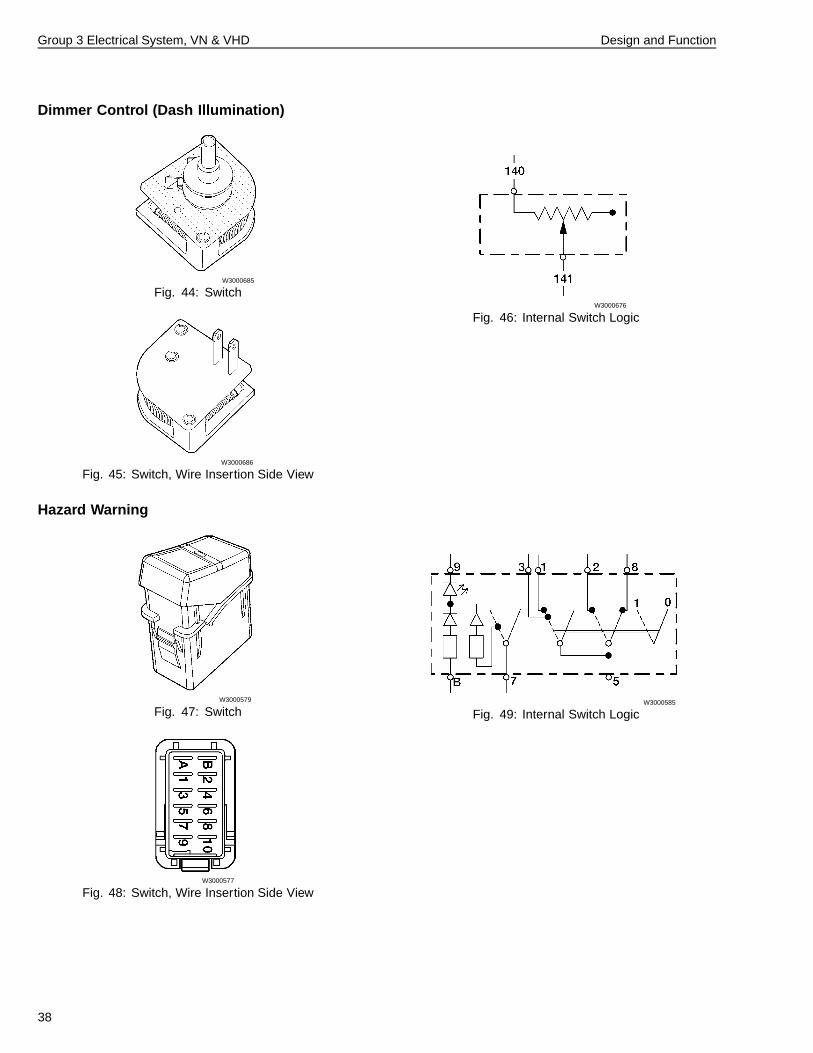
Dimmer Control (Dash Illumination)
W3000685
Fig. 44: Switch
W3000686
Fig. 45: Switch, Wire Insertion Side View
W3000676
Fig. 46: Internal Switch Logic
Hazard Warning
W3000579
Fig. 47: Switch
W3000577
Fig. 48: Switch, Wire Insertion Side View
W3000585
Fig. 49: Internal Switch Logic
38
Group 3 Electrical System, VN & VHD Design and Function
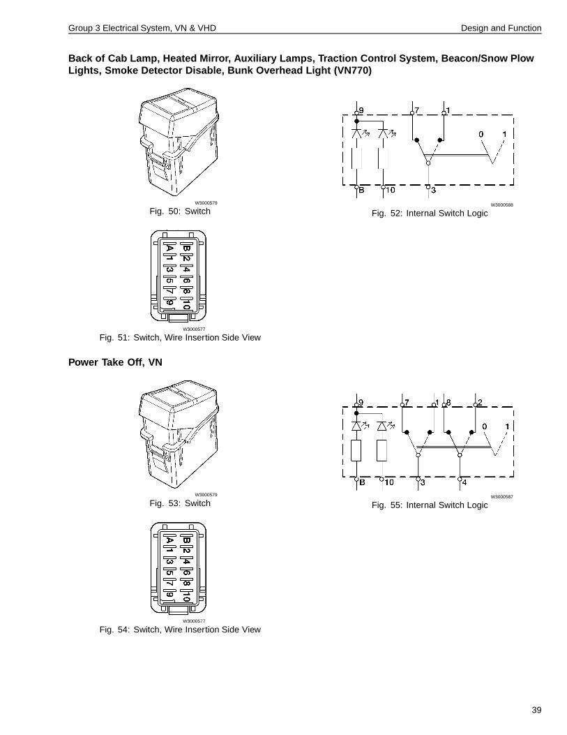
Back of Cab Lamp, Heated Mirror, Auxiliary Lamps, Traction Control System, Beacon/Snow PlowLights, Smoke Detector Disable, Bunk Overhead Light (VN770)
W3000579
Fig. 50: Switch
W3000577
Fig. 51: Switch, Wire Insertion Side View
W3000588
Fig. 52: Internal Switch Logic
Power Take Off, VN
W3000579
Fig. 53: Switch
W3000577
Fig. 54: Switch, Wire Insertion Side View
W3000587
Fig. 55: Internal Switch Logic
39
Group 3 Electrical System, VN & VHD Design and Function
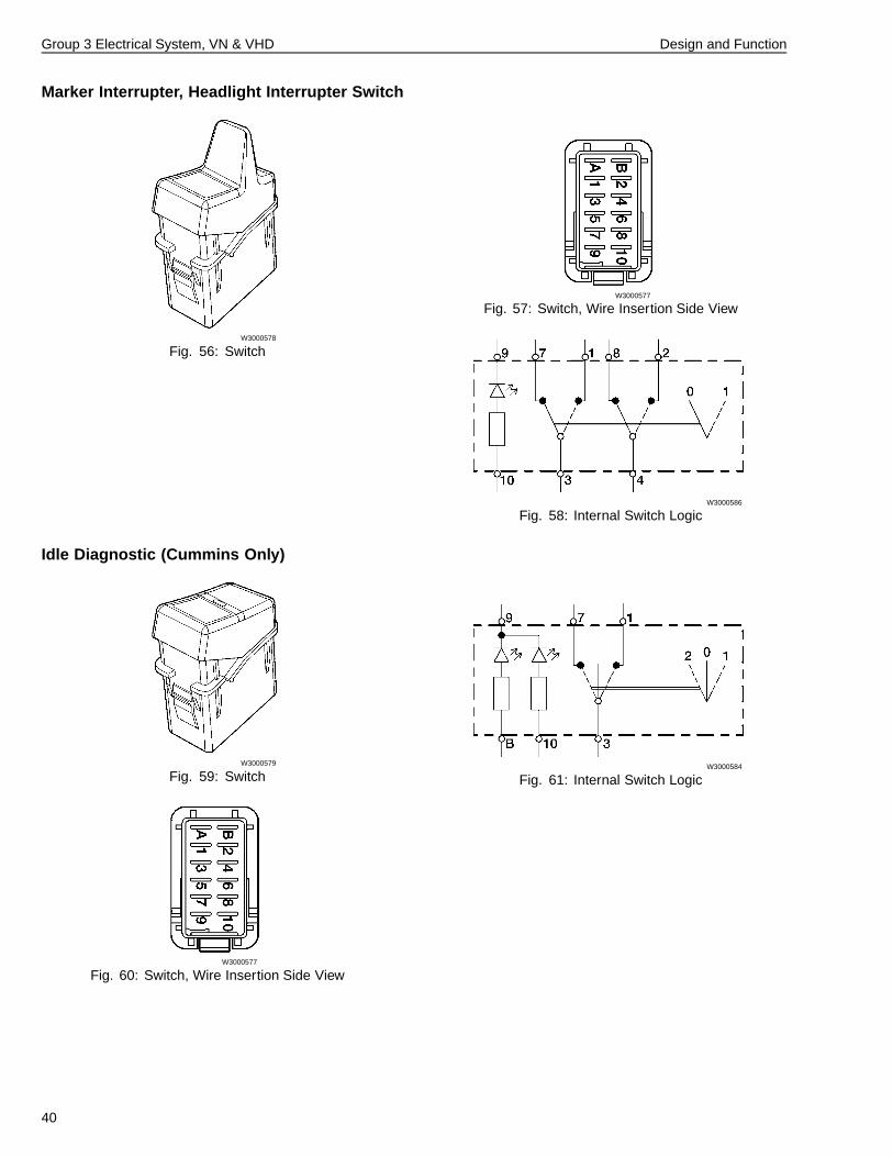
Marker Interrupter, Headlight Interrupter Switch
W3000578
Fig. 56: Switch
W3000577
Fig. 57: Switch, Wire Insertion Side View
W3000586
Fig. 58: Internal Switch Logic
Idle Diagnostic (Cummins Only)
W3000579
Fig. 59: Switch
W3000577
Fig. 60: Switch, Wire Insertion Side View
W3000584
Fig. 61: Internal Switch Logic
40
Group 3 Electrical System, VN & VHD Design and Function
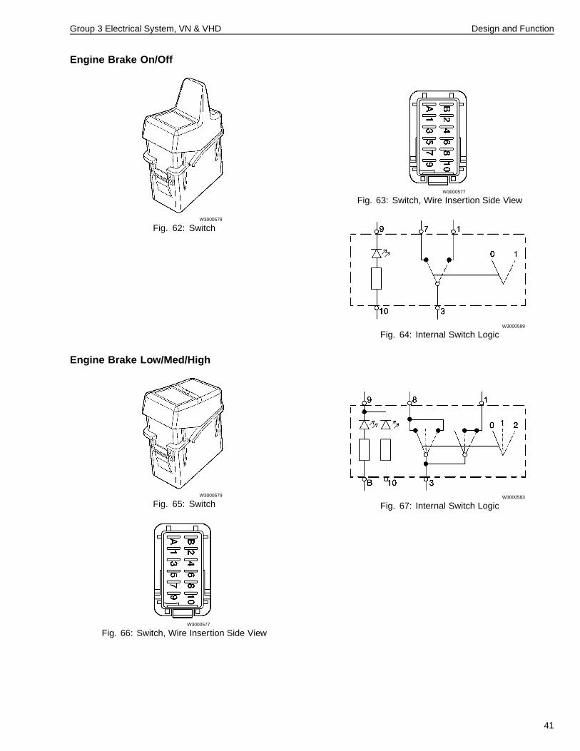
Engine Brake On/Off
W3000578
Fig. 62: Switch
W3000577
Fig. 63: Switch, Wire Insertion Side View
W3000589
Fig. 64: Internal Switch Logic
Engine Brake Low/Med/High
W3000579
Fig. 65: Switch
W3000577
Fig. 66: Switch, Wire Insertion Side View
W3000583
Fig. 67: Internal Switch Logic
41
Group 3 Electrical System, VN & VHD Design and Function
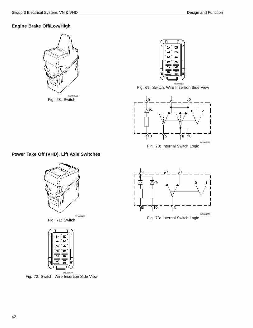
Engine Brake Off/Low/High
W3000578
Fig. 68: Switch
W3000577
Fig. 69: Switch, Wire Insertion Side View
W3000597
Fig. 70: Internal Switch Logic
Power Take Off (VHD), Lift Axle Switches
W3004415
Fig. 71: Switch
W3000577
Fig. 72: Switch, Wire Insertion Side View
W3004363
Fig. 73: Internal Switch Logic
42
Group 3 Electrical System, VN & VHD Design and Function
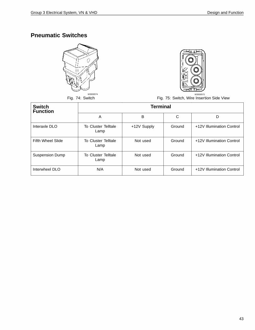
Pneumatic Switches
W3000574
Fig. 74: SwitchW3000573
Fig. 75: Switch, Wire Insertion Side View
TerminalSwitchFunction
A B C D
Interaxle DLO To Cluster TelltaleLamp
+12V Supply Ground +12V Illumination Control
Fifth Wheel Slide To Cluster TelltaleLamp
Not used Ground +12V Illumination Control
Suspension Dump To Cluster TelltaleLamp
Not used Ground +12V Illumination Control
Interwheel DLO N/A Not used Ground +12V Illumination Control
43
Group 3 Electrical System, VN & VHD Design and Function
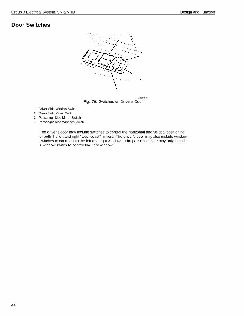
Door Switches
W3004338
Fig. 76: Switches on Driver’s Door
1 Driver Side Window Switch2 Driver Side Mirror Switch3 Passenger Side Mirror Switch4 Passenger Side Window Switch
The driver’s door may include switches to control the horizontal and vertical positioningof both the left and right “west coast” mirrors. The driver’s door may also include windowswitches to control both the left and right windows. The passenger side may only includea window switch to control the right window.
44
Group 3 Electrical System, VN & VHD Design and Function
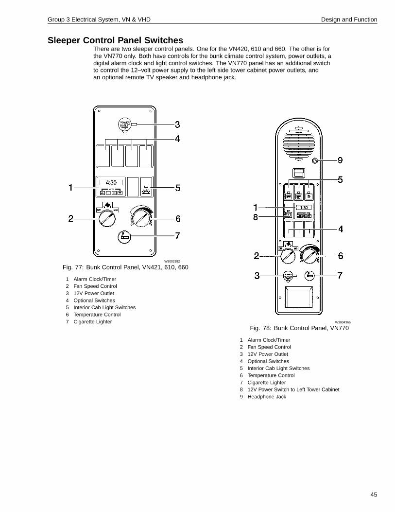
Sleeper Control Panel SwitchesThere are two sleeper control panels. One for the VN420, 610 and 660. The other is forthe VN770 only. Both have controls for the bunk climate control system, power outlets, adigital alarm clock and light control switches. The VN770 panel has an additional switchto control the 12–volt power supply to the left side tower cabinet power outlets, andan optional remote TV speaker and headphone jack.
W8002382
Fig. 77: Bunk Control Panel, VN421, 610, 660
1 Alarm Clock/Timer2 Fan Speed Control3 12V Power Outlet4 Optional Switches5 Interior Cab Light Switches6 Temperature Control7 Cigarette Lighter W3004366
Fig. 78: Bunk Control Panel, VN770
1 Alarm Clock/Timer2 Fan Speed Control3 12V Power Outlet4 Optional Switches5 Interior Cab Light Switches6 Temperature Control7 Cigarette Lighter8 12V Power Switch to Left Tower Cabinet9 Headphone Jack
45
Group 3 Electrical System, VN & VHD Design and Function
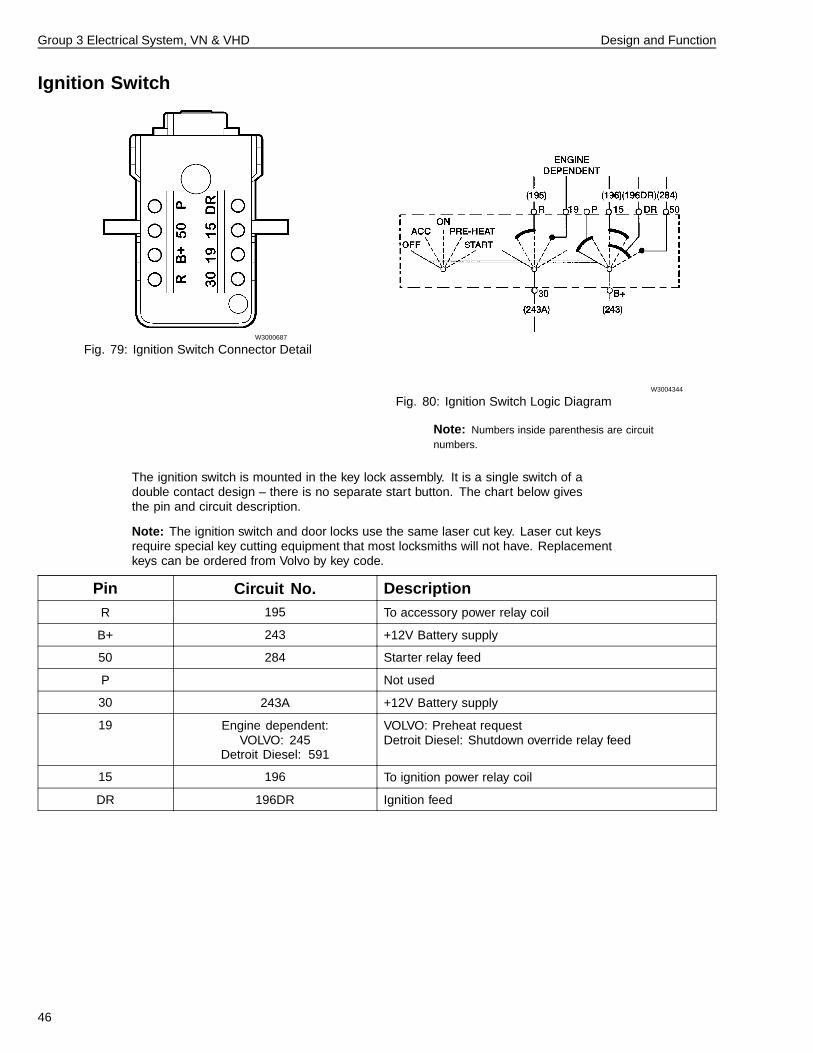
Ignition Switch
W3000687
Fig. 79: Ignition Switch Connector Detail
W3004344
Fig. 80: Ignition Switch Logic Diagram
Note: Numbers inside parenthesis are circuitnumbers.
The ignition switch is mounted in the key lock assembly. It is a single switch of adouble contact design – there is no separate start button. The chart below givesthe pin and circuit description.
Note: The ignition switch and door locks use the same laser cut key. Laser cut keysrequire special key cutting equipment that most locksmiths will not have. Replacementkeys can be ordered from Volvo by key code.
Pin Circuit No. DescriptionR 195 To accessory power relay coil
B+ 243 +12V Battery supply
50 284 Starter relay feed
P Not used
30 243A +12V Battery supply
19 Engine dependent:VOLVO: 245
Detroit Diesel: 591
VOLVO: Preheat requestDetroit Diesel: Shutdown override relay feed
15 196 To ignition power relay coil
DR 196DR Ignition feed
46
Group 3 Electrical System, VN & VHD Design and Function
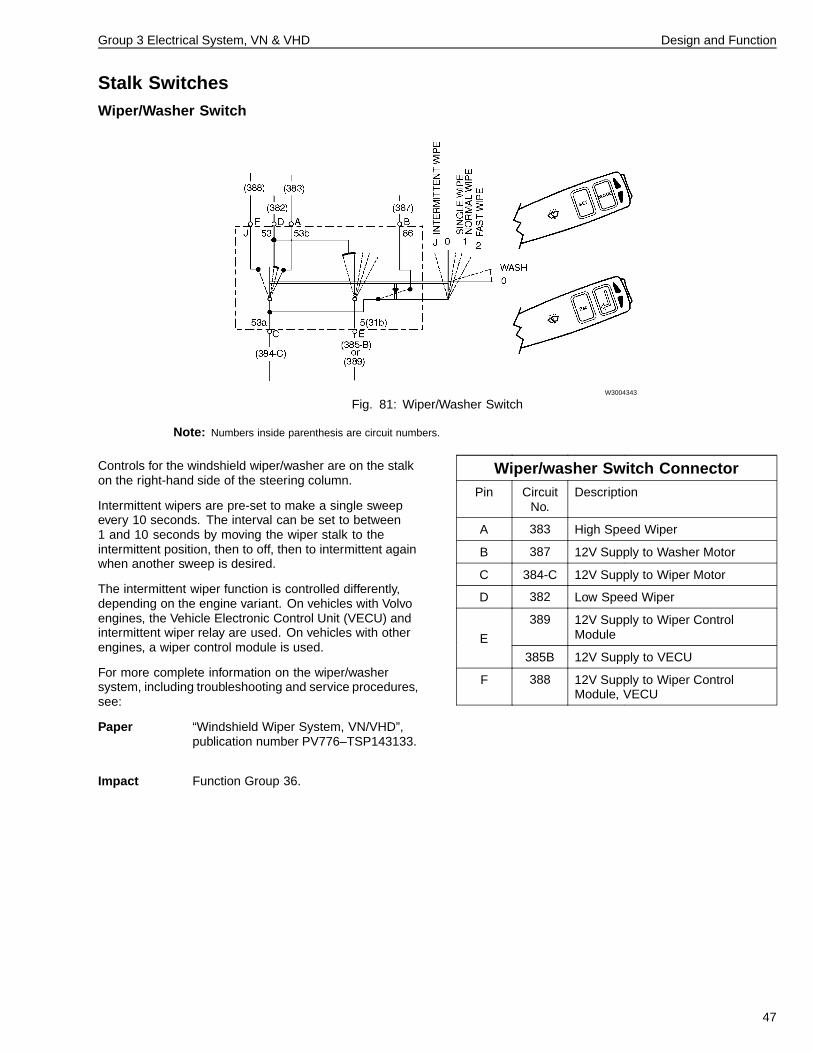
Stalk SwitchesWiper/Washer Switch
W3004343
Fig. 81: Wiper/Washer Switch
Note: Numbers inside parenthesis are circuit numbers.
Controls for the windshield wiper/washer are on the stalkon the right-hand side of the steering column.
Intermittent wipers are pre-set to make a single sweepevery 10 seconds. The interval can be set to between1 and 10 seconds by moving the wiper stalk to theintermittent position, then to off, then to intermittent againwhen another sweep is desired.
The intermittent wiper function is controlled differently,depending on the engine variant. On vehicles with Volvoengines, the Vehicle Electronic Control Unit (VECU) andintermittent wiper relay are used. On vehicles with otherengines, a wiper control module is used.
For more complete information on the wiper/washersystem, including troubleshooting and service procedures,see:
Paper “Windshield Wiper System, VN/VHD”,publication number PV776–TSP143133.
Impact Function Group 36.
Wiper/washer Switch ConnectorPin Circuit
No.Description
A 383 High Speed Wiper
B 387 12V Supply to Washer Motor
C 384-C 12V Supply to Wiper Motor
D 382 Low Speed Wiper
389 12V Supply to Wiper ControlModuleE
385B 12V Supply to VECU
F 388 12V Supply to Wiper ControlModule, VECU
47
Group 3 Electrical System, VN & VHD Design and Function
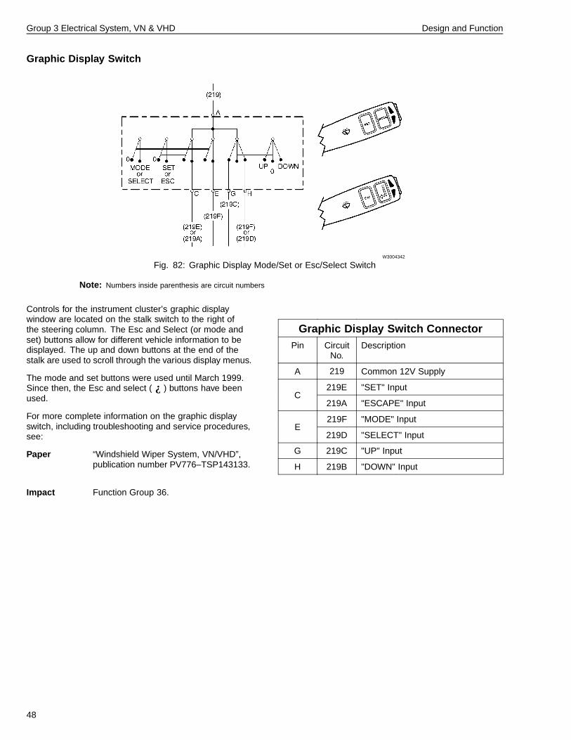
Graphic Display Switch
W3004342
Fig. 82: Graphic Display Mode/Set or Esc/Select Switch
Note: Numbers inside parenthesis are circuit numbers
Controls for the instrument cluster’s graphic displaywindow are located on the stalk switch to the right ofthe steering column. The Esc and Select (or mode andset) buttons allow for different vehicle information to bedisplayed. The up and down buttons at the end of thestalk are used to scroll through the various display menus.
The mode and set buttons were used until March 1999.Since then, the Esc and select ( ¿ ) buttons have beenused.
For more complete information on the graphic displayswitch, including troubleshooting and service procedures,see:
Paper “Windshield Wiper System, VN/VHD”,publication number PV776–TSP143133.
Impact Function Group 36.
Graphic Display Switch ConnectorPin Circuit
No.Description
A 219 Common 12V Supply
219E "SET" InputC
219A "ESCAPE" Input
219F "MODE" InputE
219D "SELECT" Input
G 219C "UP" Input
H 219B "DOWN" Input
48
Group 3 Electrical System, VN & VHD Design and Function
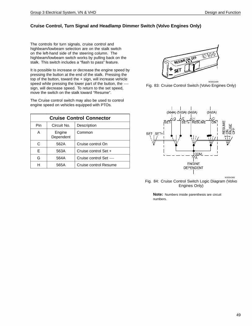
Cruise Control, Turn Signal and Headlamp Dimmer Switch (Volvo Engines Only)
The controls for turn signals, cruise control andhighbeam/lowbeam selection are on the stalk switchon the left-hand side of the steering column. Thehighbeam/lowbeam switch works by pulling back on thestalk. This switch includes a “flash to pass” feature.
It is possible to increase or decrease the engine speed bypressing the button at the end of the stalk. Pressing thetop of the button, toward the + sign, will increase vehiclespeed while pressing the lower part of the button, the �sign, will decrease speed. To return to the set speed,move the switch on the stalk toward “Resume”.
The Cruise control switch may also be used to controlengine speed on vehicles equipped with PTOs.
Cruise Control ConnectorPin Circuit No. Description
A EngineDependent
Common
C 562A Cruise control On
E 563A Cruise control Set +
G 564A Cruise control Set �
H 565A Cruise control Resume
W3002499
Fig. 83: Cruise Control Switch (Volvo Engines Only)
W3004386
Fig. 84: Cruise Control Switch Logic Diagram (VolvoEngines Only)
Note: Numbers inside parenthesis are circuitnumbers.
49
Group 3 Electrical System, VN & VHD Design and Function
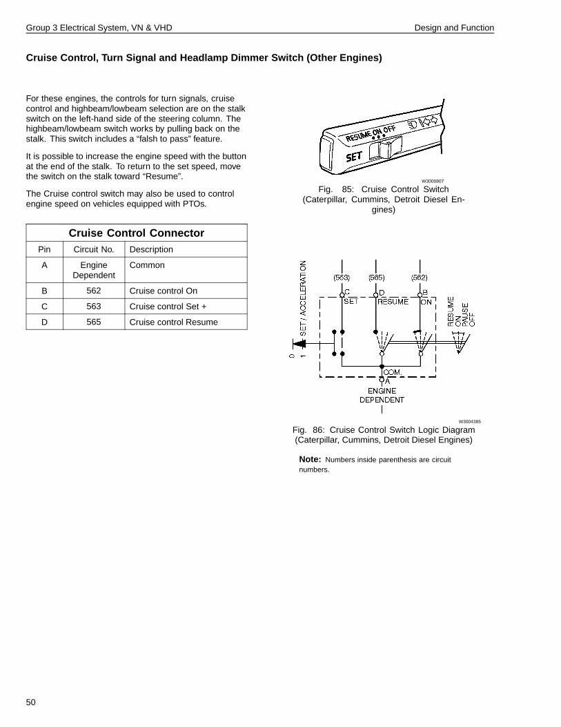
Cruise Control, Turn Signal and Headlamp Dimmer Switch (Other Engines)
For these engines, the controls for turn signals, cruisecontrol and highbeam/lowbeam selection are on the stalkswitch on the left-hand side of the steering column. Thehighbeam/lowbeam switch works by pulling back on thestalk. This switch includes a “falsh to pass” feature.
It is possible to increase the engine speed with the buttonat the end of the stalk. To return to the set speed, movethe switch on the stalk toward “Resume”.
The Cruise control switch may also be used to controlengine speed on vehicles equipped with PTOs.
Cruise Control ConnectorPin Circuit No. Description
A EngineDependent
Common
B 562 Cruise control On
C 563 Cruise control Set +
D 565 Cruise control Resume
W3000807
Fig. 85: Cruise Control Switch(Caterpillar, Cummins, Detroit Diesel En-
gines)
W3004385
Fig. 86: Cruise Control Switch Logic Diagram(Caterpillar, Cummins, Detroit Diesel Engines)
Note: Numbers inside parenthesis are circuitnumbers.
50
Group 3 Electrical System, VN & VHD Design and Function
W3004427
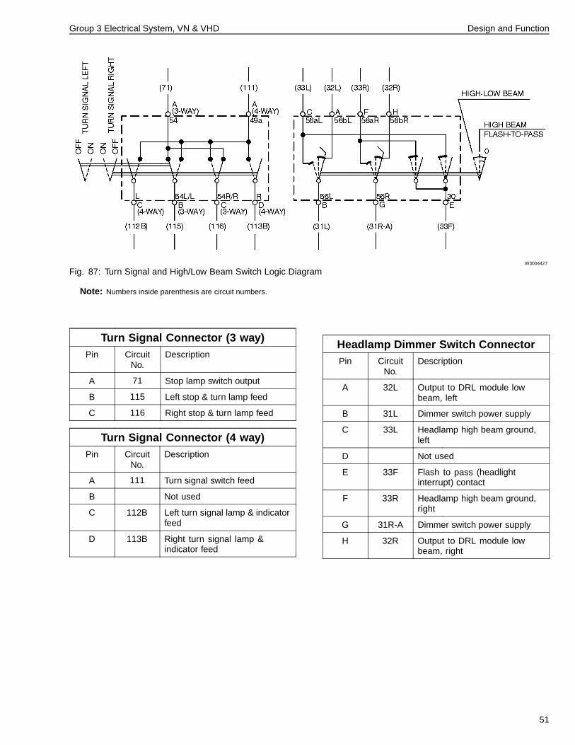
Fig. 87: Turn Signal and High/Low Beam Switch Logic Diagram
Note: Numbers inside parenthesis are circuit numbers.
Turn Signal Connector (3 way)Pin Circuit
No.Description
A 71 Stop lamp switch output
B 115 Left stop & turn lamp feed
C 116 Right stop & turn lamp feed
Turn Signal Connector (4 way)Pin Circuit
No.Description
A 111 Turn signal switch feed
B Not used
C 112B Left turn signal lamp & indicatorfeed
D 113B Right turn signal lamp &indicator feed
Headlamp Dimmer Switch ConnectorPin Circuit
No.Description
A 32L Output to DRL module lowbeam, left
B 31L Dimmer switch power supply
C 33L Headlamp high beam ground,left
D Not used
E 33F Flash to pass (headlightinterrupt) contact
F 33R Headlamp high beam ground,right
G 31R-A Dimmer switch power supply
H 32R Output to DRL module lowbeam, right
51
Group 3 Electrical System, VN & VHD Design and Function
Instrumentation
W3004310
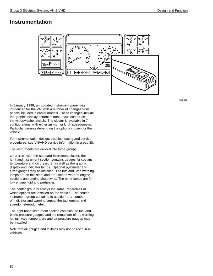
In January 1998, an updated instrument panel wasintroduced for the VN, with a number of changes frompanels included in earlier models. These changes includethe graphic display control buttons, now located onthe wiper/washer switch. The cluster is available in 7configurations, with either an mph or km/h speedometer.Particular variants depend on the options chosen for thevehicle.
For instrumentation design, troubleshooting and serviceprocedures, see VN/VHD service information in group 38.
The instruments are divided into three groups:
On a truck with the standard instrument cluster, theleft-hand instrument section contains gauges for coolanttemperature and oil pressure, as well as the graphicdisplay and indicator lamps. Optional pyrometer andturbo gauges may be installed. The Info and Stop warninglamps are on this side, and are used to warn of enginecautions and engine shutdowns. The other lamps are forlow engine fluid and preheater.
The center group is always the same, regardless ofwhich options are installed on the vehicle. The centerinstrument group contains, in addition to a numberof indicator and warning lamps, the tachometer andspeedometer/odometer.
The right-hand instrument section contains the fuel andbrake pressure gauges, and the remainder of the warninglamps. Axle temperature and air pressure gauges maybe installed.
Note that all gauges and telltales may not be used in allvehicles.
52
Group 3 Electrical System, VN & VHD Design and Function
Lighting SystemThe lighting system of the VN/VHD series may incorporate different design lampassemblies for each vehicle type. The headlights on the VN use replaceable halogenbulbs that fit into a reflector housing. The VHD uses the more traditional sealed beambulbs.
Daytime running lights turn the low beam headlights on whenever the ignition switchis on and the park brake is released.
Fog and driving lights are available. When switched on, these lights will alternatebetween fog lights with the headlamp low beams on, and driving lights with theheadlamp high beams on.
For more information on the lighting system, including design and function,troubleshooting and service procedures, see the service information on lighting inGroup 35.
53
Group 3 Electrical System, VN & VHD Design and Function
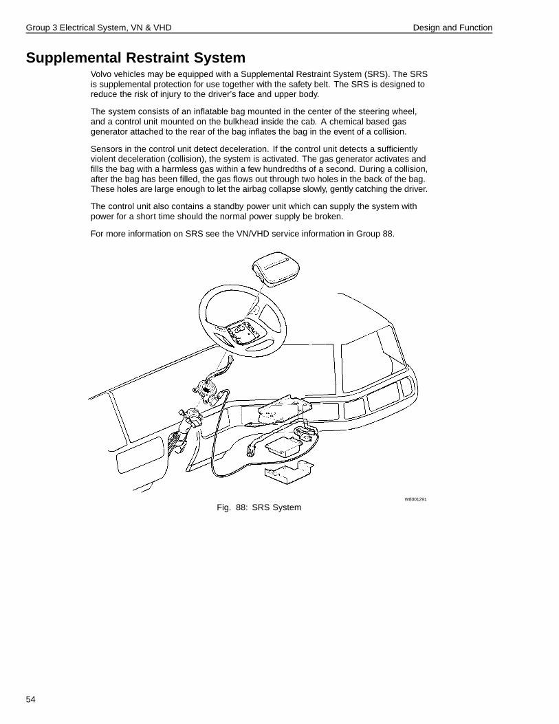
Supplemental Restraint SystemVolvo vehicles may be equipped with a Supplemental Restraint System (SRS). The SRSis supplemental protection for use together with the safety belt. The SRS is designed toreduce the risk of injury to the driver’s face and upper body.
The system consists of an inflatable bag mounted in the center of the steering wheel,and a control unit mounted on the bulkhead inside the cab. A chemical based gasgenerator attached to the rear of the bag inflates the bag in the event of a collision.
Sensors in the control unit detect deceleration. If the control unit detects a sufficientlyviolent deceleration (collision), the system is activated. The gas generator activates andfills the bag with a harmless gas within a few hundredths of a second. During a collision,after the bag has been filled, the gas flows out through two holes in the back of the bag.These holes are large enough to let the airbag collapse slowly, gently catching the driver.
The control unit also contains a standby power unit which can supply the system withpower for a short time should the normal power supply be broken.
For more information on SRS see the VN/VHD service information in Group 88.
W8001291
Fig. 88: SRS System
54
Group 3 Electrical System, VN & VHD Design and Function
Vehicle ECU
W2002673
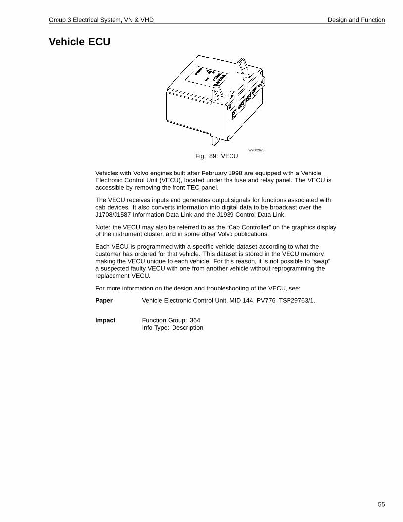
Fig. 89: VECU
Vehicles with Volvo engines built after February 1998 are equipped with a VehicleElectronic Control Unit (VECU), located under the fuse and relay panel. The VECU isaccessible by removing the front TEC panel.
The VECU receives inputs and generates output signals for functions associated withcab devices. It also converts information into digital data to be broadcast over theJ1708/J1587 Information Data Link and the J1939 Control Data Link.
Note: the VECU may also be referred to as the “Cab Controller” on the graphics displayof the instrument cluster, and in some other Volvo publications.
Each VECU is programmed with a specific vehicle dataset according to what thecustomer has ordered for that vehicle. This dataset is stored in the VECU memory,making the VECU unique to each vehicle. For this reason, it is not possible to “swap”a suspected faulty VECU with one from another vehicle without reprogramming thereplacement VECU.
For more information on the design and troubleshooting of the VECU, see:
Paper Vehicle Electronic Control Unit, MID 144, PV776–TSP29763/1.
Impact Function Group: 364Info Type: Description
55
Group 3 Electrical System, VN & VHD Design and Function
Central Door Lock Module
W3000553
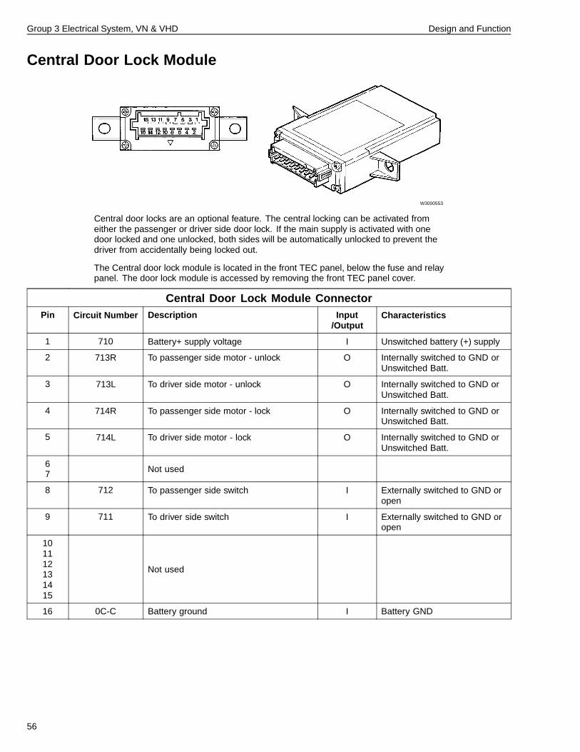
Central door locks are an optional feature. The central locking can be activated fromeither the passenger or driver side door lock. If the main supply is activated with onedoor locked and one unlocked, both sides will be automatically unlocked to prevent thedriver from accidentally being locked out.
The Central door lock module is located in the front TEC panel, below the fuse and relaypanel. The door lock module is accessed by removing the front TEC panel cover.
Central Door Lock Module ConnectorPin Circuit Number Description Input
/OutputCharacteristics
1 710 Battery+ supply voltage I Unswitched battery (+) supply
2 713R To passenger side motor - unlock O Internally switched to GND orUnswitched Batt.
3 713L To driver side motor - unlock O Internally switched to GND orUnswitched Batt.
4 714R To passenger side motor - lock O Internally switched to GND orUnswitched Batt.
5 714L To driver side motor - lock O Internally switched to GND orUnswitched Batt.
67 Not used
8 712 To passenger side switch I Externally switched to GND oropen
9 711 To driver side switch I Externally switched to GND oropen
101112131415
Not used
16 0C-C Battery ground I Battery GND
56
Group 3 Electrical System, VN & VHD Design and Function
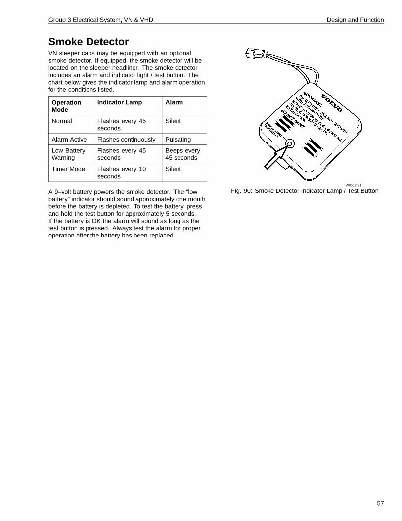
Smoke DetectorVN sleeper cabs may be equipped with an optionalsmoke detector. If equipped, the smoke detector will belocated on the sleeper headliner. The smoke detectorincludes an alarm and indicator light / test button. Thechart below gives the indicator lamp and alarm operationfor the conditions listed.
OperationMode
Indicator Lamp Alarm
Normal Flashes every 45seconds
Silent
Alarm Active Flashes continuously Pulsating
Low BatteryWarning
Flashes every 45seconds
Beeps every45 seconds
Timer Mode Flashes every 10seconds
Silent
A 9–volt battery powers the smoke detector. The “lowbattery” indicator should sound approximately one monthbefore the battery is depleted. To test the battery, pressand hold the test button for approximately 5 seconds.If the battery is OK the alarm will sound as long as thetest button is pressed. Always test the alarm for properoperation after the battery has been replaced.
W8002731
Fig. 90: Smoke Detector Indicator Lamp / Test Button
57
Group 3 Electrical System, VN & VHD Design and Function
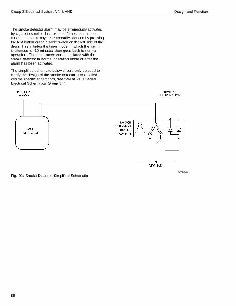
The smoke detector alarm may be erroneously activatedby cigarette smoke, dust, exhaust fumes, etc. In thesecases, the alarm may be temporarily silenced by pressingthe test button or the disable switch on the left side of thedash. This initiates the timer mode, in which the alarmis silenced for 10 minutes, then goes back to normaloperation. The timer mode can be initiated with thesmoke detector in normal operation mode or after thealarm has been activated.
The simplified schematic below should only be used toclarify the design of the smoke detector. For detailed,vehicle specific schematics, see “VN or VHD SeriesElectrical Schematics, Group 37.”
W3004348
Fig. 91: Smoke Detector, Simplified Schematic
58
Group 3 Electrical System, VN & VHD Design and Function
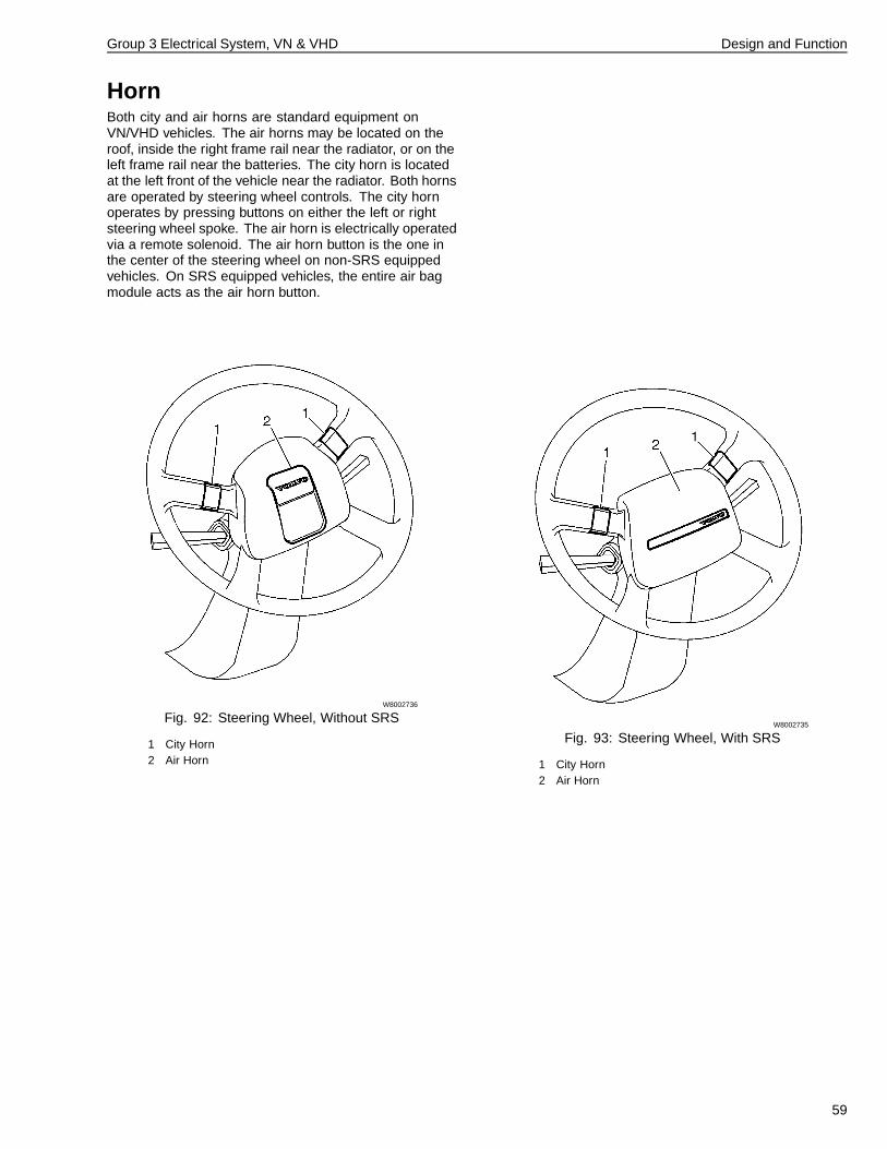
HornBoth city and air horns are standard equipment onVN/VHD vehicles. The air horns may be located on theroof, inside the right frame rail near the radiator, or on theleft frame rail near the batteries. The city horn is locatedat the left front of the vehicle near the radiator. Both hornsare operated by steering wheel controls. The city hornoperates by pressing buttons on either the left or rightsteering wheel spoke. The air horn is electrically operatedvia a remote solenoid. The air horn button is the one inthe center of the steering wheel on non-SRS equippedvehicles. On SRS equipped vehicles, the entire air bagmodule acts as the air horn button.
W8002736
Fig. 92: Steering Wheel, Without SRS
1 City Horn2 Air Horn
W8002735
Fig. 93: Steering Wheel, With SRS
1 City Horn2 Air Horn
59
Group 3 Electrical System, VN & VHD Design and Function
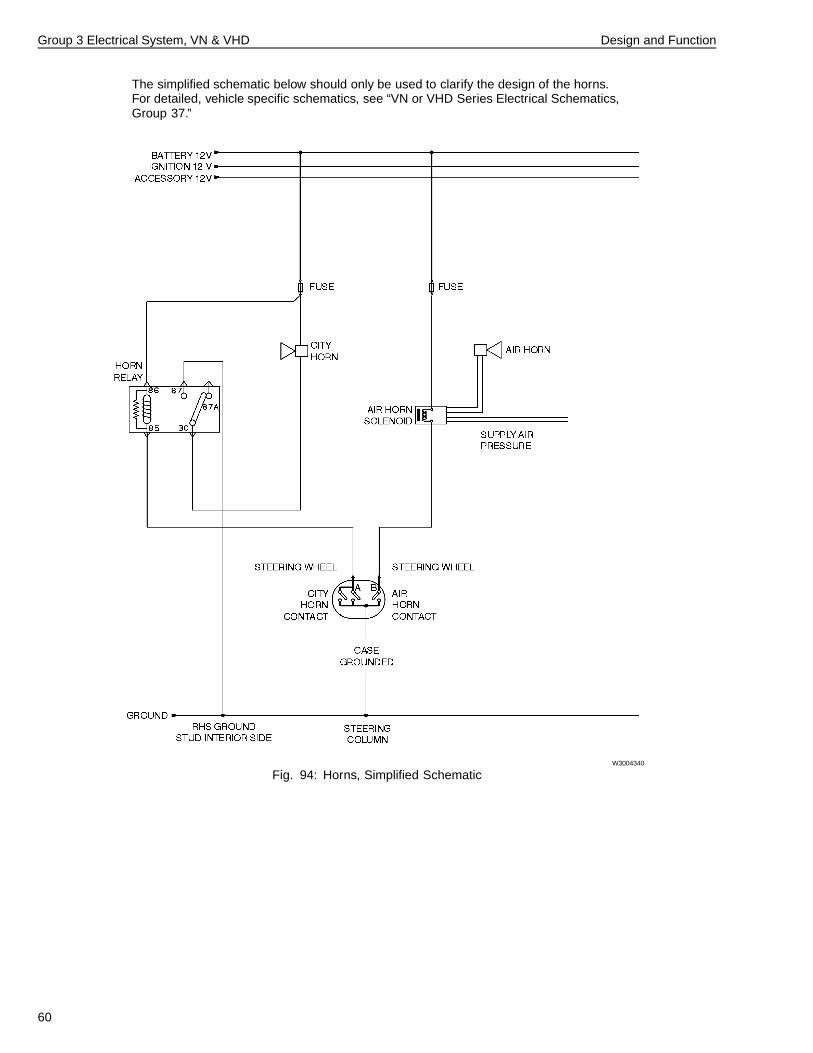
The simplified schematic below should only be used to clarify the design of the horns.For detailed, vehicle specific schematics, see “VN or VHD Series Electrical Schematics,Group 37.”
W3004340
Fig. 94: Horns, Simplified Schematic
60
Group 3 Electrical System, VN & VHD Design and Function
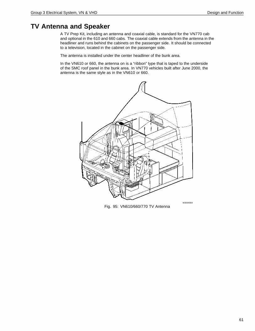
TV Antenna and SpeakerA TV Prep Kit, including an antenna and coaxial cable, is standard for the VN770 caband optional in the 610 and 660 cabs. The coaxial cable extends from the antenna in theheadliner and runs behind the cabinets on the passenger side. It should be connectedto a television, located in the cabinet on the passenger side.
The antenna is installed under the center headliner of the bunk area.
In the VN610 or 660, the antenna on is a “ribbon” type that is taped to the undersideof the SMC roof panel in the bunk area. In VN770 vehicles built after June 2000, theantenna is the same style as in the VN610 or 660.
W3004004
Fig. 95: VN610/660/770 TV Antenna
61
Group 3 Electrical System, VN & VHD Design and Function
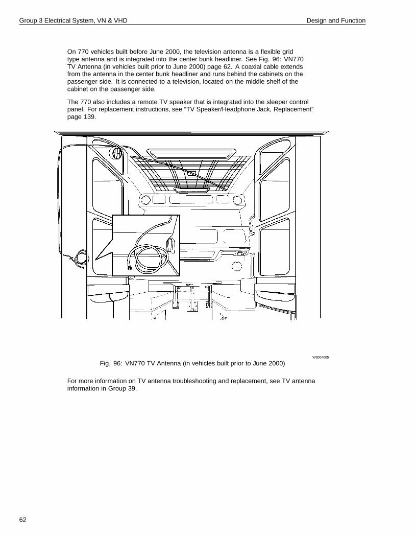
On 770 vehicles built before June 2000, the television antenna is a flexible gridtype antenna and is integrated into the center bunk headliner. See Fig. 96: VN770TV Antenna (in vehicles built prior to June 2000) page 62. A coaxial cable extendsfrom the antenna in the center bunk headliner and runs behind the cabinets on thepassenger side. It is connected to a television, located on the middle shelf of thecabinet on the passenger side.
The 770 also includes a remote TV speaker that is integrated into the sleeper controlpanel. For replacement instructions, see “TV Speaker/Headphone Jack, Replacement”page 139.
W3004005
Fig. 96: VN770 TV Antenna (in vehicles built prior to June 2000)
For more information on TV antenna troubleshooting and replacement, see TV antennainformation in Group 39.
62
Group 3 Electrical System, VN & VHD Design and Function
Bodybuilder Wiring
W3004424
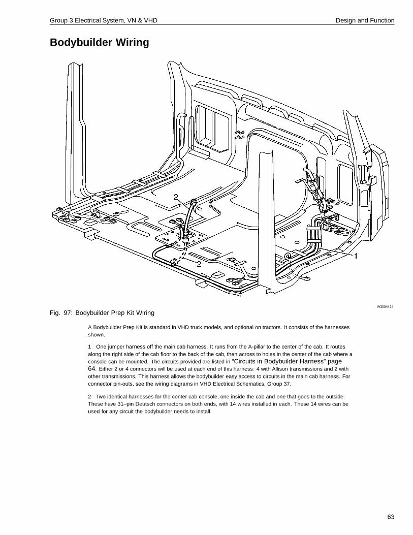
Fig. 97: Bodybuilder Prep Kit Wiring
A Bodybuilder Prep Kit is standard in VHD truck models, and optional on tractors. It consists of the harnessesshown.
1 One jumper harness off the main cab harness. It runs from the A-pillar to the center of the cab. It routesalong the right side of the cab floor to the back of the cab, then across to holes in the center of the cab where aconsole can be mounted. The circuits provided are listed in “Circuits in Bodybuilder Harness” page64. Either 2 or 4 connectors will be used at each end of this harness: 4 with Allison transmissions and 2 withother transmissions. This harness allows the bodybuilder easy access to circuits in the main cab harness. Forconnector pin-outs, see the wiring diagrams in VHD Electrical Schematics, Group 37.
2 Two identical harnesses for the center cab console, one inside the cab and one that goes to the outside.These have 31–pin Deutsch connectors on both ends, with 14 wires installed in each. These 14 wires can beused for any circuit the bodybuilder needs to install.
63
Group 3 Electrical System, VN & VHD Design and Function
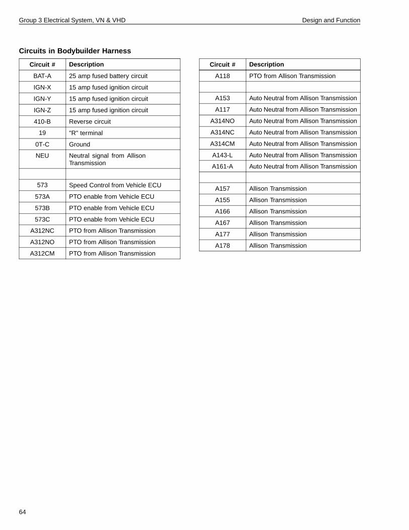
Circuits in Bodybuilder Harness
Circuit # Description
BAT-A 25 amp fused battery circuit
IGN-X 15 amp fused ignition circuit
IGN-Y 15 amp fused ignition circuit
IGN-Z 15 amp fused ignition circuit
410-B Reverse circuit
19 "R" terminal
0T-C Ground
NEU Neutral signal from AllisonTransmission
573 Speed Control from Vehicle ECU
573A PTO enable from Vehicle ECU
573B PTO enable from Vehicle ECU
573C PTO enable from Vehicle ECU
A312NC PTO from Allison Transmission
A312NO PTO from Allison Transmission
A312CM PTO from Allison Transmission
Circuit # Description
A118 PTO from Allison Transmission
A153 Auto Neutral from Allison Transmission
A117 Auto Neutral from Allison Transmission
A314NO Auto Neutral from Allison Transmission
A314NC Auto Neutral from Allison Transmission
A314CM Auto Neutral from Allison Transmission
A143-L Auto Neutral from Allison Transmission
A161-A Auto Neutral from Allison Transmission
A157 Allison Transmission
A155 Allison Transmission
A166 Allison Transmission
A167 Allison Transmission
A177 Allison Transmission
A178 Allison Transmission
64
Group 3 Electrical System, VN & VHD Design and Function
Bodybuilder Lighting Junction Box
W3004413
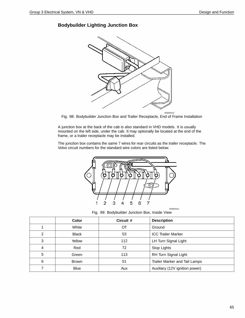
Fig. 98: Bodybuilder Junction Box and Trailer Receptacle, End of Frame Installation
A junction box at the back of the cab is also standard in VHD models. It is usuallymounted on the left side, under the cab. It may optionally be located at the end of theframe, or a trailer receptacle may be installed.
The junction box contains the same 7 wires for rear circuits as the trailer receptacle. TheVolvo circuit numbers for the standard wire colors are listed below.
W3004412
Fig. 99: Bodybuilder Junction Box, Inside View
Color Circuit # Description
1 White OT Ground
2 Black 53 ICC Trailer Marker
3 Yellow 112 LH Turn Signal Light
4 Red 72 Stop Lights
5 Green 113 RH Turn Signal Light
6 Brown 51 Trailer Marker and Tail Lamps
7 Blue Aux Auxiliary (12V ignition power)
65
Group 3 Electrical System, VN & VHD Design and Function
Bodybuilder Option Connectors
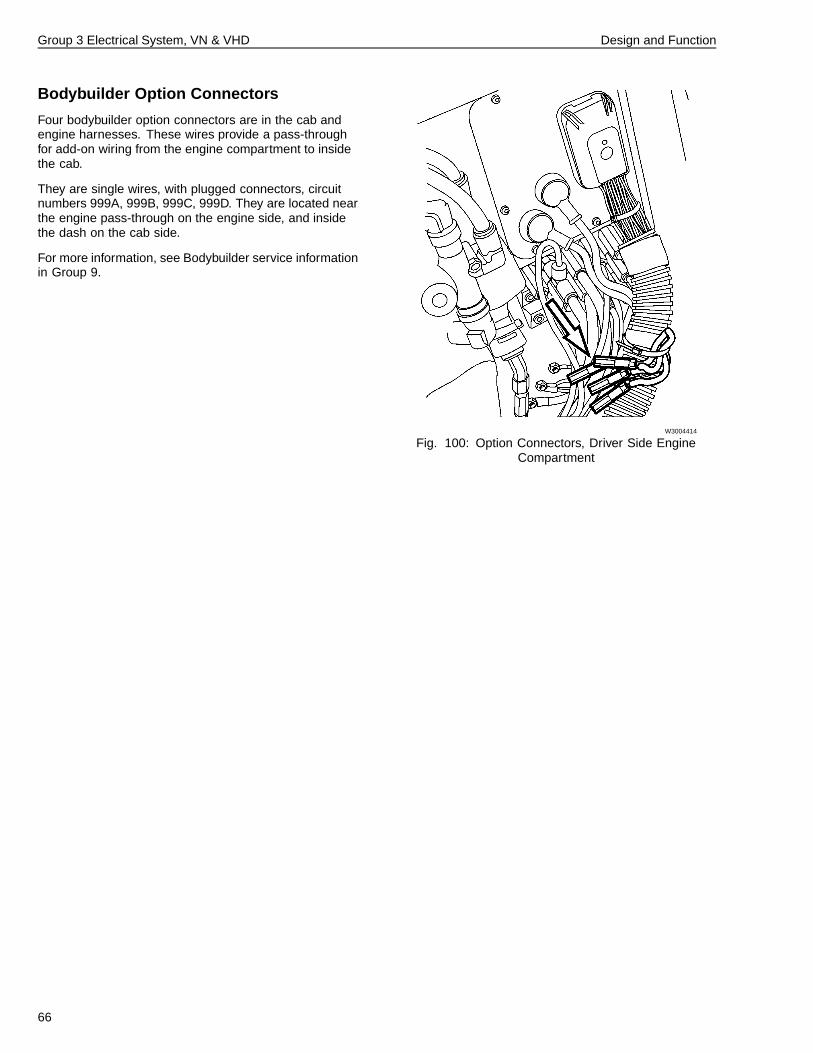
Four bodybuilder option connectors are in the cab andengine harnesses. These wires provide a pass-throughfor add-on wiring from the engine compartment to insidethe cab.
They are single wires, with plugged connectors, circuitnumbers 999A, 999B, 999C, 999D. They are located nearthe engine pass-through on the engine side, and insidethe dash on the cab side.
For more information, see Bodybuilder service informationin Group 9.
W3004414
Fig. 100: Option Connectors, Driver Side EngineCompartment
66
Group 3 Electrical System, VN & VHD Troubleshooting
Troubleshooting
Electrical System Troubleshooting• “Troubleshooting Using a Digital Multimeter” page 67
• “Troubleshooting Wiring and Connectors” page 68
• “Switch Troubleshooting” page 77
• “Electronic Control Unit (ECU) Troubleshooting” page77
Electrical System
Troubleshooting Using a Digital
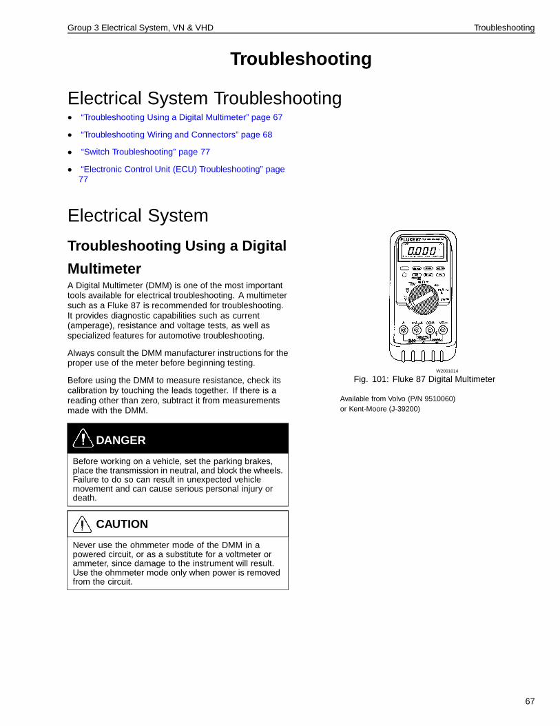
MultimeterA Digital Multimeter (DMM) is one of the most importanttools available for electrical troubleshooting. A multimetersuch as a Fluke 87 is recommended for troubleshooting.It provides diagnostic capabilities such as current(amperage), resistance and voltage tests, as well asspecialized features for automotive troubleshooting.
Always consult the DMM manufacturer instructions for theproper use of the meter before beginning testing.
Before using the DMM to measure resistance, check itscalibration by touching the leads together. If there is areading other than zero, subtract it from measurementsmade with the DMM.
DANGER
Before working on a vehicle, set the parking brakes,place the transmission in neutral, and block the wheels.Failure to do so can result in unexpected vehiclemovement and can cause serious personal injury ordeath.
CAUTION
Never use the ohmmeter mode of the DMM in apowered circuit, or as a substitute for a voltmeter orammeter, since damage to the instrument will result.Use the ohmmeter mode only when power is removedfrom the circuit.
W2001014
Fig. 101: Fluke 87 Digital Multimeter
Available from Volvo (P/N 9510060)or Kent-Moore (J-39200)
67
Group 3 Electrical System, VN & VHD Troubleshooting
Troubleshooting Wiring and ConnectorsGeneral Troubleshooting ProceduresGeneral Troubleshooting +Procedures
• Use Multimeter J-39200 (or equivalent tool) to performtests. The use of test lights is discouraged.
• When troubleshooting wiring and connectors usebreakout boxes/harnesses when available. A listof various breakout boxes/harnesses is included in“Special Tools” page 7.
• Never pierce the wiring insulation with test probes.
• Do not pierce through seals on water-resistantconnectors.
• Never insert test probes into connectors. The probesmay spread the terminals and cause intermittent faults.
• If breakout boxes/harnesses are not available, contactthe metal outer edges of connector terminals asnecessary to take readings.
• Consult “VN or VHD Series Electrical Schematics” inGroup 37 for vehicle specific wiring and connectorinformation. These schematics include pin-out andvehicle location drawings for connectors.
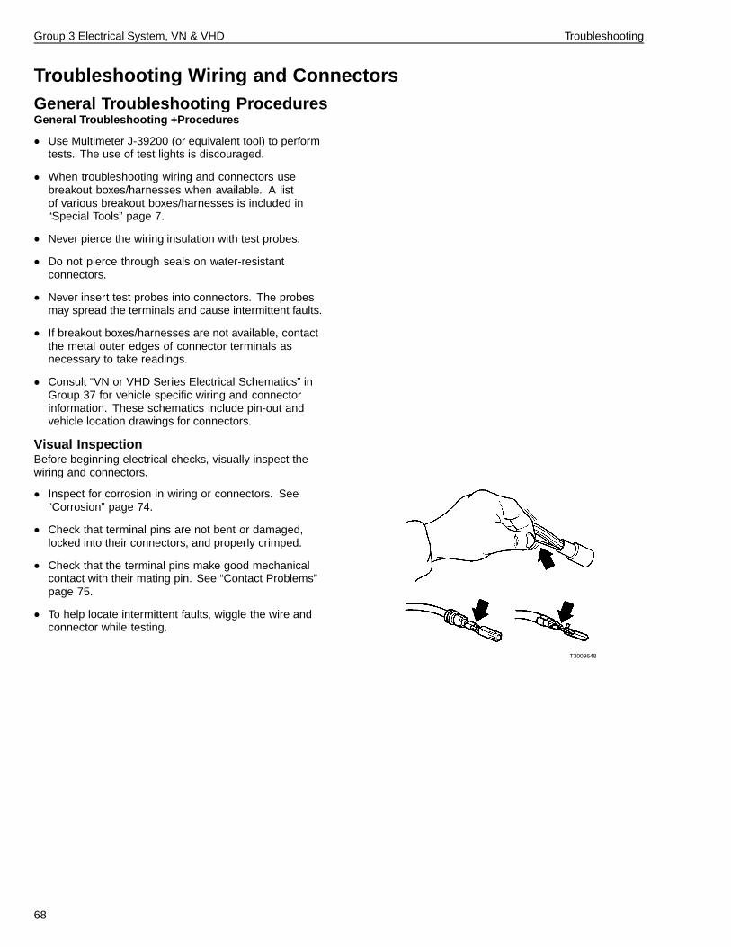
Visual InspectionBefore beginning electrical checks, visually inspect thewiring and connectors.
• Inspect for corrosion in wiring or connectors. See“Corrosion” page 74.
• Check that terminal pins are not bent or damaged,locked into their connectors, and properly crimped.
• Check that the terminal pins make good mechanicalcontact with their mating pin. See “Contact Problems”page 75.
• To help locate intermittent faults, wiggle the wire andconnector while testing.
T3009648
68
Group 3 Electrical System, VN & VHD Troubleshooting
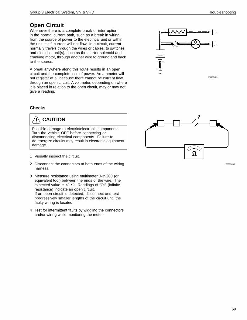
Open CircuitWhenever there is a complete break or interruptionin the normal current path, such as a break in wiringfrom the source of power to the electrical unit or withinthe unit itself, current will not flow. In a circuit, currentnormally travels through the wires or cables, to switchesand electrical unit(s), such as the starter solenoid andcranking motor, through another wire to ground and backto the source.
A break anywhere along this route results in an opencircuit and the complete loss of power. An ammeter willnot register at all because there cannot be current flowthrough an open circuit. A voltmeter, depending on whereit is placed in relation to the open circuit, may or may notgive a reading.
W3000489
Checks
CAUTION
Possible damage to electric/electronic components.Turn the vehicle OFF before connecting ordisconnecting electrical components. Failure tode-energize circuits may result in electronic equipmentdamage.
1 Visually inspect the circuit.
2 Disconnect the connectors at both ends of the wiringharness.
3 Measure resistance using multimeter J-39200 (orequivalent tool) between the ends of the wire. Theexpected value is <1 . Readings of “OL” (infiniteresistance) indicate an open circuit.If an open circuit is detected, disconnect and testprogressively smaller lengths of the circuit until thefaulty wiring is located.
4 Test for intermittent faults by wiggling the connectorsand/or wiring while monitoring the meter.
T3009650
69
Group 3 Electrical System, VN & VHD Troubleshooting
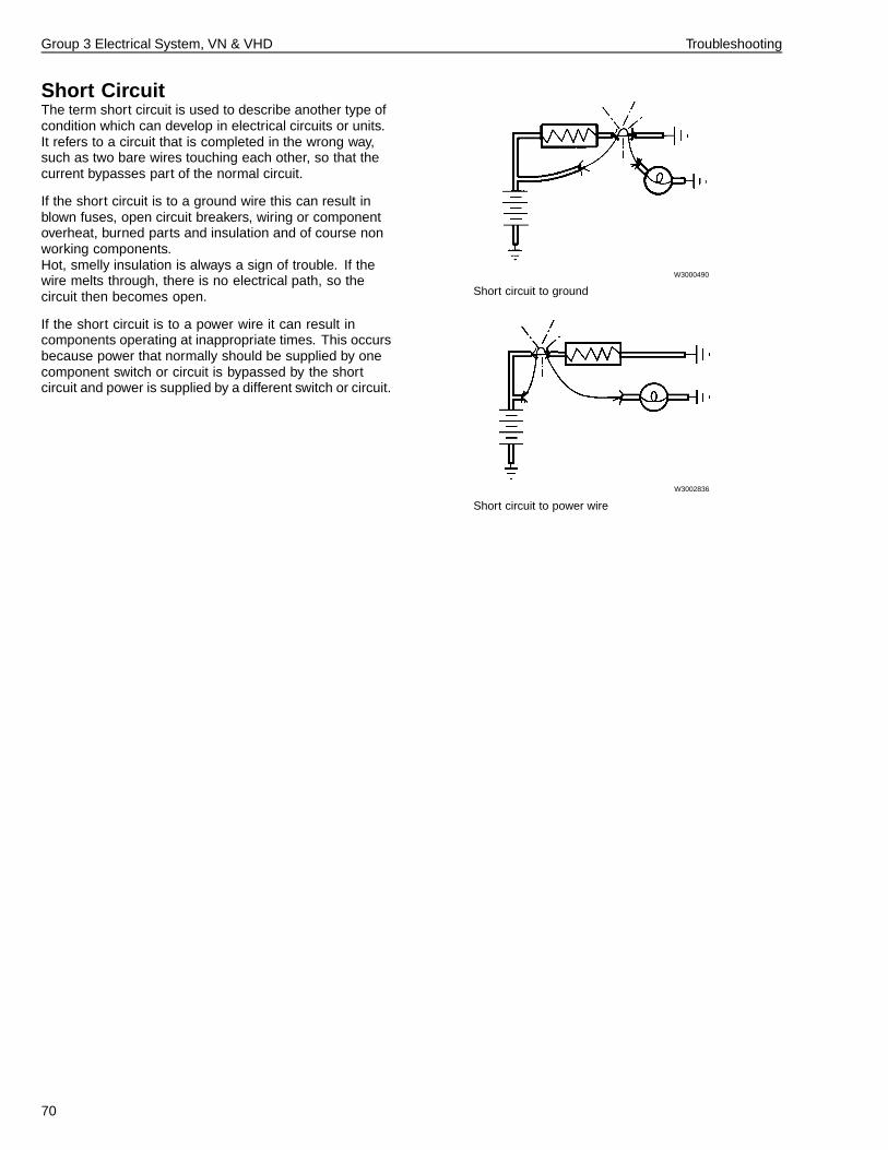
Short CircuitThe term short circuit is used to describe another type ofcondition which can develop in electrical circuits or units.It refers to a circuit that is completed in the wrong way,such as two bare wires touching each other, so that thecurrent bypasses part of the normal circuit.
If the short circuit is to a ground wire this can result inblown fuses, open circuit breakers, wiring or componentoverheat, burned parts and insulation and of course nonworking components.Hot, smelly insulation is always a sign of trouble. If thewire melts through, there is no electrical path, so thecircuit then becomes open.
If the short circuit is to a power wire it can result incomponents operating at inappropriate times. This occursbecause power that normally should be supplied by onecomponent switch or circuit is bypassed by the shortcircuit and power is supplied by a different switch or circuit.
W3000490
Short circuit to ground
W3002836
Short circuit to power wire
70
Group 3 Electrical System, VN & VHD Troubleshooting
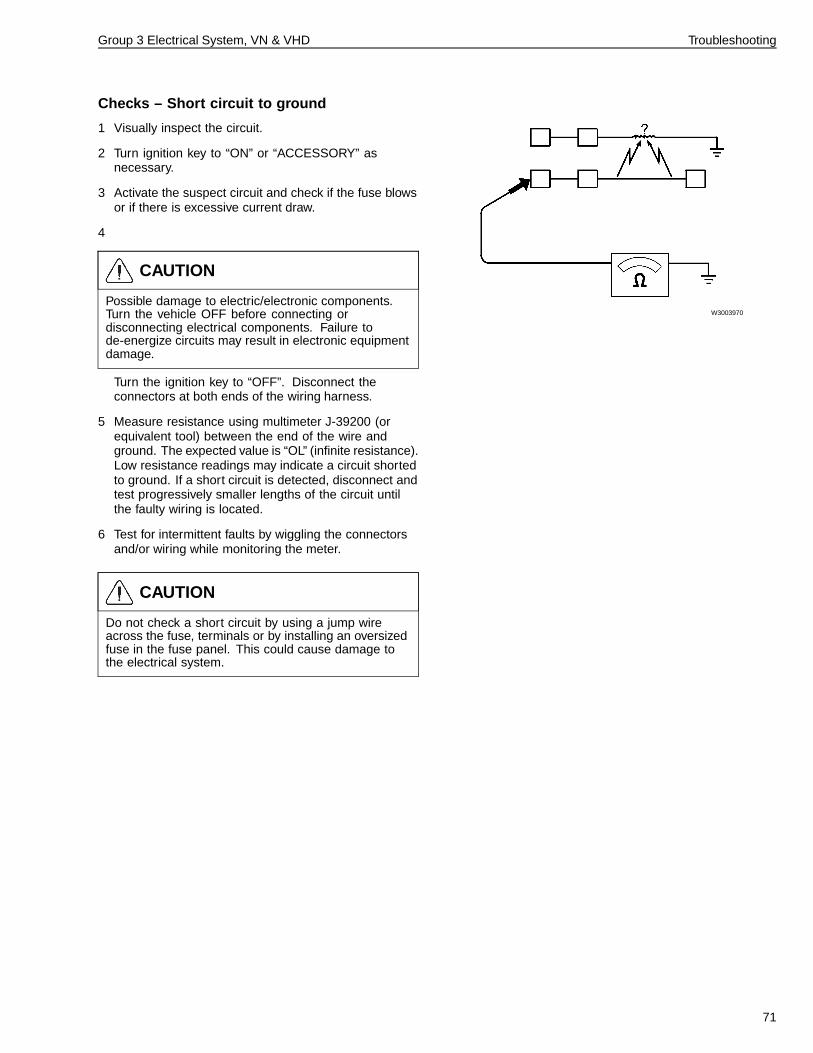
Checks – Short circuit to ground
1 Visually inspect the circuit.
2 Turn ignition key to “ON” or “ACCESSORY” asnecessary.
3 Activate the suspect circuit and check if the fuse blowsor if there is excessive current draw.
4
CAUTION
Possible damage to electric/electronic components.Turn the vehicle OFF before connecting ordisconnecting electrical components. Failure tode-energize circuits may result in electronic equipmentdamage.
Turn the ignition key to “OFF”. Disconnect theconnectors at both ends of the wiring harness.
5 Measure resistance using multimeter J-39200 (orequivalent tool) between the end of the wire andground. The expected value is “OL” (infinite resistance).Low resistance readings may indicate a circuit shortedto ground. If a short circuit is detected, disconnect andtest progressively smaller lengths of the circuit untilthe faulty wiring is located.
6 Test for intermittent faults by wiggling the connectorsand/or wiring while monitoring the meter.
CAUTION
Do not check a short circuit by using a jump wireacross the fuse, terminals or by installing an oversizedfuse in the fuse panel. This could cause damage tothe electrical system.
W3003970
71
Group 3 Electrical System, VN & VHD Troubleshooting
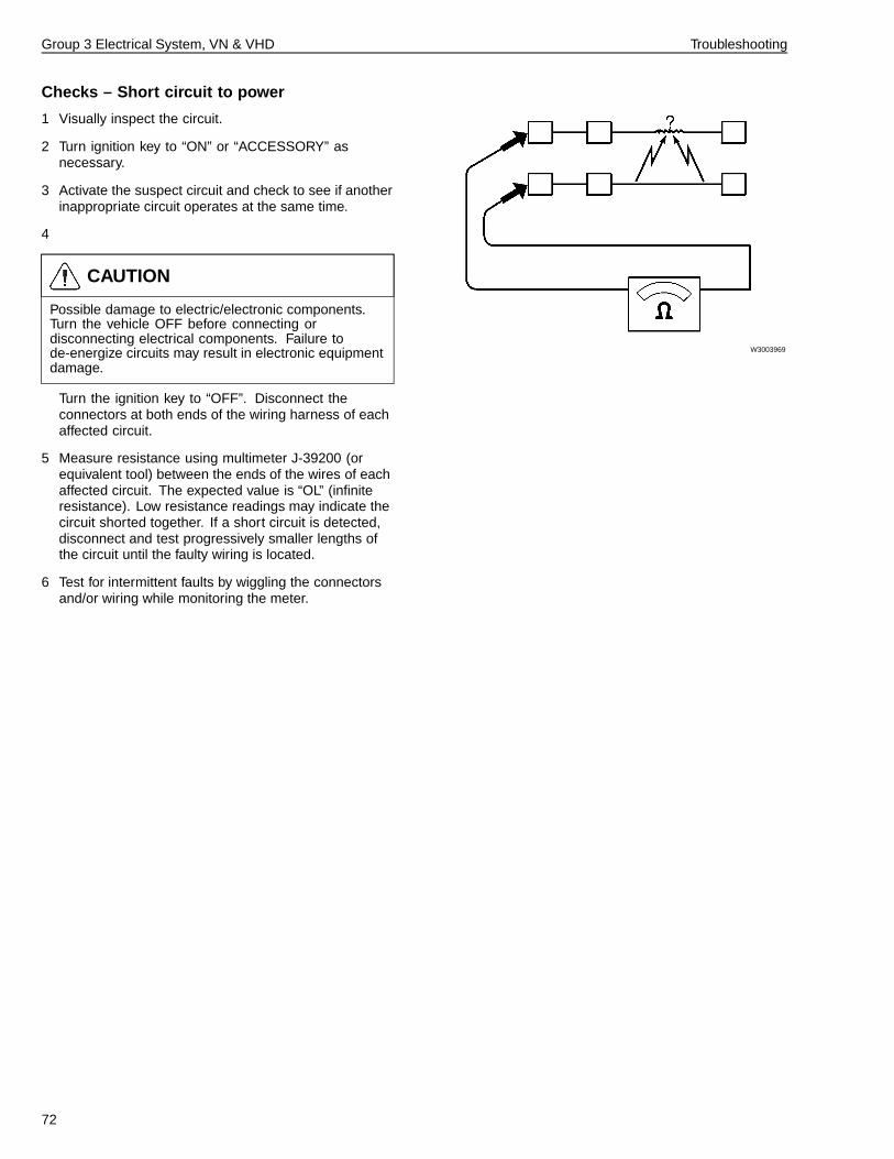
Checks – Short circuit to power
1 Visually inspect the circuit.
2 Turn ignition key to “ON” or “ACCESSORY” asnecessary.
3 Activate the suspect circuit and check to see if anotherinappropriate circuit operates at the same time.
4
CAUTION
Possible damage to electric/electronic components.Turn the vehicle OFF before connecting ordisconnecting electrical components. Failure tode-energize circuits may result in electronic equipmentdamage.
Turn the ignition key to “OFF”. Disconnect theconnectors at both ends of the wiring harness of eachaffected circuit.
5 Measure resistance using multimeter J-39200 (orequivalent tool) between the ends of the wires of eachaffected circuit. The expected value is “OL” (infiniteresistance). Low resistance readings may indicate thecircuit shorted together. If a short circuit is detected,disconnect and test progressively smaller lengths ofthe circuit until the faulty wiring is located.
6 Test for intermittent faults by wiggling the connectorsand/or wiring while monitoring the meter.
W3003969
72
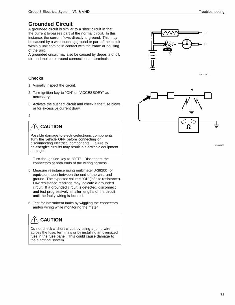
Group 3 Electrical System, VN & VHD Troubleshooting
Grounded CircuitA grounded circuit is similar to a short circuit in thatthe current bypasses part of the normal circuit. In thisinstance, the current flows directly to ground. This maybe caused by a wire touching ground or part of the circuitwithin a unit coming in contact with the frame or housingof the unit.A grounded circuit may also be caused by deposits of oil,dirt and moisture around connections or terminals.
W3000491
Checks
1 Visually inspect the circuit.
2 Turn ignition key to “ON” or “ACCESSORY” asnecessary.
3 Activate the suspect circuit and check if the fuse blowsor for excessive current draw.
4
CAUTION
Possible damage to electric/electronic components.Turn the vehicle OFF before connecting ordisconnecting electrical components. Failure tode-energize circuits may result in electronic equipmentdamage.
Turn the ignition key to “OFF”. Disconnect theconnectors at both ends of the wiring harness.
5 Measure resistance using multimeter J-39200 (orequivalent tool) between the end of the wire andground. The expected value is “OL” (infinite resistance).Low resistance readings may indicate a groundedcircuit. If a grounded circuit is detected, disconnectand test progressively smaller lengths of the circuituntil the faulty wiring is located.
6 Test for intermittent faults by wiggling the connectorsand/or wiring while monitoring the meter.
CAUTION
Do not check a short circuit by using a jump wireacross the fuse, terminals or by installing an oversizedfuse in the fuse panel. This could cause damage tothe electrical system.
W3003968
73
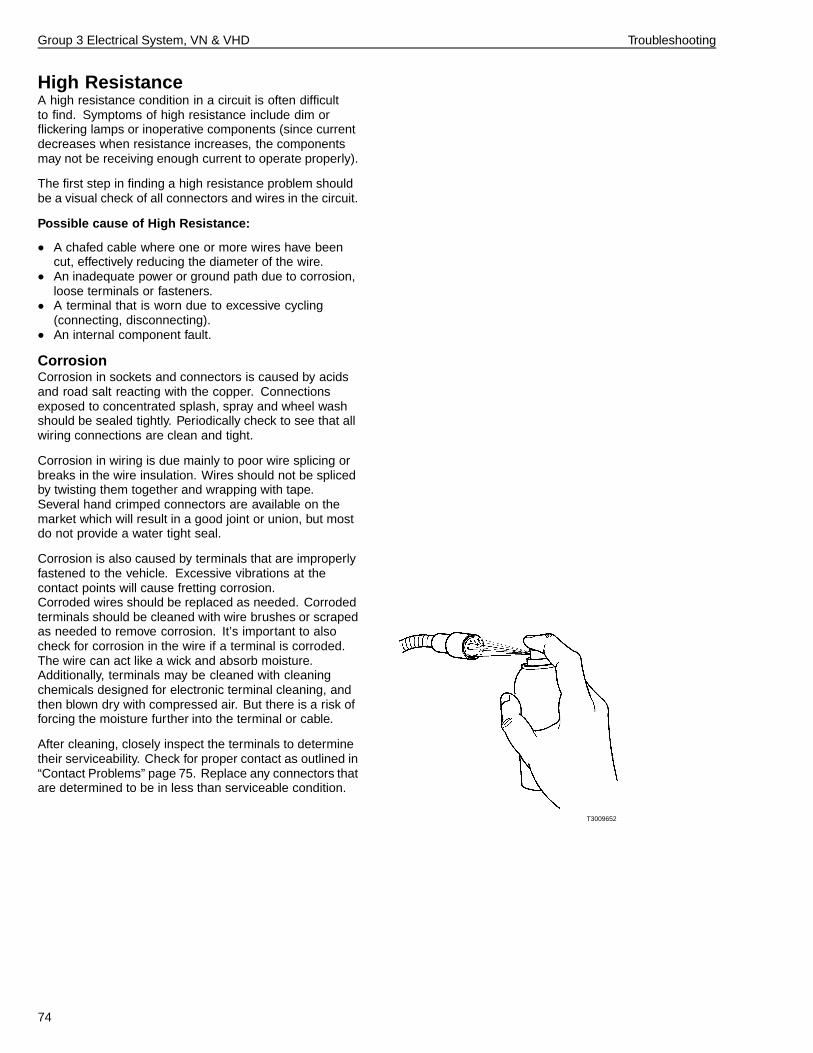
Group 3 Electrical System, VN & VHD Troubleshooting
High ResistanceA high resistance condition in a circuit is often difficultto find. Symptoms of high resistance include dim orflickering lamps or inoperative components (since currentdecreases when resistance increases, the componentsmay not be receiving enough current to operate properly).
The first step in finding a high resistance problem shouldbe a visual check of all connectors and wires in the circuit.
Possible cause of High Resistance:
• A chafed cable where one or more wires have beencut, effectively reducing the diameter of the wire.
• An inadequate power or ground path due to corrosion,loose terminals or fasteners.
• A terminal that is worn due to excessive cycling(connecting, disconnecting).
• An internal component fault.
CorrosionCorrosion in sockets and connectors is caused by acidsand road salt reacting with the copper. Connectionsexposed to concentrated splash, spray and wheel washshould be sealed tightly. Periodically check to see that allwiring connections are clean and tight.
Corrosion in wiring is due mainly to poor wire splicing orbreaks in the wire insulation. Wires should not be splicedby twisting them together and wrapping with tape.Several hand crimped connectors are available on themarket which will result in a good joint or union, but mostdo not provide a water tight seal.
Corrosion is also caused by terminals that are improperlyfastened to the vehicle. Excessive vibrations at thecontact points will cause fretting corrosion.Corroded wires should be replaced as needed. Corrodedterminals should be cleaned with wire brushes or scrapedas needed to remove corrosion. It’s important to alsocheck for corrosion in the wire if a terminal is corroded.The wire can act like a wick and absorb moisture.Additionally, terminals may be cleaned with cleaningchemicals designed for electronic terminal cleaning, andthen blown dry with compressed air. But there is a risk offorcing the moisture further into the terminal or cable.
After cleaning, closely inspect the terminals to determinetheir serviceability. Check for proper contact as outlined in“Contact Problems” page 75. Replace any connectors thatare determined to be in less than serviceable condition.
T3009652
74
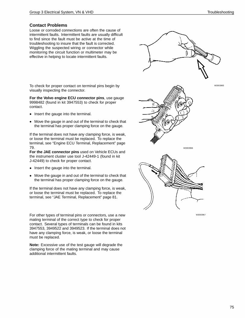
Group 3 Electrical System, VN & VHD Troubleshooting
Contact ProblemsLoose or corroded connections are often the cause ofintermittent faults. Intermittent faults are usually difficultto find since the fault must be active at the time oftroubleshooting to insure that the fault is corrected.Wiggling the suspected wiring or connector whilemonitoring the circuit function or multimeter may beeffective in helping to locate intermittent faults.
W3003965To check for proper contact on terminal pins begin byvisually inspecting the connector.
For the Volvo engine ECU connector pins , use gauge9998482 (found in kit 3947553) to check for propercontact.
• Insert the gauge into the terminal.
• Move the gauge in and out of the terminal to check thatthe terminal has proper clamping force on the gauge.
If the terminal does not have any clamping force, is weak,or loose the terminal must be replaced. To replace theterminal, see “Engine ECU Terminal, Replacement” page79. W3003966
For the JAE connector pins used on Vehicle ECUs andthe instrument cluster use tool J-42449-1 (found in kitJ-42449) to check for proper contact.
• Insert the gauge into the terminal.
• Move the gauge in and out of the terminal to check thatthe terminal has proper clamping force on the gauge.
If the terminal does not have any clamping force, is weak,or loose the terminal must be replaced. To replace theterminal, see “JAE Terminal, Replacement” page 81.
W3003967For other types of terminal pins or connectors, use a newmating terminal of the correct type to check for propercontact. Several types of terminals can be found in kits3947553, 3949522 and 3949523. If the terminal does nothave any clamping force, is weak, or loose the terminalmust be replaced.
Note: Excessive use of the test gauge will degrade theclamping force of the mating terminal and may causeadditional intermittent faults.
75
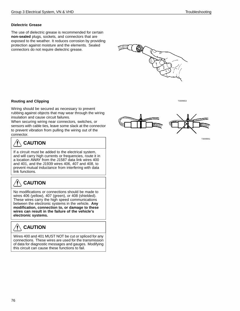
Group 3 Electrical System, VN & VHD Troubleshooting
Dielectric Grease
The use of dielectric grease is recommended for certainnon-sealed plugs, sockets, and connectors that areexposed to the weather. It reduces corrosion by providingprotection against moisture and the elements. Sealedconnectors do not require dielectric grease.
T3009653Routing and Clipping
Wiring should be secured as necessary to preventrubbing against objects that may wear through the wiringinsulation and cause circuit failures.When securing wiring near connectors, switches, orsensors with cable ties, leave some slack at the connectorto prevent vibration from pulling the wiring out of theconnector.
T3009651
CAUTION
If a circuit must be added to the electrical system,and will carry high currents or frequencies, route it ina location AWAY from the J1587 data link wires 400and 401, and the J1939 wires 406, 407 and 408, toprevent mutual inductance from interfering with datalink functions.
CAUTION
No modifications or connections should be made towires 406 (yellow), 407 (green), or 408 (shielded).These wires carry the high speed communicationsbetween the electronic systems in the vehicle. Anymodification, connection to, or damage to thesewires can result in the failure of the vehicle’selectronic systems.
CAUTION
Wires 400 and 401 MUST NOT be cut or spliced for anyconnections. These wires are used for the transmissionof data for diagnostic messages and gauges. Modifyingthis circuit can cause these functions to fail.
76
Group 3 Electrical System, VN & VHD Troubleshooting
Switch TroubleshootingChecking the continuity between pin or cavity positionsin various operating positions may help troubleshootswitches. The switch detail information in “Switch LogicDiagrams” page 37 or in the electrical schematics maybe used as a guide when checking for proper switchoperation.
Troubleshooting information on specific switches may alsobe found in various service information that deals withspecific components or systems.
Electronic Control Unit (ECU) TroubleshootingGenerally there is no actual testing of electronic controlunits or electronic modules. Electronic control unit/moduleconnector wire input or output may be tested, but cautionmust be used not to introduce problems where noneexist. Simple troubleshooting of such things as powerand ground supply or sensor continuity may be attemptedwith the ECU disconnected.
If tests exist for an ECU, the details of those tests will becovered in the service procedures for that ECU.
77

78
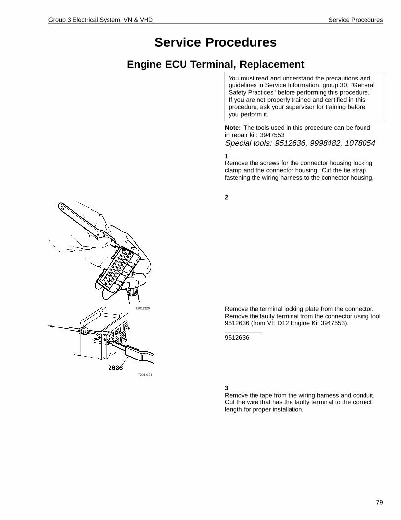
Group 3 Electrical System, VN & VHD Service Procedures
Service Procedures
Engine ECU Terminal, ReplacementYou must read and understand the precautions andguidelines in Service Information, group 30, "GeneralSafety Practices" before performing this procedure.If you are not properly trained and certified in thisprocedure, ask your supervisor for training beforeyou perform it.
Note: The tools used in this procedure can be foundin repair kit: 3947553Special tools: 9512636, 9998482, 1078054
1Remove the screws for the connector housing lockingclamp and the connector housing. Cut the tie strapfastening the wiring harness to the connector housing.
2
T2012120
T2012121
Remove the terminal locking plate from the connector.Remove the faulty terminal from the connector using tool9512636 (from VE D12 Engine Kit 3947553).
9512636
3Remove the tape from the wiring harness and conduit.Cut the wire that has the faulty terminal to the correctlength for proper installation.
79
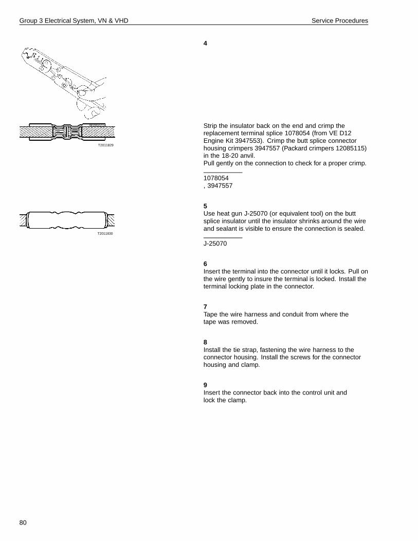
Group 3 Electrical System, VN & VHD Service Procedures
4
W2002217
T2011829
Strip the insulator back on the end and crimp thereplacement terminal splice 1078054 (from VE D12Engine Kit 3947553). Crimp the butt splice connectorhousing crimpers 3947557 (Packard crimpers 12085115)in the 18-20 anvil.Pull gently on the connection to check for a proper crimp.
1078054, 3947557
5
T2011830
Use heat gun J-25070 (or equivalent tool) on the buttsplice insulator until the insulator shrinks around the wireand sealant is visible to ensure the connection is sealed.
J-25070
6Insert the terminal into the connector until it locks. Pull onthe wire gently to insure the terminal is locked. Install theterminal locking plate in the connector.
7Tape the wire harness and conduit from where thetape was removed.
8Install the tie strap, fastening the wire harness to theconnector housing. Install the screws for the connectorhousing and clamp.
9Insert the connector back into the control unit andlock the clamp.
80
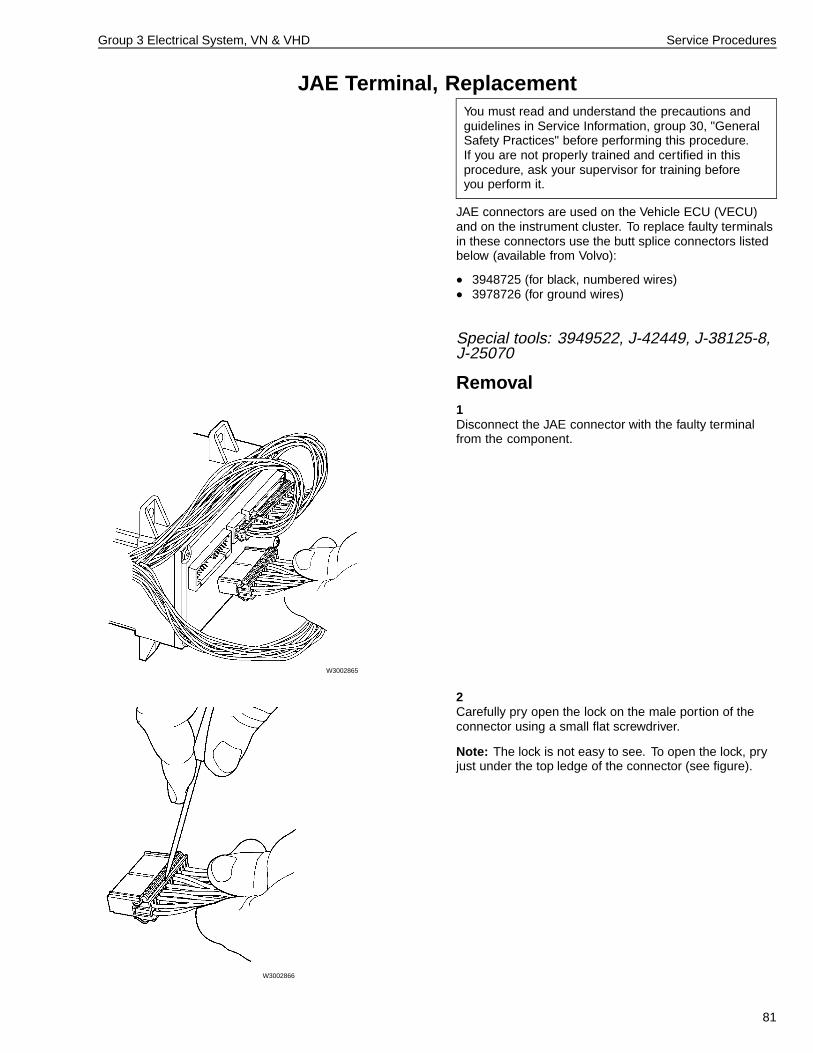
Group 3 Electrical System, VN & VHD Service Procedures
JAE Terminal, ReplacementYou must read and understand the precautions andguidelines in Service Information, group 30, "GeneralSafety Practices" before performing this procedure.If you are not properly trained and certified in thisprocedure, ask your supervisor for training beforeyou perform it.
JAE connectors are used on the Vehicle ECU (VECU)and on the instrument cluster. To replace faulty terminalsin these connectors use the butt splice connectors listedbelow (available from Volvo):
• 3948725 (for black, numbered wires)• 3978726 (for ground wires)
Special tools: 3949522, J-42449, J-38125-8,J-25070
Removal1
W3002865
Disconnect the JAE connector with the faulty terminalfrom the component.
2
W3002866
Carefully pry open the lock on the male portion of theconnector using a small flat screwdriver.
Note: The lock is not easy to see. To open the lock, pryjust under the top ledge of the connector (see figure).
81
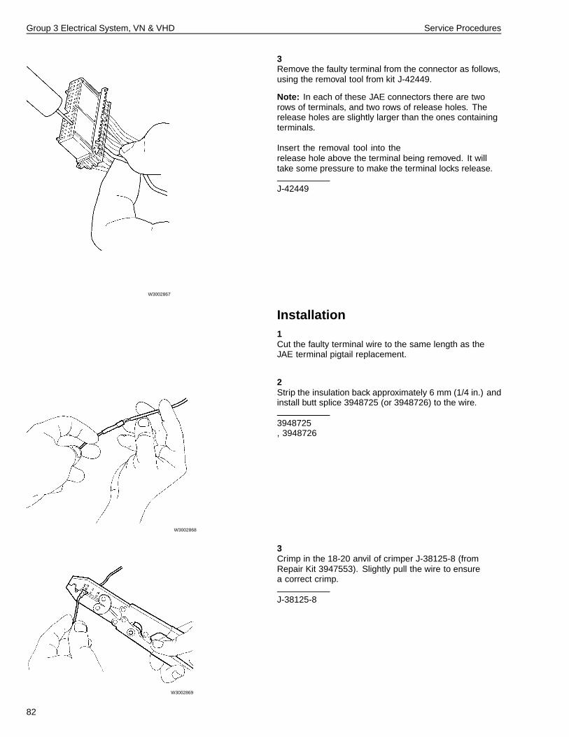
Group 3 Electrical System, VN & VHD Service Procedures
3
W3002867
Remove the faulty terminal from the connector as follows,using the removal tool from kit J-42449.
Note: In each of these JAE connectors there are tworows of terminals, and two rows of release holes. Therelease holes are slightly larger than the ones containingterminals.
Insert the removal tool into therelease hole above the terminal being removed. It willtake some pressure to make the terminal locks release.
J-42449
Installation1Cut the faulty terminal wire to the same length as theJAE terminal pigtail replacement.
2
W3002868
Strip the insulation back approximately 6 mm (1/4 in.) andinstall butt splice 3948725 (or 3948726) to the wire.
3948725, 3948726
3
W3002869
Crimp in the 18-20 anvil of crimper J-38125-8 (fromRepair Kit 3947553). Slightly pull the wire to ensurea correct crimp.
J-38125-8
82
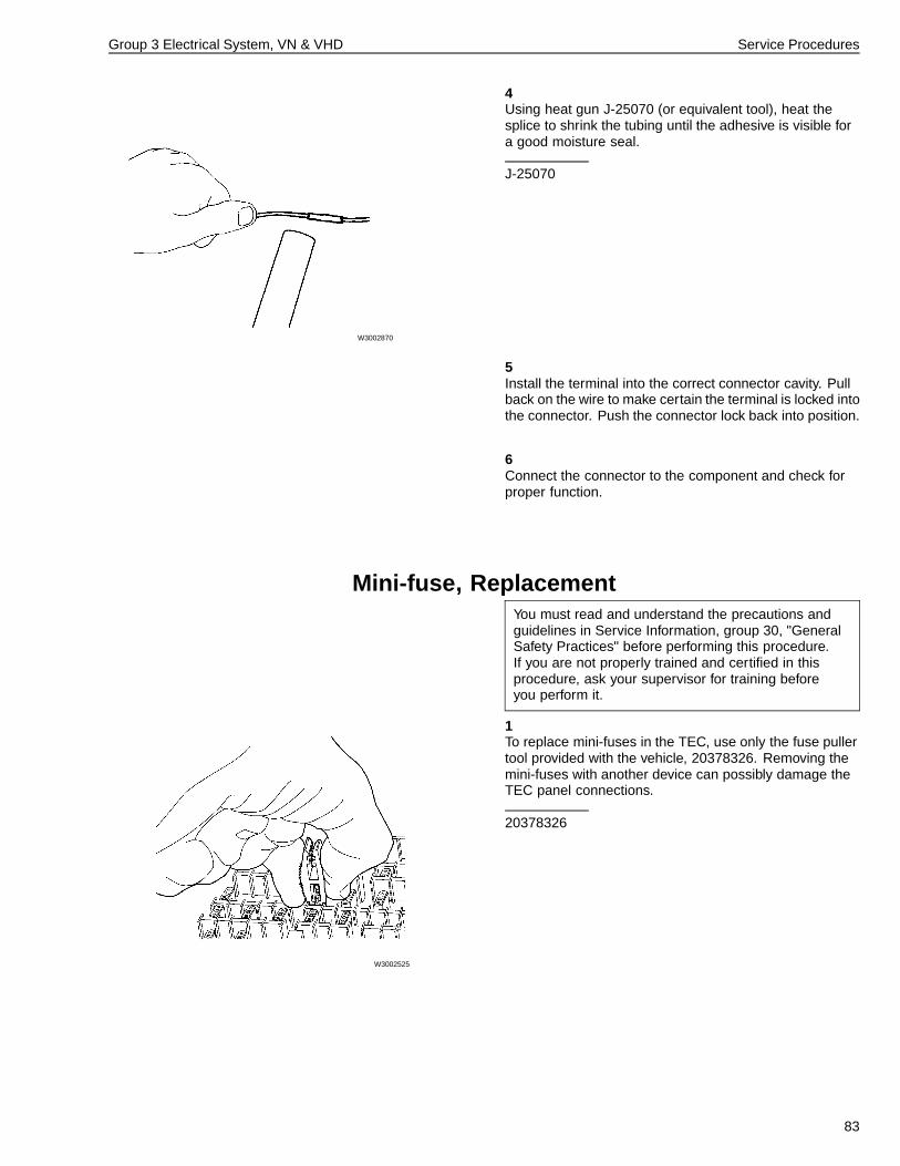
Group 3 Electrical System, VN & VHD Service Procedures
4
W3002870
Using heat gun J-25070 (or equivalent tool), heat thesplice to shrink the tubing until the adhesive is visible fora good moisture seal.
J-25070
5Install the terminal into the correct connector cavity. Pullback on the wire to make certain the terminal is locked intothe connector. Push the connector lock back into position.
6Connect the connector to the component and check forproper function.
Mini-fuse, ReplacementYou must read and understand the precautions andguidelines in Service Information, group 30, "GeneralSafety Practices" before performing this procedure.If you are not properly trained and certified in thisprocedure, ask your supervisor for training beforeyou perform it.
1
W3002525
To replace mini-fuses in the TEC, use only the fuse pullertool provided with the vehicle, 20378326. Removing themini-fuses with another device can possibly damage theTEC panel connections.
20378326
83
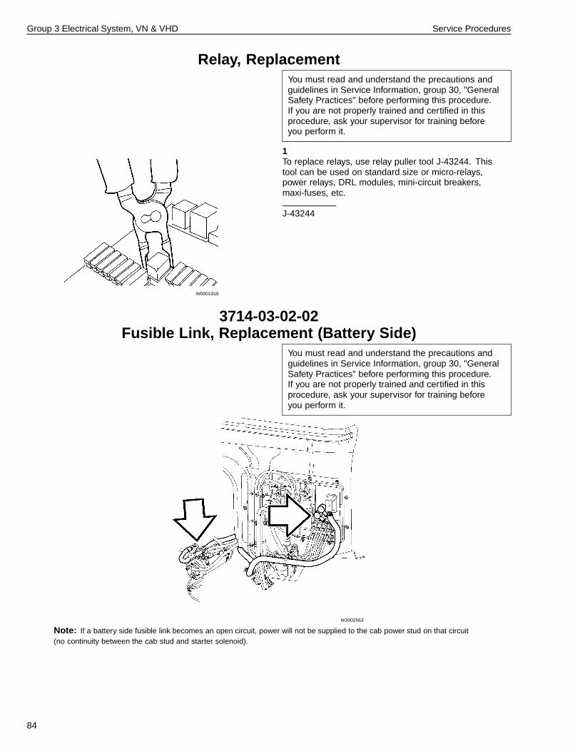
Group 3 Electrical System, VN & VHD Service Procedures
Relay, ReplacementYou must read and understand the precautions andguidelines in Service Information, group 30, "GeneralSafety Practices" before performing this procedure.If you are not properly trained and certified in thisprocedure, ask your supervisor for training beforeyou perform it.
1
W0001918
To replace relays, use relay puller tool J-43244. Thistool can be used on standard size or micro-relays,power relays, DRL modules, mini-circuit breakers,maxi-fuses, etc.
J-43244
3714-03-02-02Fusible Link, Replacement (Battery Side)
You must read and understand the precautions andguidelines in Service Information, group 30, "GeneralSafety Practices" before performing this procedure.If you are not properly trained and certified in thisprocedure, ask your supervisor for training beforeyou perform it.
W3002563
Note: If a battery side fusible link becomes an open circuit, power will not be supplied to the cab power stud on that circuit(no continuity between the cab stud and starter solenoid).
84
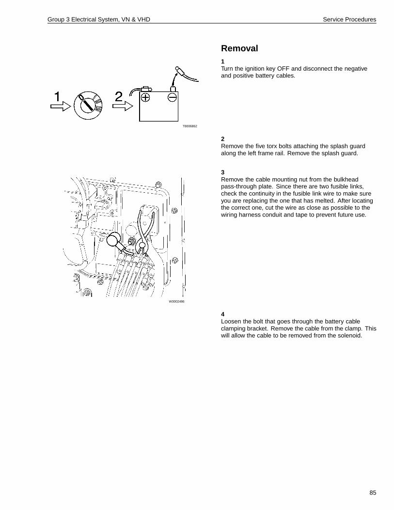
Group 3 Electrical System, VN & VHD Service Procedures
Removal1
T8006862
Turn the ignition key OFF and disconnect the negativeand positive battery cables.
2Remove the five torx bolts attaching the splash guardalong the left frame rail. Remove the splash guard.
3
W3002486
Remove the cable mounting nut from the bulkheadpass-through plate. Since there are two fusible links,check the continuity in the fusible link wire to make sureyou are replacing the one that has melted. After locatingthe correct one, cut the wire as close as possible to thewiring harness conduit and tape to prevent future use.
4Loosen the bolt that goes through the battery cableclamping bracket. Remove the cable from the clamp. Thiswill allow the cable to be removed from the solenoid.
85
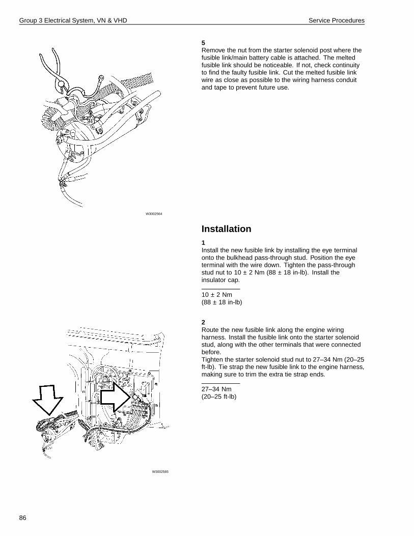
Group 3 Electrical System, VN & VHD Service Procedures
5
W3002564
Remove the nut from the starter solenoid post where thefusible link/main battery cable is attached. The meltedfusible link should be noticeable. If not, check continuityto find the faulty fusible link. Cut the melted fusible linkwire as close as possible to the wiring harness conduitand tape to prevent future use.
Installation1Install the new fusible link by installing the eye terminalonto the bulkhead pass-through stud. Position the eyeterminal with the wire down. Tighten the pass-throughstud nut to 10 ± 2 Nm (88 ± 18 in-lb). Install theinsulator cap.
10 ± 2 Nm(88 ± 18 in-lb)
2
W3002565
Route the new fusible link along the engine wiringharness. Install the fusible link onto the starter solenoidstud, along with the other terminals that were connectedbefore.Tighten the starter solenoid stud nut to 27–34 Nm (20–25ft-lb). Tie strap the new fusible link to the engine harness,making sure to trim the extra tie strap ends.
27–34 Nm(20–25 ft-lb)
86
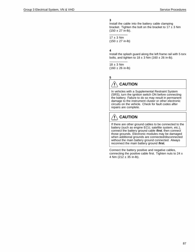
Group 3 Electrical System, VN & VHD Service Procedures
3Install the cable into the battery cable clampingbracket. Tighten the bolt on the bracket to 17 ± 3 Nm(150 ± 27 in-lb).
17 ± 3 Nm(150 ± 27 in-lb)
4Install the splash guard along the left frame rail with 5 torxbolts, and tighten to 18 ± 3 Nm (160 ± 26 in-lb).
18 ± 3 Nm(160 ± 26 in-lb)
5
CAUTION
In vehicles with a Supplemental Restraint System(SRS), turn the ignition switch ON before connectingthe battery. Failure to do so may result in permanentdamage to the instrument cluster or other electroniccircuits on the vehicle. Check for fault codes afterrepairs are complete.
CAUTION
If there are other ground cables to be connected to thebattery (such as engine ECU, satellite system, etc.),connect the battery ground cable first , then connectthose grounds. Electronic modules may be damagedwhen additional grounds are connected/disconnectedwithout the main battery ground connected. Alwaysreconnect the main battery ground first.
Connect the battery positive and negative cables,connecting the positive cable first. Tighten nuts to 24 ±4 Nm (212 ± 35 in-lb).
87
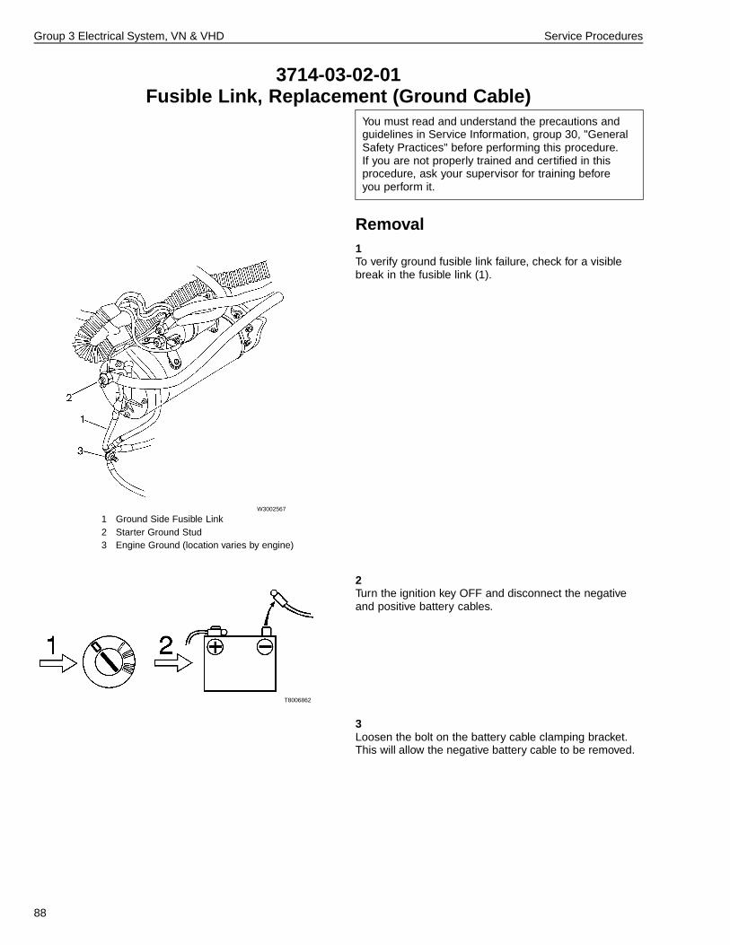
Group 3 Electrical System, VN & VHD Service Procedures
3714-03-02-01Fusible Link, Replacement (Ground Cable)
You must read and understand the precautions andguidelines in Service Information, group 30, "GeneralSafety Practices" before performing this procedure.If you are not properly trained and certified in thisprocedure, ask your supervisor for training beforeyou perform it.
Removal1
W3002567
1 Ground Side Fusible Link2 Starter Ground Stud3 Engine Ground (location varies by engine)
To verify ground fusible link failure, check for a visiblebreak in the fusible link (1).
2
T8006862
Turn the ignition key OFF and disconnect the negativeand positive battery cables.
3Loosen the bolt on the battery cable clamping bracket.This will allow the negative battery cable to be removed.
88
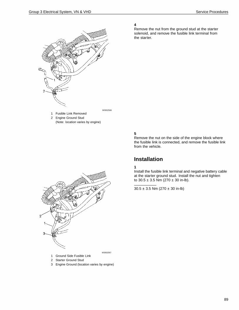
Group 3 Electrical System, VN & VHD Service Procedures
4
W3002566
1 Fusible Link Removed2 Engine Ground Stud
(Note: location varies by engine)
Remove the nut from the ground stud at the startersolenoid, and remove the fusible link terminal fromthe starter.
5Remove the nut on the side of the engine block wherethe fusible link is connected, and remove the fusible linkfrom the vehicle.
Installation1
W3002567
1 Ground Side Fusible Link2 Starter Ground Stud3 Engine Ground (location varies by engine)
Install the fusible link terminal and negative battery cableat the starter ground stud. Install the nut and tightento 30.5 ± 3.5 Nm (270 ± 30 in-lb).
30.5 ± 3.5 Nm (270 ± 30 in-lb)
89
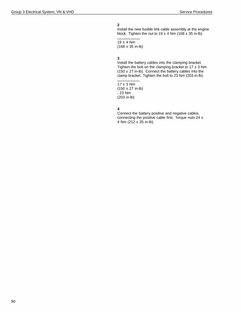
Group 3 Electrical System, VN & VHD Service Procedures
2Install the new fusible link cable assembly at the engineblock. Tighten the nut to 19 ± 4 Nm (168 ± 35 in-lb).
19 ± 4 Nm(168 ± 35 in-lb)
3Install the battery cables into the clamping bracket.Tighten the bolt on the clamping bracket to 17 ± 3 Nm(150 ± 27 in-lb). Connect the battery cables into theclamp bracket. Tighten the bolt to 23 Nm (203 in-lb).
17 ± 3 Nm(150 ± 27 in-lb), 23 Nm(203 in-lb)
4Connect the battery positive and negative cables,connecting the positive cable first. Torque nuts 24 ±4 Nm (212 ± 35 in-lb).
90
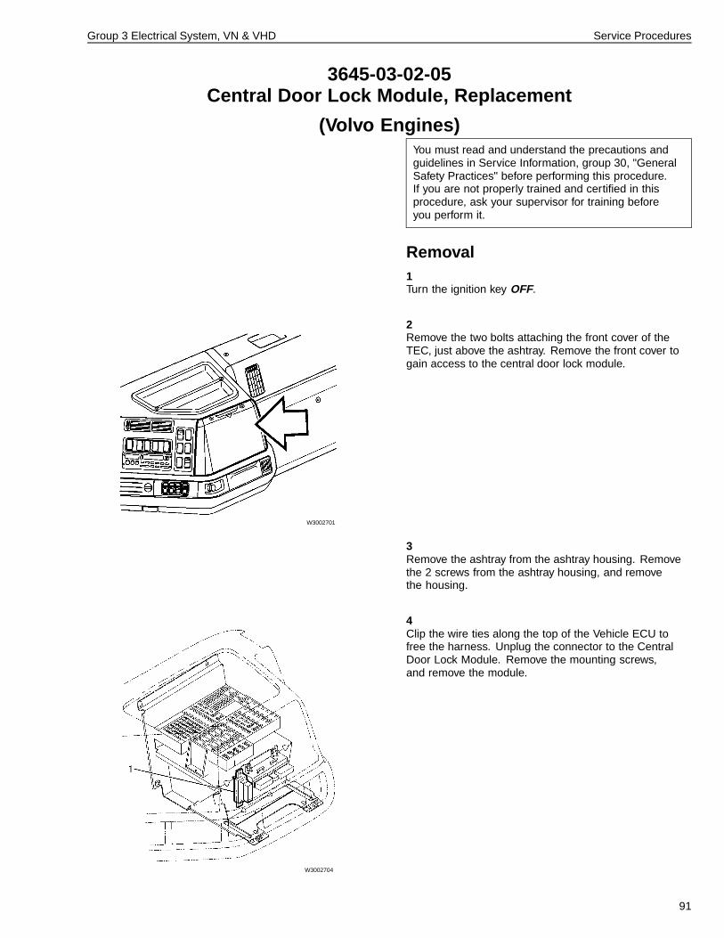
Group 3 Electrical System, VN & VHD Service Procedures
3645-03-02-05Central Door Lock Module, Replacement
(Volvo Engines)You must read and understand the precautions andguidelines in Service Information, group 30, "GeneralSafety Practices" before performing this procedure.If you are not properly trained and certified in thisprocedure, ask your supervisor for training beforeyou perform it.
Removal1Turn the ignition key OFF.
2
W3002701
Remove the two bolts attaching the front cover of theTEC, just above the ashtray. Remove the front cover togain access to the central door lock module.
3Remove the ashtray from the ashtray housing. Removethe 2 screws from the ashtray housing, and removethe housing.
4
W3002704
Clip the wire ties along the top of the Vehicle ECU tofree the harness. Unplug the connector to the CentralDoor Lock Module. Remove the mounting screws,and remove the module.
91
Group 3 Electrical System, VN & VHD Service Procedures
Installation1Install the new module in the same location where the oldmodule was installed. Bolt the module in place with 2 torxbolts. Tighten to 4.0 ± 0.5 Nm (35 ± 4 in-lb).
4.0 ± 0.5 Nm(35 ± 4 in-lb)
2Reconnect the module electrical connector. Install wireties to the VECU harness. Remove any excess wire tie.
3Install the ashtray housing, using the two mountingscrews. Tighten the screws to 1.5 ± 0.25 Nm(13.3 ± 2.2 in-lb). Install the ashtray.
1.5 ± 0.25 Nm(13.3 ± 2.2 in-lb)
4Install the front TEC cover. Tighten the bolts to 2.5 ± 0.5Nm (22.1 ± 4.4 in-lb).
2.5 ± 0.5 Nm(22.1 ± 4.4 in-lb)
92
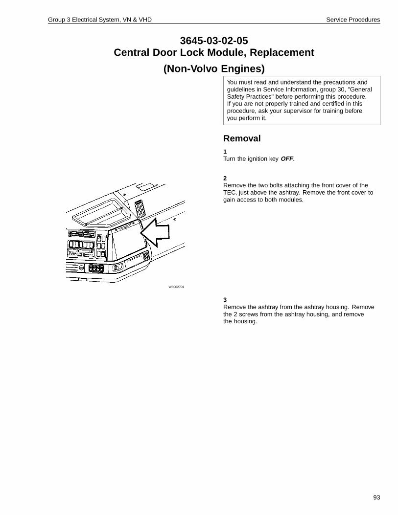
Group 3 Electrical System, VN & VHD Service Procedures
3645-03-02-05Central Door Lock Module, Replacement
(Non-Volvo Engines)You must read and understand the precautions andguidelines in Service Information, group 30, "GeneralSafety Practices" before performing this procedure.If you are not properly trained and certified in thisprocedure, ask your supervisor for training beforeyou perform it.
Removal1Turn the ignition key OFF.
2
W3002701
Remove the two bolts attaching the front cover of theTEC, just above the ashtray. Remove the front cover togain access to both modules.
3Remove the ashtray from the ashtray housing. Removethe 2 screws from the ashtray housing, and removethe housing.
93
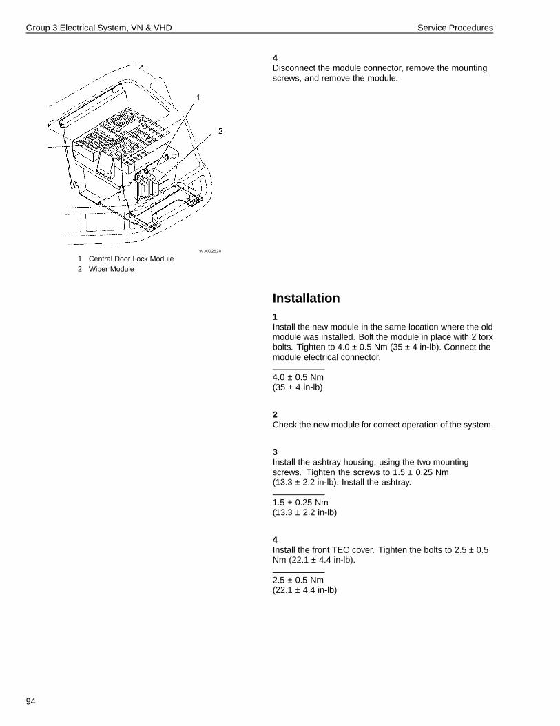
Group 3 Electrical System, VN & VHD Service Procedures
4
W3002524
1 Central Door Lock Module2 Wiper Module
Disconnect the module connector, remove the mountingscrews, and remove the module.
Installation1Install the new module in the same location where the oldmodule was installed. Bolt the module in place with 2 torxbolts. Tighten to 4.0 ± 0.5 Nm (35 ± 4 in-lb). Connect themodule electrical connector.
4.0 ± 0.5 Nm(35 ± 4 in-lb)
2Check the new module for correct operation of the system.
3Install the ashtray housing, using the two mountingscrews. Tighten the screws to 1.5 ± 0.25 Nm(13.3 ± 2.2 in-lb). Install the ashtray.
1.5 ± 0.25 Nm(13.3 ± 2.2 in-lb)
4Install the front TEC cover. Tighten the bolts to 2.5 ± 0.5Nm (22.1 ± 4.4 in-lb).
2.5 ± 0.5 Nm(22.1 ± 4.4 in-lb)
94
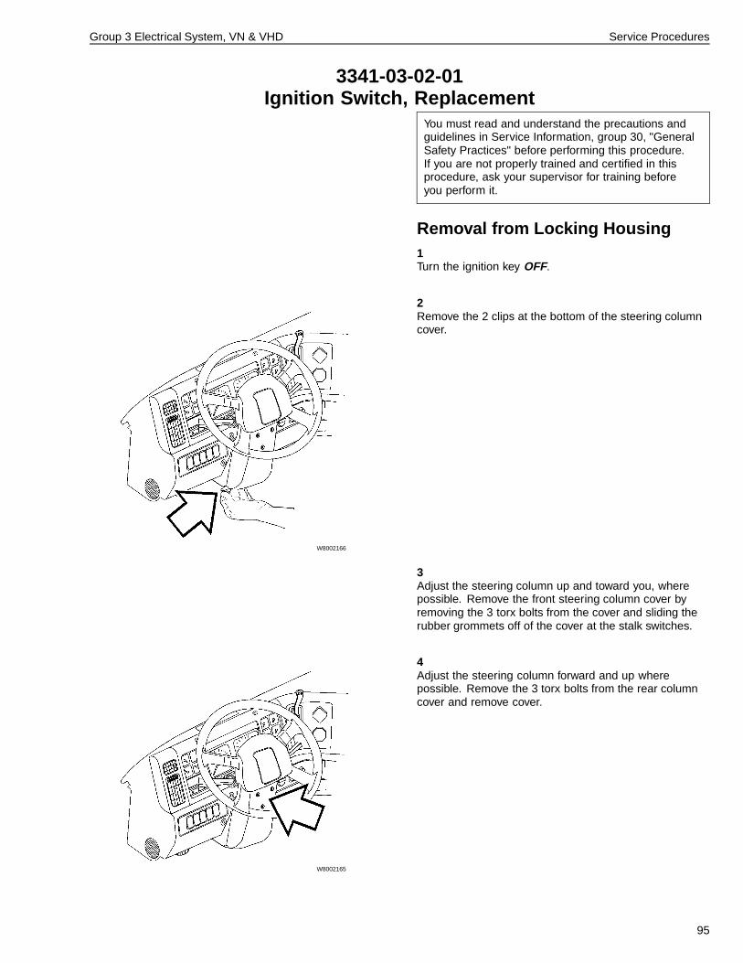
Group 3 Electrical System, VN & VHD Service Procedures
3341-03-02-01Ignition Switch, Replacement
You must read and understand the precautions andguidelines in Service Information, group 30, "GeneralSafety Practices" before performing this procedure.If you are not properly trained and certified in thisprocedure, ask your supervisor for training beforeyou perform it.
Removal from Locking Housing1Turn the ignition key OFF.
2
W8002166
Remove the 2 clips at the bottom of the steering columncover.
3Adjust the steering column up and toward you, wherepossible. Remove the front steering column cover byremoving the 3 torx bolts from the cover and sliding therubber grommets off of the cover at the stalk switches.
4
W8002165
Adjust the steering column forward and up wherepossible. Remove the 3 torx bolts from the rear columncover and remove cover.
95
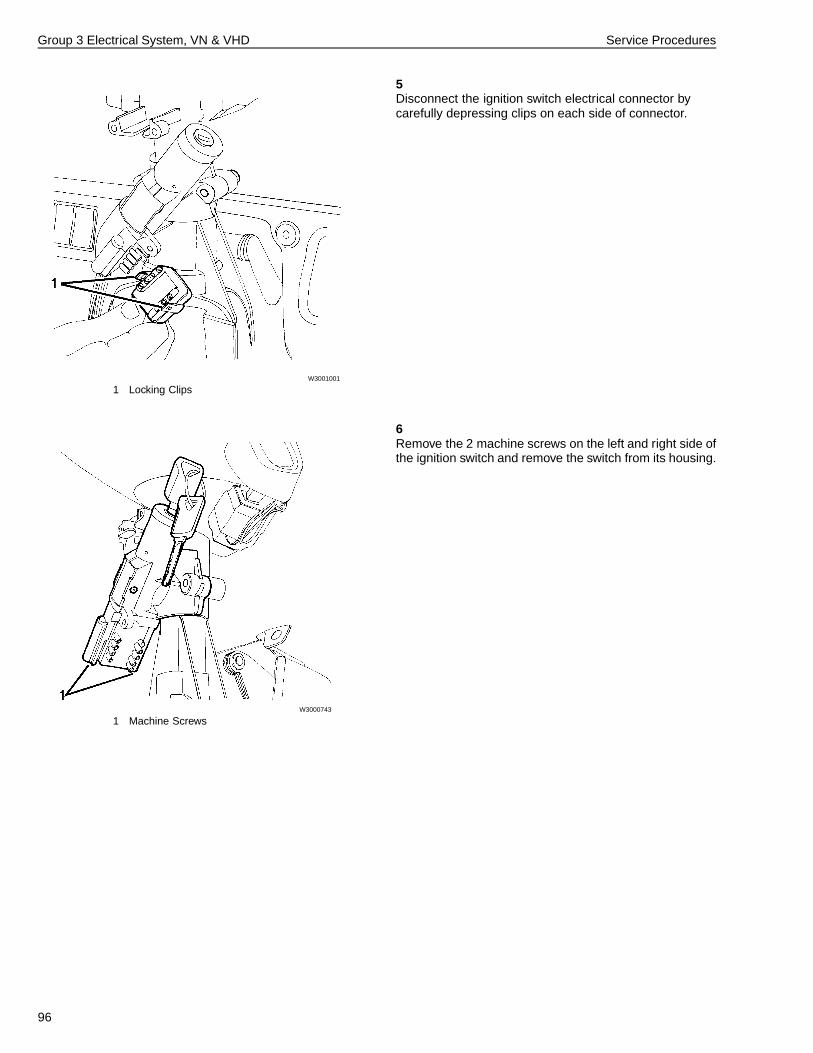
Group 3 Electrical System, VN & VHD Service Procedures
5
W3001001
1 Locking Clips
Disconnect the ignition switch electrical connector bycarefully depressing clips on each side of connector.
6
W3000743
1 Machine Screws
Remove the 2 machine screws on the left and right side ofthe ignition switch and remove the switch from its housing.
96
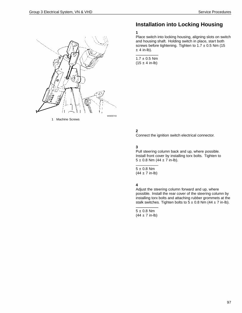
Group 3 Electrical System, VN & VHD Service Procedures
Installation into Locking Housing1
W3000743
1 Machine Screws
Place switch into locking housing, aligning slots on switchand housing shaft. Holding switch in place, start bothscrews before tightening. Tighten to 1.7 ± 0.5 Nm (15± 4 in-lb).
1.7 ± 0.5 Nm(15 ± 4 in-lb)
2Connect the ignition switch electrical connector.
3Pull steering column back and up, where possible.Install front cover by installing torx bolts. Tighten to5 ± 0.8 Nm (44 ± 7 in-lb).
5 ± 0.8 Nm(44 ± 7 in-lb)
4Adjust the steering column forward and up, wherepossible. Install the rear cover of the steering column byinstalling torx bolts and attaching rubber grommets at thestalk switches. Tighten bolts to 5 ± 0.8 Nm (44 ± 7 in-lb).
5 ± 0.8 Nm(44 ± 7 in-lb)
97
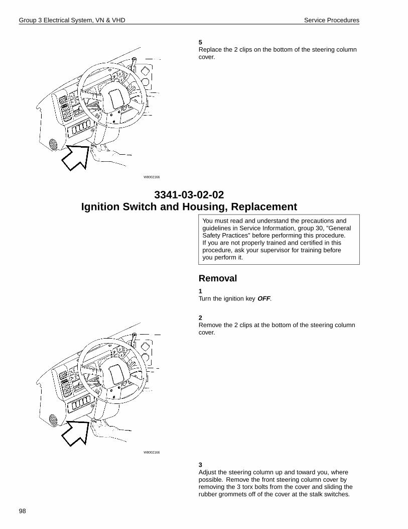
Group 3 Electrical System, VN & VHD Service Procedures
5
W8002166
Replace the 2 clips on the bottom of the steering columncover.
3341-03-02-02Ignition Switch and Housing, Replacement
You must read and understand the precautions andguidelines in Service Information, group 30, "GeneralSafety Practices" before performing this procedure.If you are not properly trained and certified in thisprocedure, ask your supervisor for training beforeyou perform it.
Removal1Turn the ignition key OFF.
2
W8002166
Remove the 2 clips at the bottom of the steering columncover.
3Adjust the steering column up and toward you, wherepossible. Remove the front steering column cover byremoving the 3 torx bolts from the cover and sliding therubber grommets off of the cover at the stalk switches.
98
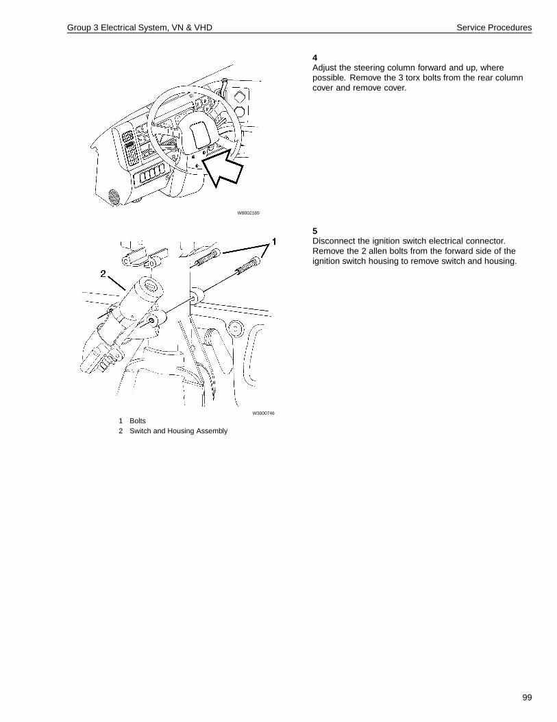
Group 3 Electrical System, VN & VHD Service Procedures
4
W8002165
Adjust the steering column forward and up, wherepossible. Remove the 3 torx bolts from the rear columncover and remove cover.
5
W3000746
1 Bolts2 Switch and Housing Assembly
Disconnect the ignition switch electrical connector.Remove the 2 allen bolts from the forward side of theignition switch housing to remove switch and housing.
99
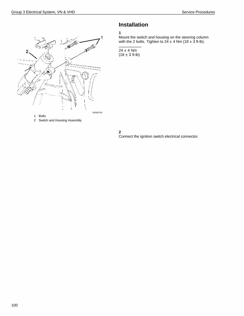
Group 3 Electrical System, VN & VHD Service Procedures
Installation1
W3000746
1 Bolts2 Switch and Housing Assembly
Mount the switch and housing on the steering columnwith the 2 bolts. Tighten to 24 ± 4 Nm (18 ± 3 ft-lb).
24 ± 4 Nm(18 ± 3 ft-lb)
2Connect the ignition switch electrical connector.
100
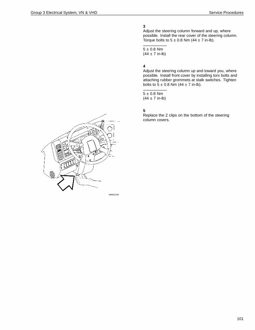
Group 3 Electrical System, VN & VHD Service Procedures
3Adjust the steering column forward and up, wherepossible. Install the rear cover of the steering column.Torque bolts to 5 ± 0.8 Nm (44 ± 7 in-lb).
5 ± 0.8 Nm(44 ± 7 in-lb)
4Adjust the steering column up and toward you, wherepossible. Install front cover by installing torx bolts andattaching rubber grommets at stalk switches. Tightenbolts to 5 ± 0.8 Nm (44 ± 7 in-lb).
5 ± 0.8 Nm(44 ± 7 in-lb)
5
W8002166
Replace the 2 clips on the bottom of the steeringcolumn covers.
101
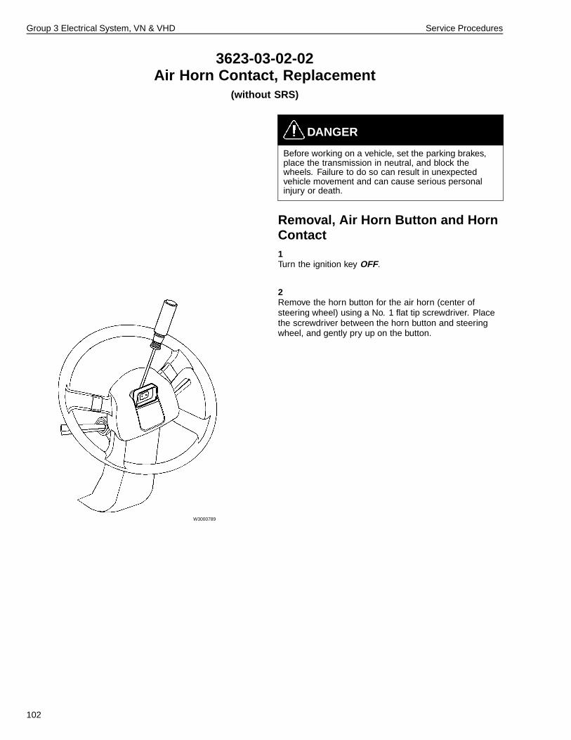
Group 3 Electrical System, VN & VHD Service Procedures
3623-03-02-02Air Horn Contact, Replacement
(without SRS)
DANGER
Before working on a vehicle, set the parking brakes,place the transmission in neutral, and block thewheels. Failure to do so can result in unexpectedvehicle movement and can cause serious personalinjury or death.
Removal, Air Horn Button and HornContact1Turn the ignition key OFF.
2
W3000789
Remove the horn button for the air horn (center ofsteering wheel) using a No. 1 flat tip screwdriver. Placethe screwdriver between the horn button and steeringwheel, and gently pry up on the button.
102
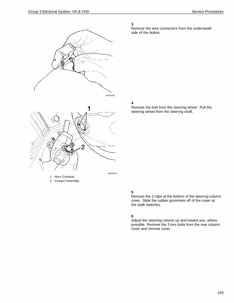
Group 3 Electrical System, VN & VHD Service Procedures
3
W3000790
Remove the wire connectors from the underneathside of the button.
4
W3000791
1 Horn Contacts2 Contact Assembly
Remove the bolt from the steering wheel. Pull thesteering wheel from the steering shaft.
5Remove the 2 clips at the bottom of the steering columncover. Slide the rubber grommets off of the cover atthe stalk switches.
6Adjust the steering column up and toward you, wherepossible. Remove the 3 torx bolts from the rear columncover and remove cover.
103
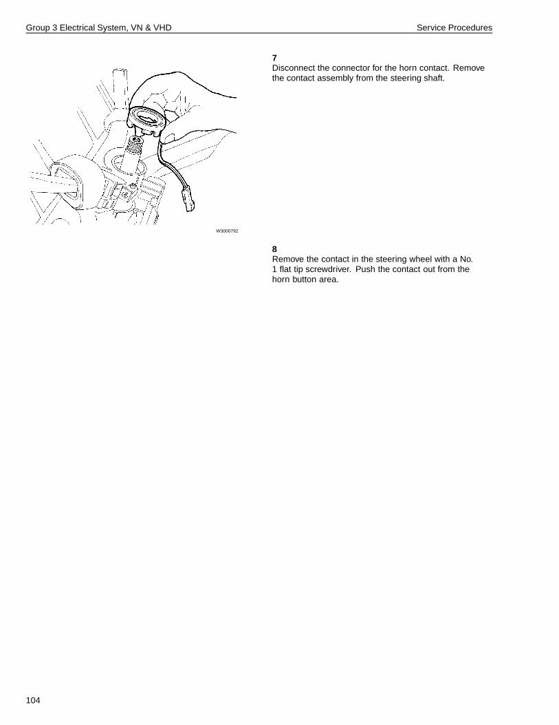
Group 3 Electrical System, VN & VHD Service Procedures
7
W3000792
Disconnect the connector for the horn contact. Removethe contact assembly from the steering shaft.
8Remove the contact in the steering wheel with a No.1 flat tip screwdriver. Push the contact out from thehorn button area.
104
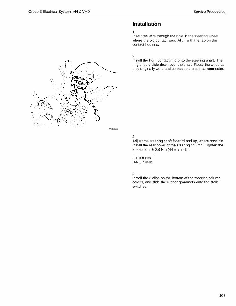
Group 3 Electrical System, VN & VHD Service Procedures
Installation1Insert the wire through the hole in the steering wheelwhere the old contact was. Align with the tab on thecontact housing.
2
W3000792
Install the horn contact ring onto the steering shaft. Thering should slide down over the shaft. Route the wires asthey originally were and connect the electrical connector.
3Adjust the steering shaft forward and up, where possible.Install the rear cover of the steering column. Tighten the3 bolts to 5 ± 0.8 Nm (44 ± 7 in-lb).
5 ± 0.8 Nm(44 ± 7 in-lb)
4Install the 2 clips on the bottom of the steering columncovers, and slide the rubber grommets onto the stalkswitches.
105
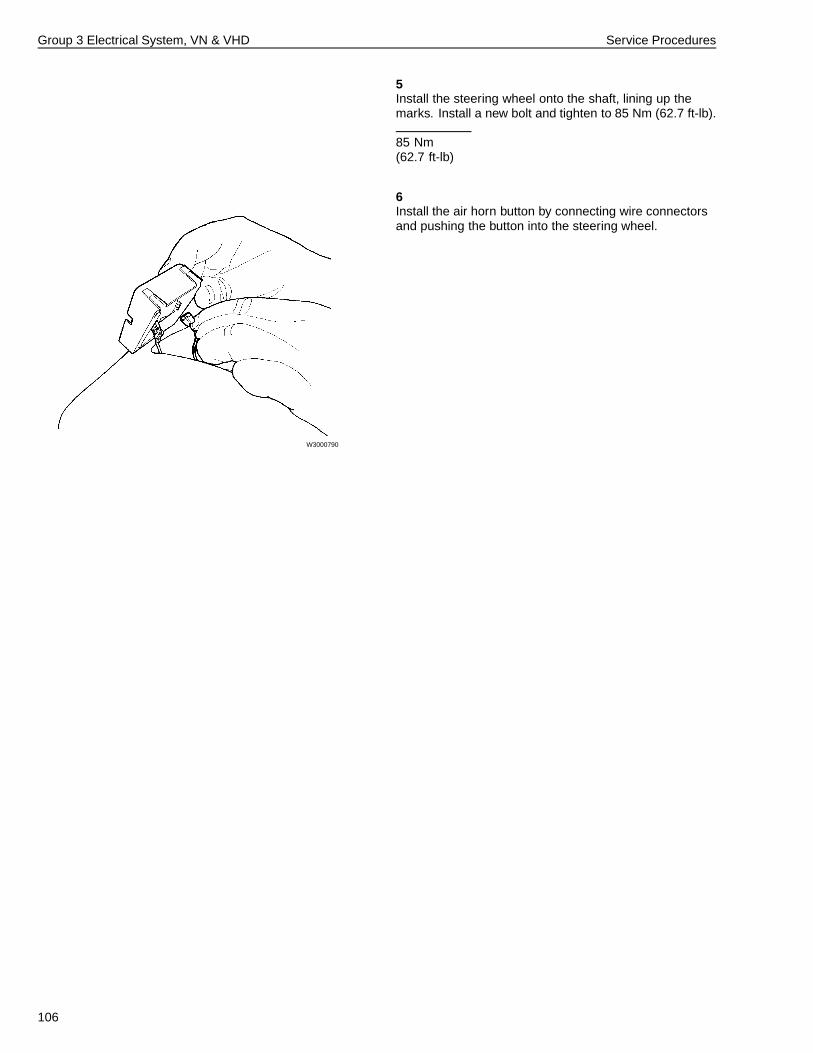
Group 3 Electrical System, VN & VHD Service Procedures
5Install the steering wheel onto the shaft, lining up themarks. Install a new bolt and tighten to 85 Nm (62.7 ft-lb).
85 Nm(62.7 ft-lb)
6
W3000790
Install the air horn button by connecting wire connectorsand pushing the button into the steering wheel.
106
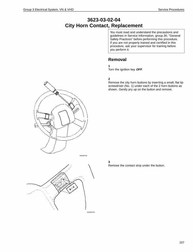
Group 3 Electrical System, VN & VHD Service Procedures
3623-03-02-04City Horn Contact, Replacement
You must read and understand the precautions andguidelines in Service Information, group 30, "GeneralSafety Practices" before performing this procedure.If you are not properly trained and certified in thisprocedure, ask your supervisor for training beforeyou perform it.
Removal1Turn the ignition key OFF.
2
W3000782
Remove the city horn buttons by inserting a small, flat tipscrewdriver (No. 1) under each of the 2 horn buttons asshown. Gently pry up on the button and remove.
3
W3000793
Remove the contact strip under the button.
107
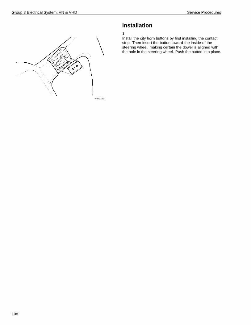
Group 3 Electrical System, VN & VHD Service Procedures
Installation1
W3000793
Install the city horn buttons by first installing the contactstrip. Then insert the button toward the inside of thesteering wheel, making certain the dowel is aligned withthe hole in the steering wheel. Push the button into place.
108
Group 3 Electrical System, VN & VHD Service Procedures
3621-03-02-03City Horn, Replacement
You must read and understand the precautions andguidelines in Service Information, group 30, "GeneralSafety Practices" before performing this procedure.If you are not properly trained and certified in thisprocedure, ask your supervisor for training beforeyou perform it.
Note: The city horn is generally located on the left sidein front of the radiator on the VHD, and inside the leftfront frame rail on the VN.
1Turn the ignition key OFF.
2Disconnect the electrical connector.
3Remove the mounting nut securing the horn to thebracket. Remove the horn from the vehicle.
4Position the replacement horn in the mounting bracket.Secure with the mounting nut.
5Connect the electrical connector and check hornoperation.
109
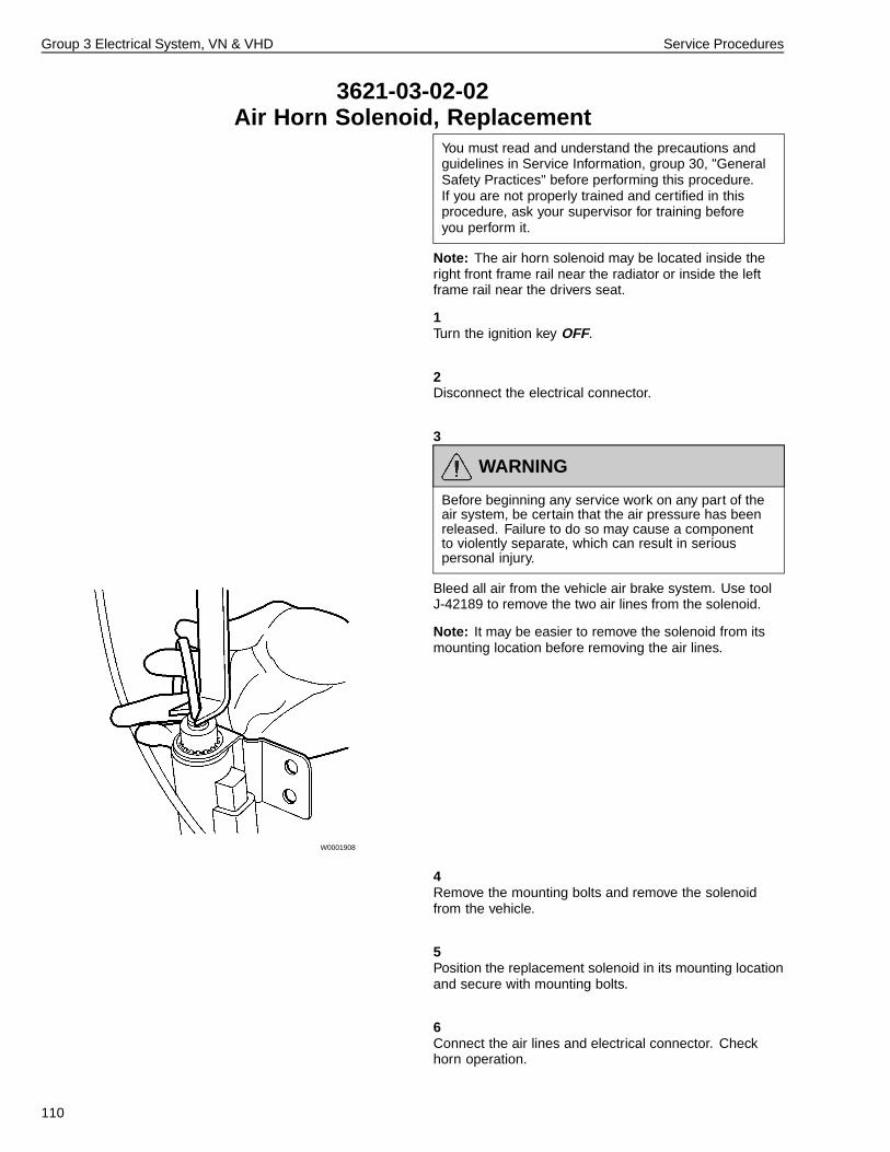
Group 3 Electrical System, VN & VHD Service Procedures
3621-03-02-02Air Horn Solenoid, Replacement
You must read and understand the precautions andguidelines in Service Information, group 30, "GeneralSafety Practices" before performing this procedure.If you are not properly trained and certified in thisprocedure, ask your supervisor for training beforeyou perform it.
Note: The air horn solenoid may be located inside theright front frame rail near the radiator or inside the leftframe rail near the drivers seat.
1Turn the ignition key OFF.
2Disconnect the electrical connector.
3
W0001908
WARNING
Before beginning any service work on any part of theair system, be certain that the air pressure has beenreleased. Failure to do so may cause a componentto violently separate, which can result in seriouspersonal injury.
Bleed all air from the vehicle air brake system. Use toolJ-42189 to remove the two air lines from the solenoid.
Note: It may be easier to remove the solenoid from itsmounting location before removing the air lines.
4Remove the mounting bolts and remove the solenoidfrom the vehicle.
5Position the replacement solenoid in its mounting locationand secure with mounting bolts.
6Connect the air lines and electrical connector. Checkhorn operation.
110
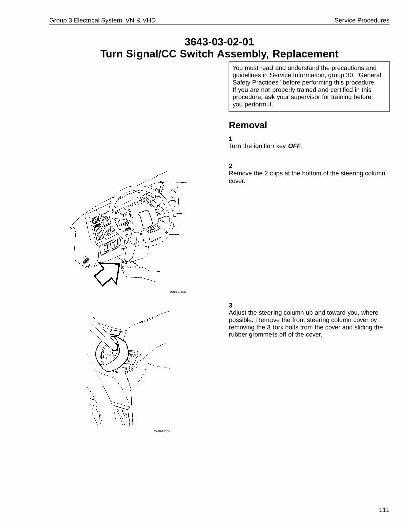
Group 3 Electrical System, VN & VHD Service Procedures
3643-03-02-01Turn Signal/CC Switch Assembly, Replacement
You must read and understand the precautions andguidelines in Service Information, group 30, "GeneralSafety Practices" before performing this procedure.If you are not properly trained and certified in thisprocedure, ask your supervisor for training beforeyou perform it.
Removal1Turn the ignition key OFF.
2
W8002166
Remove the 2 clips at the bottom of the steering columncover.
3
W3000653
Adjust the steering column up and toward you, wherepossible. Remove the front steering column cover byremoving the 3 torx bolts from the cover and sliding therubber grommets off of the cover.
111
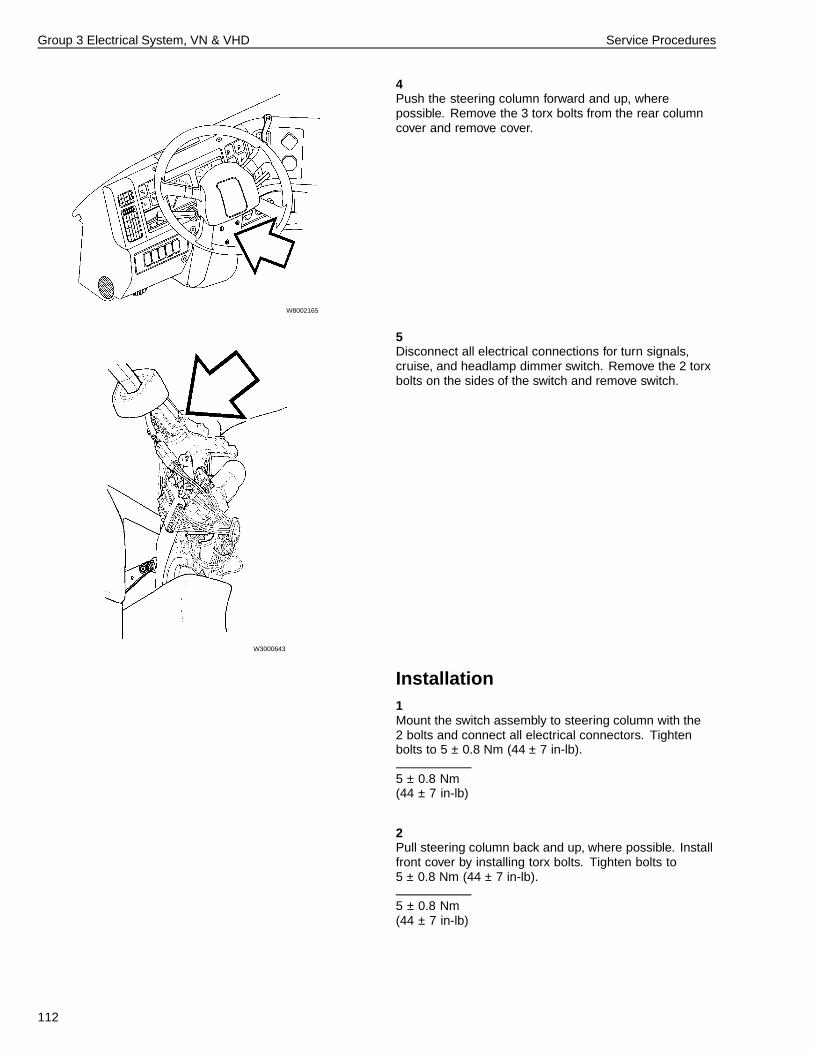
Group 3 Electrical System, VN & VHD Service Procedures
4
W8002165
Push the steering column forward and up, wherepossible. Remove the 3 torx bolts from the rear columncover and remove cover.
5
W3000643
Disconnect all electrical connections for turn signals,cruise, and headlamp dimmer switch. Remove the 2 torxbolts on the sides of the switch and remove switch.
Installation1Mount the switch assembly to steering column with the2 bolts and connect all electrical connectors. Tightenbolts to 5 ± 0.8 Nm (44 ± 7 in-lb).
5 ± 0.8 Nm(44 ± 7 in-lb)
2Pull steering column back and up, where possible. Installfront cover by installing torx bolts. Tighten bolts to5 ± 0.8 Nm (44 ± 7 in-lb).
5 ± 0.8 Nm(44 ± 7 in-lb)
112
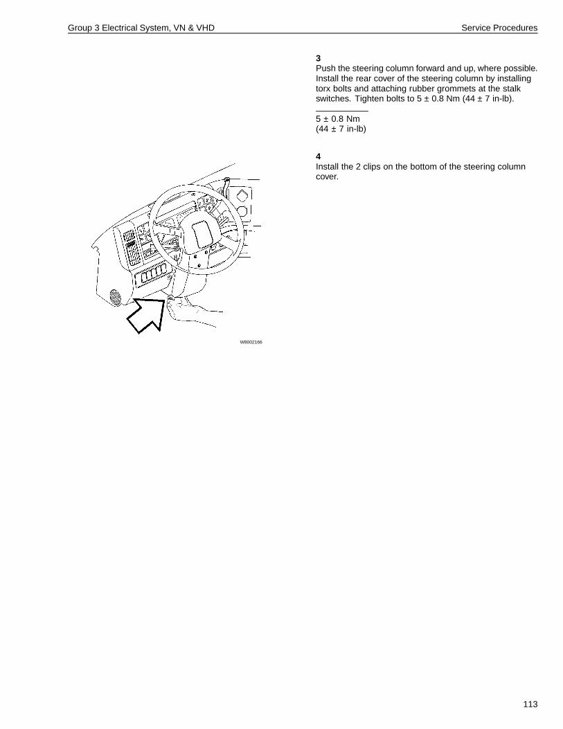
Group 3 Electrical System, VN & VHD Service Procedures
3Push the steering column forward and up, where possible.Install the rear cover of the steering column by installingtorx bolts and attaching rubber grommets at the stalkswitches. Tighten bolts to 5 ± 0.8 Nm (44 ± 7 in-lb).
5 ± 0.8 Nm(44 ± 7 in-lb)
4
W8002166
Install the 2 clips on the bottom of the steering columncover.
113
Group 3 Electrical System, VN & VHD Service Procedures
3646-03-02-11Hazard Warning Switch, Replacement
For a complete description of this procedure, see “Switch,Replacement (Left Dash Switches)” page 115.
3646-03-02-33Back of Cab Lamp Switch, Replacement
For a complete description of this procedure, see “Switch,Replacement (Left Dash Switches)” page 115.
3646-03-02-34Fan Switch, Replacement
For a complete description of this procedure, see “Switch,Replacement (Left Dash Switches)” page 115.
3646-03-02-35PTO Switch, Replacement
For a complete description of this procedure, see “Switch,Replacement (Left Dash Switches)” page 115.
3646-03-02-36Bunk Overhead Lamp Switch, Replacement
For a complete description of this procedure, see “Switch,Replacement (Left Dash Switches)” page 115.
3646-03-02-37Headlamp Interrupt Switch, Replacement
For a complete description of this procedure, see “Switch,Replacement (Left Dash Switches)” page 115.
3646-03-02-38Snowplow Lamp Switch, Replacement
For a complete description of this procedure, see “Switch,Replacement (Left Dash Switches)” page 115.
3646-03-02-39Smoke Detector Disable Switch, Replacement
For a complete description of this procedure, see “Switch,Replacement (Left Dash Switches)” page 115.
114
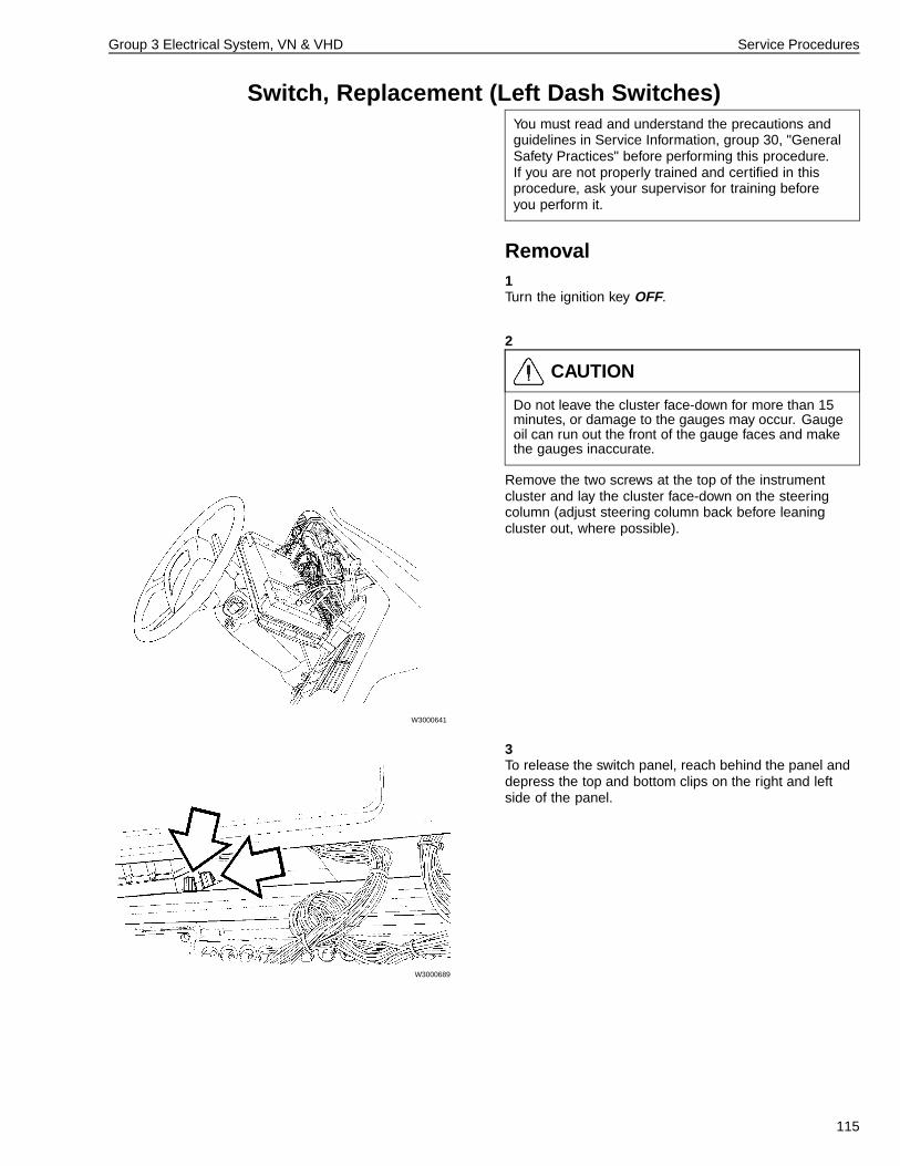
Group 3 Electrical System, VN & VHD Service Procedures
Switch, Replacement (Left Dash Switches)You must read and understand the precautions andguidelines in Service Information, group 30, "GeneralSafety Practices" before performing this procedure.If you are not properly trained and certified in thisprocedure, ask your supervisor for training beforeyou perform it.
Removal1Turn the ignition key OFF.
2
W3000641
CAUTION
Do not leave the cluster face-down for more than 15minutes, or damage to the gauges may occur. Gaugeoil can run out the front of the gauge faces and makethe gauges inaccurate.
Remove the two screws at the top of the instrumentcluster and lay the cluster face-down on the steeringcolumn (adjust steering column back before leaningcluster out, where possible).
3
W3000689
To release the switch panel, reach behind the panel anddepress the top and bottom clips on the right and leftside of the panel.
115
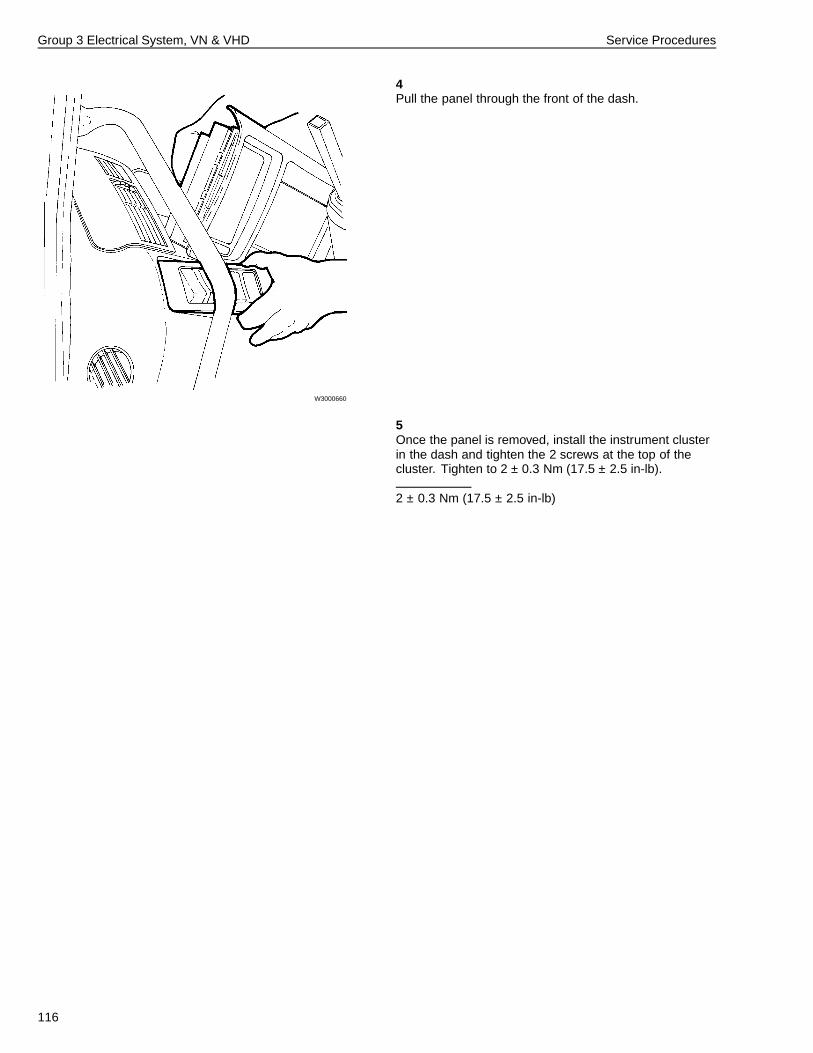
Group 3 Electrical System, VN & VHD Service Procedures
4
W3000660
Pull the panel through the front of the dash.
5Once the panel is removed, install the instrument clusterin the dash and tighten the 2 screws at the top of thecluster. Tighten to 2 ± 0.3 Nm (17.5 ± 2.5 in-lb).
2 ± 0.3 Nm (17.5 ± 2.5 in-lb)
116
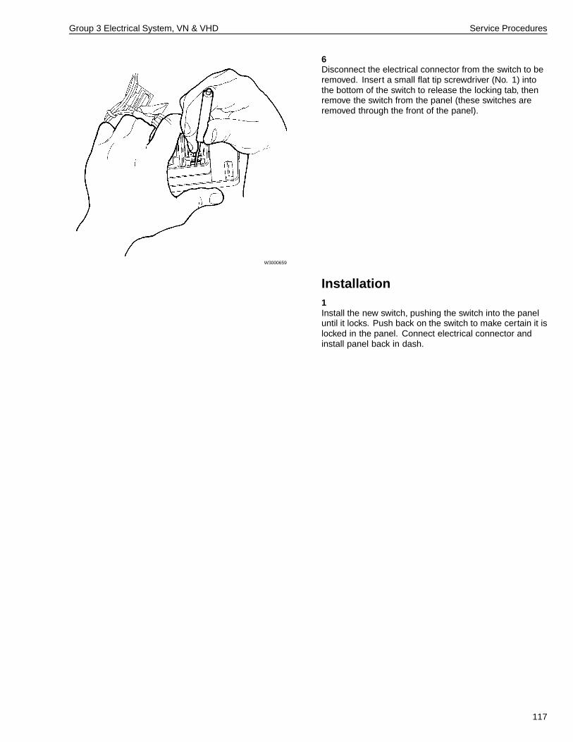
Group 3 Electrical System, VN & VHD Service Procedures
6
W3000659
Disconnect the electrical connector from the switch to beremoved. Insert a small flat tip screwdriver (No. 1) intothe bottom of the switch to release the locking tab, thenremove the switch from the panel (these switches areremoved through the front of the panel).
Installation1Install the new switch, pushing the switch into the paneluntil it locks. Push back on the switch to make certain it islocked in the panel. Connect electrical connector andinstall panel back in dash.
117
Group 3 Electrical System, VN & VHD Service Procedures
3646-03-02-29Sleeper Control Panel Switch, Replacement
For a complete description of this procedure, see“Right Dash/Auxiliary/Sleeper Control Panel Switch,Replacement” page 119.
3646-03-02-22Auxiliary Switch, Replacement
For a complete description of this procedure, see“Right Dash/Auxiliary/Sleeper Control Panel Switch,Replacement” page 119.
3646-03-02-24Marker Interrupt Switch, Replacement
For a complete description of this procedure, see“Right Dash/Auxiliary/Sleeper Control Panel Switch,Replacement” page 119.
3646-03-02-40Engine/Exhaust Brake Switch, Replacement
For a complete description of this procedure, see“Right Dash/Auxiliary/Sleeper Control Panel Switch,Replacement” page 119.
3646-03-02-41Traction Control Switch, Replacement
For a complete description of this procedure, see“Right Dash/Auxiliary/Sleeper Control Panel Switch,Replacement” page 119.
3646-03-02-26Heated Mirror Switch, Replacement
For a complete description of this procedure, see“Right Dash/Auxiliary/Sleeper Control Panel Switch,Replacement” page 119.
3646-03-02-42Lift Axle Switch, Replacement
For a complete description of this procedure, see“Right Dash/Auxiliary/Sleeper Control Panel Switch,Replacement” page 119.
3646-03-02-43Beacon Lamp Switch, Replacement
For a complete description of this procedure, see“Right Dash/Auxiliary/Sleeper Control Panel Switch,Replacement” page 119.
118
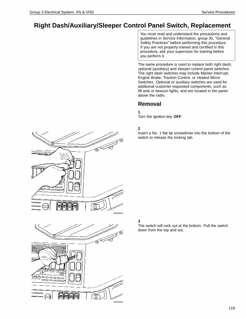
Group 3 Electrical System, VN & VHD Service Procedures
Right Dash/Auxiliary/Sleeper Control Panel Switch, ReplacementYou must read and understand the precautions andguidelines in Service Information, group 30, "GeneralSafety Practices" before performing this procedure.If you are not properly trained and certified in thisprocedure, ask your supervisor for training beforeyou perform it.
The same procedure is used to replace both right dash,optional (auxiliary) and sleeper control panel switches.The right dash switches may include Marker Interrupt,Engine Brake, Traction Control, or Heated MirrorSwitches. Optional or auxiliary switches are used foradditional customer requested components, such aslift axle or beacon lights, and are located in the panelabove the radio.
Removal1Turn the ignition key OFF.
2
W3000644
Insert a No. 1 flat tip screwdriver into the bottom of theswitch to release the locking tab.
3
W3000645
The switch will rock out at the bottom. Pull the switchdown from the top and out.
119
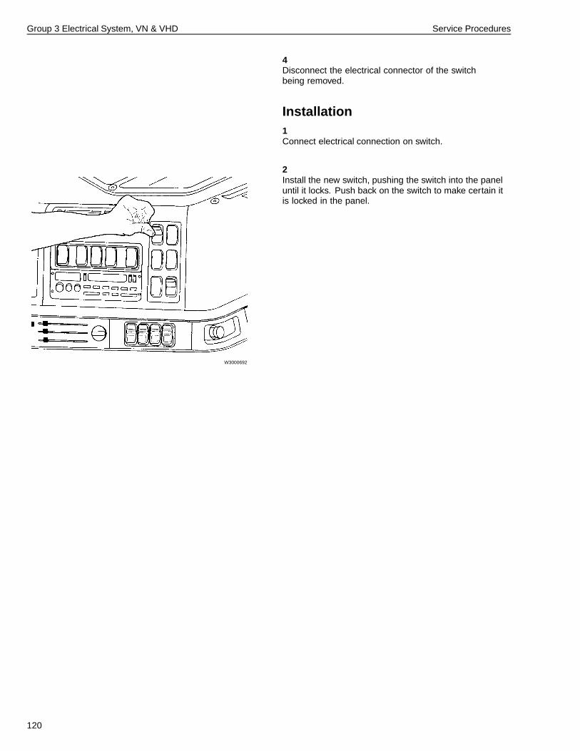
Group 3 Electrical System, VN & VHD Service Procedures
4Disconnect the electrical connector of the switchbeing removed.
Installation1Connect electrical connection on switch.
2
W3000692
Install the new switch, pushing the switch into the paneluntil it locks. Push back on the switch to make certain itis locked in the panel.
120
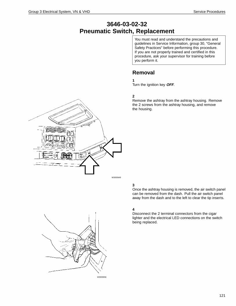
Group 3 Electrical System, VN & VHD Service Procedures
3646-03-02-32Pneumatic Switch, Replacement
You must read and understand the precautions andguidelines in Service Information, group 30, "GeneralSafety Practices" before performing this procedure.If you are not properly trained and certified in thisprocedure, ask your supervisor for training beforeyou perform it.
Removal1Turn the ignition key OFF.
2
W3000649
Remove the ashtray from the ashtray housing. Removethe 2 screws from the ashtray housing, and removethe housing.
3Once the ashtray housing is removed, the air switch panelcan be removed from the dash. Pull the air switch panelaway from the dash and to the left to clear the tip inserts.
4
W3000656
Disconnect the 2 terminal connectors from the cigarlighter and the electrical LED connections on the switchbeing replaced.
121
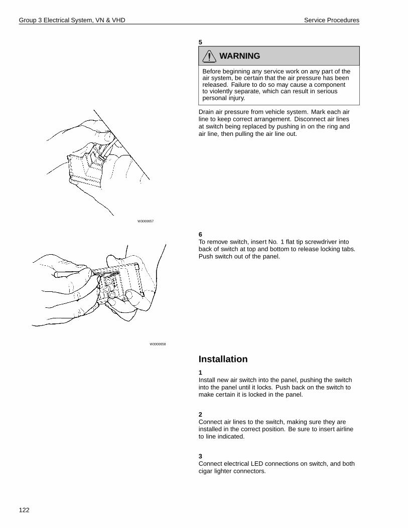
Group 3 Electrical System, VN & VHD Service Procedures
5
W3000657
WARNING
Before beginning any service work on any part of theair system, be certain that the air pressure has beenreleased. Failure to do so may cause a componentto violently separate, which can result in seriouspersonal injury.
Drain air pressure from vehicle system. Mark each airline to keep correct arrangement. Disconnect air linesat switch being replaced by pushing in on the ring andair line, then pulling the air line out.
6
W3000658
To remove switch, insert No. 1 flat tip screwdriver intoback of switch at top and bottom to release locking tabs.Push switch out of the panel.
Installation1Install new air switch into the panel, pushing the switchinto the panel until it locks. Push back on the switch tomake certain it is locked in the panel.
2Connect air lines to the switch, making sure they areinstalled in the correct position. Be sure to insert airlineto line indicated.
3Connect electrical LED connections on switch, and bothcigar lighter connectors.
122
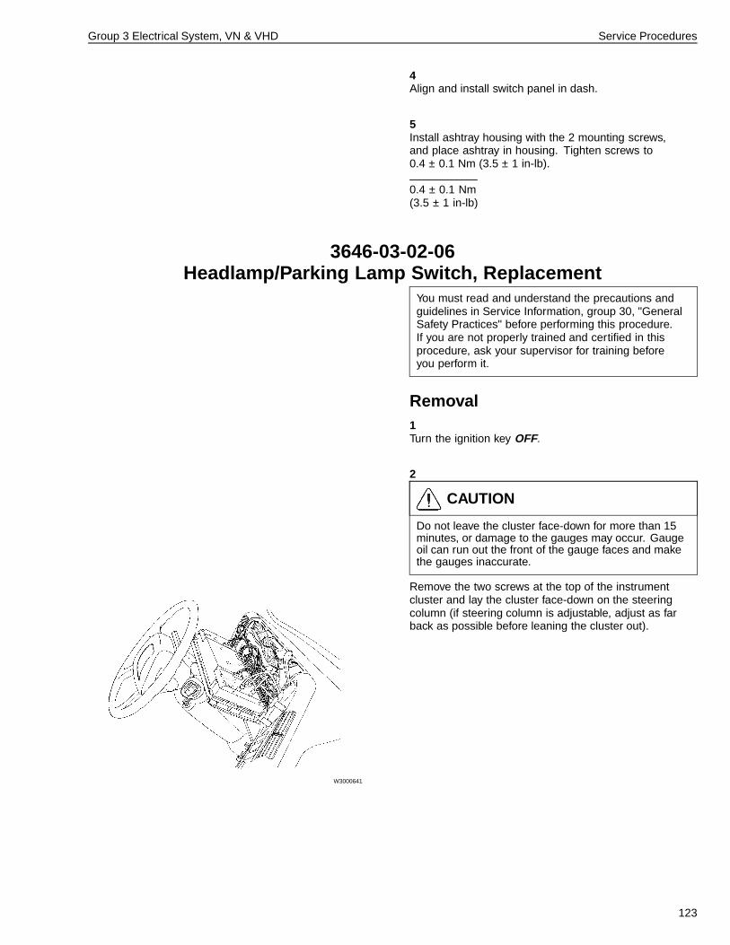
Group 3 Electrical System, VN & VHD Service Procedures
4Align and install switch panel in dash.
5Install ashtray housing with the 2 mounting screws,and place ashtray in housing. Tighten screws to0.4 ± 0.1 Nm (3.5 ± 1 in-lb).
0.4 ± 0.1 Nm(3.5 ± 1 in-lb)
3646-03-02-06Headlamp/Parking Lamp Switch, Replacement
You must read and understand the precautions andguidelines in Service Information, group 30, "GeneralSafety Practices" before performing this procedure.If you are not properly trained and certified in thisprocedure, ask your supervisor for training beforeyou perform it.
Removal1Turn the ignition key OFF.
2
W3000641
CAUTION
Do not leave the cluster face-down for more than 15minutes, or damage to the gauges may occur. Gaugeoil can run out the front of the gauge faces and makethe gauges inaccurate.
Remove the two screws at the top of the instrumentcluster and lay the cluster face-down on the steeringcolumn (if steering column is adjustable, adjust as farback as possible before leaning the cluster out).
123
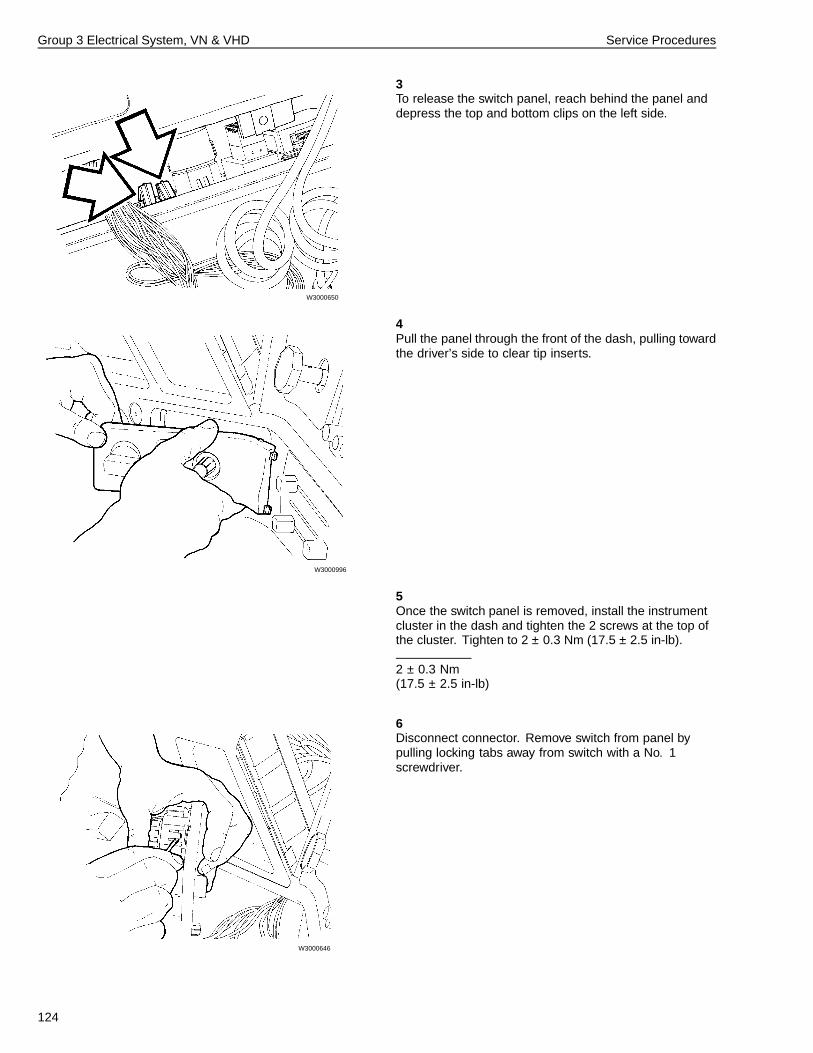
Group 3 Electrical System, VN & VHD Service Procedures
3
W3000650
To release the switch panel, reach behind the panel anddepress the top and bottom clips on the left side.
4
W3000996
Pull the panel through the front of the dash, pulling towardthe driver’s side to clear tip inserts.
5Once the switch panel is removed, install the instrumentcluster in the dash and tighten the 2 screws at the top ofthe cluster. Tighten to 2 ± 0.3 Nm (17.5 ± 2.5 in-lb).
2 ± 0.3 Nm(17.5 ± 2.5 in-lb)
6
W3000646
Disconnect connector. Remove switch from panel bypulling locking tabs away from switch with a No. 1screwdriver.
124
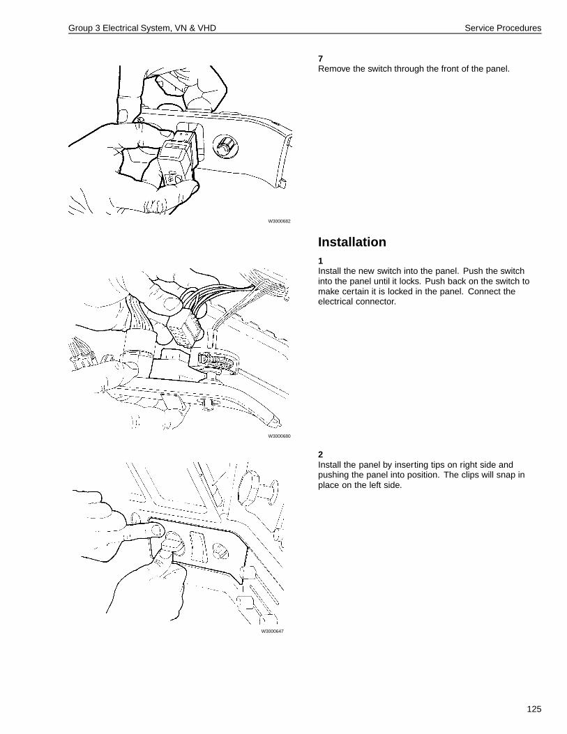
Group 3 Electrical System, VN & VHD Service Procedures
7
W3000682
Remove the switch through the front of the panel.
Installation1
W3000680
Install the new switch into the panel. Push the switchinto the panel until it locks. Push back on the switch tomake certain it is locked in the panel. Connect theelectrical connector.
2
W3000647
Install the panel by inserting tips on right side andpushing the panel into position. The clips will snap inplace on the left side.
125
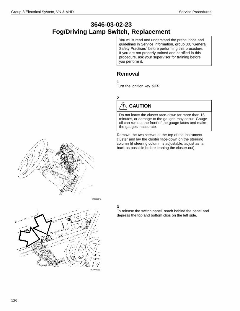
Group 3 Electrical System, VN & VHD Service Procedures
3646-03-02-23Fog/Driving Lamp Switch, Replacement
You must read and understand the precautions andguidelines in Service Information, group 30, "GeneralSafety Practices" before performing this procedure.If you are not properly trained and certified in thisprocedure, ask your supervisor for training beforeyou perform it.
Removal1Turn the ignition key OFF.
2
W3000641
CAUTION
Do not leave the cluster face-down for more than 15minutes, or damage to the gauges may occur. Gaugeoil can run out the front of the gauge faces and makethe gauges inaccurate.
Remove the two screws at the top of the instrumentcluster and lay the cluster face-down on the steeringcolumn (if steering column is adjustable, adjust as farback as possible before leaning the cluster out).
3
W3000650
To release the switch panel, reach behind the panel anddepress the top and bottom clips on the left side.
126
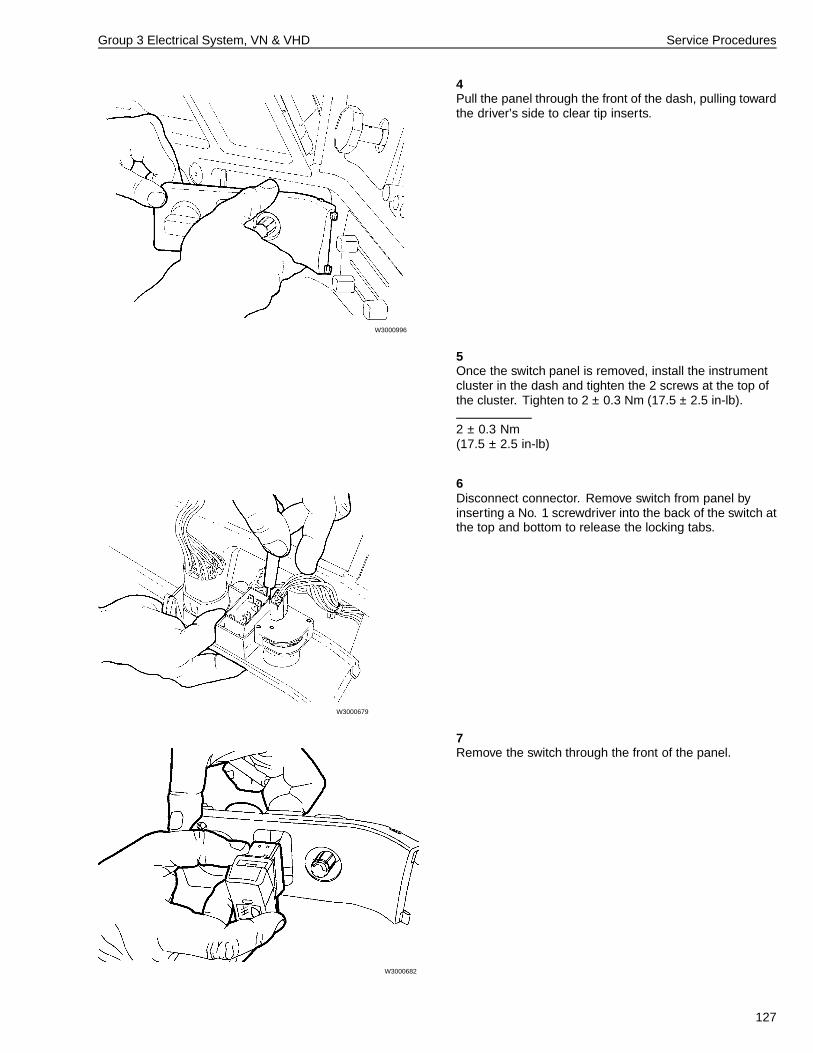
Group 3 Electrical System, VN & VHD Service Procedures
4
W3000996
Pull the panel through the front of the dash, pulling towardthe driver’s side to clear tip inserts.
5Once the switch panel is removed, install the instrumentcluster in the dash and tighten the 2 screws at the top ofthe cluster. Tighten to 2 ± 0.3 Nm (17.5 ± 2.5 in-lb).
2 ± 0.3 Nm(17.5 ± 2.5 in-lb)
6
W3000679
Disconnect connector. Remove switch from panel byinserting a No. 1 screwdriver into the back of the switch atthe top and bottom to release the locking tabs.
7
W3000682
Remove the switch through the front of the panel.
127
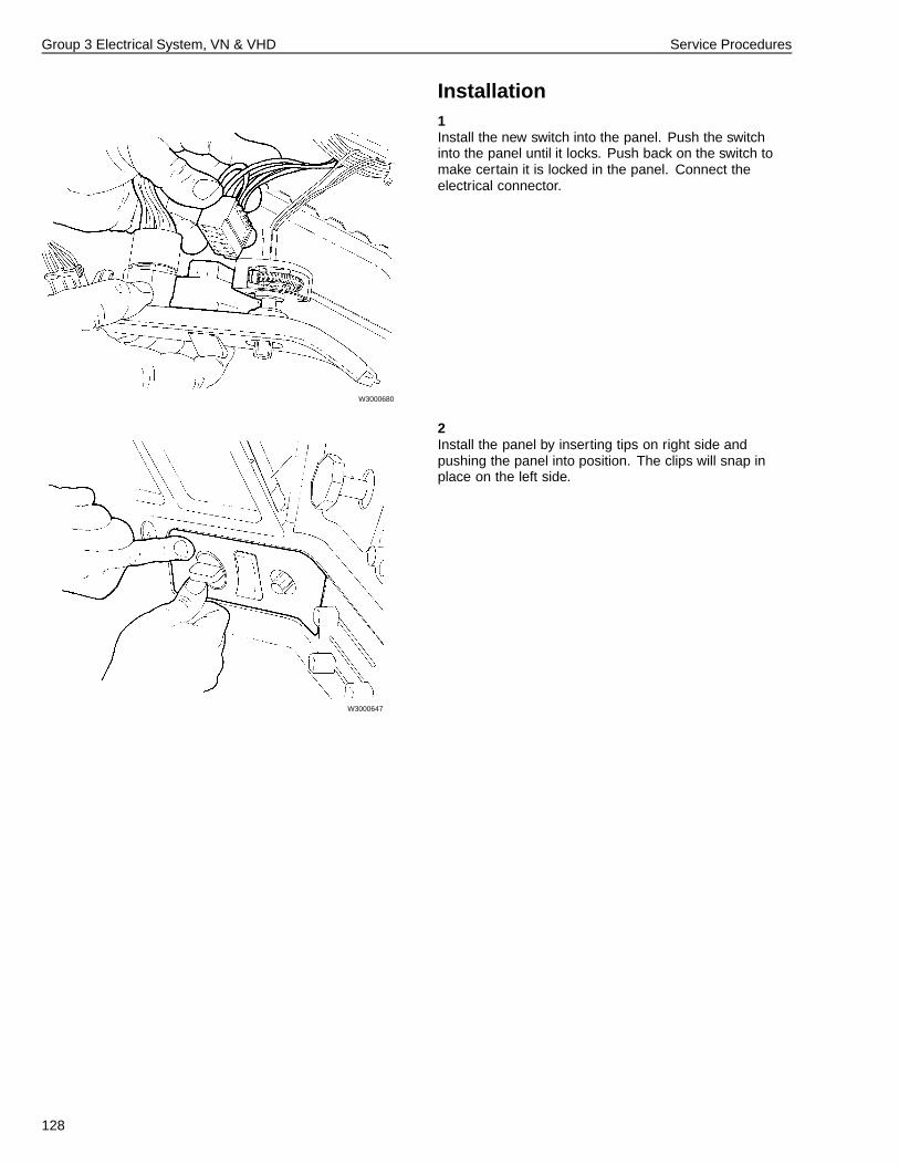
Group 3 Electrical System, VN & VHD Service Procedures
Installation1
W3000680
Install the new switch into the panel. Push the switchinto the panel until it locks. Push back on the switch tomake certain it is locked in the panel. Connect theelectrical connector.
2
W3000647
Install the panel by inserting tips on right side andpushing the panel into position. The clips will snap inplace on the left side.
128
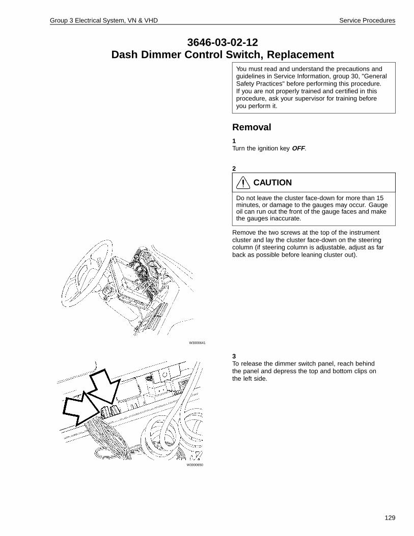
Group 3 Electrical System, VN & VHD Service Procedures
3646-03-02-12Dash Dimmer Control Switch, Replacement
You must read and understand the precautions andguidelines in Service Information, group 30, "GeneralSafety Practices" before performing this procedure.If you are not properly trained and certified in thisprocedure, ask your supervisor for training beforeyou perform it.
Removal1Turn the ignition key OFF.
2
W3000641
CAUTION
Do not leave the cluster face-down for more than 15minutes, or damage to the gauges may occur. Gaugeoil can run out the front of the gauge faces and makethe gauges inaccurate.
Remove the two screws at the top of the instrumentcluster and lay the cluster face-down on the steeringcolumn (if steering column is adjustable, adjust as farback as possible before leaning cluster out).
3
W3000650
To release the dimmer switch panel, reach behindthe panel and depress the top and bottom clips onthe left side.
129
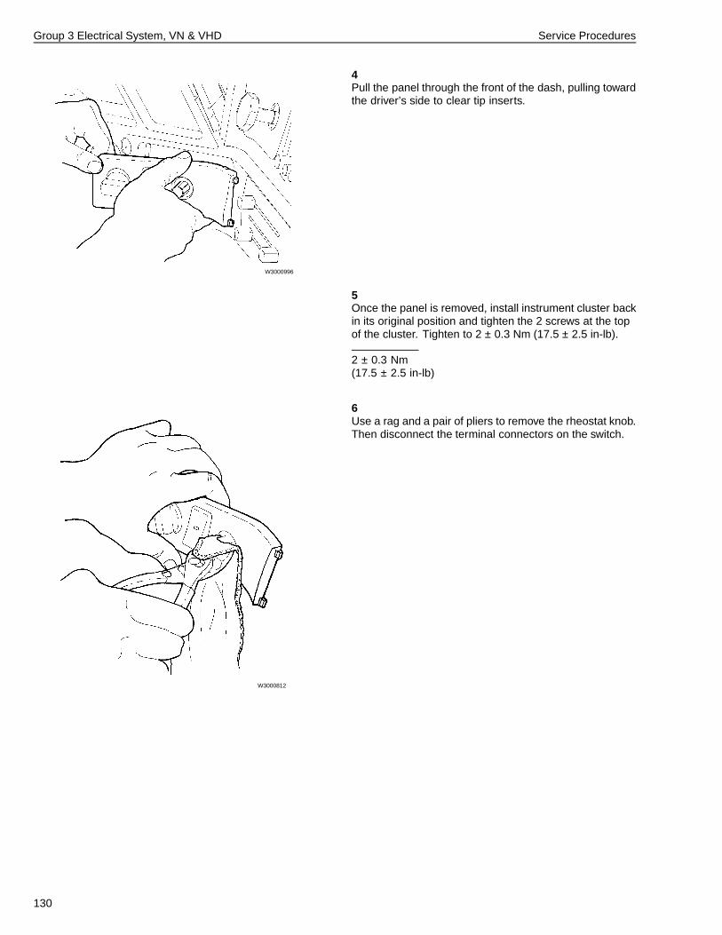
Group 3 Electrical System, VN & VHD Service Procedures
4
W3000996
Pull the panel through the front of the dash, pulling towardthe driver’s side to clear tip inserts.
5Once the panel is removed, install instrument cluster backin its original position and tighten the 2 screws at the topof the cluster. Tighten to 2 ± 0.3 Nm (17.5 ± 2.5 in-lb).
2 ± 0.3 Nm(17.5 ± 2.5 in-lb)
6
W3000812
Use a rag and a pair of pliers to remove the rheostat knob.Then disconnect the terminal connectors on the switch.
130
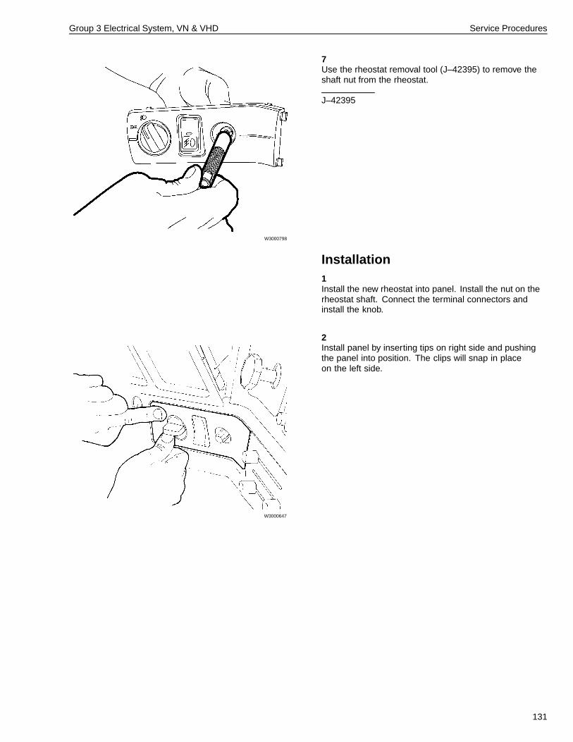
Group 3 Electrical System, VN & VHD Service Procedures
7
W3000798
Use the rheostat removal tool (J–42395) to remove theshaft nut from the rheostat.
J–42395
Installation1Install the new rheostat into panel. Install the nut on therheostat shaft. Connect the terminal connectors andinstall the knob.
2
W3000647
Install panel by inserting tips on right side and pushingthe panel into position. The clips will snap in placeon the left side.
131
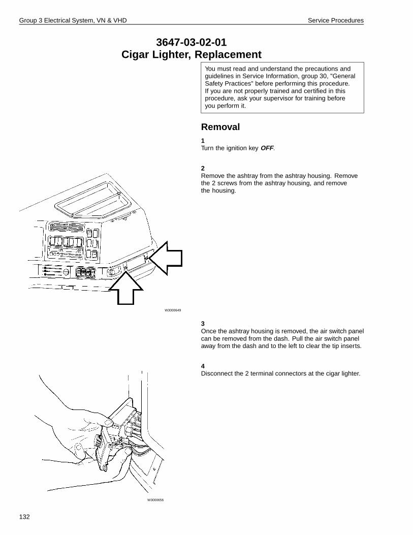
Group 3 Electrical System, VN & VHD Service Procedures
3647-03-02-01Cigar Lighter, Replacement
You must read and understand the precautions andguidelines in Service Information, group 30, "GeneralSafety Practices" before performing this procedure.If you are not properly trained and certified in thisprocedure, ask your supervisor for training beforeyou perform it.
Removal1Turn the ignition key OFF.
2
W3000649
Remove the ashtray from the ashtray housing. Removethe 2 screws from the ashtray housing, and removethe housing.
3Once the ashtray housing is removed, the air switch panelcan be removed from the dash. Pull the air switch panelaway from the dash and to the left to clear the tip inserts.
4
W3000656
Disconnect the 2 terminal connectors at the cigar lighter.
132
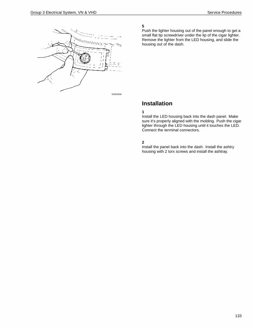
Group 3 Electrical System, VN & VHD Service Procedures
5
W3000696
Push the lighter housing out of the panel enough to get asmall flat tip screwdriver under the lip of the cigar lighter.Remove the lighter from the LED housing, and slide thehousing out of the dash.
Installation1Install the LED housing back into the dash panel. Makesure it’s properly aligned with the molding. Push the cigarlighter through the LED housing until it touches the LED.Connect the terminal connectors.
2Install the panel back into the dash. Install the ashtryhousing with 2 torx screws and install the ashtray.
133
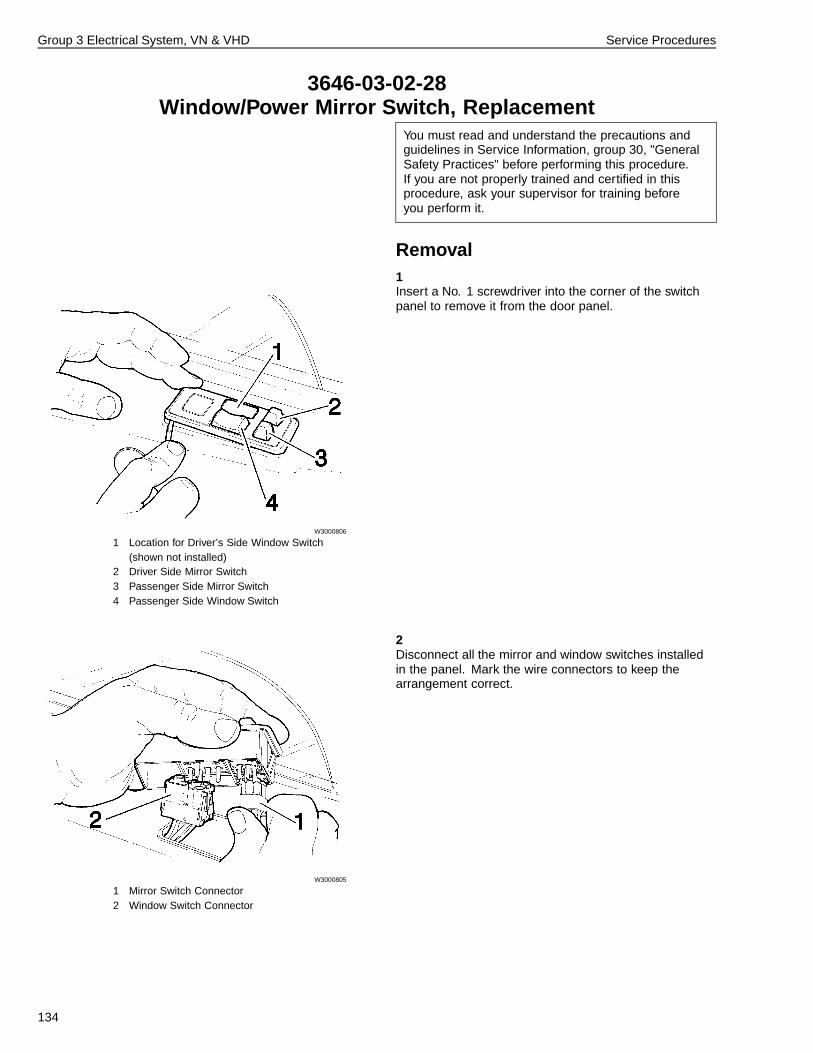
Group 3 Electrical System, VN & VHD Service Procedures
3646-03-02-28Window/Power Mirror Switch, Replacement
You must read and understand the precautions andguidelines in Service Information, group 30, "GeneralSafety Practices" before performing this procedure.If you are not properly trained and certified in thisprocedure, ask your supervisor for training beforeyou perform it.
Removal1
W3000806
1 Location for Driver’s Side Window Switch(shown not installed)
2 Driver Side Mirror Switch3 Passenger Side Mirror Switch4 Passenger Side Window Switch
Insert a No. 1 screwdriver into the corner of the switchpanel to remove it from the door panel.
2
W3000805
1 Mirror Switch Connector2 Window Switch Connector
Disconnect all the mirror and window switches installedin the panel. Mark the wire connectors to keep thearrangement correct.
134
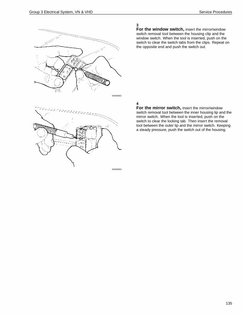
Group 3 Electrical System, VN & VHD Service Procedures
3
W3000802
For the window switch, insert the mirror/windowswitch removal tool between the housing clip and thewindow switch. When the tool is inserted, push on theswitch to clear the switch tabs from the clips. Repeat onthe opposite end and push the switch out.
4
W3000803
For the mirror switch, insert the mirror/windowswitch removal tool between the inner housing lip and themirror switch. When the tool is inserted, push on theswitch to clear the locking tab. Then insert the removaltool between the outer lip and the mirror switch. Keepinga steady pressure, push the switch out of the housing.
135
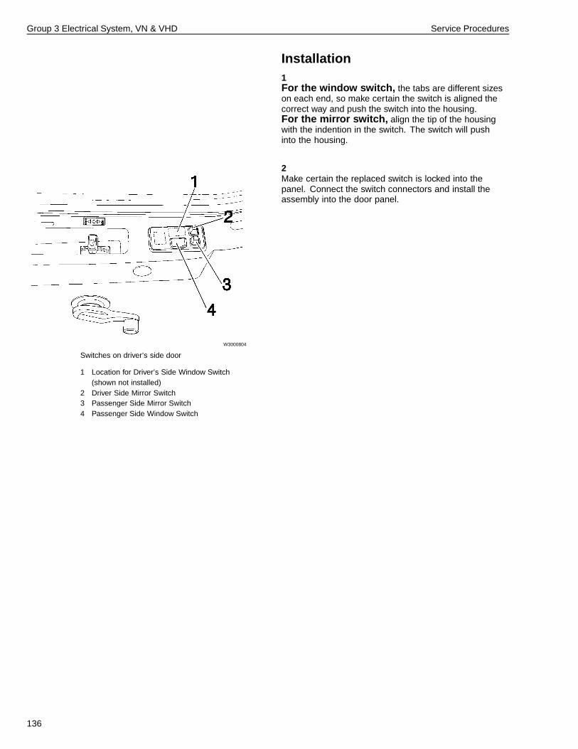
Group 3 Electrical System, VN & VHD Service Procedures
Installation1For the window switch, the tabs are different sizeson each end, so make certain the switch is aligned thecorrect way and push the switch into the housing.For the mirror switch, align the tip of the housingwith the indention in the switch. The switch will pushinto the housing.
2
W3000804
Switches on driver’s side door
1 Location for Driver’s Side Window Switch(shown not installed)
2 Driver Side Mirror Switch3 Passenger Side Mirror Switch4 Passenger Side Window Switch
Make certain the replaced switch is locked into thepanel. Connect the switch connectors and install theassembly into the door panel.
136
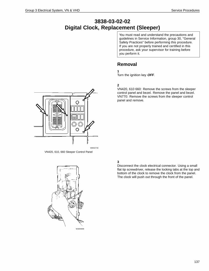
Group 3 Electrical System, VN & VHD Service Procedures
3838-03-02-02Digital Clock, Replacement (Sleeper)
You must read and understand the precautions andguidelines in Service Information, group 30, "GeneralSafety Practices" before performing this procedure.If you are not properly trained and certified in thisprocedure, ask your supervisor for training beforeyou perform it.
Removal1Turn the ignition key OFF.
2
W8002730
VN420, 610, 660 Sleeper Control Panel
VN420, 610 660: Remove the screws from the sleepercontrol panel and bezel. Remove the panel and bezel.VN770: Remove the screws from the sleeper controlpanel and remove.
3
W3000698
Disconnect the clock electrical connector. Using a smallflat tip screwdriver, release the locking tabs at the top andbottom of the clock to remove the clock from the panel.The clock will push out through the front of the panel.
137
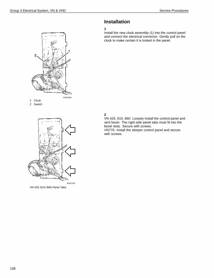
Group 3 Electrical System, VN & VHD Service Procedures
Installation1
W3000999
1 Clock2 Switch
Install the new clock assembly (1) into the control paneland connect the electrical connector. Gently pull on theclock to make certain it is locked in the panel.
2
W3001000
VN 420 /610 /660 Panel Tabs
VN 420, 610, 660: Loosely install the control panel andvent bezel. The right side panel tabs must fit into thebezel slots. Secure with screws.VN770: Install the sleeper control panel and securewith screws.
138
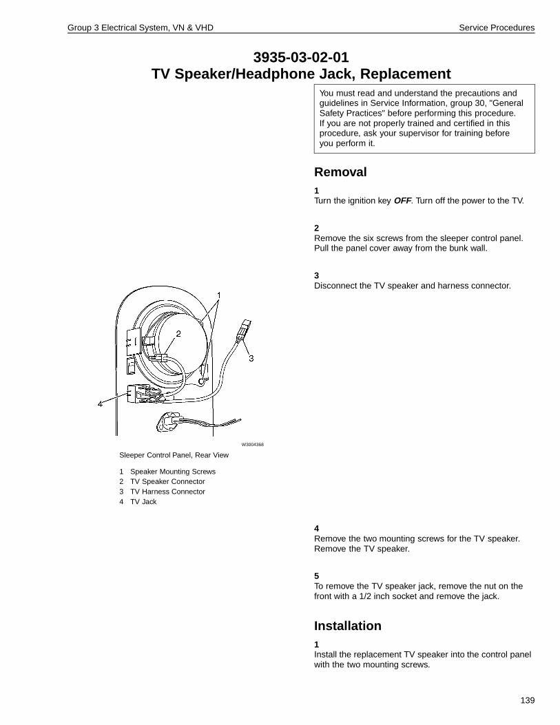
Group 3 Electrical System, VN & VHD Service Procedures
3935-03-02-01TV Speaker/Headphone Jack, Replacement
You must read and understand the precautions andguidelines in Service Information, group 30, "GeneralSafety Practices" before performing this procedure.If you are not properly trained and certified in thisprocedure, ask your supervisor for training beforeyou perform it.
Removal1Turn the ignition key OFF. Turn off the power to the TV.
2Remove the six screws from the sleeper control panel.Pull the panel cover away from the bunk wall.
3
W3004368
Sleeper Control Panel, Rear View
1 Speaker Mounting Screws2 TV Speaker Connector3 TV Harness Connector4 TV Jack
Disconnect the TV speaker and harness connector.
4Remove the two mounting screws for the TV speaker.Remove the TV speaker.
5To remove the TV speaker jack, remove the nut on thefront with a 1/2 inch socket and remove the jack.
Installation1Install the replacement TV speaker into the control panelwith the two mounting screws.
139
Group 3 Electrical System, VN & VHD Service Procedures
2Install the replacement speaker jack and secure the nutwith a 1/2 inch socket.
3Connect the connectors.
4Turn on power to the TV. Check the speaker for operation.
5Insert the sleeper control panel into the trim panel. Installthe six mounting screws.
140
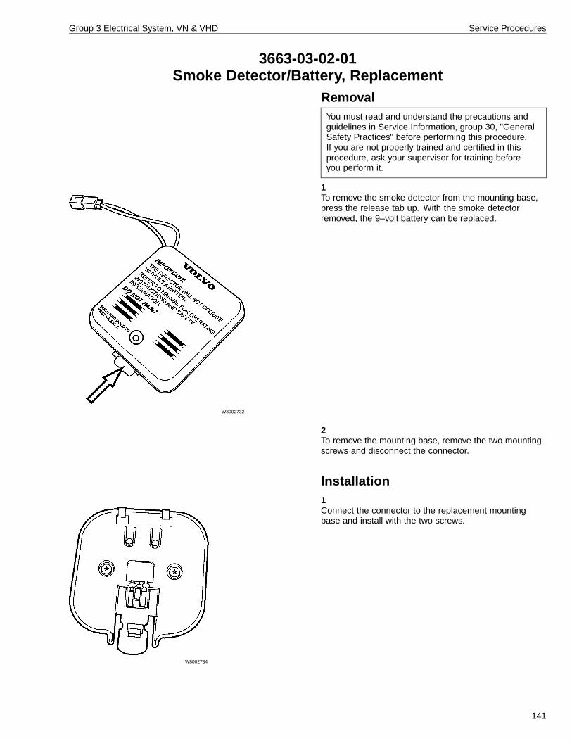
Group 3 Electrical System, VN & VHD Service Procedures
3663-03-02-01Smoke Detector/Battery, Replacement
RemovalYou must read and understand the precautions andguidelines in Service Information, group 30, "GeneralSafety Practices" before performing this procedure.If you are not properly trained and certified in thisprocedure, ask your supervisor for training beforeyou perform it.
1
W8002732
To remove the smoke detector from the mounting base,press the release tab up. With the smoke detectorremoved, the 9–volt battery can be replaced.
2To remove the mounting base, remove the two mountingscrews and disconnect the connector.
Installation1
W8002734
Connect the connector to the replacement mountingbase and install with the two screws.
141

Group 3 Electrical System, VN & VHD Service Procedures
2Check that a known good 9–volt battery is installed inthe smoke detector. Snap the smoke detector intothe mounting base. Be sure the release tab is lockedinto position.
3Test the smoke detector for proper operation by pressingthe function button/indicator light for 5 seconds. Ifthe battery is OK the alarm should sound as long asthe button is pressed.
142
Operation Numbers
3714-03-02-02 Fusible Link, Replacement (Battery Side) ................................................................................................ 84
3714-03-02-01 Fusible Link, Replacement (Ground Cable) ............................................................................................. 88
3645-03-02-05 Central Door Lock Module, Replacement ................................................................................................ 91
3645-03-02-05 Central Door Lock Module, Replacement ................................................................................................ 93
3341-03-02-01 Ignition Switch, Replacement ................................................................................................................... 95
3341-03-02-02 Ignition Switch and Housing, Replacement ............................................................................................. 98
3623-03-02-02 Air Horn Contact, Replacement ............................................................................................................ 102
3623-03-02-04 City Horn Contact, Replacement ........................................................................................................... 107
3621-03-02-03 City Horn, Replacement ......................................................................................................................... 109
3621-03-02-02 Air Horn Solenoid, Replacement ............................................................................................................ 110
3643-03-02-01 Turn Signal/CC Switch Assembly, Replacement .................................................................................... 111
3646-03-02-11 Hazard Warning Switch, Replacement .................................................................................................. 114
3646-03-02-33 Back of Cab Lamp Switch, Replacement ............................................................................................... 114
3646-03-02-34 Fan Switch, Replacement ...................................................................................................................... 114
3646-03-02-35 PTO Switch, Replacement ..................................................................................................................... 114
3646-03-02-36 Bunk Overhead Lamp Switch, Replacement ......................................................................................... 114
3646-03-02-37 Headlamp Interrupt Switch, Replacement ............................................................................................. 114
3646-03-02-38 Snowplow Lamp Switch, Replacement .................................................................................................. 114
3646-03-02-39 Smoke Detector Disable Switch, Replacement ...................................................................................... 114
3646-03-02-29 Sleeper Control Panel Switch, Replacement ......................................................................................... 118
3646-03-02-22 Auxiliary Switch, Replacement ............................................................................................................... 118
3646-03-02-24 Marker Interrupt Switch, Replacement ................................................................................................... 118
3646-03-02-40 Engine/Exhaust Brake Switch, Replacement ......................................................................................... 118
3646-03-02-41 Traction Control Switch, Replacement ................................................................................................... 118
3646-03-02-26 Heated Mirror Switch, Replacement ...................................................................................................... 118
3646-03-02-42 Lift Axle Switch, Replacement ............................................................................................................... 118
3646-03-02-43 Beacon Lamp Switch, Replacement ...................................................................................................... 118
3646-03-02-32 Pneumatic Switch, Replacement ........................................................................................................... 121
3646-03-02-06 Headlamp/Parking Lamp Switch, Replacement ..................................................................................... 123
3646-03-02-23 Fog/Driving Lamp Switch, Replacement ................................................................................................ 126
3646-03-02-12 Dash Dimmer Control Switch, Replacement .......................................................................................... 129
3647-03-02-01 Cigar Lighter, Replacement ................................................................................................................... 132
3646-03-02-28 Window/Power Mirror Switch, Replacement .......................................................................................... 134
3838-03-02-02 Digital Clock, Replacement (Sleeper) .................................................................................................... 137
3935-03-02-01 TV Speaker/Headphone Jack, Replacement ......................................................................................... 139
3663-03-02-01 Smoke Detector/Battery, Replacement .................................................................................................. 141


Volvo Trucks North America, Inc.P.O. Box 26115, Greensboro, NC 27402-6115
Volvo Trucks Canada, Ltd.5600A Cancross Court, Mississauga, Ontario L5R 3E9
http://www.volvotrucks.volvo.com
PV776-20 007111 (1000) 04.2004 © Volvo Trucks North America, Inc., 2004